format dgt - sime belgium gb... · –“format dgt 25-30 bf ... * gas consumption figures express...
TRANSCRIPT

ISO 9001: 2000CERTIFIED COMPANY
F O R M AT D G T
Fonder ie S IME S .p .A Cod . 6304368B - 10/10
ES
PT
ENG
INSTALLER INSTRUCTIONS
CONTENTS
1 DESCRIPTION OF THE BOILER . . . . . . . . . . . . . . . . . . . . . . . . . . . . . . . . . . . . . . . . . . . . . . . . . . . . . . . . . . . . . . . pag. 64
2 INSTALLATION . . . . . . . . . . . . . . . . . . . . . . . . . . . . . . . . . . . . . . . . . . . . . . . . . . . . . . . . . . . . . . . . . . . . . . . . . . . . . . pag. 69
3 CHARACTERISTICS . . . . . . . . . . . . . . . . . . . . . . . . . . . . . . . . . . . . . . . . . . . . . . . . . . . . . . . . . . . . . . . . . . . . . . . . . pag. 80
4 USE AND MAINTENANCE . . . . . . . . . . . . . . . . . . . . . . . . . . . . . . . . . . . . . . . . . . . . . . . . . . . . . . . . . . . . . . . . . . . pag. 84
IMPORTANTWhen carrying out commissioning of the boiler, you are highly recommended to perform the following checks:
– Make sure that there are no liquids or inflammable materials in the immediate vicinity of the boiler.
– Make sure that the electrical connections have been made correctly and that the earth wire is connected to a
good earthing system.
– Open the gas tap and check the soundness of the connections, including that of the burner.
– Make sure that the boiler is set for operation for the type of gas supplied.
– Check that the flue pipe for the outlet of the products of the combustion is unobstructed and has been properly
installed.
– Make sure that any shutoff valves are open.
– Make sure that the system is charged with water and is thoroughly vented.
– Check that the circulating pump is not locked.
– Purge the system, bleeding off the air present in the gas pipe by operating the pressure relief valve on the gas
valve inlet.
– The installer must provide the user with instruction in operation of the boiler and safety devices and hand over the
instruction booklet to the user.
FONDERIE SIME S.p.A. of Via Garbo 27 - Legnago (VR) - Italy declares that its hot water boilers, which bear theCE mark under Gas Directive 90/396/CEE and are fitted with a safety thermostat calibrated to a maximum of110°C, are not subject to application of PED Directive 97/23/CEE as they meet the requirements of article 1paragraph 3.6 of the Directive.
FOR
MAT
DG
T - E
NG
LIS
H

1.2 DIMENSIONI
1.2.1 “25 OF” model (fig. 1)
D
Fig. 1
Fig. 1/a
1.2.2 “25 - 30 BF” models (fig. 1/a)
64
1.1 INTRODUCTION
“FORMAT DGT” are the gas fuelled burnergroups for heating and the production ofhot sanitary water, constructed to satisfythe needs of collective residential housingand modern plant. They are apparatuses which conform to
the European directives 2009/142/CE,2004/108/CE, 2006/95/CE and92/42/CE. The can be fuelled by natural gas (G20) orLPG (G30-G31). This booklet gives the instructions for thefollowing models:– “FORMAT DGT 25 OF” open combustion
chamber with natural draw.
– “FORMAT DGT 25-30 BF” sealed com-bustion chamber forced flow.
The instructions given in this manual areprovided to ensure proper installation andperfect operation of the appliance.
1 DESCRIPTION OF THE BOILER
CONNECTIONSR C.H. return
G 3/4” (UNI-ISO 228/1)M C.H. flow
G 3/4” (UNI-ISO 228/1)G Gas connection
G 3/4” (UNI-ISO 228/1)E D.H.W. inlet
G 1/2” (UNI-ISO 228/1)U D.H.W. outlet
G 1/2” (UNI-ISO 228/1)
DIMENSIONS 25 OFD mm 130
CONNECTIONSR C.H. return
G 3/4” (UNI-ISO 228/1)M C.H. flow
G 3/4” (UNI-ISO 228/1)G Gas connection
G 3/4” (UNI-ISO 228/1)E D.H.W. inlet
G 1/2” (UNI-ISO 228/1)U D.H.W. outlet
G 1/2” (UNI-ISO 228/1)
DIMENSIONS 25 BF 30 BFL mm 400 450K mm 203 221

1.3 TECHNICAL FEATURES
65
ES
PT
ENG
* Gas consumption figures express the lowest calorific power of pure gas under standard conditions at 15°C – 1013 mbar; this figure may differ from the actualfigure, which is dependent on gas composition and environmental conditions.
FORMAT DGT 25 OF 25 BF 30 BF
Heat output
Nominal kW 22.8 23.6 27.8
Reduced kW 8.5 7.5 9.0
Heat input
Nominal kW 25.0 25.5 30.0
Reduced kW 10.0 9.2 10.8
Thermal yield 100% useful 91.3 93.0 93.0
Thermal yield useful at 30% of load 90.1 90.5 91.1
Termal efficiency (CEE 92/42 directive) !! !!! !!!
Losses after shutdown to 50°C (EN 483) W 182 82 92
Supply voltage V-Hz 230-50 230-50 230-50
Adsorbed power consumption W 85 110 115
Electrical protection grade IP X4D X5D X5D
C.H. setting range °C 40÷80 40÷80 40÷80
Water content boiler l 3.40 3.25 3.50
Maximum water head bar 3 3 3
Maximum temperature °C 85 85 85
Header tank capacity l 8 8 8
Header tank pressure bar 1.2 1.2 1.2
D.H.W. setting range °C 10÷60 10÷60 10÷60
D.H.W. flow rate (EN 625) l/min 10.9 11.3 13.0
Continuous D.H.W. flow rate Δt 30°C l/min 10.9 11.3 13.4
Minimum D.H.W. flow rate l/min 2.0 2.0 2.0
D.H.W pressure min/max bar 0.2/7 0.2/7 0.2/7
D.H.W. pressure min. nom. power bar 0.3 0.4 0.3
Smokes temperature min/max °C 83/110 94/116 100/125
Smokes flow min/max g/s 16/18 17/16 19/19
CE certification No. 1312BU5373 1312BU5372 1312BU5372
Category II2H3+ II2H3+ II2H3+
Type of appliance B11BS B22P-52P/C12-32-42-52-62-82 B22P-52P/C12-32-42-52-62-82
NOx emission class 3 (< 150 mg/kWh) 3 (< 150 mg/kWh) 3 (< 150 mg/kWh)
Weight when empty kg 26 30 31
Main burner nozzle
Quantity nozzles n° 13 11 13
Nozzle diameter G20 mm 1.30 1.30 1.30
Nozzle diameter G30/G31 mm 0.72 0.80 0.78
Gas consumption *
Natural gas (G20) m3/h 2.61 2.70 3.17
LPG (G30/G31) kg/h 1.96 2.01 2.37
Burner gas pressure min/max
Natural gas (G20) mbar 1.6/9.5 1.9/13.5 1.9/13.2
Butane (G30) mbar 4.6/27.7 3.7/27.9 4.1/26.8
Propane (G31) mbar 4.6/35.7 3.7/35.9 4.1/34.8
Gas supply pressure
Natural gas (G20) mbar 20 20 20
Butane (G30) mbar 28–30 28–30 28–30
Propane (G31) mbar 37 37 37

66
1.4 FUNCTIONAL DIAGRAM (fig. 2)
Fig. 2
KEY1 Fan (vers. BF)2 Primary exchanger4 C.H. sensor (SM1/SM2)5 Combustion chamber6 Gas valve7 Water pressure valve8 Circulator with air release vent
10 Hydrometer11 Expansion vessel12 D.H.W. flow meter13 By-pass 14 D.H.W. filter15 Boiler discharge16 3 BAR safety valve18 Connection plate (optional)
19 D.H.W. cock (optional)20 Gas cock (optional)21 C.H. flow cock (optional)22 C.H. return cock (optional)23 Loading system24 D.H.W. exchanger with plates 25 C.H. filter26 Deviator valve
CONNECTIONSU D.H.W. outletE D.H.W. inletG Gas connectionM C.H. flowR C.H. return

67
ES
PT
ENG
6
7 8
5
9
4
3
2
1
11
10
1.5 MAIN COMPONENTS (fig. 3 - fig. 3/a)
Fig. 3
“25 OF” model
KEY1 Control panel2 Circulation pump3 Air relief valve4 Burners5 Expansion vessel
6 C.H. sensor (SM1/SM2)7 Smoke stat8 Smoke chamber9 Primary exchanger
10 Ignition/detection electrode11 Gas valve

68
1
2
3
4
5
78
6
9
10
11
Fig. 3/a
“25 - 30 BF” models
KEY1 Control panel2 Circulation pump3 Air relief valve4 Burners5 Expansion vessel
6 C.H. sensor (SM1/SM2)7 Air pressure switch8 Fan9 Primary exchanger
10 Ignition/detection electrode11 Gas valve

69
ES
PT
ENG
The boiler must be installed in a fixed loca-tion and only by specialized and qualifiedfirms in compliance with all instructions con-tained in this manual. Furthermore, theinstallation must be in accordance with cur-rent standards and regulations.
2.1 INSTALLATION
- In the rooms where “type B” boilers areinstalled, the air required for correctcombustion of the gas consumed by theappliance must be able to flow in. It istherefore necessary to make openingsthat cannot be blocked in the outer walls,which must be at least 6 cm2 for everykW of thermal capacity installed andwith, in any case, a minimum of 100cm2.
- “Type C” appliances, with combustionchamber and air supply sealed off fromthe environment, can be installed in anyroom in the house.
- “Type B and C” boilers are suitable forfunctioning in a partially protected place,as according to EN 297, with maximumenvironmental temperature of 60°C andminimum of -5°C. We recommend instal-lation of these boilers under the protru-ding slope of a roof, on a balcony, or in aprotected niche, always providing theyare not directly exposed to adverseweather (rain, hail, snow). The boilers areprovided already equipped with anti-free-ze functions.
2.1.1 Anti-freeze function
The boilers are equipped with anti-freezefunction which activates the pumps and theburner when the temperature of the watercontained inside the appliance drops tobelow value PAR 10. The anti-freeze functionis ensured, however, only if:- the boiler is correctly connected to the
gas and electricity supply circuits;- the boiler is constantly fed;- the boiler ignition is not blocked;- the essential components of the
boiler are all in working orderIn these conditions the boiler is protectedagainst frost down to an environmental tem-perature of -5°C.
ATTENTION: In the case of installation in aplace where the temperature drops below0°C, the connection pipes must be protec-ted.
2.2 COMPLEMENTARY ACCESSORIES
To facilitate connecting the boiler to thesystem, the following accessories can besupplied on request, complete with instruc-tions for assembly:- Installation plate code 8075427- Elbows and gas taps/sanitary water out-
put set code 8075418- Taps kit code 8091806- Polyphosphates doser kit code 81071700- Kit of couplings for replacing wall-hung
boilers of other makes code 8093900- Solar kit for the instantaneous code
8105101- Protection connection kit “25 BF” code
8094520- Protection connection kit “30 BF” code
8094521
2.3 CONNECTING UP SYSTEM
To protect the heat system from damagingcorrosion, incrustation or deposits, beforeinstallation it is extremely important to cleanthe system using suitable products such as,for example, Sentinel X300 (new systems),X400 and X800 (old systems) or FernoxCleaner F3. Complete instructions are provided with theproducts but, for further information, youmay directly contact SENTINEL PERFOR-MANCE SOLUTIONS LTD or FERNOX COOK-SON ELECTRONICS. For long-term protec-tion agains corrosion and deposits, the useof inhibitors such as Sentinel X100 or Fer-nox Protector F1 is recommended aftercleaning the system. It is important to checkthe concentration of the inhibitor after eachsystem modification and during maintenan-ce following the manufacturer’s instructions(specific tests are available at your dealer). The safety valve drain must be connected toa collection funnel to collect any dischargeduring interventions. If the heating system ison a higher floor than the boiler, install theon/off taps supplied in kit optional on theheating system delivery/return pipes. WARNING: Failure to clean the heat
system or add an adequate inhibitor invali-dates the device’s warranty.Gas connections must be made in accor-dance with current standards and regula-tions. When dimensioning gas pipes from themeter to the module, both capacity volume(consumption) in m3/h and gas densitymust be taken into account. The sections of the piping making up thesystem must be such as to guarantee a sup-ply of gas sufficient to cover the maximumdemand, limiting pressure loss between thegas meter and any apparatus being used tonot greater than:
– 1.0 mbar for family II gases (natural gas);– 2.0 mbar for family III gases (butane or
propane).
An adhesive data plate is sticked inside thefront panel; it contains all the technical dataidentifying the boiler and the type of gas forwhich the boiler is arranged.
2.3.1 Filter on the gas pipe
The gas valve is supplied ex factory with aninlet filter, which, however, is not adequate toentrap all the impurities in the gas or in gasmain pipes. To prevent malfunctioning of thevalve, or in certain cases even to cut out thesafety device with which the valve is equip-ped, install an adequate filter on the gas pipe.
2.5 SYSTEM FILLING (fig. 4)
Filling of the boiler and the system is done bythe system filling (3 fig. 4). The charge pressure, with the system cold,
2 INSTALLATION
Fig. 4
KEY1 D.H.W. flow meter (white)2 Sensor effect HALL (blue)3 System filling (blue)4 3 BAR safety valve5 Boiler discharge6 Automatic by-pass (blue)
7 Water pressure valve8 Deviator valve9 C.H. filter (blue)
NOTE: They are evidenced in blue/whitethe members for which are previewedthe verification and the control.
32
1
4 5 6
7 8
9

70
must be between 1 and 1.2 bar. Filling must be done slowly so as to allowany air bubbles to be bled off through the airvalves. Should the pressure have risen well abovethe limit expected, discharge the over pres-sure by opening the pressure-relief valve.
2.5.1 Emptying the system (fig. 4)
Use the drain tap to empty the system (5fig. 4). Turn off the boiler before doing this.
2.6 FLUES/CHIMNEYS
A chimney or flue for the evacuation of thecombustion products into the atmospheremust correspond to the requisites prescri-bed by the laws in force.In particular, the specific prescriptions oflaw relative to boilers with natural draughtin collective pipes (type B) and those for boi-lers with forced draught (type C) must berespected.
2.6.1 Ducting of existing chimneys
To recover or duct existing chimneys, ductsdeclared suitable for the purpose by themanufacturer must be used, and the instal-lation and use modalities indicated by thesaid manufacturer must also be followedas well as the prescriptions of StandardUNI 10845.
2.7 INSTALLATION OF COAXIAL DUCT (versions "BF")
2.7.1 Accessories 60/100 (fig. 5)
The 60/100 coaxial duct is supplied onrequest in kit code 8084811.The diagrams of f ig. 5 illustrate someexamples of different types of dischargemodalit ies al lowed and the maximumlengths that can be reached.
2.7.2 Diaphragm for 60/100 coaxial duct (fig. 5/a)
The boiler is supplied with a diaphragm of
ø 79 (version 25 BF), ø 81 (version 30BF). Use the diaphragms according to the indi-cations of fig. 5/a.
C12
C32
C42
3
1
2
7
64
3
2
8
x
y
max 5,0 m per vers. “20”max 3,5 m per vers. "25"max 3,0 m per vers. "30-35"
x + y = max 5,0 m per vers. "20"x + y = max 3,5 m per vers. "25"x + y = max 3,0 m per vers. "30-35"
min
1,3
m -
max
5 m
KEY1 Coaxial flue kit L. 810 code 80848112 a Extension L. 1000 code 80961032 b Extension L. 500 code 80961023 Vertical extension L. 200 code 80869084 Additional 90° curve code 80958016 Articulated tile code 80913007 Roof outlet terminal L. 1284 code 80912008 Vertical condensation collector L. 200 code 8092803
Fig. 5
IMPORTANT: – Each additional 90° curve
installed reduces the availablelength by 1.0 metres.
– Each additional 45° curveinstalled reduces the availablelength by 0.50 metres.
- The insertion of the condensa-tion collector (8) is obligatoryfor vertical stretches of morethan 1.3 metres.
Fig. 5/a
For discharge types C12-C42, use the diaphragms supplied with the boiler:- ø 79.0 for version “25” only when the length of the coaxial duct is less than 1 metre.- ø 81.0 for version “30” only when the length of the coaxial duct is less than 1 metre.
For discharge types C32, use the following diaphragms according to the length of the duct and withoutadditional curves:
Installations with vertical Installations with vertical condensationextension L. 200 code 8086908 * collector code 8092803 *
Models “25 BF - 30 BF” Models “25 BF - 30 BF”Diaphragm Diaphragm Without Diaphragm Diaphragm Without
ø 79 ø 81 diaphragm ø 79 ø 81 diaphragm
L max = 2.5 m L max = 2.5 m L max = 5 m L max = 2.5 m L max = 2.5 m L max = 5 m
* Minimum length of duct L = 1.3 m.

71
ES
PT
ENG
2.7.3 Accessories ø 80/125 (fig. 6)
The ø 80 coaxial duct is supplied on reque-st in a kit code 8084830 complete withassembly instructions.With the curve supplied in the kit, the maxi-mum horizontal length of the duct must beno more than 6 metres.The diagrams in fig. 6 show some examplesof the different types of ø 80/125 coaxialdischarge modalities.
2.8 INSTALLATION OF SEPARATE DUCTS (vers. “25-30 BF”)
When installing, the provisions of the lawsin force must be adhered to, as well as cer-tain practical suggestions:
– With aspiration directly from outside,when the duct is longer than 1 metre, itis advisable to insulate the said duct inorder to avoid the formation of dew onthe outside of the pipe when the weather
is particularly cold.
– With ducts with discharge positionedoutside the building, or in cold environ-ments, insulation is necessary to avoiddifficulty in starting the burner. In thesecases, a condensation system on thepipes must be provided for.
– If the pipe passes through inflammablewalls, insulate the stretch of the fumesdischarge pipe that passes through the
C12
C32
C42
27
64
1
2min
. 4 m
- m
ax 7
m
8
x
y
x + y = min. 3,5 m/max 6 m "25"x + y = min. 3,0 m/max 6 m "30-35"
5
53 8
2
1
1
min. 3,5 m - max 6 m "25"min. 3,0 m - max 6 m "30-35"
2
Fig. 6
KEY1 Coaxial duct kit code 80848302 Extension L. 1000 code 80961303 Vertical extension L. 200 with coupling code 80869084a Additional 90° curve code 80958204b Additional 45° curve code 80959205 Adapter for 80/125 code 80931206 Tile for joint code 80913007 Terminal for roof exit L. 1284 code 80912008 Vertical condensation collector L. 200 code 8092803
IMPORTANT: – Each additional 90° curve installed reduces the available length by 1.0 metres.– Each additional 45° curve installed reduces the available length by 0.80 metres.– The insertion of the condensation collector (8) is obligatory in C32 discharge type.– The insertion of the condensation collector (8) is obligatory in C42 discharge type
when the stretch "y” is longer than 1.3 metres.

72
wall with rounded glass wool 30 mmthick and with a density of 50 kg/m2.
The maximum total length, which is thesum of lengths of the aspiration anddischarge pipes, is determined by theloss of charge of the single accessoriesinserted and must not result as morethan 9.0 mm H2O in version “25 BF” and9.5 mm H2O in version “30 BF”.For the loss of charge of the accessories,refer to Table 1 and to the example given infig. 7.
2.8.1 Air/combustion products divider(fig. 8 - fig. 8/a)
The air/combustion products divider cod.8093020 (fig. 8) is supplied with the aspi-ration diaphragm that must be engaged,depending on the maximum head lossaccepted in both ducts, as indicated in fig.8/a.
2.8.2 Outlet systems (fig. 9)
The diagrams in fig. 9 illustrate a numberof examples of different types of separateoutlets.
Fig. 7
Calculation example of the head loss of a “25 BF” vers. boiler (installation allowed as the sumof the head losses of the accessories used is less than 9.0 mmH2O):
Intake Outlet7 meter horizontal pipe ø 80 x 0.20 1.40 –7 meter horizontal pipe ø 80 x 0.30 – 2.10No. 2 90° elbows ø 80 x 0.35 0.70 –No. 2 90° elbows ø 80 x 0.40 – 0.80No. 1 wall terminal ø 80 0.15 0.50
Total head loss 2.25 + 3.40 = 5.65 mmH2O
With this total head loss, remove the segments from No. 1 to No. 6 from diaphragm in the intake pipe.
TABLE 1
Accessories ø 80 Load loss (mmH2O)
25 BF 30 BF
Intake Outlet Intake Outlet
90° elbow MF 0.35 0.40 0.45 0.5045° elbow MF 0.30 0.35 0.40 0.45Extension L. 1000 (horizontal) 0.20 0.30 0.25 0.35Extension L. 1000 (vertical) 0.20 0.10 0.25 0.15Wall terminal 0.15 0.50 0.20 0.80T-shaped condensation collector --- 0.80 --- 1.00Roof exit terminal* 1.60 0.10 2.00 0.20* The loss of the roof exit terminal in aspiration concludes the collector code 8091400
1
2
3
4
LK
120
190
190
ø 8
0
ø 8
0
125
125
Fig. 8
KEY1 Divider with vent2 Inlet air diaphragm3 Air intake bend4 Elbow product discharge
25 BF 30 BFK mm 203 221L mm 400 450

73
ES
PT
ENG
2.9 FORCED EXHAUST TYPE B22P-B52P (fig. 10)
Comply with the following requirementsduring installation:
– Insulate the exhaust pipe and install acondensation collection system at thebase of the vertical pipe.
– If the pipe passes through combustiblewalls, insulate the section of the flue pipe
passing through the wall with a 30 mmthick fibreglass pipe covering with a den-sity of 50 kg/m3.
In “25-30 BF” models this type of exhaust
max 0,5 m
max
0,5
m
C12B52
1
4
9
C52B52
C32
C42
3
2
11
10
C82B22
6
5
6
12
3
11
10
3
7
1
8
3
1
3
2
3
3 2
1
3
23 63
1
8 3
KEY1 Air/combustion product divider code 8093020
2a 90° elbow MF (n° 6) code 80774102b 90° elbow MF with intake code 80774072c Isolated 90° elbows MF code 80774083a Extension L. 1000 (n° 6) code 80773093b Insulated extension L. 1000 code 80773063c Extension L. 500 (n° 6) code 80773083d Extension L. 135 with intake code 8077304
4 Outlet terminal code 80895015 Int.-est. ring kit code 80915006 Intake terminal code 80895007 45° elbow MF (n° 6) code 80774118 Condensation outlet L. 135 code 80928009 Doubler fitting code 8091400
10 Tile with articulated joint code 809130011 Roof outlet terminal L. 1390 code 809120112 Tee condensation outlet code 8093300
Fig. 9IMPORTANT: In type C52 the outlet and inlet flues must not come out on opposite walls.
CONFIGURATION C62: discharge and aspiration is by means of pipes available on sale and certified separately (the pressure loss in theducts must be calculated according to the Standard UNI EN 13384)
Fig. 8/a
No. segments Total load loss mm H2Oto remove 30 BF 25 BF
none 0 ÷ 0.8 0 ÷ 2.0No. 1 0.8 ÷ 1.5 2.0 ÷ 3.0
No. 1 e 2 1.5 ÷ 2.4 3.0 ÷ 4.0from No. 1 to 3 2.4 ÷ 3.2 -from No. 1 to 4 3.2 ÷ 4.0 4.0 ÷ 5.0from No. 1 to 5 4.0 ÷ 4.8 -from No. 1 to 6 4.8 ÷ 5.6 5.0 ÷ 6.0from No. 1 to 7 5.6 ÷ 6.5 6.0 ÷ 7.0from No. 1 to 8 6.5 ÷ 7.3 -from No. 1 to 9 7.3 ÷ 7.8 7.0 ÷ 8.0
from No. 1 to 10 7.8 ÷ 8.4 -without diaphragm 8.4 ÷ 9.5 8.0 ÷ 9.0

74
pipe is installed using the special kit, code8093020. For kit assembly instructions,refer to point 2.8.1. Protect the intake with the optional acces-sory, code 8089501 (fig. 10). The air/com-bustion product divider code 8093020 issupplied with aspiration diaphragm thatmust be engaged, depending on the maxi-mum head loss allowed, as indicated in fig.8/a.Maximum flow resistance must be nomore than 9.0 mm H2O in vers. “25 BF” -9.5 mm H2O in vers. “30 BF”.As the maximum pipe length is determinedby adding up the flow resistance of thevarious individual accessories installed,refer to Table 1 for calculation.
2.10 POSITIONING OF OUTLETTERMINALS (fig. 11)
The outlet terminals for forced draughtsystems may be located on the outer wallsof the building Table 2 shows approximate,non-binding minimum distances to be metfor a building of the type shown in fig. 11.
1) Terminals below a practicable balcony must be located in such away that the total path of the smoke from its outlet point fromthe terminal to its outlet point from the external perimeter of thebalcony, including the height of possible railings, is not less than2000 mm.
2) When siting terminals, where materials that may be subjectto the action of the combustion products are present in thevicinity, e.g., eaves, gutters and downspouts painted or madeof plastic material, projecting timberwork, etc., distances ofnot less than 1500 mm must be adopted, unless adequateshielding is provided to guard these materials.
Fig. 11
Cod. 8089501
Fig. 10
TABLE 2
Siting of terminal Appliances from 7 to 35 kW(distances in mm)
A - below openable window 600B - below ventilation opening 600C - below eaves 300D - below balcony (1) 300E - from adjacent window 400F - from adjacent ventilation opening 600G - from horizontal or vertical soil or drain pipes (2) 300H - from corner of building 300I - from recess in building 300L - from ground level or other treadable surface 2500M - between two terminals set vertically 1500N - between two terminals set horizontally 1000O - from a surface facing without
openings or terminals 2000P - as above but with openings and terminals 3000

75
ES
PT
ENG
2.11 ELECTRICAL WIRING
If you must replace the electric powercable supplied with the boiler, order it exclu-sively from Sime.The power supply must be single-phase230V - 50 Hz through a main switch pro-tected by a fuse with a distance of at least3 mm between contacts.
NOTE: The boiler must be connected withan efficient grounding system. SIME shallnot be held liable for injury or damageresulting from failure to ground the boi-ler.
ATTENTION: Before every intervention onthe boiler, cut off the electricity supply bymeans of the main switch of the system,since even if the boiler is "OFF", the elec-trical panel remains connected to theelectricity.
2.11.1 Chronothermostat connection
Remove the boiler casing, tilt the controlpanel and connect the chronothermostatto the 6 pole terminal board as indicated inthe boiler electrical diagram (see para-graph 2.12) after having removed the exi-sting bridge. The chronothermostat to be used must beof a class conforming to the standard EN60730.1 (clean electrical contact).
2.11.2 Remote control CR 63connection (optionals)
The boiler is designed for connection to aremote control unit CR 63 code 8092219coupled to an optional expansion kit code8092240.The remote control unit allows for complete
remote control of the boiler, except releaseof the boiler. Whenn the connection has been made theboiler display will show the following messa-ge: Cr.For installation and use of the remote con-trol, follow the instructions in the package.
2.11.3 External sensor connection(optional)
The boiler is designed for connection to anexternal temperature sensor, supplied onrequest (code 8094101), which can auto-matically regulate the temperature value ofthe boiler output according to the externaltemperature. For installation, follow the instruction in thepackage. It is possible to make correctionsto the values read by the drill acting on thePAR 4.
2.11.4 Use with different electronic systems
Some examples are given below of boilersystems combined with different electronicsystems. The electrical connections to theboiler refer to the wording on the diagrams(figs. 13-13/a). The zone valve controlstarts at every demand for heating of theremote control.
Description of the letters indicating thecomponents shown on the system dia-grams from 1 to 6:
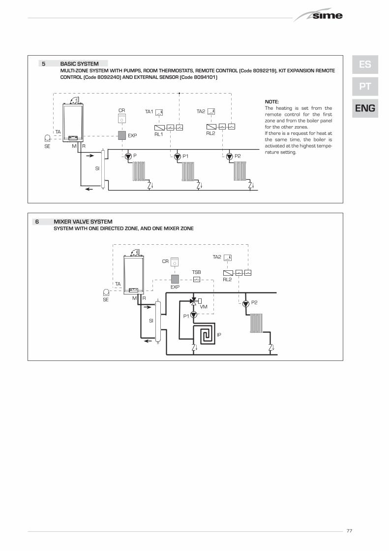
M System outputR System returnCR Remote control CR 63SE External temperature sensorTA 1-2 Zone room thermostatVZ 1-2 Zone valveRL 1-2 Zone relaySl Hydraulic separatorP 1-2 Zone pumpIP Floor systemEXP Expansion card
(code 6301430)VM Thermostatic mixer valveTSB Safety thermostat low
temperature
RM
SE
TA
CR
EXP
1 BASIC SYSTEMSYSTEM WITH A DIRECT ZONE AND ROOM THERMOSTAT, OR WITHA REMOTE CONTROL (Code 8092219), KIT EXPANSION REMOTECONTROL (Code 8092240) AND EXTERNAL SENSOR (Code8094101)

76
TA
RMSE
TA1 TA2TA
P2
RL
SI
RL1 RL2
P1P
TA
RM
VZ VZ1
TA2
VZ2
TA1
CR
EXP
SE
2 BASIC SYSTEMMULTI-ZONE SYSTEM WITH VALVE, ROOM THERMOSTAT AND EXTERNAL SENSOR (Code 8094101)
3 BASIC SYSTEMMULTI-ZONE SYSTEM WITH PUMP, ROOM THERMOSTATS AND EXTERNAL SENSOR (Code 8094101)
4 BASIC SYSTEMMULTI-ZONE SYSTEM WITH VALVE, ROOM THERMOSTATS, REMOTE CONTROL (Code 8092219), KIT EXPANSION REMO-TE CONTROL (Code 8092240) AND EXTERNAL SENSOR (Code 8094101)
TA
RM
SE
TA
VZ
TA1
VZ1
TA2
VZ2
PARAMETERS SETTINGS
Set the opening time of the VZ zonevalve:PAR 17 = SYSTEM PUMP
ACTIVATION DELAY
77
ES
PT
ENG
TA
SI
RM
TA1 TA2
P2
RL1 RL2
P1P
SE
CR
EXP
TA
RMSE
TA2
SI
RL2
P2
P1
VM
IP
CR
EXP
TSB
6 MIXER VALVE SYSTEMSYSTEM WITH ONE DIRECTED ZONE, AND ONE MIXER ZONE
5 BASIC SYSTEMMULTI-ZONE SYSTEM WITH PUMPS, ROOM THERMOSTATS, REMOTE CONTROL (Code 8092219), KIT EXPANSION REMOTECONTROL (Code 8092240) AND EXTERNAL SENSOR (Code 8094101)
NOTE:The heating is set from theremote control for the firstzone and from the boiler panelfor the other zones.If there is a request for heat atthe same time, the boiler isactivated at the highest tempe-rature setting.

78
2.12 BOILER ELECTRICAL DIAGRAM (fig. 13 - fig. 13/a)
PA (24 VDC)
SM1/SM2 (3,3 VDC)
S.AUX(3,3 VDC)
SE (3,3 VDC)TA(24 VDC)
TF(24 VDC)
M (17 VDC)
FLM(12 VDC)
EXP(24 VDC)Cod. 6301440
Fig. 13
Modello “25 OF”
KEYF Fuse (1.6 AT)TRA Ignition transformerPI System pumpEAR Ignition/detection electrodeEV1-2 Gas valve coilTF Smoke thermostatM ModulatorSM1/SM2 Heating sensorFLM D.H.W. flow meterVD Deviator valvePA Water pressure valveTA Environment thermostat
SE External sensor (optional)S.AUX Auxiliary sensorEXP Expansion card remote control (optional)
NOTE: Connect TA to the clamps 5-6 after havingremoved the bridge.
CONNECTOR SPARE PART CODES:CN4 code 6316298CN5 code 6316253CN6 code 6316255CN7 code 6316278

79
ES
PT
ENG
SM1/SM2(3,3 VDC)
PF (24 VDC)
S.AUX(3,3 VDC)
SE (3,3 VDC)TA(24 VDC)
M (17 VDC)
FLM (12 VDC)
EXP (24 VDC)
PA (24 VDC)
Cod. 6301440
Fig. 13/a
“25-30 BF” models
KEYF Fuse (1.6 AT)TRA Ignition transformerPI System pumpV FanEAR Ignition/detection electrodeEV1-2 Gas valve coilPF Smoke thermostatM ModulatorSM1/SM2 Heating sensorFLM D.H.W. flow meterVD Deviator valvePA Water pressure valveTA Environment thermostat
SE External sensor (optional)S.AUX Auxiliary sensorEXP Expansion card remote control (optional)
NOTE: Connect TA to the clamps 5-6 after havingremoved the bridge.
CONNECTOR SPARE PART CODES:CN4 code 6316277CN5 code 6316253CN6 code 6316252CN7 code 6316278

80
3.1 CONTROL PANEL (fig. 14)
3 CHARACTERISTICS
1 23
4
1 - DESCRIPTION OF DISPLAY ICONS
SUMMER MODE ICON
WINTER MODE ICON
D.H.W. MODE ICON
HEATING MODE ICON
FUNCTIONING BURNER ICON
BLOCK DUE TO NOIGNITION/FLAME DETECTION
NECESSITY OF RESET
MAIN DIGITS
Fig. 14
2 - DESCRIPTION OF CONTROLS
OPERATING MODE/RESETBy pressing the key in succession, pass to the sum-mer and winter function (stand-by function if perma-ne on the key more than two second).RESET is only available if a resettable anomaly issignalled
D.H.W. SET Press the key to display the D.H.W. temperaturevalue set
HEATING SETPress the key to display the heating temperaturevalue set (value not realtive to the remote control)
DECREASEPressing this key decreases the value set
INCREASEPressing this key increases the value set
3 - LED GREEN
ON = Indicates the presence of electrical voltage. It switches of momentarily every time the keys are pressed. It can be disabled by setting PAR 3 = 0.
4 - LED RED
OFF = Regular functioning.ON = Boiler anomaly signalled.Flashing when the control panel buttons are pressed inside thePARAMETERS SECTION.

81
ES
PT
ENG
3.2 ACCESS TO INSTALLER'S PARAMETERS
For access to the installer's parameters,press simultaneously the keys of boilerpanel ( and ) for 5 seconds.The red LED flashes and the display shows:
The parameters can be scrolled with or . To enter the parameter press or .The value set flashes, the display shows:
Proceed as follows to change the set value:- set the new value using or . - confirm the set value using or . Press to exit the parameters section.The display is shown automatically after 5minutes. The parameters section contains thealarms log, info and meters (display only).
3.2.1 Replacing the board or RESETTING parameters
If the electronic board is replaced or reset,it is necessary to configure PAR 01 andPAR 02 by associating the following valuesto each type of boiler to be able to restartthe boiler:
NOTE: the boiler panel has a label withthe values that have to be set for PAR 01and PAR 02 (fig. 21).
BOILER GAS MODELS PAR 1
METHANE 25 01BF (G20) 30 02
LPG 25 03(G30/G31) 30 04METHANE 25 05
OF (G20) 30 06LPG 25 07
(G30/G31) 30 08
BOILER PAR 2
OF/BF 09
OF/BF 10combined with sun-panel system
OF/BF 13with automatic filling
OF/BF 14combined with sun-panel system
and with automatic filling
PARAMETERS INSTALLERFAST CONFIGURATIONPAR DESCRIPTION RANGE UNIT OF INC/DEC DEFAULT
MEASUREMENT UNIT SETTING01 Combustion configuration -- = ND = = “--”
1 ... 802 Hydraulic configuration -- = ND = = “--”
1 ... 2203 Disabling of voltage presence LED 0 = Disabled = = 01
1 = Enabled04 Correction of external probe values -5 ... 05 °C 1 0005 Timer block of the keys -- = Disabled Min. 1 15
1 ... 99
D.H.W. - HEATINGPAR DESCRIPTION RANGE UNIT OF INC/DEC DEFAULT
MEASUREMENT UNIT SETTING10 Boiler antifreeze 0 ... 10 °C 1 0311 External sensor antifreeze -- = Disabled °C 1 - 2
- 9 ... 0512 Climatic curve setting 03 ... 40 = 1 2013 Minimum temperature heating 40 ... PAR 14 °C 1 4014 Maximum temperature heating PAR 13 ... 80 °C 1 8015 Maximum power heating 30 ... 99 % 1 9916 Post-circulation time 0 ... 99 10 sec. 1 0317 Pump heating activation delay 0 ... 99 10 sec. 1 0118 Re-ignition delay 0 ... 10 Min. 1 0319 Modulation D.H.W. flowmeter -- = Disabled = = 01
1 = Enabled29 Anti-legionella (only D.H.W. tank) -- = Disabled °C 1 “--”
50 ... 80
PARAMETERS RE-SETPAR DESCRIPTION RANGE UNIT OF INC/DEC DEFAULT
MEASUREMENT UNIT SETTING49 * Reset default parameters -- , 1 = = =
(PAR 01 - PAR 02 equal “---”)* If the current setting is difficult to understand or anomalous behaviour or if it is difficult to understand
the boiler, it is advised to restore the initial parameter values by setting PAR 49 = 1 and PAR 1 andPAR 2 as specified in point 3.2.1.
ALARMS (visualization)PAR DESCRIPTION RANGE UNIT OF INC/DEC DEFAULT
MEASUREMENT UNIT SETTINGA0 Last code anomaly appearance = = = =A1 Code anomaly previously appearance = = = =A2 Code anomaly previously appearance = = = =A3 Code anomaly previously appearance = = = =A4 Code anomaly previously appearance = = = =A5 Code anomaly previously appearance = = = =A6 Code anomaly previously appearance = = = =A7 Code anomaly previously appearance = = = =A8 Code anomaly previously appearance = = = =A9 Code anomaly previously appearance = = = =
INFO (visualization)PAR DESCRIPTION RANGE UNIT OF INC/DEC DEFAULT
MEASUREMENT UNIT SETTINGi0 External sensor temperature -9 ... 99 °C 1 =i1 C.H. 1 sensor temperature -9 ... 99 °C 1 =i2 C.H. 2 sensor temperature -9 ... 99 °C 1 =i3 D.H.W. sensor temperature -9 ... 99 °C 1 =i4 Auxiliary sensor AUX temperature -9 ... 99 °C 1 =i5 Set of effective heating temperature PAR 13 ... PAR 14 °C 1 =i6 Level survey flame 00 ... 99 % 1 =i7 Current to the modulator 00 ... 17 10 mA 1 =i8 Flow rate D.H.W. flow meter 00 ... 99 l/min 1 =
COUNTERS (visualization)PAR DESCRIPTION RANGE UNIT OF INC/DEC DEFAULT
MEASUREMENT UNIT SETTINGc0 Number hours of operation of the burner 00 ... 99 h x 100 0,1 from 0,0 to 9,9 00
1 from 10 to 99c1 Number of ignitions of the burner 00 ... 99 x 1000 0,1 from 0,0 to 9,9 00
1 from 10 to 99c2 Number total of the anomalies 00 ... 99 x 1 1 00c3 Number approached the parameters installator 00 ... 99 x 1 1 00c4 Number approached the parameters OEM 00 ... 99 x 1 1 00

82
3.4 EXTERNAL SENSOR (fig. 15)
If there is an external sensor, the heatingsettings SET can be taken from the climaticcurves according to the external tempera-ture and, in any case, limited to with therange values described in point 3.2 (para-meters PAR 13 and PAR 14).The climatic curve to be set can be selectedfrom a value of 3 and 40 (at step 1).Increasing the steepness of the curves offig. 15 will increase the output temperatureas the external temperature decreases.
3.5 CARD FUNCTIONING
The electronic card has the following func-tions:– Antifreeze protection of the heating cir-
cuit.– Ignition and flame detection system.– Control panel setting for the power and
the gas for boiler functioning.– Anti-block for the pump which is fed for
a few seconds after 48 hours of inacti-vity.
– Chimney sweep function which can beactivated from the control panel.
– Temperature which can be shifted withthe external sensor connected.It can be set from the control panel.
– Automatic regulation of the ignitionpower and maximum heating.Adjustments are managed automati-cally by the electronic card to guaran-tee maximum flexibility in use of thesystem.
– Interface with the following electronicsystems: remote control CR 73 o CR63, with coupling kit card expansioncode 8092240.
3.6 TEMPERATURE DETECTION SENSOR
Table 3 gives the values of the electricalelement (Ω) obtained on the heating sensoraccording to the variations in temperature.
When the heating sensor (SM1/SM2) isinterrupted, the boiler will not functionfor both services.
3.7 ELECTRONIC IGNITION
Ignition and flame detection is controlled bya single electrode on the burner which gua-rantees reaction in the case of accidental
extinction or lack of gas within one second.
3.7.1 Functioning cycle
Burner ignition occurs within max. 10seconds after the opening of the gas valve.Ignition failure with consequent activation ofblock can be due to:
– Lack of gasThe ignition electrode persists in dischar-ging for max. 10 seconds. If the burnerdoes not ignite, the anomaly is signalled.This can happen the first time the boileris switched on after a long period of inac-tivity due to the presence of air in the gaspipes.It can be caused by a closed gas tap or bya broken valve coil (the interruption doesnot allow for opening).
– The electrode does not discharge.In the boiler, only the opening of the gasto the burner can be detected. After 10seconds the anomaly is signalled.It can be caused by an interruption in theelectrode wire or if it is incorrectly ancho-red to the connection points. Or the electrode may be earthed orstrongly worn: it must be replaced. Or the electronic card may be defective.
In the case of a sudden lack of voltage, the
burner will immediately switch off. Whenvoltage returns, the boiler will automaticallystart up again.
3.8 FUMES THERMOSTAT “25 OF”
This is a safety measure against the returnof the fumes into the environment due toan inefficient or partially blocked chimney(7 fig. 3). It reacts by blocking the functioning of thegas valve when the fumes are continuallyforced back into the environment, in aquantity that can be dangerous. If the boilerrepeatedly stops, it will be necessary tocarefully check the chimney, and to carryout all modifications and take all measuresnecessary to restore it to an ef ficientworking state. After every intervention car-ried outon the device, check correct func-tioning. In the case of replacement, use onlyoriginal spare parts.
3.9 FUMES PRESSURE SWITCH “25-30 BF” (fig. 16)
The pressure switch is calibrated by themanufacturer at the following values:0.62 - 0.72 H2O for vers. “25 BF”0.45 - 0.55 H2O for vers. “30 BF”,which can guarantee boiler functioning also
TABLE 3
Temperature (°C) Resistance (Ω)20 12.09030 8.31340 5.82850 4.16160 3.02170 2.22980 1.669
Fig. 15
ATTENTION: curves are calculated at an ambient temperature of20°C. Using the key on the control panel, the user can changethe set ambient by ± 5°C for which the curve is calculated.

with aspiration and discharge pipes of themaximum length allowed. The value of the signal to the pressure swit-ch is measured by a differential pressuregauge connected as indicated in fig. 16.
3.10 HEAD AVAILABLE TO SYSTEM (fig. 17 - fig. 17/a)
Residual head for the heating system isshown as a function of rate of flow in thegraph in fig. 17. To obtain the maximum head available tothe system, turn off the by-pass by turningthe union to the vertical position (fig. 17/a).
NOTE: The expansion vessel supplied withthe boiler is suitable for heating systemswith a maximum water capacity of 80litres. In excess of such capacity, arrangefor an additional expansion vessel.
3.11 WATER PRESSURE VALVE (fig. 17/a)
The water pressure valve (C fig. 17/a)intervenes, blocking burner functioning, if itdetects that there is insufficient pressurein the boiler (< 0,6 bar).To restore burner functioning, to bring backthe pressure of the boiler at values compri-se between 1 - 1,2 bar.
0 200 1600140012001000800600400
PORTATA (l/h)
PR
EVA
LEN
ZA R
ESID
UA
(mba
r)
500
400
100
200
300
Form
at D
GT600
By-pass inseritoBy-pass escluso
83
ES
PT
ENG
RES
IDU
AL
HEA
D (m
bar)
FLOW RATE (l/h)
PRESSOSTATO
VENTILATORE
CAMERA STAGNA
(+) (--)
Fig. 16
Fig. 17
A
B
C
RIFERIMENTO POSIZIONE BY-PASS
Fig. 17/a
LEGENDAA By-pass onB By-pass offC Water pressure valve
By-pass onBy-pass off
SEALED CHAMBER
FAN
PRESSURE SWITCH
REFERENCE POSITION BY-PASS

84
4.1 GAS VALVE (fig. 18)
The boilers are equipped standard with theSIT 845 SIGMA gas valve (fig. 18). The gas valve is set at two pressure values:maximum and minimum. According to the type of gas burnt, thesecorrespond to the values given in Table 4. The gas pressures at the maximum andminimum values, are factory set. Conse-quently they must not be altered. Only when you switch the appliance fromone type of gas supply (methane) toanother (butane or propane), it is permit-ted to alter the operating pressure.
4.2 GAS CONVERSION (fig. 19)
This operation must be performed byauthorised personnel using original Simecomponents.To convert from natural gas to LPG or viceversa, perform the following operations (fig.19):– Close the gas cock.– Disassemble the burner manifold (3).– Replace the main nozzles (6) supplied in
a kit, inserting the copper washer (4).Use a ø 7 spanner to perform this ope-ration.
– Configure the new fuel as indicated inpoint 4.2.1
– For calibrating the maximum and mini-mum gas pressure values, see point4.2.2.
– After have ultimated the conversion ofthe boiler, please stick onto the casingpanel the plate showing the relevant fee-ding gas which is included into the kit.
NOTE: When reassembling componentswhich you have removed, replace gasseals; test all gas connections afterassembly using soapy water or a productmade specifically for the purpose, beingsure not to use open flame.
4.2.1 New fuel configuration
Access the parameters section by pres-sing the control panel keys ( and ) atthe same time for 5 seconds.The red LED flashes and the display shows:
Scroll the parameters using or . To enter the fuel configuration paramaterPAR 01, use or . The set value flashes and if the boiler inquestion is a 30 BF with methane, thedisplay shows:
4 USE AND MAINTENANCE
3
4
2
1
5
6
Fig. 19
KEY1 Swivel connection 1/2”2 Locknut 1/2”3 Burner manifold4 Washer ø 6.15 Burners6 Nozzle M67 Screw
WARNING: To ensure a perfectseal, always use the washer (4)supplied in the kit when replacingnozzles, even in burner units forwhich it is not specified.
Fig. 18
KEY1 Modulator2 EV1-EV2 coils3 Pressure inlet upstream4 Pressure inlet downstream5 VENT pressure
TABLE 4
Model Burner max pressure mbar Modulator current mA Burner min pressure mbar Modulator current mA
G20 (*) G30 G31 G20 (*) G30 G31 G20 (*) G30 G31 G20 (*) G30 G31
25 OF 9,1 27,7 35,7 130 165 165 1,6 4,6 4,6 0 0 0
25 BF 13,5 27,9 35,9 130 165 165 1,9 3,7 3,7 0 0 0
30 BF 13,2 26,8 34,8 130 165 165 1,9 4,1 4,1 0 0 0
(*) Max. burner pressure is guaranteed only when the supply pressure exceeds the max. burner pressure by at least 3 mbar.
85
ES
PT
ENG
For the 30 BF boiler to function with LPG,press until 04 appears.Confirm this value using or .Exit the parameters section by pressing .
The table below gives the values to setwhen the supply gas is changed:
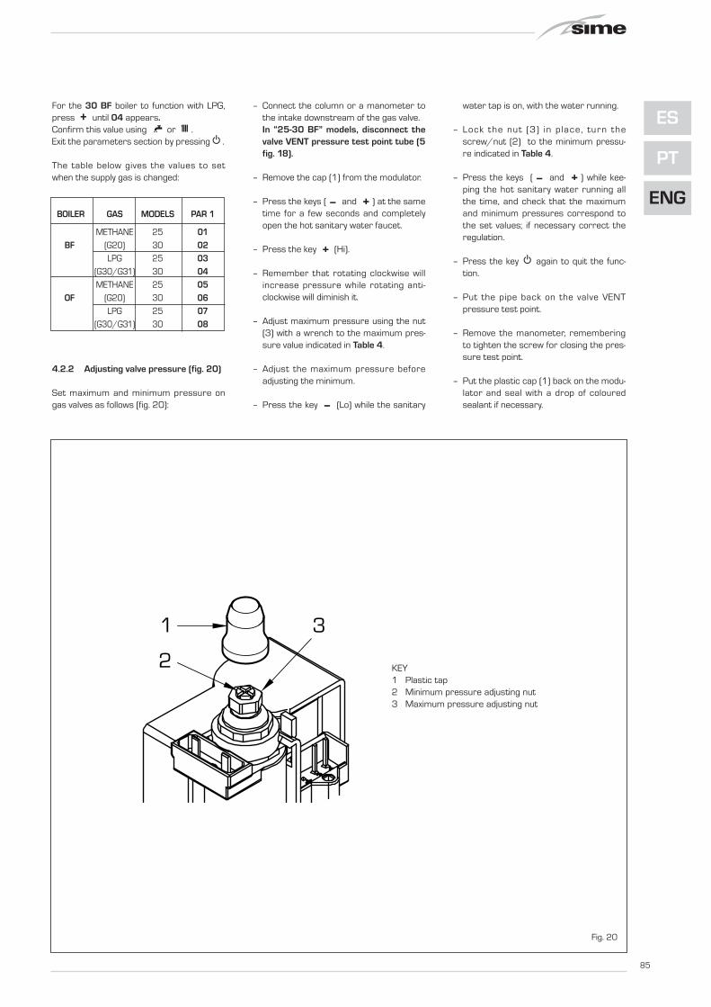
4.2.2 Adjusting valve pressure (fig. 20)
Set maximum and minimum pressure ongas valves as follows (fig. 20):
– Connect the column or a manometer tothe intake downstream of the gas valve.In “25-30 BF” models, disconnect thevalve VENT pressure test point tube (5fig. 18).
– Remove the cap (1) from the modulator.
– Press the keys ( and ) at the sametime for a few seconds and completelyopen the hot sanitary water faucet.
– Press the key (Hi).
– Remember that rotating clockwise willincrease pressure while rotating anti-clockwise will diminish it.
– Adjust maximum pressure using the nut(3) with a wrench to the maximum pres-sure value indicated in Table 4.
– Adjust the maximum pressure beforeadjusting the minimum.
– Press the key (Lo) while the sanitary
water tap is on, with the water running.
– Lock the nut (3) in place, turn thescrew/nut (2) to the minimum pressu-re indicated in Table 4.
– Press the keys ( and ) while kee-ping the hot sanitary water running allthe time, and check that the maximumand minimum pressures correspond tothe set values; if necessary correct theregulation.
– Press the key again to quit the func-tion.
– Put the pipe back on the valve VENTpressure test point.
– Remove the manometer, rememberingto tighten the screw for closing the pres-sure test point.
– Put the plastic cap (1) back on the modu-lator and seal with a drop of colouredsealant if necessary.
BOILER GAS MODELS PAR 1
METHANE 25 01BF (G20) 30 02
LPG 25 03(G30/G31) 30 04METHANE 25 05
OF (G20) 30 06LPG 25 07
(G30/G31) 30 08
3
2
1
Fig. 20
KEY1 Plastic tap2 Minimum pressure adjusting nut3 Maximum pressure adjusting nut

86
4.3 DISMANTLING THE CASING (fig. 21)
The casing may be removed completely tofacilitate boiler maintenance, as shown infig. 21. Turn the panel control forward foraccess to the internal components of theboiler.
4.4 MAINTENANCE
To guarantee functioning and efficiency ofthe appliance, in respect of the legal pro-visions in force, it must be regularlychecked; the frequency of the checksdepends on the type of appliance and theinstallation and usage conditions.In any case, it should be inspected atleast once a year by a qualified technician.
Carry out the cleaning of the generator in
the following way:– Turn the main switch off to stop electric
power reaching the boiler and close thegas feed cock.
– Remove the outer casing and the gasburner manifold unit. To clean the burner,blow in a jet of air, so as to remove anydust particles that may have accumula-ted.
– Clean the heat exchanger, removing anydust or residue from combustion. Whencleaning the heat exchanger or the bur-ners, chemical products or steel bru-shes MUST NOT BE USED.Make sure that the tops of the burnerswith the holes are free from encrusta-tions.
– Reassemble the items removed fromthe boiler, making sure to follow the cor-rect sequence.
– Check operation of the main burner.– After assembly of all the gas connec-
tions, these must be tested for sound-ness, using soapy water or appropriateproducts. DO NOT USE NAKED FLAMES.
– Do not use calcium chloride to treat theplastic component during generatormaintenance.
4.4.1 Chimney sweep function
To check boiler combustion, press at thesame time the installer's key ( e ) fora few seconds. The chimney sweep function will switch onand will continue for 15 minutes. During the 15 minutes functioning of chim-ney sweep function, pressing the keys (and ) take the boiler respective at maxi-mum (Hi) and at minimum (Lo) power. From that moment, the boiler will startworking in heating mode at maximumpower, with cut off at 80°C and re-ignition
1
24 xFig. 21
Codice/Code 8109200Modello/Model FORMAT DGT 25 BFMatricola/Serial n. 9999999999
PAR 1 = 01 (G20)/ 03 (G30 -G31)PAR 2 = 09

87
ES
PT
ENG
at 70°C.Before activating the chimney sweep func-tion make sure that the radiator valves oreventual zone valves are open.The test can also be carried out with theboiler working in D.H.W. mode. For this, after activating the chimney sweepfunction, open one or more hot water fau-cets. Under these conditions, the boiler will func-tion at maximum power with the D.H.W.kept at between 60°C and 50°C. During the test, the hot water faucetsmust remain open.For exit to the chimney sweep functionpress the key of the control panel.
The chimney sweep function will automa-tically switch off after 15 minutes fromthe activation.
4.5 FUNCTIONING ANOMALIES
When there is a functioning anomaly, analarm appears on the display and switchon the red led.
Descriptions of the anomalies with relativealarms and solutions are given below:
– FUMES DISCHARGE ANOMALYALARM 01 (fig. 24)OPEN BOILER (OF):The display shows “AL 01”.The fumes thermostat has intervened.The boiler stops for an enforced periodof 10 minutes. At the end of this period, the boiler re-attempts ignition. If the anomaly is repeated three times in24 hours, the boiler blocks. Press the key of the controls tostart up the boiler again.
SEALED BOILER (BF):The fumes thermostat has intervened. Ifthe condition causing the problem persi-sts for two minutes, the boiler stops foran enforced period of thirty minutes. At the end of this period, the boiler re-attempts ignition.
– LOW WATER PRESSURE ANOMALYALARM 02 (fig. 24/a)If the pressure detected by the waterpressure valve is lower than 0.5 bar, theboiler stops and the display shows thealarm “AL 02”. Bring the pressure back to normal bymeans by acting on the telescopic loa-ding knob.Lower the knob and turn it anti-clockwiseto open until the pressure indicated onthe hydrometer reaches 1 - 1.2 bar.WHEN FILLING HAS BEEN COMPLETED,CLOSE THE KNOB BY TURNING ITCLOCKWISE.If the load procedure has to be repea-ted several times, it is advisable tocheck that the seal of the heating cir-cuit is intact (check that there are noleaks).
– D.H.W. SENSOR ANOMALY ALARM 04 The D.H.W. probe is not envisioned inthese boiler models; if the display showsthe AL 04 anomaly, check PAR 2.
– HEATING SENSOR ANOMALY ALARM05 If one or both sensing elements of hea-ting sensor (SM1/SM2) are open orshort circuited, the boiler will not func-tion and the display will show the alarm“AL 05”.
– FLAME BLOCK ALARM 06 (fig. 24/b)If the flame control has not detected the presence of the flame after a completeignition sequence, or for any other rea-son the card cannot “see” the flame, theboiler will stop and the display will showthe alarm “AL 06”. Press the key of the controls to startup the boiler again.
– SAFETY THERMOSTAT ANOMALYALARM 07 (fig. 24/c)If the C.H. sensor (SM1/SM2) exceedsthe 100°C the boiler does not ignite theburner, the display show AL 07 andremains ignited the green led. If this con-dition restored more one minute, theboiler will stop, the display show alwaysthe anomaly AL 07 and switch on thered led. Press the key of the controls to startup the boiler again.
– PARASITE FLAME ANOMALY ALARM08 If the flame control section recognisesthe presence of flames also in phaseswhen they should not be present, itmeans there is a breakdown in the flamedetection circuit; the boiler will stop andthe display will show anomaly “AL 08”.
– AUXILIARY SENSOR ANOMALYALARM 10 ONLY FOR BOILER WITH SOLAR PLANTCOUPLING (PAR 2 = 10 or 14): D.H.W. inlet probe anomaly. When theprobe is open or short circuited the boi-ler looses the solar function and thedisplay shows anomaly AL 10.
– MODULATOR ANOMALY ALARM 11 The modulator is not connected. When during functioning the boilerdetects zero current to the modulator,the display will show anomaly “AL 11”.The boiler will function at minimumpower and the anomaly will be de-acti-Fig. 24
Fig. 24/a
Apre
0 4
1 32
bar
Fig. 24/b
Fig. 24/c
OPEN

88
vated when the modulator is reconnec-ted or when the burner stops working.
– CONFIGURATION ANOMALY ALARM12 Anomaly in the SEALED/OPEN configu-ration. There may be a conflict betweenthe values set by the installer for PAR 1and the self-detection carried out by thecard causes the activation of the alarm:the boiler will not function and the displaywill show anomaly “AL 12”. Reset PAR 1 to de-activate the alarm orcheck the pressure switch/combustionproduct thermostat and relative connec-tion.
– HEATING PROBE POSITIONINGANOMALY SM1/SM2 “AL 16” (fig. 24/d)If the probe does not detect a tempera-ture increase after burner ignition, theburner switches off after 10 seconds,the display shows anomaly AL 16 eandthe4 green LED stays on. If the anomaly occurs three times within24h lthe boiler blocks, the display conti-nues to show anomaly AL 16 and the redLED switches on. Press on the control panel to re-startthe boiler.
– SENSOR ALIGNMENT ANOMALY “AL17”When the two sensitive elements of theheating probe (SM1/SM2) dif fer toeach other by more than 16°C the boilerdoes not function and the display showsanomaly AL 17. Reaplace the heat ing probe(SM1/SM2) to restore functioning.
Fig. 24/d

USER INSTRUCTIONS
WARNINGS– In case of fault and/or incorrect equipment operation, deactivate it, without making any repairs or taking any direct action.
Apply only to qualified technical personnel.
– Boiler installation and any other assistance and/or maintenance activity must be carried out by qualified personnel per-
suant to Standard CEI 64-8. Under no circumstances, the devices sealed by the manufacturer can be tampered with.
– It is absolutely prohibited to block the intake grilles and the aeration opening of the room where the equipment is installed.
– The manufacturer shall not be held liable for any damage caused by improper use of the appliance.
– This appliance is not intended for use by persons (including children) with reduced physical, sensory or mental capabilities, or lack
of experience and knowledge, unless they have been given supervision or instruction concerning use of the appliance by a person
responsible for their safety. Children should be supervised to ensure that they do not play with the appliance.
LIGHTING AND OPERATION
BOILER IGNITION (fig. 25)
The first ignition of the boiler must be car-ried out by qualified technical personnel.Successively, if it is necessary to start upthe boiler again, adhere strictly to the fol-lowing instructions: open the gas tap toallow the flow of the fuel and move the mainswitch of the system to “ON”. After a stop,wait for about 30 seconds before restoringfunctioning conditions do that the boiler canperform the control sequence.If the green led is on, this indicates the pre-sence of voltage.
Keys lock
If the device is not used, the keys will belocked 15 minutes after the last setting wasmade (PAR 5 by default) and the display light
switches off.To set one of the operating modes, pressany of the keys for more than two seconds(the display will indicate one to four seg-ments progressively before unlocking thecontrols).
Winter
Press the key of the controls to activa-te the winter mode functioning (heating andD.H.W.). The display will be as shown in thefigure.
Summer
Press the key of the controls to activa-te the summer mode functioning (only theproduction D.H.W.). The display will be asshown in the figure.
REGULATION OF THE WATER TEMPERA-TURE FOR HEATING (fig. 26)
To set the temperature of the water for
89
ES
PT
ENG
Fig. 25
ATTENTION: for set up modality of function more adapted to graze the keys sim-ply. One beep indicates that the boiler has taken command. If PAR 5 is disabled,the display remains lit.

90
heating, press the key of the controls . The display will be as shown in the figure.Change the values with the key ( and
). Standard visualisation will return tothe display by pressing the key again, orafter 10 seconds if no key is pressed.
Regulation of the external sensor (fig. 26/a)
If an external sensor is installed, the valueof the output temperature is automaticallychosen by the system, which quickly adjuststhe of flow temperature on the basis of theexternal temperature.If you wish to change the value of the tem-perature, increasing or decreasing that cal-culated automatically by the electroniccard, proceed as indicated in the precedingparagraph. The level of various correction of a value oftemperature proportional calculated. Thedisplay will be as shown in fig. 26/a.
REGULATION OF THE D.H.W. TEMPERATURE (fig. 27)
To set the desired temperature D.H.W.,press the key of the controls. The display will be as shown in the figure.Change the values with the key ( and ).The display will return to the standardvisualisation by pressing the key again,or after 10 seconds if no key is pressed.
TO SWITCH OFF THE BOILER (fig. 28)
In the case of a short absence, press morethan two second the key of the controls.The display will be as shown in figure (boilerin stand-by). In this way, leaving the electri-city and the fuel supply connected, the boi-ler is protected from frost and from thepump becoming blocked.If the boiler is not used for a prolongedperiod, it is advisable to disconnect theelectricity supply, by switching off the mainswitch of the system, and to close the gastap and, if low temperatures are expected,to completely empty the hydraulic circuitsto avoid pipes being broken by the forma-tion of ice in the pipes.
Fig. 26
Fig. 26/a
Fig. 28
Fig. 27

91
ES
PT
ENG
ANOMALIES AND SOLUTIONS
When there is a functioning anomaly, thedisplay controls shows and red led switchon.Descriptions of the anomalies with the rela-tive alarms and solutions are given below:
– AL 01 (fig. 29)Press the key of the controls to re-start the boiler.If the anomaly persists, request theintervention of qualified technical per-sonnel.
– AL 02 (fig. 29/a)If the water pressure detected is lowerthan 0.5 bar, the boiler will stop and thedisplay will show “AL 02”.Bring the pressure back to normal bymeans by acting on the telescopic typeloading knob. Lower the knob and turn it anti-clockwiseto open until the pressure indicated bythe hydrometer is between 1 and 1.2bars.WHEN FILLING HAS BEEN COMPLETEDCLOSE THE KNOB TURNING ITCLOCKWISE.
If it is necessary to repeat the systemloading procedure, it is advisable tocontact qualified technical personnelto check the seal of the heating system(to check whether there are any leaks).
– AL 04Request assistance from qualifiedtechnical personnel.
– AL 05Request assistance from qualifiedtechnical personnel.
– AL 06 (fig. 29/b)Press the key of the controls to re-start the boiler.If the anomaly persists, request assi-stance from qualified technical person-nel.
– AL 07 (fig. 29/c)Press the key of the controls to re-start the boiler.If the anomaly persists, request assi-stance from qualified technical person-nel.
– AL 08Request assistance from qualifiedtechnical personnel.
– AL 10Request assistance from qualifiedtechnical personnel.
– AL 11Request assistance from qualifiedtechnical personnel.
– AL 11Request assistance from qualifiedtechnical personnel.
– AL 12Request assistance from qualifiedtechnical personnel.
– AL 16 (fig. 29/d)Press the key of the controls to re-start the boiler.If the anomaly persists, request assi-stance from qualified technical person-nel.
– AL 17Request assistance from qualifiedtechnical personnel.
GAS CONVERSION
If it is necessary to change to a differenttype of gas, request assistance only fromauthorised technical personnel.
MAINTENANCE
Annual maintenance of the applianceshould be planned sufficiently in advance,requesting the assistance of authorisedtechnical personnel.The boiler is supplied with an electric wirefor the electrical power supply which, inthe case of replacement, must be substi-tuted only by another obtained from theconstructor.
Fig. 29
Fig. 29/a
Apre
0 4
1 32
bar
OPEN
Fig. 29/b
Fig. 29/c
Fig. 29/d

Fonderie Sime S.p.A - Via Garbo, 27 - 37045 Legnago (Vr) Tel. + 39 0442 631111 - Fax +39 0442 631292 - www.sime.it
Doc
umen
tati
on D
pt. F
onde
rie
Sim
e S
.p.A
.