flow instability of centre-body diffusers at supersonic...
TRANSCRIPT

MINISTRY OF SUPPLY
R. & M. ~ No. 2933 (14,519 and 16,599)
A.R.C. Technical Report
e , ) \,~
~ - . - ":,%
AERONAUTICAL RESEARCH COUNCIL REPORTS AND MEMORANDA
Flow Instability of Centre-body Diffusers at Supersonic Speeds
By
D. BEASTALL
Crown Copyright Reserved
LONDON: HER MAJESTY,S STATIONERY OFFICE
1956
PRICE 3s 6d NET

Flow Instability of Centre-body Diffusers at Supersonic Speeds
By
D. BEASTALL
COMMUNICATED BY THE PRINCIPAL DIRECTOR OF SCIENTIFIC RESEARCH (AIR),
MINISTRY OF SUPPLY
Reports and Memoranda 2Vo.
November, 19 5 3
2933
Summarv.--This note offers explanations for certain types of flow instability which occur with centre-body diffusers at supersonic speeds. These instabilities manifest themselves as oscillations of the shock pat tern ahead Of the diffuser and the flow through the diffuser for certain conditions of operation and are likel.y to affect seriously the performance. Two main types of oscillation have been distinguished : a violent oscillation which occurs when the flow through the diffuser is throttled below a certain value ; a less severe oscillation which occurs when the vortex sheet from the inter- section of the shock waves ahead of the diffuser or a separated boundary layer strikes the cowl.
The explanations of the oscillations are substantiated by schliere'n photographs of two- and three-dimensional modeI diffuser tests in a wind tunnel. I t seems possible, in the light of the explanation given in this note, to be able to predict the range of instability of any centre-body diffuser configuration by fairly simple model tests.
1. Introduction.--Although centre-body diffusers and intakes are more desirable at high supersonic Mach numbers than pitot-type intakes on account of the improvement in pressure recovery, they are often prone to violent flow oscillations for part or all of the mass flow range. The nature of the flow oscillations is complex but two main types can be recognised. One we shall call the large oscillation and the other the small or ' organ-pipe ' oscillation.
According to the explanations offered the large oscillation is determined by the relative positions of the centre-body and cowl, and can be avoided by judicious positioning of one to the other. The small oscillation is caused by resonance of the air in the diffuser and can also be avoided by paying attention to the dimensions o.f the cowl and centre-body. An explanation of the mechanisms which cause these flow oscillations, and suggestions for avoiding them, will be given in this note. Unfortunately in many cases stable flow over a large range of mass flows can only be obtained by incurring a rise in spillage drag.
The conclusions regarding the flow oscillation were reached as a result of a series of wind-tunneI tests designed solely for the purpose of studying the oscillations. Most of the tests were made at M = 1.8 with two- and three-dimensional ducted bodies. Some relevant schlieren photo- graphs of observations of these tests are presented to substantiate the explanations of the flow instability. The photographs were taken with an exposure time of T}5 sec and oscillating unstable flows show up as blurred images, the only clearly defined shock positions being the limits of the oscillation.
* R.A.E. Tech. Note Aero. 2128--received 22nd December, 1951. R.A.E. Tech. Note Aero. 2128a--received 25th February, 1954.
A
1

2. Mechanism of the Large Flow Oscillation.--Fig. 1 shows a typical centre-body diffuser designed to have the conical shock on the cowl lip at full mass flow for a free-stream Mach number M ; there will then be no spillage drag and the flow is quite stable. As the mass flow through the diffuser is reduced, the flow configuration at the entry has to adjust itself to satisfy the new requirement. Fig. 2 shows such a configuration with air being spilled round the ou t s ide of the cowl with a three-shock configuration ahead of the diffuser. The' flow is modified slightly by the presence of a boundary layer on the centre-body which will separate to some extent depending on the strength of the shock intersecting it and also on the state of the boundary layer itself. As the mass flow is reduced the curved shock moves forward to allow more and more spillage but a point is reached at which the shock can move no further forward. This is the shock position which corresponds to the detached shock which would form ahead of the Cowl if it were a solid body. To make a further reduction in mass flow through the diffuser entry the flow configuration ahead of the entry must now change to some other form.
The only other form of flow appears to be the type shown in Figs. 9 and 10 where the spillage is adjusted by flow separation from the centre-body. As more and more spillage is required, the point of separation moves further and further forward. Unfortunately for many diffusers neither type of flow configuration at the entry is able to satisfy the mass flow requirement and at tempted operation in such a case results in a violent flow oscillation which alternates between the two types of flow pattern. The oscillation can usually be heard as a shrill whistle.
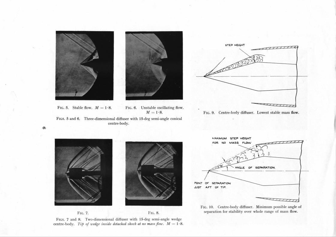
From the previous explanation it can be seen that the limits of stabil i ty for a given centre-body diffuser can be defined as follows. A diffuser (with a conical centre-body) will always be stable throughout the full mass flow range as long as the tip of the centre-body cone is within the detached shock that lies ahead of a solid body of the same shape as the cowl. This will ensure tha t any spillage can be effected by the three-shock configuration sinee the curved shock can move right up to the tip of the cone. If the tip of the centre-body lies ahead of the detached shock (as de- fined above) the diffuser is liable to flow oscillations unless the flow can be adjusted by spillage due to separation of flow from the centre-body. The limit of this type of configuration--and this determines the forward limit of centre-body position relative to the cowl--is when the point of separation has to move so far forward in order to give the required spillage tha t it reaches the tip of the cone. To effect any further spillage implies that the point of separation will have to move ahead of the tip which is impossible. Fig. 9 shows the lowest mass flow configuration for a given centre-body and cowl. For stabil i ty over the whole range the angle of separation would have to be as shown in Fig. 10. This type of flow is similar to the flow over steps which has been examined in an unpublished R.A.E. report,'the angle of separation being a function of Mach number, the state of the boundary layer on the body and step height as defined in Figs. 9 and 10.
Thus to ensure that a given cowl and centre-body will be stable throughout the range of full to no mass flow the tip of the cone must not lie in the range of positions relative to the cowl which are defined by : the detached shock in front of a solid body of the same shape as the cowl as the rearmost limit, and the point at which complete spillage can just be effected by separation from the centre-body as the foremost limit. T h e s e limits are shown in Fig. 11.
Some typical examples of stable and oscillating unstable flows which substantiate the previous explanation are presented in the form of schlieren photographs. These photographs were taken with a To~-Sec exposure and give a blurred image when there is an oscillatory flow, a stable flow giving a comparatively well-defined image. Fig. 3 shows a stable flow with spillage being effected by separation. The point of separation can be seen about half-way along the wedge. If now the wedge is withdrawn into the cowl, a flow oscillation starts when the point of separation has moved to the tip. The resulting schlieren photograph of this type of oscillation is shown in Fig. 4. The photograph gives a blurred image of the flow configuration during several oscillations. Although at some instant the flow configuration may be similar to that of Fig. 3 the high frequency of the oscillation compared with the exposure time obscures the fact. Similar examples are given in Figs. 5 and 6 for a three-dimensional diffuser. Once again the stable flow shown in Fig. 5 gives a well-defined image of the separation from the conical Centre-body. In Fig. 6 tile nebulous picture of the flow just ahead of the diffuser is a result of the oscillatory flow.
2

Figs. 7 and 8 show a two-dimensional diffuser wtiich is stable for the whole range of mass flows. Here, the tip of the wedge lies within the detached shock that lies ahead of the solid body of the same external dimensions as the cowl and spillage can therefore be effected by the three- shock configuration.
3. Suggested Experime~#al Work to Provide Data for Designing Diffusers which are Stable with Regard to the Large Oscillatio~.--We have suggested that flow oscillation can occur on a centre- body diffuser if the tip of the cone or wedge comprising the centre-body lies within the positions defined as follows : the rearward limit is the detached shock which would form in front of tile cowl if it was a solid body ; the forward limit is the position of the centre-body such that separation of the boundary layer from the centre-body can take place so as to spill all the flow outside the cowl. These two limits are denoted in Fig. 11.
These limits can be found experimentally for any cowl and centre-body. Fig. i2 suggests a typical wind-tunnel test arrangement for determining the limits for a series of centre-bodies and a given cowl shape. A trace of the detached shock which occurs at a given Mach number in front of the bluff body of cowl shape will define the rearward limit and by pushing forward the cone the forward stable position can be obtained.
For a given position of the centre-body relative to the cowl, the limiting three-shock con- figuration Call be constructed by drawing the detached shock trace in front of the cowl and the conical shock from the nose of the centre-body thus obtaining the three-shock intersection point.
Since boundary-layer separation phenomena are known to be affected by Reynolds number changes, a full experimental programme to determine the range of instability should include a study of such changes.
4. Mecha~isrn of the Small Flow Oscillation.--The previous sections have defined the design of a diffuser which will be stable as far as the large oscillation is concerned. Such a diffuser, however, is still likely to be susceptible to a small oscillation. This small oscillation appears to be caused by resonance of the column of air in the diffuser which vibrates as in an organ pipe causing fluctuations of pressure at the mouth of the diffuser. This in turn causes the flow ahead of the entry to oscillate over a small range. This oscillation is illustrated by tile schlieren of Figs. 13 and 14. The diffuser is operating at no mass flow in both cases and the only difference in construction (as shown by the diagrams) is that tile air space between the centre-body and cowl differs in the two cases (i.e., tile centre-body diameters are different). There is stable flow through one diffuser (Fig. 14) but the flow oscillates ahead of the other (Fig. 13). In Fig. 14 the point of separation of the flow from midway along the wedge is dear ly defined. In Fig. 13 this separa- tion is not visible. In fact the point of separation is oscillating over some length of the wedge and the resultant picture is accordingly blurred. It may be noticed that this oscillation does not interfere with the shock at the tip of the wedge as the large oscillation did, but this distinction need not always apply.
The oscillation can be cured by altering the dimensions of tile air space in the diffuser either in length or breadth which suggests that the exciting force will only excite a given frequency. The exact nature of the exciting force is not fully understood at present but the following explana- tion is suggested as being probable. In organ pipes the resonance of the air column is sensitive to the length of the air jet playing on the edge of the pipe, the resonance being produced by the ' edge tone ' thus produced. In a similar way the edge tone of the diffuser cowl may be excited by the separated boundary layer acting as a jet, or (in another instance when the oscillation occurs) when the vortex sheet from the intersection of tile three-shock configuration plays on the lip of the cowl. The length of the jet in these cases would be the length of the separated boundary layer or vortex sheet.
Brief tests were made to see if the oscillation could be excited by natural frequency oscillations of the cowl or model support but in both cases altering the stiffness did not stabilise the flow.
3

Further tests are required to examine more closely this type of oscillation and the method by which it is excited. In devising these experiments it is likely that the natural frequency of the air in the diffuser will be sensitive to temperature changes and will therefore depend on whether burning is taking place.
Even without further knowledge of the mechanism of the oscillation it should be possible to avoid any oscillation for a given design of diffuser by altering tile dimensions of the air space or by ensuring tha t the cowl is not subject to a jet in the form of either a separated boundary layer or a vortex sheet issuing from a shock intersection.
5. Comlusions.--This report has offered an explanation of the large and small flow oscillations which can occur with centre-body diffusers at supersonic speeds and the results of some wind- tunnel tests have been given in support.
Wi th an understanding of the mechanism of the large flow oscillation it is possible to design a diffuser which will be stable or in which the limits of stable operation can be found.
Although a diffuser may be stable as regards the large oscillation it may still be vulnerable to a small oscillation. The mechanism of this oscillation is not fully known but methods of avoiding it in practical cases are suggested.
4

l fjd" ~
i,
c~
° , , ~
o ~
c~
c~
$ A!
S'v-=.P MtI~VCI" ~.._.m-y-,w-WT-W-r~
FIG. 5. Stable flow. M = 1"8. FIG. 6. Unstable oscillating flow. M = 1.8.
FIGS. 5 and 6. Three-dimensional diffuser with 15-deg semi-angle conical centre-body.
FIG. 9. Centre-body diffuser.
~ 1 t" t" t ' 1 1 ~
Lowest stable mass flow.
FIG. 7. FIG. 8.
FIGS. 7 and 8. Two-dimensional diffuser with 15-deg semi-angle wedge centre-body. Tip of wedge inside detached shock at no mass flow. M = 1.8.
IWI.~,~UVlUI~4 STF..P H E ~ H T
~'OR NO Iw~,,~S ~'I.,OW ~ . . . . - - - r - , ' , ' f 7 d ," ," " " /~.,~
OUST" A F T 0¢' "liP.
L / t" t - / , , - ~
FIG. 10. Centre-body diffuser. Minimum possible angle of separation for stability over whole range of mass flow.

SHOCK.
FLOW O~ .I/ ..~.w~//~///////////////// SEPARATIDM / /
/ / /
/ / . . / "
j l I
FIG. 11.
CENTRE B Ol::)Y CENTRE POSITION POSITI ON
LJNSTA~LE
F L O W i --.ml
~TABLE.
~ - - " - - ~ . . ~ L Z / / / / / / / / / / / / / / / / /
STAB, LE. \
Centre-body diffuser. Limits of position of centre-body for unstable flow.
E:5 S E M I
IO ~ ,,~F..M I - ANq
IS°S~ a o ~ SE~4,~__
NOTE :-- ALL CONES OF SANE LENGTH
/ i~,LUFF BODY OF S A M E OUTSIDE IDIMEN.~ONS A.~ COWL
L E CF_..~JTRE'RO~
FIG. 12.
I I
Typical test arrangement for determining forward stable position of centre-body. (Axi-symmetricaI diffuser.)

0o
~ / ~ III//ll//lllllll _ _
lllllllllllll
,-~ I .oV _ ] _ z.o" ~!
FIG. 13. Centre-body diffuser. Small flow oscillation.
FIG. 14. Centre-body diffuser. Stable flow.

A F U R T H E R NOTE
1. A Further Discussion of the Large Oscillation which Occurs in Conical Centre-body fntake 01heration.--There appears to be some misunderstanding of the explanation of the large oscillation which occurs in conical centre-body intakes as presented in the first part of this report. Goldsmith and Griggs in an unpublished report quote the first part as having said that ' the flow breakaway (on the centre-body) would need to move forward to the cone tip before causing oscillation' and quite rightly point out tha t this is not always the case.
But this is not what that paper says and what in fact is suggested is that the oscillation is liable to occur when neither of two certain types of flow configuration at the inlet can be satisfied. These two stable types of flow are shown in Figs. 1 and 2. In Fig. la the full lines represent the conical shock from the tip of the centre-body intersecting with a curved shock similar to the detached shock which appears in front of bluff bodies ; from the point of intersection a nearly normal shock stretches and intersects with the boundary layer on the centre-body. Some separation might be expected from such a shock-wave boundary-layer interaction and does in general take place, the extent depending on the strengt h of the shock--but this separation is not the mechanism whereby the flow through the inlet is adjusted. With th i s type of flow pattern adjustment of the spillage, as the inlet is throttled, is effected by fore-and-aft movement of the curved shock position. Thus the dash lines in Fig. la might be the shock pattern for a reduced mass flow through the inlet. In this method of adjusting the spillage, oscillation may occur before the point of flow separation reaches the tip of the cone. The first part of this report specifies that this particular method of adjusting the flow can only work up to the point where the curved shock has reached a position which corresponds to the position a detached shock would take up if the inlet were a solid body (without tile conical centre-body). Thus the position of the shock in Fig. lb where the solid body is the same shape as the external shape of the cowl in Fig. la will give the limit of flow adjustment when superimposed on Fig. la, for the par- ticular Mach number being considered. This condition is shown in Fig. lc. Any further throt t l ing of the inlet will lead to oscillatory flow.
Now let us consider the other flow pattern in Fig. 2. This usually occurs when the centre-body projects a long way in front of the cowl. Here there is separation from the centre-body with a shock and there is a further shock attached to the cowl lip. In this case adjustment of the flow through the inlet is effected by fore=and-aft movement of the point of separation along the centre-body to adjust the amount of spillage, the shock at the cowl lip remaining nearly attached throughout. I t is in this case tha t the first part of this report suggests that the flow becomes oscillatory when the point of separation reaches the cone tip, for to spill more air would imply that the point of separation should move ahead of the tip.
Now consider a particular arrangement of cowl and centre-body as for example shown in Fig. 3a where we want to know under what conditions, if any, there will be flow oscillations. In Fig. 3b is shown the detached shock ahead of a solid body of the same dimensions as the external cowl shape. If we superimpose this shock pattern on Fig. 3a the shock cuts the centre-body and the pattern can be completed by drawing in the conical shock from the cone tip and the shock from the point of intersection to the centre-body (Fig. 3c). This gives the flow pat tern with maximum possible spillage without oscillations occurring.
If, however, the second type of flow pattern occurs over the nose of the in le t - -and it migh t be possible for both types of flow to be practically possible in some cases--then Fig. 3d will give tile general flow pattern and Fig. 3e the conditions for maximum spillage before oscillations occur (i.e., with the point of separation at the tip of the cone).
In the first part of this report the treatment of the problem was to specify the two positions of the centre-body in relation to a cowl between which flow oscillations were likely to occur. Thus the configuration in Fig. l a would be liable to oscillatory flow but this would not occur until the mass flow through the inlet was reduced so that the limiting condition of Fig. lc was reached. Similarly the configuration of Fig. 2 would be liable to oscillatory flow if complete
9

spillage could not be effected before the point of separation reached the tip of the cone a n d here again the oscillation would not occur until this condition was reached. It can be seen tha t the flow pattern for the limiting stable flow can be constructed simply from a knowledge of the shock of Fig. lb and the conical shock from the cone tip if the first type of flow pattern exists ; and with more difficulty the limit for the second type of flow can also be constructed if the angle of separation from the centre-body is known. The first type of flow pa t t e rn can be constructed from existing knowledge ; the second type requires further experiment.
10

/ /
\ \ 'SF-p~RA'I'IQN r_~LI~F_D I~Y SI-IO~'KWAVE \ X BOUNDARY LAYER INTERACTION.
/ /
\ FI,.O N 5EPAR
FIG. la. FIG. lb. FIG. lc.
FIGS. la, lb and lc. The flow pattern at a conical centre-body inlet
°.HOQK- NAV~" .~
FIG. 2. Alternative flow pattern at a conical centre-body inlet

"7-
t ~
b~
/
\
FIG. 3a.
Y
FIG. 3b.
FIG. 3C.
FIGS 3a. to 3e.
FIG. 3d.
. . . . - . . . . . . . . . . 1
FIG. 3e.
Tile limiting flow patterns for non-oscillatory flow.

R. & M.: No. 2933
Publications of the Aeronautical Research Council
ANNUAL TECHNICAL REPORTS OF THE AERONAUTICAL RESEARCH COUNCIL (BOUND VOLUMES)
I938 Vol. I. Aerodynamics General, Performance, Airscrews. 5os. (5IS. 8d.) Vol. II. Stability and Control, Flutter, Structures , Seaplanes, Wind Tunnels, Materials. 3os. (3 ! s. 8d.)
1939 Vol. I. Aerodynamics General, Performance, Airscrews, Engines. 5os. (5IS. 8d.) Vol. II. Stability and Control, Flutter and Vibration, Instruments, Structures, Seaplanes, etc.
63 s. (64s. 8d.)
I94oAero and Hydrodynamics, Aerofoils, Airscrews, Engines, Flutterl icing, Stability and Control, Structures, and a miscellaneous Section. 5os. (51s. 8d.) /
1941 Aero and Hydrodynamics, Aerofoils, Airscrews, Engines, Flutter, Stability and Control, Structures. 63 s. (64 s. 8d.)
1942 Vol. I. Aero and Hydrodynamics, Aerofoils, Airscrews, Engines. 75s. (76s. 8d.) Vol. II. Noise, Parachutes, Stability and Control, Structures, Vibration, Wind Tunnels. 47 s. 6d.
(49 s. 2d.)
1943 Vol. I. Aerodynamics, Aerofoils, Airscrews. 8os. (8is. 8d.) Vol. II. Engines, Flutter, Materials, Parachutes, Performance, Stability and Control, Structures.
9os. (9IS. Iid.)
1944 Vol. I. Aero and Hydrodynamics, Aerofoils, Aircraft, Airscrews, Controls. 84 s. (86s. 9d.) Vol. II. Flutter and Vibration, Materials, Miscellaneous, Navigation, Parachutes, Performance,
Plates and Panels, Stability, Structures, Test Equ!pment, Wind Tunnels. 84 s. (86s. 9d.)
ANNUAL REPORTS OF THE AERONAUTICAL RESEARCH' COUNCIL-- 1933-34 IS. 6d. (IS. 8½d.) 1937 2s. (2s. 2½d.) 1934-35 IS. 6d. (IS. 8½d.) 1938 IS. 6d: (IS. 8½d.)
April I, 1935 to Dec. 31, 1936 4 s. (4 s. 5½d.) 1939-48 3 s. (3 s. 3½d.)
INDEX TO ALL REPORTS AND MEMORANDA PUBLISHED IN THE ANNUAL TECHNICAL REPORTS, AND SEPARATELY--
April, 195o . . . . . R. & M. No. 26o0. 2s. 6d. (2 s, 7½d.)
AUTHOR INDEX TO ALL REPORTS AND MEMORANDA OF THE AERONAUTICAL RESEARCH COUNCIL--
I9o9-January, 1954 - - - R. & M. No. 2570. 15 s. (I5 s. 5½d.)
INDEXES TO THE TECHNICAL REPORTS OF THE AERONAUTICAL RESEARCH C O U N C ~
December i, 1936 - - June 30, 1939. R. & M. No. 185o. is. 3 d. (Is. 4½d.) July i, 1939 - - June 30, 1945. - R. & M. No. 195o. is. (is. I½d.) July i, 1945 - - J u n e 30, 1946. - R. & M. No. 2050. is. (is. I½d.) July z, 1946 - - December 31, 1946. R: & M. No. 215o. is . 3 d. (is. 4½d.) January I, 1947 - - June 30, 1947. - R. &M. No. 2250. is. 3 d. (is. 4½d.)
PUBLISHED REPORTS AND MEMORANDA OF THE AERONAUTICAL RESEARCH COUNCIL--
Between Nos. 2251-2349. - - R. & M. No. 2350. is. 9 d. (IS. io½d.) Between Nos. 2351-2449. - - R. & M. No. 2450. 2s. (2s. i½d.), Between Nos. 2451-2549. - - R. & M. No. 2550. 2s. 6d. (2s. 7½d.) Between Nos. 2551-2649: - R. & M. No. 265o. 2s. 6d. (2s. 7½d.)
Prices in brackets include #ostage
H E R MAJESTY'S S T A T I O N E R Y OFFICE: York House, Kingsway, London W.C.2; 423 Oxford Street, London W.I (Posi Orders" P.O. Box 569, London S.E.I}; 13a Castle Street, Edinburgh 2; 39 King Street, Manchester 2; 2 Edmund Street, Birmingham 3; 109 St. Mary Street,
Cardiff; Tower Lane, Bristol 1; 80 Chlchester Street, Belfast, or through any bookseller
S.O. Code No. 23-2933
R. & M. No. 2933