flight manual aircraft type: “aeroprakt-22l flight... · · 2011-12-29approved chief designer...
TRANSCRIPT

APPROVED
Chief Designer
Aeroprakt Ltd.
Yuri V. Yakovlev
“___”___________ 2008
Flight Manual
aircraft type:
“AEROPRAKT-22L

2
Model: "AEROPRAKT-22L"
Serial No:
Registration:
Date of issue:
This aircraft is to be operated in compliance with information and limitations given herein.

3
RECORD OF REVISIONS
Any revision of the present manual, except actual weighing data, must be recorded in the following table
according to information from the Manufacturer.
New or amended text in the revised pages will be indicated by a black vertical line on the left hand mar-
gin, and the Revision No. and the date will be shown on the bottom left hand side of the page.
Rev.
No.
Affected
Section
Affected
Pages Date Approval Date
Date
Inserted Signature
1 2.2 17.07.08 Approval 17.07.08 17.07.08

4
LIST OF EFFECTIVE PAGES
Section Page Date Section Page Date

5
Table of Contents
1. Flight manual of AEROPRAKT-22L aircraft
Section Page
General 1 7
Limitations 2 7
Emergency procedures 3 15
Normal operation 4 18
Performance 5 23
Weight and centre of gravity 6 24
2. Maintenance manual of AEROPRAKT-22L aircraft
Section Page
Description of the aircraft and its systems 1 25
Aircraft care, operation and maintenance 2 42

6
1. FLIGHT MANUAL OF AIRCRAFT
AEROPRAKT-22L

7
1. GENERAL
1.1. Introduction
1.2. General information about the aircraft description
1.3. Aircraft three-view drawing
1.1. Introduction
The aircraft Flight Manual has been prepared to provide the pilots and instructors with information for the
safe and efficient operation of this aircraft.
1.2. General information about the aircraft
AEROPRAKT-22L (A-22L) is a two-seat, high-wing strut braced monoplane of "classic" aerodynamic
layout with closed cockpit, non-retractable landing gear with nose wheel. Rotax-912 engine with tractor
three-blade adjustable pitch propeller is located in the nose of the fuselage.
AEROPRAKT-22L is intended for flying in VFR, simple meteorological conditions.
The landing gear and thrust-to-weight ratio allow operation of the aircraft from strips (airfields) with
both grass and concrete runways.
Wing span 9.55 m
Length 6.23 m
Mean aerodynamic chord 1.4 m
Wing area 12.62 m2
Wing loading 43.11 kg/m2

8
1.3. AIRCRAFT THREE-VIEW DRAWING

9
2. LIMITATIO NS
2.1. Introductions
2.2. Airspeed
2.3. Airspeed indicator markings
2.4. Power plant
2.5. FLYdat – engine-monitoring instrument
2.6. Weight
2.7. Approved manoeuvres
2.8. Manoeuvring load factors
2.9. Flight crew
2.10. Kinds of operation
2.11. Instruments
2.12. Fuel
2.13. Other limitations
2.14. Limitation of engine operation at negative temperatures
2.1. Introduction
Section 2 includes operating limitations, instrument markings, and basic tables necessary for safe opera-
tion of the aircraft, its engine, systems and equipment.
2.2. Airspeed
Airspeed limitations and their operational significance are shown in table 1.
Table 1
Symbol Speed IAS Remarks
VNE Never exceed speed 210 Do not exceed this speed in any operation
VA Max. manoeuvring speed 150 Do not make full or abrupt control movement above this
speed, because under certain conditions the aircraft may
be overstressed by full control movement
VF Max. flap extended speed 115 Do not exceed this speed with full flap deflection
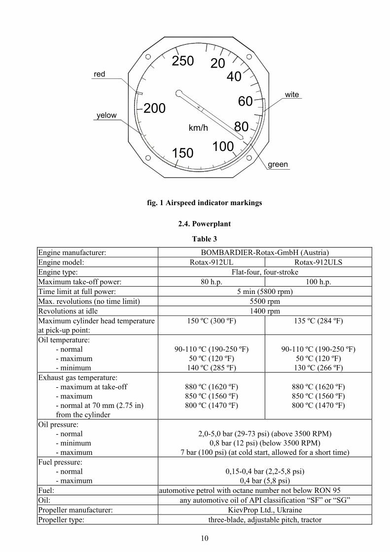
2.3. Airspeed indicator markings
Scheme of colour markings of air-speed indicator is shown below on fig. 2. Explanations are given in the
table:
Table 2
Marking IAS value or range Significance
White arc 60 - 115 Positive flap operative range
Green arc 70 - 150 Normal operating range
Yellow arc 150 – 210 Manoeuvres must be conducted with caution and only in smooth air.
Red line 210 Maximum speed for all operations
10
fig. 1 Airspeed indicator markings
2.4. Powerplant
Table 3
Engine manufacturer: BOMBARDIER-Rotax-GmbH (Austria)
Engine model: Rotax-912UL Rotax-912ULS
Engine type: Flat-four, four-stroke
Maximum take-off power: 80 h.p. 100 h.p.
Time limit at full power: 5 min (5800 rpm)
Max. revolutions (no time limit) 5500 rpm
Revolutions at idle 1400 rpm
Maximum cylinder head temperature
at pick-up point:
150 ºC (300 ºF) 135 ºC (284 ºF)
Oil temperature:
- normal
- maximum
- minimum
90-110 ºC (190-250 ºF)
50 ºC (120 ºF)
140 ºC (285 ºF)
90-110 ºC (190-250 ºF)
50 ºC (120 ºF)
130 ºC (266 ºF)
Exhaust gas temperature:
- maximum at take-off
- maximum
- normal at 70 mm (2.75 in)
from the cylinder
880 ºC (1620 ºF)
850 ºC (1560 ºF)
800 ºC (1470 ºF)
880 ºC (1620 ºF)
850 ºC (1560 ºF)
800 ºC (1470 ºF)
Oil pressure:
- normal
- minimum
- maximum
2,0-5,0 bar (29-73 psi) (above 3500 RPM)
0,8 bar (12 psi) (below 3500 RPM)
7 bar (100 psi) (at cold start, allowed for a short time)
Fuel pressure:
- normal
- maximum
0,15-0,4 bar (2,2-5,8 psi)
0,4 bar (5,8 psi)
Fuel: automotive petrol with octane number not below RON 95
Oil: any automotive oil of API classification “SF” or “SG”
Propeller manufacturer: KievProp Ltd., Ukraine
Propeller type: three-blade, adjustable pitch, tractor
200
250 2040
60
80
100150
km/h
wite
green
yelow
red

11
2.5. FLYdat - engine-monitoring instrument
A special combined instrument, FLYdat, is used for monitoring of engine operating parameters (fig. 3).
On FLYdat display, fig. 3, the following engine parameters data are indicated:
1 - RPM - engine speed,
1/min. revolutions per minute
2 - HOURS - hours of operation,
× 0.1 h 0.1 hour
3 - EGT/PTO - exhaust gas temperature, propeller side,
°C degrees Celsius
4 - EGT/MAG - exhaust gas temperature, magneto side,
°C degrees Celsius
5 - CHT - cylinder head temperature,
°C degrees Celsius
6 - EGT display - indicates the line of cylinders from which the EGT is picked up,
LEFT-RIGHT left or right
7 - OIL TEMP - oil temperature
°C degrees Celsius
8 - OIL PRESS - oil pressure
× 0.1 bar
The FLYdat instrument is programmed for the following:
- normal operation range, safe lower and upper limits;
- take-off mode and warn limits;
- each minimum and maximum value of alarm limit.
If the engine is running at speed less then 1,400 rpm then the red lamp “Battery discharge” is illuminated.
If all the engine parameters are within safe (normal range) limits then all their readings will be indicated
by steady (non-blinking) figures.
If one or more parameters are out of safe limits then their readings will blink. At the same time alarm in-
dicator will blink with period of 0.25 sec.
If one or more parameters are out of programmed alarm limits then their readings will be indicated by
blinking figures and alarm indicator will give a steady light.
ROTAX
RPM
1/min.
EGT/PTO
°C
× 0.1h
HOURS
°C
EGT/MAG
EGT display
LEFT-RIGHT
× 0,1 bar
OIL PRESS
CHT
°C
OIL TEMP
°C
fig. 2. FLYdat display.

12
2.6. Weight
Maximum take-off weight 544 kg
Maximum landing weight 544 kg
Empty weight 280±10 kg
Maximum luggage weight 20 kg
2.7. Approved manoeuvres
Aircraft "AEROPRAKT-22L" belongs to non-aerobatic category.
Manoeuvring should be within following limitations:
- steep turns with bank angles not more than 60 degrees (flaps up or down);
- sideslips with bank angles not more than 15 degrees at speed not exceeding 130 km/h.
2.8. Manoeuvring load factors
Limit load factors for the aircraft at gross weight of 544 kg are as follows:
Maximum positive limit load factor +3.5
Maximum negative limit load factor -1.5
2.9. Flight crew
The flight crew may include 1 or 2 pilots.
Flying the aircraft with a load in the luggage container heavier 20 kg is strictly FORBIDDEN.
2.10. Kinds of operation
The aircraft may be operated only in daytime, under VFR conditions and when there is no danger of icing.
It can be used for following missions:
- primary training;
- sport competition;
after installation of appropriate equipment it also can be used for:
- air surveillance and photography;
- any other application within the aircraft performance.

13
2.11. Instruments
fig. 3. Instrument panel layout
1 – airspeed indicator BK-240;
2 - altimeter BG-3E;
3 – vertical speed indicator BC-2A;
4 – artificial horizon;
5 – directional gyro;
6 – fuel level indicator (left tank);
7 – fuel level indicator (right tank);
8 – FLYdat;
9 – IGNITION switches;
10 – START button;
11 – additional equipment switch panel;
12 – fuse panel;
13 – cockpit heating handle;
14 – turn and slip indicator;
15 – air heater box control handle;
16 – engine ALARM indicator;
17 – NO BATTERY CHARGE indicator;
18 – MICROAIR transceiver.
2.12. Fuel
Table 4
Capacity of tanks 90 l
Total capacity 90 l
Usable fuel 89 l
Non-usable fuel 1 l
Fuel Petrol with RON 95 and above

14
2.13. Other limitations
This aircraft is approved as one of ultralight category and can be operated only in the day-time, under
VFR and when no icing is possible.
Wind limitation for "AEROPRAKT-22L" are as follows:
- head wind up to 10 meters per second;
- cross wind up to 4 meters per second;
WARNING!
• It is highly recommended to choose upwind direction for take-off and landing with the least
cross wind. It will significantly shorten take-off and landing distances and increase degree of
safety.
• All aerobatic manoeuvres including intentional spins are PROHIBITED.
2.14. Limitation of engine operation at negative temperatures
Engine Operator’s Manual prescribes some limitation of engine operation at negative temperatures.
At negative temperatures of ambient air icing of the carburettor, change in fuel-air mixture, loss of power
and freezing of fuel lines are possible. Negative temperature can affect the carburettor adjustment.
Operating temperature range for Rotax-912 engine is from -25 ºC to +50 ºC.

15
3. EMERGENCY PROCEDURES
3.1. Introduction
3.2. Engine failure
3.3. Restarting the engine in flight
3.4. Fire
3.5. Landing with engine stopped
3.6. Spin recovery
3.7. Pitot/static system failure
3.8. Radio failure
3.9. Flying in dangerous meteorological conditions
3.10. Landing out of airfield
3.1. Introduction
Section 3 contains recommendations to the pilots in case of emergency in flight. However such situations,
caused by airframe or engine malfunction are extremely rare provided that pre-flight inspections and
checks are made regularly.
3.2. Engine failure
1. In case of engine failure during take-off roll switch OFF the engine ignition system and discontinue the
take-off.
2. If the aircraft is at altitude up to 50 meters switch the engine OFF and land right ahead avoiding head-
on collision with any obstacles.
3. If the engine failed during climb, set the aircraft into a steady descent at a speed of 90 km/h and if the
altitude is sufficient turn the airplane toward the airfield, switch the ignition off, and make landing.
4. In case of engine failure during level flight set the aircraft into steady descent at a speed of 90 km/h,
switch the ignition off, estimate wind direction and strength, choose a place for landing and land (pref-
erably into the wind). Under favourable flight conditions try to restart the engine in flight (see para-
graph 3.3). If the altitude is not sufficient, land.
5. If there is no place for landing and conditions do not allow restarting the engine in flight, use the re-
covery system (installed as an option).
Recommendations to the crew.
While descending on the parachute of recovery system the aircraft may rotate. In connection with this the
crew is recommended to do the following:
- using ailerons and rudder try to stop the rotation.
- the pilots should adopt a safe position to avoid possible injuries from impact in case of rough landing.
3.3. Restarting the engine in flight
To restart the engine in flight:
- set the throttle lever at idle;
- set the ignition switches into ON position;
- turn the key to start the engine.
3.4. Fire
In case of fire on board crew should act as follows:
- shut off the fuel taps;
- switch the ignition OFF;
- set the aircraft into a steady descent;
- make emergency landing or deploy the recovery system.

16
3.5. Landing with engine stopped
This aircraft has no peculiar handling features during the landing with stopped engine and flaps up or
down. Recommended speed at descent - 90 km/h, entry into the flare at 5 meters, flare out at 0.5 m, land-
ing speed 60 km/h. Maximum gliding ratio for the aircraft is approximately 10.
3.6. Spin recovery
WARNING: Intentional spins on the aircraft are prohibited.
NOTE: In level flight and during turn stall approach warning is provided by the aerodynamic characteris-
tics of the aircraft - shaking of aircraft structure and control yoke.
To recover the aircraft from the spin (unintentional stall) push forward the rudder pedal opposite to the di-
rection of spin and then push the yoke fully forward. When the rotation ceases put the rudder in neutral
position and after reaching speed of 80 km/h smoothly level off the aircraft without exceeding the load
factor of +4 and maximum allowed speed of 200 km/h.
3.7. Pitot/static system failure
1. Pitot tube blockage
Signs of the malfunction:
- in level flight readings of airspeed indicator do not change with speed changing;
- during descent airspeed readings decrease and during climb increase.
Crew actions:
- Do not use airspeed indicator readings. In level flight set the engine speed to 4100-4300 rpm, the
airspeed at that will be 100-110 km/h. While descending reduce the engine speed to idle set the
sink rate of 4 m/s in this case the airspeed will be approximately 110 km/h.
2. Static tube blockage
Signs of the malfunction:
- readings of vertical speed indicator and altimeter do not change with altitude changing;
- during descent airspeed readings increase and during climb decrease.
Crew actions:
- Do not use readings of airspeed indicator.
- Check the airspeed by FLYdat (tachometer) readings only.
3.8. Radio failure
NOTE: Radio transceiver is installed as an option.
If there is no radio transmission/reception make sure that:
- the radio is switched on;
- the frequency is set correctly;
- headset cable is plugged into the radio set.
Crew actions:
- Set VOLUME to maximum, SQUELCH to OFF.
- Check the radio connection at other frequencies.
3.9. Flying in dangerous meteorological conditions
Flying in dangerous meteorological conditions means flying in conditions when icing is possible, during
thunderstorm, dust storm and strong turbulence.
Pay attention continuously to flight condition changes. If flight conditions begin to deteriorate take deci-
sion in time to change the route or discontinue the flight.
WARNING: Flying in conditions when icing is possible is FORBIDDEN! In case of getting into such
conditions the crew must leave the hazardous area immediately, and land at the nearest airfield or suitable
place.
17
WARNING: Flying in the vicinity of thunderstorm is FORBIDDEN!
Having noticed the thunderstorm area estimate the available time, the direction of thunderstorm approach-
ing and land at the nearest airfield or a suitable place. Tie down and cover the aircraft. The control sur-
faces must be secured with clamps or stops, the canopy must be locked reliably.
Strong turbulence may be very dangerous. Avoid it in flight taking in time the decision to change the
route or discontinue the flight.
In case of getting in strong turbulence at low altitude climb immediately to higher altitude flying away
from the source of turbulence.
During strong turbulence the airspeed must be not less then 100 km/h but not more then 140 km/h, alti-
tude at least 100 m. Turns must be performed with bank angle up to 30°.
In case when flying into turbulence can not be avoided choose an open field and land trying not to exceed
the limit values of speed and bank angle.
WARNING: DO NOT FLY INTO A CLOUD!
In case of getting into a cloud fly out of it descending and checking the airspeed and bank angle. When hori-
zon line is obscured by the cloud the bank angle may be checked by vertical orientation of compass reel.
Wind shear effect on the aircraft
Wind shear - difference in wind direction and velocity at low altitudes getting into which the aircraft may
be suddenly shifted from the desired flight path. The wind shear is most dangerous when the aircraft is at
final stage of flight, i.e. during final approach. Due to increase of tailwind component or decrease of
headwind component near the ground the airspeed decreases, the lift drops, the sinking rate increases.
Such situation may occur suddenly and the crew should know when and where this phenomenon may be
expected and should be ready to act accordingly to ensure safe flight and landing.
Most often the wind shear is connected with:
- passing fronts;
- forming of thunderstorm clouds;
- significant inversion at altitude 50-200 m.
When expecting wind shear the approach must be performed at speed 100 km/h minimum. The crew must
be ready to increase engine speed to full power and go-around.
Getting into wake turbulence
Getting into wake turbulence of another (especially large) aircraft may be very dangerous. The wake tur-
bulence is created by propeller slipstream, wing and fuselage generated vortices. Getting into wake turbu-
lence may cause complete loss of aircraft control. Most dangerous the wake turbulence is during the take-
off, initial climb, final approach and landing.
WARNING: Avoid getting into wake turbulence!
3.10. Landing out of airfield
In case when outlanding is imminent the pilot should do the following:
- select a suitable place for landing;
- determine the wind direction looking at land features (smoke, trees, etc.);
- make landing.
When landing on a place with dense and high vegetation (crops, bushes, etc.), select the top of it as
ground level for leveling off.
Emergency landing on water (ditching) or forest must be done by flaring with fully extended flaps.
When landing on forest select the densest part of it selecting tree tops as ground level for flaring.
When ditching, unfasten the seat belts in advance in order to leave the aircraft promptly. For selecting the
flare altitude use water surface as ground level.

18
4. NORMAL OPERATION
4.1. Aircraft assembly and disassembly
4.2. Pre-flight checks
4.3. Flight
4.1. Aircraft assembly and disassembly
Procedures of the aircraft assembly and disassembly are described in Chapter 2, paragraph 2.4,
AEROPRAKT-22L Aircraft Maintenance Manual.
4.2. Pre-flight checks
Pre-flight inspection of the aircraft:
Before the flight pilot must inspect the aircraft. It is recommended to inspect the aircraft in the following
order:
- power plant;
- landing gear;
- right-hand wing;
- right-hand side of the fuselage;
- tail unit;
- left-hand side of the fuselage;
- left-hand wing;
- cockpit.
Power plant
Inspect the propeller and its spinner: make sure that there are no nicks and other damage. Inspect engine
cowling: make sure that all locks are locked properly. Make sure that there are no leaks of fuel, oil or
coolant from the engine.
Landing gear
Make sure that landing gear is not damaged. Inspect the wheel tires and discs. Check the tire inflation (de-
flection 20 - 30 mm) and secure attachment of the wheel spats.
Right-hand wing, fuselage side and tail unit
- Make sure that the wing covering is not damaged, flaperon attachment is intact, and there is no leak of
fuel from the wing tank.
- Make sure that the fuel filler cap is closed tight.
- Check the fuselage skin for damage.
- Inspect the battery, control rod and cables through the transparent covering of fuselage.
- Make sure that the empennage skin has no damage and that attachment fittings of elevator, rudder and
elevator trim tab are intact.
- Make sure that Pitot tube cover is removed. Check condition and attachment of the Pitot tube.
- Make sure that the amount of fuel, oil and coolant is adequate for the planned flight.
- The aircraft must be cleaned from snow and dirt.
It is strictly FORBIDDEN to fly the aircraft which is even partly covered with hoar, snow or ice.
Pre-flight inspection of the cockpit by pilot
- Inspect the interior of the cockpit and make sure that its equipment is intact and there are no foreign objects.
- Fit the harness belts to your size.

19
- Make sure that the cockpit glazing is clean and has no damage.
- Make sure that the recovery system is ready for deployment (safety pin is removed from the firing device).
- Make sure that the controls are not secured with stops.
- Make sure that the full and static pressure lines are free of water.
Sitting in the pilot seat check the following:
- all control levers are in initial position;
- controls move freely and correctly;
- the trim tab lever is in its neutral position;
- inspect the instrument readings and judging by their readings make sure that they are intact
- altimeter is intact (by setting its altitude reading to 0 and comparing its pressure reading to actual at-
mospheric pressure at the airfield);
- condition of the engine control system;
- readings of the magnetic compass, which should give the magnetic course;
- amount of fuel in the tank;
- starter key is out of starter lock and ignition switches are set to OFF position.
Before starting the engine:
Just before the engine start do the following:
- set the throttle lever to idle;
- put the choke handle fully forward.
Before starting cold engine it is recommended to turn the engine with starter for 5 seconds without
switching on the ignition, for that the pilot gives the “Clear prop!” command and hearing “Prop clear!”
or making sure that the command is obeyed, turns the key to start the engine (DO NOT switch on the ig-
nition).
Engine start
Warn those who are standing close to the aircraft by command “Clear prop!” that you are going to start
the engine. Having obtained “Cleared!” reply or seeing that your command has been obeyed insert the key
into the ignition lock, set it to 1st position and make sure that FLYdat is working properly, switch the igni-
tion ON and only after that press the wheel brake handle and turning the key to 2nd position start the en-
gine. Engine will start running at idle. Warm the engine up to the normal oil temperature of 50 °C.
Emergency engine stop
To stop the engine immediately switch OFF ignition switches.
4.3. Flight
Preparation to taxiing and taxiing
Before taxiing make sure that the oil temperature is at least 50ºC and that the taxi way is clear.
The required speed of taxiing is chosen depending on the taxiway condition, visibility and presence of ob-
stacles. Keep direction of taxiing and make turns using steerable nose wheel.
To check the brakes set the engine speed to idle, pedals in neutral position and pull the brake lever gently.
WARNING!
- Abrupt braking at a high speed may cause the aircraft going nose over.
- During the taxiing with the cross wind the aircraft tends to turn into the wind.
- If the wind is stronger than 10 m/s during taxiing the aircraft should be followed by someone from the
windward side near the wing tip.
20
Prior to take-off
- Taxi onto the runway orienting the aircraft into the wind if possible;
- move straight 2 or 3 m forward to set the nose wheel into neutral position and stop;
- check the primary controls by moving them from stop to stop;
- check the engine parameters;
- check position of the flaps and elevator trim tab lever.
Take-off
If the runway is clear, release the brakes, increase the engine speed gradually until the aircraft starts mov-
ing then increase the engine RPM to take-off.
In the beginning of the take-off roll hold the yoke in neutral position, after reaching speed of 40 km/h
raise the aircraft nose to take-off attitude by pulling the yoke gently backward. Maintain the direction of
take-off using rudder.
Lift-off occurs at speed of 65 km/h. After lift-off accelerate the aircraft at 1-2 m altitude up to a speed of
90-100 km/h and then start the climb. Take-off without using the wing high-lift devices is the simplest
and has no peculiar features. The aircraft easily maintains the direction during take-off roll.
If it is necessary to achieve the shortest take-off run and distance pilot should extend the flaps to the take-
off (first) position. When choosing the flaperon setting it is necessary to take into account the strength of
the headwind. With a headwind of 8 m/s and more extending of flaperon is NOT RECOMMENDED.
There are no peculiar features in aircraft handling with flaps extended.
At an altitude of about 50 m, maintaining the take-off power of the engine, retract the flaps slowly by set-
ting them from first position to “zero” within 3 seconds.
Take-off with cross wind component
Take-offs are allowed with a cross wind component not stronger than 4 m/s.
Take-off with the cross-wind must be done without extending the flaps. The aircraft tends to turn into the
wind during take-off, so the yoke should be moved to the wind side from the very beginning of the take-
off run. This is necessary for maintaining equal loads on main landing gear wheels, preventing the bank-
ing and turning of the aircraft into the wind.
As the speed of aircraft and ailerons efficiency increase gradually return the yoke to the neutral position to
prevent the aircraft from leaving the ground from one wheel.
If aircraft is starting to turn during take-off it is necessary to stop this tendency deflecting the rudder
(pressing the pedal) to the side opposite to the turn.
After lift-off in order to prevent the drifting it is necessary to turn the aircraft slightly into the wind.
When taking-off with a cross-wind the lift-off speed should be by 5-10 km/h higher than normal.
Climb
Recommended speed at climb is 90-100 km/h. At an altitude of 50 m use the trim tab to decrease control
yoke force. During the climb it is necessary to check constantly the engine temperature and speed.
Level flight
During the level flight the aircraft is stable, easily controllable within the entire speed range and any op-
erational centre of gravity position. The control yoke force in pitch may be removed with elevator trim tab
deflection.
Steep turns are allowed at the height not less than 50 m with the bank angle not more than 60 degrees. Pe-
riodically check the amount of fuel in the fuel tank. To ensure equal fuel level in left and right tanks use
their shut-off valves in turn.

21
In turbulent air the speed should be not less than 100 km/h, altitude height not less than 100 m. Turns
should be made with bank angle not more than 30 degrees.
Approach and landing
Having obtained the clearance to proceed to final and information on weather condition adjust the altime-
ter according to airfield pressure.
Make final turn at an altitude at least 100 m at 1000 m distance from the airfield.
At the altitude of not less than 50 meters set the flaps in landing position taking into account the strength
of the wind.
It is NOT RECOMMENDED to extend the flaps with headwind more than 8 m/s.
After entering into final set the throttle to idle and descent at a speed of 90-100 km/h. Pay attention to
changing of altitude, maintain zero bank and drift.
When you are too low DO NOT RETRACT the flaps, as this will cause some loss of altitude. This error
should be corrected by increasing the engine RPM.
When you are too high correct the error by side-slipping.
Entry into the flare at 4-5 meters, flare out at approximately 0.2-0.3 m. Yoke motion should be energetic
but smooth and continuous until the touch-down. Land softly on the main wheels. When landing look to
the left side at an angle of 10 to 15 degrees to the aircraft axis and 15 to 20 m forward of it slipping with
your glance over the airfield surface.
During the flare attention should be also shared between the following:
- determining the altitude and vertical speed;
- controlling the drift and bank angles;
- controlling the direction of flight.
After touch-down retract the flaps at a speed of 40 km/h. Maintain the direction during the landing run
with rudder.
Use of brakes for shortening the landing run is recommended only after the nose wheel touches the
ground.
In case of landing with flaps retracted the glide path is shallower, landing speed and landing distance
slightly increase.
Cross-wind landing
The landing may be allowed if the cross-wind component is not higher than 4 m/s. Do not use flaps during
cross-wind landing.
As the cross-wind landing is more complicated and in order to reduce the cross-wind component it is
RECOMMENDED to choose in-wind direction of landing.
The lateral wind component:
- causes drift of the aircraft in the air or;
- turns the aircraft into the wind on the ground.
On approach apply a little bank opposite to the wind direction to counter the drift and use the rudder to
maintain the direction. When entering into the flare start to decrease the bank slowly so that the aircraft
touches down with the wing parallel to the ground.
If just before the touch-down there is a drift turn the aircraft with the rudder pedals towards the drift to
lessen the side impact on the landing gear.
Go-around
Go-around is possible from any altitude with flaps both up and down. When going around push the throt-
tle fully forward. Climb at a speed of 90-100 km/h. Retract the flaps at an altitude at least 50 meters over
the obstacles leaving the engine at a full throttle, repeat the circuit and approach patterns.

22
After landing
After landing clear the runway and taxi to the parking.
Stop the engine by doing the following:
- set the minimum engine speed using throttle lever;
- set ignition switches to OFF.
Post-flight inspection
If everything was OK with the aircraft during the flight then after the lading check visually:
- for leaks of fuel or oil;
- condition of the propeller blades;
- condition and inflation of tires;
- landing gear legs for deformation, cracks and other damage.
Check the condition of the fabric covering of the wing, flaperons, elevator and rudder.
When flying at low temperatures pay a special attention to elimination of blockage and freezing of the
pressure lines and static ports.
Refuel if necessary.

23
5. PERFORMANCE
5.1. Introduction
5.2. Stall speed
5.3. Take-off distance
5.4. Landing distance
5.5. Climb performance
5.6. Level flight at cruising speed
5.7. Flight endurance
5.8. Climb performance at go-around
5.9. "Bug" effect
5.1. Introduction
Section 5 describes the flight performance of AEROPRAKT-22L aircraft as well as limitations of the per-
formance.
5.2. Stall speed
The stall speed with flaps set to second position at maximum take-off weight and engine at idle is equal to
60 km/h, with flaps in 1st position - 65 km/h, with retracted flaps - 70 km/h.
The stall speed with flaps retracted during the turn with bank angle 60 degrees is equal to 95 km/h, with
bank angle 30 degrees - 75 km/h.
5.3. Take-off distance
Take-off distance is a sum of take-off run and distance flown from lift-off to reaching of 15 m altitude.
The take-off distance at any conditions of take-off and maximum take-off weigh does not exceed 250 m.
5.4. Landing distance
Landing distance is a sum of distance flown from 15 m altitude to touch-down and landing run. In any
conditions of landing and at maximum take-off weight it does not exceed 350 m.
5.5. Climb performance
The aircraft rate of climb depends on ambient air temperature and take-off weight. Climb shall be per-
formed at the speed of the highest climb rate which is 90-100 km/h. The climb rate at maximum take-off
weight near the ground level is at least 3 m/sec.
5.6. Level flight at cruising speed
The cruising speed of level flight is 130 km/h, engine revolutions – 4400 RPM.
5.7. Endurance
Maximum flight endurance of the aircraft at a low altitude and full fuel tanks (90 l) is equal to 10 hours.
5.8. Climb performance at go-around
Go-around procedure shall be done at the speed of maximum rate of climb (90-100 km/h) with engine at
maximum power.
5.9. "Bug" effect
Bugs and raindrops affect the aircraft performance insignificantly, and as there is no wiper on the wind-
screen they worsen the visibility in flight.

24
6. PERMISSIBLE LOADING OF THE AIRCRAFT
This section specifies the values of payloads approved for safe operation of the aircraft, as well as the
weighing results and method of determining the permissible payload.
Table of CG positions and useful load values
Weight of the empty aircraft is equal to 280 kg.
Table 5
Empty weight, CG position, Crew weight, Fuel weight,
kg % kg kg
280 25 60 0
280 24.2 60 20
280 23.7 150 0
280 23.2 150 20
280 26 0 0
280 25.2 0 20
Permissible CG range for the aircraft is 17-39% of the mean aerodynamic chord.

25
2. MAINTENANCE MANUAL OF
AEROPRAKT-22L AIRCRAFT

26
1. DESCRIPTION OF THE AIRCRAFT AND ITS SYSTEM
1.1. Airframe
1.2. Aircraft control system
1.3. Instrument panel (see 1.2.11)
1.4. Landing gear
1.5. Seats and harness system
1.6. Cockpit doors
1.7. Power plant
1.8. Engine controls
1.9. Fuel system
1.10. Electric wiring diagram
1.11. Full and static pressure system
1.12. Avionics
1.13. Luggage container
1.14. Cockpit heating and ventilation
1.15. Recovery system
1.1. Airframe
Wing: high placed, strut braced, constant chord. Wing section - P-IIIa-15%. Wing primary structure con-
sists of a single spar, ribs and aft web. Forward of the spar the wing has D16AT aluminium alloy skin of
0.5 mm sheet which together with the spar web forms the wing torsion box. Aft of the spar the wing is
covered with thermoshrinkable fabric. Wing has 2.5° washout angle. Wing ribs are made of D16 sheet of
0.5 mm thickness. The spar is a riveted structure consisting of a web, made of 0.8 mm D16 sheet, and
caps, made of an extruded section (D16chT alloy angle). The wing strut attachment bracket and front at-
tachment bracket of the wing are fixed to the spar. The rear attachment bracket of the wing is fixed to the
aft web. The flaperon (drooping aileron) hinge brackets are fixed to ribs No. 1, 5, 9 and 13. All brackets
are made of 5 mm D16 sheet.
The primary structure of the flaperon consists of the leading edge skin, spar, trailing edge section and ribs.
The LE skin and spar comprise the torsion box. Flaperon covering is made of synthetic thermoshrinkable
fabric.
The fuselage is an all-metal structure. The mid section is made of the D16 aluminium alloy bent sheet sec-
tions of 1.5 to 2 mm thickness which form the edges of the mid section. The tail boom is a monocoque
structure made of 0.8 mm D16 aluminium alloy sheet.
Engine cowling is made of composites.
The fuselage has 5 frames (bulkheads). Frames No. 1, 3, 4 and 5 are press-formed of an aluminium alloy
sheet; frame No. 2 is made of bent sheet sections. Powerplant and nose LG attachment points are attached
to the frame No. 1, the engine mount taking part in transferring the loads from the nose LG onto the fuse-
lage structure.
The wing and strut attachment brackets as well as the main LG legs attachment brackets are attached to
the frame No. 2. Frames No. 3, 4, 5 are installed in the tail boom.
The fin and ventral fin with the tail wheel are attached to the frames No. 4 and 5.
The bottom and part of the top side of the mid fuselage section are covered with corrugated aluminium al-
loy sheets of 0.5 mm thickness.
The doors, cockpit and part of the fuselage have glazing of organic glass.
The primary structure of the stabiliser consists of ribs and a spar. The skin is a D16AT aluminium alloy
sheet of 0.5 mm thickness. The stabiliser has brackets of its attachment to fuselage and 3 elevator hinge
brackets.
The fin, structurally similar to the stabiliser, is made as integral part of the fuselage.

27
Elevator and rudder structures are similar to that of the flaperons.
1.2. Aircraft control system
Aircraft control system includes controls for drooping ailerons (flaperons), elevator, elevator trim tab,
rudder and wheel brakes.
The control system is combined consisting of foot- and hand-actuated subsystems.
Ailerons and elevator are hand-actuated and are controlled via yokes or central stick depending upon air-
craft modification.
Elevator control system
The elevator control system linkage (see fig. 4) is rigid, comprising 3 pushrods and 2 bellcranks. “Push”
and “pull” forces are applied by the pilot to the yoke 1 is passed via the control column 2 to the pushrod 3,
then via the bellcrank 4 to the pushrod 5. The force is transferred to the elevator via the pushrod 7, at-
tached to the bellcrank 6. The pushrod 7 is passed between two supporting rollers 8.
fig. 4
In case of the central control stick* (see fig. 5) the force, applied by the pilot to the handle 1 is transferred
to the pushrod 3 from the side plate 2.
fig. 5
Otherwise the system is similar to the one with yokes of fig. 4.

28
* The central stick may be of one of the two types – a single grip (fig.7) and a twin grip (fig.8) type.
fig. 6
fig. 7
Elevator deflection angles: upward 25 ± 1°, downward 20 ± 1°.
Elevator trim tab control system
Elevator trim tab is used for controlling the force on control yokes in pitch. The trim tab control lever is
accessible from both pilot seats.
fig. 8
The trim tab control lever 1 (fig. 8) is placed on the right side of the central console forward of the pilot
seats. Trim tab is connected to the control lever with a cable.
The trim tab control cable is running through two guides at frames 2 and 3 and through the flexible con-
duit (Bowden cable cover) - to the trim tab arm lever 4. The trim tab is hinged to the elevator trailing edge
on a wire serving also as a torsion spring.
The trim tab angles of deflection are: upward 21 ± 1°, downward 22 ± 1°.

29
Rudder and nose landing gear control system
Rudder and nose landing gear are controlled using pedals. Rudder is connected to the pedals in the cockpit
with two cables (diameter 3 mm). The pedals are attached to two shafts (shaft for left pedals 1 and shaft
for right pedals 2) hinged to the lower fuselage beams (fig. 10). Each shaft has two arms. One of the arms
is connected with a cable to the rudder arm 3, the other - with a rod - to the nose landing gear arm 4. Rud-
der control cables are running from the pedals to the rudder arm levers via pulleys 5, 6 installed at frames
No. 2 and 3 and guides on pilot seat beam and frame 4. Tension of the cables is adjusted using turnbuck-
les attached to the pedal shaft arms.
The angle of the rudder neutral position is +3º (to the right). The rudder angle of deflection is ±25 ±1°.
fig. 9. Rudder and nose landing gear control system
Control system of flaperons (drooping ailerons)
The aircraft is equipped with flaperons (drooping ailerons), which serve as both ailerons and flaps. The
flaperon control system ensures independent function of flaperons as ailerons and flaps using a differen-
tial mechanism.

30
fig. 10. Control system of flaperons (drooping ailerons)
The control force in roll (to turn the yoke, fig. 10) applied by the pilot to the yoke 1 is passed via the push-
rod 3 to the three-arm bellcrank 3, hinged to the control column 4. Then, via the pushrod 5, it is passed to
the central control shaft 6, from which is goes via the bellcrank 7 and pushrods 8 to the arms of the
flaperon control shafts 9. The shafts are attached via a Cardan joint 10 to the bracket at the root end rib of
the flaperon 11 at one end and to the trunnion on the rocker 12 of the flap control mechanism at the other.
In case of the central stick 1 (fig.5) the control force in roll is passed from the central stick to the control
shaft 2, and further on – as in the yoke control system (fig. 11).
Deflection angles of the flaperons (as ailerons): upward 20 ± 1°, downward 13 ± 1°.
fig. 11
As flaps (fig. 11) the flaperons are extended by turning the rocker 1 of the drooping lever 2. Fixation of
the setting is ensured by means of the stopper plate having 3 slots for the pin of the rocker 1 serving si-
multaneously as the axle of the drooping lever 2. Release of the rocker 1 is achieved by turning the handle
4 of the drooping lever to the left. This causes the stopper plate to come off the pin. Fixation is achieved
by turning the stopper 3 to the opposite side by the spring 5.

31
The rear end of the rocker 1 lowers down the flaperon control shafts 6, at that the shaft arms are turning
about the hinges of the roll control pushrods 7 and lower both flaperons 8 down thus ensuring their droop-
ing.
Deflection angles of the flaperons (as flaps): 1st position - 10 ± 1°,
2nd position - 20 ± 1°.
Brake control system
The main wheel brakes (fig. 12) are actuated hydraulically using the brake lever 1 installed on the throttle
lever 2 sending pressure from the master cylinder 3 to the slave cylinders 4 in the wheels.
In case of the central control stick the brake lever and master cylinder are attached directly to the control
column.
The main LG wheels have disk brakes. The cylinders are connected to each other with a copper tubing 5
with outside diameter of 3 mm. The master cylinder 3 is connected with a hose 6 to the extension tank 7,
installed on the firewall.
When the brake lever is pulled the brake pads squeeze the brake disc creating the braking moment in pro-
portion to the applied force.
A-22L is equipped also with a parking brake, which is actuated with a lever on the centre console between
the pilot seats. To use the parking brake turn the lever by 90 degrees, then pull and release the brake lever.
The brake pads will remain pressed to the brake disc. To release the parking brake turn its control lever to
its initial position.
fig. 12. Brake control system
1.4. Landing gear
Aircraft landing gear is of tricycle type with nose wheel. The main LG is of the cantilever spring type. The
main LG leg is a spring made of a round steel bar attached to the lower boom of the frame No. 2 at two
points: upper and lower supports. The support brackets are welded of steel. The main LG wheels are fitted
with disk hydraulic brakes.
The nose strut is telescopic, steerable. The steering is performed from the rudder pedals via pushrods,
connecting the left and right side pedals with bellcrank on the strut. The strut consists of a cylinder and a
stock with the nose wheel fork. The stock is secured to the cylinder via an aluminum or fiberglass link
serving as a spring and a torque link (the stock travel is 50 mm).

32
The preliminary tension of the spring (60 kg force) and fixation of the non-loaded position of the strut is
ensured by the strip inside the strut cylinder.
The strut is attached to the frame No. 1 at 2 points – on upper and lower supports. The upper support is
made of 5 mm D16 aluminum alloy sheet, the lower one is build-up. The supports are fitted with brass
bearings.
Each wheel is fitted with a wheel spat or mud screens (in case of the low-profile tires and 6.00×6 wheels).
The aircraft has tricycle landing gear with steerable nose wheel. Main landing gear has two steel spring
legs each attached with two welded steel brackets to the lower boom of the frame No. 2. The main wheels
have hydraulic disc brakes. Nose landing gear is of telescopic design. It is connected with rods to rudder
pedals for steering. The nose leg consists of a cylinder and a rod with wheel fork. The cylinder is con-
nected to the rod with a glass fibre composite spring serving simultaneously as torque link and shock ab-
sorber (80 mm travel). The nose leg is attached to the frame No. 1 at two points - lower and upper brack-
ets. The brackets have bronze bearings. Each wheel is enclosed in a wheel spat.
Landing gear data:
wheel base - 1760 mm (in parking attitude),
wheel track - 1300 mm,
turn radius - 3.3 m.
Main landing gear:
type - 5.00×5 or 6.00×6
inflation - 0.16 MPa (1.6 kg/cm2)
Nose landing gear:
type - 5.00×5 or 6.00×6 brakeless wheel
steering angle ±30 degrees
inflation - 0.16 MPa (1.6 kg/cm2)
1.5. Seats and harness system
Depending upon modification the aircraft is equipped with adjustable height seats or stationary composite
seats with soft cushions.
The pilot seats are mounted on top of two transverse beams.
Before climbing into the cockpit the pilots should adjust the seat to their size by changing the length of
the belts. After getting into the seats the pilots should fasten the locks fitting the belts to their size.
The harness belts may be of one of the two types: 3-point (similar to that of cars) and 4-point. In the 4-
point system the two shoulder belts are passed over the shoulders from behind and are joined to the waist
belts via adjustable buckles. The lock and locking spring are attached to the waist belts.
The seat structure, harness belts properly fitted and fastened allow for pilots making all motions necessary
to control the aircraft and protect from the injuries due to inertia forces.
1.6. Cockpit doors.
The cockpit doors consist of organic glass, attached to the metal tubular framework. The doors open up-
ward. In their open and closed position the doors are retained with pneumatic cylinders. The doors can be
locked in the closed position with a lock.
Both left and right doors have air scoops for ventilation, de-misting of the glass and visibility when land-
ing in show and rain.

33
1.7. Power plant
A-22L is equipped with a four-cylinder four-stroke Rotax-912UL or Rotax-912ULS carburetor combined
cooling engine produced by BOMBARDIER-ROTAX Inc. (Austria).
The engine is has the flat-four layout, dry sump lubrication system with a separate oil tank of 3 l capacity,
automatic valve clearance adjustment, two carburetors, mechanical membrane fuel pump, double elec-
tronic ignition system, integrated water pump, electric starter, integrated gearbox of 2.273 or 2.43 reduc-
tion ratio.
All engine systems (fuel, electric, cooling) are assembled in accordance with Rotax-912 engine operation
manual.
Propeller is a three-blade ground-adjustable pitch.
The engine can be fitted with an intake pre-heater box of Aeroprakt Ltd. manufacture, which allows im-
proving engine working environment, preventing carburetor icing in cold weather and raising the engine
output in hot weather.
1.8. Engine control system
The engine control is double – it can be achieved from both right and left side pilot seat. The throttle lever
is located between the pilot seats. In the airplane equipped with a central stick the throttle levers are lo-
cated on the outboard side of each seat. Two control cables run from the throttle lever to the left and right
carburetors.
The engine control system also includes pre-start fuel mixture control system. The system linkage consists
of cables. The fuel mixture control is achieved using a lever located on the center console between the pi-
lot seats.
1.9. Fuel system
The fuel system (fig. 13) consists of two fuel tanks 1, located in the wings, two filler inlets 2, fuel line 9,
made of a rubber hose, two shut-off valves 3, a drain valve 4, and fuel filter 5. The fuel tanks 1 have vent
outlets 8, connecting the fuel tank volumes not filled with fuel to the atmosphere. The fuel system design
ensures connection between the tanks for even burn of fuel from the tanks.

34
fig. 13. Fuel system schematic
1 - fuel tanks;
2 - filler inlets
3 - fuel shut-off valves;
4 - fuel drain valve;
5 - filter;
6 - fuel pump;
7 - engine;
8 - vent line;
9 - fuel lines;
10 - carburettors.

35
1.10. Electrical system
The electrical system is wired according to fig. 14.
A-22L electrical system description
The electrical system is designed to provide the engine operation. It comprises of the following main
components:
- ignition unit;
- engine instruments;
- electric cables and wiring;
- electric power supply system;
- control panel.
Ignition unit
The engine is equipped with a dual ignition unit of a breakerless capacitor discharge design.Two inde-
pendent charging coils are located on the generator stator. Each of them supplies one ignition circuit. The
energy is stored in capacitors.
At the moment of ignition each of the two external sensor coils trigger the discharge of the capacitor in
the primary circuit of the dual ignition coils (see wiring diagram of the electrical system).
Each ignition circuit consists of two branches. The ignition occurs simultaneously in cylinder 1 and 2 over
each turn of the crankshaft, and then in cylinders 3 and 4 with an offset of half of a turn.
When engine is started the ignition occurs at the moment of rear edge of the cam (protrusion on the igni-
tion flywheel) passing the sensor, and when engine is running – at the moment of forward edge passing
the sensor. The switching from the starting to the running ignition (6 degrees before TDC) to the “run-
ning” one (26 degrees before TDC) occurs at the engine RPM between 600 to 900 per minute.
Firing order
The firing order of fuel mixture in the cylinders is 1-4-2-3.
Installation of ignition box
There are two electronic units and 4 double ignition coils in the interference damping box (see the dia-
gram). The electronic units are installed on the engine on rubber shock absorbers.
Electric power supply system
Electric power supply system consists of an integrated generator, rectifier-regulator, smoothing capacitor,
battery, block of safety fuses and power supply (master) switch. The integrated generator is a permanent
magnet 10-pole single phase AC generator.
For the DC supply an electronic voltage regulator with full-wave rectification is used (brand: Ducati, Ro-
tax No. 965 345 with connector housing 965 335).
The DC-output over engine speed is shown in a table in the installation instructions for Rotax-912 engine.
The capacitor ensures the regulator continuing its control function and thus preventing the voltage peaks
in case of battery failure.
Charge control circuit
Illuminated LED is a sign of the faulty power supply circuit. With faulty charge control circuit the charg-
ing indicating LED is either permanently on or off. However even with faulty charge control circuit (e.g.
by overload) the generator and regulator (power and control circuit) may be working normally.
The control panel is located on the instrument panel. It consists of system switch-off and engine start lock
and of two ignition rocker switches.
The electric wiring is made of ПВ-3 wires of 0.5, 1.5, and 10 mm2 cross-section area. Engine parameter
sensors are connected directly to FLYdat. ПВ-3 0.5 wire is used for connection of the fuel level probes
and emergency warning LEDs. ПВ-3 1,5 is used for FLYdat power supply circuits. ПВ-3 10 is used for
connecting starter and battery.

36
NO
TE
: Dep
ending on the co
mponen
ts the airplane may
be fitted
with various au
xiliary electric eq
uipmen
t.
fig. 14. W
irin
g d
iagra
m o
f th
e air
craft
ele
ctri
cal sy
stem

37

38

39
1.11. Full and static pressure system
The full and static pressure system consists of (see 16):
1 – BK-240 air speed indicator;
2 – BG-3E altimeter;
3 – BC-2A vertical speed indicator;
4 – full and static pressure lines;
5 – Pitot tube.
The Pitot tube (5) is attached to the left-hand wing strut. The BK-240 air speed indicator is connected to it
with the full and static air pressure lines.
The BC-2A vertical speed indicator and BG-3E altimeter have no special arrangements for air pressure
supply; those instruments use static air pressure inside the cockpit.
fig. 15. Full and static pressure system

40
1.12. Avionics
The airplane may be equipped with a VHF transceiver for communication with pilots of other aircraft and
air traffic control (ATC) on the ground, as well as GPS receiver for navigational purposes.
On all matters regarding the operation of the VHF transceiver and GPS receiver refer to the operation
manuals of the VHF transceiver and GPS receiver.
1.13. Luggage container
A-22L can carry up to 20 kg of cargo (luggage) in the luggage container located behind the pilot seats.
1.14. Cockpit heating and ventilation
A-22L is equipped with a system of cockpit heating and ventilation (see fig. 16). It’s purpose is to prevent
misting of the windscreen and to warm up the cockpit when the aircraft is operated in cold environment.
The cockpit heating and ventilation system consists of an air scoop (1), air duct (2), regulating shutter (3)
and distributing duct (4). The system is controlled using the shutter control knob (5).
1 – warm air scoop;
2 – air duct;
3 – regulating shutter;
4 – distributing duct;
5 – shutter control knob.
fig. 16

41
1.15. Recovery system
A-22L may be equipped with a quick-deployment parachute recovery system for aircraft upto 500 kg. The
system is designed for saving pilots with the aircraft in case of emergency in flight.
The system (1) is installed behind the pilot seats and is fastened to a special beam with bolts. The para-
chute strap (6) is connected to three steel cables (8) two of which are attached at their other ends to the fu-
selage structure near the wing attachment points (9), and the third is attached to the firewall near the upper
attachment point of the nose LG strut (10) (fig. 17).
The deployment handle (2) (red) is located on the center console between the pilot seats.
Before the flight do the following:
- check the firing device deployment handle in order to make sure that its components are connected re-
liably and its seal is not broken;
- just before the flight remove the ground safety pin (4) from the the firing device (5).
Install the safety pin back after the flight.
WARNING! THE SYSTEM IS EQUIPPED WITH PYROTECHNIC DEVICE!
INSTALLATION, MAINTENANCE, PREFLIGHT CHECKS MUST BE DONE ONLY WITH
THE SAFETY PIN PROPERLY INSTALLED INTO THE FIRING DEVICE!
On all matters regarding the operation of the parachute recovery system and maintenance work refer to its
Technical Manual and Operation Instructions.
A
A
1
2 3
4
5
6
78
9
10
9
fig. 17. Installation of recovery system.

42
2. AIRCRAFT HANDLING, SERVICING AND MAINTENANCE
WARNING! See safety service bulletins published on the official web site
of Aeroprakt Ltd: www.aeroprakt.kiev.ua.
2.1. Aircraft care and storage
2.2. Maintenance plan
2.3. Ground transportation
2.4. Aircraft disassembly
2.5. Aircraft washing
2.1. Aircraft care and storage
A-22L aircraft may be stored for a long time in hangar or outdoors. When stored outdoors the aircraft
must be kept in a parking place equipped with tie-down points. When parking the aircraft take into con-
sideration the prevailing winds in that area. The aircraft must be parked with its nose into the wind
Take a special care to the parking place tie-down points, which must ensure safe tie-down of the aircraft
in case of a strong wind.
When parked outdoors the aircraft must be tied down. The aircraft shall be tied down at three points. The
wings are secured with a tie-down rope connecting the upper strut attachment points to the tie-downs. The
aircraft nose is tied-down by the propeller shaft.
When storing the aircraft outdoors do the following:
1. Put wheel chokes on both sides of the wheels; align the nose wheel along the aircraft axis.
2. Secure rudder, elevator and flaperons with clamps.
3. Put soft covers on the engine cowling, cockpit and Pitot tube.
Special care must be taken to protecting the aircraft from corrosion and paint. Protection of aircraft parts
is essentially a care after the protective coatings. Care after the fabric skins of the aircraft is essentially
care after its protective coating – one of the conditions of preserving its strength and aerodynamic charac-
teristics of the aircraft.
To protect the paint coatings of the aircraft do the following:
1. Remove the dust and moisture in due time.
2. Protect the skin from scratches.
3. Avoid spilling oil products, solvents, alcae and acids on the coating.
Warning! It is FORBIDDEN to fly the aircraft having even an small ruptures of the fabric skin.
It is allowed to do small repairs, bonding the small ruptures (up to 50 mm) of the fabric with ORACAL
permanent film. Any other repair shall be done on agreement with or directly by Aeroprakt Ltd or by a
company/person properly authorized.
The cockpit glazing is made of organic glass. Organic glass must be cleaned with clean soft cotton cloth,
suede or flannel soaked in soapy water.
Polycarbonate glass must be cleaned with cleaned with clean soft cotton cloth, suede or flannel soaked in
soapy water.
Warning.
1. Do not use petrol, paint remover, acetone or aerowarnish as they cause glass dimness.
2. Do not clean dry glass – it is will cause abrasive wear of the glass!

43
2.2. Maintenance plan
During the pre-flight inspection do the following checks:
1. Airframe and fabric covering for integrity.
2. Locking of joints and connections.
3. Motion of the control system and its surfaces.
4. Landing gear condition, rotation of the nose and main wheels, proper work of the main wheel brakes,
inflation of tires (visually).
5. Harness system.
6. Pitot tube.
7. Flight instruments condition.
8. Engine condition (according to the engine operator's manual).
9. Condition of propeller. (Cracks, nicks and other damage of blades, paint condition).
10. Engine mount condition (fittings and shock absorbers).
11. Exhaust system (for secure attachment of its parts).
12. Fuel system for absence of fuel leaks.
After the flight the pilot should do the following:
1. Perform the same checks as before the flight.
2. Make appropriate notes into the aircraft log book.
The maintenance actions described below should be performed according to the maintenance plan given
in the table below.
1. Check the aircraft structure condition paying particular attention to the elements loaded in flight and
during the landing.
2. Inspect the condition of the primary structural units’ surface and check the airframe main joints play.
3. Check the engine condition according to its operator's manual.
4. Inspect the engine mount system.
5. Check the engine cowling locks condition.
6. Inspect the propeller.
7. Check the locking of aircraft component joints.
8. Check if the cockpit doors close properly.
9. Check the control surfaces condition and correct motion.
10.Check the control systems for friction in linkage and excessive forces.
11. Inspect main and nose landing gear and check the brake operation.
12. Check the flight instruments condition and their correct operation.
13. Inspect the outer metal structure elements for absence of damage of the protective coating and corro-
sion. Check the fabric covering condition.
14. Clean and grease the bearings and hinge joints.
15. Check the control surfaces deflection.
Table 6
Period of time, or condition, for maintenance work Work to do (see the plan above)
In the beginning of the flight season 1 - 15
Every 100 flight hours 1 - 14
After landing caused landing gear damage 1 - 12
After a rough landing 1 - 4, 6 - 9
At the end of flight season or before the extended storage 1, 13, 14

44
2.3. Ground transportation
The aircraft can be towed with the cockpit doors closed in the airfield with a car at a speed below 10 km/h
or by the pilots. When towing with a car the towing rope should be tied to the nose landing gear leg. Turn
the propeller so that the towing rope does not touch the blades.
Ground transportation of the aircraft is allowed only in disassembled condition on trucks or on a specially
equipped trailer after a car. When carrying the aircraft on a truck special attention must be paid to its tie-
down. The wings and horizontal tail shall be carried in special cradles.
2.4. Aircraft disassembly
Aircraft disassembly comprises disconnection of the following main components of the aircraft: left and
right wings, horizontal tail, propeller, engine.
Before disassembling the aircraft empty the wing tanks.
Wing disconnection procedure (see fig. 18):
1. Disconnect the aileron control shaft.
2. Disconnect the electric connectors.
3. Disconnect the fuel lines.
4. Remove the wing strut braces by disconnecting it from the wing and fuselage while holding the wing.
5. Disconnect the wing at its forward and rear hinge fittings.
It is recommended after disconnecting the wing to insert all the fasteners back and lock them with safety
wire or pins not to loose them. Lock also with wire spherical bearings in the following places:
- forward and rear wing fittings;
- wing fitting for the strut brace;
- flaperon rods.
A
2
1
3
B
fig. 18. Disconnecting of the wing

45
Disconnect the stabiliser (see fig. 19) as follows:
1. Disconnect the control cable from the trim tab arm.
2. Disconnect the rudder rod from the elevator arm.
3. Undo the nut from the rear attachment bolt
4. Unfasten the forward bolts of horizontal tail attachment to fuselage and remove the stabiliser.
Insert all fasteners back and secure them. Insert the disconnected wing and stabiliser into their cradles.
AA
fig. 19. Disconnection of the horizontal tail
Propeller removal:
Before dismantling the engine from the aircraft remove the propeller as follows:
- remove the locking wire from the studs;
- undo nuts and remove the studs;
- remove the propeller by pulling gently by its hub.
When installing the engine on the aircraft propeller should be installed in reversed order. Locking of the
nuts on the studs should be done in such a way that the wire prevents loosening of the nuts. Disassembled
propeller should be carried in a soft package.
Engine removal:
Engine removal should be done in the following order:
- remove the engine cowling panels;
- drain the cooling liquid and close all drain openings with plugs;
- remove the water cooler;
- drain the oil and close all drain openings with plugs;
- remove the oil cooler;
- disconnect electrical system cables (connector is installed on the firewall);
- disconnect the throttle and choke control cables;
- disconnect fuel lines;
- drain the fuel from the float chambers of the carburettors;
- pull away the exhaust pipes and remove the exhaust muffler;
- remove the split pins from engine mount attachment studs;
- undo the nuts, take out the bolts and remove the engine.
46
Engine installation should be performed in reversed order. After installation of the engine install the pro-
peller on it.
Aircraft assembling
Aircraft assembling should be done in exactly reversed order. When installing the horizontal tail it is nec-
essary to lead the trim tab control cable first through its conduit in the stabiliser. All hinges and fittings
should be cleaned and greased before assembling the aircraft.
2.5. Aircraft washing
Outer surfaces both painted and not, engine, propeller, insides of the cockpit, seats may be washed using
water, soap and other natural and synthetic detergents.
WARNING!
WASHING THE AIRCRAFT USING ANY TYPE OF SOLVENT OR PETROL IS PROHIBITED!