simulation and flight test capability for testing ... · support the transition between simulation...
TRANSCRIPT

1
SIMULATION AND FLIGHT TEST CAPABILITY FOR TESTING PROTOTYPE SENSE AND AVOID SYSTEM ELEMENTS
Charles T. Howell III, * Todd M. Stock, † Harry A. Verstynen ‡, and Paul J. Wehner §
NASA Langley Research Center (LaRC) and The MITRE Corporation (MITRE) have developed—and successfully demonstrated—an integrated simulation-to-flight capability for evaluating sense and avoid (SAA) system elements. This in-tegrated capability consists of a MITRE developed fast-time computer simula-tion for evaluating SAA algorithms, and a NASA LaRC surrogate unmanned aircraft system (UAS) equipped to support hardware and software in-the-loop evaluation of SAA system elements (e.g., algorithms, sensors, architecture, communications, autonomous systems), concepts, and procedures. The fast-time computer simulation subjects algorithms to simulated flight encoun-ters/conditions and generates a fitness report that records strengths, weaknesses, and overall performance. Reviewed algorithms (and their fitness report) are then transferred to NASA LaRC where additional (joint) airworthiness evaluations are performed on the candidate SAA system-element configurations, concepts, and/or procedures of interest; software and hardware components are integrated into the Surrogate UAS’ research systems; and flight safety and mission plan-ning activities are completed. Onboard the Surrogate UAS, candidate SAA sys-tem element configurations, concepts, and/or procedures are subjected to flight evaluations and in-flight performance is monitored. The Surrogate UAS, which can be controlled remotely via generic Ground Station uplink or automatically via onboard systems, operates with a NASA Safety Pilot/Pilot in Command onboard to permit safe operations in mixed airspace with manned aircraft. An end-to-end demonstration of a typical application of the capability was per-formed in non-exclusionary airspace in October 2011; additional research, de-velopment, flight testing, and evaluation efforts using this integrated capability are planned throughout fiscal year 2012 and 2013.
INTRODUCTION
The purpose of this paper is to document the development of simulation and flight-test capa-bilities, and describe initial testing of prototype sense and avoid (SAA) algorithms for unmanned
* Flight Test Systems Integration Engineer, NASA Langley Research Center, Hampton, VA. E-mail: [email protected]. Phone: (757) 864-3974, Fax: (757) 864-8549. Web Site: www.nasa.gov/centers/langley. † Principal Multi-Discipline Systems Engineer, The MITRE Corporation, McLean, VA. Email: [email protected]. Phone: (703) 983-7078, Fax: (703) 983-6653. Web Site: www.mitre.org. ‡ Principal Investigator, Unisys Corp., Hampton, VA. § Principal Information Systems Engineering, The MITRE Corporation, McLean, VA. Email: [email protected]. Phone: (703) 983-3183, Fax: (703) 983-9939. Web Site: www.mitre.org.
AUVSI12-Howell et al.
2
aircraft systems (UAS). The routine operation of UAS in non-segregated civil airspace presents many technical, operational, and policy challenges. One of the greatest challenges is the devel-opment of a capability for unmanned aircraft to ‘sense and avoid’ other aircraft, which is required as mitigation for the lack of an on-board pilot. Sense-and-avoid (SAA) includes the ability to both assure safe separation (i.e., remain well-clear) from other aircraft and to take immediate, evasive action to avoid an imminent collision. This ensures compliance with existing rules governing both operations near other aircraft and right-of-way (i.e., U.S. Code of Federal Regulations [CFR] Ti-tle 14, Part 91, Paragraphs 91.111 and 91.113).
Cooperative, automatic sense-and-avoid is one potential form of such a capability. “Coopera-tive” refers to the source of the “sense” information identifying the locations of other aircraft, and specifically refers to transmissions (e.g., Automatic Dependent Surveillance-Broadcast [ADS-B] messages) from the other aircraft. “Automatic” refers to the “Avoid” capability of detecting po-tential conflicts or collision hazards, and executing the appropriate avoidance maneuver. Specifi-cally it refers to on-board automation that does not require action from the remote pilot, although the pilot may be informed and could override a maneuver if necessary. An automatic capability is important because it is not susceptible to vulnerabilities and latencies in the UAS command and control link (i.e., it continues to be effective even if the remote pilot loses direct control over the unmanned aircraft due to a lost command and control link).
The Federal Aviation Administration (FAA) has mandated the use of ADS-B transmitters (i.e., ADS-B OUT) by 2020 on aircraft that operate in airspace that today requires operation of Mode C or Mode S transponders.1 This will include most, but by no means all, aircraft operating in the National Airspace System (NAS). For the sense-and-avoid functionality, there are many ad-vantages to using cooperative sensors (i.e., ADS-B IN) instead of non-cooperative sensors (e.g., radar, electro-optic), including better accuracy and integrity of aircraft position data. This im-provement in accuracy and integrity leads to simpler conflict detection and collision avoidance algorithms, which in turn reduces the complexity and cost for development and certification. Co-operative sensors also offer significant advantages in reduced size, weight, and power require-ments for the unmanned aircraft.
Significant research is needed to determine if a cooperative, automatic SAA capability is via-ble. Such research includes the ability to evaluate prospective algorithms. The MITRE Corpora-tion and NASA LaRC collaborated to develop an integrated simulation and flight test capability for testing prototype SAA system elements with an initial emphasis on ADS-B based algorithmic alternatives for self separation.
The research team’s near-term goals for this integrated simulation-to-flight capability were to:
1. Establish an effective tool for exploring the technical and operational issues associated with ABS-B based SAA algorithms;
2. Support the transition between simulation and flight testing by providing information relevant to the safety-focused flight release process; and
3. Promote interoperability within both testbeds (i.e., simulation and flight test) via the use of well-defined standards and interface requirements.
The remainder of the paper describes: SAA system elements; the simulation testbed developed by MITRE; the flight-test platform and testbed developed by NASA LaRC; the integrated test concept used to bring the two capabilities together; and the capability demonstration conducted collaboratively by MITRE and NASA LaRC in October 2011. It concludes with a description of future studies and a summary.

3
SENSE AND AVOID SYSTEM ELEMENTS
To support the development of this integrated simulation-to-flight capability, the research team needed at least one candidate SAA system. Key aspects of the candidate ADS-B based SAA system used are described below.
Hardware & Software
The SAA system design included the following elements of aircraft hardware and software:
• A real or simulated ADS-B transceiver with integrated Wide Area Augmentation Sys-tem (WAAS) GPS to provide position, velocity, and identification information for own-ship and proximate traffic;
• Research computers that execute one or more SAA algorithms and provides formatted instructions to the aircraft's autopilot/flight director function;
• A real or simulated research autopilot control system that accepts and executes flight path commands generated by the SAA system
• A data-recording system that captures flight data and SAA system inputs and outputs;
• A notification function that alerts the NASA Safety Pilot/Pilot in Command of the SAA system's status (flight test platform only); and
• SAA system software (e.g., SAA algorithm) that receives traffic information, identi-fies potential conflicts, and issues flight path commands.
Data
The SAA algorithm uses both ADS-B traffic data and own-ship data to assess whether a con-flict exists with proximate traffic. The SAA system may also use own-ship flight plan and other data (e.g., table-based or rule-based inputs) to determine the optimum avoidance maneuver and/or post conflict maneuver. Whether in simulation or in actual flight test, data collection includes the track data on other simulated or actual traffic, own-ship track and state vector data, algorithm state and results, and computed values for a range of metrics discussed later in this paper.
Personnel
The SAA system is designed for automatic operation, and when fully enabled, will provide flight path commands to the flight test aircraft without further input from the Ground Station op-erator. With algorithms that enable automated return to flight path, the SAA system may identify conflicts, maneuver to resolve one or more of those conflicts, and return to flight path without pilot intervention, thus, modeling the behavior of an actual UAS equipped with the capability.
Communications
The SAA system as modeled for this project is designed to operate automatically, which is to say without required intervention or command cueing from the Ground Station operator control-ling the UAS. A fully developed SAA capability for UAS would further ensure that the Ground Station operator could intervene in conflict situations as desired where command data link is available.
SIMULATION TESTBED
It is neither feasible nor practical to exhaustively test SAA algorithms in flight. To evaluate the performance of SAA algorithms across a wide array of flight encounters and conditions,

4
MITRE developed a simulation testbed (see Figure 1). The simulated encounters will augment flight-test evaluations and efficiently expose algorithm sensitivities via computer simulation. As algorithms are subjected to recorded and simulated flight encounters/conditions within the simu-lation testbed, individual responses are documented. Then, using predefined rating criteria as a guide, the testbed generates a fitness report that describes the strengths, weaknesses, and overall performance of the reviewed algorithms. Subsequent flight tests help validate the computer simu-lation outcomes.
Figure 1. Simulation Testbed.
System Overview
Key elements of the simulation testbed are described below.
MITRE algorithmEvaluator. At the core of the simulation testbed is a utility called the MITRE algorithmEvaluator. The MITRE algorithmEvaluator is a fast-time computer simulation that integrates new capabilities with legacy models, databases, and resources to perform five pri-mary functions: load SAA algorithms; check interface compliance; introduce conflicts; interro-gate proposed resolutions; and assess overall performance.
Algorithms. Sense-and-avoid logic often combines an understanding of aircraft kinematics, aircraft dynamics, aviation operations, and mathematics to monitor proximate traffic, identify potential conflicts, assess possible resolutions, and issue maneuver commands. While multiple surveillance sources exist from which an algorithm can formulate a view of proximate traffic, the MITRE algorithmEvaluator was designed to review algorithms that rely principally on coopera-tive surveillance sources (e.g., ADS-B services) for such information.
Ratings Criteria. Multiple measurements are logged each time an algorithm is subjected to recorded and/or simulated flight encounters and conditions. Ratings criteria provide the analyst with a mechanism for weighting the relative importance of one measurement over another when the simulation testbed generates its overall Fitness Report.
5
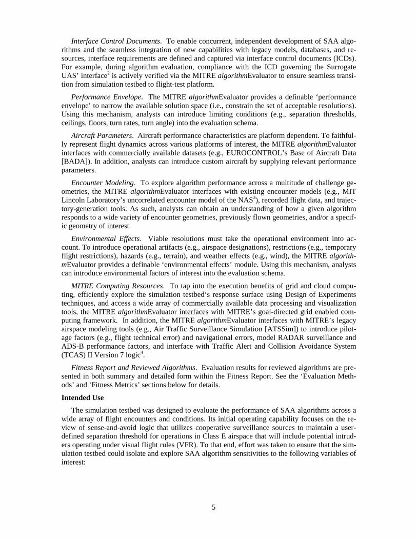
Interface Control Documents. To enable concurrent, independent development of SAA algo-rithms and the seamless integration of new capabilities with legacy models, databases, and re-sources, interface requirements are defined and captured via interface control documents (ICDs). For example, during algorithm evaluation, compliance with the ICD governing the Surrogate UAS’ interface2 is actively verified via the MITRE algorithmEvaluator to ensure seamless transi-tion from simulation testbed to flight-test platform.
Performance Envelope. The MITRE algorithmEvaluator provides a definable ‘performance envelope’ to narrow the available solution space (i.e., constrain the set of acceptable resolutions). Using this mechanism, analysts can introduce limiting conditions (e.g., separation thresholds, ceilings, floors, turn rates, turn angle) into the evaluation schema.
Aircraft Parameters. Aircraft performance characteristics are platform dependent. To faithful-ly represent flight dynamics across various platforms of interest, the MITRE algorithmEvaluator interfaces with commercially available datasets (e.g., EUROCONTROL’s Base of Aircraft Data [BADA]). In addition, analysts can introduce custom aircraft by supplying relevant performance parameters.
Encounter Modeling. To explore algorithm performance across a multitude of challenge ge-ometries, the MITRE algorithmEvaluator interfaces with existing encounter models (e.g., MIT Lincoln Laboratory’s uncorrelated encounter model of the NAS3), recorded flight data, and trajec-tory-generation tools. As such, analysts can obtain an understanding of how a given algorithm responds to a wide variety of encounter geometries, previously flown geometries, and/or a specif-ic geometry of interest.
Environmental Effects. Viable resolutions must take the operational environment into ac-count. To introduce operational artifacts (e.g., airspace designations), restrictions (e.g., temporary flight restrictions), hazards (e.g., terrain), and weather effects (e.g., wind), the MITRE algorith-mEvaluator provides a definable ‘environmental effects’ module. Using this mechanism, analysts can introduce environmental factors of interest into the evaluation schema.
MITRE Computing Resources. To tap into the execution benefits of grid and cloud compu-ting, efficiently explore the simulation testbed’s response surface using Design of Experiments techniques, and access a wide array of commercially available data processing and visualization tools, the MITRE algorithmEvaluator interfaces with MITRE’s goal-directed grid enabled com-puting framework. In addition, the MITRE algorithmEvaluator interfaces with MITRE’s legacy airspace modeling tools (e.g., Air Traffic Surveillance Simulation [ATSSim]) to introduce pilot-age factors (e.g., flight technical error) and navigational errors, model RADAR surveillance and ADS-B performance factors, and interface with Traffic Alert and Collision Avoidance System (TCAS) II Version 7 logic4.
Fitness Report and Reviewed Algorithms. Evaluation results for reviewed algorithms are pre-sented in both summary and detailed form within the Fitness Report. See the ‘Evaluation Meth-ods’ and ‘Fitness Metrics’ sections below for details.
Intended Use
The simulation testbed was designed to evaluate the performance of SAA algorithms across a wide array of flight encounters and conditions. Its initial operating capability focuses on the re-view of sense-and-avoid logic that utilizes cooperative surveillance sources to maintain a user-defined separation threshold for operations in Class E airspace that will include potential intrud-ers operating under visual flight rules (VFR). To that end, effort was taken to ensure that the sim-ulation testbed could isolate and explore SAA algorithm sensitivities to the following variables of interest:

6
• Sources of cooperative-surveillance information (e.g., ADS-B, Traffic Information Service Broadcast [TIS-B]);
• Quality of cooperative-surveillance information (e.g., Availability, Integrity, and Ac-curacy);
• Density and composition of proximate traffic;
• Performance envelope selections (e.g., separation-threshold setting);
• Environmental effects; and
• Own-ship selection.
Capability Description
The simulation testbed can be operated in either a portable or a network-enabled mode. In the portable mode, the MITRE algorithmEvaluator operates in a standalone configuration; using only the computing power of the computing device (e.g., laptop) on which it is resident. In this mode, an analyst can evaluate algorithms using both Monte Carlo and discrete event simulation tech-niques supported locally by the MITRE algorithmEvaluator. This particular mode is well suited to performing field examinations of minor-algorithm modifications when deployed to remote test locations.
In the network-enabled mode the simulation testbed leverages a middleware framework called the MITRE Elastic Goal-Directed Simulation Framework (i.e., MEG) to perform goal-directed, grid-based replication management across MITRE’s large computing clusters5. In this mode, the analyst defines variables of interests and uses MEG’s Design of Experiments services to efficient-ly explore the model’s response frontier. This particular mode is well suited for performing de-tailed sensitivity analyses quickly.
Evaluation Methods
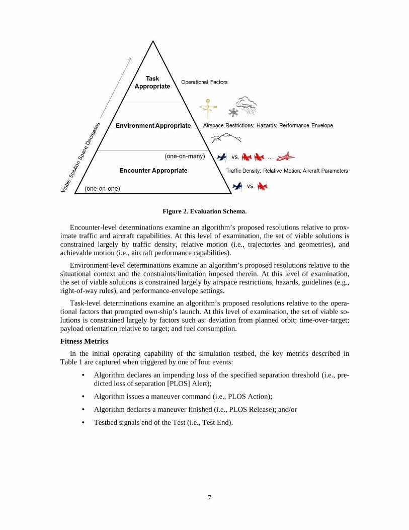
SAA algorithm performance is evaluated relative to three levels of appropriateness: encounter, environment, and task. As illustrated in Figure 2, each level of consideration builds upon the pri-or; effectively narrowing the viable solution space in the process. The initial operating capability of the simulation testbed is focused primarily on the encounter and environment levels; relative weightings (contained within the rating criteria) convey suitability/appropriateness conventions and can be used to explore tradeoffs both within and among the individual levels.
7
Figure 2. Evaluation Schema.
Encounter-level determinations examine an algorithm’s proposed resolutions relative to prox-imate traffic and aircraft capabilities. At this level of examination, the set of viable solutions is constrained largely by traffic density, relative motion (i.e., trajectories and geometries), and achievable motion (i.e., aircraft performance capabilities).
Environment-level determinations examine an algorithm’s proposed resolutions relative to the situational context and the constraints/limitation imposed therein. At this level of examination, the set of viable solutions is constrained largely by airspace restrictions, hazards, guidelines (e.g., right-of-way rules), and performance-envelope settings.
Task-level determinations examine an algorithm’s proposed resolutions relative to the opera-tional factors that prompted own-ship’s launch. At this level of examination, the set of viable so-lutions is constrained largely by factors such as: deviation from planned orbit; time-over-target; payload orientation relative to target; and fuel consumption.
Fitness Metrics
In the initial operating capability of the simulation testbed, the key metrics described in Table 1 are captured when triggered by one of four events:
• Algorithm declares an impending loss of the specified separation threshold (i.e., pre-dicted loss of separation [PLOS] Alert);
• Algorithm issues a maneuver command (i.e., PLOS Action);
• Algorithm declares a maneuver finished (i.e., PLOS Release); and/or
• Testbed signals end of the Test (i.e., Test End).

8
Table 1. Triggers & Metrics –“What is Measured When”.
Trigger(s) Metric Definition
PLOS Alert; PLOS Action
Distance to PLOS Distance to the point where the specified separation is lost
PLOS Alert; PLOS Action
Time to PLOS Time to the point where the specified separation is lost
PLOS Alert; PLOS Action
Predicted Miss Distance Forecast of the distance between own-ship and the intruder aircraft at closest point of approach
PLOS Alert; PLOS Action
Alignment Relative location to the Intruder Aircraft (e.g., right of, left of, head on, overtake)
PLOS Action Maneuver Type Description of the issued maneuver command (i.e., Heading Change, Altitude Change, Speed Change, ComboH/A, Com-boA/S, ComboH/A/S)
PLOS Release Maneuver Effect Net change in separation distance
PLOS Release Maneuver Strength Description of the maneuver command’s aggressiveness in terms of specified and allowable: turn angle, turn rate, speed change (acceleration/deceleration), and climb/descend rates.
PLOS Release Maneuver Delay Time between commanded action and executed action
Test End Resolution Matrix
Exploration of the encounter space:
Test End Violation Ratio
Compares Loss of Separation (LOS) occurrences with and without the Algorithm engaged:
(# LOS with Algorithm) / (# LOS without Algorithm)
Test End Violation Severity Indication of the depth and duration of the violation.
Test End Induced Violation Number of LOS occurrences instigated by the Algorithm
Test End Flight Path Deviation Maximum deviation from the nominal flight path.
Test End Nuisance Alert Errant declaration of an impending loss of the specified separa-tion threshold
Test End Minimum Miss Distance
(Intruder)
Minimum distance between own-ship and the intruder aircraft
Note: Minimum horizontal distance between own-ship and the intruder aircraft when not separated vertically. Minimum difference in altitude between own-ship and intruder aircraft when not separated horizontally.
Test End Minimum Miss Distance
(Ceiling) Minimum vertical distance between own-ship and the specified ceiling
Test End Minimum Miss Distance
(Floor) Minimum vertical distance between own-ship and the specified floor
Test End Minimum Miss Distance
(Hazard) Minimum distance between own-ship and other hazards (e.g., terrain, TRF, restricted airspace, manmade obstacle)
9
Using the above metrics, the Fitness Report summarizes an SAA algorithm’s performance against a given test case (i.e., a unique combination of flight encounter and conditions) and the set of all test cases to which it was subjected. In addition, using the before mentioned ratings criteria, the relative importance of one measurement over another—as conveyed by the analyst’s weighting selections— is taken into account to generate a single utility score for the algorithm.
FLIGHT-TEST PLATFORM AND TESTBED
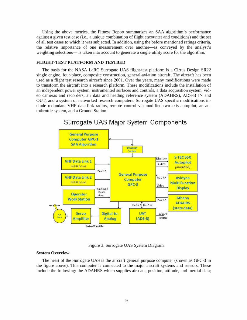
The basis for the NASA LaRC Surrogate UAS flight-test platform is a Cirrus Design SR22 single engine, four-place, composite construction, general-aviation aircraft. The aircraft has been used as a flight test research aircraft since 2001. Over the years, many modifications were made to transform the aircraft into a research platform. These modifications include the installation of an independent power system, instrumented surfaces and controls, a data acquisition system, vid-eo cameras and recorders, air data and heading reference system (ADAHRS), ADS-B IN and OUT, and a system of networked research computers. Surrogate UAS specific modifications in-clude redundant VHF data-link radios, remote control via modified two-axis autopilot, an au-tothrottle system, and a Ground Station.
Figure 3. Surrogate UAS System Diagram.
System Overview
The heart of the Surrogate UAS is the aircraft general purpose computer (shown as GPC-3 in the figure above). This computer is connected to the major aircraft systems and sensors. These include the following: the ADAHRS which supplies air data, position, attitude, and inertial data;

10
the S-TEC 55X (modified), which permits the GPC-3 to control the autopilot's modes, vertical speed settings, and provide steering inputs; the Avidyne EX5000 Multi-Function Display (MFD), which displays research-computer generated moving map information; an instrument panel switch, which enables the Avidyne MFD to display either normal navigation data or research vid-eo from the GPC-3; two full duplex Teledesign TS-4000 VHF radio modems for passing state, status, and command data (e.g., altitude, heading, vertical speed, airspeed) between the Surrogate UAS and the Ground Station; the Garmin GDL 90 UAT, which provides ADS-B, TIS-B, and other data; and the human-machine interface.
A second general purpose computer, GPC-1, is used to host the SAA algorithms and provide separate partitioning of the flight software. The main computer, GPC-3, has the job of interfacing to the aircraft systems and sensors, gathering data, and flying the aircraft through the autopilot and autothrottle. The second computer is intended only to host auxiliary software and does not interface directly to any of the aircraft systems other than the 10/100 Mbs network switch and the Operator Workstation. The data processed by GPC-1 is served to it by GPC-3 over the network. Processed results are passed back to GPC-3 over the network.
Intended Use
The Surrogate UAS System was created to serve as a research platform to aide in the investi-gation and testing of systems, sensors, and procedures that will make it possible to safely inte-grate unmanned aircraft into the non-segregated civil airspace. The Surrogate UAS System makes use of many research systems previously installed onboard the SR22 to enhance its role as a re-search platform. These previously installed systems include a separate research power system, the ADAHRS, video cameras, video recorders, instrumentation, and multiple research computers. It is envisioned that researchers from NASA, other government agencies, and academic institutions would use the Surrogate UAS to research and test UAS technology. The basic Surrogate UAS concept of operations (CONOPS) requires an experienced NASA Safety Pilot/Pilot in Command and Systems Operator on board for all research flights. This CONOPS makes it possible to “file and fly” almost anywhere in the NAS and interoperate with other air traffic under existing air traffic control (ATC) rules. This makes it possible to perform research and test systems in the NAS under real-world conditions with other traffic subject to normal ATC rules. Real UAS can-not be used in this way and must be operated in a manner that is either segregated from other manned aircraft in restricted airspace, or with operational restrictions under a Certificate of Waiv-er or Authorization (COA) or Special Airworthiness Certificate-Experimental Category (SAC-EC).
Capability Description
The Surrogate UAS is capable of remote control from the Ground Station, the onboard Sys-tems Operator, or automatically via onboard software. In all three modes, remote control is ac-complished via the issuance of four commands: altitude, vertical speed, heading, and airspeed. The remote control process begins when the aircraft is 500 feet or more above ground level (AGL) as specified by safety procedures. The aircraft must be above 500 feet before the modified autopilot circuit breaker may be engaged. When the Ground Station is in control of the aircraft, the range of operation can extend from 35 to 40 nautical miles from the Ground Station. The UAS software can command heading changes by sending GPS Steering (GPSS) signals to the autopi-lot. This results in bank angle commands of up to ±25 degrees. The autopilot may further limit this external command according to internal control laws based on the aircraft ground speed to maintain turns to 90% of standard rate. In most cases, the actual bank angle command is 17 to 20 degrees for a significant heading change.
11
To engage the Surrogate UAS mode and control the aircraft, a series of actions are required by both the Safety Pilot/Pilot in Command and the Systems Operator. The sequence begins with en-abling power to the modified S-TEC Autopilot at a predetermined altitude above 500 feet AGL. When the aircraft is in level flight and stable at a pre-briefed altitude and speed, the Safety Pi-lot/Pilot in Command activates a switch that switches the autopilot steering signal source from the Garmin GNS 430 navigation unit to the GPC-3 research computer. A second switch is activated to engage the clutch in the autothrottle drive servo. At this point, the Systems Operator may set a boolean in the software that enables computer control of the S-TEC autopilot and the autothrottle. In this configuration, the Ground Station is able to send commands (i.e., altitude, vertical speed, heading, and airspeed) to the aircraft for transfer to the autopilot and autothrottle. If the plan is for the Systems Operator to control the aircraft, a second boolean must be set to disable Ground Sta-tion control and enable the Systems Operator to send commands. In the autonomous mode, soft-ware running in a separate computer (GPC-1) is enabled and allowed to pass UAS Commands over the network to GPC-3 for translation into autonomous aircraft maneuvers. For the SAA flight tests, the autonomous mode is used.
Safety Features
Many safety features are designed into the Surrogate UAS System. The main safety feature centers on the use of the autopilot to provide Surrogate UAS control of the aircraft. The autopilot is a limited authority device that can be overridden, disengaged or disabled by the Safety Pi-lot/Pilot in Command. The Surrogate UAS System is indirectly flying the aircraft by sending commands to the limited authority autopilot. The autopilot can be disengaged by pressing the au-topilot disengage button on either the Pilot's or Co-Pilot's side arm controller. The autopilot dis-engage signal is also read by the Surrogate UAS software and is programmed to terminate any command or control signals to the autopilot or autothrottle. The Systems Operator can also disa-ble all autopilot and autothrottle command and control signals by resetting the Enable Remote Control Boolean in the software. By design, the Safety Pilot/Pilot in Command can also disable the autopilot by pulling the autopilot circuit breaker without looking for it (i.e., a collar was placed over the autopilot circuit breaker to enable the Safety Pilot/Pilot in Command to feel and pull it without seeing it).
The autothrottle can be overridden by applying more force than the 11.7 ft-lbs (41.3 in-lbs) set in the drive servo clutch. The autothrottle can also be disabled by the deactivating the Clutch En-able Switch that is conveniently located on the center console. An additional safety feature is a quick-disconnect on each end of the autothrottle drive shaft. Cotter pins on each end of the shaft allow for quick and easy removal of the throttle drive shaft. This action will completely disable the autothrottle and return the throttle to its normal unmodified condition.
The separate and independent research power system is an additional safety feature. This al-lows the Safety Pilot/Pilot in Command or the Systems Operator to disable all research power with one centrally located Research Power Switch on the center console. This action will remove power from all research systems and stop all inputs to the autopilot and autothrottle. The combi-nation of an experienced Safety Pilot/Pilot in Command and a Systems Operator is also one of the Surrogate UAS safety features. The Systems Operator is responsible for the operation and control of all the research systems hardware and software. This division of responsibilities makes it pos-sible for the Safety Pilot/Pilot in Command to concentrate solely on traditional pilot duties.
Research Systems
Several research systems were installed specifically for the Surrogate UAS mode of opera-tions. These systems include the two Teledesign TS-4000 VHF radio modems. These radios op-

12
erate as redundant full duplex message conduits between the aircraft and Ground Station, and they operate on two authorized frequencies in the 150-174 MHz VHF band. Customized half-wave dipole antennas were built in-house for the radios. Both antennas are tuned to their respec-tive operating frequencies for maximum efficiency.
The autothrottle is also an in-house design and customized for the aircraft. The autothrottle drive servo is a standard Cobham S-TEC model 108 pitch servo. The digital to analog converter is also a standard off the shelf component. The autothrottle servo amplifier, mounting structure, and drive shaft were designed and built in house. The autothrottle can be completely removed from the aircraft when it is desired to restore the aircraft to the non-research mode. The Surrogate UAS autopilot is a modified Cobham S-TEC 55X two-axis model that is common and found in many general aviation aircraft. Modifications were made inside the autopilot and wiring was add-ed and brought outside the unit on unused rear connector interface pins. The additional wiring is connected to GPC-3 to enable mode and vertical speed control. Lateral steering is accomplished by inputting ARINC 429 steering and ground speed signals from GPC-3 in place of the Garmin GNS 430 navigation unit. With the ability to control the autopilot mode, vertical axis, and the lateral axis, 3-D flight is possible from the research computer. A Condor CEI-520 PCI card in GPC-3 has both ARINC 429 and discrete input/output capability to control the autopilot.
Human Machine Interface
The Surrogate UAS human machine interface is accomplished through the use of switches, knobs, a keyboard, a mouse, computer generated video screens, and the software graphical user interface (GUI). The mouse is a custom designed three button arrangement that is built into the right rear seat armrest for use by the Systems Operator. When the Surrogate UAS software is running, a series of GUI menus may be activated to control all aspects of the software in the air-craft and in the Ground Station. A system of GUI’s are used by the System Operator to enable or disable certain software functions, change control law gains, change filter parameters and enter the four UAS commands. When entering a command, the System Operator has the option of en-tering the command from the keyboard or using the left mouse button to click a GUI + or – sym-bol to advance or retard the existing value. When commands are sent from the Ground Station and received in the aircraft, they are echoed back to the Ground Station for display on the moving map display. This confirms to the Ground Station Operator that the commands were received in the aircraft. The aircraft moving map display also displays the commands. Voice radio communi-cations is also used between the Safety Pilot/Pilot in Command and the Ground Station to verify operations.
INTEGRATED TEST CONCEPT
MITRE and NASA LaRC collaborated to develop an integrated capability for testing proto-type SAA system elements with an initial emphasis on ADS-B based algorithmic alternatives for self separation (see Figure 4). Algorithms (developed in-house or developed by other research organizations) are first evaluated on the MITRE computer simulation testbed. If performance is satisfactory, the same algorithms can then be evaluated in flight onboard the NASA LaRC Surro-gate UAS testbed. The resulting performance data informs incremental-design efforts, and the integrated test concept accelerates the maturation process.
13
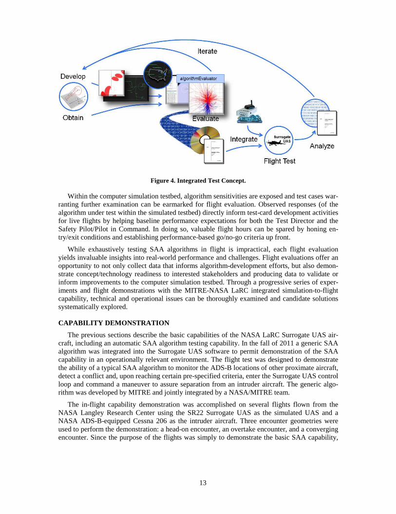
Figure 4. Integrated Test Concept.
Within the computer simulation testbed, algorithm sensitivities are exposed and test cases war-ranting further examination can be earmarked for flight evaluation. Observed responses (of the algorithm under test within the simulated testbed) directly inform test-card development activities for live flights by helping baseline performance expectations for both the Test Director and the Safety Pilot/Pilot in Command. In doing so, valuable flight hours can be spared by honing en-try/exit conditions and establishing performance-based go/no-go criteria up front.
While exhaustively testing SAA algorithms in flight is impractical, each flight evaluation yields invaluable insights into real-world performance and challenges. Flight evaluations offer an opportunity to not only collect data that informs algorithm-development efforts, but also demon-strate concept/technology readiness to interested stakeholders and producing data to validate or inform improvements to the computer simulation testbed. Through a progressive series of exper-iments and flight demonstrations with the MITRE-NASA LaRC integrated simulation-to-flight capability, technical and operational issues can be thoroughly examined and candidate solutions systematically explored.
CAPABILITY DEMONSTRATION
The previous sections describe the basic capabilities of the NASA LaRC Surrogate UAS air-craft, including an automatic SAA algorithm testing capability. In the fall of 2011 a generic SAA algorithm was integrated into the Surrogate UAS software to permit demonstration of the SAA capability in an operationally relevant environment. The flight test was designed to demonstrate the ability of a typical SAA algorithm to monitor the ADS-B locations of other proximate aircraft, detect a conflict and, upon reaching certain pre-specified criteria, enter the Surrogate UAS control loop and command a maneuver to assure separation from an intruder aircraft. The generic algo-rithm was developed by MITRE and jointly integrated by a NASA/MITRE team.
The in-flight capability demonstration was accomplished on several flights flown from the NASA Langley Research Center using the SR22 Surrogate UAS as the simulated UAS and a NASA ADS-B-equipped Cessna 206 as the intruder aircraft. Three encounter geometries were used to perform the demonstration: a head-on encounter, an overtake encounter, and a converging encounter. Since the purpose of the flights was simply to demonstrate the basic SAA capability,
14
an exhaustive set of geometries was not considered necessary. The demonstration was flown in daylight/VMC conditions so that non-participating aircraft could be seen and avoided by the two Safety Pilot/Pilot in Commands in accordance with 14 CFR Part 91.111/113. The encounters were set up by the participating pilots using a combination of electronic navigation signals, ground references, and coordinated timed turns. All encounters required the SR22 Safety Pi-lot/Pilot in Command to have visual contact with the C206 intruder aircraft for the encounter to proceed inside of the pilot’s estimate of 3 nmi or 1 minute to the closest point of approach (CPA), whichever was lower.
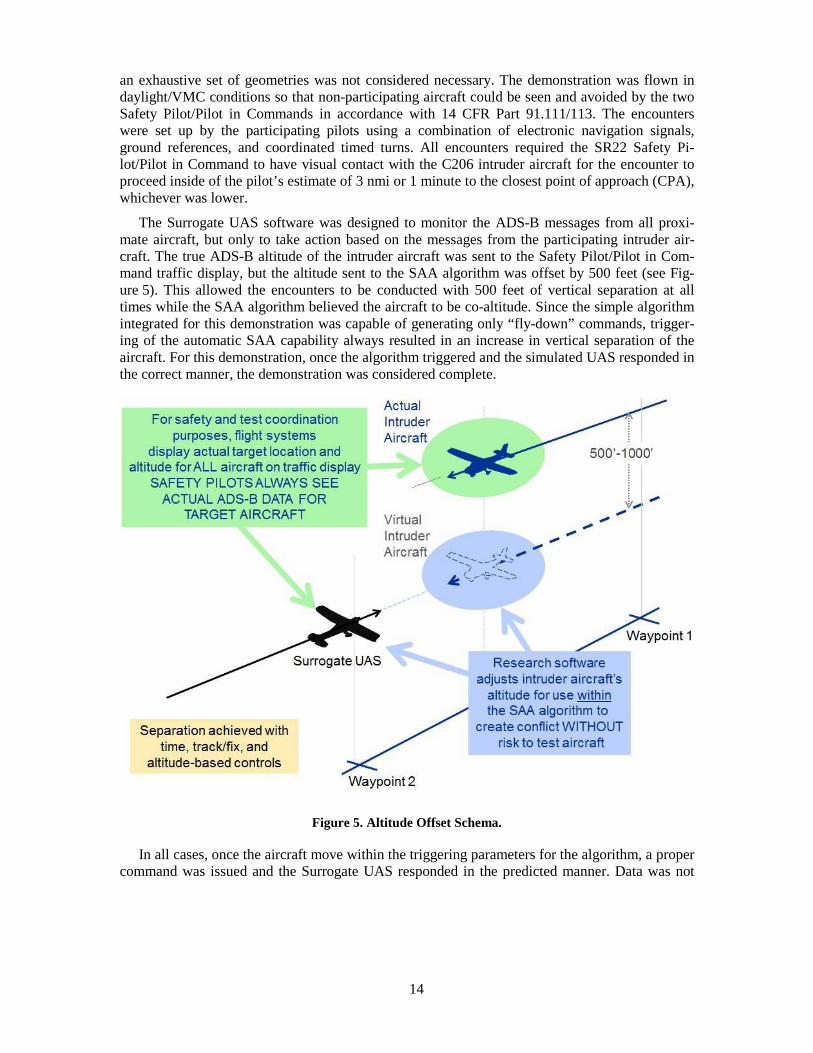
The Surrogate UAS software was designed to monitor the ADS-B messages from all proxi-mate aircraft, but only to take action based on the messages from the participating intruder air-craft. The true ADS-B altitude of the intruder aircraft was sent to the Safety Pilot/Pilot in Com-mand traffic display, but the altitude sent to the SAA algorithm was offset by 500 feet (see Fig-ure 5). This allowed the encounters to be conducted with 500 feet of vertical separation at all times while the SAA algorithm believed the aircraft to be co-altitude. Since the simple algorithm integrated for this demonstration was capable of generating only “fly-down” commands, trigger-ing of the automatic SAA capability always resulted in an increase in vertical separation of the aircraft. For this demonstration, once the algorithm triggered and the simulated UAS responded in the correct manner, the demonstration was considered complete.
Figure 5. Altitude Offset Schema.
In all cases, once the aircraft move within the triggering parameters for the algorithm, a proper command was issued and the Surrogate UAS responded in the predicted manner. Data was not
15
collected on algorithm performance or generated miss distances since the purpose of the flights was only to demonstrate a capability, not to conduct algorithm research.
The flights were witnessed by technical and management personnel from both NASA LaRC and MITRE as this proof-of-capability was necessary to allow progression to the next phase of testing in which algorithm research would be conducted. The algorithm research phase is current-ly underway and is briefly described in the next section.
FUTURE STUDIES
Flight evaluations of candidate SAA algorithms are planned for September 2012 using the NASA LaRC Surrogate UAS testbed. The flight evaluations will occur in eastern North Dakota over a 2-week period in partnership with the University of North Dakota. These flights will help validate the results of extensive modeling and simulation studies conducted by MITRE and other algorithm development research organizations. In addition, as the MITRE-NASA LaRC research team uses the integrated capability to explore the viability of cooperative automatic SAA in an operationally relevant environment, the September 2012 efforts will serve as an end-to-end demonstration of the integrated test concept.
Since the October 2011 demonstration, a more sophisticated version of the Surrogate UAS SAA capability has been developed. This expanded capability allows the integration and testing of multiple SAA algorithms in flight and also allows the integration of targets derived from vari-ous ground-based sensors with ADS-B and TIS-B targets. This enhanced capability is currently being tested at NASA LaRC with cooperation from the other project partners, and it will serve a key role in the flight evaluations scheduled for September 2012 in eastern North Dakota.
While the immediate future use of the integrated simulation-to-flight SAA capability is target-ed at cooperative automatic SAA, this effort represents only one of several possible approaches to solving UAS SAA challenges. The authors hope that the basic capability demonstrated last Octo-ber at NASA LaRC and the September 2012 campaign in eastern North Dakota will lead to op-portunities for further expansion of the simulation-to-flight capability and the testing of other SAA approaches.
SUMMARY
The NASA-MITRE team has developed an integrated simulation and flight test capability for testing prototype sense-and-avoid system elements with an initial emphasis on ADS-B based al-gorithmic alternatives for self separation. This integrated system includes the capability to devel-op algorithms, perform fast-time simulation testing, generate fitness reports, integrate into the flight software framework, and execute flight tests in real-world conditions. The algorithm devel-opment and fast-time simulation testing capabilities were developed by MITRE. The software framework for hosting multiple SAA algorithms, and the flight testing capabilities of the Surro-gate UAS aircraft were developed by the NASA LaRC Research Center. These separately devel-oped capabilities were brought together and have resulted in a successful SAA flight test in Octo-ber 2011. The value of this integrated process was fully demonstrated and will be expanded to accommodate multiple SAA algorithms in the flight evaluations scheduled for September 2012 in eastern North Dakota. This process can serve as a model for the development of systems and al-gorithms needed to enable the safe integration of UAS in the NAS.
ACKNOWLEDGEMENTS
The NASA and MITRE contributions to this work were supported through NASA LaRC and MITRE Sponsored Research program funds. The views, opinions, and/or findings contained in

16
this presentation are those of author(s) should not be construed as an official Government posi-tion, policy, or decision, unless designated by other documentation. The authors wish to thank Frank Jones, Glenn Roberts, and Andy Lacher for their vision, enthusiastic support, and valuable feedback. The authors also wish to acknowledge the invaluable contributions of Cathy Buttrill, Deihim Hashemi, Jonathan Schwartz, Ganghaui Wang, Rick Yasky, Artie Jessup, Lee Joyce, Lu-ci Crittenden, Cecil Mellanson, and Pierre Chaloux in establishing the integrated simulation-to-flight capability.
REFERENCES 114 CFR §92.225 and §91.227 2C. Buttrill, "Cirrus SR-22 Surrogate UAS Interface Control Document", Version 3.0, 2/29/2012. 3M. J. Kochenderfer et al., "Uncorrelated Encounter Model of the National Airspace System", Version 1.0, 11/14/2008. 4A. Burns et al., "Traffic Alert and Collision Avoidance System Simulation Software Design Document", Version 7, MITRE Technical Report (MTR93W0000178R02), June 1997. 5E. H. Page et al., “Goal-Directed Grid Enabled Computing for Legacy Simulations," in Proceedings for the Modeling and Simulation on Grid and Cloud Computing (MSGC2012) Workshop, Ottawa, Canada, 2012.
©2012 The MITRE Corporation all rights reserved.