firestarter – a real-time fire simulatorpages.cs.wisc.edu/~dekruijf/docs/capstone.pdfcomp489...
TRANSCRIPT
firestarter – A Real-Time Fire Simulator Marc de Kruijf
Computer Science Capstone
Supervisor: Professor Susan Fox
Second Reader: Professor Michael Schneider
Abstract
Many obstacles exist in attempting to graphically render physical
phenomena that are highly fluid and ostensibly chaotic in nature. Fire is a
prime example of such phenomena. Given the unrealizable computational
complexity of chemical-atomic modeling, this paper explores how to best
apply our current understanding of the physical fire model to balance
computational stresses for optimal realism. Special emphasis is given
specifically to the constraints imposed by real-time rendering, as opposed to
production pipeline rendering, introducing firestarter – a real-time fire
simulator developed by the author using OpenGL – which features some
unique implementations of previously discussed topics.
COMP489 firestarter – A Real-Time Fire Simulator 1
1 Introduction
Combustion is a complex process. The combustion of a candle flame has the following
oxidation equation [8]:
C17H35COOH + 11O2 → 9H2O + 5CO2 + 5CO + 8C + 9H2
This equation should give just about the right impression: we could never hope to
compute a truly accurate fire simulation within any reasonable time frame, even if we did
know all there was to know about fire (which we do not). Therefore, as the reader may be
relieved to hear, this paper does not present complex analyses of physical and chemical
equations. Rather, it discusses the rendering of these scientific phenomena from a purely
computational perspective – how can we best represent them given the tools available to
computer graphics developers? firestarter is a real-time fire simulator developed by the
author using OpenGL that attempts to provide an answer to this question.
I will begin in section 2 by highlighting important aspects of some selected
literature in 3D graphical fire rendering, with particular emphasis on those articles and
papers influential in the creation of firestarter. Methods for both pipelined (e.g. film
production) and real-time (e.g. interactive applications) visualization are explored.
Section 3 discusses important physical properties of fire that need to be considered in
designing a simulation, and section 4 expands by analyzing those properties and
evaluating them in the context of real-time computation. In section 5, firestarter is
presented and discussed at length, including a discussion of time complexity and other
implementation specific issues and solutions. Finally, section 6 concludes with a
discussion of some observations made during the design process, and recommends areas
for future development.
2 Published Work in 3D Fire
2.1 The premiere ; the particle system
Consider a waterfall. It’s a beautiful sunny spring day, and birds can be heard chirping
merrily in the forks of the trees. You hear the rustling of leaves in the cool breeze, and
water rushing over the waterfall’s edge and pounding down onto the rocks below….
Now back up: once again envision that water running over the edge of the cliff.
Imagine the water separating as it falls, parting into many individual, tiny droplets. Each
of these droplets has its own position in space, its own velocity vector, its own size, its
own mineral content, its own temperature, etc.. To view the water falling in this manner
is to view the waterfall as if it were a particle system.
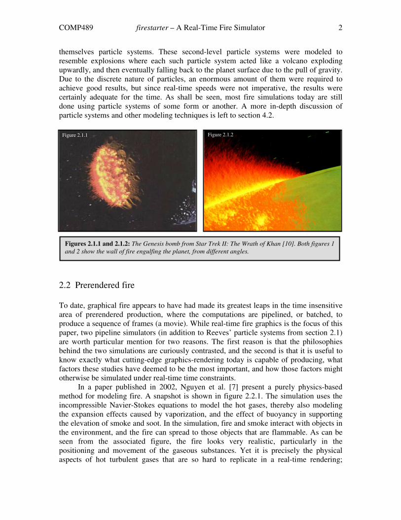
With the very first computerized graphical fire simulation, Reeves [10] introduced
particle systems as a modeling, animating and rendering primitive back in 1983. In the
film Star Trek II: The Wrath of Khan, his so-called “expanding wall-of-fire” was
generated using a two-level hierarchy of particle systems. The top-level system was
centered at the impact point of a genesis bomb, generating particles which were
COMP489 firestarter – A Real-Time Fire Simulator 2
themselves particle systems. These second-level particle systems were modeled to
resemble explosions where each such particle system acted like a volcano exploding
upwardly, and then eventually falling back to the planet surface due to the pull of gravity.
Due to the discrete nature of particles, an enormous amount of them were required to
achieve good results, but since real-time speeds were not imperative, the results were
certainly adequate for the time. As shall be seen, most fire simulations today are still
done using particle systems of some form or another. A more in-depth discussion of
particle systems and other modeling techniques is left to section 4.2.
2.2 Prerendered fire
To date, graphical fire appears to have had made its greatest leaps in the time insensitive
area of prerendered production, where the computations are pipelined, or batched, to
produce a sequence of frames (a movie). While real-time fire graphics is the focus of this
paper, two pipeline simulators (in addition to Reeves’ particle systems from section 2.1)
are worth particular mention for two reasons. The first reason is that the philosophies
behind the two simulations are curiously contrasted, and the second is that it is useful to
know exactly what cutting-edge graphics-rendering today is capable of producing, what
factors these studies have deemed to be the most important, and how those factors might
otherwise be simulated under real-time time constraints.
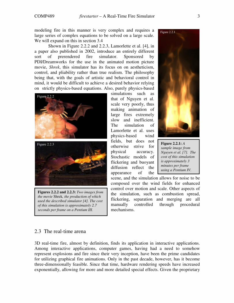
In a paper published in 2002, Nguyen et al. [7] present a purely physics-based
method for modeling fire. A snapshot is shown in figure 2.2.1. The simulation uses the
incompressible Navier-Stokes equations to model the hot gases, thereby also modeling
the expansion effects caused by vaporization, and the effect of buoyancy in supporting
the elevation of smoke and soot. In the simulation, fire and smoke interact with objects in
the environment, and the fire can spread to those objects that are flammable. As can be
seen from the associated figure, the fire looks very realistic, particularly in the
positioning and movement of the gaseous substances. Yet it is precisely the physical
aspects of hot turbulent gases that are so hard to replicate in a real-time rendering;
Figures 2.1.1 and 2.1.2: The Genesis bomb from Star Trek II: The Wrath of Khan [10]. Both figures 1
and 2 show the wall of fire engulfing the planet, from different angles.
Figure 2.1.2 Figure 2.1.1
COMP489 firestarter – A Real-Time Fire Simulator 3
modeling fire in this manner is very complex and requires a
large series of complex equations to be solved on a large scale.
We will expand on this in section 3.4
Shown in Figure 2.2.2 and 2.2.3, Lamorlette et al. [4], in
a paper also published in 2002, introduce an entirely different
sort of prerendered fire simulator. Sponsored by
PDI/Dreamworks for the use in the animated motion picture
movie, Shrek, this simulator has its focus on on aestheticism,
control, and pliability rather than true realism. The philosophy
being that, with the goals of artistic and behavioral control in
mind, it would be difficult to achieve a desired behavior relying
on strictly physics-based equations. Also, purely physics-based
simulations such as
that of Nguyen et al.
scale very poorly, thus
making animation of
large fires extremely
slow and inefficient.
The simulation of
Lamorlette et al. uses
physics-based wind
fields, but does not
otherwise strive for
physical accuracy.
Stochastic models of
flickering and buoyant
diffusion reflect the
appearance of the
scene, and the simulation allows for noise to be
composed over the wind fields for enhanced
control over motion and scale. Other aspects of
the simulation, such as combustion spread,
flickering, separation and merging are all
manually controlled through procedural
mechanisms.
2.3 The real-time arena
3D real-time fire, almost by definition, finds its application in interactive applications.
Among interactive applications, computer games, having had a need to somehow
represent explosions and fire since their very inception, have been the prime candidates
for utilizing graphical fire animations. Only in the past decade, however, has it become
three-dimensionally feasible. Since that time, hardware rendering speeds have increased
exponentially, allowing for more and more detailed special effects. Given the proprietary
Figure 2.2.1: A
sample image from
Nguyen et al. [7]. The
cost of this simulation
is approximately 3
minutes per frame
using a Pentium IV.
Figure 2.2.1
Figures 2.2.2 and 2.2.3: Two images from
the movie Shrek, the production of which
used the described simulator [4]. The cost
of this simulation is approximately 2.7
seconds per frame on a Pentium III.
Figure 2.2.2
Figure 2.2.3
COMP489 firestarter – A Real-Time Fire Simulator 4
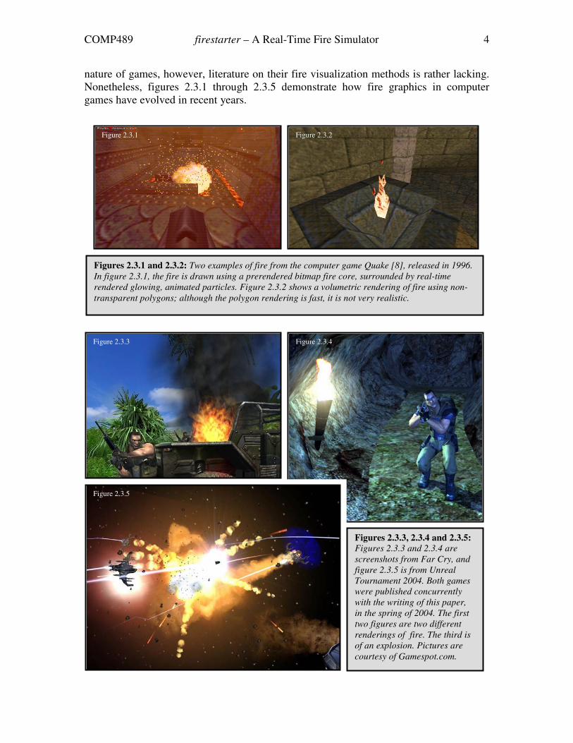
nature of games, however, literature on their fire visualization methods is rather lacking.
Nonetheless, figures 2.3.1 through 2.3.5 demonstrate how fire graphics in computer
games have evolved in recent years.
Figure 2.3.3 Figure 2.3.4
Figure 2.3.5
Figures 2.3.3, 2.3.4 and 2.3.5:
Figures 2.3.3 and 2.3.4 are
screenshots from Far Cry, and
figure 2.3.5 is from Unreal
Tournament 2004. Both games
were published concurrently
with the writing of this paper,
in the spring of 2004. The first
two figures are two different
renderings of fire. The third is
of an explosion. Pictures are
courtesy of Gamespot.com.
Figure 2.3.1 Figure 2.3.2
Figures 2.3.1 and 2.3.2: Two examples of fire from the computer game Quake [8], released in 1996.
In figure 2.3.1, the fire is drawn using a prerendered bitmap fire core, surrounded by real-time
rendered glowing, animated particles. Figure 2.3.2 shows a volumetric rendering of fire using non-
transparent polygons; although the polygon rendering is fast, it is not very realistic.
COMP489 firestarter – A Real-Time Fire Simulator 5
As an aside, combustion processes can loosely be
classified into two separate types of phenomena: deflagrations
(see figure 2.3.4) and detonations (see figure 2.3.5). In both of
these processes, chemical reactions convert fuel into hot
gaseous products. However, detonations are high speed events
where shock waves and other compressible effects are
important, whereas deflagrations are low speed events such as
everyday hearth or torch fires. Detonations are distinct enough
from regular fire that they are not explicitly considered in the
rest of this paper. Nor has any attempt been made to simulate
them in firestarter.
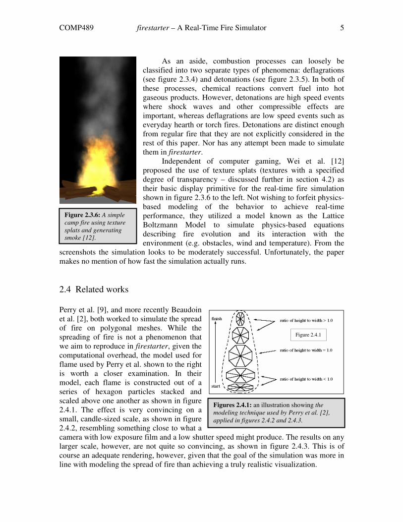
Independent of computer gaming, Wei et al. [12]
proposed the use of texture splats (textures with a specified
degree of transparency – discussed further in section 4.2) as
their basic display primitive for the real-time fire simulation
shown in figure 2.3.6 to the left. Not wishing to forfeit physics-
based modeling of the behavior to achieve real-time
performance, they utilized a model known as the Lattice
Boltzmann Model to simulate physics-based equations
describing fire evolution and its interaction with the
environment (e.g. obstacles, wind and temperature). From the
screenshots the simulation looks to be moderately successful. Unfortunately, the paper
makes no mention of how fast the simulation actually runs.
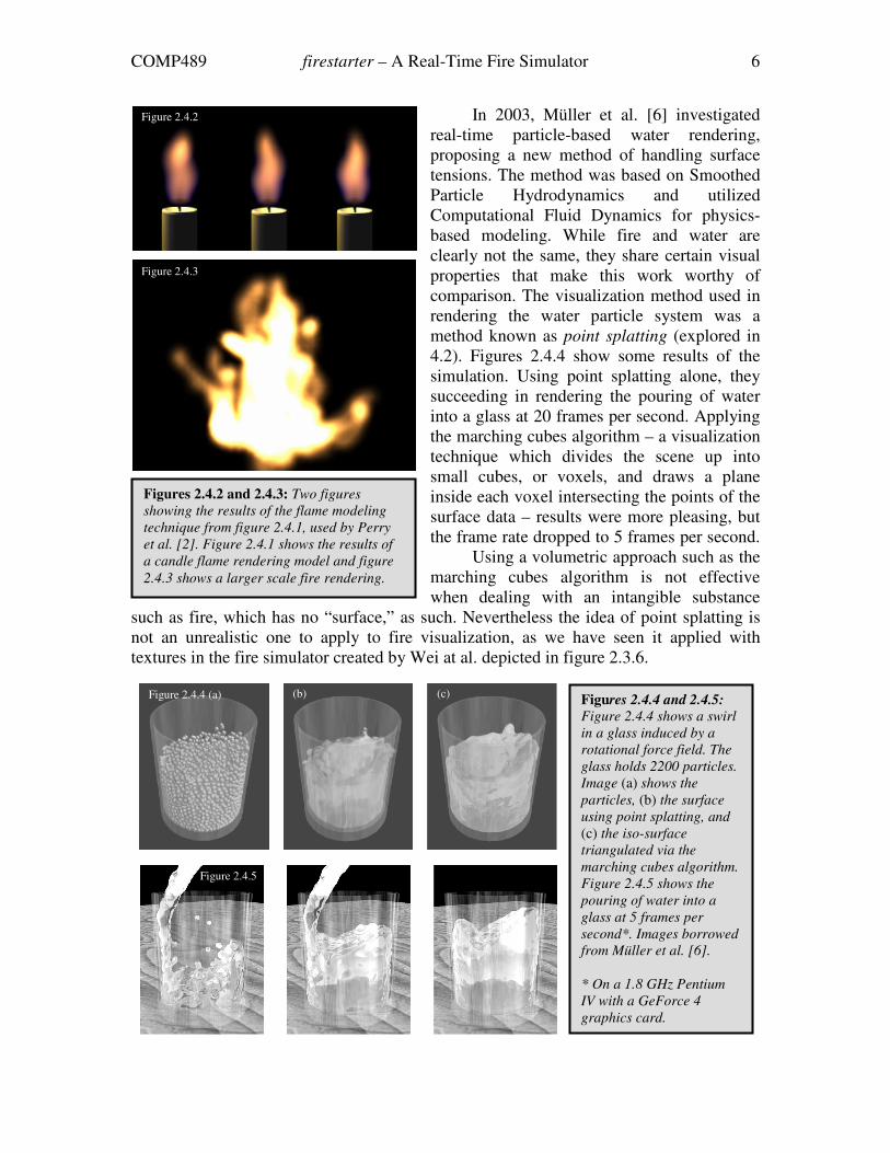
2.4 Related works
Perry et al. [9], and more recently Beaudoin
et al. [2], both worked to simulate the spread
of fire on polygonal meshes. While the
spreading of fire is not a phenomenon that
we aim to reproduce in firestarter, given the
computational overhead, the model used for
flame used by Perry et al. shown to the right
is worth a closer examination. In their
model, each flame is constructed out of a
series of hexagon particles stacked and
scaled above one another as shown in figure
2.4.1. The effect is very convincing on a
small, candle-sized scale, as shown in figure
2.4.2, resembling something close to what a
camera with low exposure film and a low shutter speed might produce. The results on any
larger scale, however, are not quite so convincing, as shown in figure 2.4.3. This is of
course an adequate rendering, however, given that the goal of the simulation was more in
line with modeling the spread of fire than achieving a truly realistic visualization.
Figure 2.3.6: A simple
camp fire using texture
splats and generating
smoke [12].
Figure 2.4.1
Figures 2.4.1: an illustration showing the
modeling technique used by Perry et al. [2],
applied in figures 2.4.2 and 2.4.3.
COMP489 firestarter – A Real-Time Fire Simulator 6
In 2003, Müller et al. [6] investigated
real-time particle-based water rendering,
proposing a new method of handling surface
tensions. The method was based on Smoothed
Particle Hydrodynamics and utilized
Computational Fluid Dynamics for physics-
based modeling. While fire and water are
clearly not the same, they share certain visual
properties that make this work worthy of
comparison. The visualization method used in
rendering the water particle system was a
method known as point splatting (explored in
4.2). Figures 2.4.4 show some results of the
simulation. Using point splatting alone, they
succeeding in rendering the pouring of water
into a glass at 20 frames per second. Applying
the marching cubes algorithm – a visualization
technique which divides the scene up into
small cubes, or voxels, and draws a plane
inside each voxel intersecting the points of the
surface data – results were more pleasing, but
the frame rate dropped to 5 frames per second.
Using a volumetric approach such as the
marching cubes algorithm is not effective
when dealing with an intangible substance
such as fire, which has no “surface,” as such. Nevertheless the idea of point splatting is
not an unrealistic one to apply to fire visualization, as we have seen it applied with
textures in the fire simulator created by Wei at al. depicted in figure 2.3.6.
Figures 2.4.2 and 2.4.3: Two figures
showing the results of the flame modeling
technique from figure 2.4.1, used by Perry
et al. [2]. Figure 2.4.1 shows the results of
a candle flame rendering model and figure
2.4.3 shows a larger scale fire rendering.
Figure 2.4.2
Figure 2.4.3
Figures 2.4.4 and 2.4.5:
Figure 2.4.4 shows a swirl
in a glass induced by a
rotational force field. The
glass holds 2200 particles.
Image (a) shows the
particles, (b) the surface
using point splatting, and
(c) the iso-surface
triangulated via the
marching cubes algorithm.
Figure 2.4.5 shows the
pouring of water into a
glass at 5 frames per
second*. Images borrowed
from Müller et al. [6].
* On a 1.8 GHz Pentium
IV with a GeForce 4
graphics card.
Figure 2.4.4 (a) (b) (c)
Figure 2.4.5
COMP489 firestarter – A Real-Time Fire Simulator 7
3 Fire: the Physical Model
3.1 The house is burning! Or is it…?
Common perception of an object on fire is that the object itself is burning. It is, however,
not the object that burns, but the fuel that the object emits into the surrounding
environment that burns. This fuel rises to the surface of the object through heat,
vaporizes, and then reacts with oxygen to ignite. Hence, fire requires the co-presence of
three elements: fuel, heat and oxygen [11].
� Fuel. Fuel can be in the form of a solid, liquid or gaseous substance, although all
fuels must be chemically decomposed into gases or vapors if they are to burn.
This decomposition process takes place through the action of heat.
� Heat. Heat is a measure of the molecular activity occurring within an object, with
higher the temperatures causing faster action in the molecules. If sufficient heat is
applied to an object, the molecules may move so fast that they break away from
the surface. This is how the fuel is transformed to gas.
� Oxygen. Oxygen is the oxidizing agent and is thus essential to combustion. At a
certain stage, fire particles may change to smoke particles because of lack of
oxygen in the air, which causes incomplete oxidization.
3.2 How to set a house on fire
The US Army Corps of Engineers [11] defines fire or combustion as “rapid oxidation
with the action (evolution) of heat and light.” Fire is subsequently described as being
produced through the following stages:
1. Oxidation causes the combustible material to decompose, slowly giving off gases,
including water vapor. It takes place continuously as long as it is exposed to an
oxidizing agent, which may be air. At ambient temperatures, oxidation is usually
so slow that the process is not noticeable to human senses. The combustible gases
are not yet ignitable during this early stage.
2. The rate of oxidation increases as the temperature rises, with some of the gas
eventually becoming ignitable. The point at which sufficient vapor is released to
cause a flammable mixture in the air is known as the flash point.
3. At the aforementioned flash point, the evolved gases are too rich in carbon
dioxide and water vapor to sustain flame very long. However, the heat of the
flame will start a secondary decomposition reaction process, eventually allowing
combustion to take place. This point is known as the fire point and is usually a
few degrees above the flash point.

COMP489 firestarter – A Real-Time Fire Simulator 8
4. Oxidation may be so fast that it blankets the fuel surface and excludes air,
preventing the char from burning and retarding the penetration of heat. This
delays the ignition temperatures in penetrating deeper into the combustible
material. However, as temperatures increase, the char begins to glow, air flows in
to support combustion, and the fuel itself burns as well as its decomposition
gases.
5. If more heat is generated than is lost through conduction, convection, or radiation,
the flame will persist and fire will come into being. Combustion will be sustained
until either heat, fuel, or the oxidizing agent are removed from the system.
3.3 Fire has genres
According to Nielsen [8], fire can loosely be divided into the following five visually
characteristic groups:
� Calm fire. A typical calm fire is the one illuminating your typical candlelit dinner
for two, and is thus the fiery analogue of the music industry’s ambient genre. A
calm fire is largely undisturbed by internal or external force alterations. Hence,
the flame is perceived as calm, and appears to barely move, if at all.
� Freely fed. A freely fed fire is a fire that has no lack of fuel and receives plenty of
oxygen, although both will fluctuate somewhat with time and position. This is in
contrast to a calm fire, which has a more or less constant and regulated amount of
both fuel and oxygen available for consumption at all times and in all regions of
the fire.
� Violent fire. In a violent fire, external forces act strongly on the fire, resulting in
an irregular fuel feed and the spread of fuel components in directions other than
mostly vertically. Violent fires are temperamental and highly unpredictable due to
the underlying complexity of the system and the number of contributing forces.
� Pressure fed. A pressure fed fire is a freely fed fire which has velocity vectors
imposed on the fuel as it is released into the air.
� Explosions. In an explosion, the fuel is initially compressed. Ignition results in
shockwaves, which induce new small explosions, resulting in further shock
waves. Explosions were earlier referred to in this paper as detonations.
firestarter mostly resembles the freely fed fire, in that the fuel amount will be
approximately constant, but not entirely so, and the amount of oxygen is somewhat
stochastic, with a dearth of oxygen in the heart of the system where the flame is the
hottest and the most oxygen is consumed. This type of fire is the most common type of
COMP489 firestarter – A Real-Time Fire Simulator 9
fire, being the one that would most likely result from, to give a random example, lighting
a house on fire.
3.4 Why fire looks the way it looks
Fire is a complex phenomenon, to say the least. For the purposes of this paper, it is
necessary to provide an overview of only the most important physical traits affecting how
we, as humans, visually perceive fire, without delving into mathematical specifics and
introducing cumbersome equations. Some issues are the fire color spectrum, air friction
causing drag, and the formation and appearance of soot and smoke.
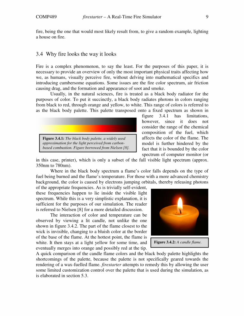
Usually, in the natural sciences, fire is treated as a black body radiator for the
purposes of color. To put it succinctly, a black body radiates photons in colors ranging
from black to red, through orange and yellow, to white. This range of colors is referred to
as the black body palette. This palette transposed onto a fixed spectrum as shown in
figure 3.4.1 has limitations,
however, since it does not
consider the range of the chemical
composition of the fuel, which
affects the color of the flame. The
model is further hindered by the
fact that it is bounded by the color
spectrum of computer monitor (or
in this case, printer), which is only a subset of the full visible light spectrum (approx.
350nm to 780nm).
Where in the black body spectrum a flame’s color falls depends on the type of
fuel being burned and the flame’s temperature. For those with a more advanced chemistry
background, the color is caused by electrons jumping orbitals, thereby releasing photons
of the appropriate frequencies. As is trivially self-evident,
these frequencies happen to lie inside the visible light
spectrum. While this is a very simplistic explanation, it is
sufficient for the purposes of our simulation. The reader
is referred to Nielsen [8] for a more detailed discussion.
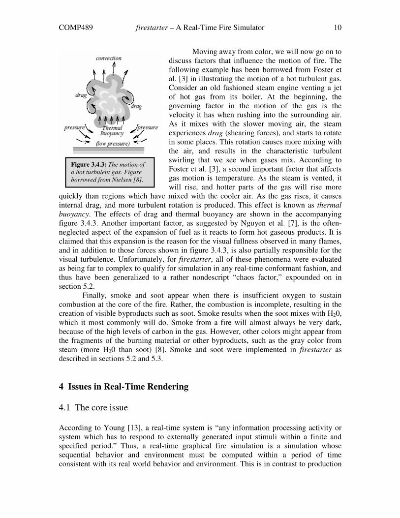
The interaction of color and temperature can be
observed by viewing a lit candle, not unlike the one
shown in figure 3.4.2. The part of the flame closest to the
wick is invisible, changing to a bluish color at the border
of the base of the flame. At the hottest point, the flame is
white. It then stays at a light yellow for some time, and
eventually merges into orange and possibly red at the tip.
A quick comparison of the candle flame colors and the black body palette highlights the
shortcomings of the palette, because the palette is not specifically geared towards the
rendering of a wax-fuelled flame. firestarter attempts to remedy this by allowing the user
some limited customization control over the palette that is used during the simulation, as
is elaborated in section 5.3.
Figure 3.4.1: The black body palette, a widely used
approximation for the light perceived from carbon-
based combustion. Figure borrowed from Nielsen [8].
Figure 3.4.2: A candle flame.
COMP489 firestarter – A Real-Time Fire Simulator 10
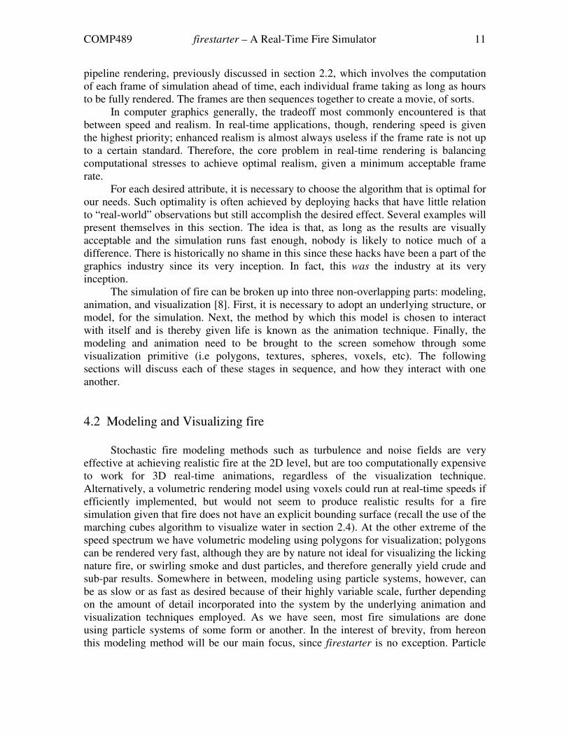
Moving away from color, we will now go on to
discuss factors that influence the motion of fire. The
following example has been borrowed from Foster et
al. [3] in illustrating the motion of a hot turbulent gas.
Consider an old fashioned steam engine venting a jet
of hot gas from its boiler. At the beginning, the
governing factor in the motion of the gas is the
velocity it has when rushing into the surrounding air.
As it mixes with the slower moving air, the steam
experiences drag (shearing forces), and starts to rotate
in some places. This rotation causes more mixing with
the air, and results in the characteristic turbulent
swirling that we see when gases mix. According to
Foster et al. [3], a second important factor that affects
gas motion is temperature. As the steam is vented, it
will rise, and hotter parts of the gas will rise more
quickly than regions which have mixed with the cooler air. As the gas rises, it causes
internal drag, and more turbulent rotation is produced. This effect is known as thermal
buoyancy. The effects of drag and thermal buoyancy are shown in the accompanying
figure 3.4.3. Another important factor, as suggested by Nguyen et al. [7], is the often-
neglected aspect of the expansion of fuel as it reacts to form hot gaseous products. It is
claimed that this expansion is the reason for the visual fullness observed in many flames,
and in addition to those forces shown in figure 3.4.3, is also partially responsible for the
visual turbulence. Unfortunately, for firestarter, all of these phenomena were evaluated
as being far to complex to qualify for simulation in any real-time conformant fashion, and
thus have been generalized to a rather nondescript “chaos factor,” expounded on in
section 5.2.
Finally, smoke and soot appear when there is insufficient oxygen to sustain
combustion at the core of the fire. Rather, the combustion is incomplete, resulting in the
creation of visible byproducts such as soot. Smoke results when the soot mixes with H20,
which it most commonly will do. Smoke from a fire will almost always be very dark,
because of the high levels of carbon in the gas. However, other colors might appear from
the fragments of the burning material or other byproducts, such as the gray color from
steam (more H20 than soot) [8]. Smoke and soot were implemented in firestarter as
described in sections 5.2 and 5.3.
4 Issues in Real-Time Rendering
4.1 The core issue
According to Young [13], a real-time system is “any information processing activity or
system which has to respond to externally generated input stimuli within a finite and
specified period.” Thus, a real-time graphical fire simulation is a simulation whose
sequential behavior and environment must be computed within a period of time
consistent with its real world behavior and environment. This is in contrast to production
Figure 3.4.3: The motion of
a hot turbulent gas. Figure
borrowed from Nielsen [8].
COMP489 firestarter – A Real-Time Fire Simulator 11
pipeline rendering, previously discussed in section 2.2, which involves the computation
of each frame of simulation ahead of time, each individual frame taking as long as hours
to be fully rendered. The frames are then sequences together to create a movie, of sorts.
In computer graphics generally, the tradeoff most commonly encountered is that
between speed and realism. In real-time applications, though, rendering speed is given
the highest priority; enhanced realism is almost always useless if the frame rate is not up
to a certain standard. Therefore, the core problem in real-time rendering is balancing
computational stresses to achieve optimal realism, given a minimum acceptable frame
rate.
For each desired attribute, it is necessary to choose the algorithm that is optimal for
our needs. Such optimality is often achieved by deploying hacks that have little relation
to “real-world” observations but still accomplish the desired effect. Several examples will
present themselves in this section. The idea is that, as long as the results are visually
acceptable and the simulation runs fast enough, nobody is likely to notice much of a
difference. There is historically no shame in this since these hacks have been a part of the
graphics industry since its very inception. In fact, this was the industry at its very
inception.
The simulation of fire can be broken up into three non-overlapping parts: modeling,
animation, and visualization [8]. First, it is necessary to adopt an underlying structure, or
model, for the simulation. Next, the method by which this model is chosen to interact
with itself and is thereby given life is known as the animation technique. Finally, the
modeling and animation need to be brought to the screen somehow through some
visualization primitive (i.e polygons, textures, spheres, voxels, etc). The following
sections will discuss each of these stages in sequence, and how they interact with one
another.
4.2 Modeling and Visualizing fire
Stochastic fire modeling methods such as turbulence and noise fields are very
effective at achieving realistic fire at the 2D level, but are too computationally expensive
to work for 3D real-time animations, regardless of the visualization technique.
Alternatively, a volumetric rendering model using voxels could run at real-time speeds if
efficiently implemented, but would not seem to produce realistic results for a fire
simulation given that fire does not have an explicit bounding surface (recall the use of the
marching cubes algorithm to visualize water in section 2.4). At the other extreme of the
speed spectrum we have volumetric modeling using polygons for visualization; polygons
can be rendered very fast, although they are by nature not ideal for visualizing the licking
nature fire, or swirling smoke and dust particles, and therefore generally yield crude and
sub-par results. Somewhere in between, modeling using particle systems, however, can
be as slow or as fast as desired because of their highly variable scale, further depending
on the amount of detail incorporated into the system by the underlying animation and
visualization techniques employed. As we have seen, most fire simulations are done
using particle systems of some form or another. In the interest of brevity, from hereon
this modeling method will be our main focus, since firestarter is no exception. Particle
COMP489 firestarter – A Real-Time Fire Simulator 12
systems allow 3D behavior to be modeled in an intuitive and non-complex manner,
although naturally they have their own share of problems as discussed below.
One problem with particle systems is that, by themselves, they assume the same
environment for all particles in the system. A solution to this is to subdivide the
environment into smaller pieces called fields [8]. A field contains information particular
to a certain portion of the scene, which is typically bounded in the form of a cube, a
rectangular prism, or other shape that can be patterned to form a mosaic with the
environment. Fields, however, find their bane in memory usage. Ideally, the grid should
surround the entire scene capable of being affected*, but the cubes should be small
enough to make the fields have a meaningful impact on the simulation. This is a hard
balance to strike, since placing as few as 10 field cubes across a single dimension in a
cubic scene amounts to 103 = 1000 fields, where individual calculations need to be made
for each field at every frame. Yet even this number is a conservative estimate since the
environment of a fire simulation is typically not cubic in shape, and thus the height is
often significantly greater than the width/depth.
A second problem with particle systems is that, in their most primitive form, they
require an enormous number of particles to fully simulate a physical system, since ideally
we would be dealing with particle interactions at a molecular level. Clearly, we must
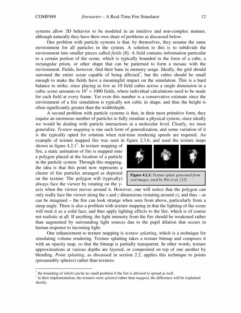
generalize. Texture mapping is one such form of generalization, and some variation of it
is the typically opted for solution when real-time rendering speeds are required. An
example of texture mapped fire was seen in figure 2.3.6, and used the texture maps
shown in figure 4.2.1†. In texture mapping of
fire, a static animation of fire is mapped onto
a polygon placed at the location of a particle
in the particle system. Through this mapping,
the idea is that this point now represents a
cluster of fire particles arranged as depicted
on the texture. The polygon will (typically)
always face the viewer by rotating on the y-
axis when the viewer moves around it. However, one will notice that the polygon can
only really face the viewer along the x and z dimensions (rotating around y), and thus – as
can be imagined – the fire can look strange when seen from above, particularly from a
steep angle. There is also a problem with texture mapping in that the lighting of the scene
will treat it as a solid face, and thus apply lighting effects to the fire, which is of course
not realistic at all. If anything, the light intensity from the fire should be weakened rather
than augmented by surrounding light sources due to the pupil dilation that occurs in
human response to incoming light.
One enhancement to texture mapping is texture splatting, which is a technique for
simulating volume rendering. Texture splatting takes a texture bitmap and composes it
with an opacity map, so that the bitmap is partially transparent. In other words, texture
approximations at various depths are layered, or composited on top of one another by
blending. Point splatting, as discussed in section 2.2, applies this technique to points
(presumably spheres) rather than textures.
* the bounding of which can be no small problem if the fire is allowed to spread as well.
† in their implementation, the textures were splatted rather than mapped, the difference will be explained
shortly.
Figure 4.2.1: Texture splats generated from
real images, used by Wei et al. [12].
COMP489 firestarter – A Real-Time Fire Simulator 13
Another enhancement to texture mapping is that, rather than consistently reusing
the same texture map/splat on the same particle polygon, pictures of real fire can be
sequenced onto polygons to lessen the static element, and make the fire look more
mobile. This technique is claimed to yield very convincing results [8], although no visual
examples could actually be found in the literature.
The observant reader will notice that the above method effectively incorporates
prerendered aspects (textures and movie clips) into a real-time simulation*. Similarly, one
could also argue that, by incorporating 2D textures, the simulation is not a truly 3D
simulation anymore. These are example of the hacks discussed in the opening section of
this chapter. Textures do not have any real world analogue, and are thus a hack, in the full
sense of the word. Textures blur the 2D/3D distinction, although the use of 2D rendering
in a 3D environment is most common given its comparatively much lower time
complexity. As discussed in sections 5.1 and 5.3, firestarter is such a 2D/3D hybrid,
although it also incorporates a volumetric aspect.
4.3 Animating fire
There are many ways in which fire can be animated. Among them, approaches using
differential equations can produce accurate animations, but necessitate the tracking of a
large number of variables. The simulations they produce are also difficult to control
because their parameters are physical constants whose relationship to the desired visual
effect is usually hard to ascertain. Additionally, the values of many parameters need to be
guessed, since our understanding of fire is incomplete. Most importantly, however, this
modeling technique is almost always computationally infeasible at the real-time level.
The solution is typically some attempt at capturing the most important physical properties
of the phenomenon, as highlighted in section 3.4, and then concocting an implementation
for each of those properties that is both as efficient and realistic as possible. The goal is
that the implementations are believable enough that they do not appear to be too ad hoc,
and therefore just another hack. Inevitably, they will be just another hack, but we would
naturally prefer elegant ones wherever possible.
4.4 Motion blurring
An argument put forth by Beaudoin et al. [2] is that, although particle sets succeed in
picturing the fuzzy, bumpy boundaries of clouds (for instance), they fail to show the
characteristically crisp, sleek outlines of actual flame. This is true in that at any instant in
time, flames do have a crisp, sleek outline. Yet when we see flame, we do not see it at an
instant in time. Rather, we see it as it exists over some period of time, resulting in an
important visual effect known as motion blur.
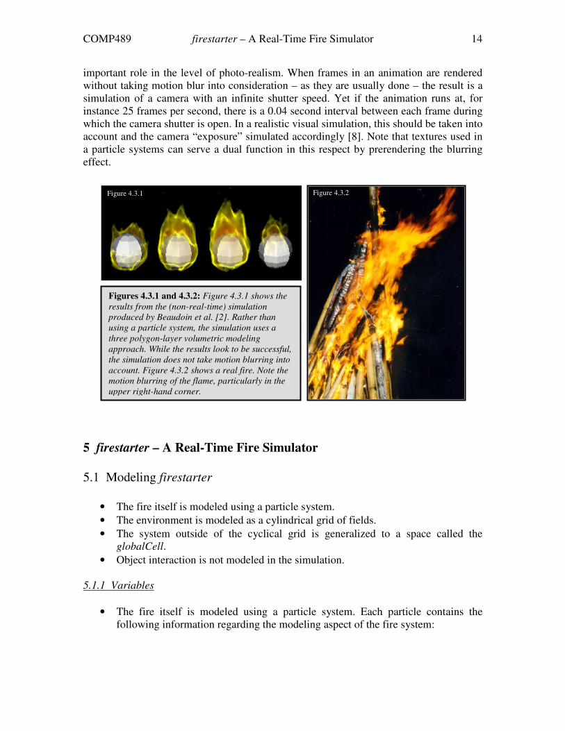
As the name implies, motion blur is a blurring of objects that move relatively to the
viewer, and is demonstrated for the case of fire in figure 4.3.2. In all computer graphics
systems that simulate moving objects, the shutter speed of the virtual camera plays an
* the simulation remains real-time because the prerendered aspects are reused
COMP489 firestarter – A Real-Time Fire Simulator 14
important role in the level of photo-realism. When frames in an animation are rendered
without taking motion blur into consideration – as they are usually done – the result is a
simulation of a camera with an infinite shutter speed. Yet if the animation runs at, for
instance 25 frames per second, there is a 0.04 second interval between each frame during
which the camera shutter is open. In a realistic visual simulation, this should be taken into
account and the camera “exposure” simulated accordingly [8]. Note that textures used in
a particle systems can serve a dual function in this respect by prerendering the blurring
effect.
5 firestarter – A Real-Time Fire Simulator
5.1 Modeling firestarter
• The fire itself is modeled using a particle system.
• The environment is modeled as a cylindrical grid of fields.
• The system outside of the cyclical grid is generalized to a space called the
globalCell.
• Object interaction is not modeled in the simulation.
5.1.1 Variables
• The fire itself is modeled using a particle system. Each particle contains the
following information regarding the modeling aspect of the fire system:
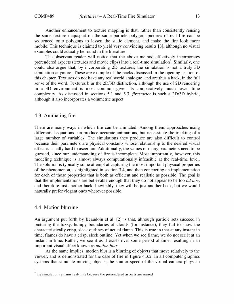
Figures 4.3.1 and 4.3.2: Figure 4.3.1 shows the
results from the (non-real-time) simulation
produced by Beaudoin et al. [2]. Rather than
using a particle system, the simulation uses a
three polygon-layer volumetric modeling
approach. While the results look to be successful,
the simulation does not take motion blurring into
account. Figure 4.3.2 shows a real fire. Note the
motion blurring of the flame, particularly in the
upper right-hand corner.
Figure 4.3.1 Figure 4.3.2
COMP489 firestarter – A Real-Time Fire Simulator 15
o death – the time at which the particle dies. After this time expires, the
death is reset to a new value and the particle is reborn at the base of the
flame.
o x, y, z – the 3D coordinate set of the particle at a given point in time.
o currentCell – a pointer to the environment cell in which the particle is
currently present.
o xOrigin, zOrigin – the points at which the particle originated. The
particle’s position is reset to this coordinate pair at the base of the flame
when the particle is reborn (see death).
o cellOrigin – a pointer to the environment cell in which the particle
originated.
• The environment is modeled as a cylindrical grid of fields. Each field in the
environment is referred to as a cell in the code of the simulation. Each cell
contains the following attributes relating to the modeling aspect of the
environment:
o x, height, z – the 3D coordinate set of the central point of the cell.
o population – the number of particles presently located in the cell.
o particleList – a pointer to a linked list data structure containing pointers
to the particles located in the cell.
o topCell – a pointer to the cell directly above this cell, if any.
o leftCell, rightCell, frontCell, rearCell – pointers to the cells directly
adjacent to the current cell, if any.
o leftFrontCell, leftRearCell, rightFrontCell, rightRearCell – pointers to
the cells diagonally adjacent to the current cell, if any.
• The system outside of the cyclical grid is generalized as a cell called the
globalCell. This “cell” renders all smoke particles, which become relegated from
the above system (see animation), and contains all particles that have crossed the
boundary of the environmental cylinder and are therefore no longer considered
part of the system, and are subsequently not rendered until they die and are
reborn.
5.1.2 User Preset Constants
• PARTICLES – the number of particles in the system.
• GRID_HEIGHT – the height of the cylindrical cell grid.
• GRID_DIAMETER – the diameter of the cylindrical cell grid.
• CELL_HEIGHT – the height of the grid cells (the y direction).
• CELL_WIDTH – the width of the grid cells (the x and z directions).
5.2 Animating firestarter
• Particles are born, or created, at the base of the cell grid system, within a certain
radius of the grid system known as the “fuel radius.” The ratio of the fuel radius
COMP489 firestarter – A Real-Time Fire Simulator 16
to the cell grid radius is tunable by the user before the start of the simulation, but
should be less than one for obvious reasons (see 5.2.3).
• Fire particle have a life specified by a user-controlled constant, after which time
they are “reborn”.
• Fire particles have a vertical velocity determined by a combination of the
temperature of the cell in which the particle is located, and the aggregate speed
modifier of the particle (each particle has a predisposed upward inclination). Both
of these effects can be modified through two user-controlled constants.
• Fire particles have a horizontal velocity that is randomized and specific to the cell
in which the particle is positioned. The randomization is context sensitive, and the
degree is controlled by two user-controlled constants.
• Each frame, fire particles are checked against their position to determine if they
have propagated into a new cell.
• Each frame, fire particles can potentially become smoke particles with a certain
probability that is determined by a user-controlled constant. The probability
increases as the particle rises higher.
• Smoke particles are advanced according to their momentum at the point at which
the particles became smoke. Per frame, the upward velocity increases modeling
the buoyancy effect, and the horizontal velocity decreases modeling the effect of
air resistance. The degree of these velocity modifiers is controlled by a single
user-controlled constant.
• One of the particularly redeeming qualities of the simulation is that it is frame rate
sensitive. In other words, the simulation monitors the frame rate and calibrates its
behavior accordingly, so that the fire’s behavior is characterized along a per
second basis, as opposed to a per frame basis. This is very effective at containing
the simulation and having it appear as it was designed regardless of the frame rate
(barring extremes).
5.2.1 Variables
• Each particle contains the following variables pertaining to the animation aspect
of the simulation:
o ∆x, ∆y, ∆z – the 3D velocity vector of the particle at the last frame (used
to store momentum information for smoke particles).
o smoke – a Boolean indicating whether or not the particle is to be
rendered as smoke if outside the environmental grid system.
o speed – the predisposed upward velocity inclination of the particle.
Generated using BUOYANCY_RANDOMNESS (see 5.2.2)
• Each cell contains the following information pertaining to the animation aspect of
the simulation:
o xVector, zVector – the x and z velocity vectors of all particles in that cell
at a particular frame in the simulation.
o temperature – for all intents and purposes, this is the y velocity vector of
all particles in the cell, although this vector is modified by the speed
COMP489 firestarter – A Real-Time Fire Simulator 17
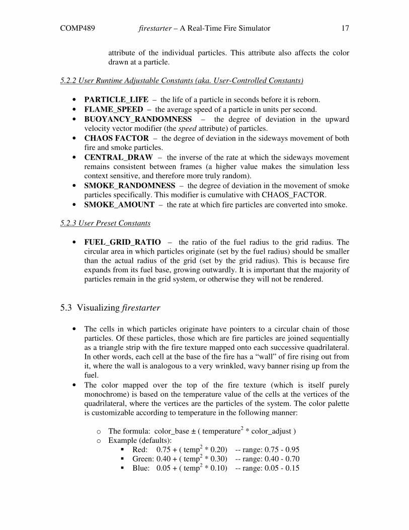
attribute of the individual particles. This attribute also affects the color
drawn at a particle.
5.2.2 User Runtime Adjustable Constants (aka. User-Controlled Constants)
• PARTICLE_LIFE – the life of a particle in seconds before it is reborn.
• FLAME_SPEED – the average speed of a particle in units per second.
• BUOYANCY_RANDOMNESS – the degree of deviation in the upward
velocity vector modifier (the speed attribute) of particles.
• CHAOS FACTOR – the degree of deviation in the sideways movement of both
fire and smoke particles.
• CENTRAL_DRAW – the inverse of the rate at which the sideways movement
remains consistent between frames (a higher value makes the simulation less
context sensitive, and therefore more truly random).
• SMOKE_RANDOMNESS – the degree of deviation in the movement of smoke
particles specifically. This modifier is cumulative with CHAOS_FACTOR.
• SMOKE_AMOUNT – the rate at which fire particles are converted into smoke.
5.2.3 User Preset Constants
• FUEL_GRID_RATIO – the ratio of the fuel radius to the grid radius. The
circular area in which particles originate (set by the fuel radius) should be smaller
than the actual radius of the grid (set by the grid radius). This is because fire
expands from its fuel base, growing outwardly. It is important that the majority of
particles remain in the grid system, or otherwise they will not be rendered.
5.3 Visualizing firestarter
• The cells in which particles originate have pointers to a circular chain of those
particles. Of these particles, those which are fire particles are joined sequentially
as a triangle strip with the fire texture mapped onto each successive quadrilateral.
In other words, each cell at the base of the fire has a “wall” of fire rising out from
it, where the wall is analogous to a very wrinkled, wavy banner rising up from the
fuel.
• The color mapped over the top of the fire texture (which is itself purely
monochrome) is based on the temperature value of the cells at the vertices of the
quadrilateral, where the vertices are the particles of the system. The color palette
is customizable according to temperature in the following manner:
o The formula: color_base ± ( temperature2 * color_adjust )
o Example (defaults):
� Red: 0.75 + ( temp2 * 0.20) -- range: 0.75 - 0.95
� Green: 0.40 + ( temp2 * 0.30) -- range: 0.40 - 0.70
� Blue: 0.05 + ( temp2 * 0.10) -- range: 0.05 - 0.15
COMP489 firestarter – A Real-Time Fire Simulator 18
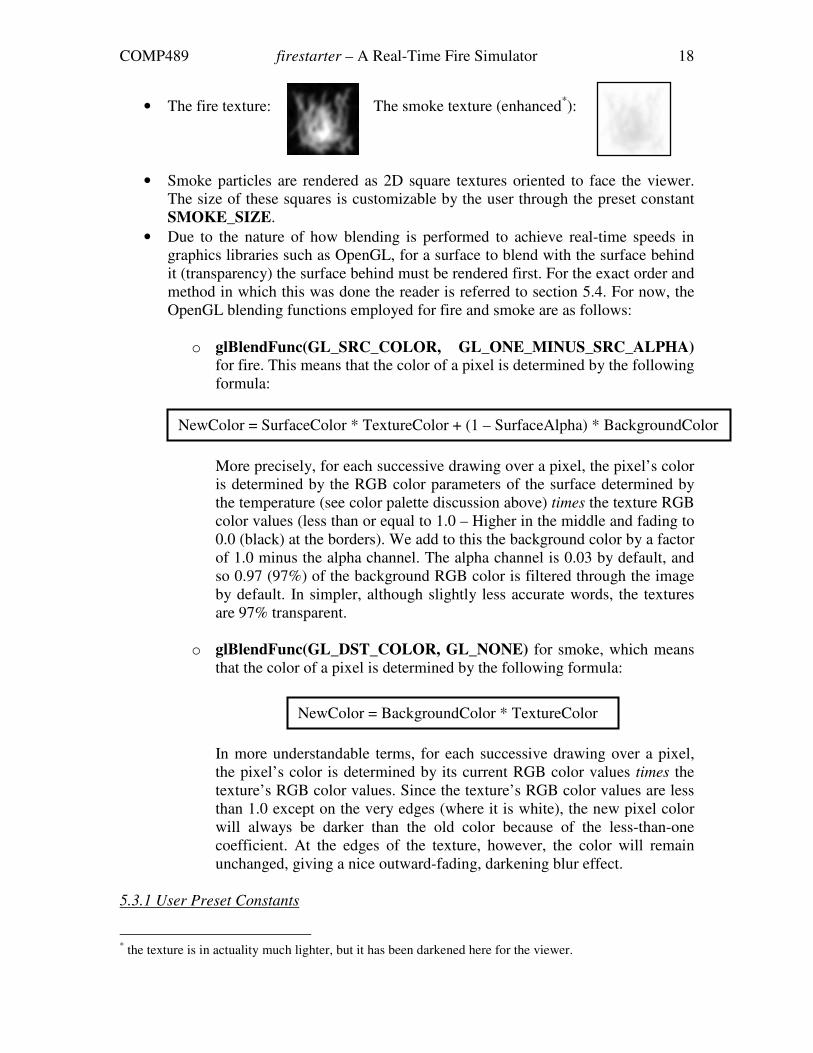
• The fire texture: The smoke texture (enhanced*):
• Smoke particles are rendered as 2D square textures oriented to face the viewer.
The size of these squares is customizable by the user through the preset constant
SMOKE_SIZE.
• Due to the nature of how blending is performed to achieve real-time speeds in
graphics libraries such as OpenGL, for a surface to blend with the surface behind
it (transparency) the surface behind must be rendered first. For the exact order and
method in which this was done the reader is referred to section 5.4. For now, the
OpenGL blending functions employed for fire and smoke are as follows:
o glBlendFunc(GL_SRC_COLOR, GL_ONE_MINUS_SRC_ALPHA) for fire. This means that the color of a pixel is determined by the following
formula:
More precisely, for each successive drawing over a pixel, the pixel’s color
is determined by the RGB color parameters of the surface determined by
the temperature (see color palette discussion above) times the texture RGB
color values (less than or equal to 1.0 – Higher in the middle and fading to
0.0 (black) at the borders). We add to this the background color by a factor
of 1.0 minus the alpha channel. The alpha channel is 0.03 by default, and
so 0.97 (97%) of the background RGB color is filtered through the image
by default. In simpler, although slightly less accurate words, the textures
are 97% transparent.
o glBlendFunc(GL_DST_COLOR, GL_NONE) for smoke, which means
that the color of a pixel is determined by the following formula:
In more understandable terms, for each successive drawing over a pixel,
the pixel’s color is determined by its current RGB color values times the
texture’s RGB color values. Since the texture’s RGB color values are less
than 1.0 except on the very edges (where it is white), the new pixel color
will always be darker than the old color because of the less-than-one
coefficient. At the edges of the texture, however, the color will remain
unchanged, giving a nice outward-fading, darkening blur effect.
5.3.1 User Preset Constants
* the texture is in actuality much lighter, but it has been darkened here for the viewer.
NewColor = SurfaceColor * TextureColor + (1 – SurfaceAlpha) * BackgroundColor
NewColor = BackgroundColor * TextureColor
COMP489 firestarter – A Real-Time Fire Simulator 19
• FIRE_BITMAP – the bitmap to use for the fire. Recommended lighter in the
center and darker towards the edges. A brighter bitmap will yield brighter results
and may reduce the number of particles necessary to achieve a desired visual.
• SMOKE_BITMAP – the bitmap to use for the smoke. Recommended darker in
the center fading to white at the edges. A darker bitmap will yield the appearance
of denser smoke and soot.
• FIRE_R_BASE / FIRE_G_BASE / FIRE_B_BASE – the base RGB color
components (see color palette discussion above).
• FIRE_R_VARIABLE / FIRE_G_ VARIABLE / FIRE_B_ VARIABLE – the
variable RGB color component (see color palette discussion above).
• FIRE_ALPHA_CHANNEL – the degree of color contribution of the
background elements for visualizing the fire. A higher value will yield brighter
fire.
5.4 Algorithm Specifics
The simulation algorithm is as follows:
1. Initialization:
a. Set up the OpenGL environment.
b. Load the textures into memory.
c. Initialize the cell data.
i. Count the number of cells to be created given the specified grid
bounds.
ii. Establish cell position and orientation with respect to one another
using the breadth first search algorithm.
d. Initialize the particle data.
2. Rendering loop:
a. Position the viewer.
b. Draw the environment.*
c. Determine the angle of view relative to the fire. If the fire is not in view,
then do not perform the remainder of the loop and return to 2a. This
prevents any unnecessary calculations being performed on the fire while it
is not being rendered to the screen.
d. Sort the cells by distance from the viewer for proper blending (see 5.4.1)
e. Perform animation computations on the cells and the particles they contain
f. Draw the cells in sorted order, rendering the particles that they contain to
the screen.
g. Loop to 2a.
* The torch is the default. If someone were to abstract the fire simulator into a class, then the simulator
would be a component of the scene and this part of the algorithm would be removed.
COMP489 firestarter – A Real-Time Fire Simulator 20
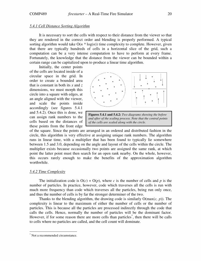
5.4.1 Cell Distance Sorting Algorithm
It is necessary to sort the cells with respect to their distance from the viewer so that
they are rendered in the correct order and blending is properly performed. A typical
sorting algorithm would take O(n * log(n)) time complexity to complete. However, given
that there are typically hundreds of cells in a horizontal slice of the grid, such a
computation can be a very intense computation to have to perform at every frame.
Fortunately, the knowledge that the distance from the viewer can be bounded within a
certain range can be capitalized upon to produce a linear time algorithm.
Initially, the center points
of the cells are located inside of a
circular space in the grid. In
order to create a bounded area
that is constant in both its x and z
dimensions, we must morph this
circle into a square with edges, at
an angle aligned with the viewer,
and scale the points inside
accordingly (see figures 5.4.1
and 5.4.2). Once this is done, we
can assign rank numbers to the
cells based on the distances of
these points from the front edge
of the square. Since the points are arranged in an ordered and distributed fashion in the
circle, this algorithm is very effective at assigning unique rank numbers. The algorithm
runs in linear time, with a multiplier that has been found to typically lie somewhere
between 1.5 and 3.0, depending on the angle and layout of the cells within the circle. The
multiplier exists because occasionally two points are assigned the same rank, at which
point the latter point must then search for an open rank nearby. On the whole, however,
this occurs rarely enough to make the benefits of the approximation algorithm
worthwhile.
5.4.2 Time Complexity
The initialization code is O(c) + O(p), where c is the number of cells and p is the
number of particles. In practice, however, code which traverses all the cells is run with
much more frequency than code which traverses all the particles, being run only once,
and thus the number of cells is by far the stronger determiner of the two.
Thanks to the blending algorithm, the drawing code is similarly O(max(c, p)). The
complexity is linear to the maximum of either the number of cells or the number of
particles. This is because all the particles are processed indirectly through the code that
calls the cells. Hence, normally the number of particles will be the dominant factor.
However, if for some reason there are more cells than particles*, then there will be calls
to cells where no particles are called, and the cell count will dominate.
* Not a recommended circumstance.
Figures 5.4.1 and 5.4.2: Two diagrams showing the before
and after of the scaling process. Note that the central points
of the cells are scaled along with the circle.
COMP489 firestarter – A Real-Time Fire Simulator 21
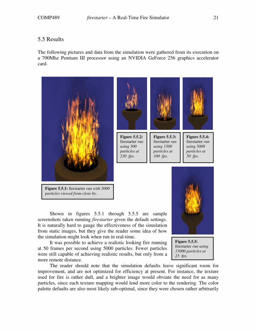
Figure 5.5.1: firestarter run with 5000
particles viewed from close by.
Figure 5.5.2: firestarter run
using 500
particles at
230 fps.
Figure 5.5.3: firestarter run
using 1500
particles at
100 fps.
Figure 5.5.4: firestarter run
using 5000
particles at
50 fps.
Figure 5.5.5: firestarter run using
15000 particles at
25 fps.
5.5 Results
The following pictures and data from the simulation were gathered from its execution on
a 700Mhz Pentium III processor using an NVIDIA GeForce 256 graphics accelerator
card.
Shown in figures 5.5.1 through 5.5.5 are sample
screenshots taken running firestarter given the default settings.
It is naturally hard to gauge the effectiveness of the simulation
from static images, but they give the reader some idea of how
the simulation might look when run in real-time.
It was possible to achieve a realistic looking fire running
at 50 frames per second using 5000 particles. Fewer particles
were still capable of achieving realistic results, but only from a
more remote distance.
The reader should note that the simulation defaults leave significant room for
improvement, and are not optimized for efficiency at present. For instance, the texture
used for fire is rather dull, and a brighter image would obviate the need for as many
particles, since each texture mapping would lend more color to the rendering. The color
palette defaults are also most likely sub-optimal, since they were chosen rather arbitrarily
COMP489 firestarter – A Real-Time Fire Simulator 22
and not analyzed for the most effective distribution. Superior blending methods may also
exist to the ones outlined in section 5.3.
As an interesting side note, Muller et al. [6] were able to speed up their simulation
by a factor of 10 by storing copies of the particle objects in the grid cells rather than
storing references to those particles. This doubled memory consumption, but greatly
enhanced the proximity in memory of the information needed for interpolation, causing a
subsequently large increase in the cache hit rate. firestarter does not exercise this degree
of low level control, but a factor of 10 does seem rather appealing and so this is a
promising area for future addition.*
6 Conclusions
It is difficult to predict how effective firestarter would be, incorporated into an
interactive application such as a computer game. Computer games are the interactive
realm to which it would most likely be destined given that it does not interact with other
objects in the environment; firestarter would only be useful in a scene where the fire is
acting as an ancillary entity – where the fire is not the focus of attention, but nonetheless
adds aesthetic realism to the scene. †
It has been demonstrated that doubling the number of particles roughly halves the
frame rate (this is consistent with the complexity analysis), and thus having multiple fires
in the view of the user would place a severe strain on the application. Thus, it would
appear that the strains are presently too great for the inclusion of firestarter into a
complex environmental scene where it is not part of the focal point of a scene. On the
other hand, the computer on which these test runs were executed is roughly five years
behind modern-day state of the art computer systems. Most significantly, the GeForce
256 is several generations behind newer graphics cards available at the time of this
writing, where 3D graphics acceleration is a field of computer graphics that has made
considerable leaps in recent years.
Nonetheless, the simulation has been by and large successful in accomplishing the
goals set at its inception. A new visualization technique has been introduced into the
literature, which will potentially provide inspiration for other ideas heading into the
future. firestarter is a worthy first attempt at modeling a highly complex system, and
given that it is at present highly customizable, it may yet make a significant contribution,
should people’s curiosities be piqued.
* Note that if firestarter were integrated into a real-time interactive program where the fire was peripheral
to the scene, then the performance increase might not be quite as realizable due to other components of the
application also utilizing cache resources. † This would not be the case in, for instance, a fire simulator for firemen, or an educational tool for a
chemistry class.
COMP489 firestarter – A Real-Time Fire Simulator 23
7 References
[1] Angel, E. (2002). Interactive Computer Graphics: A Top-Down Approach with
OpenGL (3rd
Edition). Pearson Addison Wesley : Reading, MA. 2002.
[2] Beaudoin, P., Paquet, S. (2001). “Realistic and controllable fire simulation.”
Proceedings of Graphics Interface 2001, pages 159-166.
[3] Foster N., Metaxas D. (1997). “Modeling the motion of a hot, turbulent gas.”
Proceedings of the 24th annual conference on Computer graphics and interactive
techniques, August 1997.
[4] Lamorlette A., Foster N. (2002). “Structural modeling of flames for a production
environment”, Proceedings of the 29th annual conference on Computer graphics
and interactive techniques, San Antonio, Texas, July 2002.
[5] Lee, H., Kim, L., Meyer M., Desbrun, M. (2001). “Meshes on fire.” EG Workshop
on Computer Animation and Simulation, pages 75-84, September 2001.
[6] Müller, M., Charypar, D., Gross, M. (2003). “Particle-based fluid simulation for
interactive applications.” Proceedings of the 2003 ACM SIGGRAPH Symposium
on Computer Animation, San Diego, California, 2003.
[7] Nguyen, D., Fedkiw R., Jensen H. (2002). “Physically based modeling and
animation of fire.” Proceedings of the 29th annual conference on computer
graphics and interactive techniques, San Antonio, Texas, July 2002.
[8] Nielsen, T. E. (1999). “Modeling, animation, and visualization of fire.” Master's
thesis, University of Copenhagen, Denmark, April 1999.
[9] Perry, C. H., Picard, R. W. (1994). Synthesizing flames and their spreading.
Proceedings of the Fifth Eurographics Workshop on Animation and Simulation,
pages 1-14, September 1994.
[10] Reeves W. T. (1983). “Particle systems — a technique for modeling a class of
fuzzy objects.” Proceedings of the 10th annual conference on Computer graphics
and interactive techniques, Detroit, Michigan, July 1983.
[11] US Army (1971). “Chapter 3: characteristics, chemistry, and physics of fire.”
Publication TM 5-315: Firefighting and Rescue Procedures in Theaters of
Operation. US Army Corps of Engineers Internet Publishing Group. April 1971.
[12] Wei X., Li, W., Mueller, K., Kaufman, A. (2002). “Simulating fire with texture
splats.” Proceedings of the conference on Visualization '02, October 27-November
01, 2002, Boston, Massachusetts

COMP489 firestarter – A Real-Time Fire Simulator 24
[13] Young, S. (1982). Real Time Languages: Design and Development, Ellis Horwood
Publishers, Chichester, UK. 1982.