final detailed design review - rochester institute …edge.rit.edu/edge/p15551/public/systems level...
TRANSCRIPT
Final Detailed Design ReviewHigh Temperature Pellet Based 3D Printer Head (P15551)Team Members: Alyssa Palmieri, Ray Ali, James Allen, Kylan Ames

High Temperature Pellet Based 3D Printer Head
Most current 3D printers use plastic filament as feedstock. Most current 3D printers use plastic filament as feedstock. The goal of our project is to create a 3D printer head that uses ordinary plastic injection molding pellets as feed stock. It should be able to withstand temperatures up to 380°C, which is 100°C higher than max operating temperatures of current printers, and should also be able to print for 10 hours continuously.
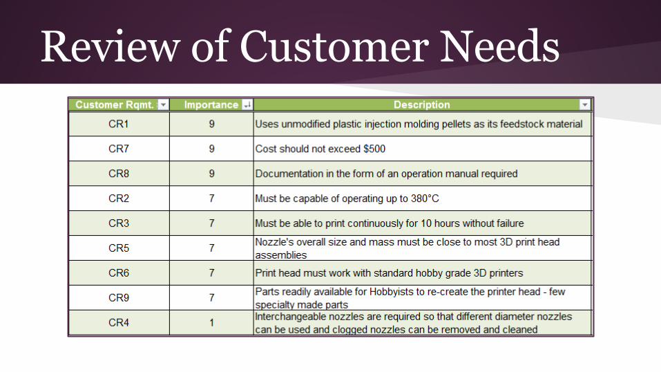
Review of Customer Needs
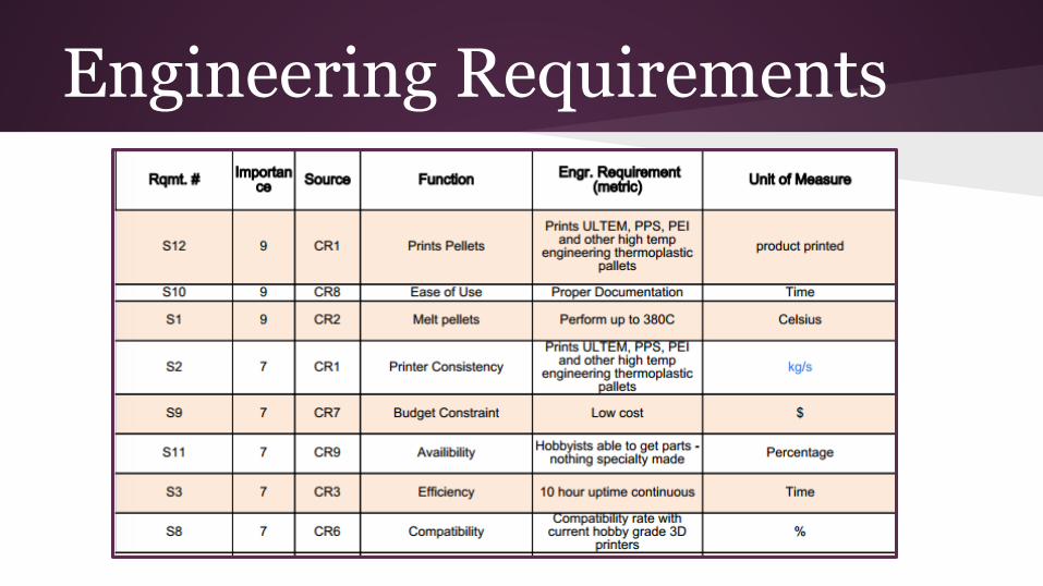
Engineering Requirements

System FunctionFunction Method
Storing: Hopper
Heater: Cartridge Heater
Cooling: Cooling Fan
Driving: Auger ScrewStepper Motor
Feedback: Thermal Feedback
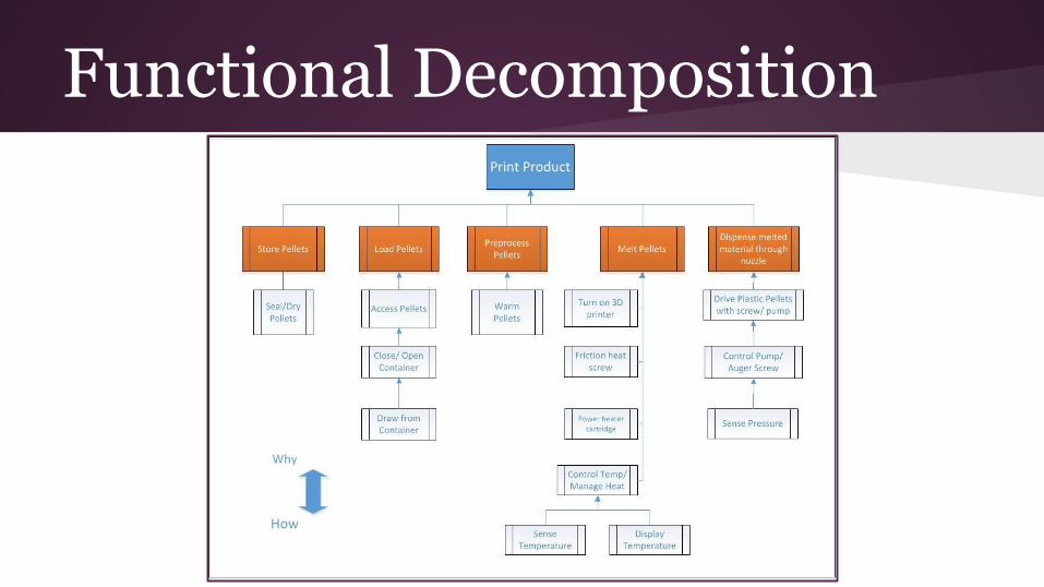
Functional Decomposition

Operating ModesOperating Modes:
Motor Heater Cartridge Cooling Fans Thermal Feedback
Heating ON
Cooling OFF
Printing Independent
Standby
Purging
Shut Down
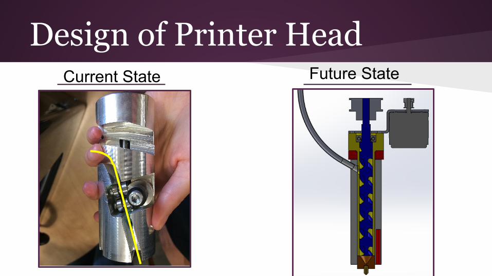
Design of Printer HeadCurrent State Future State

Print Head Design

Print Head Drawing with Components
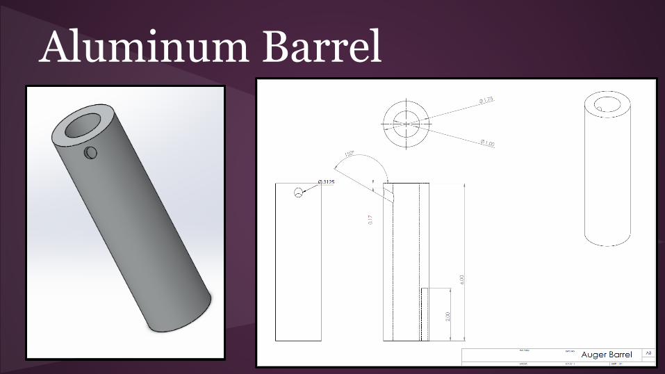
Aluminum Barrel
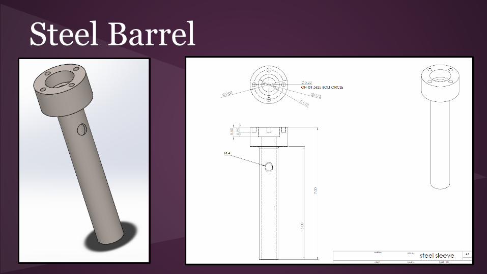
Steel Barrel

Auger Screw

Mounting Bracket
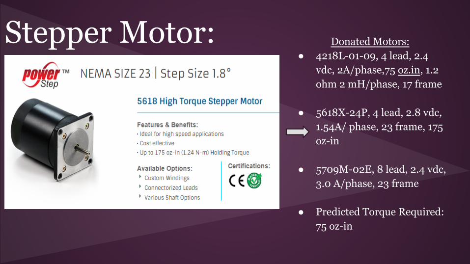
Stepper Motor: Donated Motors:● 4218L-01-09, 4 lead, 2.4
vdc, 2A/phase,75 oz.in, 1.2 ohm 2 mH/phase, 17 frame
● 5618X-24P, 4 lead, 2.8 vdc, 1.54A/ phase, 23 frame, 175 oz-in
● 5709M-02E, 8 lead, 2.4 vdc, 3.0 A/phase, 23 frame
● Predicted Torque Required: 75 oz-in
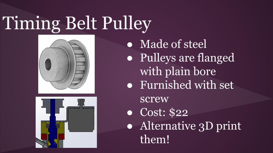
Timing Belt Pulley● Made of steel● Pulleys are flanged
with plain bore● Furnished with set
screw● Cost: $22● Alternative 3D print
them!

Nozzle Adaptor

Thermocouple
● Type-K● Glass Braid Insulation● Good up to 500 °C ● Color-coded wires● Cost: $9.95● Quantity: 2
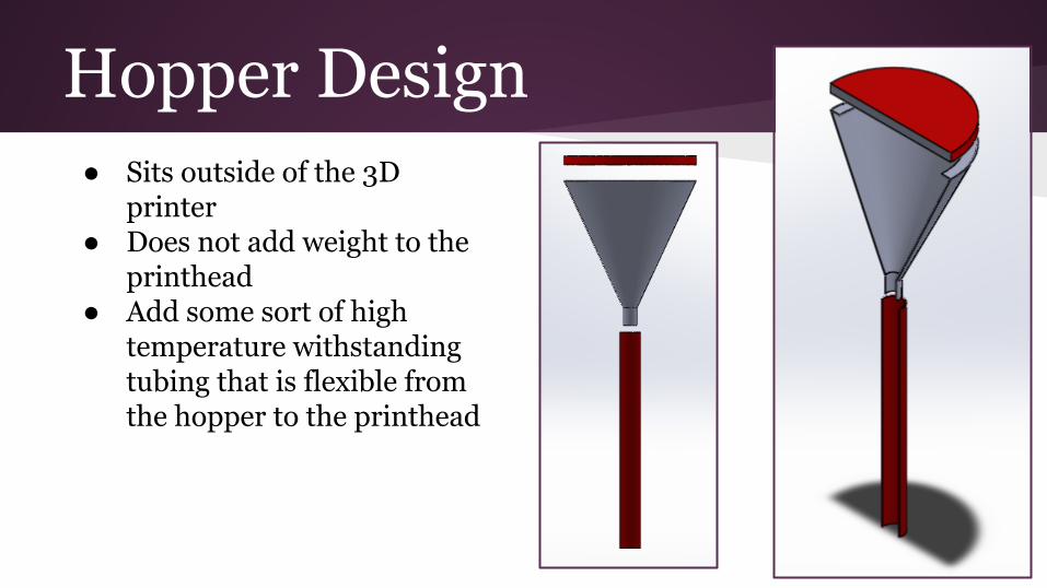
Hopper Design● Sits outside of the 3D
printer● Does not add weight to the
printhead● Add some sort of high
temperature withstanding tubing that is flexible from the hopper to the printhead
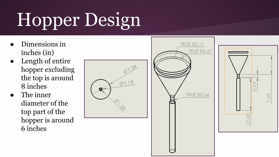
Hopper Design● Dimensions in
inches (in)● Length of entire
hopper excluding the top is around 8 inches
● The inner diameter of the top part of the hopper is around 6 inches
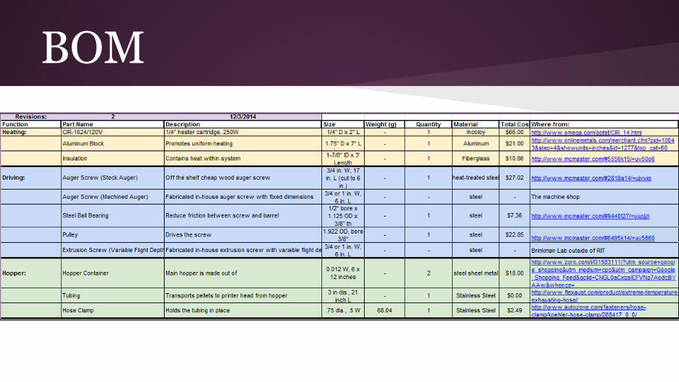
BOM
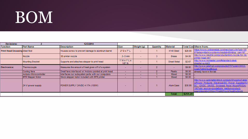
BOM
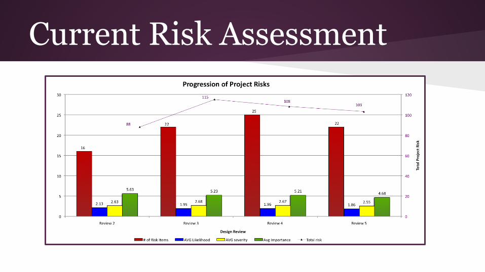
Current Risk Assessment
Test Plan: Flow Rate/ Layer Resolution
Overview:
The main objective of this test plan is to verify that the mass flow rate and layer height of the printed material to make sure it is compatible with current 3D printing capabilities.
Testing Configuration:
In order to test the flow rate the following materials are required:
1. 3D Print head2. Scale to weigh mass of extruded material3. Stopwatch4. Data sheet5. Scissors or tongs to cut filament print time has been reached

Test Plan: Flow Rate/ Layer ResolutionTest Procedure:
1. Turn 3D print head on and set to appropriate temperature2. Load 3D print head with pellets3. Simultaneously, turn print head on and start the stopwatch4. Print for known amount of time ( Recommend: 30 seconds to a min)5. Measure the amount of printed material on the scale and the diameter of the printed material and record data6. Repeat steps 1-5 for at least four trials

Test Plan: Flow Rate/ Layer ResolutionPass/fail criteria:
Theoretically, the layer height should be the diameter of the nozzle. The pass criteria will be within 5% of the diameter of the nozzle. Another pass criteria will be an appropriate mass and volumetric flow rate.
Responsibilities and the approval process:
James Allen will be responsible for running and approving the testing results. A secondary opinion will be sought at to further validate the testing results
Risks and contingencies:
● Zero flow rate through nozzle● Inconsistent diameter● Flow rate too high or low
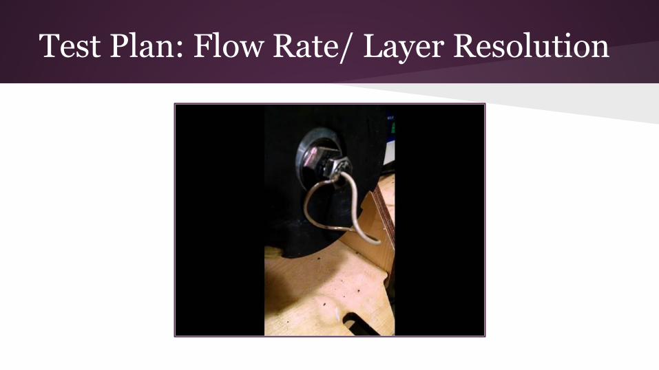
Test Plan: Flow Rate/ Layer Resolution
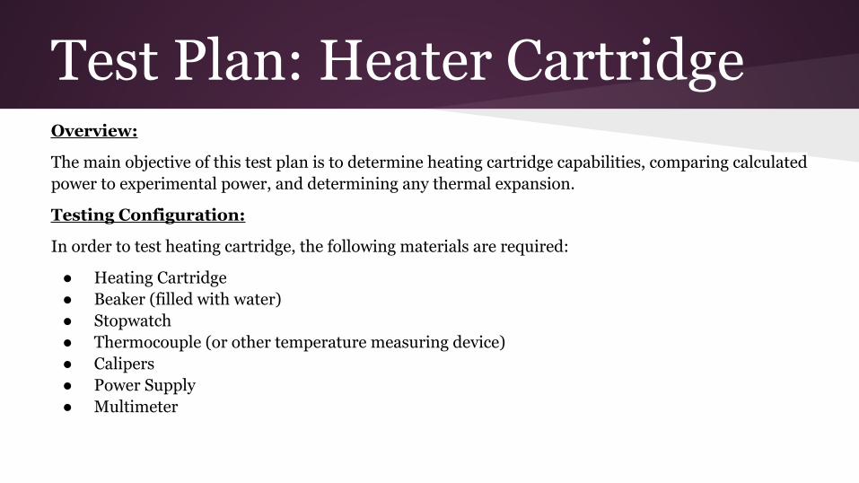
Test Plan: Heater Cartridge Overview:
The main objective of this test plan is to determine heating cartridge capabilities, comparing calculated power to experimental power, and determining any thermal expansion.
Testing Configuration:
In order to test heating cartridge, the following materials are required:
● Heating Cartridge● Beaker (filled with water)● Stopwatch● Thermocouple (or other temperature measuring device)● Calipers● Power Supply● Multimeter
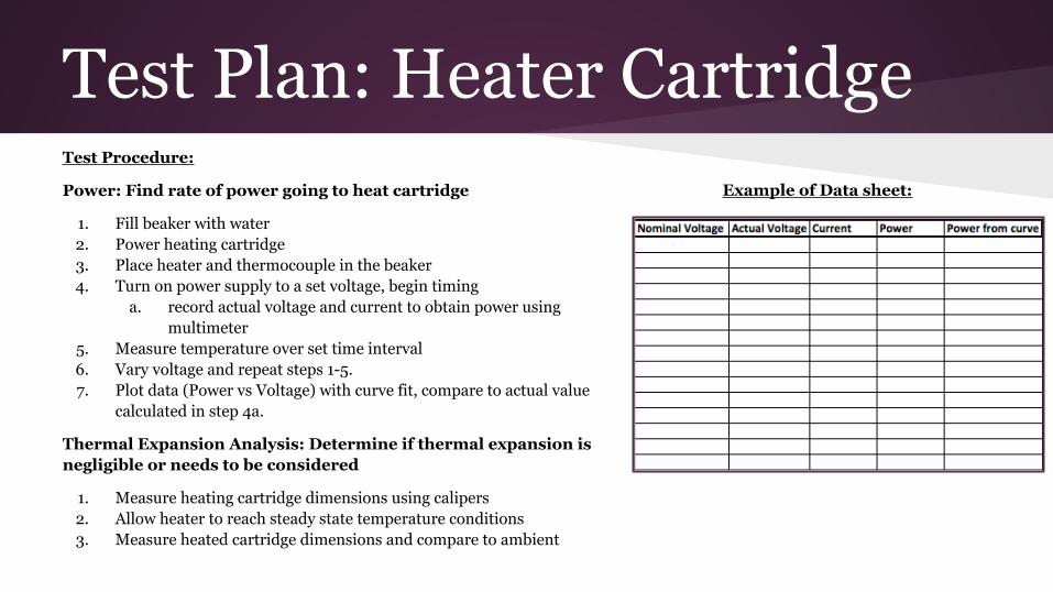
Test Plan: Heater CartridgeTest Procedure:
Power: Find rate of power going to heat cartridge
1. Fill beaker with water2. Power heating cartridge3. Place heater and thermocouple in the beaker4. Turn on power supply to a set voltage, begin timing
a. record actual voltage and current to obtain power using multimeter
5. Measure temperature over set time interval6. Vary voltage and repeat steps 1-5.7. Plot data (Power vs Voltage) with curve fit, compare to actual value
calculated in step 4a.
Thermal Expansion Analysis: Determine if thermal expansion is negligible or needs to be considered
1. Measure heating cartridge dimensions using calipers2. Allow heater to reach steady state temperature conditions3. Measure heated cartridge dimensions and compare to ambient
Example of Data sheet:

Test Plan: Heater CartridgePass/fail criteria:
Heating cartridge will fail if the power curve differs significantly from the calculated values. Percent error values of +/- 5% will be tolerable. For thermal expansion, it will be used as a metric for hole tolerances when mounting the cartridge
Responsibilities and the approval process
Kylan Ames will be responsible for running and approving the testing results. A secondary opinion will be sought at to further validate the testing results
Risks and contingencies:
● gets extremely hot● trust manufacturer specs
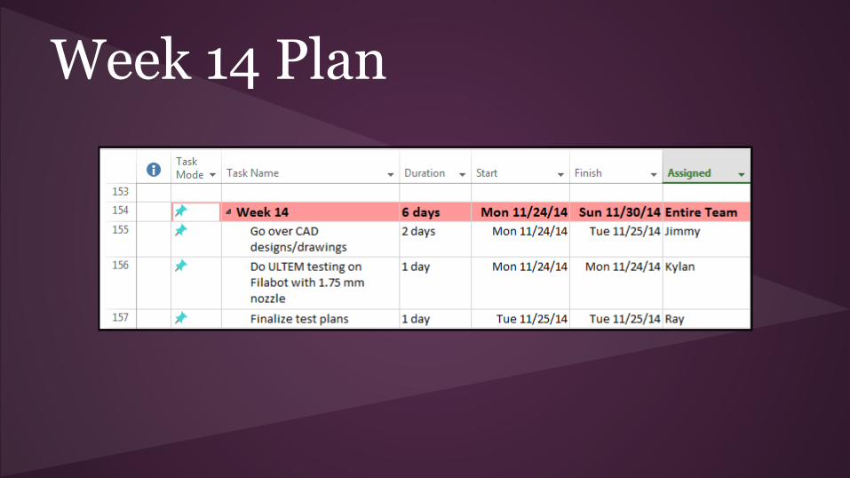
Week 14 Plan

Week15
Plan

Week 16 Plan
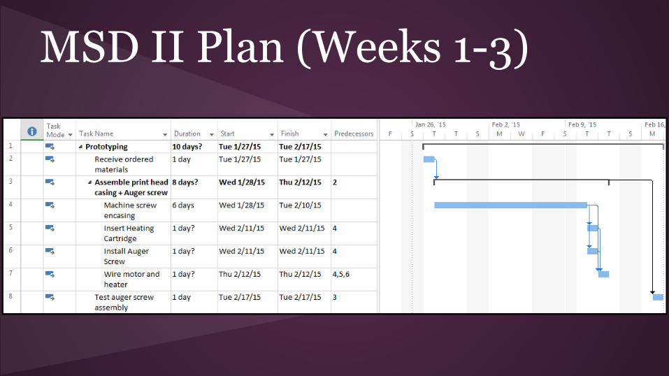
MSD II Plan (Weeks 1-3)