detailed optical design
TRANSCRIPT

Detailed Optical Design
6/27/2011 DL-NIRSP PDR, Tucson, AZ, June 23-24, 2011 76
Zemax Modeling of the Instrument
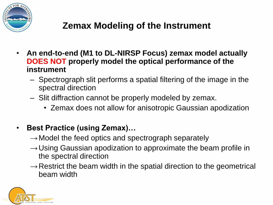
• An end-to-end (M1 to DL-NIRSP Focus) zemax model actually DOES NOT properly model the optical performance of the instrument
– Spectrograph slit performs a spatial filtering of the image in the spectral direction
– Slit diffraction cannot be properly modeled by zemax.
• Zemax does not allow for anisotropic Gaussian apodization
• Best Practice (using Zemax)…
→Model the feed optics and spectrograph separately
→Using Gaussian apodization to approximate the beam profile in the spectral direction
→Restrict the beam width in the spatial direction to the geometrical beam width

Feed Optics
6/27/2011 DL-NIRSP PDR, Tucson, AZ, June 23-24, 2011 78
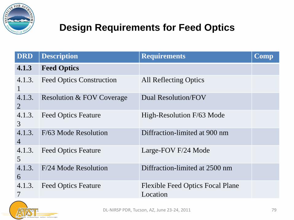
Design Requirements for Feed Optics
DRD Description Requirements Comp
4.1.3 Feed Optics
4.1.3.
1
Feed Optics Construction All Reflecting Optics
4.1.3.
2
Resolution & FOV Coverage Dual Resolution/FOV
4.1.3.
3
Feed Optics Feature High-Resolution F/63 Mode
4.1.3.
4
F/63 Mode Resolution Diffraction-limited at 900 nm
4.1.3.
5
Feed Optics Feature Large-FOV F/24 Mode
4.1.3.
6
F/24 Mode Resolution Diffraction-limited at 2500 nm
4.1.3.
7
Feed Optics Feature Flexible Feed Optics Focal Plane
Location
6/27/2011 79 DL-NIRSP PDR, Tucson, AZ, June 23-24, 2011
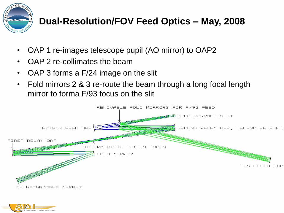
Dual-Resolution/FOV Feed Optics – May, 2008
• OAP 1 re-images telescope pupil (AO mirror) to OAP2
• OAP 2 re-collimates the beam
• OAP 3 forms a F/24 image on the slit
• Fold mirrors 2 & 3 re-route the beam through a long focal length
mirror to forma F/93 focus on the slit

Dual-Resolution Feed Optics
April 2011 – Toleranced Version
Slitjaw & Context Imager
M10 – AO DM
OAP2
F/24 OAP3
OAP1 Fold Mirror, FM1
Fold Mirror, FM2 Fold Mirror, FM3
F/63 Spherical Mirror
• OAC 1,2, & 3
– fl =4,800 mm
– = 400 mm
– OAD = 750 mm
• Spherical Mirror
– fl = 12,400 mm
– = 400 mm
• Field Scanning Mirror
– OAC2
• Add 6 deg tilt to the focal plane to feed Context Imager
– Reduce the tilt of the spectrograph focal plane also…
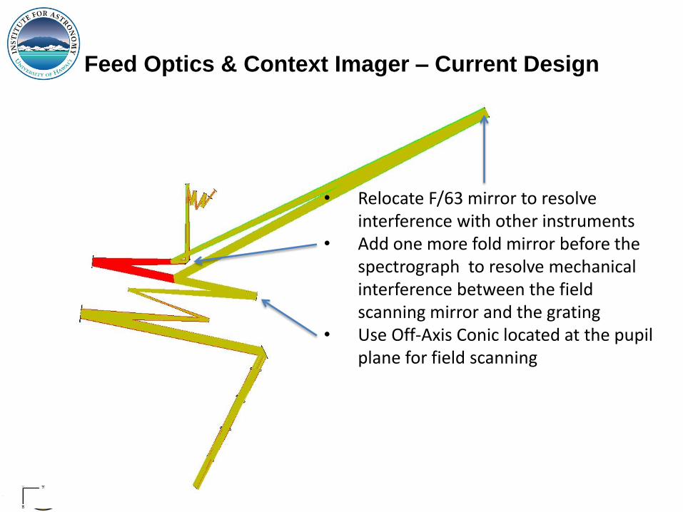
Feed Optics & Context Imager – Current Design
• Relocate F/63 mirror to resolve interference with other instruments
• Add one more fold mirror before the spectrograph to resolve mechanical interference between the field scanning mirror and the grating
• Use Off-Axis Conic located at the pupil plane for field scanning
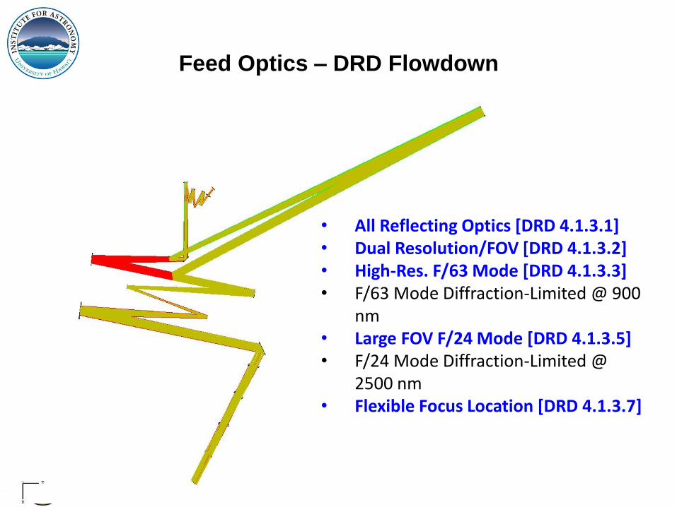
Feed Optics – DRD Flowdown
• All Reflecting Optics [DRD 4.1.3.1] • Dual Resolution/FOV [DRD 4.1.3.2] • High-Res. F/63 Mode [DRD 4.1.3.3] • F/63 Mode Diffraction-Limited @ 900
nm • Large FOV F/24 Mode [DRD 4.1.3.5] • F/24 Mode Diffraction-Limited @
2500 nm • Flexible Focus Location [DRD 4.1.3.7]

DL-NIRSP in Coudé Room
• Last exit on Autobahn…
6/27/2011 84 DL-NIRSP PDR, Tucson, AZ, June 23-24, 2011
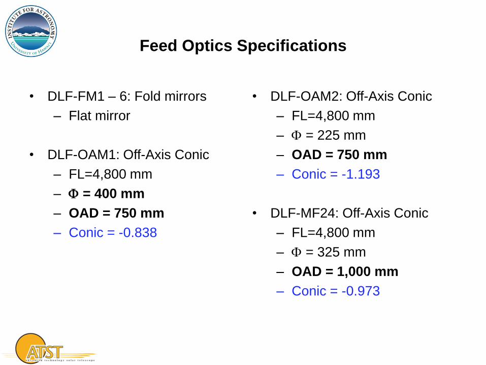
Feed Optics Specifications
• DLF-FM1 – 6: Fold mirrors
– Flat mirror
• DLF-OAM1: Off-Axis Conic
– FL=4,800 mm
– = 400 mm
– OAD = 750 mm
– Conic = -0.838
• DLF-OAM2: Off-Axis Conic
– FL=4,800 mm
– = 225 mm
– OAD = 750 mm
– Conic = -1.193
• DLF-MF24: Off-Axis Conic
– FL=4,800 mm
– = 325 mm
– OAD = 1,000 mm
– Conic = -0.973
F/24
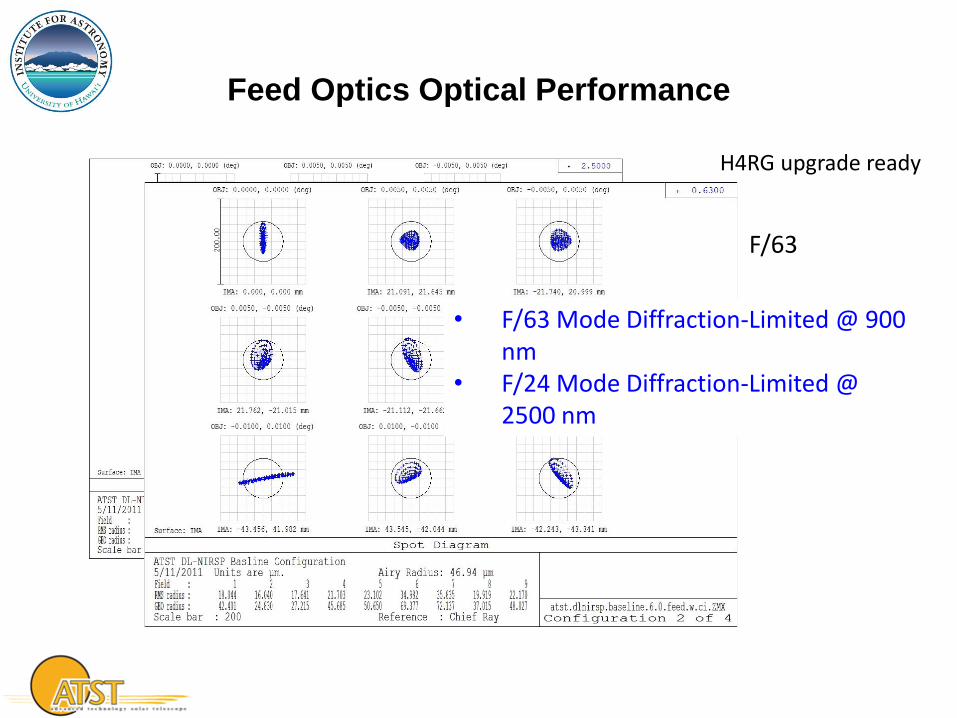
Feed Optics Optical Performance
H4RG upgrade ready
• F/63 Mode Diffraction-Limited @ 900 nm
• F/24 Mode Diffraction-Limited @ 2500 nm
F/63

Design Requirements for Feed Optics
DRD Description Requirements Comp
4.1.3 Feed Optics
4.1.3.
1
Feed Optics Construction All Reflecting Optics Y
4.1.3.
2
Resolution & FOV Coverage Dual Resolution/FOV Y
4.1.3.
3
Feed Optics Feature High-Resolution F/63 Mode Y
4.1.3.
4
F/63 Mode Resolution Diffraction-limited at 900 nm Y
4.1.3.
5
Feed Optics Feature Large-FOV F/24 Mode Y
4.1.3.
6
F/24 Mode Resolution Diffraction-limited at 2500 nm Y
4.1.3.
7
Feed Optics Feature Flexible Feed Optics Focal Plane
Location
Y
6/27/2011 87 DL-NIRSP PDR, Tucson, AZ, June 23-24, 2011
Context Imager
6/27/2011 DL-NIRSP PDR, Tucson, AZ, June 23-24, 2011 88
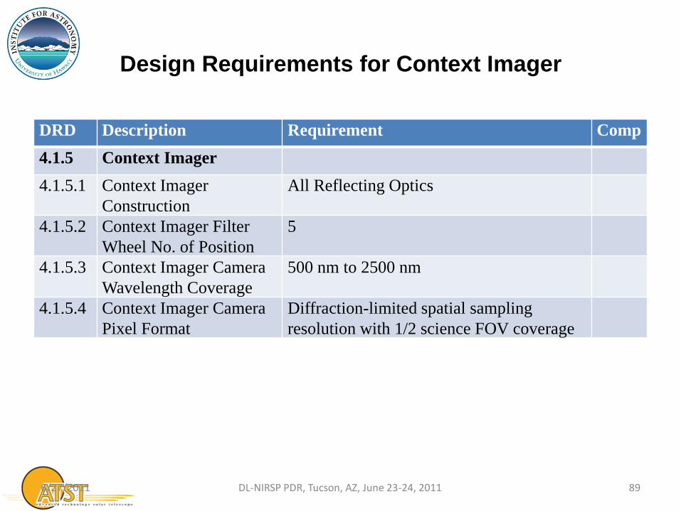
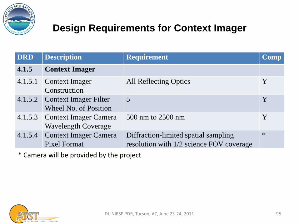
Design Requirements for Context Imager
DRD Description Requirement Comp
4.1.5 Context Imager
4.1.5.1 Context Imager
Construction
All Reflecting Optics
4.1.5.2 Context Imager Filter
Wheel No. of Position
5
4.1.5.3 Context Imager Camera
Wavelength Coverage
500 nm to 2500 nm
4.1.5.4 Context Imager Camera
Pixel Format
Diffraction-limited spatial sampling
resolution with 1/2 science FOV coverage
6/27/2011 89 DL-NIRSP PDR, Tucson, AZ, June 23-24, 2011
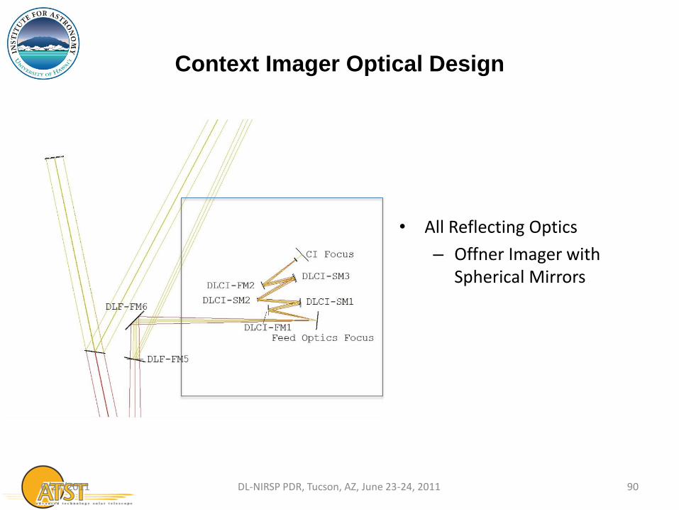
Context Imager Optical Design
6/27/2011 90 DL-NIRSP PDR, Tucson, AZ, June 23-24, 2011
• All Reflecting Optics
– Offner Imager with Spherical Mirrors
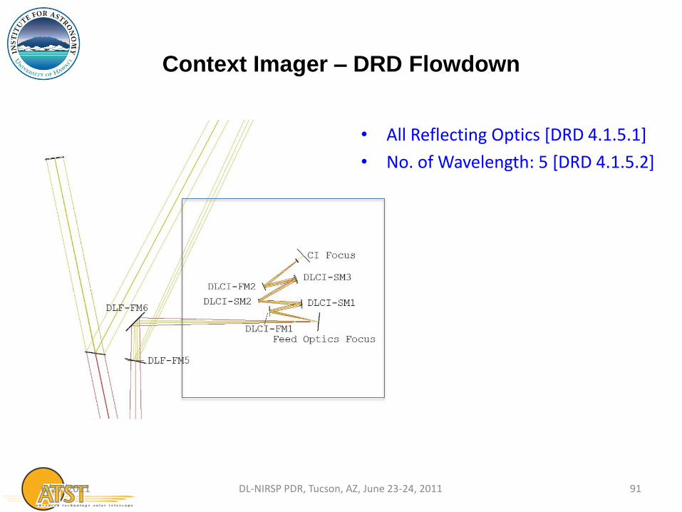
Context Imager – DRD Flowdown
6/27/2011 91 DL-NIRSP PDR, Tucson, AZ, June 23-24, 2011
• All Reflecting Optics [DRD 4.1.5.1]
• No. of Wavelength: 5 [DRD 4.1.5.2]

Context Imager Mechanical Design
6/27/2011 92 DL-NIRSP PDR, Tucson, AZ, June 23-24, 2011
• All Reflecting Optics [DRD 4.1.5.1]
• No. of Wavelength: 5 [DRD 4.1.5.2]
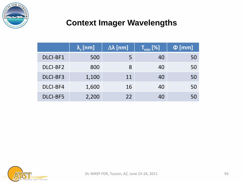
Context Imager Wavelengths
λc [nm] λ [nm] Tmin [%] Φ [mm]
DLCI-BF1 500 5 40 50
DLCI-BF2 800 8 40 50
DLCI-BF3 1,100 11 40 50
DLCI-BF4 1,600 16 40 50
DLCI-BF5 2,200 22 40 50
6/27/2011 93 DL-NIRSP PDR, Tucson, AZ, June 23-24, 2011

F/24
Context Imager Optical Performance
F/63
• Diffraction-limited spatial sampling resolution with 1/2 science FOV coverage [DRD 4.1.5.4]
Design Requirements for Context Imager
DRD Description Requirement Comp
4.1.5 Context Imager
4.1.5.1 Context Imager
Construction
All Reflecting Optics Y
4.1.5.2 Context Imager Filter
Wheel No. of Position
5 Y
4.1.5.3 Context Imager Camera
Wavelength Coverage
500 nm to 2500 nm Y
4.1.5.4 Context Imager Camera
Pixel Format
Diffraction-limited spatial sampling
resolution with 1/2 science FOV coverage
*
6/27/2011 95 DL-NIRSP PDR, Tucson, AZ, June 23-24, 2011
* Camera will be provided by the project

Spectrograph
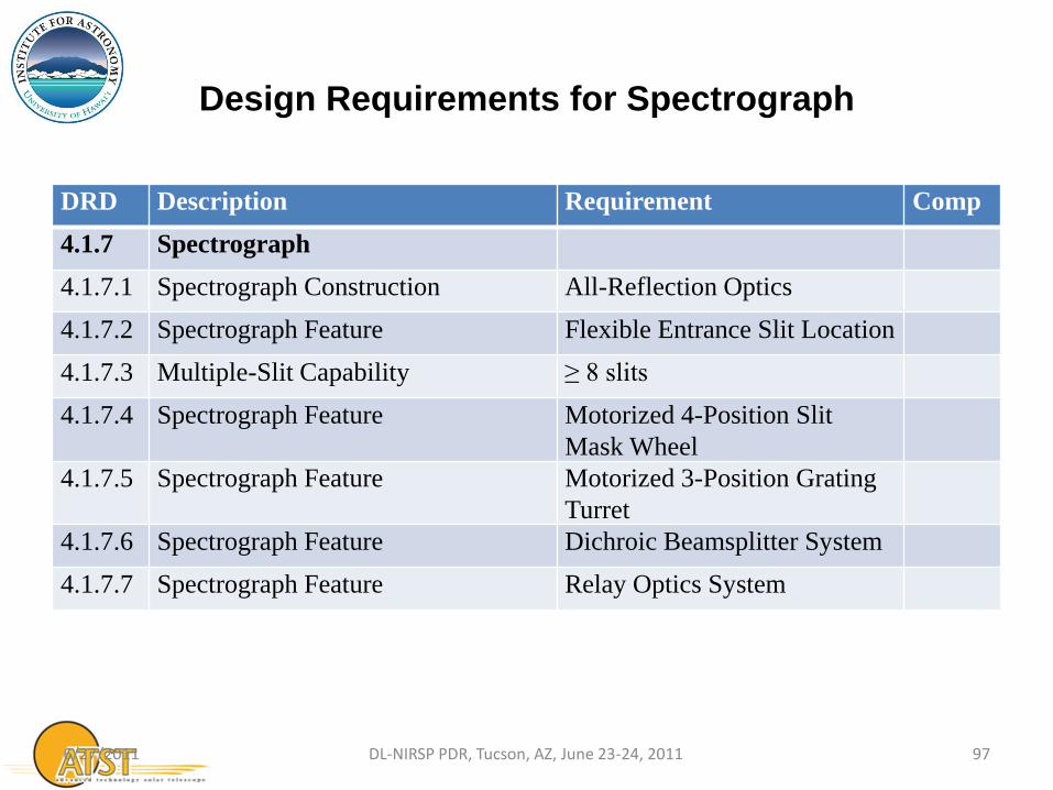
Design Requirements for Spectrograph
DRD Description Requirement Comp
4.1.7 Spectrograph
4.1.7.1 Spectrograph Construction All-Reflection Optics
4.1.7.2 Spectrograph Feature Flexible Entrance Slit Location
4.1.7.3 Multiple-Slit Capability ≥ 8 slits
4.1.7.4 Spectrograph Feature Motorized 4-Position Slit
Mask Wheel
4.1.7.5 Spectrograph Feature Motorized 3-Position Grating
Turret
4.1.7.6 Spectrograph Feature Dichroic Beamsplitter System
4.1.7.7 Spectrograph Feature Relay Optics System
6/27/2011 97 DL-NIRSP PDR, Tucson, AZ, June 23-24, 2011
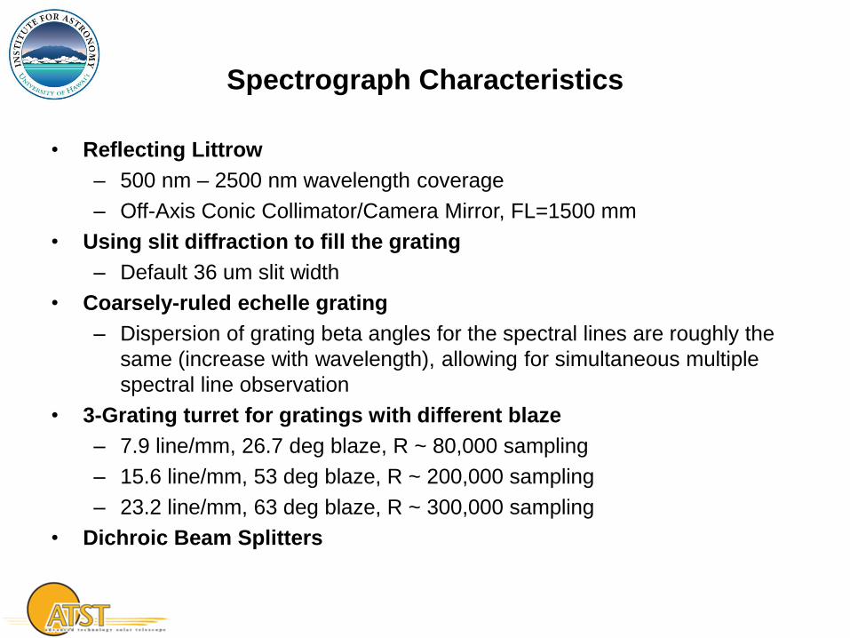
Spectrograph Characteristics
• Reflecting Littrow
– 500 nm – 2500 nm wavelength coverage
– Off-Axis Conic Collimator/Camera Mirror, FL=1500 mm
• Using slit diffraction to fill the grating
– Default 36 um slit width
• Coarsely-ruled echelle grating
– Dispersion of grating beta angles for the spectral lines are roughly the
same (increase with wavelength), allowing for simultaneous multiple
spectral line observation
• 3-Grating turret for gratings with different blaze
– 7.9 line/mm, 26.7 deg blaze, R ~ 80,000 sampling
– 15.6 line/mm, 53 deg blaze, R ~ 200,000 sampling
– 23.2 line/mm, 63 deg blaze, R ~ 300,000 sampling
• Dichroic Beam Splitters
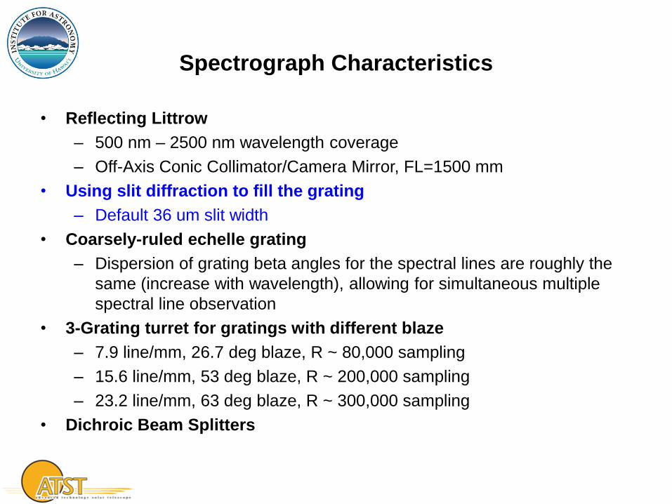
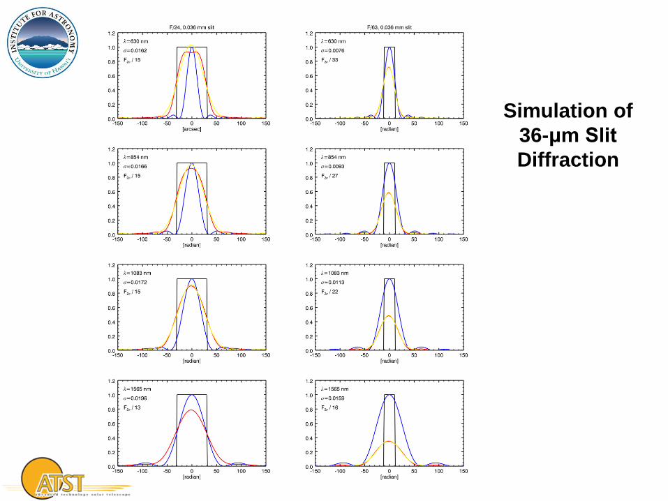
Simulation of
36-μm Slit
Diffraction
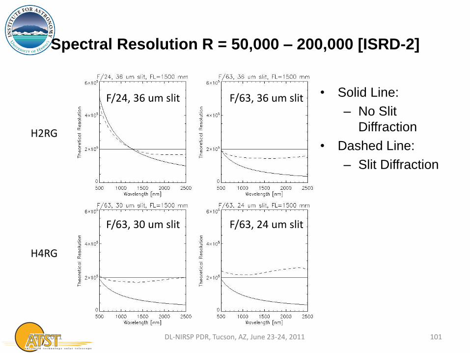
Spectral Resolution R = 50,000 – 200,000 [ISRD-2]
• Solid Line:
– No Slit
Diffraction
• Dashed Line:
– Slit Diffraction
6/27/2011 101 DL-NIRSP PDR, Tucson, AZ, June 23-24, 2011
H4RG
F/63, 30 um slit F/63, 24 um slit
F/63, 36 um slit F/24, 36 um slit
H2RG
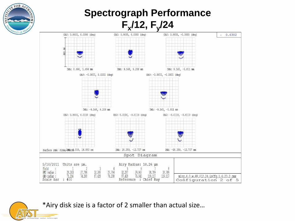
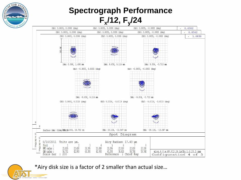
Spectrograph Performance
Fx/12, Fy/24
*Airy disk size is a factor of 2 smaller than actual size…
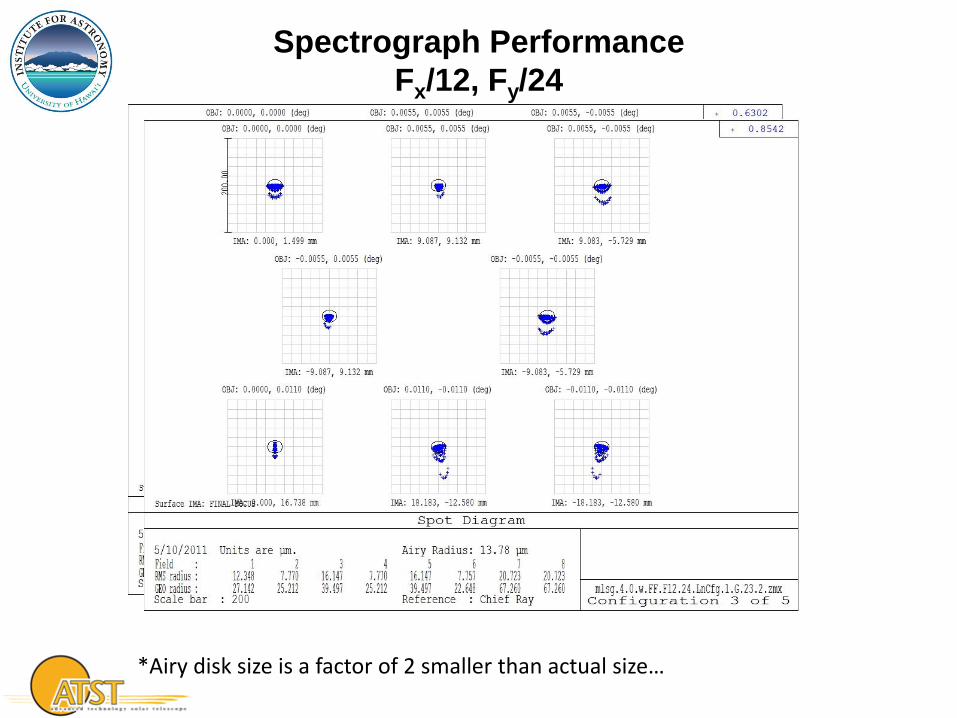
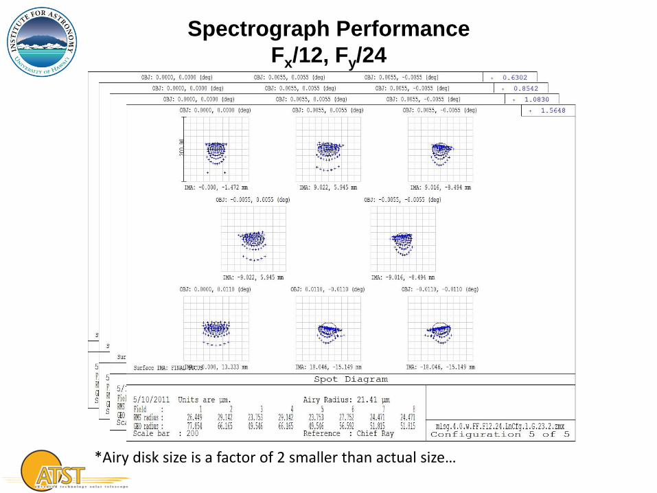
Spectrograph Performance
Fx/12, Fy/24
*Airy disk size is a factor of 2 smaller than actual size…
Spectrograph Performance
Fx/12, Fy/24
*Airy disk size is a factor of 2 smaller than actual size…
Spectrograph Performance
Fx/12, Fy/24
*Airy disk size is a factor of 2 smaller than actual size…

Coarsely-Ruled Gratings
• Wavelength Range 500 nm – 2500 nm [ISRD-1]
⇒ All-Reflecting Spectrograph [DRD 4.1.7.1]
⇒Off-Axis Reflecting Littrow Spectrograph
The image quality of off-axis reflecting Littrow degrades very quickly as the location of the exit slit moves away from the position that is symmetric to the entrance slit around the chief ray of the on-axis focal point of the parent parabola.
• Simultaneous 4 wavelengths [ISRD-10] + Reflecting Littrow
⇒ Coarsely-Ruled Grating
Given a fixe grating α, the exit slits of all the wavelengths emerge within a small range in grating β, making it possible to maintain good image quality for all the wavelengths.
⇒ Dichroic Beam Splitters [DRD 4.1.7.6]
6/27/2011 106 DL-NIRSP PDR, Tucson, AZ, June 23-24, 2011

6/27/2011 107 DL-NIRSP PDR, Tucson, AZ, June 23-24, 2011

Spectrograph Optical Design
Dec. 2010
Context Imager
Spectrograph
Feed Optics Field Scanning Mirror
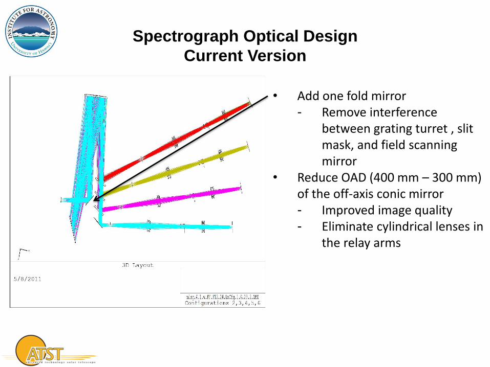
Spectrograph Optical Design
Current Version
• Add one fold mirror - Remove interference
between grating turret , slit mask, and field scanning mirror
• Reduce OAD (400 mm – 300 mm) of the off-axis conic mirror - Improved image quality - Eliminate cylindrical lenses in
the relay arms

Slit Mask
Grating
Off-Axis Conic, Collimator, Camera Mirror
Fold Mirror
Dichoric Beamsplitters
Air-spaced Doublet Relay Collimator
Wollaston DWDM Filter
Liquid Crystal x 2 (not shown)
Final Focus, FPA Int. Focus Spectral Field Mask
Air-spaced Doublet Relay Camera Lens
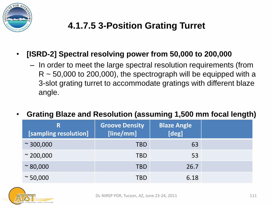
4.1.7.5 3-Position Grating Turret
• [ISRD-2] Spectral resolving power from 50,000 to 200,000
– In order to meet the large spectral resolution requirements (from
R ~ 50,000 to 200,000), the spectrograph will be equipped with a
3-slot grating turret to accommodate gratings with different blaze
angle.
• Grating Blaze and Resolution (assuming 1,500 mm focal length)
R [sampling resolution]
Groove Density [line/mm]
Blaze Angle [deg]
~ 300,000 TBD 63
~ 200,000 TBD 53
~ 80,000 TBD 26.7
~ 50,000 TBD 6.18
6/27/2011 111 DL-NIRSP PDR, Tucson, AZ, June 23-24, 2011
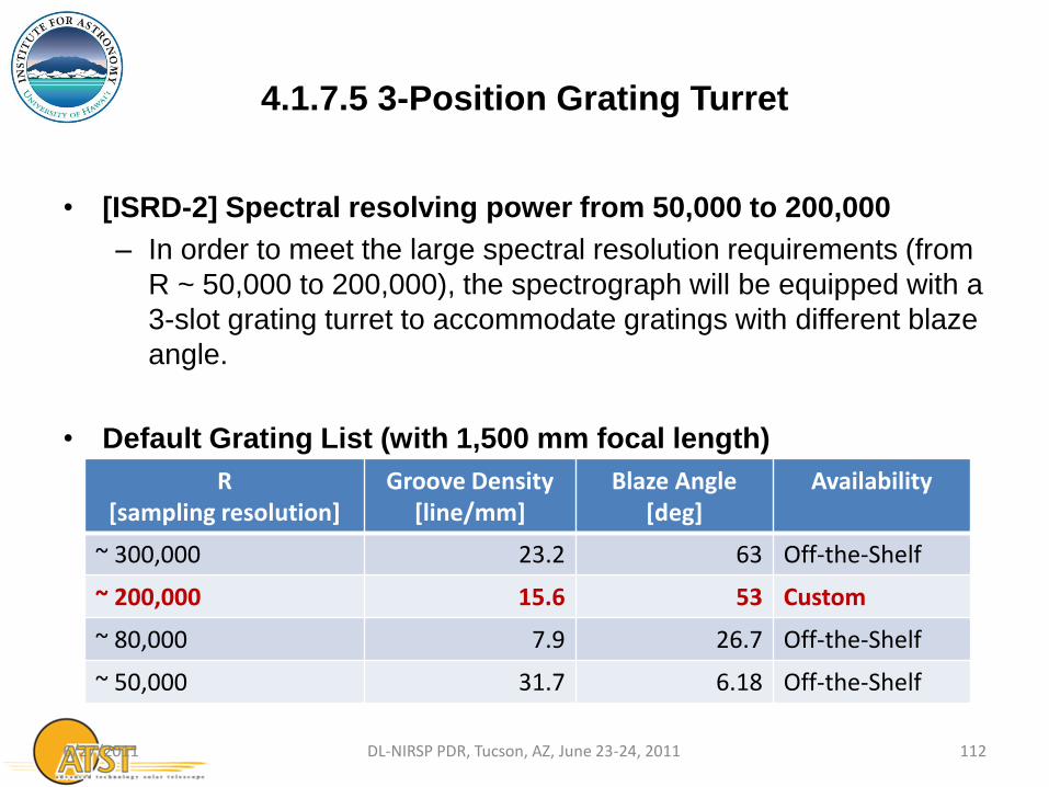
4.1.7.5 3-Position Grating Turret
• [ISRD-2] Spectral resolving power from 50,000 to 200,000
– In order to meet the large spectral resolution requirements (from
R ~ 50,000 to 200,000), the spectrograph will be equipped with a
3-slot grating turret to accommodate gratings with different blaze
angle.
• Default Grating List (with 1,500 mm focal length)
R [sampling resolution]
Groove Density [line/mm]
Blaze Angle [deg]
Availability
~ 300,000 23.2 63 Off-the-Shelf
~ 200,000 15.6 53 Custom
~ 80,000 7.9 26.7 Off-the-Shelf
~ 50,000 31.7 6.18 Off-the-Shelf
6/27/2011 112 DL-NIRSP PDR, Tucson, AZ, June 23-24, 2011
Grating Efficiency
• Coarsely-Ruled echelle gratings operate at high order for the
spectral lines within the working range of the spectrograph.
• Small variation of grating βs for a fixed grating α for the spectral
lines
⇒ High diffraction efficiency for most of the lines…
6/27/2011 113 DL-NIRSP PDR, Tucson, AZ, June 23-24, 2011

6/27/2011 114 DL-NIRSP PDR, Tucson, AZ, June 23-24, 2011
Why R = 200,000 with Custom 15.6 line/mm,
53 deg blaze grating?
• Increased number of slits
– Better system efficiency
• Relaxed DWDM filter specification
– broader bandpass
– Lower filter cost
– An important design goal of DL-NIRSP is to achieve high system
efficiency to improve the temporal resolution of the observation,
which is critical for the study of the dynamic of solar magnetism.
6/27/2011 115 DL-NIRSP PDR, Tucson, AZ, June 23-24, 2011

Relay Optics
• 1:1 relay with fl=400 mm air-spaced doublet
• Spectral Field Masks at spectrograph focus
– Relaxed DWDM filter bandwidth specification
• Intermediate pupil plane available for
– DWDM Bandpass Isolation Filter
– Polarization Modulators (Liquid Crystal Variable Retarders)
– Wollaston Polarizing Beamsplitter
– Reduce size requirement for optics
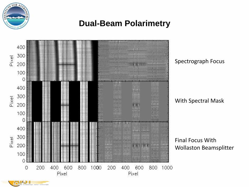
Dual-Beam Polarimetry
Spectrograph Focus
With Spectral Mask
Final Focus With Wollaston Beamsplitter

Design Requirements for Spectrograph
DRD Description Requirement Comp
4.1.7 Spectrograph
4.1.7.1 Spectrograph Construction All-Reflection Optics Y
4.1.7.2 Spectrograph Feature Flexible Entrance Slit Location
4.1.7.3 Multiple-Slit Capability ≥ 8 slits ?
4.1.7.4 Spectrograph Feature Motorized 4-Position Slit
Mask Wheel
4.1.7.5 Spectrograph Feature Motorized 3-Position Grating
Turret
4.1.7.6 Spectrograph Feature Dichroic Beamsplitter System Y
4.1.7.7 Spectrograph Feature Relay Optics System Y
6/27/2011 118 DL-NIRSP PDR, Tucson, AZ, June 23-24, 2011
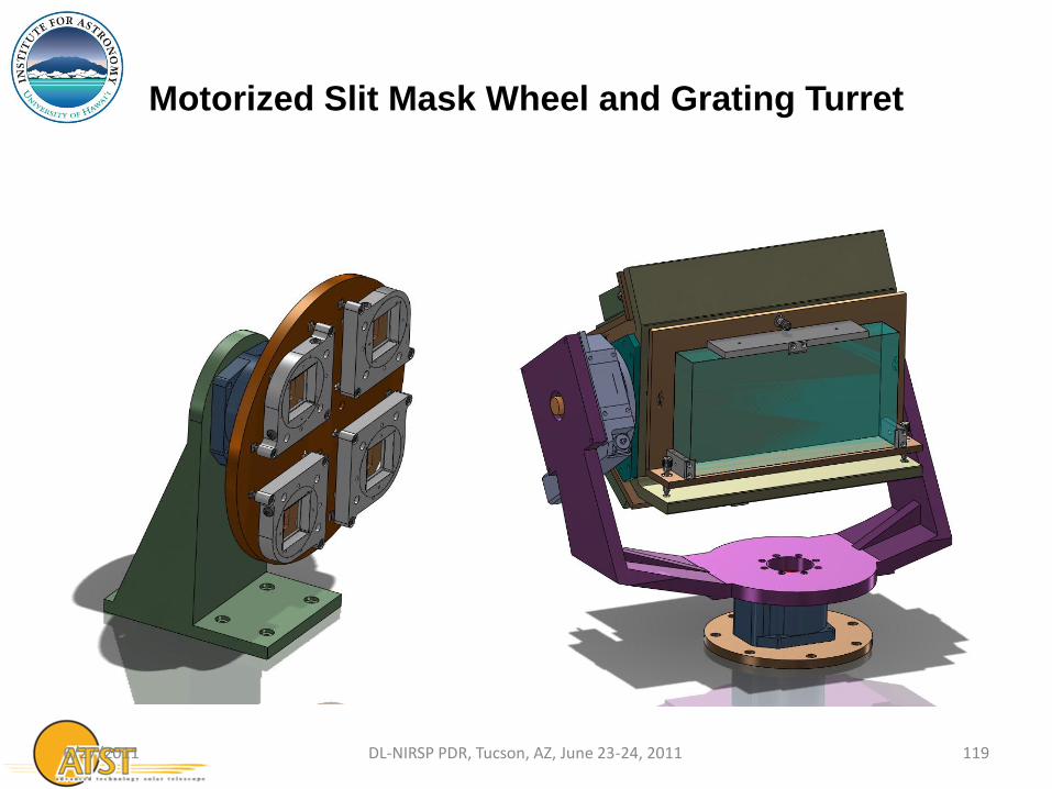
Motorized Slit Mask Wheel and Grating Turret
6/27/2011 119 DL-NIRSP PDR, Tucson, AZ, June 23-24, 2011

Flexible Entrance Slit Location
Scanning Long-Slit Spectrograph Mode
6/27/2011 120 DL-NIRSP PDR, Tucson, AZ, June 23-24, 2011
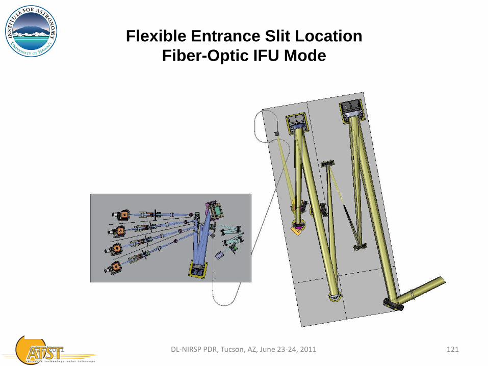
Flexible Entrance Slit Location
Fiber-Optic IFU Mode
6/27/2011 121 DL-NIRSP PDR, Tucson, AZ, June 23-24, 2011
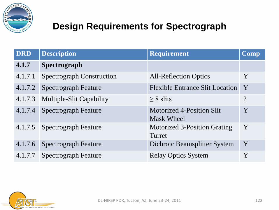
Design Requirements for Spectrograph
DRD Description Requirement Comp
4.1.7 Spectrograph
4.1.7.1 Spectrograph Construction All-Reflection Optics Y
4.1.7.2 Spectrograph Feature Flexible Entrance Slit Location Y
4.1.7.3 Multiple-Slit Capability ≥ 8 slits ?
4.1.7.4 Spectrograph Feature Motorized 4-Position Slit
Mask Wheel
Y
4.1.7.5 Spectrograph Feature Motorized 3-Position Grating
Turret
Y
4.1.7.6 Spectrograph Feature Dichroic Beamsplitter System Y
4.1.7.7 Spectrograph Feature Relay Optics System Y
6/27/2011 122 DL-NIRSP PDR, Tucson, AZ, June 23-24, 2011

Fiber-Optic IFU
for Coronal Magnetometry
6/27/2011 DL-NIRSP PDR, Tucson, AZ, June 23-24, 2011 123

Design Challenges of Coronal Magnetometry
• One of the promises of the 4-m aperture of the ATST is to deliver
high photon flux required by coronal magnetometry
• From 0.4-m Evans Coronagraph to 4-m ATST is real nice, but…
– Focal Plane Array pixel size does not increase by 10x…
– Focal plane array chip size does not increase by 10X…
– Grating size does not increase by 10X…
– F/# of optics wants to stay the same…
⇒ It is very difficult to do low spatial resolution, large FOV
observation with large telescope!
6/27/2011 124 DL-NIRSP PDR, Tucson, AZ, June 23-24, 2011
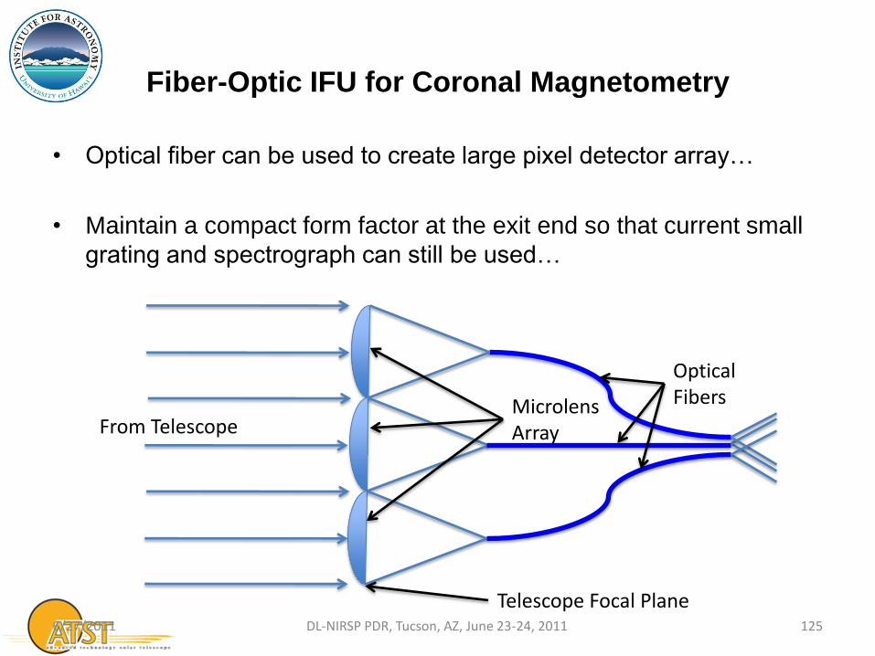
Fiber-Optic IFU for Coronal Magnetometry
• Optical fiber can be used to create large pixel detector array…
• Maintain a compact form factor at the exit end so that current small
grating and spectrograph can still be used…
6/27/2011 125 DL-NIRSP PDR, Tucson, AZ, June 23-24, 2011
Microlens Array
Optical Fibers
From Telescope
Telescope Focal Plane
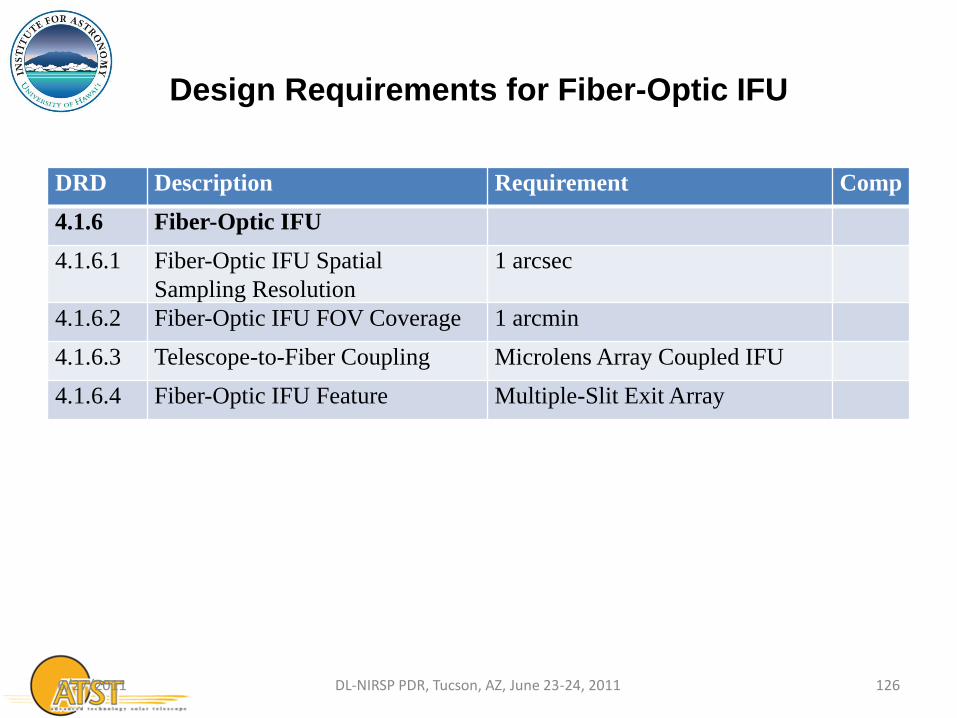
Design Requirements for Fiber-Optic IFU
DRD Description Requirement Comp
4.1.6 Fiber-Optic IFU
4.1.6.1 Fiber-Optic IFU Spatial
Sampling Resolution
1 arcsec
4.1.6.2 Fiber-Optic IFU FOV Coverage 1 arcmin
4.1.6.3 Telescope-to-Fiber Coupling Microlens Array Coupled IFU
4.1.6.4 Fiber-Optic IFU Feature Multiple-Slit Exit Array
6/27/2011 126 DL-NIRSP PDR, Tucson, AZ, June 23-24, 2011
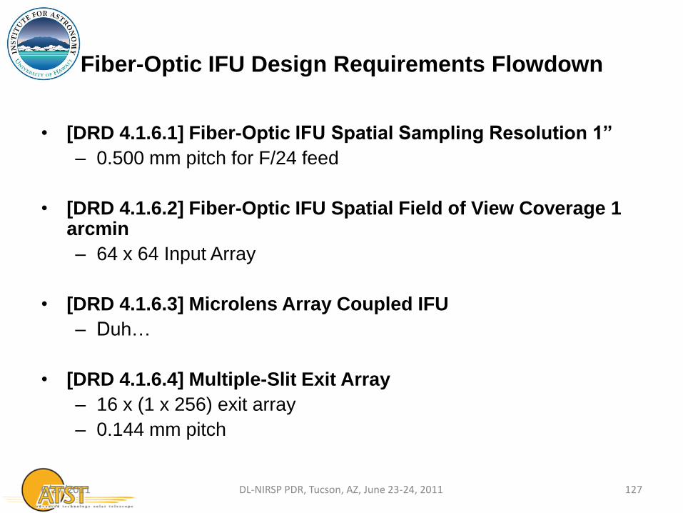
Fiber-Optic IFU Design Requirements Flowdown
• [DRD 4.1.6.1] Fiber-Optic IFU Spatial Sampling Resolution 1”
– 0.500 mm pitch for F/24 feed
• [DRD 4.1.6.2] Fiber-Optic IFU Spatial Field of View Coverage 1 arcmin
– 64 x 64 Input Array
• [DRD 4.1.6.3] Microlens Array Coupled IFU
– Duh…
• [DRD 4.1.6.4] Multiple-Slit Exit Array
– 16 x (1 x 256) exit array
– 0.144 mm pitch
6/27/2011 127 DL-NIRSP PDR, Tucson, AZ, June 23-24, 2011

Coronal Fiber-Optic IFU with F/24 Feed
6/27/2011 128 DL-NIRSP PDR, Tucson, AZ, June 23-24, 2011

Design Requirements for Fiber-Optic IFU
DRD Description Requirement Comp
4.1.6 Fiber-Optic IFU
4.1.6.1 Fiber-Optic IFU Spatial
Sampling Resolution
1 arcsec Y
4.1.6.2 Fiber-Optic IFU FOV Coverage 1 arcmin Y
4.1.6.3 Telescope-to-Fiber Coupling Microlens Array Coupled IFU Y
4.1.6.4 Fiber-Optic IFU Feature Multiple-Slit Exit Array Y
6/27/2011 129 DL-NIRSP PDR, Tucson, AZ, June 23-24, 2011
Polarimetry
6/27/2011 DL-NIRSP PDR, Tucson, AZ, June 23-24, 2011 130

Polarimetry
• Polarization measurements of all ATST instruments are strongly
coupled to the telescope polarization property…
– Close collaboration with ATST Project is needed to achieve the
polarization accuracy required for the science…
6/27/2011 131 DL-NIRSP PDR, Tucson, AZ, June 23-24, 2011
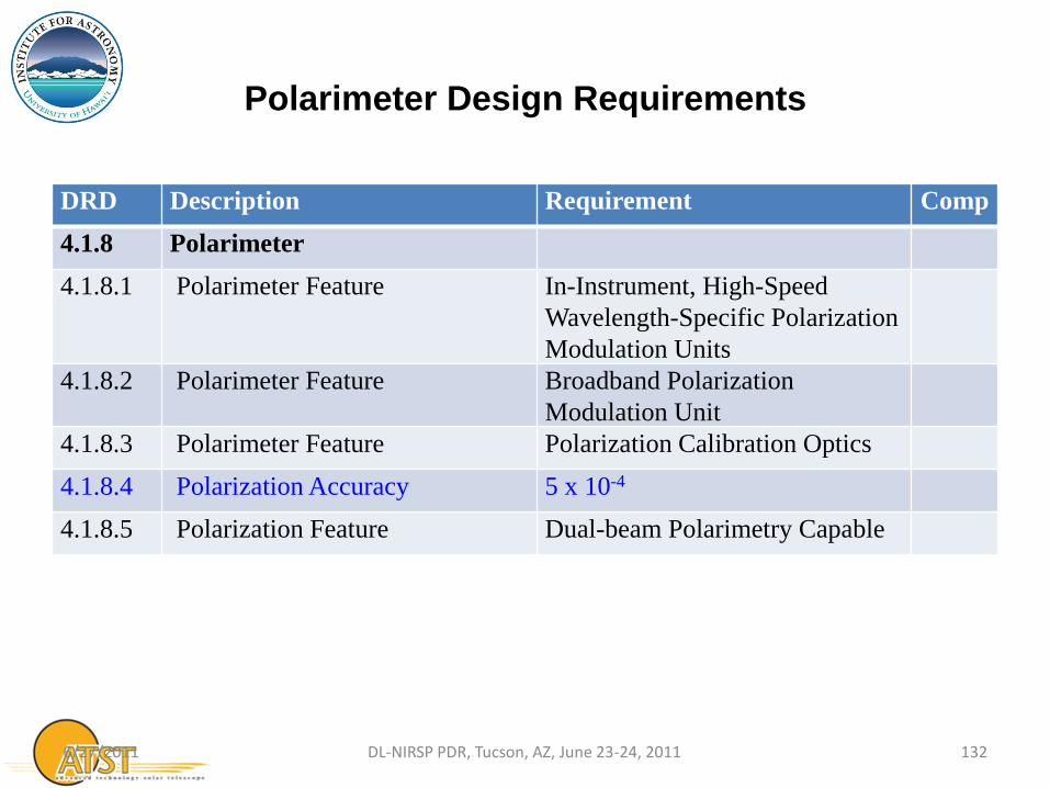
Polarimeter Design Requirements
DRD Description Requirement Comp
4.1.8 Polarimeter
4.1.8.1 Polarimeter Feature In-Instrument, High-Speed
Wavelength-Specific Polarization
Modulation Units
4.1.8.2 Polarimeter Feature Broadband Polarization
Modulation Unit
4.1.8.3 Polarimeter Feature Polarization Calibration Optics
4.1.8.4 Polarization Accuracy 5 x 10⁻⁴
4.1.8.5 Polarization Feature Dual-beam Polarimetry Capable
6/27/2011 132 DL-NIRSP PDR, Tucson, AZ, June 23-24, 2011

Polarimeter Requirements Flowdown
• [DRD 4.1.8.1] In-Instrument, High-Speed Wavelength-Specific Polarization Modulation Units – Default Meadowlark SWIFT dual-LCVR Modulator for each relay arm
• [DRD 4.1.8.2] Broadband Polarization Modulation Unit
– Utilize facility GOS modulator for coronal IFU
• [DRD 4.1.8.3] Polarization Calibration Optics – Utilize facility GOS polarization calibration optics
• [DRD 4.1.8.4] Polarization Accuracy 5 x 10⁻⁴
– Working with Project Instrument Scientist…
• [DRD 4.1.8.5] Dual-beam Polarimetry Capable – Designed-In for scanning long-slit mode – Need additional Wollaston beamsplitter before fiber-optic IFU – Decreased fiber-optic IFU FOV coverage (60” x 30”)
6/27/2011 133 DL-NIRSP PDR, Tucson, AZ, June 23-24, 2011
Fiber-Optic IFU Mosaic
6/27/2011 134 DL-NIRSP PDR, Tucson, AZ, June 23-24, 2011
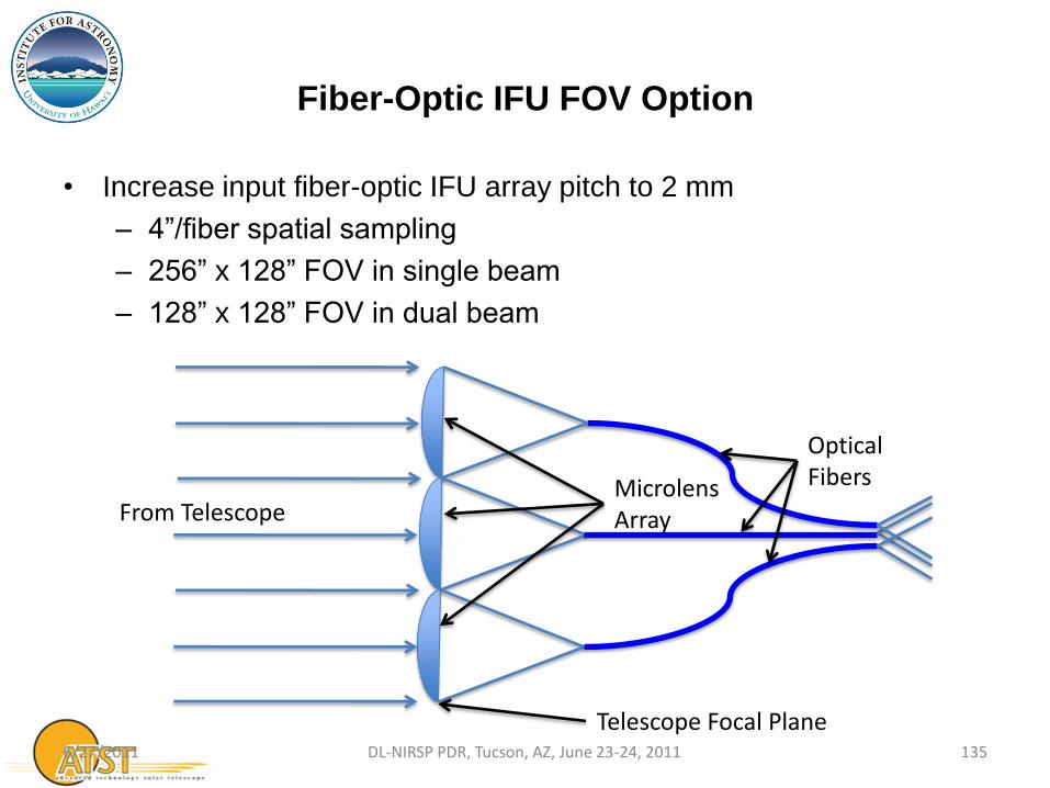
Fiber-Optic IFU FOV Option
• Increase input fiber-optic IFU array pitch to 2 mm
– 4”/fiber spatial sampling
– 256” x 128” FOV in single beam
– 128” x 128” FOV in dual beam
6/27/2011 135 DL-NIRSP PDR, Tucson, AZ, June 23-24, 2011
Microlens Array
Optical Fibers
From Telescope
Telescope Focal Plane

Polarimeter Design Requirements Compliance
DRD Description Requirement Comp
4.1.8 Polarimeter
4.1.8.1 Polarimeter Feature In-Instrument, High-Speed
Wavelength-Specific Polarization
Modulation Units
Y
4.1.8.2 Polarimeter Feature Broadband Polarization
Modulation Unit
Y
4.1.8.3 Polarimeter Feature Polarization Calibration Optics Y
4.1.8.4 Polarization Accuracy 5 x 10-4 Y*
4.1.8.5 Polarization Feature Dual-beam Polarimetry Capable Y
6/27/2011 136 DL-NIRSP PDR, Tucson, AZ, June 23-24, 2011
*Project activities…