
*KURAに登録されているコンテンツの著作権は,執筆者,出版社(学協会)などが有します。*KURAに登録されているコンテンツの利用については,著作権法に規定されている私的使用や引用などの範囲内で行ってください。*著作権法に規定されている私的使用や引用などの範囲を超える利用を行う場合には,著作権者の許諾を得てください。ただし,著作権者から著作権等管理事業者(学術著作権協会,日本著作出版権管理システムなど)に権利委託されているコンテンツの利用手続については,各著作権等管理事業者に確認してください。
Title Tip-sample distance control using photothermal actuation of a smallcantilever for high-speed atomic force microscopy
Author(s) Yamashita, Hayato; Kodera, Noriyuki; Miyagi, Atsushi; Uchihashi,Takayuki; Yamamoto, Daisuke; Ando, Toshio
Citation Review of Scientific Instruments, 78(8): 83702-83706
Issue Date 2007
Type Journal Article
Text version publisher
URL http://hdl.handle.net/2297/11929
Right
http://dspace.lib.kanazawa-u.ac.jp/dspace/

Tip-sample distance control using photothermal actuation of a smallcantilever for high-speed atomic force microscopy
Hayato Yamashita,a� Noriyuki Kodera, and Atsushi MiyagiDepartment of Physics, Kanazawa University, Kakuma-machi, Kanazawa 920-1192, Japan
Takayuki Uchihashi, Daisuke Yamamoto, and Toshio AndoDepartment of Physics, Kanazawa University, Kakuma-machi, Kanazawa 920-1192, Japan and CREST, JST,4-1-8 Honcho Kawaguchi, Saitama 332-0012, Japan
�Received 12 April 2007; accepted 2 July 2007; published online 10 August 2007�
We have applied photothermal bending of a cantilever induced by an intensity-modulated infraredlaser to control the tip-surface distance in atomic force microscopy. The slow response of thephotothermal expansion effect is eliminated by inverse transfer function compensation. Byregulating the laser power and regulating the cantilever deflection, the tip-sample distance iscontrolled; this enables much faster imaging than that in the conventional piezoactuator-based zscanners because of the considerably higher resonant frequency of small cantilevers. Using thiscontrol together with other devices optimized for high-speed scanning, video-rate imaging of proteinmolecules in liquids is achieved. © 2007 American Institute of Physics. �DOI: 10.1063/1.2766825�
I. INTRODUCTION
Atomic force microscopy �AFM� has the unique capabil-ity to image biomolecules under physiological conditions ata high spatial resolution.1,2 If the imaging rate of the AFM isenhanced significantly, this unique capability will becomemore useful in biological sciences because it enables us topractically observe the dynamic behavior of biological mac-romolecules. Therefore, various efforts have been made toincrease the scan speed.3–11 In addition, some efforts havebeen made to reduce the tip-sample interaction force withoutreducing the scan speed in the tapping mode.10 Owing tothese efforts, the feedback bandwidth has increased to ap-proximately 70 kHz, thereby enabling the capture of movingprotein molecules on video at �48 ms/frame for a scanrange of �240 nm without damaging them.8,10
To widen the scope of biological systems whose dy-namic behaviors can be studied by high-speed AFM, effortstoward further enhancement of the imaging rate are required.Among the various modes, tapping mode operates most gen-tly on biological samples. This is because, in this mode, theoscillating tip exerts very small lateral forces onto the sampleas long as the feedback bandwidth is sufficiently high tofacilitate the tip to accurately trace the sample topography.12
However, the feedback bandwidth is limited by various fac-tors. The slowest device in the feedback loop is the z scannerbecause the capacity of the available piezoactuators is lim-ited. The response speed of the z scanner is approximatelyexpressed by �fs /Qs, where Qs and fs are the quality factorand resonant frequency of the z scanner, respectively. Al-though Qs can be reduced to 0.5 by an active dampingtechnique,8 fs is almost determined by the required maxi-mum displacement and hardly exceeds �200 kHz in prac-tice.
In order to overcome this problem, instead of a conven-tional piezoactuator-based z scanner, a cantilever deflectioncan be used to control the tip-sample distance because it iseasier to increase the resonant frequency of the cantileverthan that of the piezoelectric actuator. One possible tech-nique is the magnetic actuation of a cantilever.13 However,when the cantilever is coated with a magnetic material, itsresonant frequency reduces and it also becomes stiff, whichis inappropriate for high-speed imaging on biologicalsamples. Another possible technique is to actuate the canti-lever by laser illumination onto the cantilever. There are sev-eral reports in which an intensity-modulated laser beam isirradiated onto a cantilever for actuation.14–17 This actuationis based either on the irradiation pressure or on the photo-thermal expansion with gold-coated cantilevers.15 In liquids,the latter effect is dominant because of the low quality factorof cantilevers. Although some studies have employed thephotothermal effect for exciting resonant vibrations in canti-levers, this effect has never been used in controlling the tip-sample distance. This is because of the slow response of thephotothermal bending of cantilevers due to the slow heattransmission.16 In this study, we have solved this problem byusing an inverse transfer function compensation.
II. EXPERIMENTS
A. Apparatus
The in-house developed high-speed AFM apparatus usedin this study is basically the same as that reportedpreviously.4 The optical beam deflection method optimizedfor small cantilevers was used. In order to detect the canti-lever deflection and drive the cantilever simultaneously, weimplemented a 980 nm IR laser as well as a 675 nm redlaser, as shown in Fig. 1. Beams from the red and IR laserswere introduced into a �20 objective lens and focused ontoa small cantilever with a length of 6–7 �m, width of 2 �m,a�Electronic mail: [email protected]
REVIEW OF SCIENTIFIC INSTRUMENTS 78, 083702 �2007�
0034-6748/2007/78�8�/083702/5/$23.00 © 2007 American Institute of Physics78, 083702-1
Downloaded 16 Aug 2007 to 133.1.87.111. Redistribution subject to AIP license or copyright, see http://rsi.aip.org/rsi/copyright.jsp
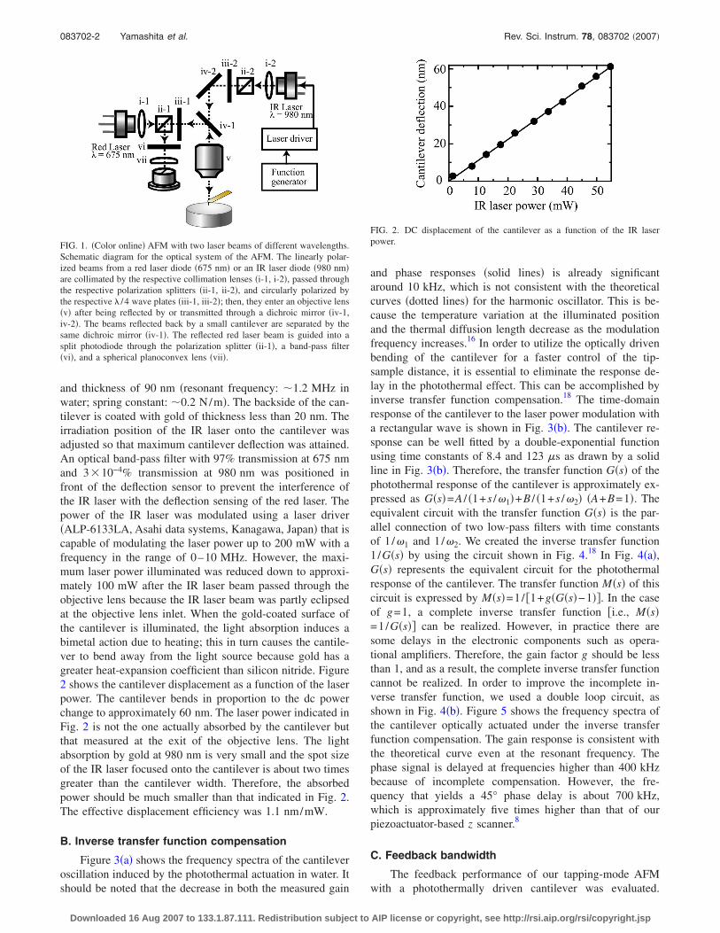
and thickness of 90 nm �resonant frequency: �1.2 MHz inwater; spring constant: �0.2 N/m�. The backside of the can-tilever is coated with gold of thickness less than 20 nm. Theirradiation position of the IR laser onto the cantilever wasadjusted so that maximum cantilever deflection was attained.An optical band-pass filter with 97% transmission at 675 nmand 3�10−4% transmission at 980 nm was positioned infront of the deflection sensor to prevent the interference ofthe IR laser with the deflection sensing of the red laser. Thepower of the IR laser was modulated using a laser driver�ALP-6133LA, Asahi data systems, Kanagawa, Japan� that iscapable of modulating the laser power up to 200 mW with afrequency in the range of 0–10 MHz. However, the maxi-mum laser power illuminated was reduced down to approxi-mately 100 mW after the IR laser beam passed through theobjective lens because the IR laser beam was partly eclipsedat the objective lens inlet. When the gold-coated surface ofthe cantilever is illuminated, the light absorption induces abimetal action due to heating; this in turn causes the cantile-ver to bend away from the light source because gold has agreater heat-expansion coefficient than silicon nitride. Figure2 shows the cantilever displacement as a function of the laserpower. The cantilever bends in proportion to the dc powerchange to approximately 60 nm. The laser power indicated inFig. 2 is not the one actually absorbed by the cantilever butthat measured at the exit of the objective lens. The lightabsorption by gold at 980 nm is very small and the spot sizeof the IR laser focused onto the cantilever is about two timesgreater than the cantilever width. Therefore, the absorbedpower should be much smaller than that indicated in Fig. 2.The effective displacement efficiency was 1.1 nm/mW.
B. Inverse transfer function compensation
Figure 3�a� shows the frequency spectra of the cantileveroscillation induced by the photothermal actuation in water. Itshould be noted that the decrease in both the measured gain
and phase responses �solid lines� is already significantaround 10 kHz, which is not consistent with the theoreticalcurves �dotted lines� for the harmonic oscillator. This is be-cause the temperature variation at the illuminated positionand the thermal diffusion length decrease as the modulationfrequency increases.16 In order to utilize the optically drivenbending of the cantilever for a faster control of the tip-sample distance, it is essential to eliminate the response de-lay in the photothermal effect. This can be accomplished byinverse transfer function compensation.18 The time-domainresponse of the cantilever to the laser power modulation witha rectangular wave is shown in Fig. 3�b�. The cantilever re-sponse can be well fitted by a double-exponential functionusing time constants of 8.4 and 123 �s as drawn by a solidline in Fig. 3�b�. Therefore, the transfer function G�s� of thephotothermal response of the cantilever is approximately ex-pressed as G�s�=A / �1+s /�1�+B / �1+s /�2� �A+B=1�. Theequivalent circuit with the transfer function G�s� is the par-allel connection of two low-pass filters with time constantsof 1 /�1 and 1/�2. We created the inverse transfer function1/G�s� by using the circuit shown in Fig. 4.18 In Fig. 4�a�,G�s� represents the equivalent circuit for the photothermalresponse of the cantilever. The transfer function M�s� of thiscircuit is expressed by M�s�=1/ �1+g�G�s�−1��. In the caseof g=1, a complete inverse transfer function �i.e., M�s�=1/G�s�� can be realized. However, in practice there aresome delays in the electronic components such as opera-tional amplifiers. Therefore, the gain factor g should be lessthan 1, and as a result, the complete inverse transfer functioncannot be realized. In order to improve the incomplete in-verse transfer function, we used a double loop circuit, asshown in Fig. 4�b�. Figure 5 shows the frequency spectra ofthe cantilever optically actuated under the inverse transferfunction compensation. The gain response is consistent withthe theoretical curve even at the resonant frequency. Thephase signal is delayed at frequencies higher than 400 kHzbecause of incomplete compensation. However, the fre-quency that yields a 45° phase delay is about 700 kHz,which is approximately five times higher than that of ourpiezoactuator-based z scanner.8
C. Feedback bandwidth
The feedback performance of our tapping-mode AFMwith a photothermally driven cantilever was evaluated.
FIG. 1. �Color online� AFM with two laser beams of different wavelengths.Schematic diagram for the optical system of the AFM. The linearly polar-ized beams from a red laser diode �675 nm� or an IR laser diode �980 nm�are collimated by the respective collimation lenses �i-1, i-2�, passed throughthe respective polarization splitters �ii-1, ii-2�, and circularly polarized bythe respective � /4 wave plates �iii-1, iii-2�; then, they enter an objective lens�v� after being reflected by or transmitted through a dichroic mirror �iv-1,iv-2�. The beams reflected back by a small cantilever are separated by thesame dichroic mirror �iv-1�. The reflected red laser beam is guided into asplit photodiode through the polarization splitter �ii-1�, a band-pass filter�vi�, and a spherical planoconvex lens �vii�.
FIG. 2. DC displacement of the cantilever as a function of the IR laserpower.
083702-2 Yamashita et al. Rev. Sci. Instrum. 78, 083702 �2007�
Downloaded 16 Aug 2007 to 133.1.87.111. Redistribution subject to AIP license or copyright, see http://rsi.aip.org/rsi/copyright.jsp

Herein, a small cantilever was oscillated using a piezoactua-tor at its resonant frequency of 1.2 MHz in water �Q=3�,with a free oscillation amplitude of 5 nm. The tip was inter-mittently contacted with a mica surface in water, with anaverage amplitude of 3 nm. The cantilever deflection wasmodulated by sinusoidal signals, and the output signals fromthe proportional-integral-differential �PID� circuit weremonitored for the closed loop. Here, the modulation frequen-cies are much lower than the cantilever resonant frequency.The parameters of the PID controller were adjusted to
achieve the best feedback condition. Figure 6 shows aclosed-loop transfer function with the cantilever actuation.The feedback bandwidth, which is defined as the frequencythat yields 45° phase delay, was approximately 100 kHz asindicated in Fig. 6 �dotted line�. This value is higher by afactor of 1.4 in comparison to the tip-sample distance controlby our piezoactuator-based z scanner.8 Here, although thegain response shows peaks around 100 and 500 kHz, thegain values at the peaks are less than 3 dB, which is the
FIG. 3. �Color online� �a� Frequency spectra of the gain �upper� and phase�lower� for a small cantilever excited by the intensity-modulated IR laser�solid lines� and theoretical frequency spectra for harmonic oscillation �dot-ted lines�. The cantilever amplitude was 10nmp-p. �b� The time-domainresponse of the cantilever displacement driven by the laser modulatedwith a rectangular wave. The response shown with dots is fitted by adouble-exponential-function curve �solid line�, ��1−exp�−t /�1��+��1−exp�−t /�2�� with time constants of �1�8.4 �s and �2�123 �s.
FIG. 4. Block diagrams of delay compensation circuits with a single loop�a� and a double loop �b�.
FIG. 5. �Color online� Frequency spectra of the gain �upper� and phase�lower� for a small cantilever excited by the intensity-modulated IR laserwith delay compensation and theoretical frequency spectra for harmonicoscillation �dotted lines�.
083702-3 Cantilever actuation for fast AFM Rev. Sci. Instrum. 78, 083702 �2007�
Downloaded 16 Aug 2007 to 133.1.87.111. Redistribution subject to AIP license or copyright, see http://rsi.aip.org/rsi/copyright.jsp

tolerance for the AFM feedback condition.8 The feedbackbandwidth of 100 kHz is expected to achieve a video-rate�33 ms/frame� imaging because an imaging rate of48 ms/frame was previously achieved with a feedback band-width of 70 kHz.8,10
III. IMAGING OF BIOLOGICAL MOLECULES
The increase in temperature of the cantilever and theirradiation of the intense laser light onto the biologicalsamples may damage the proteins. In fact, we had previouslyobserved that a violet laser �405 nm� irradiation denaturedproteins such as myosin V and actin filaments. On the otherhand, the IR laser is widely used for optical trapping tech-nique to manipulate biological molecules.19 In the opticaltrapping system, the IR laser with power higher than100 mW is usually used and still biological molecules arenot significantly denatured.20 Liu et al. have reported that thetemperature rise of a lipid directly irradiated by the IR laserwith 100 mW and a focused spot size of 0.8 �m in wateris about 1.5 °C.21 In our system, the spot size is larger�1 �m� for 100 mW and most of the laser illuminates thecantilever, which is separated from the surface about 1 �m.Therefore it is expected that the IR laser does not rise sampletemperature so much. In fact, obvious structural alterationsof proteins were not observed when an IR laser was used.Fig. 7 shows the gliding movement of actin filaments over amyosin V-coated surface22 in the presence of adenosinetriphosphate �ATP�. The focused IR laser with a power of100 mW was irradiated onto the small cantilever while im-aging. Figs. 7�a�–7�c� are shown every five frames for theimages obtained at 970 ms/frame. One can see actin fila-ments gliding on the substrate; the ends of the actin filament
gliding are highlighted by open circles. Also, apparent struc-tural damage of myosin V under the IR laser irradiation wasnot seen as described later. From this result, we can concludethat the IR laser beam does not significantly damage theactivities of the proteins under the optical configuration usedin the AFM observation.
Figure 8 compares the imaging performance by the pho-tothermal control of the tip-sample distance with that in ourpiezoactuator-based z scanner8 by using a soft sample �myo-sin V molecules�. The scan speed was set to attain31 ms/frame for a 240 nm scan range and 100 scan lines.The sample was prepared in the same manner as describedbefore.23 Figures 8�a� and 8�b� show the AFM images ob-tained using the photothermally driven cantilever. In theseimages, a typical myosin V structure having two heads fol-lowed first by long neck regions and then by a coiled-coil tailis evident. Even after approximately 7 s �i.e., after imaging233 times�, no significant structural damages are visible, asshown in Fig. 8�b�. On the other hand, by using thepiezoactuator-based z scanner to control the tip-sample dis-tance, the spatial resolution of the image is obviously dete-riorated. Moreover, the myosin V molecules are disrupteddue to the very strong tip force caused by the insufficient
FIG. 6. �Color online� Frequency spectra of the closed-loop transfer func-tion for the cantilever actuation. While the tip was intermittently contactedthe surface and then the cantilever deflection was modulated by sinusoidalsignals, the output signals from the PID circuit were monitored for theclosed loop. The feedback bandwidth was defined at the frequency with the45° phase delay.
FIG. 7. �Color online� AFM images of actin filaments gliding on myosin Vunder the laser excitation. The images were acquired at 970 ms/frame butshowed every five frames �as shown by lower number�. The scan area andpixel size are 800�800 nm2 and 200 pixel2, respectively. The ends of theactin filament gliding are indicated by open circles.
FIG. 8. �Color� AFM images of myosin V on mica in a buffer solutionobtained by photothermally driving the cantilever ��a� and �b�� or by using apiezoactuator-based z scanner ��c� and �d��. The scan area is 240�240 nm2. The frame rate was 31 ms/frame for all the images. Images �a�and �c� are taken at the beginning of imaging and images �b� and �d� aretaken at around 7 and 3 s, respectively.
083702-4 Yamashita et al. Rev. Sci. Instrum. 78, 083702 �2007�
Downloaded 16 Aug 2007 to 133.1.87.111. Redistribution subject to AIP license or copyright, see http://rsi.aip.org/rsi/copyright.jsp

feedback bandwidth, as shown in Fig. 8�c�. Furthermore, af-ter a few seconds, the myosin V molecules are aggregated, asshown in Fig. 8�d�.
IV. DISCUSSION
We have presented a novel technique to control the tip-sample distance by utilizing the photothermal bending of thecantilever. By characterizing the transfer function of the pho-tothermal response of the cantilever and composing a circuitwith the inverse transfer function of the delay of the photo-thermal bending, we eliminated the slow photothermal re-sponse of the cantilever motion. By using this technique, wesucceeded in the video-rate imaging of myosin V moleculeswithout damaging them. This technique can easily increasethe feedback bandwidth in AFM without modifying the can-tilever and piezoelectric actuator. At the moment such highfeedback bandwidth cannot be achieved by using a piezo-electric actuator although the fast feedback control is essen-tial in tracing precise surface topography and realizing non-invasive imaging on biological samples. A drawback of thismethod may be the limitation of the maximum deflection ofthe cantilever ��100 nm� due to the small deflection effi-ciency �1.1 nm/mW� for the low frequency �1 kHz� powerchange and the maximum power �100 mW� of the IR laserused. At the moment, the maximum actuation range is about34 nm for the sample with the spatial frequency less than100 kHz, which is the limited feedback bandwidth, becauseone needs about three times power to compensate the gainreduction of 10 dB at the frequency of 100 kHz from Fig.3�a�. This can be improved by combining a piezoelectricactuator that operates only for a low-frequency topographyor by using an IR laser with a higher power. Although thebandwidth for the open loop transfer function is five timeshigher than that for our piezoactuator-based z scanner,8 thefeedback bandwidth did not improve as much as expectedfrom the bandwidth of the “cantilever scanner”. This is be-cause the quality factor of the cantilever is approximately 3in water, while the quality factor of the piezoelectric actuatoris reduced to approximately 0.5 when the active dampingtechnique is used.8 By reducing the quality factor of the can-tilever with an active Q-control method, faster imaging be-yond the video rate could be achieved in the near future.
ACKNOWLEDGMENTS
This work was supported by CREST/JST and industrialtechnology research grant program in 2004 from New En-ergy and Industrial Technology Development Organization�NEDO� and the Ministry of Education, Science, Sports andCulture, Grant-in-Aid for Young Scientists �B�, 17710095,2005.
1 M. Radmacher, M. Fritz, H. G. Hansma, and P. K. Hansma, Science 265,1577 �1994�.
2 D. J. Müller, H. Janovjak, T. Lehto, L. Kuershner, and K. Anderson, Prog.Biophys. Mol. Biol. 79, 1 �2002�.
3 T. Sulchek, R. Hsieh, J. D. Adams, S. C. Minne, C. F. Quate, and D. M.Adderton, Rev. Sci. Instrum. 71, 2097 �2000�.
4 T. Ando, N. Kodera, E. Takai, D. Maruyama, K. Saito, and A. Toda, Proc.Natl. Acad. Sci. U.S.A. 98, 12468 �2001�.
5 T. Ando, N. Kodera, D. Maruyama, E. Takai, K. Saito, and T. Ando, Jpn.J. Appl. Phys., Part 1 41, 4851 �2002�.
6 A. D. L. Humphris, M. J. Miles, and J. K. Hobbs, Appl. Phys. Lett. 86, 1�2005�.
7 T. Ando, N. Kodera, T. Uchihashi, A. Miyagi, R. Nakakita, H. Yamashita,and K. Matada, e-J. Surf. Sci. Nanotechnol. 3, 384 �2005�.
8 N. Kodera, H. Yamashita, and T. Ando, Rev. Sci. Instrum. 76, 053708�2005�.
9 G. E. Fantner et al., Ultramicroscopy 106, 881 �2006�.10 N. Kodera, M. Sakashita, and T. Ando, Rev. Sci. Instrum. 77, 083704
�2006�.11 P. K. Hansma, G. Schitter, G. E. Fantner, and C. Prater, Science 314, 601
�2006�.12 P. K. Hansma et al., Appl. Phys. Lett. 64, 1738 �1994�.13 G. R. Jayanth, Y. Jeong, and C.-H. Menq, Rev. Sci. Instrum. 77, 053704
�2006�.14 N. Umeda, S. Ishizaki, and H. Uwai, J. Vac. Sci. Technol. B 9, 1318
�1991�.15 O. Marti, A. Ruf, M. Hipp , H. Bielefeldt, J. Colchero, and J. Mlynek,
Ultramicroscopy 42–44, 345 �1992�.16 D. Ramos, J. Tamayo, J. Mertens, and M. Calleja, J. Appl. Phys. 99,
124904 �2006�.17 S. S. Verbridge, L. M. Bellan, J. M. Parpia, and H. G. Craighead, Nano
Lett. 6, 2109 �2006�.18 G. F. Franklin, J. D. Powell, and A. Emami-Naeini, Feedback Control of
Dynamic Systems, 5th ed. �Prentice Hall, New Jersey, 2005�.19 A. Ashkin and J. M. Dziedzic, Science 235, 1517 �1987�.20 S. Uemura, H. Higuchi, A. O. Olivares, E. M. De La Cruz, and S.
Ishiwata, Nat. Struct. Mol. Biol. 11, 877 �2004�.21 Y. Liu, D. K. Cheng, G. J. Sonek, M. W. Berns, C. F. Chapman, and B. J.
Tromberg, Biophys. J. 68, 2137 �1995�.22 T. Ando, T. Uchihashi, N. Kodera, A. Miyagi, R. Nakakita, H. Yamashita,
and M. Sakashita, Jpn. J. Appl. Phys., Part 1 45, 1897 �2006�.23 H. Koide, T. Kinoshita, Y. Tanaka, S. Tanaka, N. Nagura, G. Meyer zu
Hörste, A. Miyagi, and T. Ando, Biochemistry 45, 11598 �2006�.
083702-5 Cantilever actuation for fast AFM Rev. Sci. Instrum. 78, 083702 �2007�
Downloaded 16 Aug 2007 to 133.1.87.111. Redistribution subject to AIP license or copyright, see http://rsi.aip.org/rsi/copyright.jsp


