TEMPERATURE CONTROL, POLYOL & ISOCYANATE
CONDITIONING Proper Material Conditioning is Vitally Important to Success on the Modern
Polyurethane Foam Machine
JANUARY 5, 2021 CUSHMAN ENGINEERING, INC
1138E 1050N, Ossian, Indiana 46777
Page 1
Temperature Control, Polyol & Isocyanate Conditioning
By: Thomas Cushman
January 5, 2021
Contents 1. Temperature Control, Polyol & TDI Conditioning ............................................................................................ 1 2. Lifetime Fails for Lack of Good Temperature Control: ..................................................................................... 2 3. A simple calculation: ....................................................................................................................................... 2 4. Rubin Discovers The “Cold Puddle”: ............................................................................................................... 3 5. What was happening to Rubin and his foam machine? ...................................................................................... 3 6. What was the solution to Rubin’s temperature problem?................................................................................... 4 7. Mahatma has temperature control problems: .................................................................................................... 5 8. Design Errors in Temperature Control Figure 2: ............................................................................................... 6 9. Corrections to Temperature Control Figure 3: .................................................................................................. 7 10. Two Important Design Criteria in a Chiller System Avoid Two Common Design Errors: .................................. 8 11. How is the Engineer Trapped by These Design Errors? .................................................................................... 8 12. Heat to Run or Chill to Run?: ........................................................................................................................... 9 13. The Cold Puddle: ............................................................................................................................................. 9 14. Invisible Pipe: ............................................................................................................................................... 11 15. Boundary Layer: ............................................................................................................................................ 12 16. Entrainment of Air:........................................................................................................................................ 13 17. Efforts to Break Up the Temperature Layers In Polyols and Remove Entrained Air Bubbles: .......................... 13 18. Filling Geometry: .......................................................................................................................................... 13 19. Discussion of the “Chimney”: ........................................................................................................................ 15 20. Delane Strikes Again: .................................................................................................................................... 16 21. Conclusion for Conditioning of Stored Polyols: .............................................................................................. 17 22. What is the Best Way to Control Temperature with a Heat Exchanger?........................................................... 18
Four proofs of correct temperature probe location (Figure #11): ................................................................................ 19
23. Proof #1 TDI freezing .................................................................................................................................... 19 24. Proof #2 Temperature probe in the process out of the heat exchanger causes oscillation. ................................. 20 25. Proof #3 “Monte Carlo Funnel Experiment” ................................................................................................... 20 26. Proof#4 Data Collection ................................................................................................................................ 21
Figure 1 Density of Base Polyol vs. Temperature .......................................................................................................... 5 Figure 2 Design Errors: Control Valve Incorrect Position, the Myth of Water Storage ................................................... 6 Figure 3 Cooling Loop Design Errors Corrected ........................................................................................................... 7 Figure 4 Temperature vs. Height (using IR thermometer from access ladder) .............................................................. 10 Figure 5 Temperature vs. Viscosity of Two Polyester Polyols ..................................................................................... 12 Figure 6 Before Corrections to Piping in Plant “A” ..................................................................................................... 15 Figure 7 After Corrections to Piping in Plant "A"........................................................................................................ 15 Figure 8 Demonstration of Chimney Failure ............................................................................................................... 16 Figure 9 Delane Strikes Again .................................................................................................................................... 17 Figure 10 Temperature vs. Height of Two Polyols After Conditioning Period.............................................................. 18 Figure 11 Correct Temperature Control Schematic...................................................................................................... 19 Figure 12 Temperature Control Point: Polyol Outlet ................................................................................................... 21 Figure 13 Temperature Control Point: Water Inlet ...................................................................................................... 21
Page 2
1. Temperature Control, Polyol & TDI Conditioning
In the polyurethane foam slab-stock process, constant, repeatable temperature of polyols and
isocyanates at desired set points is of foundational importance. Precise temperature control and
precise metering are of equal importance. The foam machine manager must have authority over as
well as be responsible for the proper unloading, storage, conditioning, temperature control, metering
and dispensing of chemicals (from tank car or tank truck to finished product). In this article I am
attempting to assist that manager in doing a job well done.
“Good temperature control is just as important as good metering, without one or the other; you are
‘dead in the water.’” D. D.
“Responsibility without authority is an insult.” B. G.
2. Lifetime Fails for Lack of Good Temperature Control:1
Circa 1980, my employer purchased a small mattress manufacturing division of a much larger
company. The selling price was low. The larger company had been losing money rapidly in its
foaming endeavors and was very anxious to be rid of the foaming operations. The parent was Sears.
They had recently installed five foam machines purchased from the Alleluia Cushion Company2 to
make their own foam for their brand name Lifetime Mattresses. The Sears and Lifetime managements
had been convinced by Alleluia that they would not need expensive temperature control equipment
to be successful in this new industry. They had been told foaming was easy and with their new
machinery, Lifetime would no longer need purchase heavily marked up foam from suppliers. Alleluia
convinced the management of Lifetime that the added expense of a temperature control system could
be avoided by getting the chemical supplier, Union Carbide, to deliver the feedstock chemicals at the
precise temperature needed to be successful in manufacturing urethane foam. The sales personnel of
Union Carbide assured them this could and would be done. Not only would delivery temperature be
correct from the tank truck, but that temperature would remain constant throughout the residence time
of the chemical in the tank. Lifetime owned five foaming plants; Philadelphia, Chicago, Mesquite,
Atlanta (Conyers) and San Bernardino. I believe that Union Carbide was making all its deliveries
from Michigan or the gulf coast of Texas. Of course, the uniform temperature promise failed. A
further difficulty was that Lifetime had budgeted to hire just one Chemist to manage foaming
operations in all five locations.
Within a short time, Lifetime realized they needed temperature control for polyols and TDI. The
existing tanks in the tank room each had a single loop of 2 inch pipe making a circuit on the inside of
the tank near the bottom of the vertical cylindrical side. There was no agitation in the tanks therefore
there was no circulation of polyol or isocyanate around that simple coil other than natural convection.
In the tank room there was a water chiller, perhaps 5 tons3 capacity (able to reduce the temperature
of 60,000 pounds of water 1º F per hour) connected in series to all the tanks that had the above
mentioned cooling loop of pipe.
3. A simple calculation:
The tanks were all the same size and shape, vertical cylindrical with shallow conical bottoms,
uninsulated, about 5,000 gallons capacity each, perhaps 8 feet in diameter. Assume the liquid in a
tank is water. 5,000 gallons x 8.34 pounds of water/gallon = 42,000 pounds of water. Disregarding
heat gain from the environment, in theory that refrigeration system could have reduced the
1 Some of my colleagues may dispute this, citing other reasons such as the lack of material handling equipment, the failed Sears
DieHard battery casing recycling program that was supposed to produce extruded box spring frame beams, etc. 2 Alleluia Cushion Company was a machinery manufacturer in Commerce City, California
3 A ton of refrigeration is defined as the heat energy required to melt 2,000 pounds of ice at 32ºF in 24 hours. The latent heat of fusion
of water is 144 BTU/pound therefore: (2000 lbs x 144 BTU/lb) ÷ 24 hours = 12,000 BTU/hour = 1 ton of refrigeration.
Page 3
temperature of the water in one tank 1.43ºF in 1 hour (assuming sufficient heat transfer area and
sufficient flow over that area on both hot and cold sides). TDI and polyols have about ½ the heat
absorption capacity of water, specific heat of approximately 0.5. Therefore, the decrease in
temperature for TDI or Polyol would be about 0.7ºF in 1 hour. In our calculation let us assume we
are observing the tank room in Mesquite, Texas, idle for the weekend in summer at an ambient
temperature of 100 degrees Fahrenheit, it is easy to see that this small chiller will not be able to keep
up with the heat load absorbed through the shell of the tank. The tank shell has a surface area of
approximately 450 square feet and the 2 inch pipe single coil has a surface area of 16 square feet. If
the liquid in the tank starts at 70ºF and we want to maintain that temperature, the little refrigeration
loop running at 40ºF will not be able to keep up with heat being absorbed through the surface of the
tank.
Recognizing the problems caused by ambient temperatures in the tank room, management decided to
purchase the largest wall mounted air conditioner they could find which was installed in an outside
wall of the tank room. It is sound chemical management to control the storage environment as much
as possible. However, the installation of this relatively small air conditioner coupled with the lack of
insulation in the room, no ceiling fans, etc. was simply not enough.
When I toured Lifetime’s foam machine and tank installations I understood what a great disservice
was done by Alleluia Cushion Company to Sears. At the same time Sears’ lack of research was
shameful. There were so many things wrong that we decided to start over. Two of the foam
manufactories were shut down and the equipment either scrapped or stored in a corporate bone yard.
The two were closed because the mattress foam production could be easily transferred to our two
existing factories nearby. New foam machines from Periphlex, beautiful 30,000 gal storage tanks
from defunct breweries in Milwaukee and Baltimore, all new pipe runs, pumps and temperature
control were installed at the three remaining locations in San Bernardino, Mesquite and Conyers.
4. Rubin Discovers The “Cold Puddle”:
At a foam plant in the Midwest, five days a week, Rubin, the Maxfoam machine supervisor, started
work about 6:00AM. He did the same thing 5 days a week: check tank levels, open necessary valves
to feed materials to the metering pumps, turn on all the metering pumps big or small in the
recirculation mode, set temperature control valve set points to required settings then went to get a cup
of coffee or just hot water if he had sworn off the caffeine again. Rubin was a very conscientious
employee. Usually, the rest of the foam crew had the machine ready to start about an hour or two
later. Five to ten minutes after foam pouring startup the temperature on the polyols would begin to
rise, the temperature controllers reacted by opening the control valves wider to let more cold water
through the heat exchangers. Rubin always panicked a little when he saw the temperature climb and
he would lower the set points on the controllers (which never solved the problem). The foam reaction,
sped up by the higher polyol temperature caused the foam full rise to move back up the fall-plate,
toward the trough, causing splits and cleaves. Rubin then would increase the conveyor speed to get
the full rise back where it should be, which caused the height of the block to lower inversely
proportionate to conveyor speed. And just for good measure, Rubin would lower the catalyst level to
assist the increased conveyor speed to move the full rise point back to where it should be. As the
control valves and polyol temperature became stable again the status of the foam machine was: polyol
temperature too low, conveyor speed too high and catalyst level too low. When these reactionary
things were done the result was an abysmal yield for the first 200 to 600 feet of foam produced. In
his continued attempt to correct what he thought was a lack of “coldness” Rubin set the temperature
controllers to a lower temperature in the morning and readjusting to the proper temperature just before
startup. This only made things worse. All this took place the same way every day.
5. What was happening to Rubin and his foam machine?
Page 4
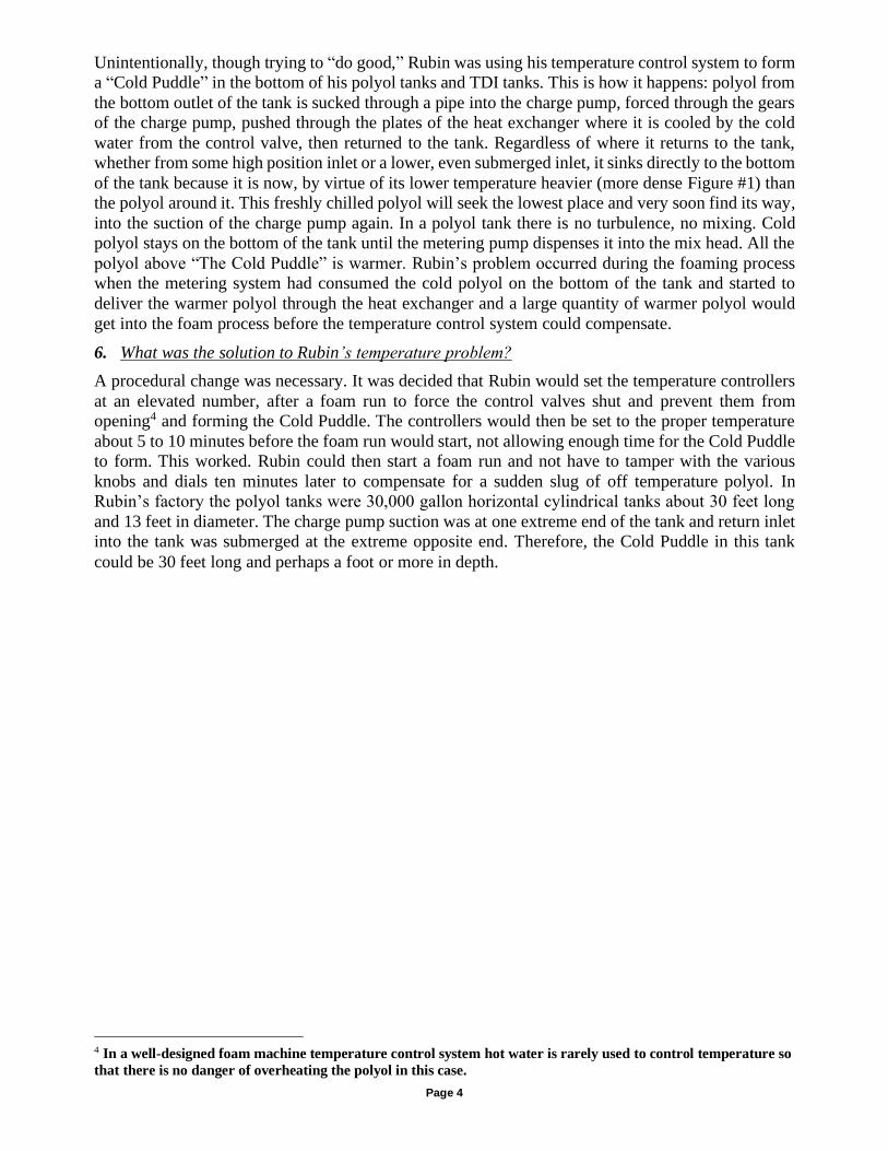
Unintentionally, though trying to “do good,” Rubin was using his temperature control system to form
a “Cold Puddle” in the bottom of his polyol tanks and TDI tanks. This is how it happens: polyol from
the bottom outlet of the tank is sucked through a pipe into the charge pump, forced through the gears
of the charge pump, pushed through the plates of the heat exchanger where it is cooled by the cold
water from the control valve, then returned to the tank. Regardless of where it returns to the tank,
whether from some high position inlet or a lower, even submerged inlet, it sinks directly to the bottom
of the tank because it is now, by virtue of its lower temperature heavier (more dense Figure #1) than
the polyol around it. This freshly chilled polyol will seek the lowest place and very soon find its way,
into the suction of the charge pump again. In a polyol tank there is no turbulence, no mixing. Cold
polyol stays on the bottom of the tank until the metering pump dispenses it into the mix head. All the
polyol above “The Cold Puddle” is warmer. Rubin’s problem occurred during the foaming process
when the metering system had consumed the cold polyol on the bottom of the tank and started to
deliver the warmer polyol through the heat exchanger and a large quantity of warmer polyol would
get into the foam process before the temperature control system could compensate.
6. What was the solution to Rubin’s temperature problem?
A procedural change was necessary. It was decided that Rubin would set the temperature controllers
at an elevated number, after a foam run to force the control valves shut and prevent them from
opening4 and forming the Cold Puddle. The controllers would then be set to the proper temperature
about 5 to 10 minutes before the foam run would start, not allowing enough time for the Cold Puddle
to form. This worked. Rubin could then start a foam run and not have to tamper with the various
knobs and dials ten minutes later to compensate for a sudden slug of off temperature polyol. In
Rubin’s factory the polyol tanks were 30,000 gallon horizontal cylindrical tanks about 30 feet long
and 13 feet in diameter. The charge pump suction was at one extreme end of the tank and return inlet
into the tank was submerged at the extreme opposite end. Therefore, the Cold Puddle in this tank
could be 30 feet long and perhaps a foot or more in depth.
4 In a well-designed foam machine temperature control system hot water is rarely used to control temperature so
that there is no danger of overheating the polyol in this case.
Page 5
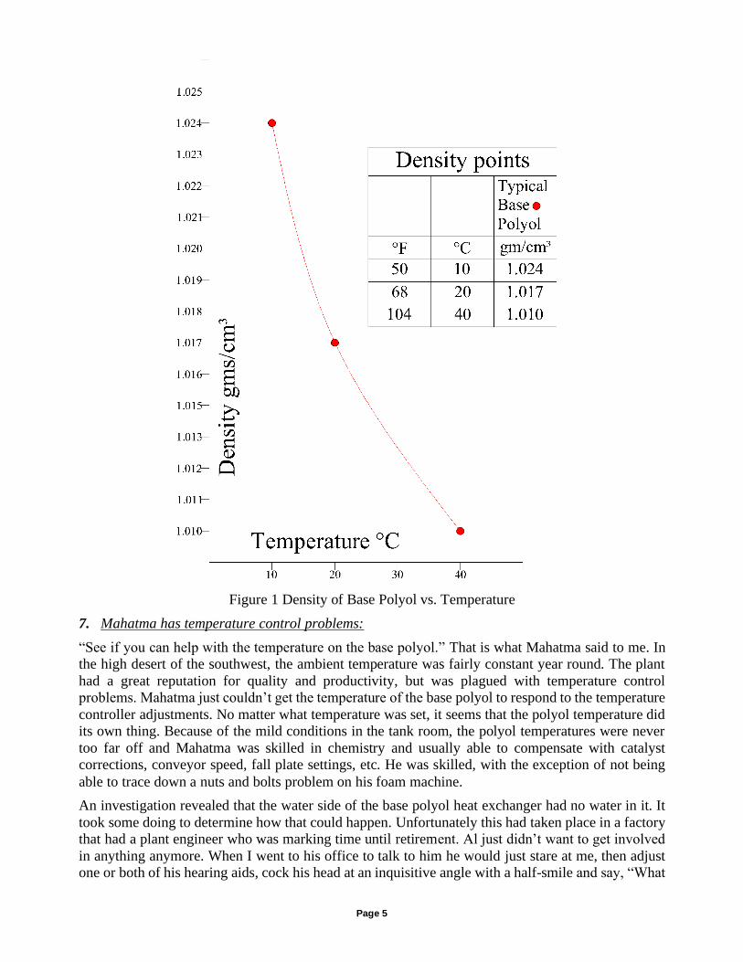
Figure 1 Density of Base Polyol vs. Temperature
7. Mahatma has temperature control problems:
“See if you can help with the temperature on the base polyol.” That is what Mahatma said to me. In
the high desert of the southwest, the ambient temperature was fairly constant year round. The plant
had a great reputation for quality and productivity, but was plagued with temperature control
problems. Mahatma just couldn’t get the temperature of the base polyol to respond to the temperature
controller adjustments. No matter what temperature was set, it seems that the polyol temperature did
its own thing. Because of the mild conditions in the tank room, the polyol temperatures were never
too far off and Mahatma was skilled in chemistry and usually able to compensate with catalyst
corrections, conveyor speed, fall plate settings, etc. He was skilled, with the exception of not being
able to trace down a nuts and bolts problem on his foam machine.
An investigation revealed that the water side of the base polyol heat exchanger had no water in it. It
took some doing to determine how that could happen. Unfortunately this had taken place in a factory
that had a plant engineer who was marking time until retirement. Al just didn’t want to get involved
in anything anymore. When I went to his office to talk to him he would just stare at me, then adjust
one or both of his hearing aids, cock his head at an inquisitive angle with a half-smile and say, “What
Page 6
was that again?” I bet this problem (temperature control) has never been fixed, even though I wrote
it up with an explanation on how to fix it. Here is what happened:
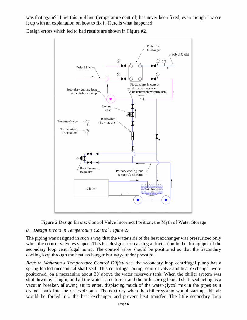
Design errors which led to bad results are shown in Figure #2.
Figure 2 Design Errors: Control Valve Incorrect Position, the Myth of Water Storage
8. Design Errors in Temperature Control Figure 2:
The piping was designed in such a way that the water side of the heat exchanger was pressurized only
when the control valve was open. This is a design error causing a fluctuation in the throughput of the
secondary loop centrifugal pump. The control valve should be positioned so that the Secondary
cooling loop through the heat exchanger is always under pressure.
Back to Mahatma’s Temperature Control Difficulties: the secondary loop centrifugal pump has a
spring loaded mechanical shaft seal. This centrifugal pump, control valve and heat exchanger were
positioned, on a mezzanine about 20' above the water reservoir tank. When the chiller system was
shut down over night, and all the water came to rest and the little spring loaded shaft seal acting as a
vacuum breaker, allowing air to enter, displacing much of the water/glycol mix in the pipes as it
drained back into the reservoir tank. The next day when the chiller system would start up, this air
would be forced into the heat exchanger and prevent heat transfer. The little secondary loop
Page 7
centrifugal had lost its prime, accomplishing nothing, though it was spinning happily. No one noticed.
Except Mahatma. He did not have control of that base polyol temperature.
Control Point at Polyol Outlet of Heat Exchanger: This is an error of design and unfortunately is
entrenched. I call this error inertia. Control valve corrections are made when the temperature probe
signal is compared to a set point within the temperature controller. For example: if the probe
temperature is too high the control valve will open wider, delivering more cold water to the heat
exchanger. However, the entire heat exchanger is already filled with polyol which is too warm and
perhaps half or more of that mass of polyol will be out of the heat exchanger before the temperature
begins to come down toward the set point. The control valve will continue to deliver that amount of
cold water until the probe senses a lower temperature. This arrangement endeavors to adjust the polyol
temperature by adjusting the water temperature, even though there are no temperature transmitters in
the water secondary loop.
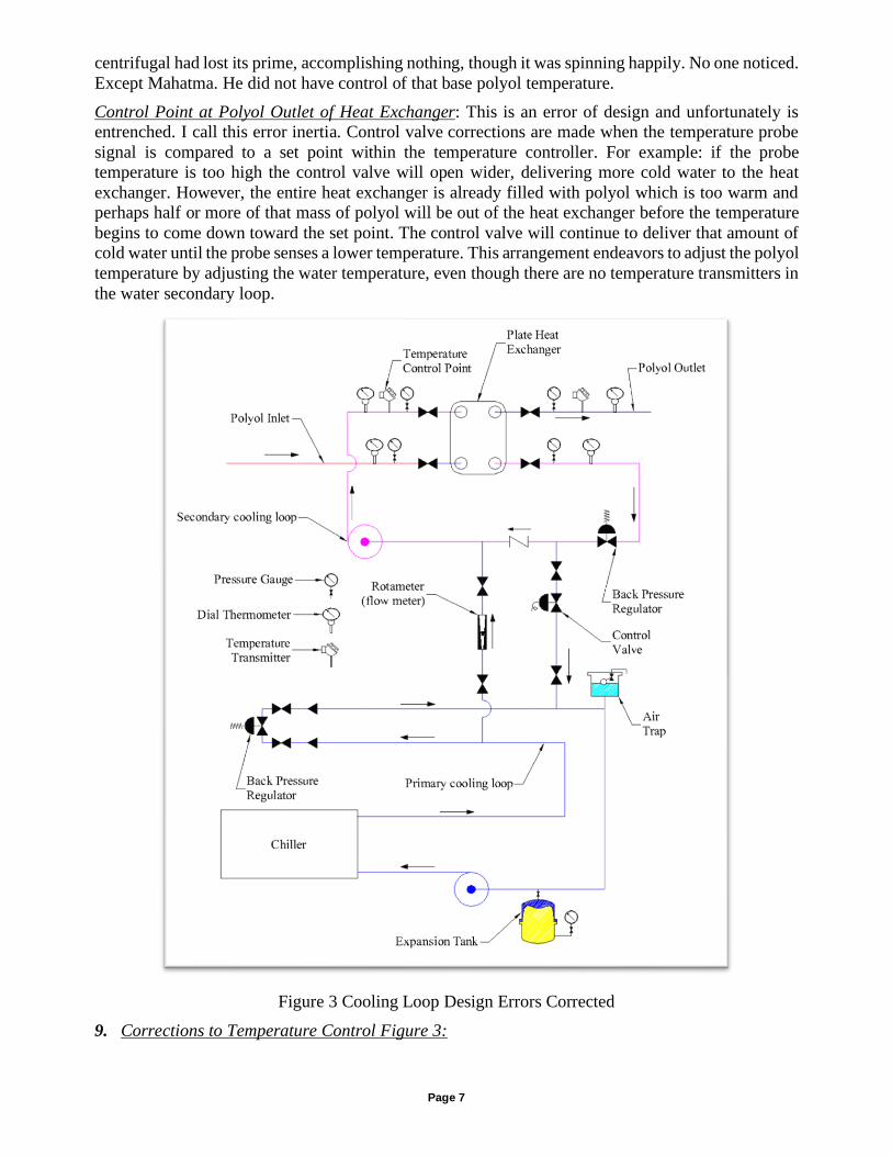
Figure 3 Cooling Loop Design Errors Corrected
9. Corrections to Temperature Control Figure 3:
Page 8
Control valve moved to the correct position allowing pressure from primary cooling loop to
maintain pressure on the entire secondary cooling loop. Pressure and flow fluctuations from control
valve modulation are eliminated.
Additional temperature transmitter and dial thermometers to assist in the understanding of the
function of the system (setup, baseline record, trouble shooting). A temperature transmitter installed
on the water inlet to the heat exchanger is the correct control point (discussed at length in section
17).
Addition of a back pressure regulator to maintain the secondary cooling loop pump at optimal
performance.
10. Two Important Design Criteria in a Chiller System Avoid Two Common Design Errors:
1st A chiller system should be a closed system, always under pressure. A closed system means that
the amount of water/glycol mix in the system is always under pressure whether the system is
operational or shut down. It is called a closed system because there is no place in the system that is
open to atmosphere. In Mahatma’s chiller system (Figure #2), the Water Storage Tank is an open
tank. Pressure in a closed chiller system is maintained by at least one expansion chamber. The
expansion chamber should be of the type which has a rubber bladder charged with air pressure. The
chamber should be positioned in the piping system in such a way that any air passing its inlet/outlet
port cannot enter the water side of the chamber. This is very important. When the system is shut
down and all the water/glycol mix in it is at ambient temperature the expansion chambers should be
about 2/3 to 3/4 full of water/glycol. As the system cools during operation the air charged rubber
bladders will expand in size and maintain the system pressure as the coolant mix contracts with
lowering temperature. Air pressure on the expansion chamber bladders is maintained by back
venting regulators. All this ensures the proper function of centrifugal pumps, control valves, back
pressure regulators in the system and all pump shaft seals will remain seated preventing any air
from entering the system. If there is leakage, it will be outward and self-evident.
2nd The mass of chilled water in a chiller system should be kept to a minimum. There should be no
reservoir of any type in a chiller system. There is no advantage in “storing” cold water. Systems
based on stored ice work5. Systems based on stored water actually diminish the overall efficiency
and performance of the chiller system because they increase the mass of water in the system which
is constantly absorbing heat through the walls of the storage tank. Further load is placed on the
refrigeration condenser plant by shaft work from the additional pumps which are required to keep
water moving through a storage tank. Every watt of electricity that is consumed by the refrigeration
compressor motor and the circulation pumps’ motors generate heat which must be disposed of
through the condenser. If the primary water/glycol loop in a properly functioning chiller system will
not hold at a constant temperature, that is; termperature creeps up when under load, the
refrigeration condenser and evaporator are sized too small! The capacity of a chiller that is
undersized is not increased by adding a water storage tank!
11. How is the Engineer Trapped by These Design Errors?
These two items above are difficult for many engineers to understand because they have been
pressured by management for a fast reaction and do not stop and apply their training to solve the
problem. Management is just responding to the foam chemists blaming his yields problem on
temperature control or lack of it. Adding a tank full of water is an idea which management and the
chemist can believe in and subsequently the engineer can get management off his back, and
management get the chemist off their backs and tell corporate that all they need is a little more
5 The latent heat of fusion of water (i.e.: ice melting or water freezing) = 144BTU/pound ºF. There is no such thing as
latent heat of liquid water. Latent heat only applies when there is a phase change. Ice storage systems are used to reduce
the necessary size of the refrigeration plant by making sufficient ice during off peak demand intervals.
Page 9
money and they will solve the problem. When the problem is not corrected by the addition of a tank
of water, engineering can blame the “Black Art” of foam making. No one questions this.
Management has been convinced by years of exposure to subterfuge by both the engineer and the
chemist. Management, having no technical skills of their own with which to check the engineer’s
proposal and faced with the dysfunctional relationship triangle of engineering, chemist and
management, come to accept as fact that these simple concepts really are not simple, rather they are
unexplainable. Therefore, as long as something is done, even if it is wrong, it is the right thing to
have done.
Phenomena Detrimental to Good Temperature Control:
12. Heat to Run or Chill to Run?:
My experience has always been better when reducing, rather than increasing, the temperature of
polyol or isocyanate through a heat exchanger during a foam pour. Therefore, it is better to store
polyols and isocyanate at an elevated temperature and bring the temperature down through the heat
exchanger to make the pour.
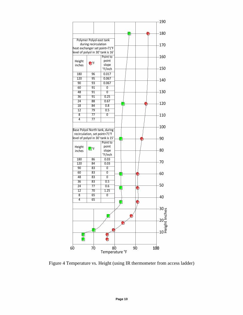
13. The Cold Puddle:
The Cold Puddle is illustrated in Figure #4, showing the actual temperature strata in two 30 foot
high, vertical, cylindrical tanks with capacity of 25,000 gallons. The bottom 8 to 10 inches are
constant temperature. The tanks are flat bottom and the suction of the charge pump is about 8 inches
above the floor of the tank, always leaving approximately 8 inches of material in the bottom of the
tank unused. The cold puddle in these tanks have a significant effect on temperature control during
foaming operations from about 10 inches to 35 inches in depth. That represents about 1,000
kilograms of polyol. At a throughput of 100 kg/min that is 10 minutes of foam making. After the
polyol of the Cold Puddle is consumed, polyol temperature at the outlet of the heat exchanger will
continue to rise unchecked, which is approximately a 15ºF to 20ºF excursion. Now the temperature
control algorithm will open the control valve more and more and is likely to be 100% open before
cooled polyol gets to the probe at the outlet of the heat exchanger at which time the temperature
control algorithm will begin to shut the control valve because the outlet temperature is now too low.
There will probably be several oscillations of this kind before the control valve is stable again.
Page 10
Figure 4 Temperature vs. Height (using IR thermometer from access ladder)
Polymer Polyol east tankduring recirculation
heat exchanger set point=71°Flevel of polyol in 30' tank is 16'
Heightinches
°F
Point topointslope
°F/inch
180 96 0.017120 95 0.06790 93 0.06760 91 048 91 036 91 0.2524 88 0.6718 84 0.812 79 0.58 77 04 77
60 70 80 90 100Temperature °F
Base Polyol North tank, duringrecirculation, set point=71°F
level of polyol in 30' tank is 15'
Heightinches
°F
Point topointslope
°F/inch
180 86 0.03120 84 0.0390 83 060 83 048 83 036 83 0.524 77 0.612 70 1.258 65 04 65
10
20
30
40
50
60
70
80
90
100
110
120
130
140
150
160
170
190
180
He
igh
t In
che
s
100
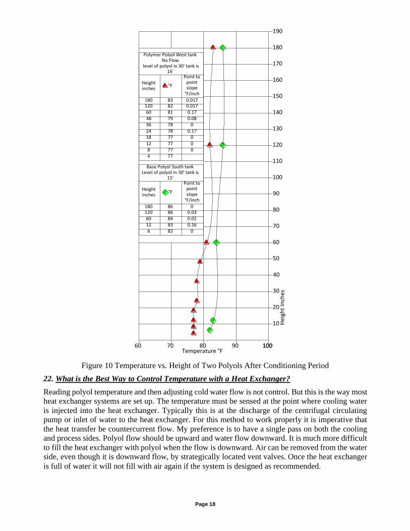
Polymer Polyol West tankNo Flow
level of polyol in 30' tank is16'
Heightinches
°F
Point topointslope
°F/inch
180 83 0.017120 82 0.01760 81 0.1748 79 0.0836 78 024 78 0.1718 77 012 77 08 77 04 77
Temperature °F
10
20
30
40
50
60
70
80
90
100
110
120
130
140
150
160
170
190
180
He
igh
t In
che
s
60 70 80 90 100100
Base Polyol South tankLevel of polyol in 30' tank is
15'
Heightinches
°F
Point topointslope
°F/inch
180 86 0120 86 0.0360 84 0.0212 83 0.166 82 0
I do this kind of thing all the time:
1) Get the view you want on your ACAD screen.
2) Select "Copy Link" from the Edit menu
3) In your other doc (Word, PPT, Excel,...) select Paste Special
under the Edit menu
4) Select "Picture (Enhanced Metafile).
Page 11
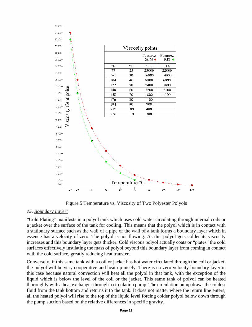
14. Invisible Pipe:
The Invisible Pipe is a phenomenon associated with polyols. The Cold Puddle is a special case of the
Invisible Pipe. A basic knowledge of viscosity is necessary to understand the Invisible Pipe.6 All
polyols have viscosity characteristics which are extremely temperature sensitive. Figure 5 is an
example of this. That is; as temperature goes down, viscosity goes up rapidly. Cold polyol will flow
from an inlet to an outlet downhill virtually without mixing with warmer polyol around it. A look
inside a tank of polyol with a strong spotlight reveals this phenomenon. Not only is the colder liquid
more viscous, it is visible because it has a slightly different density than the warmer polyol around it
and it has a different refraction of light. Therefore, you can see the flow as if it were in a pipe but
there is no visible pipe. Why should this be interesting to the foam chemist? On the surface of this
cold flow a thin layer of surrounding warmer liquid “clings” to the flowing cold liquid and is drawn
along the same Invisible Pipe pathway to the outlet of the tank which leads to the charge pump and
the heat exchanger, through the metering pump, around in a circuit of pipe back to the inlet to the
tank. This is the only mixing which occurs. This is the reason it takes many hours, perhaps days to
lower the temperature of a tank of polyol using just the heat exchanger. Another interesting aspect of
the Invisible Pipe is if the inlet of polyol is above the level of the liquid in the tank the impingement
of this falling liquid on the liquid surface will always cause air to be forced under the surface of the
liquid and consequent air bubbles to be carried along the path of the Invisible Pipe down through the
outlet, through temperature control and metering system piping increasing the amount of air bubbles
in the polyol. Over time the Invisible Pipe expands to become a Cold Puddle.
6Briefly; viscosity is the measure of a liquid’s resistance to flow. The greater numerical value of the viscosity , the greater the resistance
to flow. A peculiar characteristic of these higher viscosity materials is that flow is almost always laminar. Laminar is the opposite of turbulent. Laminar is like the lamination in plywood and turbulence is like the strands of wood in particleboard (or OSB). Water flow, for example, is almost always turbulent. In turbulence there is mixing. Honey flowing is always laminar. In laminar flow there is very little
mixing. Viscosity is one of two main things which determine whether or not flow is turbulent. The other is the diameter of the pipe through which the liquid is flowing. For a low viscosity fluid such as water, at a specific throughput the larger the diameter the more likely flow is laminar and the smaller the diameter the more likely flow is turbulent. On a modern foam machine polyol flow can be assumed to
always be laminar and TDI flow can be assumed to always be turbulent.
Page 12
Figure 5 Temperature vs. Viscosity of Two Polyester Polyols
15. Boundary Layer:
“Cold Plating” manifests in a polyol tank which uses cold water circulating through internal coils or
a jacket over the surface of the tank for cooling. This means that the polyol which is in contact with
a stationary surface such as the wall of a pipe or the wall of a tank forms a boundary layer which in
essence has a velocity of zero. The polyol is not flowing. As this polyol gets colder its viscosity
increases and this boundary layer gets thicker. Cold viscous polyol actually coats or “plates” the cold
surfaces effectively insulating the mass of polyol beyond this boundary layer from coming in contact
with the cold surface, greatly reducing heat transfer.
Conversely, if this same tank with a coil or jacket has hot water circulated through the coil or jacket,
the polyol will be very cooperative and heat up nicely. There is no zero-velocity boundary layer in
this case because natural convection will heat all the polyol in that tank, with the exception of the
liquid which is below the level of the coil or the jacket. This same tank of polyol can be heated
thoroughly with a heat exchanger through a circulation pump. The circulation pump draws the coldest
fluid from the tank bottom and returns it to the tank. It does not matter where the return line enters,
all the heated polyol will rise to the top of the liquid level forcing colder polyol below down through
the pump suction based on the relative differences in specific gravity.
Page 13
16. Entrainment of Air:
Air becomes entrained or entrapped in polyols usually during unloading truck loads or railcar loads
into storage tanks or during the recirculation process during foaming operations. Tank trucks or tank
cars are usually pressurized during unloading processes with compressed Nitrogen or compressed air.
This in itself does not entrain air but as the polyol enters the tank through an overhead pipe system,
there is much splashing as the velocity of the downward stream of polyol causes air to be forced under
the surface of the liquid in the tank creating millions of bubbles (like soap suds) to cover the top
surface and infiltrated throughout the polyol in the tank. When the tank truck or railcar becomes
empty, the compressed air chases the polyol through the loading pipe system creating tremendous
frothing at the outlet into the tank, especially if this fill pipe is submerged. During recirculation
through the metering and temperature control piping if the fluid returned to the tank is dropped in
from above the surface of the polyol in the tank the same frothing occurs, but it is much worse because
of the “Invisible Pipe.”
17. Efforts to Break Up the Temperature Layers In Polyols and Remove Entrained Air Bubbles:
There are many ideas and methods to break up temperature layers; some are good, others are not.
Filling geometry, recirculation geometry, mixing methods are discussed
18. Filling Geometry:
Filling a tank from the rail siding or tank truck: The polyol typically arrives hot from the supplier,
perhaps 140ºF or hotter. Because of this it is best to have at least two tanks for the high use polyols.
Load one tank while the other is being used for running the foam. Hot polyol has the advantage of a
low viscosity which will allow entrained air bubbles to rise rapidly to the surface and burst. Therefore,
after unloading, let that polyol sit in the tank for at least a day with the temperature falling naturally,
allowing the air to surface. Any attempt of cooling at this stage will infiltrate the piping system and
heat exchanger with entrained air causing major quality problems later. All the systems I have
designed loaded the polyol from the top of the tank and directed the flow against the inside vertical
wall of the tank in an effort to reduce splashing. There is no best way for loading because all methods
result in entrained air. If loading is through a submerged pipe, the compressed air chasing the polyol
through the loading pipe when the railcar or truck empties will make a major contribution to entrained
air. Therefore the conditioning period of 24 hours or more is vital. Let the air bubbles rise to the
surface!
Unloading pipe and process pipe should be completely separate: It is an error of management and
engineering to believe they are saving money during the installation of piping systems by
incorporating a design which shares or combines pipe runs, pumps and valves for loading and
processing. It is not a money savings. It will create quality problems and possibly safety and
environmental calamities.
If the polyol loading pump is also used as the metering pump or feed pump to circulate polyol through
the heat exchanger to the suction side of the metering pump, the shared piping will be filled with air
or nitrogen at the end of the loading process when the rail car or tank truck empty. This air remains
in the pipe, after lining up the valves to the “run” position, infiltrating the polyol metering system and
heat exchanger. Many hours of recirculation are required to get that polyol to flush the air back to the
tank where it attempts to surface before being sucked into the metering system again.
If for some reason, lunch break, smoke break, substitute employee, etc. the valves are not properly
aligned for loading or metering, a dangerous overfill or overpressure may occur.
Recirculation through a submerged return pipe connection: Piping should be designed such that once
the system is full of polyol, it will not drain out spontaneously when pumps are shutdown.
Page 14
This drainage occurs when the open end of the return line pipe enters the tank above the level of the
liquid in the tank. The correct piping scheme is to install the return pipe so that its open end is very
close to the bottom of the tank.
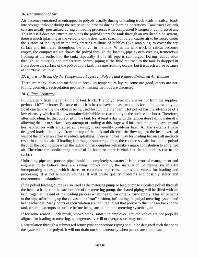
In foam plant “A”, where I was installing a new hermetic foam machine, the very tall storage tanks
were in a room with a very high ceiling. All the piping had been installed just under the steel framing
supporting the roof. This placed the supply and return piping runs some 40 feet above the tank room
floor. In this plant, the polyol return lines were connected to the top of the tank and literally poured
the polyol from the top of the tank onto the standing polyol in the tank which could be up to a 25 foot
drop or more. The plant engineer had heard that if you attach a half inch trade size link chain from
the center of the return pipe to the bottom of the tank that splashing will be prevented. The legend is
that polyol would follow that chain very neatly to the surface of the polyol in the tank without
splashing. Mr. High (a trusted maintenance mechanic) and I investigated this claim. What we
observed through the top manway in the tank, with a strong flashlight, while the feed pump was
running was a very violently splashing “waterfall” of polyol into the tank, generating tremendous
quantities of frothing polyol on the surface of the liquid far below.
Figure 6: Before corrections, this piping configuration creates a significant pressure from a static
liquid column on the discharge side of the feed pump. When the feed pump was shut down, the pump
rotated backwards as all the polyol in the piping system drained backward through the pipe, through
the heat exchanger, through the pump, back to the bottom of the tank. There is nothing to stop air
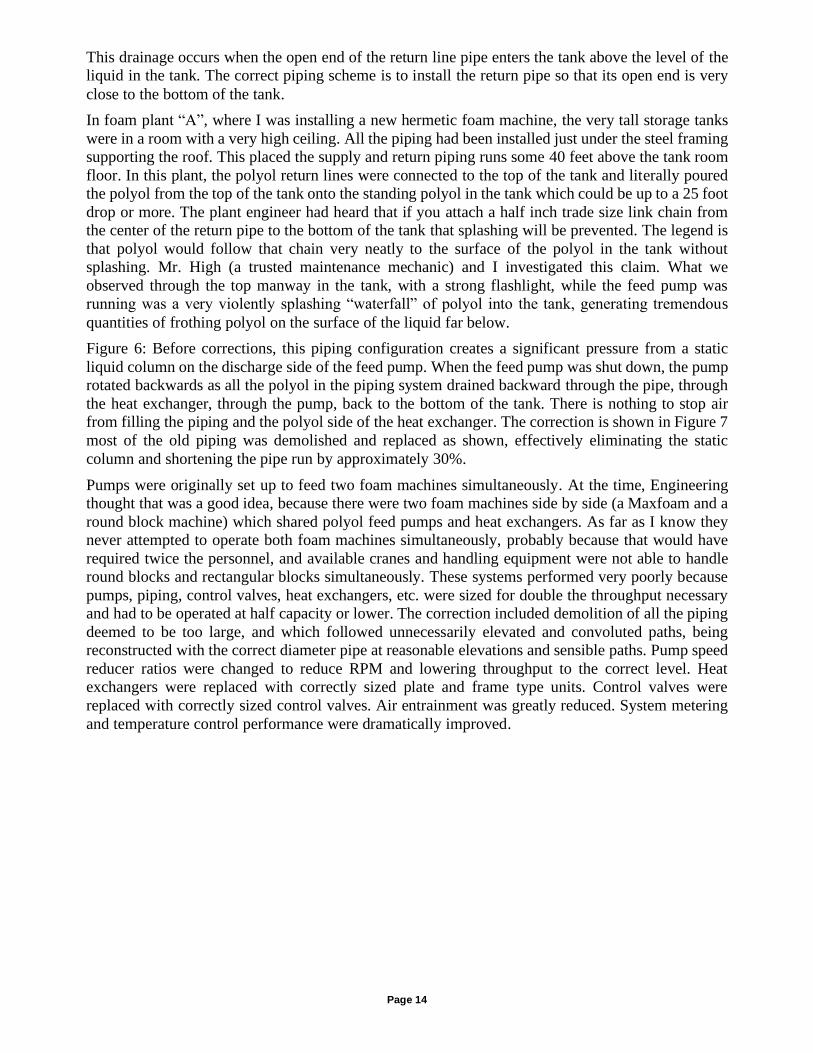
from filling the piping and the polyol side of the heat exchanger. The correction is shown in Figure 7
most of the old piping was demolished and replaced as shown, effectively eliminating the static
column and shortening the pipe run by approximately 30%.
Pumps were originally set up to feed two foam machines simultaneously. At the time, Engineering
thought that was a good idea, because there were two foam machines side by side (a Maxfoam and a
round block machine) which shared polyol feed pumps and heat exchangers. As far as I know they
never attempted to operate both foam machines simultaneously, probably because that would have
required twice the personnel, and available cranes and handling equipment were not able to handle
round blocks and rectangular blocks simultaneously. These systems performed very poorly because
pumps, piping, control valves, heat exchangers, etc. were sized for double the throughput necessary
and had to be operated at half capacity or lower. The correction included demolition of all the piping
deemed to be too large, and which followed unnecessarily elevated and convoluted paths, being
reconstructed with the correct diameter pipe at reasonable elevations and sensible paths. Pump speed
reducer ratios were changed to reduce RPM and lowering throughput to the correct level. Heat
exchangers were replaced with correctly sized plate and frame type units. Control valves were
replaced with correctly sized control valves. Air entrainment was greatly reduced. System metering
and temperature control performance were dramatically improved.
Page 15
Figure 6 Before Corrections to Piping in Plant “A”
Figure 7 After Corrections to Piping in Plant "A"
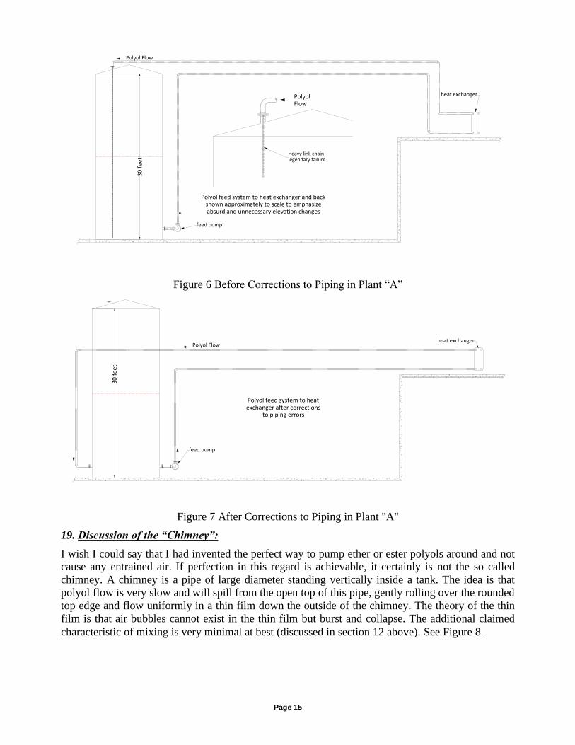
19. Discussion of the “Chimney”:
I wish I could say that I had invented the perfect way to pump ether or ester polyols around and not
cause any entrained air. If perfection in this regard is achievable, it certainly is not the so called
chimney. A chimney is a pipe of large diameter standing vertically inside a tank. The idea is that
polyol flow is very slow and will spill from the open top of this pipe, gently rolling over the rounded
top edge and flow uniformly in a thin film down the outside of the chimney. The theory of the thin
film is that air bubbles cannot exist in the thin film but burst and collapse. The additional claimed
characteristic of mixing is very minimal at best (discussed in section 12 above). See Figure 8.
Polyol Flow
30
fee
t
heat exchanger
Polyol feed system to heat exchanger and backshown approximately to scale to emphasizeabsurd and unnecessary elevation changes
Heavy link chainlegendary failure
feed pump
PolyolFlow
Polyol Flow
30
fee
t
heat exchanger
Polyol feed system to heatexchanger after corrections
to piping errors
feed pump
Page 16
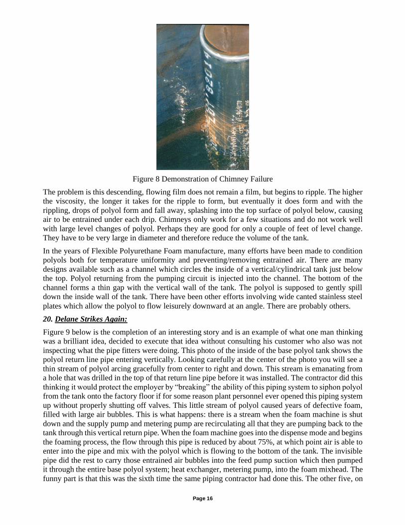
Figure 8 Demonstration of Chimney Failure
The problem is this descending, flowing film does not remain a film, but begins to ripple. The higher
the viscosity, the longer it takes for the ripple to form, but eventually it does form and with the
rippling, drops of polyol form and fall away, splashing into the top surface of polyol below, causing
air to be entrained under each drip. Chimneys only work for a few situations and do not work well
with large level changes of polyol. Perhaps they are good for only a couple of feet of level change.
They have to be very large in diameter and therefore reduce the volume of the tank.
In the years of Flexible Polyurethane Foam manufacture, many efforts have been made to condition
polyols both for temperature uniformity and preventing/removing entrained air. There are many
designs available such as a channel which circles the inside of a vertical/cylindrical tank just below
the top. Polyol returning from the pumping circuit is injected into the channel. The bottom of the
channel forms a thin gap with the vertical wall of the tank. The polyol is supposed to gently spill
down the inside wall of the tank. There have been other efforts involving wide canted stainless steel
plates which allow the polyol to flow leisurely downward at an angle. There are probably others.
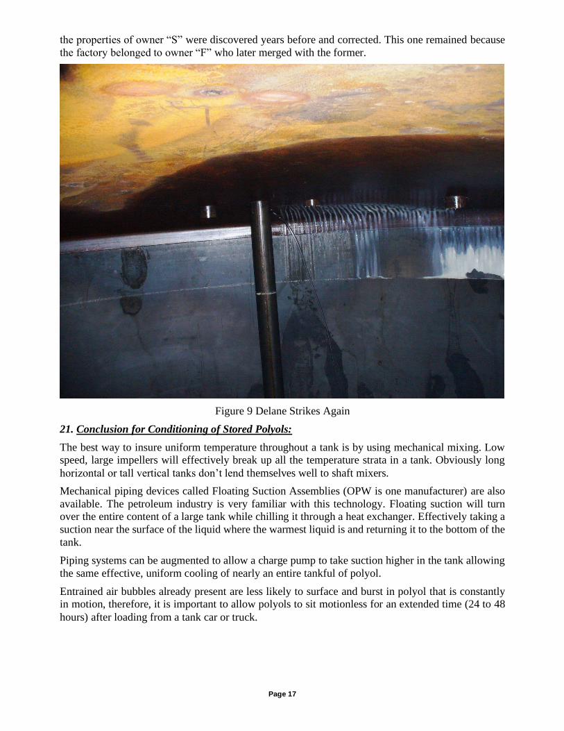
20. Delane Strikes Again:
Figure 9 below is the completion of an interesting story and is an example of what one man thinking
was a brilliant idea, decided to execute that idea without consulting his customer who also was not
inspecting what the pipe fitters were doing. This photo of the inside of the base polyol tank shows the
polyol return line pipe entering vertically. Looking carefully at the center of the photo you will see a
thin stream of polyol arcing gracefully from center to right and down. This stream is emanating from
a hole that was drilled in the top of that return line pipe before it was installed. The contractor did this
thinking it would protect the employer by “breaking” the ability of this piping system to siphon polyol
from the tank onto the factory floor if for some reason plant personnel ever opened this piping system
up without properly shutting off valves. This little stream of polyol caused years of defective foam,
filled with large air bubbles. This is what happens: there is a stream when the foam machine is shut
down and the supply pump and metering pump are recirculating all that they are pumping back to the
tank through this vertical return pipe. When the foam machine goes into the dispense mode and begins
the foaming process, the flow through this pipe is reduced by about 75%, at which point air is able to
enter into the pipe and mix with the polyol which is flowing to the bottom of the tank. The invisible
pipe did the rest to carry those entrained air bubbles into the feed pump suction which then pumped
it through the entire base polyol system; heat exchanger, metering pump, into the foam mixhead. The
funny part is that this was the sixth time the same piping contractor had done this. The other five, on
Page 17
the properties of owner “S” were discovered years before and corrected. This one remained because
the factory belonged to owner “F” who later merged with the former.
Figure 9 Delane Strikes Again
21. Conclusion for Conditioning of Stored Polyols:
The best way to insure uniform temperature throughout a tank is by using mechanical mixing. Low
speed, large impellers will effectively break up all the temperature strata in a tank. Obviously long
horizontal or tall vertical tanks don’t lend themselves well to shaft mixers.
Mechanical piping devices called Floating Suction Assemblies (OPW is one manufacturer) are also
available. The petroleum industry is very familiar with this technology. Floating suction will turn
over the entire content of a large tank while chilling it through a heat exchanger. Effectively taking a
suction near the surface of the liquid where the warmest liquid is and returning it to the bottom of the
tank.
Piping systems can be augmented to allow a charge pump to take suction higher in the tank allowing
the same effective, uniform cooling of nearly an entire tankful of polyol.
Entrained air bubbles already present are less likely to surface and burst in polyol that is constantly
in motion, therefore, it is important to allow polyols to sit motionless for an extended time (24 to 48
hours) after loading from a tank car or truck.
Page 18
Figure 10 Temperature vs. Height of Two Polyols After Conditioning Period
22. What is the Best Way to Control Temperature with a Heat Exchanger?
Reading polyol temperature and then adjusting cold water flow is not control. But this is the way most
heat exchanger systems are set up. The temperature must be sensed at the point where cooling water
is injected into the heat exchanger. Typically this is at the discharge of the centrifugal circulating
pump or inlet of water to the heat exchanger. For this method to work properly it is imperative that
the heat transfer be countercurrent flow. My preference is to have a single pass on both the cooling
and process sides. Polyol flow should be upward and water flow downward. It is much more difficult
to fill the heat exchanger with polyol when the flow is downward. Air can be removed from the water
side, even though it is downward flow, by strategically located vent valves. Once the heat exchanger
is full of water it will not fill with air again if the system is designed as recommended.
Polymer Polyol east tankduring recirculation
heat exchanger set point=71°Flevel of polyol in 30' tank is 16'
Heightinches
°F
Point topointslope
°F/inch
180 96 0.017120 95 0.06790 93 0.06760 91 048 91 036 91 0.2524 88 0.6718 84 0.812 79 0.58 77 04 77
60 70 80 90 100Temperature °F
Base Polyol North tank, duringrecirculation, set point=71°F
level of polyol in 30' tank is 15'
Heightinches
°F
Point topointslope
°F/inch
180 86 0.03120 84 0.0390 83 060 83 048 83 036 83 0.524 77 0.612 70 1.258 65 04 65
10
20
30
40
50
60
70
80
90
100
110
120
130
140
150
160
170
190
180
Hei
ght
Inch
es
100
Polymer Polyol West tankNo Flow
level of polyol in 30' tank is16'
Heightinches
°F
Point topointslope
°F/inch
180 83 0.017120 82 0.01760 81 0.1748 79 0.0836 78 024 78 0.1718 77 012 77 08 77 04 77
Temperature °F
10
20
30
40
50
60
70
80
90
100
110
120
130
140
150
160
170
190
180
Hei
ght
Inch
es
60 70 80 90 100100
Base Polyol South tankLevel of polyol in 30' tank is
15'
Heightinches
°F
Point topointslope
°F/inch
180 86 0120 86 0.0360 84 0.0212 83 0.166 82 0
I do this kind of thing all the time:
1) Get the view you want on your ACAD screen.
2) Select "Copy Link" from the Edit menu
3) In your other doc (Word, PPT, Excel,...) select Paste Special
under the Edit menu
4) Select "Picture (Enhanced Metafile).
Page 19
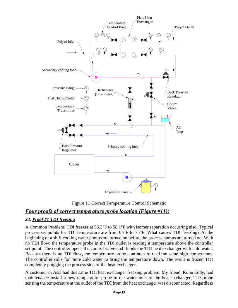
Figure 11 Correct Temperature Control Schematic
Four proofs of correct temperature probe location (Figure #11):
23. Proof #1 TDI freezing
A Common Problem: TDI freezes at 56.3°F to 58.1°F with isomer separation occurring also. Typical
process set points for TDI temperature are from 65°F to 75°F. What causes TDI freezing? At the
beginning of a shift cooling water pumps are turned on before the process pumps are turned on. With
no TDI flow; the temperature probe in the TDI outlet is reading a temperature above the controller
set point. The controller opens the control valve and floods the TDI heat exchanger with cold water.
Because there is no TDI flow, the temperature probe continues to read the same high temperature.
The controller calls for more cold water to bring the temperature down. The result is frozen TDI
completely plugging the process side of the heat exchanger.
A customer in Asia had this same TDI heat exchanger freezing problem. My friend, Kuhn Eddy, had
maintenance install a new temperature probe to the water inlet of the heat exchanger. The probe
sensing the temperature at the outlet of the TDI from the heat exchanger was disconnected. Regardless
Back Pressure
Regulator
Control
Valve
Rotameter
(flow meter)Back Pressure
Regulator
Polyol Outlet
Polyol Inlet
Secondary cooling loop
Plate Heat
Exchanger
Pressure Gauge
Dial Thermometer
Temperature
Transmitter
Temperature
Control Point
Chiller
Primary cooling loop
Expansion Tank
AirTrap
Page 20
of which pumps are turned on first, the chilled water entering the heat exchanger will not be below
the set point temperature. They report no more freeze ups and improved temperature control accuracy
and repeatability.
24. Proof #2 Temperature probe in the process out of the heat exchanger causes oscillation.
Plate exchangers are very efficient but have a large mass of polyol and water in them. If the probe is
in the outlet of the Polyol (which seems logical) it does not take into account that large mass of polyol
and water which is likely to be the wrong temperature. If the polyol inlet temperature changes up or
down, the heat exchanger is filled with the "wrong temperature" polyol before the probe on the polyol
outlet senses the wrong temperature (the water loop is also at the wrong temperature). When the off
spec temp is noted, the control valve is adjusted to bring the polyol back into spec. But, there is a
waiting period before the effect of the control valve adjustment is sensed. In the meantime, off spec
foam has been poured onto the conveyor because the polyol temperature is incorrect. If the control
valve adjustment was too severe or not enough, there is another adjustment made by the controller
and another waiting period must transpire before a third correction is made or not made. Assuming
that the waiting period was correct in the controller, there is either a perfect adjustment which still
suffers from a waiting period, a "too much" adjustment which creates oscillation or a "not enough"
adjustment which also requires at least one more waiting period to pass before temperature is
corrected again.
Place the temperature controller’s probe in the water inlet of the heat exchanger! In the case of the
temperature probe being in the inlet of the water; the controller is actually sensing the temperature of
the fluid in which it is directly adjusting the temperature. Because water flow is typically much more,
perhaps 2 times or more, than the polyol flow and because the water flow is turbulent creating mixing
and therefore uniform temperature distribution (polyol flow is laminar in a plate heat exchanger,
creating temperature layers), changes in the control valve setting are sensed very rapidly by the
sensing probe. In a plate heat exchanger, the outlet of the polyol temperature is very close to and
directly proportional to the inlet of the water temperature (countercurrent flow), the best place to
control the heat exchanger is at the inlet of the water.
For example: as more load is placed on the heat exchanger the water temperature will rise causing an
immediate control valve adjustment. The entire heat exchanger full of polyol will be treated
immediately by the adjustment.
25. Proof #3 “Monte Carlo Funnel Experiment”
Adjusting the water control valve to control polyol temperature measured at the outlet of the heat
exchanger is analogous to the second and third rules of the “Monte Carlo Funnel Experiment”.7 Rule
2 of that experiment is termed “tampering,” which is stable but doubles process error. Rule 3 is
“oscillation and unstable.” The funnel experiment as explained by Dr. W. Edwards Deming is not a
joke but a very valuable tool to understand process control.
7 Out of the Crisis Dr. W. Edwards Deming pages 327 through 332 © 1986 Massachusetts Institute of Technology
Page 21
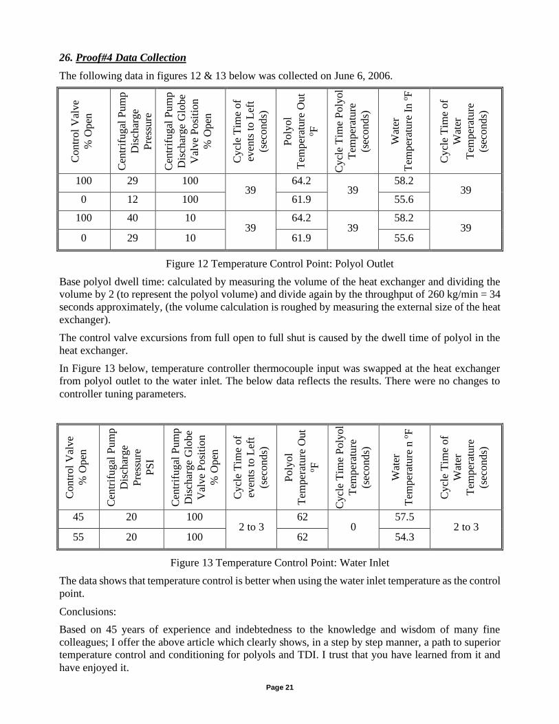
26. Proof#4 Data Collection
The following data in figures 12 & 13 below was collected on June 6, 2006. C
ontr
ol
Val
ve
% O
pen
Cen
trif
ugal
Pum
p
Dis
char
ge
Pre
ssure
Cen
trif
ugal
Pum
p
Dis
char
ge
Glo
be
Val
ve
Posi
tion
% O
pen
Cycl
e T
ime
of
even
ts t
o L
eft
(sec
onds)
Poly
ol
Tem
per
ature
Out
oF
Cycl
e T
ime
Poly
ol
Tem
per
ature
(sec
onds)
Wat
er
Tem
per
ature
In o
F
Cycl
e T
ime
of
Wat
er
Tem
per
ature
(sec
onds)
100 29 100 39
64.2 39
58.2 39
0 12 100 61.9 55.6
100 40 10 39
64.2 39
58.2 39
0 29 10 61.9 55.6
Figure 12 Temperature Control Point: Polyol Outlet
Base polyol dwell time: calculated by measuring the volume of the heat exchanger and dividing the
volume by 2 (to represent the polyol volume) and divide again by the throughput of 260 kg/min = 34
seconds approximately, (the volume calculation is roughed by measuring the external size of the heat
exchanger).
The control valve excursions from full open to full shut is caused by the dwell time of polyol in the
heat exchanger.
In Figure 13 below, temperature controller thermocouple input was swapped at the heat exchanger
from polyol outlet to the water inlet. The below data reflects the results. There were no changes to
controller tuning parameters.
Contr
ol
Val
ve
% O
pen
Cen
trif
ugal
Pum
p
Dis
char
ge
Pre
ssure
PS
I
Cen
trif
ugal
Pum
p
Dis
char
ge
Glo
be
Val
ve
Posi
tion
% O
pen
Cycl
e T
ime
of
even
ts t
o L
eft
(sec
onds)
Poly
ol
Tem
per
ature
Out
oF
Cycl
e T
ime
Poly
ol
Tem
per
ature
(sec
onds)
Wat
er
Tem
per
ature
n o
F
Cycl
e T
ime
of
Wat
er
Tem
per
ature
(sec
onds)
45 20 100 2 to 3
62 0
57.5 2 to 3
55 20 100 62 54.3
Figure 13 Temperature Control Point: Water Inlet
The data shows that temperature control is better when using the water inlet temperature as the control
point.
Conclusions:
Based on 45 years of experience and indebtedness to the knowledge and wisdom of many fine
colleagues; I offer the above article which clearly shows, in a step by step manner, a path to superior
temperature control and conditioning for polyols and TDI. I trust that you have learned from it and
have enjoyed it.


