Download - CA TALOGUE - LENNOX EMEA

HV
AC
CA
TA
LO
GU
E
CA
TALO
GU
E
AIR CONDITIONING & HEATING
AIR TREATMENT & VENTILATION
CONTROL & SUPERVISION
HV
AC

at your service!
LENNOX SERVICE
A team of experts, supporting you throughout
your products' life cycle.
INVESTMENT IN EQUIPMENT
COMMISSIONING
SERVICE CONTRACT
BUILDING MANAGEMENT
SYSTEM
REMOTE ANALYTICS
TRAINING
MANUFACTURERVISIT & AUDIT
SPARE PARTS
TECHNICAL ASSISTANCE
REPAIRS
UNIT UPGRADE : • EFFICIENCY • IAQ
RETROFIT / A2L

Contents | Air Conditioning & Heating 1/2
WHO ARE WE? 3
A WORLD OF APPLICATIONS 4
REGULATIONS AND CERTIFICATIONS 6
AIR CONDITIONING & HEATING Refrigerants Cooling/Heating capacity & Airflow rate Page
Rooftops
eNeRGy 53 - 170 kW / 50 - 175 kW 13500 - 27000 m3/h
19
eNeRGy+ 97 - 160 kW / 102 - 164 kW 15500 - 27000 m3/h
19
e-eNeRGy 109 - 163 kW / 112 - 168 kW 18900 - 27000 m3/h
19
e-Baltic 31 - 207 kW / 30 - 207 kW 5700 - 35000 m3/h
27
Baltic 22 - 122 kW / 21 - 115 kW 4200 - 23500 m3/h
33
Baltic 47 - 90 kW / 60 - 117 kW 7100 - 14500 m3/h
--- 33
Flexair 85 - 217 kW / 79 - 222 kW 15000 - 39000 m3/h
39
Flexair 85 - 170 kW / 112 - 127 kW 15000 - 30000 m3/h
--- 39
Chillers & Heat Pumps
eComfort 170 - 400 kW 53
eComfort
20 - 210 kW / 20 - 210 kW 61
Neosys 200 - 1000 kW / 200 - 500 kW 79
Ecolean 40 - 200 kW / 50 - 200 kW 87
Aqua4 50 - 300 kW / 50 - 350 kW --- 93
Genesis R513A
R1234ze
R134a 220 - 1600 kW / 230 - 1440 kW 101
Genesis R513A
R1234ze
R134a 400 - 1650 kW / 400 - 1950 kW 101
Hydrolean 25 - 160 kW / 30 - 170 kW 117
MWC/MRC 180 - 380 kW / 200 - 450 kW 125
Roomtops
Flatair 22 - 33 kW / 20 - 29 kW 3700 - 5600 m3/h
--- 135
Compactair 22 - 82 kW / 20 - 80 kW 5400 - 18700 m3/h
--- 141
Aqualean 2 - 40 kW / 2,6 - 50 kW 285 - 7500 m3/h
--- 147
Condensing Units ASC/ASH 19,7 - 228 kW / 19,8 - 218 kW --- 155
VRF e-Lite HFC 8 - 270 kW / 3 - 96 HP 163
1

Contents | Air Treatment & Ventilation /Control & Supervision 2/2
AIR TREATMENT & VENTILATION Refrigerants Cooling/Heating capacity & Airflow rate Page
Fan Coil Units
Allegra II WATER 0.5 - 8.9 kW / 0.7 - 11.6 kW 60 - 1670 m3/h
177
Armonia II WATER 1.5 - 10.8 kW / 1.9 - 13.5 kW 225 - 1536 m3/h
181
Comfair HD WATER 1.5 - 3.9 kW / 1.8 - 4.9 kW 234 - 620 m3/h
187
Inalto WATER 3 - 28 kW / 3,7 - 37,7 kW 516 - 5668 m3/h
191
Comfair HH/HV WATER 2,8 - 50,6 kW / 4,9 - 60 kW 840 - 8000 m3/h
195
Axil/Equitherm WATER 4 - 20 kW / 12 - 105 kW 1600 - 9100 m3/h
--- 199
Fresh Air Units
MiniAir 320 - 4700 m3/h --- 205
MaxiAir 1500 - 15000 m3/h --- 205
e-MovAir 17 - 146 kW / 20 - 140 kW 3500 - 30000 m3/h
--- 209
Air Handling Units
CleanAir LX --- 2 - 550 kW / 10 - 1300 kW 1000 - 100000 m3/h
217
OneAir --- 1100 - 100000 m3/h 221
Air-Cooled Condensers & Dry-coolers
Neostar --- HFC 18 - 1280 kW --- 225
FC/FI Neostar --- WATER 20 - 1200 kW --- 225
V-King --- WATER 50 - 2200 kW --- 225
CONTROL & SUPERVISION Refrigerants Cooling/Heating capacity & Airflow rate Page
Control & Supervision
LennoxCloud --- --- --- --- 229
Adalink II --- --- --- --- 233
LennoxOneWeb --- --- --- --- 233
LennoxHydroControl --- --- --- --- 233
2

3
OUR KEY FIGURES
900 employees in Europe
3 European production sites: Genas, Longvic and Burgos
Quality certification: ISO 9001 - 14001 - OHSAS 18001
1 European training centre
1 European HVAC&R development centre
9 subsidiaries and sales offices
Commercial presence over 46 countries
WHO ARE WE?
LENNOX EMEA (Europe, Middle-East, Africa), a division of Lennox International Incorporated (LII), is a leading provider of refrigeration, heating, air conditioning and air handling solutions. We are committed to assisting our clients in their projects in order to provide optimal and sustainable solutions.
At LENNOX EMEA, we ensure that every employee develops within the group and contributes to our customers' projects success. Our reputation grows every day by providing maximum comfort and efficiency through our air conditioning and refrigeration solutions.
Our reputation as a leading market player is based on simple principles that guide our actions: the ability to listen to our customers, knowledge of their business and understanding of their needs.
The commitment and expertise of all LENNOX EMEA employees are key to the trust our customers place in us every day and to ensuring the continuity of our relationships.
More than ever, LENNOX EMEA is committed to rising to tomorrow's challenges alongside you.
Ricardo FREITASVP, Managing Director LENNOX EMEA

4
CAFÉS RESTAURANTS In a dining setting, guest comfort is critical to an enjoyable experience. But hard-working staff need to be taken care of as well. Lennox solutions provide reliable, efficient cooling and heating configurations that help create the perfect environment for food preparation and dining.
CONVENIENCE STORESIn smaller format stores, customer comfort and efficiency are key priorities. Lennox compact and aesthetic solutions provide the ideal temperature while optimising the energy footprint.
CULTURAL AND SPORT CENTRESPerformance and sports venues can be a challenging space to maintain temperature and humidity. Lennox solutions are designed to be easily modified for variable heating and cooling needs to accommodate any size crowd effectively and efficiently.
DATA CENTRESIn data centres, heat management is crucial. Lennox units provide reliably efficient cooling solutions that help data centre operators reduce the energy costs while maximising uptime.
FOOD RETAILIn large, open spaces, priorities for HVAC performance include both comfort and efficiency. With Lennox one doesn’t have to come at the cost of the other, with products and technology that deliver ideal heating and cooling solutions tailor-made for spacious retail settings.
A world of applications

5
HOSPITALSFor patients and guests, a healthcare environment can be an unfamiliar and uncomfortable place. Lennox products feature customizable applications with medical-grade air quality components to help enhance patient comfort and maintain a sanitary setting for everyone.
HOTELSThe environment in a hospitality setting is closely associated with customer satisfaction. Lennox can optimise guest comfort with a range of heating and cooling solutions while providing property owners with the most efficient options to maximize their HVAC investment in every location.
INDUSTRYIn large, open industrial spaces, keeping the set temperature constant across the entire building is of utmost importance. Lennox solutions offer industrial spaces accurate temperature, regardless of the activity or time.
NON-FOOD RETAILIn large, open spaces, priorities for HVAC performance include both comfort and efficiency. With Lennox one doesn’t have to come at the cost of the other, with products and technology that deliver ideal heating and cooling solutions tailor-made for spacious retail settings.
OFFICE BUILDINGSA facility with an optimal HVAC system can have a direct impact on employee performance. Offering system-wide temperature control, as well as individual office control, Lennox can help enhance employee focus in a comfortable working environment.
SHOPPING MALLSA pleasant store environment means longer visit times and potentially increased sales. Lennox customized products and controls offer retail spaces the most effective heating and cooling options, regardless of their size or configuration.
STORAGE & LOGISTICS A key success metric in distribution applications is keeping employees productive when fulfilling orders. Lennox products and technology have been engineered to maintain comfort without compromising efficiency to deliver a win/win for staff and facility owners.

Chiller range:
• Cooling only + Heat pump 20 - 180 kW
• Heat pump 170 - 400 kW
• Cooling only 400 - 650 kW
• New rooftop platform
• Water cooled chiller range
• Propane rooftop
& chiller ranges
R32
SHORT-TERM MEDIUM-TERM LONG-TERM
R32
NATURALREFRIGERANT
The LII group has a 125-year history inventing new technologies, developing new products and continuously enhancing product quality and improvements that address the world’s heating, cooling and air quality challenges.
Following the group’s lead, we at Lennox EMEA, are ready and committed to tackling climate change by designing, manufacturing and marketing efficient and environmentally-friendlier HVAC-R solutions. Developing products with progressively less carbon impact – through greater energy efficiency and use of refrigerants with lower global warming potential (GWP) is at the heart of our product strategy.
For the last few years, we have been dedicated to aligning the design of our climate control and refrigeration solutions with the European EcoDesign and F-Gas regulations.
Our Lennox HVAC units have recently been upgraded to meet or exceed the new EcoDesign 2021 thresholds, while we are continuing our refrigerant transition towards R32 and lower GWP refrigerants.
Product Efficiency and Innovation
OVERVIEW OF OUR SUSTAINABLE JOURNEY
6

117%
181%
117%
149%
161%
196%
227%
115%
133%
115%
115%
115%
138%
189%
138%
161%
179%
200%
252%
125%
137%
125%
125%
125%
100% 125% 150% 175% 200% 225% 250%
ECODESIGN Directive 2009/125/EC
The KYOTO Agreement (1997), the COP 21 (Paris 2015) and the COP 22 (Marrakech 2016) set targets for limiting global warming to 1.5 °C. The Ecodesign Directive 2009/125/EC defines a framework for all energy-consuming equipment. Voted on in 2007, and implemented since 2008, it aims to reduce the power consumption of electronic devices through better design (ecodesign).
The implementation of the Ecodesign Directive is split into several areas of related products, called ”lots”, focusing on the product areas with the most substantial energy consumption and the highest potential for energy savings.
The Ecodesign Directive is mandatory for all products marketed and used in the European Union (CE marking).
Regulations and Certifications
MINIMUM EFFICIENCY PERFORMANCE STANDARD (MEPS)Requirements for minimum efficiency performance are set in Europe as a consequence of the implementation of the Ecodesign Directive. The regulation has been introduced step-by-step and the requirements gradually intensified over time.
With the introduction of the second and last tier of ENER LOT 21, or directive (EU) 2016/2281 for air heating and cooling products, high temperature process chillers and fan coil units, most of our units have had their minimum energy performance levels increased, and have thus been optimised to meet or exceed the new thresholds.
FLATAIRCOMPACTAIR
e-Lite(VRF)
BALTICFLEXAIReNeRGy
>400 kWNEOSYS
<400 kWHYDROLEAN
MWC
>400 kWMWC
Minimum seasonal energy efficency
SEER - 2018 Unitary, Rooftop & Chiller ranges
SCOP - 2015 Chiller rangesSCOP - 2018 Unitary & Rooftop ranges
SCOP - 2017 Chiller rangesSCOP - 2021 Unitary & Rooftop ranges
The Aqualean, Baltic water cooled, Flexair water cooled ranges are impacted, but no minimum performance to be reached. The eNeRGy without condenser range is impacted by the EU 2014/1253 (ventilation units). The ASC / ASH condensing units are not impacted.
SEER - 2021 Unitary, Rooftop & Chiller ranges
<400 kWECOLEAN
eCOMFORTNEOSYS
ECODESIGN2021
SAME DESIGN
IMPROVEDEFFICIENCY
7

WHAT IS F-GAS?The chlorofluorocarbon (CF) and hydrofluorocarbon (HCFC) refrigerants used in cooling systems today are considered to be powerful greenhouse gases. To prevent climate changes and global warming, the European Commission has adopted a roadmap to reduce global emissions by 2050.
EU Regulation No. 517/2014, known as F-Gas:# Lays down rules regarding the containment, use, recovery and destruction of fluorinated greenhouse gases and the related measures. # Lays down the conditions for marketing certain products and equipment containing HFCs. # Imposes conditions on certain specific uses of fluorinated greenhouse gases. # Sets quantitative limits (quotas) for marketing HFCs.
This Regulation is for all companies that install, maintain and sell equipment containing refrigerants, as well as those that handle and distribute them.
DESIGN & MAINTENANCE OF EQUIPMENT All equipment must be designed to prevent accidental discharge of greenhouse gases. Technical measures are taken upstream in order to minimise these leaks (refer to Regulation (EU) No. 517/2014 specifying the procedures for leakage checks).The F-Gas regulation on fluorinated gases imposes:
# Frequent inspections. # Qualification of companies & their agents.
QUOTAS: "PHASE DOWN"The European Commission is responsible for assigning the HFC quotas available on the market to companies. This measure aims to reduce the total amount of HFCs available on the market, so that the remaining share of HFCs (21% in 2030) is only used for the maintenance of existing equipment and/or for certain specific applications for which there is no alternative.
31%
93%
63%
45%
24% 21%
100%100%
80%
60%
40%
20%
0%2015 2016
201720182020
20212023
20242026
20272029
2030
Marketing timetable (expressed in t CO2e)
WHAT IS GWP?All HFC refrigerants placed on the market are classified according to a Global Warming Potential (GWP). The GWP is an index that characterises the action of a chemical compound on the greenhouse effect within a given time. The reference refrigerant is CO2, of which the GWP is 1. The lower the index, the more environmentally-friendly the refrigerant. New equipment is subject to restrictions based on the GWP of the refrigerants. So, refrigerants with a GWP greater than 2500 have been banned in new installations since January 2020.The availability of HFCs will be limited by falling production quotas.
F-Gas | EU Regulation No. 517/2014
8

, THE OBVIOUS ALTERNATIVE TO R410AIn the quest of alternative solutions to this HFC quota reduction, R32 is an obvious choice to replace R410A. It already makes up 50% of its composition, and it has a number of other key advantages:
Low cost Pure substance Many providers due to no patent
Already available on residential market GWP = 675
R513A & R1234ze , OPTIMUM REPLACEMENTS FOR R134a
R513A and R1234ze are excellent alternatives to R134a. These high-density refrigerants are ideal for large capacity chillers, with screw compressors. Both refrigerants are easy to retrofit to R134a systems – and because they are much less damaging
to the environment, they benefit from lower taxes and leak test demands.
Refrigerants overview according to their GWP
Refrigerants
R40
4A
R41
0A
R13
4a
R45
2B
R32
R51
3A
R45
4B
R12
34ze
R29
0 (
Prop
ane)
GWP
2 500 1 500 10
3922 2088 1430 698 675 631 466 6 3
F-Gas | EU Regulation No. 517/2014
9

ISO A guarantee of quality
The ISO family of standards has been developed to address various aspects of quality management. ISO certification enables us to guarantee the circulation of safe and quality products on the market. The various ISO standards also contribute to the fact that companies such as ours optimise their production methods, while guaranteeing our employees' safety. Our company is ISO-certified and thus meets quality assurance criteria:ISO 9001 - lays down the criteria applicable to a quality management system. ISO 14001 - lays down the criteria applicable to an environmental management system. OHSAS 18001 - establishes the method for setting up an occupational health and safety management system.
CE
The CE marking was created within the framework of European technical harmonisation legislation. It represents a manufacturer's commitment that its product complies with the regulatory requirements for free movement throughout the European Union. This marking is mandatory for all products covered by one or more European regulatory texts that explicitly provide for it. As a manufacturer, and in order to allow the circulation of our products, we rigorously ensure the conformity of our products with regard to the essential requirements defined by European legislation.
Our declaration of conformity specifies the applicable guidelines for the entire catalogue by product range.
Regulations and Certifications
10

11
Lennox Services
At Lennox, we know that purchasing equipment is just the beginning of your HVAC investment. That’s why we are committed to offer you unique support over the entire life of your equipment.
From commissioning to modernisation of your HVAC system, our service team is here to provide you with the right expertise in order to ensure its optimal running and extended lifespan.
LENNOX CAREBenefit from OEM expertise for peace of mind.Commissioning: our technicians perform all startup procedures and ensure your system is running efficiently and reliably from the start.
Maintenance: HVAC units often operate under harsh conditions that can affect their lifetime and performance, leading to extra energy consumption and operational costs. Partnering with our experts is the guarantee maintenance checks and audits are performed at the right time.
Repairs: count on our factory-trained technicians to efficiently solve problems and reduce downtime.
SPARE PARTSOrder them quickly and easily.For your own repairs, our dedicated team supports you throughout the process of spare parts procurement – from the selection to the delivery.
MODERNISATIONTake your HVAC equipment to the next level. Rely on our team to make sure your existing equipment keeps running efficiently. Our upgrade solutions – from latest fan technology, Indoor Air Quality (IAQ), controls & connectivity, to lower GWP refrigerants – will help you to keep a high performing building.

LENNOX EMEAUNIVERSITY
ON-SITECOURSES
VIRTUALCOURSES
Training is one of the most important investments you can make in your business, and your future. The best technicians, sales and business people are life-long learners. The technician who’s up to speed on the latest industry technology earns a customer’s loyalty. A salesperson who sells an extra unit per week can bring in a significant extra in annual profit. Business owners and office staff who take the time to enhance their own knowledge and skills will create a thriving, growing workplace.
Lennox EMEA University offers training programmes, designed to help you hone your skills, expand your knowledge in an ever changing technological and regulatory environment and excel in your field. With our face-to-face, virtual classroom or webinar offerings, you can choose what best works for you.
All our trainings are delivered by our experienced instructors who have extensive knowledge in the HVAC-R industry and Lennox equipment.
Learn how to install and service Lennox units.
Learn how to handle A2L refrigerants.
Sessions offered at various locations.
Training, with no travel. We’re bringing the classroom to you.
Keep up with the latest industry trends and regulations.

PACKAGED AIR HANDLING UNITS
eNeRGy 19
ROOFTOP UNITS
e-Baltic 27
Baltic 33
Flexair 39

14
A rooftop, as the name suggests, is an HVAC unit located on the roof of a building. A rooftop can be installed on many different types of buildings, such as warehouses, shopping malls, industrial workshops, supermarkets, restaurants. The aim of a rooftop is to provide heated and cooled air to a defined area. The air is distributed through ductwork that define its route.
A rooftop is a compact air handler that is installed externally, and, therefore, designed and constructed to face all the elements. Unlike other HVAC units, a rooftop is self-contained and thus not connected to any other decentralized component. Rooftops represent an easy and simple way of providing air-conditioning: an all-in-one unit with plug and play installation.
Our range of rooftops offers flexibility in terms of design and sizing to be able to answer multiple applications, whether you are looking to equip an existing installation or a new one.
ROOFTOP UNITS | Product overview
WHAT IS A ROOFTOP ?

Cooling capacity
0 kW 50 kW 100 kW 150 kW 200 kW 250 kW
Airflow rate
eNeRGy
Baltic
e-Baltic
Flexair
Baltic
Flexair
eNeRGy
Baltic
e-Baltic
Flexair
Baltic Flexair
15
PACKAGED AIR HANDLING UNITS AIR COOLED
eNeRGy 53 - 170 kW50 - 175 kW 13500 - 27000 m3/h
eNeRGy+
97 - 160 kW102 - 164 kW 15500 - 27000 m3/h
e-eNeRGy 120 - 178 kW114 - 171 kW 18900 - 27000 m3/h
-
ROOFTOP UNITS AIR COOLED / WATER COOLED
e-Baltic 31 - 207 kW30 - 207 kW 5700 - 35000 m3/h
Baltic 22 - 122 kW21 - 115 kW 4200 - 23500 m3/h
Flexair 85 - 217 kW79 - 222 kW 15000 - 39000 m3/h
Baltic 47 - 90 kW60 - 117 kW 7100 - 14500 m3/h
-
Flexair 85 - 170 kW112 - 127 kW 15000 - 30000 m3/h
-
Air/Air
Water/Air
Cooling capacity
Heating capacity
Airflow rate
Cafés Restaurants
Non food retail
Food retail
Shopping malls
Storage & Logistics
Industry

16
Standard equipment Option
Additional configurations/options are available on request, please contact your sales representative.
eNeR
Gy
eNeR
Gy+
e-eN
eRG
y
e-Ba
ltic
eBB
H
e-Ba
ltic
eBFH
BALT
ICB
AC
/BA
H
FLEX
AIR
FAC
/FA
H
CASING Pre-coated galvanised steel (white) - - - - -Pre-coated aluminium (white) - -
INSULATION M0 fire-proof classification
25 mm double-skin - - -50 mm double-skin
CONDENSATE DRAIN PAN
Removable drain pan
Aluminium drain pan
AIR FLOW CONFIGURATION
Downflow supply
Horizontal supply
Upflow supply - -Downflow return
Horizontal return
Upflow return
AIR FILTER G3
G4
Refillable G4
M5 (ePM10 50%)
F7 (ePM1 50%)
F9 (ePM1 85%)
AUXILIARY HEATING
Modulating gas burner
Natural gas burner
Propane gas burner
Electric heater (2-step or modulating 0-100%)
Electric pre-heater (modulating 0-100%)
Hot water coil
ANTI-CORROSION PROTECTION
LenGuard anti-corrosion protection on evaporator coil
LenGuard anti-corrosion protection on condenser coil
ENERGY RECOVERY
Cross flow plate heat exchanger - - - - -Rotary wheel heat exchanger
Thermodynamic heat recovery - -eRecovery on food refrigeration systems
SUPPLY FAN Direct drive & variable speed centrifugal EC plug fan (low & high pressure)
CONDENSER Air cooled : Variable speed & low noise axial EC fan
Water cooled : Plate exchanger - - - - -
ECONOMISER Motorised free-cooling/heating
EXHAUST Gravity exhaust damper
Power exhaust axial fan & gravity damper
Centrifugal EC exhaust plug fan (direct drive and variable speed) & gravity damper
ROOF CURB Non adjustable non assembled roof curb - - -Adjustable roof curb
Multidirectional airflow roof curb - - -
PACKING Container packing
ROOFTOP UNITS | Available equipment

17
Standard equipment Option
Additional configurations/options are available on request, please contact your sales representative.
eNeR
Gy
eNeR
Gy+
e-eN
eRG
y
e-Ba
ltic
eBB
H
e-Ba
ltic
eBFH
BALT
ICB
AC
/BA
H
FLEX
AIR
FAC
/FA
H
REFRIGERANT R32 - - - -R410A - - -Refrigerant leak detection
COMPRESSOR Inverter - - - - - -Multiscroll
Tandem
Silent start
Compressor noise jacket
EXPANSION VALVE Electronic (bi-flow for heat pump)
CONTROL eClimatic (programmable controler)
Regulation on supply or ambiant temperature
7 time zones per day with 4 different operating modes
Dirty filter alarm
Dynamic defrost
Alternate defrost
Morning anticipation
Dynamic setpoint
Variable airflow management of supply fan
eFlow airflow rate on display
Variable airflow management of condenser fan
Economiser power stage & free-cooling/heating
Energy recovery module power stage (if energy recovery option)
Compressors capacity steps (up to 4)
Auxiliary heating capacity steps
Intelligent fresh air management (Patent 03 50616)
COMMUNICATION Master/Slave operation up to 24 units
Distance Management System : LennoxCloud connectivity
Distance Management System : LennoxOneWeb, ...
External dry & analogic contacts board
ModBus RS485 interface
LonWorks® FTT10 interface
BACnet RS485 interface
ModBus & BACnet TCP/IP interface
DISPLAY INTERFACE
DC (comfort display)
DM (multi-units display)
DS (service display)
CONTROL AND SAFETY DEVICES
Main disconnect switch
Smoke detector
Fire thermostat
Soft starter/Air sock control
CO2 control
Humidity control
Multi-ambient temperature
Variable airflow management/constant pressure
Energy meter

18
NOTES

eNeRGyHigh efficiency packaged air treatment units
LENNOX participates in the ECP programme for RT.
Check ongoing validity of certificate : www.eurovent-certification.com
AIR COOLED 97 - 160 kW 102 - 164 kW 15500 - 27000 m3/h
AIR COOLED 109 - 163 kW 112 - 168 kW 18900 - 27000 m3/h
AIR COOLED 53 - 170 kW 50 - 175 kW 13500 - 27000 m3/h

20
# Optimised design and integration of highly efficient components enabling energy savings.
# Modular concept that allows various combinations of thermodynamic circuits and air treatment sections, ensuring high adaptability with different building requirements.
# Tunnel flow design allows larger sections with more filtration options to improve indoor air quality.
# Low noise level thanks to availability of several sound attenuation options.
eNeRGy | High efficiency packaged air treatment units
AIRFLOW
# Several available airflow configurations: top, bottom or horizontal, to fit each building's need.
# Adjustable roof curb to fit the building's architecture.
# Extraction and/or recovery section(s) integrated in the indoor section of the unit offering compactness and easy installation.
THERMODYNAMIC SYSTEM
# Tandem or inverter scroll compressors allowing capacity modulation.
# Variable refrigerant control with electronic expansion valve.
# Fan with variable speed EC motor and swept blades, enabling control of the high and low floating pressure for optimum operation.
# Large surface exchangers for highly efficient heat transfer.
# Easy access to compressors enabling faster maintenance operations.
REMOTE MONITORING
# Connectivity through LennoxCloud (LENNOX WEB PORTAL for Multi sites / Multi units).
# BMS through: - LennoxOneWeb.
- ADALINK II* (LENNOX WEB SERVER One site / Several units).
- LennoxTouch.* * Check the availability of this feature in your country.
CONTROL
# eClimatic electronic controller and intelligent control parameters optimising part-load efficiency.
# Integrated communication solutions offering flexibility (master/slave, Modbus, BACnet LonWorks®).
# Several display solutions for different access levels.
DS Service display
DM Multi-Rooftop
display
DC Comfort display
eCLIMATIC
Photos and illustrations are not contractual.

21
CASING & DESIGN
# Modular concept with various combinations of thermodynamic circuits and air treatment sections.# Structure built with 50mm aluminum profile for high rigidity and reduced weight.# Double skin panels with 50 mm of Rockwool insulation, built with pre-painted aluminum panels for high corrosion resistance.# Inclined removable drain pan in aluminum for easy disinfecting.# Easy Lock on the panels permits right or left hand opening or complete dismounting, allowing easy disinfecting and
maintenance.
HEAT RECOVERY
# Thermodynamic heat recovery, ideal for mild climates.
# Heat recovery wheel, with both fresh and return air sections protected by G4 filters.
# eRecovery, to recover free heat produced by food refrigeration systems.
AIR TREATMENT
# EC motor fans ensuring a precise temperature for better comfort and energy savings.
# Analogue filter detection informs when the filters must be changed.
# IAQ kits for improved indoor air quality within the building:
- G4 (standard) - G4+F7 (ePM1 85%) - G4+F7+F9 (ePM1 95%) - UV-C lamps. - Ionization.
AUXILIARY HEATING DEVICES
# Different options depending on the energy source available on site:
- Hot water coil. - Condensing gas burner. - Electric heater. - Electric preheater.

22
E(A) 014(B) A(C) H(D) 85(E) F(F) (A) E = eNeRGy(B) Airflow (x 1000 m3/h)(C) A = Air cooled condensation(D) H = Heat pump - N = No condensing unit(E) Cooling capacity in kW(F) F = Standard scroll compressor
eNeRGy | Nomenclature and general data
Air cooled version Heat pump units
eNeRGy014AH 016AH 019AH
055 065 075 085 105 066 076 086 106 124Nominal thermal performances - Cooling modeCooling capacity (1) kW 52,3 65,2 72,7 84,0 102,0 67,7 76,7 86,9 107,8 111,8Total Power Input kW 14,80 19,47 22,89 25,43 32,34 21,37 24,07 26,94 33,96 38,07EER net (1) 3,53 3,35 3,18 3,30 3,15 3,17 3,19 3,23 3,18 2,94Nominal thermal performances - Heating modeHeating capacity (2) kW 48,2 63,0 68,4 80,9 97,7 66,8 76,6 87,0 106,8 107,2Total Power Input kW 11,09 16,65 17,98 21,70 28,60 16,93 18,96 22,68 31,00 30,34COP net (2) 4,35 3,78 3,81 3,73 3,41 3,94 4,04 3,84 3,45 3,54Seasonal efficiencies - Cooling modeSeasonal Energy Efficiency Ratio - SEER (3) 4,63 4,62 4,93 4,48 4,26 4,42 4,28 4,30 4,31 4,21Seasonal energy efficiency - s,c (4) % 182 182 194 176 167 174 168 169 169 165Eurovent energy efficiency class - Part load operation B B B B B B B B B BSeasonal efficiencies - Heating modeSeasonal Coefficient of Performance - SCOP (5) 3,66 3,52 3,52 3,41 3,25 3,64 3,39 3,32 3,28 3,32Seasonal energy efficiency - s,h (6) % 143 138 138 133 127 143 132 130 128 130Eurovent energy efficiency class - Part load operation B B B B B B B B B BAuxiliary heatingGas heating capacity - Standard / High
kW
82 / 100Electric heater capacity - Standard / High 36 / 108Electric pre-heater capacity - Standard / High 36 / 108Hot water coil capacityAir inlet 20°C/Water
69,6 / 122,2
69,6 / 122,2
69,6 / 122,2
74,5 / 132
74,5 / 132
81,9 / 146,9
81,9 / 146,9
81,9 / 146,9
81,9 / 146,9
81,9 / 146,9
Ventilation dataMinimum airflow rate
m3/h9500 9500 9500 10500 10500 13000 13000 13000 13000 13000
Nominal airflow rate 13500 13500 13500 15500 15500 18900 18900 18900 18900 18900Maximum airflow rate 16000 24000 24000 24000 24000 20000 24000 24000 24000 24000Acoustic data - Standard unitOutdoor sound power
dB(A)76,4 77,8 76,5 79,1 80,9 81,9 81,4 82,0 83,0 82,7
Indoor blower outlet sound power 78,9 78,9 78,9 82,5 82,5 90,0 90,0 90,0 90,0 87,6Electrical dataMaximum power kW 29,3 37,3 37,7 42,4 44,5 37,3 37,7 42,4 44,5 48,9Maximum current A 135,8 124,4 148,8 171,4 183,7 124,4 148,8 171,4 183,7 187,9Starting current A 49,1 61,4 77,0 88,9 76,8 61,4 77,0 88,9 76,8 82,4Short circuit current kA 10 10 10 10 10 10 10 10 10 10Refrigeration circuitNumber of circuits 2 2 2 2 2 2 2 2 2 2Number of compressors 3 4 4 4 4 4 4 4 4 4Refrigerant load kg 18 18 33,8 33,8 34,2 20 33 33 32,8 33,7
(1) Cooling mode : According to EN14511 nominal conditions - Outdoor temperature 35°C DB - Indoor temperature 27°C DB / 19°C WB(2) Heating mode : According to EN14511 nominal conditions - Outdoor temperature 7°C DB / 6°C WB - Indoor temperature 20°C DB(3) SEER in accordance with standard EN14825.(4) Space cooling energy efficiency following Ecodesign regulation EU 2016/2281 (5) SCOP in accordance with standard EN 14825 (average climate conditions).(6) Space heating energy efficiency following Ecodesign regulation EU 2016/2281.

23
E(A) 014(B) A(C) H(D) 85(E) F(F) (A) E = eNeRGy(B) Airflow (x 1000 m3/h)(C) A = Air cooled condensation(D) H = Heat pump - N = No condensing unit(E) Cooling capacity in kW(F) F = Standard scroll compressor
eNeRGy | Nomenclature and general data
Air cooled version Heat pump units
eNeRGy022AH 024AH 027AH
077 087 107 140 078 088 108 126 141 160 180Nominal thermal performances - Cooling modeCooling capacity (1) kW 75,3 86,1 106,9 132,0 79,0 89,8 111,9 122,4 137,5 154,7 165,7Total Power Input kW 24,36 27,06 34,05 42,35 24,59 27,33 34,51 36,93 43,59 51,34 58,97EER net (1) 3,09 3,18 3,14 3,12 3,21 3,29 3,24 3,31 3,15 3,01 2,81Nominal thermal performances - Heating modeHeating capacity (2) kW 75,8 87,7 107,6 129,1 76,9 89,3 109,9 121,0 135,9 148,3 178,5Total Power Input kW 18,88 22,61 30,49 37,89 18,39 22,05 29,28 30,72 39,22 41,55 56,13COP net (2) 4,01 3,88 3,53 3,41 4,18 4,05 3,75 3,94 3,46 3,57 3,18Seasonal efficiencies - Cooling modeSeasonal Energy Efficiency Ratio - SEER (3) 4,22 4,28 4,28 3,95 4,38 4,43 4,41 4,43 4,35 4,02 4,00Seasonal energy efficiency - s,c (4) % 166 168 168 155 172 174 173 174 171 158 157Eurovent energy efficiency class - Part load operation B B B B B B B B B B BSeasonal efficiencies - Heating modeSeasonal Coefficient of Performance - SCOP (5) 3,40 3,38 3,35 3,34 3,51 3,50 3,51 3,49 3,29 3,30 3,28Seasonal energy efficiency - s,h (6) % 133 132 131 130 137 137 137 137 129 129 128Eurovent energy efficiency class - Part load operation B B B B B B B B B B BAuxiliary heatingGas heating capacity - Standard / High
kW
100 / 200Electric heater capacity - Standard / High 54 / 144Electric pre-heater capacity - Standard / High 54 / 144Hot water coil capacityAir inlet 20°C/Water
111,4 / 176,5
111,4 / 176,5
111,4 / 176,5
111,4 / 176,5
117,9 / 188
117,9 / 188
117,9 / 188
117,9 / 188
117,9 / 188
123,9 / 198,6
123,9 / 198,6
Ventilation dataMinimum airflow rate
m3/h15000 15000 15000 15000 17000 17000 17000 17000 17000 18500 18500
Nominal airflow rate 21600 21600 21600 21600 24300 24300 24300 24300 24300 27000 27000Maximum airflow rate 24000 24000 24000 24000 28000 28000 32000 32000 32000 32000 32000Acoustic data - Standard unitOutdoor sound power
dB(A)83,8 84,2 84,8 85,1 79,7 80,6 81,9 81,3 82,2 83,6 84,9
Indoor blower outlet sound power 90,5 90,6 90,6 90,9 85,3 85,5 85,5 85,9 85,9 88,8 88,8Electrical dataMaximum power kW 37,7 42,4 44,5 64,8 41,5 46,2 48,3 52,2 68,6 81,4 89,7Maximum current A 148,8 171,4 183,7 239,3 154,9 177,5 189,8 193,6 245,4 264,6 317,0Starting current A 77,0 88,9 76,8 106,6 83,1 95,0 82,9 88,1 112,7 131,9 149,3Short circuit current kA 10 10 10 10 10 10 10 10 10 10 10Refrigeration circuitNumber of circuits 2 2 2 2 2 2 2 2 2 2 2Number of compressors 2 2 4 4 2 2 4 4 4 4 4Refrigerant load kg 31,9 32,1 32,7 43,6 27,7 27,9 28,2 42,6 43,4 44,2 44,2
(1) Cooling mode : According to EN14511 nominal conditions - Outdoor temperature 35°C DB - Indoor temperature 27°C DB / 19°C WB(2) Heating mode : According to EN14511 nominal conditions - Outdoor temperature 7°C DB / 6°C WB - Indoor temperature 20°C DB(3) SEER in accordance with standard EN14825.(4) Space cooling energy efficiency following Ecodesign regulation EU 2016/2281 (5) SCOP in accordance with standard EN 14825 (average climate conditions).(6) Space heating energy efficiency following Ecodesign regulation EU 2016/2281.

24
E(A) 014(B) A(C) H(D) 85(E) F(F) (A) E = eNeRGy(B) Airflow (x 1000 m3/h)(C) A = Air cooled condensation(D) H = Heat pump - N = No condensing unit(E) Cooling capacity in kW(F) F = Standard scroll compressor
Air cooled version Heat pump units
eNeRGy+016AH 019AH 027AH
105 124 160Nominal thermal performances - Cooling modeCooling capacity (1) kW 102,7 121,6 172,7Total Power Input kW 31,84 40,49 57,98EER net (1) 3,23 3,00 2,98Nominal thermal performances - Heating modeHeating capacity (2) kW 96,7 118,0 166,5Total Power Input kW 29,26 37,86 53,68COP net (2) 3,30 3,12 3,10Seasonal efficiencies - Cooling modeSeasonal Energy Efficiency Ratio - SEER (3) 4,93 4,71 4,72Seasonal energy efficiency - s,c (4) % 194 186 186Eurovent energy efficiency class - Part load operation B B BSeasonal efficiencies - Heating modeSeasonal Coefficient of Performance - SCOP (5) 3,61 3,54 3,49Seasonal energy efficiency - s,h (6) % 141 139 137Eurovent energy efficiency class - Part load operation B B BAuxiliary heatingGas heating capacity - Standard / High
kW
82 / 100 100 / 200Electric heater capacity - Standard / High 36 / 108 54 / 144Electric pre-heater capacity - Standard / High 36 / 108 54 / 144Hot water coil capacityAir inlet 20°C/Water 74,5 / 132 81,9 / 146,9 123,9 / 198,6
Ventilation dataMinimum airflow rate
m3/h10500 13000 18500
Nominal airflow rate 15500 18900 27000Maximum airflow rate 24000 24000 32000Acoustic data - Standard unitOutdoor sound power
dB(A)85,3 86,8 89,9
Indoor blower outlet sound power 81,0 86,1 87,3Electrical dataMaximum power kW 29,3 37,3 37,7Maximum current A 135,8 124,4 148,8Starting current A 49,1 61,4 77,0Short circuit current kA 10 10 10Refrigeration circuitNumber of circuits 2 2 2Number of compressors 3 3 3Refrigerant load kg 34,2 33,7 44,2
(1) Cooling mode : According to EN14511 nominal conditions - Outdoor temperature 35°C DB - Indoor temperature 27°C DB / 19°C WB(2) Heating mode : According to EN14511 nominal conditions - Outdoor temperature 7°C DB / 6°C WB - Indoor temperature 20°C DB(3) SEER in accordance with standard EN14825.(4) Space cooling energy efficiency following Ecodesign regulation EU 2016/2281 (5) SCOP in accordance with standard EN 14825 (average climate conditions).(6) Space heating energy efficiency following Ecodesign regulation EU 2016/2281.
eNeRGy+ | Nomenclature and general data

25
Air cooled version Heat pump units
e-eNeRGy019AH 024AH 027AH
110 140 170Nominal thermal performances - Cooling modeCooling capacity (1) kW 108,6 138,7 163,4Total Power Input kW 38,16 48,12 55,38EER net (1) - - -Nominal thermal performances - Heating modeHeating capacity (2) kW 111,8 142,4 167,9Total Power Input kW 33,10 41,44 50,48COP net (2) - - -Seasonal efficiencies - Cooling modeSeasonal Energy Efficiency Ratio - SEER (3) 4.35 4.47 4.4Seasonal energy efficiency - s,c (4) % 171 175.8 173Eurovent energy efficiency class - Part load operation B B BSeasonal efficiencies - Heating modeSeasonal Coefficient of Performance - SCOP (5) 3.31 3.44 3.22Seasonal energy efficiency - s,h (6) % 129.4 134.6 125.8Eurovent energy efficiency class - Part load operation B B BAuxiliary heatingGas heating capacity - Standard / High
kW
82 / 100 100 / 200 100 / 200Electric heater capacity - Standard / High 36 / 108 54 / 144 54 / 144Electric pre-heater capacity - Standard / High 36 / 108 54 / 144 54 / 144Hot water coil capacityAir inlet 20°C/Water 74,5 / 132 123,9 / 198,6 123,9 / 198,6
Ventilation dataMinimum airflow rate
m3/h13000 17000 18500
Nominal airflow rate 18900 24300 27000Maximum airflow rate 24000 32000 32000Acoustic data - Standard unitOutdoor sound power
dB(A)82 84,2 84,9
Indoor blower outlet sound power 87,6 88,5 88,8Electrical dataMaximum power kW 56 73,5 83,6Maximum current A 213,4 238,8 279,1Starting current A 93,9 117,6 134,7Short circuit current kA 10 10 10Refrigeration circuitNumber of circuits 2 2 2Number of compressors 4 4 4Refrigerant load kg 27,6 35,6 36
(1) Cooling mode : According to EN14511 nominal conditions - Outdoor temperature 35°C DB - Indoor temperature 27°C DB / 19°C WB(2) Heating mode : According to EN14511 nominal conditions - Outdoor temperature 7°C DB / 6°C WB - Indoor temperature 20°C DB(3) SEER in accordance with standard EN14825.(4) Space cooling energy efficiency following Ecodesign regulation EU 2016/2281 (5) SCOP in accordance with standard EN 14825 (average climate conditions).(6) Space heating energy efficiency following Ecodesign regulation EU 2016/2281.
EE(A) 014(B) A(C) H(D) 85(E) F(F) (A) EE = e-eNeRGy(B) Airflow (x 1000 m3/h)(C) A = Air cooled condensation(D) H = Heat pump - N = No condensing unit(E) Cooling capacity in kW(F) F = Standard scroll compressor
e-eNeRGy | Nomenclature and general data
R32 benefits:
# low GWP: 675. # low cost. # pure substance. # many providers due to no patent.

A
B
C
D
26
Air cooled version eNeRGy 014AH 016AH 019AH 022AH 024AH 027AH
A
mm
2270 2270 2270 2270 2270 2270
B 4601 4601 4601 5202 5202 5202
C 2024 2024 2024 2275 2275 2275
D 450 450 450 612 612 612
eNeRGy | Dimensions and weights

e-BalticAir cooled rooftop units
AIR COOLED 31 - 207 kW 30 - 207 kW 5700 - 35000 m3/h
LENNOX participates in the ECP programme for RT.
Check ongoing validity of certificate : www.eurovent-certification.com

28
# Installation and replacement made easy thanks to the unit's compact nature with the same footprint and weight as previous Baltic and Flexair ranges.
# Optimised design and integration of highly efficient components enabling energy savings.
# Flexibility in capacity and airflow rates, ventilation options, energy sources and design (configurations and roof curbs) in order to best fit your application's needs.
# Low noise level thanks to availability of several sound attenuation options.
# Reduced frequency of leak testing and lower taxes thanks to a lower CO2e (carbon dioxyde equivalent).
e-Baltic | Air cooled rooftop units
THERMODYNAMIC SYSTEM
# R32 refrigerant (GWP = 675) enabling a decrease of the carbon dioxide equivalent for potential tax savings.
# Tandem scroll compressors allowing capacity modulation. # Variable refrigerant control with electronic expansion valve.# Heat transfer efficiency thanks to new coil design. # Easy access to compressors enabling faster maintenance operations.# Fan with variable speed EC motor and swept blades, enabling control
of the high and low floating pressure for optimum operation.# Integrated safety devices for peace of mind.
REMOTE MONITORING
# Connectivity through LennoxCloud (LENNOX WEB PORTAL for Multi sites / Multi units).
# BMS through: - LennoxOneWeb.
- ADALINK II* (LENNOX WEB SERVER One site / Several units).
- LennoxTouch.* * Check the availability of this feature in your country.
CONTROL
# eClimatic electronic controller and intelligent control parameters optimising part-load efficiency.
# Integrated communication solutions offering flexibility (master/slave, Modbus, BACnet LonWorks®).
# Several display solutions for different access levels.
DS Service display
DM Multi-Rooftop
display
DC Comfort display
eCLIMATIC
R32 is an obvious choice to replace R410A. It already makes up 50% of its composition,
and it has a number of other key advantages:
# low GWP: 675 # low cost # pure substance # many providers due to no patent
Photos and illustrations are not contractual.

29
CASING & DESIGN
# New design enabling a -30% refrigerant charge.# Pre-coated steel or aluminum panels painted in RAL 9003 color, specially designed for corrosion resistance and to
ensure long operation lifetime.# Compact design for perfect integration in its environment.# Same footprint as previous models for plug & play replacement.# Inclined removable drain pan in aluminum for easy disinfecting.# Double skin panels are available as an option.
HEAT RECOVERY
# Thermodynamic heat recovery, ideal for mild climates.# Plate heat exchanger, to improve the system's efficiency in colder climates by
preheating the fresh air stream.# Heat recovery wheel, with both fresh and return air sections protected by G4 filters.# eRecovery, to recover free heat produced by food refrigeration systems.
AIR TREATMENT
# EC motor fans ensuring a precise temperature for better comfort and energy savings.
# IAQ kits for improved indoor air quality within the building:
- Media filters (F7/ePM1 50%, M5/ePM10 50%). - UV-C lamps. - Ionization.
AIRFLOW
# Several available airflow configurations: top, bottom or horizontal, to fit each building's need.
# Adaptable roof curb to fit the buidling's architecture: - Adjustable roof curb. - Multidirectional roof curb. - Vertical exhaust roof curb. - Non adjustable, non assembled (only available outside the EU).
AUXILIARY HEATING DEVICES
# Different options depending on the energy source available on site:
- Hot water coil. - Condensing gas burner. - Electric heater. - Electric preheater.

30
eB(A) B(B) H(C) 100(D) D(E) P(F) 1(G) M(H)
(A) eB = e-Baltic(B) B = Steel - F = Aluminium(C) H = Heat pump unit(D) Cooling capacity in kW (x 100 m3/h)(E) S = 1 circuit - D = 2 circuits(F) P = R32 - H = HFO - N = No refrigerant(G) Revision number (H) 400V/3/50Hz
e-Baltic | Nomenclature and general data
Air cooled version Heat pump units
e-Baltic 035 045 055 065 075 085 095Nominal thermal performances - Cooling modeCooling capacity (1) kW 31,3 43,0 45,9 57,6 66,7 81,0 98,4
Total Power Input kW 9,50 13,86 14,89 19,86 22,48 28,44 30,37
EER net (1) 3,30 3,10 3,08 2,90 2,97 2,85 3,24
Nominal thermal performances - Heating modeHeating capacity (2) kW 29,7 37,2 43,0 56,5 64,3 83,0 92,7
Total Power Input kW 7,94 10,54 12,61 16,57 18,71 25,80 24,14
COP net (2) 3,74 3,53 3,41 3,41 3,44 3,22 3,84
Seasonal efficiencies - Cooling modeSeasonal Energy Efficiency Ratio - SEER (3) 4,41 4,41 3,99 3,93 3,98 3,71 4,51
Seasonal energy efficiency - s,c (4) % 173 173 157 154 156 145 177
Eurovent energy efficiency class - Part load operation B B B B B B B
Seasonal efficiencies - Heating modeSeasonal Coefficient of Performance - SCOP (5) 3,46 3,24 3,43 3,23 3,52 3,23 3,35
Seasonal energy efficiency - s,h (6) % 135 127 134 126 138 126 131
Eurovent energy efficiency class - Part load operation B B B B B B B
Auxiliary heatingGas heating capacity
kW
33,9 33,9 57,2 57,2 74,1 74,1 101,5
Electric heater capacity - Standard / High 18 / 36 18 / 36 27 / 54 27 / 54 27 / 54 27 / 54 27 / 54
Electric pre-heater capacity - Standard / High 18 / 36 18 / 36 24 / 48 24 / 48 36 / 72 36 / 72 36 / 72
Hot water coil capacityAir inlet 10°C/Water 90-70°C Capacity depends on air and water conditions.
Ventilation dataMinimum airflow rate
m3/h
5600 6000 6400 8800 10800 10800 15000
Nominal airflow rate 7000 7500 8000 11000 13500 16000 20500
Maximum airflow rate 10500 10500 11200 16000 22000 22000 23000
Acoustic data - Standard unitOutdoor sound power
dB(A)75,2 77,2 74,1 76,4 79,0 81,7 81,4
Indoor blower outlet sound power 80,2 81,5 75,5 80,8 82,2 86,2 85,2
Electrical dataMaximum power kW 14,5 21,3 22,6 26,6 33,3 37,9 47,8
Maximum current A 24,5 34,2 98,4 102,6 118,3 130,4 162,7
Starting current A 82,2 112,1 39,3 44,9 56,0 63,4 75,8
Short circuit current kA 10 10 10 10 10 10 10
Refrigeration circuitNumber of circuits 1 1 2 2 2 2 2
Number of compressors 2 2 4 4 4 4 4
Refrigerant load kg 6.75 6.75 6.2 / 6.2 6.2 / 6.2 5.7 / 5.7 5.7 / 5.7 7.7 / 7.7
(1) Cooling mode : According to EN14511 nominal conditions - Outdoor temperature 35°C DB - Indoor temperature 27°C DB / 19°C WB(2) Heating mode : According to EN14511 nominal conditions - Outdoor temperature 7°C DB / 6°C WB - Indoor temperature 20°C DB(3) SEER in accordance with standard EN14825.(4) Space cooling energy efficiency following Ecodesign regulation EU 2016/2281 (5) SCOP in accordance with standard EN 14825 (average climate conditions).(6) Space heating energy efficiency following Ecodesign regulation EU 2016/2281.

31
eB(A) B(B) H(C) 100(D) D(E) P(F) 1(G) M(H)
(A) eB = e-Baltic(B) B = Steel - F = Aluminium(C) H = Heat pump unit(D) Cooling capacity in kW (x 100 m3/h)(E) S = 1 circuit - D = 2 circuits(F) P = R32 - H = HFO - N = No refrigerant(G) Revision number (H) 400V/3/50Hz
Air cooled version Heat pump units
e-Baltic 100 115 120 130 150 180 210Nominal thermal performances - Cooling modeCooling capacity (1) kW 97,5 117,1 117,7 134,7 150,2 180,0 206,7
Total Power Input kW 31,05 38,52 38,59 45,36 51,09 57,51 71,27
EER net (1) 3,14 3,04 3,05 2,97 2,94 3,13 2,90
Nominal thermal performances - Heating modeHeating capacity (2) kW 93,5 114,0 115,0 129,3 145,9 172,9 207,0
Total Power Input kW 24,60 31,84 32,86 34,95 41,10 45,86 59,65
COP net (2) 3,80 3,58 3,50 3,70 3,55 3,77 3,47
Seasonal efficiencies - Cooling modeSeasonal Energy Efficiency Ratio - SEER (3) 4,50 4,26 4,20 4,29 4,23 4,31 3,81
Seasonal energy efficiency - s,c (4) % 177 167 165 169 166 169 149
Eurovent energy efficiency class - Part load operation B B B B B B B
Seasonal efficiencies - Heating modeSeasonal Coefficient of Performance - SCOP (5) 3,39 3,33 3,30 3,38 3,38 3,39 3,35
Seasonal energy efficiency - s,h (6) % 133 130 129 132 132 133 131
Eurovent energy efficiency class - Part load operation B B B B B B B
Auxiliary heatingGas heating capacity
kW
95,4 101,5 95,4 139,2 139,2 172,9 172,9
Electric heater capacity - Standard / High 30 / 72 27 / 54 30 / 72 45 / 108 45 / 108 72 / 162 72 / 162
Electric pre-heater capacity - Standard / High - 36 / 72 - - - - -
Hot water coil capacityAir inlet 10°C/Water 90-70°C Capacity depends on air and water conditions.
Ventilation dataMinimum airflow rate
m3/h
15000 17000 15700 19000 21000 24000 28000
Nominal airflow rate 20500 23000 23000 26000 28000 33000 35000
Maximum airflow rate 23000 23000 23000 35000 35000 43000 43000
Acoustic data - Standard unitOutdoor sound power
dB(A)81,4 83,2 83,7 84,5 86,4 85,7 87,5
Indoor blower outlet sound power 85,2 87,7 87,7 89,4 91,0 88,6 89,8
Electrical dataMaximum power kW 47,9 55,8 56,3 62,6 68,8 82,0 98,6
Maximum current A 162,9 212,6 213,5 202,8 230,2 273,8 328,7
Starting current A 76,0 93,6 94,5 98,4 108,6 129,4 155,4
Short circuit current kA 10 10 10 10 10 10 10
Refrigeration circuitNumber of circuits 2 2 2 2 2 2 2
Number of compressors 4 4 4 4 4 4 4
Refrigerant load kg 7.3 / 7.3 7.8 / 7.8 7.4 / 7.4 11.25 / 10.5 11.25 / 10.5 12.8 / 12.8 13.5 / 13.5
(1) Cooling mode : According to EN14511 nominal conditions - Outdoor temperature 35°C DB - Indoor temperature 27°C DB / 19°C WB(2) Heating mode : According to EN14511 nominal conditions - Outdoor temperature 7°C DB / 6°C WB - Indoor temperature 20°C DB(3) SEER in accordance with standard EN14825.(4) Space cooling energy efficiency following Ecodesign regulation EU 2016/2281 (5) SCOP in accordance with standard EN 14825 (average climate conditions).(6) Space heating energy efficiency following Ecodesign regulation EU 2016/2281.

32
Air cooled version e-Baltic 035 045 055 065 075 085 095 100 115 120 130 150 180 210
A
mm
2250 2250 2250 2250 2250 2250 2305 2245 2305 2245 2245 2245 2260 2260
B 2298 2298 2811 2811 3691 3691 3691 3315 3691 3315 4360 4360 5166 5166
C 1263 1263 1263 1263 1263 1263 1619 1750 1619 1750 1885 1885 2235 2235
D 435 435 435 435 435 435 435 360 435 360 456 456 620 620
Weight of standard units
Basic unit kg 680 680 900 960 1150 1150 1350 1400 1150 1250 1600 1650 2100 2300
A
B
D
C
e-Baltic | Dimensions and weights

BALTICAir and water cooled rooftop units
WATER COOLED 47 - 90 kW 60 - 117 kW 7100 - 14500 m3/h
AIR COOLED 22 - 122 kW 21 - 115 kW 4200 - 23500 m3/h
LENNOX participates in the ECP programme for RT.
Check ongoing validity of certificate : www.eurovent-certification.com

34
# Installation and replacement made easy thanks to the unit's compact nature with the same footprint and weight as previous models.
# Optimised design and integration of highly efficient components enabling energy savings.
# Flexibility in capacity and airflow rates, ventilation options, energy sources and design (configurations and roof curbs) in order to best fit your application's needs.
# Low noise level thanks to availability of several sound options.
BALTIC | Air and water cooled rooftop units
Photos and illustrations are not contractual.
THERMODYNAMIC SYSTEM
# Tandem scroll compressors allowing capacity modulation. # Variable refrigerant control with electronic expansion valve.# Easy access to compressors enabling faster maintenance operations.# Variable speed EC axial fans with swept blades for improved efficiency.
REMOTE MONITORING
# Connectivity through LennoxCloud (LENNOX WEB PORTAL for Multi sites / Multi units).
# BMS through: - LennoxOneWeb.
- ADALINK II* (LENNOX WEB SERVER One site / Several units).
- LennoxTouch.* * Check the availability of this feature in your country.
CONTROL
# eClimatic electronic controller and intelligent control parameters optimising part-load efficiency.
# Integrated communication solutions offering flexibility (master/slave, Modbus, BACnet LonWorks®).
# Several display solutions for different access levels.
DS Service display
DM Multi-Rooftop
display
DC Comfort display
eCLIMATIC

35
CASING & DESIGN
# Pre-coated steel or aluminum panels painted in RAL 9003 color, specially designed for corrosion resistance and to ensure long operation lifetime.
# Compact design for perfect integration in its environment.# Same footprint as previous models for plug & play replacement.# Inclined removable drain pan in aluminum for easy disinfecting.# Double skin panels are available as an option.
HEAT RECOVERY
# Thermodynamic heat recovery, ideal for mild climates.# Plate heat exchanger, to improve the system's efficiency in colder climates by
preheating the fresh air stream.# Heat recovery wheel, with both fresh and return air sections protected by G4 filters.# eRecovery, to recover free heat produced by food refrigeration systems.
AIR TREATMENT
# EC motor fans ensuring a precise temperature for better comfort and energy savings.
# IAQ kits for improved indoor air quality within the building:
- Media filters (F7/ePM1 50%, M5/ePM10 50%). - UV-C lamps. - Ionization.
AIRFLOW
# Several available airflow configurations: top, bottom or horizontal, to fit each building's need.
# Adaptable roof curb to fit the buidling's architecture: - Adjustable roof curb. - Multidirectional roof curb. - Vertical exhaust roof curb. - Non adjustable, non assembled (only available outside the EU).
AUXILIARY HEATING DEVICES
# Different options depending on the energy source available on site:
- Hot water coil. - Condensing gas burner. - Electric heater. - Electric preheater.

36
BA(A) C(B) 065(C) D(D) N(E) M(F) 5(G) M(H)
(A) BA = BALTIC(B) C = Cooling - H = Heat pump(C) Cooling capacity in kW or airflow (x 1.000 m3/h)(D) S = 1 circuit - D = 2 circuits - T = 3 circuits - F = 4 circuits(E) H = High heat - S = Standard heat - N = No heat(F) M = R410A - H = HFO - Z = No refrigerant(G) Revision number (H) 400V/III/50Hz
Air cooled version Heat pump units
BALTIC 025 030 040 042 045 055 057 065 075 085 095 115 125Nominal thermal performances - Cooling modeCooling capacity (1) kW 22,3 27,7 36,6 40,3 44,3 49,9 55,2 62,6 73,5 82,0 100,5 114,9 122,2
Total Power Input kW 6,41 8,59 11,74 13,87 12,84 14,90 16,70 20,24 22,81 26,64 31,24 37,28 41,06
EER net (1) 3,48 3,22 3,12 2,90 3,45 3,35 3,30 3,09 3,22 3,08 3,22 3,08 2,98
Nominal thermal performances - Heating modeHeating capacity (2) kW 20,9 25,7 34,6 38,3 40,4 45,0 53,7 60,8 70,7 78,3 95,6 107,5 114,8
Total Power Input kW 5,59 7,10 9,97 11,34 11,57 13,07 14,87 17,97 21,45 24,41 26,98 31,73 35,37
COP net (2) 3,74 3,62 3,47 3,38 3,49 3,44 3,61 3,38 3,30 3,21 3,54 3,39 3,24
Seasonal efficiencies - Cooling modeSeasonal Energy Efficiency Ratio - SEER (3) 4.44 4.26 4 3.85 4.93 4.71 4.66 4.5 4.36 4.21 4.33 4.26 4.18
Seasonal energy efficiency - s,c (4) % 175 167 157 151 194 186 184 177 172 166 170 168 164
Eurovent energy efficiency class - Part load operation B B B B B B B B B B B B B
Seasonal efficiencies - Heating modeSeasonal Coefficient of Performance - SCOP (5) 3.49 3.4 3.27 3.21 3.33 3.29 3.32 3.3 3.21 3.22 3.4 3.33 3.2
Seasonal energy efficiency - s,h (6) % 137 133 128 126 130 129 130 129 126 126 133 130 126
Eurovent energy efficiency class - Part load operation B B B B B B B B B B B B B
Auxiliary heatingGas heating capacity
kW
33,9 57,2 74,1 101,5
Electric heater capacity - Standard / High 18/36 27/54 27/54 27/54
Electric pre-heater capacity - Standard / High 18/36 24/48 36/72 36/72
Hot water coil capacityAir inlet 10°C/Water 90-70°C 50 59 63 66 84 93 103 109 178 186 186 186 186
Ventilation dataMinimum airflow rate
m3/h
3600 4600 5100 5500 5700 6700 7900 8900 10500 10500 15000 17000 18000
Nominal airflow rate 4200 5700 6300 6900 7100 8300 9900 11100 13500 14500 19500 22000 23500
Maximum airflow rate 5600 6800 10000 10000 9700 11200 16000 16000 22000 22000 23000 23000 24500
Acoustic data - Standard unitOutdoor sound power
dB(A)80,2 80,7 81,4 81,9 83,3 83,5 84,1 84,5 81,9 83,2 82,6 84,6 87,3
Indoor blower outlet sound power 71 77,3 79,4 81,4 72,1 74,5 77,6 80 83,1 84,5 84,1 86,7 88,2
Electrical dataMaximum power kW 13 15,3 18,3 20,3 25,8 28,1 30,2 33,3 40,6 44,6 49,8 55,8 60,5
Maximum current A 56,7 66,3 93,2 121,4 77,3 87 89 116 129,2 161,9 192,4 212,9 220,9
Starting current A 21,2 23,4 30,3 34,7 41,8 44 46,1 53 66,3 75,2 81,6 94,1 102
Short circuit current kA 10 10 10 10
Refrigeration circuitNumber of circuits 1 1 1 1 2 2 2 2 2 2 2 2 2
Number of compressors 2 2 2 2 4 4 4 4 4 4 4 4 4
Refrigerant load kg 6.1 6.1 8.1 8.1 6.5+6.5
6.5+6.5
8+8
8+8
10.5+10.5
10.5+10.5
10+10
10.4+10.4
10.8+10.8
(1) Cooling mode : According to EN14511 nominal conditions - Outdoor temperature 35°C DB - Indoor temperature 27°C DB / 19°C WB(2) Heating mode : According to EN14511 nominal conditions - Outdoor temperature 7°C DB / 6°C WB - Indoor temperature 20°C DB(3) SEER in accordance with standard EN14825.(4) Space cooling energy efficiency following Ecodesign regulation EU 2016/2281 (5) SCOP in accordance with standard EN 14825 (average climate conditions).(6) Space heating energy efficiency following Ecodesign regulation EU 2016/2281.
BALTIC | Nomenclature and general data

37
Water cooled version Heat pump units
BALTIC 045 055 057 065 075 085Nominal thermal performances - Cooling modeCooling capacity (1) kW 47,6 53,2 61,3 71,3 84,7 90,7
Total Power Input kW 10,7 12,6 13,7 16,9 19,9 23,0
EER net (1) 4,5 4,2 4,5 4,2 4,2 3,9
Nominal thermal performances - Heating modeHeating capacity (2) kW 60,2 68,2 79,2 91,3 106,5 117,1
Total Power Input kW 13,1 14,6 16,8 20,7 22,8 26,7
COP net (2) 4,6 4,7 4,7 4,4 4,7 4,4
Seasonal efficiencies - Cooling modeSeasonal Energy Efficiency Ratio - SEER (3) 5.08 5.88 6.43 5.93 5.39 5.26
Seasonal energy efficiency - s,c (4) % 195 227.4 249.4 229.3 207.7 202.3
Eurovent energy efficiency class - Part load operation B B B B B B
Seasonal efficiencies - Heating modeSeasonal Coefficient of Performance - SCOP (5) 2.94 3.44 4.79 4.55 4.41 4.25
Seasonal energy efficiency - s,h (6) % 109.5 129.4 183.6 174.1 168.3 161.8
Eurovent energy efficiency class - Part load operation B B B B B B
Auxiliary heatingGas heating capacity
kW
57,2 74,1
Electric heater capacity - Standard / High 27/54 27/54
Electric pre-heater capacity - Standard / High 24/48 36/72
Hot water coil capacityAir inlet 10°C/Water 90-70°C 84 93 103 109 178 186
Ventilation dataMinimum airflow rate
m3/h
5700 6700 7900 8900 10500 10500
Nominal airflow rate 7100 8300 9900 11100 13500 14500
Maximum airflow rate 9700 11200 16000 16000 22000 22000
Acoustic data - Standard unitOutdoor sound power
dB(A)74,4 75,5 77,2 78,8 81,6 82,9
Indoor blower outlet sound power 75,2 78 81,4 83,6 87 88,5
Electrical dataMaximum power kW 22,1 25,2 28,4 31,5 39,6 43,7
Maximum current A 124 126,9 86 113 127,7 160,4
Starting current A 37,3 40,2 43,1 50 64,8 73,7
Short circuit current kA 10 10
Refrigeration circuitNumber of circuits 2 2 2 2 2 2
Number of compressors 2 3 4 4 4 4
Refrigerant load kg 6.8+6.8
6.8+6.8
7.8+7.8
7.8+7.8
9.1+9.1
9.1+9.1
(1) Cooling mode : According to EN14511 nominal conditions(2) Heating mode : According to EN14511 nominal conditions(3) SEER in accordance with standard EN14825.(4) Space cooling energy efficiency following Ecodesign regulation EU 2016/2281 (5) SCOP in accordance with standard EN 14825 (average climate conditions).(6) Space heating energy efficiency following Ecodesign regulation EU 2016/2281
BA(A) C(B) 065(C) D(D) N(E) M(F) 5(G) M(H)
(A) BA = BALTIC(B) C = Cooling - H = Heat pump(C) Cooling capacity in kW or airflow (x 1.000 m3/h)(D) S = 1 circuit - D = 2 circuits - T = 3 circuits - F = 4 circuits(E) H = High heat - S = Standard heat - N = No heat(F) M = R410A - H = HFO - Z = No refrigerant(G) Revision number (H) 400V/III/50Hz

A
B
C
D
38
Air cooled version BALTIC BAC/BAH 025 030 040 042 045 055 057 065 075 085 095 115 125
A
mm
2298 2811 3691 3691
B 2250 2250 2250 2305
C 1263 1263 1263 1619
D 435
Weight of standard units
Basic unit kg 600 620 660 660 860 860 920 920 1150 1150 1350 1350 1350
Water cooled version
BALTIC BAC/BAH 045 055 057 065 075 085
A
mm
2798 3298
B 2250
C 1263
D 435
Weight of standard units
Basic unit kg 800 820 860 880 1000 1050
BALTIC | Dimensions and weights

LENNOX participates in the ECP programme for RT.
Check ongoing validity of certificate : www.eurovent-certification.com
FlexairAir cooled and water cooled rooftop units
AIR COOLED 85 - 217 kW 79 - 222 kW 15000 - 39000 m3/h
WATER COOLED 85 - 170 kW 112 - 127 kW 15000 - 30000 m3/h

40
# Installation and replacement made easy thanks to the unit's compact nature with the same footprint and weight as previous models.
# Optimised design and integration of highly efficient components enabling energy savings.
# Flexibility in capacity and airflow rates, ventilation options, energy sources and design (configurations and roof curbs) in order to best fit your application's needs.
# Low noise level thanks to availability of several sound attenuation options.
Flexair | Air cooled and water cooled rooftop units
AUXILIARY HEATING DEVICES
# Different options depending on the energy source available on site:
- Hot water coil. - Condensing gas burner. - Electric heater.
AIRFLOW
# Several available airflow configurations: top, bottom or horizontal, to fit each building's need.
# Adaptable roof curb to fit the buidling's architecture: - Adjustable roof curb. - Multidirectional roof curb. - Vertical exhaust roof curb. - Non adjustable, non assembled (only available outside the EU).
CASING & DESIGN
# Pre-coated aluminum panels painted in RAL 9003 colour, specially designed for corrosion resistance and to ensure long operation lifetime.
# Condensing section mounted in a rigid base frame to ensure good support for compressors and giving rigidity to the complete structure.
# Same footprint as previous models for plug & play replacement.# Double skin panels are available as an option.# Inclined removable drain pan in aluminum for easy disinfecting.
Photos and illustrations are not contractual.

41
HEAT RECOVERY
# Heat recovery wheel, with both fresh and return air sections protected by G4 filters.
# eRecovery, to recover free heat produced by food refrigeration systems.
THERMODYNAMIC SYSTEM
# Tandem scroll compressors allowing capacity modulation.# Variable refrigerant control with electronic expansion valve.# Easy access to compressors enabling faster maintenance operations.# Variable speed EC axial fans with swept blades for improved
efficiency.
AIR TREATMENT
# EC motor fans ensuring a precise temperature for better comfort and energy savings.
# Analogue filter detection to inform when the filters must be changed.# IAQ kits for improved indoor air quality within the building:
- G4 (standard) - G4+F7 (ePM1 85%) - G4+F7+F9 (ePM1 95%) - UV-C lamps. - Ionization.
REMOTE MONITORING
# Connectivity through LennoxCloud (LENNOX WEB PORTAL for Multi sites / Multi units).
# BMS through: - LennoxOneWeb.
- ADALINK II* (LENNOX WEB SERVER One site / Several units).
- LennoxTouch.* * Check the availability of this feature in your country.
CONTROL
# eClimatic electronic controller and intelligent control parameters optimising part-load efficiency.
# Integrated communication solutions offering flexibility (master/slave, Modbus, BACnet LonWorks®).
# Several display solutions for different access levels.
DS Service display
DM Multi-Rooftop
display
DC Comfort display
eCLIMATIC

42
FA(A) C(B) 100(C) D(D) N(E) M(F) 2(G) M(H)
(A) FA = Flexair(B) C = Cooling only unit - H = Heat pump unit(C) Cooling capacity in kW (D) S = 1 circuit - D = 2 circuits - T = 3 circuits - F = 4 circuits(E) H = High heat - S = Standard heat - N = No heat(F) M = R410A - H = HFO - N = No refrigerant(G) Revision number (H) M = 400V/3/50Hz - T = 230V/1/50Hz
Flexair | Nomenclature and general data
Air cooled version Cooling only units
Flexair 090 100 120 150 170 200 230Nominal thermal performances - Cooling modeCooling capacity (1) kW 84,7 105,3 117,0 131,4 153,9 178,3 216,1
Total Power Input kW 23,36 32,13 37,52 48,04 57,29 59,50 76,02
EER net (1) 3,62 3,28 3,12 2,73 2,69 3,00 2,84
Nominal thermal performances - Heating modeHeating capacity (2) kW - - - - - - -
Total Power Input kW - - - - - - -
COP net (2) - - - - - - -
Seasonal efficiencies - Cooling modeSeasonal Energy Efficiency Ratio - SEER (3) 4,11 3,95 3,64 4,17 4,02 4,02 4,01
Seasonal energy efficiency - s,c (4) % 161 155 143 164 158 158 158
Eurovent energy efficiency class - Part load operation B B B B B B B
Seasonal efficiencies - Heating modeSeasonal Coefficient of Performance - SCOP (5) - - - - - - -
Seasonal energy efficiency - s,h (6) % - - - - - - -
Eurovent energy efficiency class - Part load operation - - - - - - -
Auxiliary heatingGas heating capacity - Standard / High
kW
60 / 120 60 / 120 60 / 120 120 / 180 120 / 180 180 / 240 180 / 240
Electric heater capacity - Standard / High 30 / 72 30 / 72 30 / 72 45 / 108 45 / 108 72 / 162 72 / 162
Electric pre-heater capacity - Standard / High - - - - - - -
Hot water coil capacityAir inlet 20°C/Water 114 / 177 126 / 201 133 / 212 145 / 254 156 / 275 177 / 295 186 / 313
Ventilation dataMinimum airflow rate
m3/h
12000 14800 15000 18000 21000 24000 28000
Nominal airflow rate 15000 18500 22000 26500 28000 33000 35000
Maximum airflow rate 23000 23000 23000 35000 35000 43000 43000
Acoustic data - Standard unitOutdoor sound power
dB(A)83,0 88,4 91,7 86,4 87,6 86,2 89,8
Indoor blower outlet sound power 85,9 91,0 95,3 91,4 91,7 88,5 89,8
Electrical dataMaximum power kW 44,7 52,3 56,7 64,6 78,8 88,7 102,8
Maximum current A 159,3 170,9 194,0 204,6 249,0 296,0 313,6
Starting current A 75,5 86,9 98,9 106,2 133,0 152,0 169,6
Short circuit current kA 10
Refrigeration circuitNumber of circuits 2
Number of compressors 2 4
Refrigerant load kg 8,2 / 8,2 8,5 / 9,5 9,5 / 9,5 14,5 / 14,8 13,75/13,25 18,5 / 18,5 19,8 / 19,8
(1) Cooling mode : According to EN14511 nominal conditions - Outdoor temperature 35°C DB - Indoor temperature 27°C DB / 19°C WB(2) Heating mode : According to EN14511 nominal conditions - Outdoor temperature 7°C DB / 6°C WB - Indoor temperature 20°C DB(3) SEER in accordance with standard EN14825.(4) Space cooling energy efficiency following Ecodesign regulation EU 2016/2281 (5) SCOP in accordance with standard EN 14825 (average climate conditions).(6) Space heating energy efficiency following Ecodesign regulation EU 2016/2281.

43
Air cooled version Heat pump units
Flexair 090 100 120 150 170 200 230Nominal thermal performances - Cooling modeCooling capacity (1) kW 85,4 103,9 115,3 129,6 152,8 175,2 203,6
Total Power Input kW 26,05 33,74 39,18 47,61 57,35 59,39 72,20
EER net (1) 3,28 3,08 2,94 2,72 2,66 2,95 2,82
Nominal thermal performances - Heating modeHeating capacity (2) kW 81,1 100,5 112,9 129,7 150,4 180,0 211,8
Total Power Input kW 21,94 29,24 34,19 37,38 46,51 51,94 65,90
COP net (2) 3,70 3,44 3,30 3,47 3,23 3,47 3,21
Seasonal efficiencies - Cooling modeSeasonal Energy Efficiency Ratio - SEER (3) 4,48 4,43 4,20 4,20 4,06 4,20 3,86
Seasonal energy efficiency - s,c (4) % 176 174 165 165 160 165 151
Eurovent energy efficiency class - Part load operation B B B B B B B
Seasonal efficiencies - Heating modeSeasonal Coefficient of Performance - SCOP (5) 3,36 3,30 3,21 3,42 3,20 3,26 3,21
Seasonal energy efficiency - s,h (6) % 132 129 125 134 125 128 125
Eurovent energy efficiency class - Part load operation B B B B B B B
Auxiliary heatingGas heating capacity - Standard / High
kW
60 / 120 60 / 120 60 / 120 120 / 180 120 / 180 180 / 240 180 / 240
Electric heater capacity - Standard / High 30 / 72 30 / 72 30 / 72 45 / 108 45 / 108 72 / 162 72 / 162
Electric pre-heater capacity - Standard / High - - - - - - -
Hot water coil capacityAir inlet 20°C/Water 114 / 177 126 / 201 133 / 212 145 / 254 156 / 275 177 / 295 186 / 313
Ventilation dataMinimum airflow rate
m3/h
12000 14800 15000 18000 21000 24000 28000
Nominal airflow rate 15000 18500 22000 26500 28000 33000 35000
Maximum airflow rate 23000 23000 23000 35000 35000 43000 43000
Acoustic data - Standard unitOutdoor sound power
dB(A)82,7 86,8 90,3 86,4 87,6 86,2 89,8
Indoor blower outlet sound power 85,9 91,0 95,3 91,4 91,7 88,5 89,8
Electrical dataMaximum power kW 44,7 52,3 56,7 64,6 78,8 88,7 102,8
Maximum current A 162,2 174,0 197,2 204,6 249,0 296,0 313,6
Starting current A 75,5 86,9 98,9 106,2 133,0 152,0 169,6
Short circuit current kA 10
Refrigeration circuitNumber of circuits 2
Number of compressors 4
Refrigerant load kg 8,2 / 8,2 8,5 / 9 9 / 9 14,5 / 14,5 13,75/13,25 18 / 18 19,3 / 19,3
(1) Cooling mode : According to EN14511 nominal conditions - Outdoor temperature 35°C DB - Indoor temperature 27°C DB / 19°C WB(2) Heating mode : According to EN14511 nominal conditions - Outdoor temperature 7°C DB / 6°C WB - Indoor temperature 20°C DB(3) SEER in accordance with standard EN14825.(4) Space cooling energy efficiency following Ecodesign regulation EU 2016/2281 (5) SCOP in accordance with standard EN 14825 (average climate conditions).(6) Space heating energy efficiency following Ecodesign regulation EU 2016/2281.
FA(A) C(B) 100(C) D(D) N(E) M(F) 2(G) M(H)
(A) FA = Flexair(B) C = Cooling only unit - H = Heat pump unit(C) Cooling capacity in kW (D) S = 1 circuit - D = 2 circuits - T = 3 circuits - F = 4 circuits(E) H = High heat - S = Standard heat - N = No heat(F) M = R410A - H = HFO - N = No refrigerant(G) Revision number (H) M = 400V/3/50Hz - T = 230V/1/50Hz

44
Water cooled version Heat pump units
Flexair 085 100 120 150 170Nominal thermal performances - Cooling modeCooling capacity (1) kW 90,2 114,4 125,9 159,8 175,2
Total Power Input kW 19,36 24,66 28,88 31,83 39,11
EER net (1) 4,66 4,64 4,36 5,02 4,48
Nominal thermal performances - Heating modeHeating capacity (2) kW 111,9 131,5 153,2 191,6 226,9
Total Power Input kW 23,61 29,35 34,74 38,55 51,45
COP net (2) 4,74 4,48 4,41 4,97 4,41
Seasonal efficiencies - Cooling modeSeasonal Energy Efficiency Ratio - SEER (3) 5,16 5,11 4,65 5,73 5,44
Seasonal energy efficiency - s,c (4) % 201 199 181 224 212
Eurovent energy efficiency class - Part load operation - - - - -
Seasonal efficiencies - Heating modeSeasonal Coefficient of Performance - SCOP (5) 3,53 3,69 3,12 4,21 4,27
Seasonal energy efficiency - s,h (6) % 136 143 120 163 166
Eurovent energy efficiency class - Part load operation - - - - -
Auxiliary heatingGas heating capacity - Standard / High
kW
60 / 120 60 / 120 60 / 120 120 / 180 120 / 180
Electric heater capacity - Standard / High 30 / 72 30 / 72 30 / 72 45 / 108 45 / 108
Electric pre-heater capacity - Standard / High - - - - -
Hot water coil capacityAir inlet 20°C/Water 114 / 177 126 / 201 133 / 212 145 / 254 156 / 275
Ventilation dataMinimum airflow rate
m3/h
12000 14000 15000 18000 21000
Nominal airflow rate 15000 18500 20500 26000 30000
Maximum airflow rate 23000 23000 23000 35000 35000
Acoustic data - Standard unitOutdoor sound power
dB(A)82,2 84,7 87,4 86,2 87,5
Indoor blower outlet sound power 87,8 89,4 93,3 92,7 95,5
Electrical dataMaximum power kW 39,5 45,1 56,6 62,7 79,8
Maximum current A 211,0 262,0 279,4 252,8 278,5
Starting current A 67,0 73,5 90,9 108,8 134,5
Short circuit current kA 10
Refrigeration circuit
Number of circuits 2Number of compressors 2 3 4Refrigerant load kg 10,6 / 10,6 12,3 / 12,3 12,4 / 12,4 15,9 / 15,9 16 / 16
(1) Cooling mode : According to EN14511 nominal conditions - Outdoor temperature 35°C DB - Indoor temperature 27°C DB / 19°C WB(2) Heating mode : According to EN14511 nominal conditions - Outdoor temperature 7°C DB / 6°C WB - Indoor temperature 20°C DB(3) SEER in accordance with standard EN14825.(4) Space cooling energy efficiency following Ecodesign regulation EU 2016/2281 (5) SCOP in accordance with standard EN 14825 (average climate conditions).(6) Space heating energy efficiency following Ecodesign regulation EU 2016/2281.
FA(A) C(B) 100(C) D(D) N(E) M(F) 2(G) M(H)
(A) FA = Flexair(B) C = Cooling only unit - H = Heat pump unit(C) Cooling capacity in kW (D) S = 1 circuit - D = 2 circuits - T = 3 circuits - F = 4 circuits(E) H = High heat - S = Standard heat - N = No heat(F) M = R410A - H = HFO - N = No refrigerant(G) Revision number (H) M = 400V/3/50Hz - T = 230V/1/50Hz
Flexair | Nomenclature and general data

45
Air cooled version Flexair 090 100 120 150 170 200 230
A
mm
2245 2245 2245 2245 2245 2260 2260
B 3315 3315 3315 4360 4360 5166 5166
C 1750 1750 1750 1885 1885 2235 2235
D 360 360 360 456 456 620 620
Weight of standard units
Basic unit kg 966 1055 1054 1454 1550 2027 2143
Water cooled version Flexair 085 100 120 150 170
A
mm
2290 2290 2290 2290 2290
B 3348 3348 3348 4385 4385
C 1510 1510 1510 1830 1830
D 415 415 415 415 415
Weight of standard units
Basic unit kg 790 874 955 1237 1300
Flexair | Dimensions and weights
A
B
D
C

46
NOTES

CHILLERS & HEAT PUMPS
eComfort 53
eComfort 61
Neosys 79
Ecolean 87
Aqua4 93
Genesis 101
Genesis 101
Hydrolean 117
MWC/MRC 125

48
A chiller/heat pump is an HVAC unit designed to cool or heat water for comfort or process applications. It can be installed on many different types of buildings, such as shopping malls, commercial centres, office buildings, hotels, hospitals, data centres, industrial workshops and industrial process.They provide cooling or heating capacity to other air units, such as fan coils and air handling units, and, dependent on the model, the heat rejection may be performed by a condenser or a dry cooler, making it a flexible solution for different building designs.Our wide range of chillers and heat pumps offers multiple choices of refrigerant and product design to better support your project, whether you are looking for an indoor or outdoor installation, with built-in or remote condensers or dry coolers.
CHILLERS & HEAT PUMPS | Product overview
WHAT IS A CHILLER & HEAT PUMP ?
COMPRESSOR
EXPA
NSIO
NV
ALV
E
CONDENSER
PUMP
DRY COOLERV-KINGFC/FI NEOSTAR
AIR UNITSFAN COILSAIR HANDLING UNITS
WATER COOLEDCHILLERGENESISHYDROLEANMWC/MRC
AIR COOLEDCHILLEReCOMFORTAQUA4
NEOSYSECOLEANGENESIS
PUMP
DRY COOLER
AIR COOLEDCONDENSER
(BRAZED PLATEHEAT EXCHANGER)
EVAPORATOR(BRAZED PLATE
HEAT EXCHANGER)
COMPRESSOR
EXPA
NSIO
NV
ALV
E
PUMP
EVAPORATOR(BRAZED PLATE
HEAT EXCHANGER)
HFC HFOWATER
WATER
HFC HFO

49
CHILLERS & HEAT PUMPS AIR COOLED
eComfort 170 - 400 kW
eComfort
20 - 210 kW20 - 210 kW
Neosys 200 - 1000 kW200 - 500 kW
Ecolean 40 - 200 kW50 - 200 kW
Aqua4 50 - 300 kW50 - 350 kW -
Genesis
R513A 400 - 1100 kW400 - 1200 kW
R1234ze 400 - 1350 kW
R134a 220 - 1600 kW230 - 1440 kW
CHILLERS & HEAT PUMPS WATER COOLED
Genesis
R513A 400 - 1300 kW400 - 1500 kW
R1234ze 400 - 1650 kW
400 - 1950 kW
R134a 270 - 2470 kW
Hydrolean 25 - 160 kW30 - 170 kW
MWC/MRC 180 - 380 kW200 - 450 kW
Air/Air
Water/Air
Cooling capacity
Heating capacity
Non food retail
Shopping malls
Office buildings
Hotels
Industry
Hospitals
Data centres

50
Standard equipment Option
Additional configurations/options are available on request, please contact your sales representative.
eCom
fort
R41
0A
eCom
fort
R32
/35-
210k
W
eCom
fort
R32
/170
-400
kW
Ecol
ean
EAC
/ E
AR
Aqu
a4A
AH
Neo
sys
NA
C /
NA
H
Gen
esis
JAC
REFRIGERANT CIRCUIT
R32 - - - - -R410A - - -R1234ze - - - - - -R513A - - - - - -R134A - - - - - -Winter cooling operation
Low leaving water temperature down to -10°C -
COMPRESSOR Multiscroll -Screw - - - - - -Inverter - - - - -Low noise
Super low noise -
EXPANSION VALVE Thermostatic - - - -Electronic - -
FAN Axial fan
Variable air flow control of condensation : HP floating
EC fan - -Fan static pressure - -
AIR COIL Standard copper tube/aluminium fin (1) -Micro channel heat exchanger (2) - -Heavy anti-corrosion coil treatment
Coils protection guards
HEAT EXCHANGER Brazed plate heat exchanger -Shell and Tube - - - - - -
ELECTRICAL Main disconnect switch
Phase reversal protection
Antifreeze protection
Softstarter
Water tank modulating auxiliary electrical heater (heat pump) - - -Power factor correction - -Energy meter - - -
HYDRAULIC MODULE
Paddle flow switch
Electronic flow switch - - - -Water filter -Flange connection - -Water tank -Low-pressure single pump -Low-pressure twin pump -High-pressure single pump
High-pressure twin pump
eDrive high-pressure single pump (variable primary flow) - -eDrive high-pressure twin pump (variable primary flow) - -By-pass valve for Delta P control (eDrive) - - - -
(1) Reversible heat pump units. (2) Cooling only units.
AIR COOLED CHILLERS & HEAT PUMPS | Available equipment

51
Standard equipment Option
Additional configurations/options are available on request, please contact your sales representative.
eCom
fort
R41
0A
eCom
fort
R32
/35-
210k
W
eCom
fort
R32
/170
-400
kW
Ecol
ean
EAC
/ E
AR
Aqu
a4A
AH
Neo
sys
NA
C /
NA
H
Gen
esis
JAC
CONTROL AND COMMUNICATION
Modbus RS485 communication interface
Lonworks® FTT10 communication interface
BACnet MSTP communication interface -Modbus/BACnet/Ethernet TCP/IP communication interface
Basic display - - - - -Advanced display -Service display -Remote comfort display
Extension board for aditional input /output -Distance Management System : LennoxCloud connectivity - - - - -Distance Management System : LennoxOneWeb, ... - - - - -
ENERGY SAVING Partial heat recovery - -Total heat recovery - - - -Free-cooling - - - - -
MISCELLANEOUS Rubber anti-vibration mounts
Spring anti-vibration mounts - - - - -
PACKING Truck packaging for long distance -Container packing -

52
WATER COOLED CHILLERS & HEAT PUMPS | Available equipment
Standard equipment Option
Additional configurations/options are available on request, please contact your sales representative.
Gen
esis
JAW
Hyd
role
anSW
C /
SW
H /
SW
R
MW
CM
WC
/ M
WR
REFRIGERANT CIRCUIT
R32 - - -R410A -R1234ze - -R513A - -R134A - -Brine operation down to -10°c -HP/LP pressure gauges -
COMPRESSOR Multiscroll -Screw - -Inverter - -Low noise
EXPANSION VALVE Thermostatic -Electronic -
ELECTRICAL Main disconnect switch
Control & power equipment single evaporator pump
Control & power equipment dual evaporator pump -Control & power equipment single condenser pump
Control & power equipment dual condenser pump -Control & power equipment of outside fans (1 to 4) - -
HYDRAULIC OPTIONS
Paddle flow switch -Electronic flow switch - -Evaporator water filter -Condenser water filter -Evaporator flange connections -Condenser flange connections -Pressure regulated water valve -
CONTROL AND COMMUNICATION
Modbus RS485 communication interface
Lonworks® FTT10 communication interface -BACnet MSTP communication interface -Hot water set-point control (heat pump mode) - -Remote comfort display
Service display - -Extension board for aditional input /output -
MISCELLANEOUS Rubber anti-vibration mounts
Spring anti-vibration mounts - -

eComfortAir cooled chillers
LENNOX participates in the ECP programme for LCP-HP.
Check ongoing validity of certificate : www.eurovent-certification.com
AIR COOLED 170 - 400 kW

54
CONTROL
# eClimatic electronic controller and intelligent control parameters optimising part-load efficiency.
# Integrated communication solutions offering flexibility (master/slave, Modbus, BACnet LonWorks®).
# DC Advanced display, equipped with a graphic screen providing access to the main user parameters, with two optional displays:
- Remote Display - Service Display
REMOTE MONITORING
# Connectivity through LennoxHydrocontrol, a user-friendly interface for local supervision of the entire hydraulic system.
# Connectivity through LennoxCloud (LENNOX WEB PORTAL for Multi sites / units).
# BMS through: - LennoxOneWeb. - ADALINK II* (LENNOX WEB
SERVER One site / Several units). - LennoxTouch.* * Check the availability of this feature in your
country.
eDRIVE
Variable speed drive pump option, which modulates the water flow through the plate heat exchanger and reduces energy costs:# Saves energy consumption especially
at part-load conditions and during off period, reaching up to 75% reduction of the pump consumption.
# Savings on the initial system cost, due to fewer pumps and piping connections than primary-secondary systems.
# Flexibility and accuracy of the pump operation control: smooth start and stop, gradual change of speed, accuracy and stability of control.
# Reduction of the repeated stress on the pump and piping resulting in longer equipment lifetime.
# Elimination of the start-up current thanks to variable frequency drive that controls a gradual pump motor supply.
# Fast and easy installation and commissioning thanks to the integration of a complete hydraulic module with buffer tank and immersed heating rods.
# Total system modulation granted by EC motor fans and inverter technology on compressors and pumps.
# Excellent seasonal energy efficiencies (SEER) that exceed the European EcoDesign 2021 requirements.
# Precise water temperature control in cooling mode thanks to highly efficient components.
eComfort | Air cooled chillers
DC Advanced eCLIMATIC

55Photos and illustrations are not contractual.
THERMODYNAMIC SYSTEM
# Multi-scroll compressors, mounted in tandem or trio, to provide the best seasonal efficiencies.
# Aluminium microchannel condenser coil on cooling only units.# Large surface exchangers built with copper tubing and aluminium fins
on heat-pump units.# High performance propeller fans with profiled blades to improve
efficiency and reduce noise level (EC version available as an option).# Thermally insulated and frost-protected water heat exchangers made
from stainless steel plates with copper brazing.# One or two independent circuits, each equipped with electronic
expansion valves.# Desuperheater (as an option): additional plate heat exchanger on each
circuit to recover the rejected heat and provide free hot water for sanitary or industrial purposes.
CASING & DESIGN
# Casing made of white painted galvanised steel.
# Compact design, granted by the V-shaped coils.
# All thermodynamic and hydraulic components installed below the coils.
ACOUSTIC COMFORT
Three different noise level configurations available:# Quiet operation (standard), achieved with compact
design, silent compressors and pumps, and with high-performance propeller fans, all installed in a closed box.
# Low noise level option: High performance acoustic compressor jacket can halve the noise produced by the unit.
# Active Acoustic Attenuation System with variable fan speed allows progressive adaptation of the unit to the building load while respecting the noise level constraints and the operating limits (as an option).

56
G(A) A(B) C(C) 170(D) D(E) P(F) 1(G) M(H) (A) G = eComfort(B) A = Air cooled unit(C) C = Cooling only unit(D) 170 = Approximate power in kW(E) D = Dual circuit(F) P = Refrigerant R32(G) 1 = Revision number(H) M = 400V/3/50Hz
eComfort | Nomenclature and general data
Air cooled version - Standard version Cooling only units
eCOMFORT - GAC 170D 200D 230D 270D 300D 330D 370D 400DNominal thermal performances - Cooling modeCooling capacity (1) kW 178,0 200,2 213,5 264,6 298,4 332,2 367,8 402,2Total absorbed power (1) kW 53,4 64,3 70,5 85,0 101,5 106,6 123,4 140,1EER (1) 3,33 3,11 3,03 3,11 2,94 3,12 2,98 2,87Eurovent energy class (1) - Full load operation A A B A B A B C
Com
fort
A
pplic
atio
n
Stan
dard
Fan
s
Seasonal Energy Efficiency Ratio (2)
SEER 4,98 4,89 4,86 4,92 4,92 4,85 4,95 4,97
Seasonal energy efficiency (3)
s,c % 196,3 192,7 191,3 193,6 194 190,9 194,8 196
Proc
ess
App
licat
ion
Seasonal Energy Performance Ratio (4)
SEPR - High temperature (7°C) 5,59 5,44 5,48 5,35 5,49 5,38 5,53 5,64
Nominal thermal performances - Heating modeHeating capacity (1) kW - - - - - - - -Total absorbed power (1) kW - - - - - - - -COP (1) - - - - - - - -Eurovent energy class (1) - Full load operation - - - - - - - -
Com
fort
A
pplic
atio
n
Stan
dard
Fa
ns
Seasonal Coeficient of Performance (6)
SCOP - - - - - - - -
Seasonal energy efficiency (7)
s,h % - - - - - - - -
Seasonal efficiency class (8) - - - - - - - -Acoustic dataGlobal sound power level - Standard unit dB(A) 87,5 88,0 89,2 89,4 91,2 90,4 91,9 92,9Electrical dataMaximum power kW 72,5 85,7 92,2 117,7 135,4 149,7 167,4 185,1Maximum current A 265,6 314,8 272,6 366,7 383,3 418,6 445,0 461,6Starting current A 121,2 141,6 151,0 193,5 219,8 245,4 271,7 298,2Short circuit current kA 50 50 50 50 50 50 50 50Refrigeration circuitNumber of circuits 2 2 2 2 2 2 2 2Number of compressors 2 / 2 2 / 2 3 / 3 2 / 3 2 / 3 3 / 3 3 / 3 3 / 3Total refrigerant load - R32 kg 18,5 18,9 20,3 27,4 28,1 36,0 34,8 40,1EvaporatorNominal water flow rate m³/h 30,70 34,54 36,82 45,64 51,47 57,30 63,45 69,37Nominal pressure drop kPa 29 31 30 38 44 50 56 65Hydraulic connectionType VictaulicDiameter 4" 4" 4" 4" 4" 5" 5" 5"
(1) EUROVENT certified data, in accordance with standard EN 14511. Cooling mode: Evaporator water temperature = 12/7°C | Outdoor air temperature = 35°C / Heating mode: Condenser water temperature = 40/45°C | Outdoor air temperature = 7°C (2) SEER in accordance with standard EN 14825. | (3) Following ecodesign regulation EU 2016/2281 on space cooling, normalized leaving water temperature at 7°C, in accordance with standard EN 14825. | (4) Following ecodesign regulation EU 2016/2281 on process cooling units, normalized leaving water temperature at 7°C, in accordance with standard EN 14825. | (5) Following ecodesign regulation EU 2015/1095 on process cooling chillers, normalized leaving water temperature at -8°C, in accordance with standard EN 14825. | (6) SCOP in accordance with standard EN 14825. Heating mode performance is defined for average climate conditions. | (7) Following ecodesign regulation EU 813/2013 on space heaters, normalized leaving water temperature at 7°C, in accordance with standard EN 14825, average climate conditions. | (8) Following energy labelling regulation EU 811/2013 on space heaters.

57
G(A) A(B) C(C) 170(D) D(E) P(F) 1(G) M(H) (A) G = eComfort(B) A = Air cooled unit(C) C = Cooling only unit(D) 170 = Approximate power in kW(E) D = Dual circuit(F) P = Refrigerant R32(G) 1 = Revision number(H) M = 400V/3/50Hz
Air cooled version - Premium version with EC fans (SEAS) Cooling only units
eCOMFORT - GAC 170D 200D 230D 270D 300D 330D 370D 400DNominal thermal performances - Cooling modeCooling capacity (1) kW 178,4 200,8 270,3 264,6 304,7 339,4 376,0 411,0Total absorbed power (1) kW 52,9 63,7 70,5 85,0 101,8 106,3 123,2 140,2EER (1) 3,40 3,20 3,10 3,20 3,00 3,20 3,10 2,90Eurovent energy class (1) - Full load operation A A A A B A B B
Com
fort
A
pplic
atio
n
EC F
ans
Seasonal Energy Efficiency Ratio (2)
SEER 5,2 5,1 5,1 5,1 5,1 5,2 5,1 5,1
Seasonal energy efficiency (3)
s,c % 203,5 199,6 199,8 200 200,9 204,8 203 202,6
Proc
ess
App
licat
ion
Seasonal Energy Performance Ratio (4)
SEPR - High temperature (7°C) 5,8 5,6 5,6 5,6 5,7 5,5 5,6 5,7
Nominal thermal performances - Heating modeHeating capacity (1) kW - - - - - - - -Total absorbed power (1) kW - - - - - - - -COP (1) - - - - - - - -Eurovent energy class (1) - Full load operation - - - - - - - -
Com
fort
A
pplic
atio
n
EC F
ans Seasonal Coeficient of Performance (6)
SCOP - - - - - - - -
Seasonal energy efficiency (7)
s,h % - - - - - - - -
Seasonal efficiency class (8) - - - - - - - -Acoustic dataGlobal sound power level - Standard unit dB(A) 88,0 88,4 89,5 89,9 91,6 90,9 92,3 93,2Electrical dataMaximum power kW 72,0 85,3 91,7 117,3 135,0 149,3 167,0 184,7Maximum current A 264,5 313,7 271,5 365,6 382,2 417,5 443,9 460,5Starting current A 117,8 138,2 147,6 189,0 215,4 239,8 266,2 292,6Short circuit current kA 50 50 50 50 50 50 50 50Refrigeration circuitNumber of circuits 2 2 2 2 2 2 2 2Number of compressors 2 / 2 2 / 2 3 / 3 2 / 3 2 / 3 3 / 3 3 / 3 3 / 3Total refrigerant load - R32 kg 18,5 18,9 20,3 27,4 28,1 36,0 34,8 40,1EvaporatorNominal water flow rate m³/h 30,7 34,5 37,5 46,5 52,4 58,4 64,7 70,7Nominal pressure drop kPa 29 31 30 38 44 50 56 65Hydraulic connectionType VictaulicDiameter 4" 4" 4" 4" 4" 5" 5" 5"
(1) EUROVENT certified data, in accordance with standard EN 14511. Cooling mode: Evaporator water temperature = 12/7°C | Outdoor air temperature = 35°C / Heating mode: Condenser water temperature = 40/45°C | Outdoor air temperature = 7°C (2) SEER in accordance with standard EN 14825. | (3) Following ecodesign regulation EU 2016/2281 on space cooling, normalized leaving water temperature at 7°C, in accordance with standard EN 14825. | (4) Following ecodesign regulation EU 2016/2281 on process cooling units, normalized leaving water temperature at 7°C, in accordance with standard EN 14825. | (5) Following ecodesign regulation EU 2015/1095 on process cooling chillers, normalized leaving water temperature at -8°C, in accordance with standard EN 14825. | (6) SCOP in accordance with standard EN 14825. Heating mode performance is defined for average climate conditions. | (7) Following ecodesign regulation EU 813/2013 on space heaters, normalized leaving water temperature at 7°C, in accordance with standard EN 14825, average climate conditions. | (8) Following energy labelling regulation EU 811/2013 on space heaters.

58
G(A) A(B) C(C) 170(D) D(E) P(F) 1(G) M(H) (A) G = eComfort(B) A = Air cooled unit(C) C = Cooling only unit(D) 170 = Approximate power in kW(E) D = Dual circuit(F) P = Refrigerant R32(G) 1 = Revision number(H) M = 400V/3/50Hz
eComfort | Nomenclature and general data
Air cooled version - Modulating version with high pressure EC fans (HIFP) and inverter compressor (VSCP) Cooling only units
eCOMFORT - GAC 170D 200D 230D 270D 300D 330D 370D 400DNominal thermal performances - Cooling modeCooling capacity (1) kW 192,9 213,1 232,1 280,5 320,2 350,4 389,4 426,7Total absorbed power (1) kW 58,3 67,3 75,0 88,7 104,7 108,7 125,0 140,8EER (1) 3,30 3,20 3,10 3,20 3,10 3,20 3,10 3,00Eurovent energy class (1) - Full load operation A A A A B A A B
Com
fort
A
pplic
atio
n
EC F
ans
Seasonal Energy Efficiency Ratio (2)
SEER 5,0 4,9 4,8 4,8 4,9 4,9 5,0 5,0
Seasonal energy efficiency (3)
s,c % 195,2 193,1 190,1 190,5 194,3 192,5 195,4 197,5
Proc
ess
App
licat
ion
Seasonal Energy Performance Ratio (4)
SEPR - High temperature (7°C) 5,7 5,5 5,5 5,5 5,6 5,6 5,5 5,7
Nominal thermal performances - Heating modeHeating capacity (1) kW - - - - - - - -Total absorbed power (1) kW - - - - - - - -COP (1) - - - - - - - -Eurovent energy class (1) - Full load operation - - - - - - - -
Com
fort
A
pplic
atio
n
EC F
ans Seasonal Coeficient of Performance (6)
SCOP - - - - - - - -
Seasonal energy efficiency (7)
s,h % - - - - - - - -
Seasonal efficiency class (8) - - - - - - - -Acoustic dataGlobal sound power level - Standard unit dB(A) 92,0 92,1 92,8 93,6 94,4 94,9 95,9 95,9Electrical dataMaximum power kW 76,1 89,3 95,8 123,4 141,1 157,4 175,1 192,8Maximum current A 264,5 313,7 271,5 365,6 382,2 417,5 443,9 460,5Starting current A 124,0 144,4 153,8 198,3 224,7 252,2 278,6 305,0Short circuit current kA 50 50 50 50 50 50 50 50Refrigeration circuitNumber of circuits 2 2 2 2 2 2 2 2Number of compressors 2 / 2 2 / 2 3 / 3 2 / 3 2 / 3 3 / 3 3 / 3 3 / 3Total refrigerant load - R32 kg 18,5 18,9 20,3 27,4 28,1 36,0 34,8 40,1EvaporatorNominal water flow rate m³/h 33,2 36,7 39,9 48,2 55,1 60,3 67,0 73,4Nominal pressure drop kPa 29 31 30 38 44 50 56 65Hydraulic connectionType VictaulicDiameter 4" 4" 4" 4" 4" 5" 5" 5"
(1) EUROVENT certified data, in accordance with standard EN 14511. Cooling mode: Evaporator water temperature = 12/7°C | Outdoor air temperature = 35°C / Heating mode: Condenser water temperature = 40/45°C | Outdoor air temperature = 7°C (2) SEER in accordance with standard EN 14825. | (3) Following ecodesign regulation EU 2016/2281 on space cooling, normalized leaving water temperature at 7°C, in accordance with standard EN 14825. | (4) Following ecodesign regulation EU 2016/2281 on process cooling units, normalized leaving water temperature at 7°C, in accordance with standard EN 14825. | (5) Following ecodesign regulation EU 2015/1095 on process cooling chillers, normalized leaving water temperature at -8°C, in accordance with standard EN 14825. | (6) SCOP in accordance with standard EN 14825. Heating mode performance is defined for average climate conditions. | (7) Following ecodesign regulation EU 813/2013 on space heaters, normalized leaving water temperature at 7°C, in accordance with standard EN 14825, average climate conditions. | (8) Following energy labelling regulation EU 811/2013 on space heaters.

59
eComfort | Dimensions and weights
Air cooled version Cooling only units
eCOMFORT - GAC 170D 200D 230D 270D 300D 330D 370D 400D
Amm
2250 2250 2250B 2704 3976 5248C 2402 2402 2402Weight of standard unitsBasic unit kg 1484 1493 1672 2408 2151 2443 2655 2901
C
A
B

60
NOTES

AIR COOLED 20 - 180 kW 20 - 190 kW
AIR COOLED 35 - 210 kW 35 - 210 kW
eComfortAir cooled chillers / Heat pumps
LENNOX participates in the ECP programme for LCP-HP.
Check ongoing validity of certificate : www.eurovent-certification.com

62
# Fast and easy installation and commissioning thanks to the integration of a complete hydraulic module with buffer tank and immersed heating rods.
# Compact and discreet design for perfect architectural integration.
# Excellent SEPR seasonal energy efficiencies, which exceed the European EcoDesign 2021 requirements regarding high-temperature process cooling.
# Precise water temperature control in cooling and heating modes thanks to highly efficient components.
CASING & DESIGN
# Optimized design for compact footprint, including water tank (as an option)
THERMODYNAMIC SYSTEM
# Extended operating map to match most market requirements# New heat exchanger and latest generation components to
provide high efficiency and the best Total Cost of Ownership (TCO) of the market
# R32 refrigerant (GWP = 675) enabling a decrease of the refrigerant load (-30%) and of the unit’s carbon footprint (-75% TeqCO2)
# Desuperheater (as an option): additional plate heat exchanger on each circuit to recover the rejected heat and provide free hot water for sanitary or industrial purposes
ACOUSTIC COMFORT
Intelligvent noise attenuation management thanks to:# Acoustic compressor jacket# High efficiency EC fans
eComfort | Air cooled chillers / Heat pumps
Photos and illustrations are not contractual.

63
CONTROL
# The integrated control management (LonWorks / ModBus / BACnet / Ethernet TCP / IP communication interface / Lennox Cloud as an option) offers a turnkey control solution
INTEGRATED HYDRAULIC MODULE
# Enables Plug & Play installation and reduced footprint# Available with eDrive technology (inverter) to reduce operation
costs
R32 is an obvious choice to replace R410A. It already makes up 50% of its composition,
and it has a number of other key advantages:
# low GWP: 675 # low cost # pure substance # many providers due to no patent

64
Active
Acoustic
Attenuation
System
# Fast and easy installation and commissioning thanks to the integration of a complete hydraulic module with buffer tank and immersed heating rods.
# Compact and discreet design for perfect architectural integration.
# Excellent SEPR seasonal energy efficiencies, which exceed the European EcoDesign 2021 requirements regarding high-temperature process cooling.
# Precise water temperature control in cooling and heating modes thanks to highly efficient components.
eComfort | Air cooled chillers / Heat pumps
CONTROL
# eClimatic electronic controller and intelligent control parameters optimising part-load efficiency.
# Integrated communication solutions offering flexibility (master/slave, Modbus, BACnet LonWorks®).
# DC Advanced display, equipped with a graphic screen providing access to the main user parameters, with two optional displays:
- Remote Display - Service Display
CASING & DESIGN
# Casing made of white painted galvanised steel.# Compact design, perfect for architectural integration.# All thermodynamic and hydraulic components installed inside the
box.# Unit designed with reduced height for discreet installation on a roof
or on the ground (up to 1.7m), without the need for a peripheral screen.
ACOUSTIC COMFORT
Three different noise level configurations available:# Quiet operation (standard), achieved with compact design, silent
compressors and pumps, and with high-performance propeller fans, all installed in a closed box.
# Low noise level option: High performance acoustic compressor jacket can halve the noise produced by the unit.
# Active Acoustic Attenuation System with variable fan speed allows progressive adaptation of the unit to the building load while respecting the noise level constraints and the operating limits (as an option).
DC Advanced eCLIMATIC
Photos and illustrations are not contractual.
Adjustable
sound level
Unoccupied Occupied Max
Min

65
REMOTE MONITORING
# Connectivity through LennoxHydrocontrol, a user-friendly interface for local supervision of the entire hydraulic system.
# Connectivity through LennoxCloud (LENNOX WEB PORTAL for Multi sites / units).
# BMS through: - LennoxOneWeb. - ADALINK II* (LENNOX WEB SERVER One site / Several
units). - LennoxTouch.* * Check the availability of this feature in your country.
THERMODYNAMIC SYSTEM
# Multi-scroll compressors, mounted in tandem or trio, to provide the best seasonal efficiencies.
# Aluminium microchannel condenser coil on cooling only units.# Large surface exchangers built with copper tubing and
aluminium fins on heat-pump units.# High performance propeller fans with profiled blades to
improve efficiency and reduce noise level (EC version available as an option).
# Thermally insulated and frost-protected water heat exchangers made from stainless steel plates with copper brazing.
# One or two independent circuits, each equipped with electronic expansion valves.
# Desuperheater (as an option): additional plate heat exchanger on each circuit to recover the rejected heat and provide free hot water for sanitary or industrial purposes.
eDRIVE
Variable speed drive pump option, which modulates the water flow through the plate heat exchanger and reduces energy costs:# Saves energy consumption especially at part-load conditions
and during off period, reaching up to 75% reduction of the pump consumption.
# Savings on the initial system cost, due to fewer pumps and piping connections than primary-secondary systems.
# Flexibility and accuracy of the pump operation control: smooth start and stop, gradual change of speed, accuracy and stability of control.
# Reduction of the repeated stress on the pump and piping resulting in longer equipment lifetime.
# Elimination of the start-up current thanks to variable frequency drive that controls a gradual pump motor supply.

66
G(A) A(B) C(C) 020(D) S(E) M(F) 2(G) M(H) (A) G = eComfort(B) A = Standard Air Cooled unit - B = Advanced air cooled unit(C) C = Cooling only unit - H = Heat pump unit(D) 020 = Approximate power in kW(E) S = Single circuit - D = Double circuit(F) M = Refrigerant R410A - P = Refrigerant R32(G) 1 or 2 = Revision number(H) M = 400V/3/50Hz
eComfort | Nomenclature and general data
Air cooled version Cooling only units
eCOMFORT - GAC 035S 040S 045S 050S 055S 060SNominal thermal performances - Cooling modeCooling capacity (1) kW 38,4 41,6 47,5 51,8 55,0 63,6Total absorbed power (1) kW 12,7 13,8 15,8 17,0 18,5 21,1EER (1) 3,02 3,00 3,02 3,05 2,97 3,02
Com
fort
A
pplic
atio
n
Stan
dard
Fan
s
Seasonal Energy Efficiency Ratio (2)
SEER 4,36 4,60 4,30 4,46 4,35 4,38
Seasonal energy efficiency (3)
s,c % 171 181 169 175 171 172
Proc
ess
App
licat
ion Seasonal Energy Performance Ratio (4)
SEPR - High temperature (7°C) 6,15 6,63 5,61 5,68 5,59 5,53
Seasonal Energy Performance Ratio (5)
SEPR - Medium temperature (-8°C) 3,68 3,88 3,83 3,80 3,81 3,81
Com
fort
A
pplic
atio
n
EC F
ans
Seasonal Energy Efficiency Ratio (2)
SEER 4,26 4,51 4,23 4,37 4,20 4,21
Seasonal energy efficiency (3)
s,c % 167 177 166 172 165 165
Proc
ess
App
licat
ion Seasonal Energy Performance Ratio (4)
SEPR - High temperature (7°C) 5,78 6,30 5,41 5,49 5,23 5,18
Seasonal Energy Performance Ratio (5)
SEPR - Medium temperature (-8°C) 3,53 3,84 3,74 3,81 3,55 3,56
Nominal thermal performances - Heating modeHeating capacity (1) kW - - - - - -Total absorbed power (1) kW - - - - - -COP (1) - - - - - -
Com
fort
A
pplic
atio
n
Stan
dard
Fa
ns
Seasonal Coeficient of Performance (6)
SCOP - - - - - -
Seasonal energy efficiency (7)
s,h % - - - - - -
EC F
ans Seasonal Coeficient of Performance (6)
SCOP - - - - - -
Seasonal energy efficiency (7)
s,h % - - - - - -
Seasonal efficiency class (8) - - - - - -Acoustic dataGlobal sound power level - Standard unit dB(A) 75,3 75,3 74,4 74,9 75,3 78,6Electrical dataMaximum power kW 17,4 18,8 20,6 22,3 24,0 28,8Maximum current A 28,1 31,0 35,4 38,1 40,9 47,5Starting current A 116,0 108,4 146,6 157,6 160,4 164,4Short circuit current kA 10,0 10,0 10,0 10,0 10,0 10,0Refrigeration circuitNumber of circuits 1 1 1 1 1 1Number of compressors 2 2 2 2 2 2Total refrigerant load - R32 kg 3,0 3,5 3,7 4,5 4,6 4,7EvaporatorNominal water flow rate m³/h 6,61 7,15 8,17 8,90 9,47 10,94Nominal pressure drop kPa 17 25 27 36 30 39Hydraulic connectionType Threaded maleDiameter 1"1/2 1"1/2 1"1/2 1"1/2 1"1/2 1"1/2

67
G(A) A(B) C(C) 020(D) S(E) M(F) 2(G) M(H) (A) G = eComfort(B) A = Standard Air Cooled unit - B = Advanced air cooled unit(C) C = Cooling only unit - H = Heat pump unit(D) 020 = Approximate power in kW(E) S = Single circuit - D = Double circuit(F) M = Refrigerant R410A - P = Refrigerant R32(G) 1 or 2 = Revision number(H) M = 400V/3/50Hz
(1)
EUR
OV
ENT
cert
ified
dat
a, in
acc
orda
nce
with
sta
ndar
d EN
1451
1. Co
olin
g m
ode:
Eva
pora
tor w
ater
tem
pera
ture
= 12
/7°C
| O
utdo
or a
ir te
mpe
ratu
re =
35°
C /
Hea
ting
mod
e: C
onde
nser
wat
er te
mpe
ratu
re =
40/
45°C
| O
utdo
or a
ir te
mpe
ratu
re =
7°C
(2
) SE
ER in
acc
orda
nce
with
sta
ndar
d EN
1482
5. |
(3)
Follo
win
g ec
odes
ign
regu
latio
n EU
20
16/2
281 o
n sp
ace
cool
ing,
nor
mal
ized
leav
ing
wat
er te
mpe
ratu
re a
t 7°
C, i
n ac
cord
ance
with
st
anda
rd E
N 14
825.
| (4
) Fo
llow
ing
ecod
esig
n re
gula
tion
EU 2
016
/228
1 on
proc
ess
cool
ing
units
, nor
mal
ized
leav
ing
wat
er te
mpe
ratu
re a
t 7°
C, i
n ac
cord
ance
with
sta
ndar
d EN
1482
5. |
(5)
Follo
win
g ec
odes
ign
regu
latio
n EU
20
15/1
095
on
proc
ess
cool
ing
chill
ers,
nor
mal
ized
leav
ing
wat
er te
mpe
ratu
re a
t -8°
C, i
n ac
cord
ance
with
sta
ndar
d EN
1482
5 | (
6) S
CO
P in
ac
cord
ance
with
sta
ndar
d EN
1482
5. H
eatin
g m
ode
perf
orm
ance
is d
efine
d fo
r av
erag
e cl
imat
e co
nditi
ons.
| (7
) Fo
llow
ing
ecod
esig
n re
gula
tion
EU 8
13/2
013
on
spac
e he
ater
s, n
orm
aliz
ed
leav
ing
wat
er te
mpe
ratu
re a
t 7°
C, i
n ac
cord
ance
with
sta
ndar
d EN
1482
5, a
vera
ge c
limat
e co
nditi
ons.
| (8
) Fo
llow
ing
ener
gy la
belli
ng re
gula
tion
EU 8
11/2
013
on
spac
e he
ater
s.
Air cooled version Cooling only units
eCOMFORT - GAC 065S 070S 080S 095S 110S 115S 125SNominal thermal performances - Cooling modeCooling capacity (1) kW 64,3 70,0 86,3 95,8 108,3 119,3 128,8Total absorbed power (1) kW 20,4 22,6 26,9 29,9 34,8 37,9 41,1EER (1) 3,14 3,09 3,21 3,20 3,11 3,15 3,13
Com
fort
A
pplic
atio
n
Stan
dard
Fan
s
Seasonal Energy Efficiency Ratio (2)
SEER 4,60 4,58 4,61 4,67 4,73 4,60 4,73
Seasonal energy efficiency (3)
s,c % 181 180 181 184 186 181 186
Proc
ess
App
licat
ion Seasonal Energy Performance Ratio (4)
SEPR - High temperature (7°C) 5,79 5,72 5,90 5,86 5,80 5,77 5,77
Seasonal Energy Performance Ratio (5)
SEPR - Medium temperature (-8°C) 3,81 3,83 3,96 3,87 3,90 3,93 3,91
Com
fort
A
pplic
atio
n
EC F
ans
Seasonal Energy Efficiency Ratio (2)
SEER 4,35 4,39 4,50 4,56 4,43 4,39 4,45
Seasonal energy efficiency (3)
s,c % 171 173 177 179 174 173 175
Proc
ess
App
licat
ion Seasonal Energy Performance Ratio (4)
SEPR - High temperature (7°C) 5,37 5,35 5,66 5,68 5,35 5,35 5,47
Seasonal Energy Performance Ratio (5)
SEPR - Medium temperature (-8°C) 3,68 3,63 3,87 3,90 3,60 3,65 3,74
Nominal thermal performances - Heating modeHeating capacity (1) kW - - - - - - -Total absorbed power (1) kW - - - - - - -COP (1) - - - - - - -
Com
fort
A
pplic
atio
n
Stan
dard
Fa
ns
Seasonal Coeficient of Performance (6)
SCOP - - - - - - -
Seasonal energy efficiency (7)
s,h % - - - - - - -
EC F
ans Seasonal Coeficient of Performance (6)
SCOP - - - - - - -
Seasonal energy efficiency (7)
s,h % - - - - - - -
Seasonal efficiency class (8) - - - - - - -Acoustic dataGlobal sound power level - Standard unit dB(A) 77,9 78,5 80,2 84,1 84,1 86,3 82,6Electrical dataMaximum power kW 28,3 30,9 37,0 41,5 47,1 54,3 57,4Maximum current A 47,0 52,6 62,9 70,0 79,2 90,0 96,9Starting current A 163,8 208,8 219,1 273,3 320,3 331,2 253,1Short circuit current kA 10,0 10,0 10,0 10,0 10,0 10,0 10,0Refrigeration circuitNumber of circuits 1 1 1 1 1 1 1Number of compressors 2 2 2 2 2 2 3Total refrigerant load - R32 kg 6,0 6,2 7,4 9,0 9,2 9,4 9,2EvaporatorNominal water flow rate m³/h 6,61 7,15 8,17 8,90 9,47 10,94 11,05Nominal pressure drop kPa 17 25 27 36 30 39 33Hydraulic connectionType Victaulic or WeldedDiameter 2" 2" 2" 2"1/2 2"1/2 2"1/2 2"1/2

68
eComfort | Nomenclature and general data
G(A) A(B) C(C) 020(D) S(E) M(F) 2(G) M(H) (A) G = eComfort(B) A = Standard Air Cooled unit - B = Advanced air cooled unit(C) C = Cooling only unit - H = Heat pump unit(D) 020 = Approximate power in kW(E) S = Single circuit - D = Double circuit(F) M = Refrigerant R410A - P = Refrigerant R32(G) 1 or 2 = Revision number(H) M = 400V/3/50Hz
Air cooled version Cooling only units
eCOMFORT - GAC 140S 110D 125D 140D 160D 185D 210DNominal thermal performances - Cooling modeCooling capacity (1) kW 156,3 111,4 127,5 142,3 167,8 187,2 210,5Total absorbed power (1) kW 51,1 36,9 41,9 46,6 53,6 60,7 69,9EER (1) 3,03 3,02 3,04 3,05 3,13 3,08 3,01
Com
fort
A
pplic
atio
n
Stan
dard
Fan
s
Seasonal Energy Efficiency Ratio (2)
SEER 4,53 4,66 4,60 4,65 4,72 4,71 4,64
Seasonal energy efficiency (3)
s,c % 178 183 181 183 186 185 183
Proc
ess
App
licat
ion Seasonal Energy Performance Ratio (4)
SEPR - High temperature (7°C) 5,52 5,70 5,54 5,51 5,80 5,64 5,45
Seasonal Energy Performance Ratio (5)
SEPR - Medium temperature (-8°C) 3,89 3,94 3,89 3,92 3,98 3,93 3,87
Com
fort
A
pplic
atio
n
EC F
ans
Seasonal Energy Efficiency Ratio (2)
SEER 4,35 4,60 4,46 4,48 4,64 4,60 4,36
Seasonal energy efficiency (3)
s,c % 171 181 175 176 183 181 171
Proc
ess
App
licat
ion Seasonal Energy Performance Ratio (4)
SEPR - High temperature (7°C) 5,36 5,54 5,22 5,22 5,55 5,44 5,09
Seasonal Energy Performance Ratio (5)
SEPR - Medium temperature (-8°C) 3,71 3,93 3,67 3,71 3,87 3,85 3,56
Nominal thermal performances - Heating modeHeating capacity (1) kW - - - - - - -Total absorbed power (1) kW - - - - - - -COP (1) - - - - - - -
Com
fort
A
pplic
atio
n
Stan
dard
Fa
ns
Seasonal Coeficient of Performance (6)
SCOP - - - - - - -
Seasonal energy efficiency (7)
s,h % - - - - - - -
EC F
ans Seasonal Coeficient of Performance (6)
SCOP - - - - - - -
Seasonal energy efficiency (7)
s,h % - - - - - - -
Seasonal efficiency class (8) - - - - - - -Acoustic dataGlobal sound power level - Standard unit dB(A) 88,3 78,3 81,6 84,1 83,2 87,5 87,5Electrical dataMaximum power kW 72,4 48,0 57,6 64,5 73,9 88,3 99,5Maximum current A 120,0 81,6 95,0 108,6 125,6 147,5 165,8Starting current A 323,3 201,1 211,8 264,8 281,8 350,8 407,0Short circuit current kA 10,0 10,0 10,0 10,0 10,0 10,0 10,0Refrigeration circuitNumber of circuits 1 2 2 2 2 2 2Number of compressors 3 4 4 4 4 4 4Total refrigerant load - R32 kg 9,4 9,0 9,2 9,4 14,5 15,0 15,2EvaporatorNominal water flow rate m³/h 26,89 19,16 21,93 24,48 28,86 32,19 36,20Nominal pressure drop kPa 42 56 46 61 58 61 58Hydraulic connectionType Victaulic or WeldedDiameter 2"1/2 2"1/2 2"1/2 2"1/2 3" 3" 3"

69
G(A) A(B) C(C) 020(D) S(E) M(F) 2(G) M(H) (A) G = eComfort(B) A = Standard Air Cooled unit - B = Advanced air cooled unit(C) C = Cooling only unit - H = Heat pump unit(D) 020 = Approximate power in kW(E) S = Single circuit - D = Double circuit(F) M = Refrigerant R410A - P = Refrigerant R32(G) 1 or 2 = Revision number(H) M = 400V/3/50Hz
(1)
EUR
OV
ENT
cert
ified
dat
a, in
acc
orda
nce
with
sta
ndar
d EN
1451
1. Co
olin
g m
ode:
Eva
pora
tor w
ater
tem
pera
ture
= 12
/7°C
| O
utdo
or a
ir te
mpe
ratu
re =
35°
C /
Hea
ting
mod
e: C
onde
nser
wat
er te
mpe
ratu
re =
40/
45°C
| O
utdo
or a
ir te
mpe
ratu
re =
7°C
(2
) SE
ER in
acc
orda
nce
with
sta
ndar
d EN
1482
5. |
(3)
Follo
win
g ec
odes
ign
regu
latio
n EU
20
16/2
281 o
n sp
ace
cool
ing,
nor
mal
ized
leav
ing
wat
er te
mpe
ratu
re a
t 7°
C, i
n ac
cord
ance
with
st
anda
rd E
N 14
825.
| (4
) Fo
llow
ing
ecod
esig
n re
gula
tion
EU 2
016
/228
1 on
proc
ess
cool
ing
units
, nor
mal
ized
leav
ing
wat
er te
mpe
ratu
re a
t 7°
C, i
n ac
cord
ance
with
sta
ndar
d EN
1482
5. |
(5)
Follo
win
g ec
odes
ign
regu
latio
n EU
20
15/1
095
on
proc
ess
cool
ing
chill
ers,
nor
mal
ized
leav
ing
wat
er te
mpe
ratu
re a
t -8°
C, i
n ac
cord
ance
with
sta
ndar
d EN
1482
5 | (
6) S
CO
P in
ac
cord
ance
with
sta
ndar
d EN
1482
5. H
eatin
g m
ode
perf
orm
ance
is d
efine
d fo
r av
erag
e cl
imat
e co
nditi
ons.
| (7
) Fo
llow
ing
ecod
esig
n re
gula
tion
EU 8
13/2
013
on
spac
e he
ater
s, n
orm
aliz
ed
leav
ing
wat
er te
mpe
ratu
re a
t 7°
C, i
n ac
cord
ance
with
sta
ndar
d EN
1482
5, a
vera
ge c
limat
e co
nditi
ons.
| (8
) Fo
llow
ing
ener
gy la
belli
ng re
gula
tion
EU 8
11/2
013
on
spac
e he
ater
s.
Air cooled version Heat pump units
eCOMFORT - GAH 035S 040S 045S 050S 055S 060SNominal thermal performances - Cooling modeCooling capacity (1) kW 37,7 41,2 46,9 50,5 56,1 63,2Total absorbed power (1) kW 13,2 14,2 16,5 17,7 19,0 22,0EER (1) 2,87 2,90 2,85 2,86 2,96 2,87
Com
fort
A
pplic
atio
n
Stan
dard
Fan
s
Seasonal Energy Efficiency Ratio (2)
SEER 4,21 4,48 4,26 4,33 4,18 4,18
Seasonal energy efficiency (3)
s,c % 165 176 167 170 164 164
Proc
ess
App
licat
ion Seasonal Energy Performance Ratio (4)
SEPR - High temperature (7°C) 6,03 6,58 5,58 5,59 5,50 5,43
Seasonal Energy Performance Ratio (5)
SEPR - Medium temperature (-8°C) 3,71 3,94 3,89 3,85 3,87 3,86
Com
fort
A
pplic
atio
n
EC F
ans
Seasonal Energy Efficiency Ratio (2)
SEER 4,15 4,40 4,19 4,25 4,13 4,15
Seasonal energy efficiency (3)
s,c % 163 173 165 167 162 163
Proc
ess
App
licat
ion Seasonal Energy Performance Ratio (4)
SEPR - High temperature (7°C) 5,71 6,21 5,38 5,40 5,17 5,14
Seasonal Energy Performance Ratio (5)
SEPR - Medium temperature (-8°C) 3,52 3,83 3,75 3,77 3,53 3,55
Nominal thermal performances - Heating modeHeating capacity (1) kW 39,0 42,1 48,4 52,2 56,6 64,2Total absorbed power (1) kW 13,2 14,1 15,8 17,4 18,9 21,8COP (1) 2,95 2,99 3,06 2,99 2,99 2,95
Com
fort
A
pplic
atio
n
Stan
dard
Fa
ns
Seasonal Coeficient of Performance (6)
SCOP 3,46 3,54 3,57 3,56 3,54 3,54
Seasonal energy efficiency (7)
s,h % 136 139 140 140 139 139
EC F
ans Seasonal Coeficient of Performance (6)
SCOP 3,31 3,44 3,45 3,49 3,28 3,30
Seasonal energy efficiency (7)
s,h % 129 134 135 137 128 129
Seasonal efficiency class (8) A+ A+ A+ A+ A+ A+Acoustic dataGlobal sound power level - Standard unit dB(A) 75,3 75,3 74,4 74,9 75,3 78,6Electrical dataMaximum power kW 17,4 18,8 20,6 22,3 25,4 28,8Maximum current A 28,1 31,0 35,4 38,1 42,9 47,5Starting current A 116,0 108,4 146,6 157,6 162,4 164,4Short circuit current kA 10 10 10 10 10 10Refrigeration circuitNumber of circuits 1 1 1 1 1 1Number of compressors 2 2 2 2 2 2Total refrigerant load - R32 kg 5,2 5,8 6,5 8,0 8,3 9,0EvaporatorNominal water flow rate m³/h 6,49 7,09 8,07 8,69 9,65 10,87Nominal pressure drop kPa 37 32 30 34 34 33Hydraulic connectionType Threaded maleDiameter 1"1/2 1"1/2 1"1/2 1"1/2 1"1/2 1"1/2

70
eComfort | Nomenclature and general data
G(A) A(B) C(C) 020(D) S(E) M(F) 2(G) M(H) (A) G = eComfort(B) A = Standard Air Cooled unit - B = Advanced air cooled unit(C) C = Cooling only unit - H = Heat pump unit(D) 020 = Approximate power in kW(E) S = Single circuit - D = Double circuit(F) M = Refrigerant R410A - P = Refrigerant R32(G) 1 or 2 = Revision number(H) M = 400V/3/50Hz
Air cooled version Heat pump units
eCOMFORT - GAH 065S 070S 080S 095S 110S 115S 125SNominal thermal performances - Cooling modeCooling capacity (1) kW 64,3 69,6 84,7 94,1 105,3 118,0 126,4Total absorbed power (1) kW 20,8 23,1 27,7 30,9 36,4 39,4 42,7EER (1) 3,09 3,02 3,06 3,05 2,90 2,99 2,96
Com
fort
A
pplic
atio
n
Stan
dard
Fan
s
Seasonal Energy Efficiency Ratio (2)
SEER 4,56 4,53 4,46 4,56 4,60 4,39 4,62
Seasonal energy efficiency (3)
s,c % 179 178 175 180 181 173 182
Proc
ess
App
licat
ion Seasonal Energy Performance Ratio (4)
SEPR - High temperature (7°C) 5,78 5,69 5,82 5,81 5,73 5,59 5,65
Seasonal Energy Performance Ratio (5)
SEPR - Medium temperature (-8°C) 3,92 3,88 3,99 3,93 3,94 3,94 3,90
Com
fort
A
pplic
atio
n
EC F
ans
Seasonal Energy Efficiency Ratio (2)
SEER 4,28 4,35 4,40 4,46 4,34 4,27 4,37
Seasonal energy efficiency (3)
s,c % 168 171 173 175 171 168 172
Proc
ess
App
licat
ion Seasonal Energy Performance Ratio (4)
SEPR - High temperature (7°C) 5,29 5,32 5,57 5,58 5,25 5,24 5,39
Seasonal Energy Performance Ratio (5)
SEPR - Medium temperature (-8°C) 3,64 3,64 3,84 3,87 3,57 3,60 3,69
Nominal thermal performances - Heating modeHeating capacity (1) kW 64,9 70,4 84,9 94,8 106,7 117,5 126,1Total absorbed power (1) kW 20,4 23,0 26,8 30,1 33,9 38,9 40,7COP (1) 3,18 3,06 3,17 3,15 3,15 3,02 3,10
Com
fort
A
pplic
atio
n
Stan
dard
Fa
ns
Seasonal Coeficient of Performance (6)
SCOP 3,65 3,63 3,63 3,59 3,61 3,58 3,73
Seasonal energy efficiency (7)
s,h % 143 142 142 141 141 140 146
EC F
ans Seasonal Coeficient of Performance (6)
SCOP 3,58 3,64 3,50 3,61 3,51 3,31 3,71
Seasonal energy efficiency (7)
s,h % 140 143 137 141 137 129 146
Seasonal efficiency class (8) A+ A+ A+ A+ A+ A+ A+Acoustic dataGlobal sound power level - Standard unit dB(A) 77,9 78,5 80,2 84,1 84,1 86,3 82,6Electrical dataMaximum power kW 28,3 30,9 37,0 41,5 47,1 54,3 57,4Maximum current A 47,0 52,6 62,9 70,0 79,2 90,0 96,9Starting current A 163,8 208,8 219,1 273,3 320,3 331,2 253,1Short circuit current kA 10 10 10 10 10 10 10Refrigeration circuitNumber of circuits 1 1 1 1 1 1 1Number of compressors 2 2 2 2 2 2 3Total refrigerant load - R32 kg 10,0 10,5 12,5 17,0 17,5 17,5 18,0EvaporatorNominal water flow rate m³/h 11,06 11,98 14,57 16,19 18,12 20,29 21,74Nominal pressure drop kPa 34 39 39 48 36 45 34Hydraulic connectionType Victaulic or WeldedDiameter 2" 2" 2" 2"1/2 2"1/3 2"1/4 2"1/5

71
G(A) A(B) C(C) 020(D) S(E) M(F) 2(G) M(H) (A) G = eComfort(B) A = Standard Air Cooled unit - B = Advanced air cooled unit(C) C = Cooling only unit - H = Heat pump unit(D) 020 = Approximate power in kW(E) S = Single circuit - D = Double circuit(F) M = Refrigerant R410A - P = Refrigerant R32(G) 1 or 2 = Revision number(H) M = 400V/3/50Hz
Air cooled version Heat pump units
eCOMFORT - GAH 140S 110D 125D 140D 160D 185D 210DNominal thermal performances - Cooling modeCooling capacity (1) kW 152,0 108,6 125,3 140,3 166,1 187,3 209,1Total absorbed power (1) kW 54,8 38,4 43,3 48,4 55,1 62,5 73,0EER (1) 2,78 2,83 2,89 2,90 3,01 3,00 2,86
Com
fort
A
pplic
atio
n
Stan
dard
Fan
s
Seasonal Energy Efficiency Ratio (2)
SEER 4,36 4,56 4,42 4,49 4,62 4,56 4,49
Seasonal energy efficiency (3)
s,c % 171 179 174 177 182 179 176
Proc
ess
App
licat
ion Seasonal Energy Performance Ratio (4)
SEPR - High temperature (7°C) 5,31 5,64 5,40 5,36 5,73 5,49 5,27
Seasonal Energy Performance Ratio (5)
SEPR - Medium temperature (-8°C) 3,85 3,92 3,84 3,85 3,99 3,92 3,82
Com
fort
A
pplic
atio
n
EC F
ans
Seasonal Energy Efficiency Ratio (2)
SEER 4,25 4,48 4,35 4,38 4,55 4,50 4,26
Seasonal energy efficiency (3)
s,c % 167 176 171 172 179 177 167
Proc
ess
App
licat
ion Seasonal Energy Performance Ratio (4)
SEPR - High temperature (7°C) 5,25 5,47 5,11 5,10 5,48 5,34 4,95
Seasonal Energy Performance Ratio (5)
SEPR - Medium temperature (-8°C) 3,65 3,88 3,61 3,64 3,85 3,81 3,50
Nominal thermal performances - Heating modeHeating capacity (1) kW 154,5 114,0 129,3 142,5 170,7 190,3 216,0Total absorbed power (1) kW 52,9 35,4 41,4 45,9 53,3 61,0 72,9COP (1) 2,92 3,22 3,12 3,11 3,20 3,12 2,96
Com
fort
A
pplic
atio
n
Stan
dard
Fa
ns
Seasonal Coeficient of Performance (6)
SCOP 3,70 3,78 3,76 3,79 3,78 3,74 3,71
Seasonal energy efficiency (7)
s,h % 145 148 147 148 148 147 145
EC F
ans Seasonal Coeficient of Performance (6)
SCOP 3,54 3,71 3,48 3,51 3,64 3,64 3,38
Seasonal energy efficiency (7)
s,h % 139 145 136 138 143 143 132
Seasonal efficiency class (8) A+ A+ A+ A+ A+ A+ A+Acoustic dataGlobal sound power level - Standard unit dB(A) 88,3 78,3 81,6 84,1 83,2 87,5 87,5Electrical dataMaximum power kW 72,4 48,0 57,6 64,5 73,9 88,3 99,5Maximum current A 120,0 81,6 95,0 108,6 125,6 147,5 165,8Starting current A 323,3 201,1 211,8 264,8 281,8 350,8 407,0Short circuit current kA 10 10 10 10 10 10 10Refrigeration circuitNumber of circuits 1 2 2 2 2 2 2Number of compressors 3 4 4 4 4 4 2+2Total refrigerant load - R32 kg 18,3 17,8 19,0 20,0 27,0 27,5 28,0EvaporatorNominal water flow rate m³/h 26,14 18,68 21,55 24,13 28,56 32,21 35,97Nominal pressure drop kPa 48 20 25 21 28 31 38Hydraulic connectionType Victaulic or WeldedDiameter 2"1/6 2"1/7 2"1/8 2"1/9 3" 3" 3" (1
) EU
RO
VEN
T ce
rtifi
ed d
ata,
in a
ccor
danc
e w
ith s
tand
ard
EN 14
511.
Cool
ing
mod
e: E
vapo
rato
r wat
er te
mpe
ratu
re =
12/7
°C |
Out
door
air
tem
pera
ture
= 3
5°C
/ H
eatin
g m
ode:
Con
dens
er w
ater
tem
pera
ture
= 4
0/45
°C |
Out
door
air
tem
pera
ture
= 7
°C
(2)
SEER
in a
ccor
danc
e w
ith s
tand
ard
EN 14
825.
| (3
) Fo
llow
ing
ecod
esig
n re
gula
tion
EU 2
016
/228
1 on
spac
e co
olin
g, n
orm
aliz
ed le
avin
g w
ater
tem
pera
ture
at
7°C
, in
acco
rdan
ce w
ith
stan
dard
EN
1482
5. |
(4)
Follo
win
g ec
odes
ign
regu
latio
n EU
20
16/2
281 o
n pr
oces
s co
olin
g un
its, n
orm
aliz
ed le
avin
g w
ater
tem
pera
ture
at
7°C
, in
acco
rdan
ce w
ith s
tand
ard
EN 14
825.
| (5
) Fo
llow
ing
ecod
esig
n re
gula
tion
EU 2
015
/10
95 o
n pr
oces
s co
olin
g ch
iller
s, n
orm
aliz
ed le
avin
g w
ater
tem
pera
ture
at -
8°C
, in
acco
rdan
ce w
ith s
tand
ard
EN 14
825
| (6)
SC
OP
in
acco
rdan
ce w
ith s
tand
ard
EN 14
825.
Hea
ting
mod
e pe
rfor
man
ce is
defi
ned
for
aver
age
clim
ate
cond
ition
s. |
(7)
Follo
win
g ec
odes
ign
regu
latio
n EU
813
/20
13 o
n sp
ace
heat
ers,
nor
mal
ized
le
avin
g w
ater
tem
pera
ture
at
7°C
, in
acco
rdan
ce w
ith s
tand
ard
EN 14
825,
ave
rage
clim
ate
cond
ition
s. |
(8)
Follo
win
g en
ergy
labe
lling
regu
latio
n EU
811
/20
13 o
n sp
ace
heat
ers.

72
eComfort | Nomenclature and general data
Air cooled version Cooling only units
eCOMFORT - GAC 020S 025S 030S 035S 040S 045S 055S 060S 070S 080SNominal thermal performances - Cooling modeCooling capacity (1) kW 20,1 24,6 31,7 36,9 40,1 45,5 54,8 61,2 69,5 82,7Total absorbed power (1) kW 6,0 7,8 10,8 12,0 13,1 15,6 17,3 19,5 22,3 25,9EER (1) 3,36 3,14 2,93 3,07 3,06 2,91 3,17 3,14 3,12 3,19Eurovent energy class (1) - Full load operation A A B B B B A A A A
Com
fort
A
pplic
atio
n
Stan
dard
Fan
s
Seasonal Energy Efficiency Ratio (2)
SEER 4,67 4,66 4,32 4,44 4,49 4,34 4,67 4,44 4,57 4,61
Seasonal energy efficiency (3)
s,c % 184 183 170 174 177 171 184 175 180 181
Proc
ess
App
licat
ion Seasonal Energy Performance Ratio (4)
SEPR - High temperature (7°C) 6,64 6,79 5,91 6,22 6,43 5,65 6,30 5,69 5,63 5,70
Seasonal Energy Performance Ratio (5)
SEPR - Medium temperature (-8°C) 4,64 4,55 4,33 4,67 4,38 4,06 4,75 4,35 4,31 4,30
Com
fort
A
pplic
atio
n
EC F
ans
Seasonal Energy Efficiency Ratio (2)
SEER 4,93 5,02 4,61 4,81 4,76 4,65 4,89 4,64 4,71 4,85
Seasonal energy efficiency (3)
s,c % 194 198 182 190 187 183 193 183 185 191
Proc
ess
App
licat
ion Seasonal Energy Performance Ratio (4)
SEPR - High temperature (7°C) 6,64 6,92 6,00 6,45 6,65 5,86 6,43 5,70 5,70 5,87
Seasonal Energy Performance Ratio (5)
SEPR - Medium temperature (-8°C) 3,33 3,53 3,54 3,64 3,44 3,46 3,73 3,63 3,65 3,58
Nominal thermal performances - Heating modeHeating capacity (1) kW - - - - - - - - - -Total absorbed power (1) kW - - - - - - - - - -COP (1) - - - - - - - - - -Eurovent energy class (1) - Full load operation - - - - - - - - - -
Com
fort
A
pplic
atio
n
Stan
dard
Fa
ns
Seasonal Coeficient of Performance (6)
SCOP - - - - - - - - - -
Seasonal energy efficiency (7)
s,h % - - - - - - - - - -
EC F
ans Seasonal Coeficient of Performance (6)
SCOP - - - - - - - - - -
Seasonal energy efficiency (7)
s,h % - - - - - - - - - -
Seasonal efficiency class (8) - - - - - - - - - -Acoustic dataGlobal sound power level - Standard unit dB(A) 72,4 74,0 74,0 76,4 76,4 75,7 77,8 75,4 79,5 81,0Electrical dataMaximum power kW 9,9 12,2 15,3 17,6 18,2 21,0 25,1 28,0 30,9 35,8Maximum current A 52,1 61,7 88,7 118,0 117,6 147,9 140,6 162,6 167,4 210,5Starting current A 16,6 18,8 25,8 31,2 30,5 37,1 42,2 47,0 51,8 68,1Short circuit current kA 10 10 10 10 10 10 10 10 10 10Refrigeration circuitNumber of circuits 1 1 1 1 1 1 1 1 1 1Number of compressors 2 2 2 2 2 2 2 2 2 2Total refrigerant load - R410a kg 3,3 3,3 4,4 4,6 4,8 4,8 7,0 8,0 8,5 9,5EvaporatorNominal water flow rate m³/h 3,47 4,24 5,47 6,36 6,92 7,85 9,45 10,56 11,99 14,26Nominal pressure drop kPa 17 25 27 36 30 39 33 40 18 24Hydraulic connectionType Threaded male Victaulic or WeldedDiameter 1 1/2" 1 1/2" 1 1/2" 1 1/2" 1 1/2" 1 1/2" 2" 2" 2" 2"
G(A) A(B) C(C) 020(D) S(E) M(F) 2(G) M(H) (A) G = eComfort(B) A = Standard Air Cooled unit - B = Advanced air cooled unit(C) C = Cooling only unit - H = Heat pump unit(D) 020 = Approximate power in kW(E) S = Single circuit - D = Double circuit(F) M = Refrigerant R410A - P = Refrigerant R32(G) 1 or 2 = Revision number(H) M = 400V/3/50Hz
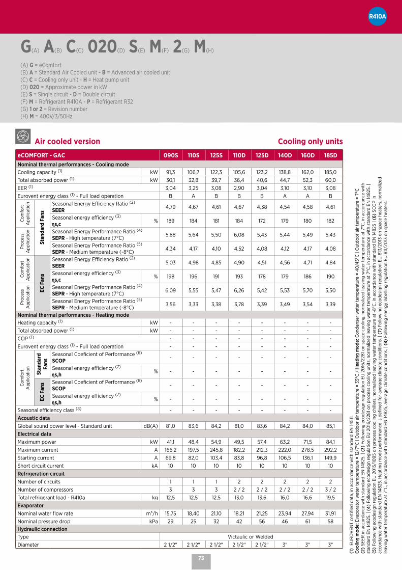
73
Air cooled version Cooling only units
eCOMFORT - GAC 090S 110S 125S 110D 125D 140D 160D 185DNominal thermal performances - Cooling modeCooling capacity (1) kW 91,3 106,7 122,3 105,6 123,2 138,8 162,0 185,0Total absorbed power (1) kW 30,1 32,8 39,7 36,4 40,6 44,7 52,3 60,0EER (1) 3,04 3,25 3,08 2,90 3,04 3,10 3,10 3,08Eurovent energy class (1) - Full load operation B A B B B A A B
Com
fort
A
pplic
atio
n
Stan
dard
Fan
s
Seasonal Energy Efficiency Ratio (2)
SEER 4,79 4,67 4,61 4,67 4,38 4,54 4,58 4,61
Seasonal energy efficiency (3)
s,c % 189 184 181 184 172 179 180 182
Proc
ess
App
licat
ion Seasonal Energy Performance Ratio (4)
SEPR - High temperature (7°C) 5,88 5,64 5,50 6,08 5,43 5,44 5,49 5,43
Seasonal Energy Performance Ratio (5)
SEPR - Medium temperature (-8°C) 4,34 4,17 4,10 4,52 4,08 4,12 4,17 4,08
Com
fort
A
pplic
atio
n
EC F
ans
Seasonal Energy Efficiency Ratio (2)
SEER 5,03 4,98 4,85 4,90 4,51 4,56 4,71 4,84
Seasonal energy efficiency (3)
s,c % 198 196 191 193 178 179 186 190
Proc
ess
App
licat
ion Seasonal Energy Performance Ratio (4)
SEPR - High temperature (7°C) 6,09 5,55 5,47 6,26 5,42 5,53 5,70 5,50
Seasonal Energy Performance Ratio (5)
SEPR - Medium temperature (-8°C) 3,56 3,33 3,38 3,78 3,39 3,49 3,54 3,39
Nominal thermal performances - Heating modeHeating capacity (1) kW - - - - - - - -Total absorbed power (1) kW - - - - - - - -COP (1) - - - - - - - -Eurovent energy class (1) - Full load operation - - - - - - - -
Com
fort
A
pplic
atio
n
Stan
dard
Fa
ns
Seasonal Coeficient of Performance (6)
SCOP - - - - - - - -
Seasonal energy efficiency (7)
s,h % - - - - - - - -
EC F
ans Seasonal Coeficient of Performance (6)
SCOP - - - - - - - -
Seasonal energy efficiency (7)
s,h % - - - - - - - -
Seasonal efficiency class (8) - - - - - - - -Acoustic dataGlobal sound power level - Standard unit dB(A) 81,0 83,6 84,2 81,0 83,6 84,2 84,0 85,1Electrical dataMaximum power kW 41,1 48,4 54,9 49,5 57,4 63,2 71,5 84,1Maximum current A 166,2 197,5 245,8 182,2 212,3 222,0 278,5 292,2Starting current A 69,8 82,0 103,4 83,8 96,8 106,5 136,1 149,9Short circuit current kA 10 10 10 10 10 10 10 10Refrigeration circuitNumber of circuits 1 1 1 2 2 2 2 2Number of compressors 3 3 3 2 / 2 2 / 2 2 / 2 2 / 2 3 / 2Total refrigerant load - R410a kg 12,5 12,5 12,5 13,0 13,6 16,0 16,6 19,5EvaporatorNominal water flow rate m³/h 15,75 18,40 21,10 18,21 21,25 23,94 27,94 31,91Nominal pressure drop kPa 29 25 32 42 56 46 61 58Hydraulic connectionType Victaulic or WeldedDiameter 2 1/2" 2 1/2" 2 1/2" 2 1/2" 2 1/2" 3" 3" 3"
(1)
EUR
OV
ENT
cert
ified
dat
a, in
acc
orda
nce
with
sta
ndar
d EN
1451
1. Co
olin
g m
ode:
Eva
pora
tor w
ater
tem
pera
ture
= 12
/7°C
| O
utdo
or a
ir te
mpe
ratu
re =
35°
C /
Hea
ting
mod
e: C
onde
nser
wat
er te
mpe
ratu
re =
40/
45°C
| O
utdo
or a
ir te
mpe
ratu
re =
7°C
(2
) SE
ER in
acc
orda
nce
with
sta
ndar
d EN
1482
5. |
(3)
Follo
win
g ec
odes
ign
regu
latio
n EU
20
16/2
281 o
n sp
ace
cool
ing,
nor
mal
ized
leav
ing
wat
er te
mpe
ratu
re a
t 7°
C, i
n ac
cord
ance
with
st
anda
rd E
N 14
825.
| (4
) Fo
llow
ing
ecod
esig
n re
gula
tion
EU 2
016
/228
1 on
proc
ess
cool
ing
units
, nor
mal
ized
leav
ing
wat
er te
mpe
ratu
re a
t 7°
C, i
n ac
cord
ance
with
sta
ndar
d EN
1482
5. |
(5)
Follo
win
g ec
odes
ign
regu
latio
n EU
20
15/1
095
on
proc
ess
cool
ing
chill
ers,
nor
mal
ized
leav
ing
wat
er te
mpe
ratu
re a
t -8°
C, i
n ac
cord
ance
with
sta
ndar
d EN
1482
5 | (
6) S
CO
P in
ac
cord
ance
with
sta
ndar
d EN
1482
5. H
eatin
g m
ode
perf
orm
ance
is d
efine
d fo
r av
erag
e cl
imat
e co
nditi
ons.
| (7
) Fo
llow
ing
ecod
esig
n re
gula
tion
EU 8
13/2
013
on
spac
e he
ater
s, n
orm
aliz
ed
leav
ing
wat
er te
mpe
ratu
re a
t 7°
C, i
n ac
cord
ance
with
sta
ndar
d EN
1482
5, a
vera
ge c
limat
e co
nditi
ons.
| (8
) Fo
llow
ing
ener
gy la
belli
ng re
gula
tion
EU 8
11/2
013
on
spac
e he
ater
s.
G(A) A(B) C(C) 020(D) S(E) M(F) 2(G) M(H) (A) G = eComfort(B) A = Standard Air Cooled unit - B = Advanced air cooled unit(C) C = Cooling only unit - H = Heat pump unit(D) 020 = Approximate power in kW(E) S = Single circuit - D = Double circuit(F) M = Refrigerant R410A - P = Refrigerant R32(G) 1 or 2 = Revision number(H) M = 400V/3/50Hz

74
eComfort | Nomenclature and general data
Air cooled version Heat pump units
eCOMFORT - GAH 020S 025S 030S 035S 040S 045S 055S 060S 070S 080SNominal thermal performances - Cooling modeCooling capacity (1) kW 20,0 24,4 31,0 36,4 39,4 44,7 54,0 60,1 68,4 81,4Total absorbed power (1) kW 6,0 8,0 11,2 12,4 13,5 16,2 17,9 20,1 23,1 26,7EER (1) 3,31 3,05 2,77 2,94 2,92 2,76 3,02 2,99 2,96 3,05Eurovent energy class (1) - Full load operation A B C B B C B B B B
Com
fort
A
pplic
atio
n
Stan
dard
Fan
s
Seasonal Energy Efficiency Ratio (2)
SEER 4,67 4,50 4,15 4,28 4,34 4,19 4,53 4,28 4,48 4,52
Seasonal energy efficiency (3)
s,c % 184 177 163 168 170 165 178 168 176 178
Proc
ess
App
licat
ion Seasonal Energy Performance Ratio (4)
SEPR - High temperature (7°C) 7,29 6,77 5,88 6,20 6,38 5,63 6,32 5,67 5,72 5,74
Seasonal Energy Performance Ratio (5)
SEPR - Medium temperature (-8°C) 4,77 4,56 4,26 4,64 4,33 4,01 4,73 4,28 4,29 4,30
Com
fort
A
pplic
atio
n
EC F
ans
Seasonal Energy Efficiency Ratio (2)
SEER 4,67 4,84 4,42 4,64 4,69 4,54 4,79 4,55 4,65 4,77
Seasonal energy efficiency (3)
s,c % 190 197 180 188 190 185 194 185 189 194
Proc
ess
App
licat
ion Seasonal Energy Performance Ratio (4)
SEPR - High temperature (7°C) 7,29 6,76 5,85 6,25 6,52 5,64 6,26 5,55 5,61 5,74
Seasonal Energy Performance Ratio (5)
SEPR - Medium temperature (-8°C) 3,39 3,52 3,51 3,62 346,00 344,00 372,00 360,00 368,00 360,00
Nominal thermal performances - Heating modeHeating capacity (1) kW 19,8 24,5 31,9 36,7 39,2 44,6 53,6 61,3 67,6 79,3Total absorbed power (1) kW 6,6 8,2 10,6 12,2 13,1 14,9 17,9 20,3 21,7 26,0COP (1) 3,00 3,00 3,01 3,00 3,00 3,00 3,00 3,02 3,11 3,05Eurovent energy class (1) - Full load operation B B B B B B B B B B
Com
fort
A
pplic
atio
n Stan
dard
Fa
ns
Seasonal Coeficient of Performance (6)
SCOP 3,45 3,27 3,27 3,35 3,33 3,32 3,39 3,38 3,49 3,51
Seasonal energy efficiency (7)
s,h % 135 128 128 131 130 130 133 132 137 138
EC F
ans Seasonal Coeficient of Performance (6)
SCOP 3,45 3,46 3,37 3,48 3,45 3,43 3,57 3,45 3,57 3,62
Seasonal energy efficiency (7)
s,h % 135 135 132 136 135 134 140 135 140 142
Seasonal efficiency class (8) A+ A+ A+ A+ A+ A+ A+ A+ A+ A+Acoustic dataGlobal sound power level - Standard unit dB(A) 72,4 74,0 74,0 76,4 76,4 75,7 77,8 75,4 79,5 81,0Electrical dataMaximum power kW 9,9 12,2 15,3 17,6 18,2 21,0 25,1 28,0 30,9 35,8Maximum current A 52,1 61,7 88,7 118,0 117,6 147,9 140,6 162,6 167,4 210,5Starting current A 16,6 18,8 25,8 31,2 30,5 37,1 42,2 47,0 51,8 68,1Short circuit current kA 10 10 10 10 10 10 10 10 10 10Refrigeration circuitNumber of circuits 1 1 1 1 1 1 1 1 1 1Number of compressors 2 2 2 2 2 2 2 2 2 2Total refrigerant load - R410a kg 7,0 7,4 8,3 8,8 9,0 9,2 13,5 17,0 18,4 18,4EvaporatorNominal water flow rate m³/h 3,45 4,21 5,35 6,28 6,80 7,71 9,31 10,37 11,80 14,04Nominal pressure drop kPa 17 25 26 35 29 38 32 39 17 24Hydraulic connectionType Threaded male Victaulic or WeldedDiameter 1 1/2" 1 1/2" 1 1/2" 1 1/2" 1 1/2" 1 1/2" 2" 2" 2" 2"
G(A) A(B) C(C) 020(D) S(E) M(F) 2(G) M(H) (A) G = eComfort(B) A = Standard Air Cooled unit - B = Advanced air cooled unit(C) C = Cooling only unit - H = Heat pump unit(D) 020 = Approximate power in kW(E) S = Single circuit - D = Double circuit(F) M = Refrigerant R410A - P = Refrigerant R32(G) 1 or 2 = Revision number(H) M = 400V/3/50Hz

75
Air cooled version Heat pump units
eCOMFORT - GAH 090S 110S 125S 110D 125D 140D 160D 185DNominal thermal performances - Cooling modeCooling capacity (1) kW 90,5 105,6 120,4 104,7 121,0 136,5 159,3 181,4Total absorbed power (1) kW 30,4 33,5 40,8 37,4 41,8 46,2 54,1 62,3EER (1) 2,98 3,15 2,95 2,80 2,90 2,95 2,95 2,91Eurovent energy class (1) - Full load operation B A B C B B B B
Com
fort
A
pplic
atio
n
Stan
dard
Fan
s
Seasonal Energy Efficiency Ratio (2)
SEER 4,76 4,67 4,58 4,60 4,28 4,41 4,49 4,53
Seasonal energy efficiency (3)
s,c % 187 184 180 181 168 173 176 178
Proc
ess
App
licat
ion Seasonal Energy Performance Ratio (4)
SEPR - High temperature (7°C) 5,93 5,63 5,47 6,05 5,39 5,38 5,48 5,37
Seasonal Energy Performance Ratio (5)
SEPR - Medium temperature (-8°C) 4,32 4,18 4,08 4,57 4,04 4,05 4,12 4,05
Com
fort
A
pplic
atio
n
EC F
ans
Seasonal Energy Efficiency Ratio (2)
SEER 4,97 4,93 4,79 4,82 4,47 4,58 4,69 4,75
Seasonal energy efficiency (3)
s,c % 202 200 195 196 182 186 191 193
Proc
ess
App
licat
ion Seasonal Energy Performance Ratio (4)
SEPR - High temperature (7°C) 6,01 5,40 5,36 6,18 5,44 5,41 5,60 5,42
Seasonal Energy Performance Ratio (5)
SEPR - Medium temperature (-8°C) 3,59 3,36 3,39 3,83 3,39 3,48 3,53 3,39
Nominal thermal performances - Heating modeHeating capacity (1) kW 91,2 103,4 118,1 106,3 121,1 135,8 157,2 174,6Total absorbed power (1) kW 30,3 34,1 39,4 34,0 40,2 43,5 51,5 58,5COP (1) 3,01 3,03 3,00 3,13 3,02 3,12 3,05 2,99Eurovent energy class (1) - Full load operation B B B B B B B B
Com
fort
A
pplic
atio
n Stan
dard
Fa
ns
Seasonal Coeficient of Performance (6)
SCOP 3,71 3,58 3,49 3,81 3,49 3,58 3,63 3,38
Seasonal energy efficiency (7)
s,h % 145 140 136 150 137 140 142 132
EC F
ans Seasonal Coeficient of Performance (6)
SCOP 3,76 3,71 3,69 3,84 3,65 3,58 3,74 3,70
Seasonal energy efficiency (7)
s,h % 147 145 145 151 143 140 147 145
Seasonal efficiency class (8) A+ A+ A+ A+ A+ A+ A+ A+Acoustic dataGlobal sound power level - Standard unit dB(A) 81,0 83,6 84,2 81,0 83,6 84,2 84,0 85,1Electrical dataMaximum power kW 41,1 48,4 54,9 49,5 57,4 63,2 71,5 84,1Maximum current A 166,2 197,5 245,8 182,2 212,3 222,0 278,5 292,2Starting current A 69,8 82,0 103,4 83,8 96,8 106,5 136,1 149,9Short circuit current kA 10 10 10 10 10 10 10 10Refrigeration circuitNumber of circuits 1 1 1 2 2 2 2 2Number of compressors 3 3 3 2 / 2 2 / 2 2 / 2 2 / 2 3 / 2Total refrigerant load - R410a kg 25,0 27,0 27,3 27,6 29,0 35,0 37,0 38,0EvaporatorNominal water flow rate m³/h 15,61 18,21 20,77 18,06 20,87 23,54 27,48 31,29Nominal pressure drop kPa 29 25 31 41 54 44 59 56Hydraulic connectionType Victaulic or WeldedDiameter 2 1/2" 2 1/2" 2 1/2" 2 1/2" 2 1/2" 3" 3" 3"
(1)
EUR
OV
ENT
cert
ified
dat
a, in
acc
orda
nce
with
sta
ndar
d EN
1451
1. Co
olin
g m
ode:
Eva
pora
tor w
ater
tem
pera
ture
= 12
/7°C
| O
utdo
or a
ir te
mpe
ratu
re =
35°
C /
Hea
ting
mod
e: C
onde
nser
wat
er te
mpe
ratu
re =
40/
45°C
| O
utdo
or a
ir te
mpe
ratu
re =
7°C
(2
) SE
ER in
acc
orda
nce
with
sta
ndar
d EN
1482
5. |
(3)
Follo
win
g ec
odes
ign
regu
latio
n EU
20
16/2
281 o
n sp
ace
cool
ing,
nor
mal
ized
leav
ing
wat
er te
mpe
ratu
re a
t 7°
C, i
n ac
cord
ance
with
st
anda
rd E
N 14
825.
| (4
) Fo
llow
ing
ecod
esig
n re
gula
tion
EU 2
016
/228
1 on
proc
ess
cool
ing
units
, nor
mal
ized
leav
ing
wat
er te
mpe
ratu
re a
t 7°
C, i
n ac
cord
ance
with
sta
ndar
d EN
1482
5. |
(5)
Follo
win
g ec
odes
ign
regu
latio
n EU
20
15/1
095
on
proc
ess
cool
ing
chill
ers,
nor
mal
ized
leav
ing
wat
er te
mpe
ratu
re a
t -8°
C, i
n ac
cord
ance
with
sta
ndar
d EN
1482
5 | (
6) S
CO
P in
ac
cord
ance
with
sta
ndar
d EN
1482
5. H
eatin
g m
ode
perf
orm
ance
is d
efine
d fo
r av
erag
e cl
imat
e co
nditi
ons.
| (7
) Fo
llow
ing
ecod
esig
n re
gula
tion
EU 8
13/2
013
on
spac
e he
ater
s, n
orm
aliz
ed
leav
ing
wat
er te
mpe
ratu
re a
t 7°
C, i
n ac
cord
ance
with
sta
ndar
d EN
1482
5, a
vera
ge c
limat
e co
nditi
ons.
| (8
) Fo
llow
ing
ener
gy la
belli
ng re
gula
tion
EU 8
11/2
013
on
spac
e he
ater
s.
G(A) A(B) C(C) 020(D) S(E) M(F) 2(G) M(H) (A) G = eComfort(B) A = Standard Air Cooled unit - B = Advanced air cooled unit(C) C = Cooling only unit - H = Heat pump unit(D) 020 = Approximate power in kW(E) S = Single circuit - D = Double circuit(F) M = Refrigerant R410A - P = Refrigerant R32(G) 1 or 2 = Revision number(H) M = 400V/3/50Hz

76
eComfort | Dimensions and weights
Air cooled version Cooling only unitseCOMFORT - GAC 035S 040S 045S 050S 055S 060S 065S 070S 080S
Amm
1125 1125 2250B 1320 1320 1320C 1740 2109 1779Weight of standard unitsBasic unit kg 434 443 449 565 566 583 793 793 843
Air cooled version Heat pump unitseCOMFORT - GAH 035S 040S 045S 050S 055S 060S 065S 070S 080S
Amm
1125 1125 2250B 1320 1320 1320C 1740 2109 1779Weight of standard unitsBasic unit kg 434 443 449 565 566 583 793 793 843
Air cooled version Cooling only unitseCOMFORT - GAC 095S 110S 115S 125S 140S 110D 125D 140D 160D 185D 210D
Amm
2250 2250 2250B 1320 1740 2650C 2071 2071 2071Weight of standard unitsBasic unit kg 679 691 719 868 901 859 895 880 1405 1441 1441
Air cooled version Heat pump unitseCOMFORT - GAH 095S 110S 115S 125S 140S 110D 125D 140D 160D 185D 210D
Amm
2250 2250 2250B 1320 1740 2650C 2071 2071 2071Weight of standard unitsBasic unit kg 679 691 719 868 901 859 895 880 1405 1441 1441
A
C
B

77
eComfort | Dimensions and weights
Air cooled version Cooling only unitseCOMFORT - GAC 020S 025S 030S 035S 040S 045S 055S 060S 070S 080S 090S 110S 125S 110D 125D 140D 160D 185D
Amm
1320 2250 2250 2250 2650B 1125 1320 1320 1740 2250C 1540 1540 1815 1815 1815Weight of standard unitsBasic unit kg 312 319 342 366 371 386 602 627 657 706 876 892 892 989 1000 1401 1508 1575
Air cooled version Heat pump unitseCOMFORT - GAH 020S 025S 030S 035S 040S 045S 055S 060S 070S 080S 090S 110S 125S 110D 125D 140D 160D 185D
Amm
1320 2250 2250 2650B 1125 1320 1740 2250C 1540 1540 1815 1815Weight of standard unitsBasic unit kg 335 341 370 394 400 421 645 683 715 773 927 995 995 1061 1073 1483 1592 1663
C
BA

78
NOTES

NeosysAir cooled chillers / Heat pumps
LENNOX participates in the ECP programme for LCP-HP.
Check ongoing validity of certificate : www.eurovent-certification.com
AIR COOLED 200 - 1000 kW 200 - 500 kW

80
# Flat top, aesthetic grilles and very low unit height (< 2 m) for discrete installation on a roof reducing the requirement for costly cladding solutions around the unit.
# State of the art design with hidden compressors, fans and pump for perfect architectural integration.
# Partial or total heat recovery achieved with two configurations of the desuperheater, that provides free hot water for domestic use.
# Quiet operation with the thermodynamic and hydraulic modules mounted in a soundproofed technical cabinet.
Neosys | Air cooled chillers / Heat pumps
eDRIVE
Variable speed drive pump option, which modulates the water flow through the evaporator and reduces energy costs:# Saves energy consumption especially at part-load conditions
and during off period, reaching up to 75% reduction of the pump consumption.
# Savings on the initial system cost, due to fewer pumps and piping connections than primary-secondary systems.
# Flexibility and accuracy of the pump operation control: smooth start and stop, gradual change of speed, accuracy and stability of control.
# Reduction of the repeated stress on the pump and piping resulting in longer equipment lifetime.
# Elimination of the start-up current thanks to variable frequency drive that controls a gradual pump motor supply.
CASING & DESIGN
# Casing made of white painted galvanised steel.# Flat top that hides the fans and reduces noise level.# Compact design, granted by the V-shaped coils.# All thermodynamic and hydraulic components
are installed inside the box reducing the noise level and protecting them against climatic conditions.
# Electrical panel with top opening provides protection to the service team against rain or snow during commissioning and maintenance operations.
# Aesthetic protection grilles.
Photos and illustrations are not contractual.

81
ACOUSTIC COMFORT
# Quiet operation (standard), achieved with compact design, silent compressors and pumps, and with high-performance propeller fans, all installed in a closed box.
# Active Acoustic Attenuation System with variable fan speed allows progressive adaptation of the unit to the building load while respecting the noise level constraints and the operating limits (as an option).
REMOTE MONITORING
# Connectivity through LennoxHydrocontrol, a user-friendly interface for local supervision of the entire hydraulic system.
# Connectivity through LennoxCloud (LENNOX WEB PORTAL for Multi sites / units).
# BMS through: - LennoxOneWeb. - ADALINK II* (LENNOX WEB SERVER One site / Several
units). - LennoxTouch.* * Check the availability of this feature in your country.
CONTROL
# Climatic electronic controller and intelligent control parameters optimising part-load efficiency.
# Integrated communication solutions offering flexibility (master/slave, Modbus, BACnet or LonWorks®).
# DC Advanced display, equipped with a graphic screen providing access to the main user parameters, with two optional displays:
- Remote Display - Service Display
THERMODYNAMIC SYSTEM
# Multi-scroll compressors, mounted in tandem or trio, to provide the best seasonal efficiencies.
# Aluminium microchannel condenser coil (Cooling only version).
# Variable speed fans with exclusive design with SKF hybrid Ceramic bearings that improves service life and reduces noise level.
# Low water system volume to reduce the time to reach the setpoint.
# Dynamic defrost (patented) to limit the number of defrost cycles.
# Thermally insulated and frost-protected dual circuit water heat exchangers made from stainless steel plates with copper brazing.
# Up to four independent circuits.# Desuperheater (as an option): additional plate
heat exchanger on each circuit to recover the rejected heat and provide free hot water for sanitary or industrial purposes.
# Single or dual pump.

82
N(A) A(B) C(C) 200(D) D(E) N(F) M(G) 7(H) M(I)
(A) N = Neosys(B) A = Air cooled(C) C = Cooling mode - H = Heat pump mode(D) 200 = Cooling capacity in kW(E) Number of circuits - S = 1 circuit - D = 2 circuits - T = 3 circuits - F = 4 circuits(F) N = Non ducted(G) M = R410A refrigerant(H) 7 = Revision number(I) M = 400V/3/50Hz
Neosys | Nomenclature and general data
Air cooled version Cooling only units
Neosys - NAC 200D 230D 270D 300D 340D 380D 420D 480D
Nominal thermal performances - Cooling modeCooling capacity (1) kW 208,2 235,7 272,8 307,6 351,3 387,3 429,6 489,9Total absorbed power (1) kW 72,1 85,7 106,7 106,9 125,6 149,1 152,3 174,3EER (1) 2,89 2,75 2,56 2,88 2,80 2,60 2,82 2,81
Com
fort
A
pplic
atio
n Seasonal Energy Efficiency Ratio (2)
SEER 4,72 4,62 4,36 4,73 4,70 4,57 4,86 4,79
Seasonal energy efficiency (3)
s,c % 186 182 171 186 185 180 191 188
Proc
ess
App
licat
ion Seasonal Energy Performance Ratio (4)
SEPR - High temperature (7°C) 5,53 5,26 5,29 5,51 5,68 5,50 5,65 5,55
Seasonal Energy Performance Ratio (5)
SEPR - Medium temperature (-8°C) 3,88 3,85 3,82 3,82 3,99 3,91 3,92 3,99
Nominal thermal performances - Heating modeHeating capacity (1) kW - - - - - - - -Total absorbed power (1) kW - - - - - - - -COP (1) - - - - - - - -
Com
fort
A
pplic
atio
n Seasonal Coeficient of Performance (6)
SCOP - - - - - - - -
Seasonal energy efficiency (7)
s,h % - - - - - - - -
Seasonal efficiency class (8) - - - - - - - -Acoustic dataGlobal sound power level - Standard unit dB(A) 89,2 89,3 89,7 91,2 91,3 91,4 92,5 92,6Electrical dataMaximum power kW 96,7 113,7 135,0 147,1 166,2 191,7 205,9 231,4Maximum current A 169,6 199,0 225,0 247,3 277,2 321,3 344,1 388,2Starting current A 397,0 449,7 475,7 498,0 527,9 572,0 594,8 638,9Short circuit current kA 10 10 50 50 50 50 50 50Refrigeration circuitNumber of circuits 2 2 2 2 2 2 2 2Number of compressors 4 4 4 4 5 5 6 6Total refrigerant load - R410a kg 25,6 25,5 29,3 35,2 37,1 39,0 52,4 55,3EvaporatorNominal water flow rate m³/h 35,80 40,60 46,90 52,90 60,40 66,60 73,90 84,30Nominal pressure drop kPa 43 54 56 48 35 42 50 49Hydraulic connectionType VictaulicDiameter 4" 4" 4" 4" 5" 5" 5" 5"
(1) EUROVENT certified data, in accordance with standard EN 14511. Cooling mode: Evaporator water temperature = 12/7°C | Outdoor air temperature = 35°C / Heating mode: Condenser water temperature = 40/45°C | Outdoor air temperature = 7°C (2) SEER in accordance with standard EN 14825. | (3) Following ecodesign regulation EU 2016/2281 on space cooling, normalized leaving water temperature at 7°C, in accordance with standard EN 14825. | (4) Following ecodesign regulation EU 2016/2281 on process cooling units, normalized leaving water temperature at 7°C, in accordance with standard EN 14825. | (5) Following ecodesign regulation EU 2015/1095 on process cooling chillers, normalized leaving water temperature at -8°C, in accordance with standard EN 14825. | (6) SCOP in accordance with standard EN 14825. Heating mode performance is defined for average climate conditions. | (7) Following ecodesign regulation EU 813/2013 on space heaters, normalized leaving water temperature at 7°C, in accordance with standard EN 14825, average climate conditions. | (8) Following energy labelling regulation EU 811/2013 on space heaters.

83
N(A) A(B) C(C) 200(D) D(E) N(F) M(G) 7(H) M(I)
(A) N = Neosys(B) A = Air cooled(C) C = Cooling mode - H = Heat pump mode(D) 200 = Cooling capacity in kW(E) Number of circuits - S = 1 circuit - D = 2 circuits - T = 3 circuits - F = 4 circuits(F) N = Non ducted(G) M = R410A refrigerant(H) 7 = Revision number(I) M = 400V/3/50Hz
Air cooled version Cooling only units
Neosys - NAC 540D 600D 640D 680F 760F 840F 960F 1080F
Nominal thermal performances - Cooling modeCooling capacity (1) kW 530,9 605,0 626,9 702,6 774,7 859,1 979,8 1061,9Total absorbed power (1) kW 201,9 219,1 226,1 251,3 298,2 304,6 348,7 403,8EER (1) 2,63 2,76 2,77 2,80 2,60 2,82 2,81 2,63
Com
fort
A
pplic
atio
n Seasonal Energy Efficiency Ratio (2)
SEER 4,62 4,59 4,60 4,63 4,55 4,84 4,78 4,60
Seasonal energy efficiency (3)
s,c % 182 181 181 182 179 191 188 181
Proc
ess
App
licat
ion Seasonal Energy Performance Ratio (4)
SEPR - High temperature (7°C) 5,52 5,51 5,50 5,68 5,51 5,65 5,55 5,50
Seasonal Energy Performance Ratio (5)
SEPR - Medium temperature (-8°C) 3,81 4,04 4,06 3,95 3,86 3,88 3,95 3,92
Nominal thermal performances - Heating modeHeating capacity (1) kW - - - - - - - -Total absorbed power (1) kW - - - - - - - -COP (1) - - - - - - - -
Com
fort
A
pplic
atio
n Seasonal Coeficient of Performance (6)
SCOP - - - - - - - -
Seasonal energy efficiency (7)
s,h % - - - - - - - -
Seasonal efficiency class (8) - - - - - - - -Acoustic dataGlobal sound power level - Standard unit dB(A) 93,0 94,0 94,0 94,3 94,4 95,5 95,6 96,0Electrical dataMaximum power kW 258,1 288,4 288,4 2 x 166,2 2 x 191,7 2 x 205,9 2 x 231,4 2 x 258,1Maximum current A 431,7 482,8 482,8 2 x 277,23 2 x 321,3 2 x 344,13 2 x 388,2 2 x 431,7Starting current A 765,9 817,0 817,0 2 x 527,93 2 x 572 2 x 594,83 2 x 638,9 2 x 765,9Short circuit current kA 50 50 50 50 50 50 50 50Refrigeration circuitNumber of circuits 2 2 2 4 4 4 4 4Number of compressors 6 6 6 10 10 12 12 12Total refrigerant load - R410a kg 59,8 73,4 69,0 74,2 78,0 104,8 110,6 119,6EvaporatorNominal water flow rate m³/h 91,30 104,10 107,90 120,90 133,30 147,80 168,60 182,70Nominal pressure drop kPa 57 59 58 57 51 56 66 71Hydraulic connectionType VictaulicDiameter 6" 6" 6" 8" 8" 8" 8" 8"
(1) EUROVENT certified data, in accordance with standard EN 14511. Cooling mode: Evaporator water temperature = 12/7°C | Outdoor air temperature = 35°C / Heating mode: Condenser water temperature = 40/45°C | Outdoor air temperature = 7°C (2) SEER in accordance with standard EN 14825. | (3) Following ecodesign regulation EU 2016/2281 on space cooling, normalized leaving water temperature at 7°C, in accordance with standard EN 14825. | (4) Following ecodesign regulation EU 2016/2281 on process cooling units, normalized leaving water temperature at 7°C, in accordance with standard EN 14825. | (5) Following ecodesign regulation EU 2015/1095 on process cooling chillers, normalized leaving water temperature at -8°C, in accordance with standard EN 14825. | (6) SCOP in accordance with standard EN 14825. Heating mode performance is defined for average climate conditions. | (7) Following ecodesign regulation EU 813/2013 on space heaters, normalized leaving water temperature at 7°C, in accordance with standard EN 14825, average climate conditions. | (8) Following energy labelling regulation EU 811/2013 on space heaters.

84
N(A) A(B) C(C) 200(D) D(E) N(F) M(G) 7(H) M(I)
(A) N = Neosys(B) A = Air cooled(C) C = Cooling mode - H = Heat pump mode(D) 200 = Cooling capacity in kW(E) Number of circuits - S = 1 circuit - D = 2 circuits - T = 3 circuits - F = 4 circuits(F) N = Non ducted(G) M = R410A refrigerant(H) 7 = Revision number(I) M = 400V/3/50Hz
Neosys | Nomenclature and general data
Air cooled version Heat pump unitsNeosys - NAH 200D 230D 270D 300D 340D 380D 420D 480D
Nominal thermal performances - Cooling modeCooling capacity (1) kW 191,0 217,0 265,9 295,4 323,6 360,9 398,5 442,2Total absorbed power (1) kW 73,5 92,7 104,7 117,1 131,8 133,4 159,1 183,5EER (1) 2,60 2,34 2,54 2,52 2,46 2,71 2,50 2,41
Com
fort
A
pplic
atio
n Seasonal Energy Efficiency Ratio (2)
SEER 4,23 4,10 4,40 4,30 4,45 4,80 4,66 4,63
Seasonal energy efficiency (3)
s,c % 166 161 173 169 175 189 183 182
Proc
ess
App
licat
ion Seasonal Energy Performance Ratio (4)
SEPR - High temperature (7°C) 5,35 5,02 5,29 5,25 5,40 5,42 5,27 5,12
Seasonal Energy Performance Ratio (5)
SEPR - Medium temperature (-8°C) - - - - - - - -
Nominal thermal performances - Heating modeHeating capacity (1) kW 218,5 234,9 290,8 339,0 363,3 404,5 452,5 499,2Total absorbed power (1) kW 71,7 84,0 104,3 112,7 121,3 132,9 151,7 169,5COP (1) 3,05 2,80 2,79 3,01 3,00 3,04 2,98 2,95
Com
fort
A
pplic
atio
n Seasonal Coeficient of Performance (6)
SCOP 3,44 3,32 3,39 3,45 3,47 3,39 3,33 3,35
Seasonal energy efficiency (7)
s,h % 134 130 132 135 136 132 130 131
Seasonal efficiency class (8) A+ A+ A+ A+ A+ A+ A+ A+Acoustic dataGlobal sound power level - Standard unit dB(A) 89,2 89,3 91,1 91,2 91,3 92,4 91,5 91,6Electrical dataMaximum power kW 96,7 113,7 138,6 155,6 166,2 180,4 205,9 231,4Maximum current A 169,6 199,0 232,6 262,0 277,2 300,1 344,1 388,2Starting current A 397,0 449,7 483,3 512,7 527,9 527,4 594,8 638,9Short circuit current kA 10 10 50 50 50 50 50 50Refrigeration circuitNumber of circuits 2 2 2 2 2 2 2 2Number of compressors 4 4 4 4 5 6 6 6Total refrigerant load - R410a kg 52,0 52,0 81,0 81,0 83,0 102,0 102,0 104,0EvaporatorNominal water flow rate m³/h 33,07 37,52 45,60 51,29 55,96 62,29 68,46 76,88Nominal pressure drop kPa 37 47 53 51 28 34 41 36Hydraulic connectionType VictaulicDiameter 4" 4" 4" 4" 5" 5" 5" 5"
(1) EUROVENT certified data, in accordance with standard EN 14511. Cooling mode: Evaporator water temperature = 12/7°C | Outdoor air temperature = 35°C / Heating mode: Condenser water temperature = 40/45°C | Outdoor air temperature = 7°C (2) SEER in accordance with standard EN 14825. | (3) Following ecodesign regulation EU 2016/2281 on space cooling, normalized leaving water temperature at 7°C, in accordance with standard EN 14825. | (4) Following ecodesign regulation EU 2016/2281 on process cooling units, normalized leaving water temperature at 7°C, in accordance with standard EN 14825. | (5) Following ecodesign regulation EU 2015/1095 on process cooling chillers, normalized leaving water temperature at -8°C, in accordance with standard EN 14825. | (6) SCOP in accordance with standard EN 14825. Heating mode performance is defined for average climate conditions. | (7) Following ecodesign regulation EU 813/2013 on space heaters, normalized leaving water temperature at 7°C, in accordance with standard EN 14825, average climate conditions. | (8) Following energy labelling regulation EU 811/2013 on space heaters.

85
Sizes 200 to 640
Sizes 680 to 1080
Neosys | Dimensions and weights
Air cooled version Cooling only units
Neosys - NAC 200D 230D 270D 300D 340D 380D 420D 480D 540D 600D 640D 680F 760F 840F 960F 1080F
Amm
3593 4623 5653 6683 9040 11100B 2280 2280 2280 2280 2280 2280C 2025 2025 2025 2025 1965 1965Weight of standard unitsBasic unit kg 1983 2011 2278 2676 3003 3045 3580 3661 3712 4152 4175 6770 6854 7981 8141 8229
Air cooled version Heat pump unitsNeosys - NAH 200D 230D 270D 300D 340D 380D 420D 480D
Amm
3593 4518 5548B 2280 2280 2280C 2025 2025 2025Weight of standard unitsBasic unit kg 2176 2175 2906 3380 3349 4020 4066 4148

86
NOTES

EcoleanAir cooled chillers / Heat pumps
LLENNOX participates in the ECP programme for LCP-HP.
Check ongoing validity of certificate : www.eurovent-certification.com
AIR COOLED 40 - 200 kW 50 - 200 kW

88
# Designed with the latest technologies to ensure high energy performance all year long.
# Two basic models available, one for outdoor installation and another for indoor installation with ducted air flow on the condenser (fans designed for high available static pressure).
# Compact solution for all air conditioning applications in light commercial buildings.
# Two options for integrated hydraulic module for plug & play installation.
Ecolean | Air cooled chillers / Heat pumps
CASING & DESIGN
# Casing made of powder coated galvanised steel, with rigid, hot dipped galvanised chassis.
# Side grilles as an option to protect the unit during transportation and prevent accidental damage.
CONTROL
# Climatic 60 electronic controller and intelligent control parameters optimising part-load efficiency.
# Integrated communication solutions offering flexibility (master/slave, Modbus, BACnet or LonWorks®).
# DC Advanced display, equipped with a graphic screen providing access to the main user parameters, with two optional displays:
- DC60 Customer Display (also available as remote display) - DS60 Service Display
eDRIVE
Variable speed drive pump option, which modulates the water flow through the evaporator and reduces energy costs:# Saves energy consumption especially at part-load
conditions and during off period, reaching up to 75% reduction of the pump consumption.
# Savings on the initial system cost, due to fewer pumps and piping connections than primary-secondary systems.
# Flexibility and accuracy of the pump operation control: smooth start and stop, gradual change of speed, accuracy and stability of control.
# Reduction of the repeated stress on the pump and piping resulting in longer equipment lifetime.
# Elimination of the start-up current thanks to variable frequency drive that controls a gradual pump motor supply.
CLIMATIC 60 DS60 DC60

89
THERMODYNAMIC SYSTEM
# Multi-scroll compressors, allowing capacity modulation.# High performance outdoor coil.# High performance fans to improve efficiency and
reduce noise level (EC version available as an option).# Thermostatic expansion valves.# Insulated brazed plate heat exchangers made with
stainless steel.# Up to two independent circuits, each equipped with
thermostatic expansion valves.
WATER CIRCUIT
# Water flow switch.# Water filter.# Hydraulic module with single pump and all necessary hydraulic
devices (HY version).# Hydraulic module with single pump, buffer tank and all necessary
hydraulic devices (HN version).# Twin pump as an option with operating time equalisation and
automatic change-over in case of a pump fault.# Variable speed pump as an option to reduce annual pumping
energy consumption based on a constant delta P or a constant delta T management.
ACOUSTIC COMFORT
Two different noise level configurations available:# Low noise version (LN): average reduction of
7 dB(A) thanks to a fan running in low speed and compressor insulated in a high performance acoustic jacket.
# Super low noise version (SLN): average reduction of 10 dB(A) thanks to a fan running in low speed and compressor insulated in a very high performance acoustic cabinet.
Photos and illustrations are not contractual.

90
E(A) A(B) C(C) 100(D) 3(E) S(F) M(G) 4(H) HN(I) LN(J)
(A) E = EcoleanTM(B) A = Air cooled(C) C = Cooling only - R = Reversible heat pump(D) 100 = Cooling capacity in kW(E) 3 = Number of compressors(F) S = Standard version - F = Fan pressure version(G) M = R410A refrigerant(H) 4 = Revision number(I) -- = Basic - HY = Hydraulic (pump) - HN = Hydronic (pump + buffer tank)(J) -- = Standard - LN = Low noise - SLN = Super low noise
Ecolean | Nomenclature and general data
Air cooled version Cooling only units
Ecolean - EAC 472 552 672 812 1003 1103 1203 1303 1403 1604 1804 2104
Nominal thermal performances - Cooling modeCooling capacity (1) kW 44,1 50,7 63,4 75,4 88,2 102,4 111,8 125,7 138,8 149,2 174,0 199,0Total absorbed power (1) kW 15,2 18,1 22,4 26,8 31,2 35,3 40,1 43,9 48,3 54,1 60,0 71,0EER (1) 2,90 2,79 2,83 2,82 2,83 2,90 2,79 2,86 2,87 2,76 2,90 2,80
Com
fort
A
pplic
atio
n Seasonal Energy Efficiency Ratio (2)
SEER 4,22 4,21 4,16 4,20 4,20 4,16 4,11 4,11 4,14 4,12 4,22 4,11
Seasonal energy efficiency (3)
s,c % 166 166 163 165 165 163 161 162 163 162 166 161
Proc
ess
App
licat
ion Seasonal Energy Performance Ratio (4)
SEPR - High temperature (7°C) 6,27 6,10 5,49 5,38 5,65 5,34 5,05 5,08 5,16 5,20 5,64 5,43
Seasonal Energy Performance Ratio (5)
SEPR - Medium temperature (-8°C) 3,32 3,44 3,36 3,37 3,63 3,45 3,33 3,58 3,65 3,63 3,69 3,66
Nominal thermal performances - Heating modeHeating capacity (1) kW - - - - - - - - - - - -Total absorbed power (1) kW - - - - - - - - - - - -COP (1) - - - - - - - - - - - -
Com
fort
A
pplic
atio
n Seasonal Coeficient of Performance (6)
SCOP - - - - - - - - - - - -
Seasonal energy efficiency (7)
s,h % - - - - - - - - - - - -
Seasonal efficiency class (8) - - - - - - - - - - - -Acoustic dataGlobal sound power level - Standard unit dB(A) 79,0 79,0 80,0 81,0 80,5 82,5 84,8 86,8 87,0 84,7 86,8 89,6Electrical dataMaximum power kW 21,8 25,8 31,6 35,9 42,5 49,3 54,9 61 65,3 71,5 82,4 96,5Maximum current A 130,5 141,5 168,3 209,4 218,3 229,7 280,7 329,5 343,8 277,4 333,8 396,2Starting current A 36,1 43,2 52,8 67,1 75,9 87,3 92,2 102,1 116,4 135 145,3 168,8Short circuit current kA 10 10 10 10 10 10 10 10 10 10 10 10Refrigeration circuitNumber of circuits 1 1 1 1 2 2 2 2 2 2 2 2Number of compressors 2 2 2 2 3 3 3 3 3 4 4 4Total refrigerant load - R410a kg 11,0 12,2 15,5 19,5 23,5 26,0 27,0 30,0 33,7 36,2 45,0 47,0EvaporatorNominal water flow rate m³/h 7,64 8,74 10,86 13,06 15,17 17,55 19,24 21,63 24,10 25,83 29,76 34,01Nominal pressure drop kPa 49 56 75 87 40 43 51 64 79 62 67 90Hydraulic connectionType Threaded - Female Flange
Diameter 2" 2" 2" 2" 2 1/2" 2 1/2" 2 1/2" 2 1/2" 2 1/2" 3" (DN80)
3" (DN80)
3" (DN80)
(1) EUROVENT certified data, in accordance with standard EN 14511. Cooling mode: Evaporator water temperature = 12/7°C | Outdoor air temperature = 35°C / Heating mode: Condenser water temperature = 40/45°C | Outdoor air temperature = 7°C (2) SEER in accordance with standard EN 14825. | (3) Following ecodesign regulation EU 2016/2281 on space cooling, normalized leaving water temperature at 7°C, in accordance with standard EN 14825. | (4) Following ecodesign regulation EU 2016/2281 on process cooling units, normalized leaving water temperature at 7°C, in accordance with standard EN 14825. | (5) Following ecodesign regulation EU 2015/1095 on process cooling chillers, normalized leaving water temperature at -8°C, in accordance with standard EN 14825. | (6) SCOP in accordance with standard EN 14825. Heating mode performance is defined for average climate conditions. | (7) Following ecodesign regulation EU 813/2013 on space heaters, normalized leaving water temperature at 7°C, in accordance with standard EN 14825, average climate conditions. | (8) Following energy labelling regulation EU 811/2013 on space heaters.

91
E(A) A(B) C(C) 100(D) 3(E) S(F) M(G) 4(H) HN(I) LN(J)
(A) E = EcoleanTM(B) A = Air cooled(C) C = Cooling only - R = Reversible heat pump(D) 100 = Cooling capacity in kW(E) 3 = Number of compressors(F) S = Standard version - F = Fan pressure version(G) M = R410A refrigerant(H) 4 = Revision number(I) -- = Basic - HY = Hydraulic (pump) - HN = Hydronic (pump + buffer tank)(J) -- = Standard - LN = Low noise - SLN = Super low noise
Air cooled version Heat pump units
Ecolean - EAR 472 552 672 812 1003 1103 1203 1303 1403 1604 1804 2104
Nominal thermal performances - Cooling modeCooling capacity (1) kW 44,1 50,7 63,4 75,4 88,2 102,4 111,8 125,7 138,8 149,2 174,0 199,0Total absorbed power (1) kW 15,2 18,1 22,4 26,8 31,2 35,3 40,1 43,9 48,3 54,1 60,0 71,0EER (1) 2,90 2,79 2,83 2,82 2,83 2,90 2,79 2,86 2,87 2,76 2,90 2,80
Com
fort
A
pplic
atio
n Seasonal Energy Efficiency Ratio (2)
SEER 4,22 4,21 4,16 4,20 4,20 4,16 4,11 4,11 4,14 4,12 4,22 4,11
Seasonal energy efficiency (3)
s,c % 166 166 163 165 165 163 161 162 163 162 166 161
Proc
ess
App
licat
ion Seasonal Energy Performance Ratio (4)
SEPR - High temperature (7°C) 6,27 6,10 5,49 5,38 5,65 5,34 5,05 5,08 5,16 5,20 5,64 5,43
Seasonal Energy Performance Ratio (5)
SEPR - Medium temperature (-8°C) 3,70 3,93 3,71 3,65 3,66 3,46 3,34 3,30 3,41 3,37 3,43 3,17
Nominal thermal performances - Heating modeHeating capacity (1) kW 47,8 54,8 68,0 75,7 95,0 107,8 118,2 130,4 142,5 158,7 179,4 205,0Total absorbed power (1) kW 15,9 18,6 22,7 26,0 31,1 35,9 39,3 44,6 47,9 52,8 60,7 71,8COP (1) 3,0 3,0 3,0 2,9 3,1 3,0 3,0 2,9 3,0 3,0 3,0 2,9
Com
fort
A
pplic
atio
n Seasonal Coeficient of Performance (6)
SCOP 3,2 3,2 3,2 3,2 3,2 3,2 3,2 3,2 3,2 3,2 3,2 3,2
Seasonal energy efficiency (7)
s,h % 126 126 126 126 126 126 126 126 126 126 126 126
Seasonal efficiency class (8) A+ A+ A+ A+ A+ A+ A+ A+ A+ A+ A+ A+Acoustic dataGlobal sound power level - Standard unit dB(A) 79,0 79,0 80,0 81,0 80,5 82,5 84,8 86,8 87,0 84,7 86,8 89,6Electrical dataMaximum power kW 21,8 25,8 31,6 35,9 42,5 49,3 54,9 61 65,3 71,5 82,4 96,5Maximum current A 130,5 141,5 168,3 209,4 218,3 229,7 280,7 329,5 343,8 277,4 333,8 396,2Starting current A 36,1 43,2 52,8 67,1 75,9 87,3 92,2 102,1 116,4 135 145,3 168,8Short circuit current kA 10 10 10 10 10 10 10 10 10 10 10 10Refrigeration circuitNumber of circuits 1 1 1 1 2 2 2 2 2 2 2 2Number of compressors 2 2 2 2 3 3 3 3 3 4 4 4Total refrigerant load - R410a kg 12,5 13,5 16,0 19,3 23,3 28,0 29,5 32,2 35,5 40,0 52,0 54,0EvaporatorNominal water flow rate m³/h 7,64 8,74 10,86 13,06 15,17 17,55 19,24 21,63 24,10 25,83 29,76 34,01Nominal pressure drop kPa 49 56 75 87 40 43 51 64 79 62 67 90Hydraulic connectionType Threaded - Female Flange
Diameter 2" 2" 2" 2" 2 1/2" 2 1/2" 2 1/2" 2 1/2" 2 1/2" 3" (DN80)
3" (DN80)
3" (DN80)
(1) EUROVENT certified data, in accordance with standard EN 14511. Cooling mode: Evaporator water temperature = 12/7°C | Outdoor air temperature = 35°C / Heating mode: Condenser water temperature = 40/45°C | Outdoor air temperature = 7°C (2) SEER in accordance with standard EN 14825. | (3) Following ecodesign regulation EU 2016/2281 on space cooling, normalized leaving water temperature at 7°C, in accordance with standard EN 14825. | (4) Following ecodesign regulation EU 2016/2281 on process cooling units, normalized leaving water temperature at 7°C, in accordance with standard EN 14825. | (5) Following ecodesign regulation EU 2015/1095 on process cooling chillers, normalized leaving water temperature at -8°C, in accordance with standard EN 14825. | (6) SCOP in accordance with standard EN 14825. Heating mode performance is defined for average climate conditions. | (7) Following ecodesign regulation EU 813/2013 on space heaters, normalized leaving water temperature at 7°C, in accordance with standard EN 14825, average climate conditions. | (8) Following energy labelling regulation EU 811/2013 on space heaters.

92
Ecolean | Dimensions and weights
Air cooled version Cooling only & Heat pump units
Ecolean EAC / EAR 472 552 672 812 1003 1103 1203 1303 1403 1604 1804 2104
Amm
1960 2250 2250B 1195 1420 2300C 1616 2128 2227Weight of standard unitsBasic unit - Cooling only (EAC)
kg470 482 518 562 640 809 938 990 1019 1328 1683 1703
Basic unit - Heat Pump (EAR) 480 492 534 578 663 831 964 1016 1045 1347 1703 1723
C
B
A

Aqua4Polyvalent air cooled heat pumps
AIR COOLED 50 - 300 kW 50 - 350 kW

94
# Simultaneous and independent cooling and heating for air conditioning in the most efficient way.
# Constantly balanced heating and cooling needs to obtain maximum Total Efficiency Ratio.
# 100% heat recovery at any condition.
# 4-pipe version with two independent circuits that provides hot and cold water at the same time.
# 2-pipe version with an independent cooling or heating circuit and a dedicated hot sanitary water circuit.
Aqua⁴ | Polyvalent air cooled heat pumps
CASING & DESIGN
# Casing and base frame made of powder coated galvanised steel.
# Ventilated electrical control panel.# Victaulic connections.# Paddle water flow switch.# Fully accessible unit with removable panels.# All thermodynamic components installed inside the box.
DEFROST WITHOUT IMPACTING COMFORT
# Hydrophilic treatment on coil.# Dynamic control on defrost.# Circuits defrost completely independently.# Integrated water tank up to 765 litres.
SECURED OPERATING MAP
# Winter cooling operation down to -15°C ambient.
# Heating operation down to -10°C ambient with 45°C outlet water temperature.
# Heat recovery or production of hot water temperature from 25°C to 55°C.
Photos and illustrations are not contractual.

95
QUIETER UNIT
# Standard version with 8 dB(A) noise level reduction vs traditional heat pumps.
# Low noise version with additional noise level reduction of 12 dB(A).# Innovative hybrid structure of fan blades.# Sound proof cabinet enclosing all components to reduce radiated
sound level.
CONTROL
# Climatic 60 electronic controller and intelligent control parameters optimising part-load efficiency.
# Integrated communication solutions offering flexibility (master/slave, Modbus, BACnet or LonWorks®).
# DC Advanced display, equipped with a graphic screen providing access to the main user parameters, with two optional displays:
- Remote Display - Service Display
THERMODYNAMIC SYSTEM
# High efficiency scroll compressors.# High efficiency brazed plate heat
exchangers.# Copper tubes and aluminium fins coils
with hydrophilic coating.# Axial fans with innovative hybrid
structure of blades (EC version available as an option).
# Insulated brazed plate heat exchangers made with austenitic stainless steel AISI 316, with AISI 316L connections.
# Two independent circuits, each equipped with thermostatic expansion valves.
DC Advanced CLIMATIC 60

96
A(A) A(B) H(C) 08(D) 1(E) M(F) S(G)
(A) A = Aqua4
(B) A = Air cooled(C) H = Heat pump(D) 08 = Nominal cooling capacity x10 [kW] (ex.: 08 = 80kW)(E) 1 = 2 compressors / 2 circuits - 4 = 4 compressors / 2 circuits(F) M = 2 pipes - P = 4 pipes(G) S = Standard noise level - L = Low noise level
Aqua⁴ | Nomenclature and general data
Air cooled version Heat pump units
AQUA⁴ - 2 pipes version
AA
H0
41M
S
AA
H0
51M
S
AA
H0
61M
S
AA
H07
1MS
AA
H0
81M
S
AA
H0
81M
S
AA
H10
4MS
AA
H12
4MS
Nominal thermal performances - Cooling modeCooling capacity (1) kW 49,5 55,0 64,5 72,0 80,8 98,4 109,0 125,4Total absorbed power (1) kW 15,8 18,0 20,1 23,3 26,5 32,1 36,6 39,8EER (1) 3,13 3,05 3,21 3,09 3,04 3,07 2,98 3,15Nominal water flow rate l/h 8499 9437 11075 12361 13875 16901 18716 21534Nominal pressure drop kPa 27 32 31 39 31 35 42 39Nominal thermal performances - Heating modeHeating capacity (1) kW 49,8 56,1 66,8 72,0 80,5 98,1 110,6 124,2Total absorbed power (1) kW 17,7 20,0 22,5 25,8 28,4 35,5 40,0 43,5COP (1) 2,81 2,81 2,97 2,80 2,83 2,76 2,76 2,86Nominal water flow rate l/h 8648 9743 11612 12521 13982 17046 19214 21580Nominal pressure drop kPa 28 34 35 41 32 36 45 40Seasonal Coeficient of Performance - SCOP (2) 3,43 3,4 3,49 3,44 3,47 3,57 3,64 3,83Seasonal energy efficiency - s,h (3) % 134,2 133,0 136,6 134,6 135,8 139,8 142,6 150,2Seasonal efficiency class - L.T. Heat Pump (4) A+ A+ A+ A+ A+ A+ A+ A++Nominal thermal performances - Cooling mode with Domestic Hot WaterCooling capacity (5) kW 47,3 52,9 61,4 69,3 79,6 94,9 106,5 122Heating capacity (5) kW 61,8 69,3 79,5 90,3 103 123,8 139,3 158,3Total absorbed power (5) kW 15,2 17,3 19 22,1 24,6 30,4 34,5 38,2Nominal water flow rate - Cooling circuit l/h 8128 9088 10546 11893 13662 16298 18295 20950Nominal pressure drop - Cooling circuit kPa 25 30 29 36 30 32 40 38Nominal water flow rate - Heating circuit l/h 10734 12051 13813 15685 17892 21511 24211 27515Nominal pressure drop - Heating circuit kPa 41 50 48 61 50 55 68 63Total Efficiency Ratio - TER 7,18 7,07 7,41 7,22 7,41 7,19 7,12 7,33Acoustic dataSound power level dB(A) 80 80 81 81 81 82 82 79Sound pressure level (6) dB(A) 48 48 49 49 49 50 50 47Electrical dataMaximum power kW 25,0 27,0 32,0 36,0 40,0 49,0 55,0 63,0Maximum current A 41 44 51 55 66 81 87 96Starting current A 159 162 185 183 191 194 198 220Short circuit current (automatic breakers / fuse) kA 2,5 / 2,5 2,5 / 2,5 2,5 / 2,5 2,5 / 2,5 2,5 / 2,5 6 / 8 6 / 8 6 / 8
Refrigeration circuitNumber of circuits 2 2 2 2 2 2 2 2Number of compressors 2 2 2 2 2 4 4 4Total refrigerant load - R410a kg 23 23 25,2 26 26 37 38 60Hydraulic connectionType VictaulicDiameter 2" 2" 2" 2" 2" 2 1/2" 2 1/2" 3"
(1) EUROVENT certified data, in accordance with standard EN 14511. Cooling mode: Evaporator water temperature = 12/7°C | Outdoor air temperature = 35°C / Heating mode: Condenser water temperature = 40/45°C | Outdoor air temperature = 7°C (2) SCOP in accordance with standard EN 14825. Heating mode performance is defined for average climate conditions. | (3) Following ecodesign regulation EU 813/2013 on space heaters, normalized leaving water temperature at 7°C, in accordance with standard EN 14825, average climate conditions. | (4) Following energy labelling regulation EU 811/2013 on space heaters. | (5) Cooling at 12/7°C and Heating at 40/45°C. | (6) Sound power level and sound pressure level at 10 m from the unit, in free field, conformity with ISO3744 norm.

97
A(A) A(B) H(C) 08(D) 1(E) M(F) S(G)
(A) A = Aqua4
(B) A = Air cooled(C) H = Heat pump(D) 08 = Nominal cooling capacity x10 [kW] (ex.: 08 = 80kW)(E) 1 = 2 compressors / 2 circuits - 4 = 4 compressors / 2 circuits(F) M = 2 pipes - P = 4 pipes(G) S = Standard noise level - L = Low noise level
Air cooled version Heat pump units
AQUA⁴ - 2 pipes version
AA
H14
4MS
AA
H16
4MS
AA
H19
4MS
AA
H21
4MS
AA
H24
4MS
AA
H27
4MS
AA
H29
4MS
AA
H32
4MS
Nominal thermal performances - Cooling modeCooling capacity (1) kW 139,5 160,8 185,2 207,8 225,6 254,2 281,1 303,3Total absorbed power (1) kW 46,5 53,5 64,8 75,4 84,4 90,8 105,8 121,6EER (1) 3,00 3,00 2,86 2,76 2,67 2,80 2,66 2,50Nominal water flow rate l/h 23957 27622 31808 35684 38742 43651 48273 52094Nominal pressure drop kPa 49 46 43 53 52 36 43 59Nominal thermal performances - Heating modeHeating capacity (1) kW 139,9 167,1 194,0 212,7 232,7 256,0 286,5 316,6Total absorbed power (1) kW 50,1 58,6 67,7 78,0 84,6 93,1 104,3 117,1COP (1) 2,79 2,85 2,87 2,73 2,75 2,75 2,75 2,70Nominal water flow rate l/h 24306 29047 33719 36966 40439 44497 49796 55014Nominal pressure drop kPa 51 51 48 58 57 46 56 67Seasonal Coeficient of Performance - SCOP (2) 3,85 3,55 3,67 3,62 3,68 3,62 3,55 3,55Seasonal energy efficiency - s,h (3) % 151,0 139,0 143,8 141,8 144,2 141,8 139,0 139,0Seasonal efficiency class - L.T. Heat Pump (4) A++ A+ A+ A+ A+ A+ A+ A+Nominal thermal performances - Cooling mode with Domestic Hot WaterCooling capacity (5) kW 137,4 157 185,9 211,1 234,3 258,9 293,8 324,5Heating capacity (5) kW 179,6 204,2 241,5 275,9 305,3 335,9 381,5 423,8Total absorbed power (5) kW 44,4 49,6 58,6 68,2 74,8 81 92,3 104,6Nominal water flow rate - Cooling circuit l/h 23599 26964 31921 36253 40230 44463 50449 55719Nominal pressure drop - Cooling circuit kPa 48 44 43 55 56 38 46 67Nominal water flow rate - Heating circuit l/h 31206 35480 41974 47944 53055 58376 66300 73660Nominal pressure drop - Heating circuit kPa 80 73 71 92 92 75 94 113Total Efficiency Ratio - TER 7,15 7,28 7,3 7,14 7,22 7,34 7,31 7,15Acoustic dataSound power level dB(A) 79 85 85 86 86 86 87 87Sound pressure level (6) dB(A) 47 53 53 54 54 54 55 55Electrical dataMaximum power kW 70,0 78,0 91,0 101,7 113,7 128,0 138,8 149,7Maximum current A 105 126 148 167 190 215 229 242Starting current A 222 241 307 318 382 398 464 472Short circuit current (automatic breakers / fuse) kA 6 / 8 6 / 8 6 / 8 6 / 8 6 / 10 6 / 10 6 / 10 6 / 10
Refrigeration circuitNumber of circuits 2 2 2 2 2 2 2 2Number of compressors 4 4 4 4 4 4 4 4Total refrigerant load - R410a kg 60 63 69 76 76 86 81 76Hydraulic connectionType VictaulicDiameter 3" 3" 3" 4" 4" 4" 4" 4"
(1) EUROVENT certified data, in accordance with standard EN 14511. Cooling mode: Evaporator water temperature = 12/7°C | Outdoor air temperature = 35°C / Heating mode: Condenser water temperature = 40/45°C | Outdoor air temperature = 7°C (2) SCOP in accordance with standard EN 14825. Heating mode performance is defined for average climate conditions. | (3) Following ecodesign regulation EU 813/2013 on space heaters, normalized leaving water temperature at 7°C, in accordance with standard EN 14825, average climate conditions. | (4) Following energy labelling regulation EU 811/2013 on space heaters. | (5) Cooling at 12/7°C and Heating at 40/45°C. | (6) Sound power level and sound pressure level at 10 m from the unit, in free field, conformity with ISO3744 norm.

98
A(A) A(B) H(C) 08(D) 1(E) M(F) S(G)
(A) A = Aqua4
(B) A = Air cooled(C) H = Heat pump(D) 08 = Nominal cooling capacity x10 [kW] (ex.: 08 = 80kW)(E) 1 = 2 compressors / 2 circuits - 4 = 4 compressors / 2 circuits(F) M = 2 pipes - P = 4 pipes(G) S = Standard noise level - L = Low noise level
Aqua⁴ | Nomenclature and general data
Air cooled version Heat pump units
AQUA⁴ - 4 pipes version
AA
H0
41PS
AA
H0
51PS
AA
H0
61PS
AA
H07
1PS
AA
H0
81PS
AA
H0
94PS
AA
H10
4PS
AA
H12
4PS
Nominal thermal performances - Cooling modeCooling capacity (1) kW 47,4 52,2 62,1 68,8 76,4 93,6 103 125,4Total absorbed power (1) kW 15,7 18,2 19,5 23,1 26,8 32 37,1 39,8EER (1) 3,02 2,87 3,18 2,98 2,85 2,92 2,77 3,15Nominal water flow rate l/h 8136 8960 10673 11818 13117 16069 17689 21534Nominal pressure drop kPa 25 29 29 36 28 32 38 39Nominal thermal performances - Heating modeHeating capacity (1) kW 50,2 56,3 64,2 72,6 81 98,8 111,3 126,8Total absorbed power (1) kW 15,6 17,7 19,5 22,5 25 31 35,2 40,6COP (1) 3,22 3,19 3,3 3,23 3,24 3,19 3,16 3,12Nominal water flow rate l/h 8717 9787 11159 12609 14083 17176 19339 22039Nominal pressure drop kPa 28 35 33 41 32 36 45 42Seasonal Coeficient of Performance - SCOP (2) 3,86 3,82 3,98 3,88 3,88 4,38 4,38 4,13Seasonal energy efficiency - s,h (3) % 151,4 149,8 156,2 152,2 152,2 172,2 172,2 162,2Seasonal efficiency class - L.T. Heat Pump (4) A++ A+ A++ A++ A++ A++ A++ A++Nominal thermal performances - Cooling and Heating modesCooling capacity (5) kW 47,3 52,9 61,4 69,3 79,6 94,9 106,5 122Heating capacity (5) kW 61,8 69,3 79,5 90,3 103 123,8 139,3 158,3Total absorbed power (5) kW 15,2 17,3 19 22,1 24,6 30,4 34,5 38,2Nominal water flow rate - Cooling circuit l/h 8128 9088 10546 11893 13662 16298 18295 20950Nominal pressure drop - Cooling circuit kPa 25 30 29 36 30 32 40 38Nominal water flow rate - Heating circuit l/h 10734 12051 13813 15685 17892 21511 24211 27515Nominal pressure drop - Heating circuit kPa 41 50 48 61 50 55 68 63Total Efficiency Ratio - TER 7,18 7,07 7,41 7,22 7,41 7,19 7,12 7,33Acoustic dataSound power level dB(A) 80 80 81 81 81 82 82 84Sound pressure level (6) dB(A) 48 48 49 49 49 50 50 47Electrical dataMaximum power kW 25,0 27,0 32,0 36,0 40,0 49,0 55,0 63,0Maximum current A 41 44 51 55 66 81 87 96Starting current A 159 162 185 183 191 194 198 220Short circuit current (automatic breakers / fuse) kA 2,5 / 2,5 2,5 / 2,5 2,5 / 2,5 2,5 / 2,5 2,5 / 2,5 6 / 8 6 / 8 6 / 8
Refrigeration circuitNumber of circuits 2 2 2 2 2 2 2 2Number of compressors 2 2 2 2 2 4 4 4Total refrigerant load - R410a kg 21 21 26 28 27 36 37 62Hydraulic connectionType VictaulicDiameter 2" 2" 2" 2" 2" 2 1/2" 2 1/2" 3"
(1) EUROVENT certified data, in accordance with standard EN 14511. Cooling mode: Evaporator water temperature = 12/7°C | Outdoor air temperature = 35°C / Heating mode: Condenser water temperature = 40/45°C | Outdoor air temperature = 7°C (2) SCOP in accordance with standard EN 14825. Heating mode performance is defined for average climate conditions. | (3) Following ecodesign regulation EU 813/2013 on space heaters, normalized leaving water temperature at 7°C, in accordance with standard EN 14825, average climate conditions. | (4) Following energy labelling regulation EU 811/2013 on space heaters. | (5) Cooling at 12/7°C and Heating at 40/45°C. | (6) Sound power level and sound pressure level at 10 m from the unit, in free field, conformity with ISO3744 norm.

99
Air cooled version Heat pump units
AQUA⁴ - 4 pipes version
AA
H14
4PS
AA
H16
4PS
AA
H19
4PS
AA
H21
4PS
AA
H24
4PS
AA
H27
4PS
AA
H29
4PS
AA
H32
4PS
Nominal thermal performances - Cooling modeCooling capacity (1) kW 139,5 157,4 179,9 202,8 220,1 249,1 274,2 295,7Total absorbed power (1) kW 46,5 52,7 64,8 75,1 84,7 89,5 105,6 122,1EER (1) 3 2,99 2,78 2,7 2,6 2,78 2,6 2,42Nominal water flow rate l/h 23957 27033 30897 34835 37796 42773 47089 50783Nominal pressure drop kPa 49 44 41 51 50 35 41 56Nominal thermal performances - Heating modeHeating capacity (1) kW 143,1 169,9 196,8 216,6 236,5 260,3 291,7 320,7Total absorbed power (1) kW 46,7 52,2 60,7 70 76,2 83,5 94,2 105,8COP (1) 3,07 3,25 3,24 3,09 3,1 3,12 3,1 3,03Nominal water flow rate l/h 24867 29527 34200 37650 41109 45245 50689 55739Nominal pressure drop kPa 53 53 49 60 58 48 58 68Seasonal Coeficient of Performance - SCOP (2) 4,16 4,19 4,22 4,14 4,16 4,2 4,01 4Seasonal energy efficiency - s,h (3) % 163,4 164,6 165,8 162,6 163,4 165 157,4 157Seasonal efficiency class - L.T. Heat Pump (4) A++ A++ A++ A++ A++ A++ A++ A++Nominal thermal performances - Cooling and Heating modesCooling capacity (5) kW 137,4 157 185,9 211,1 234,3 258,9 293,8 324,5Heating capacity (5) kW 179,6 204,2 241,5 275,9 305,3 335,9 381,5 423,8Total absorbed power (5) kW 44,4 49,6 58,6 68,2 74,8 81 92,3 104,6Nominal water flow rate - Cooling circuit l/h 23599 26964 31921 36253 40230 44463 50449 55719Nominal pressure drop - Cooling circuit kPa 48 44 43 55 56 38 46 67Nominal water flow rate - Heating circuit l/h 31206 35480 41974 47944 53055 58376 66300 73660Nominal pressure drop - Heating circuit kPa 80 73 71 92 92 75 94 113Total Efficiency Ratio - TER 7,15 7,28 7,3 7,14 7,22 7,34 7,31 7,15Acoustic dataSound power level dB(A) 84 85 85 86 86 86 87 87Sound pressure level (6) dB(A) 47 53 53 54 54 54 55 55Electrical dataMaximum power kW 70,0 78,0 91,0 101,7 113,7 128,0 138,8 149,7Maximum current A 105 126 148 167 190 215 229 242Starting current A 222 241 307 318 382 398 464 472Short circuit current (automatic breakers / fuse) kA 6 / 8 6 / 8 6 / 8 6 / 8 6 / 10 6 / 10 6 / 10 6 / 10
Refrigeration circuitNumber of circuits 2 2 2 2 2 2 2 2Number of compressors 4 4 4 4 4 4 4 4Total refrigerant load - R410a kg 59 63 69 77 79 76 80 82Hydraulic connectionType VictaulicDiameter 3" 3" 3" 4" 4" 4" 4" 4"
(1) EUROVENT certified data, in accordance with standard EN 14511. Cooling mode: Evaporator water temperature = 12/7°C | Outdoor air temperature = 35°C / Heating mode: Condenser water temperature = 40/45°C | Outdoor air temperature = 7°C (2) SCOP in accordance with standard EN 14825. Heating mode performance is defined for average climate conditions. | (3) Following ecodesign regulation EU 813/2013 on space heaters, normalized leaving water temperature at 7°C, in accordance with standard EN 14825, average climate conditions. | (4) Following energy labelling regulation EU 811/2013 on space heaters. | (5) Cooling at 12/7°C and Heating at 40/45°C. | (6) Sound power level and sound pressure level at 10 m from the unit, in free field, conformity with ISO3744 norm.
A(A) A(B) H(C) 08(D) 1(E) M(F) S(G)
(A) A = Aqua4
(B) A = Air cooled(C) H = Heat pump(D) 08 = Nominal cooling capacity x10 [kW] (ex.: 08 = 80kW)(E) 1 = 2 compressors / 2 circuits - 4 = 4 compressors / 2 circuits(F) M = 2 pipes - P = 4 pipes(G) S = Standard noise level - L = Low noise level

100
Aqua⁴ | Dimensions and weights
Air cooled version Heat pump units
AQUA⁴ AAH041 AAH051 AAH061 AAH071 AAH081 AAH094 AAH104 AAH124 AAH144 AAH164
Amm
2440 2792 3540 3538B 1183 1183 1183 1653C 1735 1735 1679 1846Weight of standard unitsBasic unit (2 pipes)
kg680 690 800 810 850 1190 1210 1550 1570 1690
Basic unit (4 pipes) 690 700 810 820 860 1210 1230 1550 1570 1710
AQUA⁴ AAH194 AAH214 AAH244 AAH274 AAH294 AAH324
Amm
3538 4206B 1653 1653C 2330 2330Weight of standard unitsBasic unit (2 pipes)
kg1710 1890 1910 2260 2290 2320
Basic unit (4 pipes) 1730 1920 1940 2290 2320 2350
C
BA

R513A
R134a
R1234ze
GenesisAir and water cooled screw chillers and heat pumps
LENNOX participates in the ECP programme for LCP-HP.
Check ongoing validity of certificate : www.eurovent-certification.com
WATER COOLED 400 - 1300 kW 400 - 1500 kW
WATER COOLED 270 - 2470 kW
AIR COOLED 220 - 1600 kW 230 - 1440 kW
AIR COOLED 400 - 1100 kW 400 - 1200 kW
WATER COOLED 400 - 1650 kW 400 - 1950 kW
AIR COOLED 400 - 1350 kW

102
# Air or water cooled units, with two refrigerant options, that meet any building and environmental requirements.
# Precise control of the compressor speed which stabilises the water temperature and ensures comfort provision.
# Partial or total heat recovery achieved with two configurations of the desuperheater, that provides free hot water for domestic use.
# Free-Cooling version available with additional water coil in parallel with the refrigerant coil.
Genesis | Air and water cooled screw chillers and heat pumps
THERMODYNAMIC SYSTEM
# High efficiency screw compressors with built-in sliding valve for capacity control (inverter as an option).
# Enhanced cooling capacity and efficiency with Economizer.
# Screw compressor with integrated oil separator.# Shell and tube evaporator on air-cooled versions
and flooded on water-cooled versions.# Aluminium microchannel condenser coil (Cooling
only version).# High performance fans to improve efficiency and
reduce noise level (EC version available in option).# Brazed plate heat exchanger on each refrigerant
circuit to produce hot sanitary water up to 65°C.# Up to three independent circuits, each equipped
with electronic expansion valve.
SILENT MODES
# Silent version: - Insulated compartment for
compressors, made of soundproof polyurethane foam sheets (air-cooled version only).
# Super Silent version (not available on Free-Cooling models):
- Insulated compartment for compressors, made of soundproof polyurethane foam sheets & polyethylene layers (all versions).
- Lower fans speed & empowerment of condensing coils (air-cooled version only).
AIR COOLED VERSION
Photos and illustrations are not contractual.

103
R513A R1234ze R134a
WATER CIRCUIT
# Single or dual pump (inverter as an option).# Shut-off valve on discharge and suction lines of each circuit.# Water differential pressure switch to avoid ice forming on the
piping and to stop the system in case of pump breakage or leakage (alerts the user with dedicated warning).
# Inertial tank combined with shell & tube evaporator in one unique piece to reduce the overall footprint (as an option).
# Antifreeze heaters as optional feature on evaporator, tank, pumps and/or pipes (not available on Free-cooling version)
# Low temperature water kit (as an option), to adjust system operation with water temperature from +5°C to -8°C.
WEB MONITORING
# Remote monitoring via GPRS/EDGE/3G/TCP-IP protocol.# Monitors the functioning of the unit through a dedicated
web portal.# Automatically send email warnings of system alarms.
CONTROL
# Communication Controller-Display through proprietary device.
# Connections to peripheral equipment take place through a gateway via CAN Bus connection.
# 64 x 128 pixel display (read-write).# Remote control panel (CR) available as accessory
on all units.
WATER COOLED VERSION

104
R1234ze
J(A) A(B) C(C) 1100(D) D(E) X(F) 1(G) -A(H) SSL(I)
(A) J = Genesis(B) A = Air cooled - W = Water cooled(C) C = Cooling only mode - H = Heat pump(D) Approximate capacity in kW(E) S = Single circuit - D = Double circuit - T = Triple circuit(F) A = R134A - J = R513A - X = R1234ZE(G) 1 = Revision number(H) -A = Advanced - -FC = Free cooling(I) -- = Standard - SSL = Super low noise
Genesis | Nomenclature and general data
Air cooled version Cooling only units
GENESIS: JAC -A (R1234ze) 200D 250D 300D 350D 400D 450D 550D 600D 700D 850D 950D 1100D 1200D 1350D
Nominal thermal performances - Cooling modeCooling capacity (1) kW 197,0 261,0 309,0 366,0 406,0 464,0 548,0 608,0 717,0 809,0 980,0 1064,0 1228,0 1353,0Total absorbed power (1) kW 62,0 81,0 96,0 114,0 126,0 144,0 165,0 185,0 219,0 244,0 294,0 326,0 371,0 414,0EER (1) 3,18 3,22 3,22 3,21 3,22 3,22 3,32 3,29 3,27 3,32 3,33 3,26 3,31 3,27
Com
fort
A
pplic
atio
n Seasonal Energy Efficiency Ratio (2)
SEER 4,22 4,25 4,43 4,30 4,55 4,55 4,61 4,60 4,61 4,61 4,62 4,55 4,55 4,55
Seasonal energy efficiency (2)
s,c % 166 167 174 169 179 179 181 181 181 181 182 179 179 179
Nominal thermal performances - Free Cooling modeAir temperature (3) °C - - - - - - - - - - - - - -Total absorbed power (3) kW - - - - - - - - - - - - - -Acoustic dataGlobal sound power levelStandard unit (4) dB(A) 94,0 95,0 95,0 96,0 96,0 98,0 98,0 98,0 100,0 102,0 104,0 104,0 106,0 106,0
Electrical dataMaximum current A 203,0 275,0 319,0 355,0 413,0 467,0 512,0 597,0 670,0 731,0 764,0 831,0 951,0 1039,0Starting current A 291,0 417,0 488,0 586,0 642,0 723,0 783,0 896,0 947,0 1091,0 1206,0 1244,0 1450,0 1494,0Refrigeration circuitNumber of circuits 2 2 2 2 2 2 2 2 2 2 2 2 2 2Number of compressors 2 2 2 2 2 2 2 2 2 2 2 2 2 2Total refrigerant load - R1234ze kg 39,0 42,0 52,0 65,0 67,0 67,0 87,0 89,0 110,0 226,0 263,0 289,0 323,0 335,0CondenserNominal water flow rate (1) l/h - - - - - - - - - - - - - -Nominal pressure drop (1) kPa - - - - - - - - - - - - - -Water connections DN - - - - - - - - - - - - - -EvaporatorNominal water flow rate (1) l/h 9,41 12,47 14,76 17,49 19,40 22,17 26,18 29,05 34,26 38,65 46,82 50,84 58,67 64,64Nominal pressure drop (1) kPa 39 37 32 34 31 28 37 33 40 42 30 38 47 54Water connections DN 125 125 150 150 150 150 150 150 200 200 200 200 250 250
(1) EUROVENT certified data, in accordance with standard EN 14511. Cooling mode: Evaporator water temperature = 12/7°C | Outdoor air temperature = 35°C. (2) Seasonal energy efficiency of ambient heating at low temperature. According to EU Regulation n. 2016/2281.(3) Temperature at which cooling capacity is reached equal to that indicated at point (1).(4) Sound power according to Standard ISO 3744 and Eurovent 8/1.

105
R1234ze
J(A) A(B) C(C) 1100(D) D(E) X(F) 1(G) -A(H) SSL(I)
(A) J = Genesis(B) A = Air cooled - W = Water cooled(C) C = Cooling only mode - H = Heat pump(D) Approximate capacity in kW(E) S = Single circuit - D = Double circuit - T = Triple circuit(F) A = R134A - J = R513A - X = R1234ZE(G) 1 = Revision number(H) -A = Advanced - -FC = Free cooling(I) -- = Standard - SSL = Super low noise
Air cooled version Free cooling units
GENESIS: JAC -FC (R1234ze) 200D 250D 300D 350D 400D 450D 550D 600D 700D 850D 950D 1100D
Nominal thermal performances - Cooling modeCooling capacity (1) kW 232,0 297,0 350,0 404,0 444,0 519,0 604,0 684,0 801,0 891,0 1044,0 1144,0Total absorbed power (1) kW 67,0 87,0 107,0 125,0 142,0 158,0 187,0 205,0 239,0 271,0 338,0 362,0EER (1) 3,48 3,43 3,29 3,24 3,11 3,28 3,23 3,34 3,35 3,29 3,09 3,16
Proc
ess
App
licat
ion
Seasonal Energy Performance Ratio High Temperature (2)
SEPR HT5,59 5,57 5,52 5,63 5,50 5,67 5,63 5,66 5,71 5,74 5,50 5,50
Nominal thermal performances - Free Cooling modeAir temperature (2) °C 2,0 0,0 1,3 1,0 -0,5 -0,5 0,5 -1,0 -0,5 -0,5 -1,0 0,0Total absorbed power (2) kW 10,8 10,8 14,4 14,4 14,4 18,0 21,6 21,6 21,6 25,2 28,8 32,4Acoustic dataGlobal sound power levelStandard unit (3) dB(A) 95,0 96,0 96,0 97,0 97,0 99,0 100,0 100,0 102,0 104,0 105,0 105,0
Electrical dataMaximum current A 211,0 275,0 327,0 355,0 413,0 467,0 520,0 605,0 670,0 731,0 764,0 831,0Starting current A 299,0 417,0 496,0 586,0 642,0 723,0 791,0 904,0 947,0 1091,0 1206,0 1244,0Refrigeration circuitNumber of circuits 2 2 2 2 2 2 2 2 2 2 2 2Number of compressors 2 2 2 2 2 2 2 2 2 2 2 2Total refrigerant load - R1234ze kg 59,0 60,0 61,0 76,0 80,0 104,0 98,0 183,0 221,0 231,0 278,0 321,0CondenserNominal water flow rate (1) l/h - - - - - - - - - - - -Nominal pressure drop (1) kPa - - - - - - - - - - - -Water connections DN - - - - - - - - - - - -EvaporatorNominal water flow rate (1) l/h 11,60 14,90 17,50 20,20 22,20 25,90 30,20 34,20 40,10 44,60 52,20 57,20Nominal pressure drop (1) kPa 77 96 143 118 132 77 104 124 98 108 138 169Water connections DN 100 100 100 125 125 125 150 150 150 150 200 200
(1) EUROVENT certified data, in accordance with standard EN 14511. Cooling mode: Evaporator water temperature = 12/7°C | Outdoor air temperature = 35°C. (2) Temperature at which cooling capacity is reached equal to that indicated at point (1).(3) Sound power according to Standard ISO 3744 and Eurovent 8/1.

106
R1234ze
J(A) A(B) C(C) 1100(D) D(E) X(F) 1(G) -A(H) SSL(I)
(A) J = Genesis(B) A = Air cooled - W = Water cooled(C) C = Cooling only mode - H = Heat pump(D) Approximate capacity in kW(E) S = Single circuit - D = Double circuit - T = Triple circuit(F) A = R134A - J = R513A - X = R1234ZE(G) 1 = Revision number(H) -A = Advanced - -FC = Free cooling(I) -- = Standard - SSL = Super low noise
Genesis | Nomenclature and general data
Water cooled version Cooling only units
GENESIS: JWC -A (R1234ze) 250D 300D 350D 450D 500D 550D 650D 750D 850D 950D 1150D 1250D 1450D 1650D
Nominal thermal performances - Cooling modeCooling capacity (1) kW 234,0 310,0 375,0 437,0 488,0 558,0 655,0 736,0 868,0 980,0 1160,0 1278,0 1475,0 1650,0Total absorbed power (1) kW 44,0 57,0 66,0 80,0 89,0 100,0 117,0 131,0 154,0 174,0 222,0 242,0 275,0 304,0EER (1) 5,32 5,44 5,68 5,46 5,48 5,58 5,60 5,62 5,64 5,63 5,23 5,28 5,36 5,43
Com
fort
A
pplic
atio
n Seasonal Energy Efficiency Ratio (2)
SEER 5,68 5,71 5,89 6,76 6,79 6,80 6,84 6,92 7,02 6,98 7,06 7,14 7,28 7,28
Seasonal energy efficiency (2)
s,c % 219 220 228 262 264 264 266 269 273 271 274 278 283 283
Nominal thermal performances - Free Cooling modeAir temperature (3) °C - - - - - - - - - - - - - -Total absorbed power (3) kW - - - - - - - - - - - - - -Acoustic dataGlobal sound power levelStandard unit (4) dB(A) 94,0 94,0 95,0 95,0 95,0 95,0 96,0 96,0 97,0 98,0 100,0 100,0 102,0 103,0
Electrical dataMaximum current A 144,0 190,0 220,0 260,0 290,0 334,0 384,0 436,0 489,0 549,0 701,0 761,0 873,0 961,0Starting current A 199,0 257,0 318,0 373,0 420,0 504,0 492,0 576,0 692,0 782,0 1144,0 1174,0 1372,0 1416,0Refrigeration circuitNumber of circuits 2 2 2 2 2 2 2 2 2 2 2 2 2 2Number of compressors 2 2 2 2 2 2 2 2 2 2 2 2 2 2Total refrigerant load - R1234ze kg 96 100 100 98 96 93 133 133 163 166 222 219 272 333CondenserNominal water flow rate (1) l/h 13,28 17,53 21,07 24,70 27,57 31,44 36,88 41,42 48,83 55,14 66,03 72,62 83,61 93,36Nominal pressure drop (1) kPa 17 28 34 36 36 35 32 34 37 37 37 37 35 32Water connections DN 80 80 80 80 80 80 100 100 100 100 125 125 125 150EvaporatorNominal water flow rate (1) l/h 11,18 14,81 17,92 20,88 23,32 26,66 31,29 35,16 41,47 46,82 55,42 61,06 70,47 78,83Nominal pressure drop (1) kPa 36 37 42 39 32 31 35 45 39 38 39 49 57 54Water connections DN 125 150 150 150 200 200 200 200 200 250 250 250 250 250
(1) EUROVENT certified data, in accordance with standard EN 14511. Cooling mode: Evaporator water temperature = 12/7°C | Condenser water temperature = 30/35°C. (2) Seasonal energy efficiency of ambient heating at low temperature. According to EU Regulation n. 2016/2281.(3) Temperature at which cooling capacity is reached equal to that indicated at point (1).(4) Sound power according to Standard ISO 3744 and Eurovent 8/1.

107
R1234zeGenesis | Dimensions and weights
Air cooled version Cooling only units
GENESIS: JAC -A (R1234ze) 200D 250D 300D 350D 400D 450D 550D 600D 700D 850D 950D 1100D 1200D 1350D
Amm
4400 5000 5550 6700 8900 10050 11100 12250 13400B 2200 2200 2200 2200 2200 2200 2200 2200 2200C 2100 2100 2100 2100 2100 2550 2550 2550 2550Weight of standard unitsTransport weight kg 2600 3115 3340 3785 3860 4415 4935 5010 6000 7210 8355 8915 10820 11110
Water cooled version Cooling only units
GENESIS: JWC -A (R1234ze) 250D 300D 350D 450D 500D 550D 650D 750D 850D 950D 1150D 1250D 1450D 1650D
Amm
3700 3800 3900 4900 4900 5300 5550 5550B 1000 1150 1200 1300 1300 1400 2000 2000C 1800 1950 2050 2250 2300 2450 2500 2500Weight of standard unitsTransport weight kg 2140 2445 2640 2860 3090 3230 4180 4560 5205 5670 6950 7080 9060 10050
Air cooled version Free cooling units
GENESIS: JAC -FC (R1234ze) 200D 250D 300D 350D 400D 450D 550D 600D 700D 850D 950D 1100D
Amm
4400 5550 6700 10050 10050 12250 13400B 2200 2200 2200 2200 2200 2200 2200C 2360 2360 2360 2360 2750 2750 2750Weight of standard unitsTransport weight kg 3150 3420 4020 4410 4560 5440 6800 7280 8420 8900 10690 11570
C
B
A
C
BA

108
R513A
J(A) A(B) C(C) 1100(D) D(E) J(F) 1(G) -A(H) SSL(I)
(A) J = Genesis(B) A = Air cooled - W = Water cooled(C) C = Cooling only mode - H = Heat pump(D) Approximate capacity in kW(E) S = Single circuit - D = Double circuit - T = Triple circuit(F) A = R134A - J = R513A - X = R1234ZE(G) 1 = Revision number(H) -A = Advanced - -FC = Free cooling(I) -- = Standard - SSL = Super low noise
Genesis | Nomenclature and general data
Air cooled version Heat pump units
GENESIS: JAH -A (R513A) 250D 300D 350D 400D 450D 550D 700D 850D 950D 1100D
Nominal thermal performances - Cooling modeCooling capacity (1) kW 257 306 351 404 454 561 680 820 937 1110
Total absorbed power (1) kW 78 92 113 129 144 175 214 247 299 341
EER (1) 3,3 3,31 3,12 3,13 3,15 3,21 3,18 3,32 3,14 3,26Eurovent energy class (1) - Full load operation A A A A A A A A A A
Com
fort
A
pplic
atio
n Seasonal Energy Efficiency Ratio (2)
SEER 4,85 4,93 4,86 4,68 4,69 4,73 4,6 4,82 4,8 4,64
Seasonal energy efficiency (2)
s,c % 191 194 191 184 185 186 181 190 189 183
Nominal thermal performances - Heating modeHeating capacity (1) kW 333,7 321,1 372 416 475,8 591 710,4 857,3 982,6 1184,1Total absorbed power (1) kW 77,9 88,9 107,1 123,2 137 166,9 204,1 237,5 284,8 328,1COP (1) 4,28 3,61 3,47 3,38 3,47 3,54 3,48 3,61 3,45 3,61Eurovent energy class (1) - Full load operation A A A A A A A A A A
Com
fort
A
pplic
atio
n Seasonal Coeficient of Performance (2)
SCOP 3,28 3,59 3,54 3,58 3,48 3,53 3,52 3,82 3,48 3,43
Seasonal energy efficiency (2)
s,c % 128 140 138 140 136 168 137 143 136 134
Acoustic dataGlobal sound power levelStandard unit (3) dB(A) 96 96 96 96 97 97 98 99 99 100
Electrical dataMaximum current A 201 237 261 301 337 393 485 580 664 720Starting current A 263 281 337 361 405 504 596 785 827 855Refrigeration circuitNumber of circuits 2 2 2 2 2 2 2 2 2 2Number of compressors 2 2 2 2 2 2 2 2 2 2Total refrigerant load - 513A (cooling only) kg 62 66 68 86 88 134 170 232 232 282
Total refrigerant load - 513A (heat pump) kg 66 68 74 92 98 146 178 222 242 296
CondenserNominal water flow rate (1) l/h - - - - - - - - - -Nominal pressure drop (1) kPa - - - - - - - - - -Water connections DN - - - - - - - - - -EvaporatorNominal water flow rate (1) l/h 12,57 14,95 17,15 19,73 22,17 27,42 33,25 40,09 45,82 54,28Nominal pressure drop (1) kPa 30 26 49 44 34 28 42 34 39 48Water connections DN 125 125 150 150 150 150 150 200 200 200
(1) EUROVENT certified data, in accordance with standard EN 14511. Cooling mode: Evaporator water temperature = 12/7°C | Outdoor air temperature = 35°C. Heating mode: Evaporator water temperature = 40/45°C | Outdoor air temperature (DB/WB) = 7°C/6°C.
(2) Seasonal energy efficiency of ambient heating at low temperature. According to EU Regulation n. 2016/2281.(3) Sound power according to Standard ISO 3744 and Eurovent 8/1.

109
R513A
J(A) A(B) C(C) 1100(D) D(E) J(F) 1(G) -A(H) SSL(I)
(A) J = Genesis(B) A = Air cooled - W = Water cooled(C) C = Cooling only mode - H = Heat pump(D) Approximate capacity in kW(E) S = Single circuit - D = Double circuit - T = Triple circuit(F) A = R134A - J = R513A - X = R1234ZE(G) 1 = Revision number(H) -A = Advanced - -FC = Free cooling(I) -- = Standard - SSL = Super low noise
Air cooled version Cooling only units
GENESIS: JAH -A (R513A) 250D 300D 350D 400D 450D 550D 700D 850D 950D 1100D 1250D 1400D 1550D
Nominal thermal performances - Cooling modeCooling capacity (1) kW 258 307 352 405 455 563 682 822 940 1113 1239 1370 1502
Total absorbed power (1) kW 78 93 111 126 141 171 210 242 293 334 363 418 457
EER (1) 3,29 3,31 3,16 3,21 3,23 3,29 3,25 3,4 3,21 3,33 3,41 3,28 3,29Eurovent energy class (1) - Full load operation A A A A A A A A A A A A A
Com
fort
A
pplic
atio
n Seasonal Energy Efficiency Ratio (2)
SEER 4,29 4,35 4,35 4,69 4,7 4,74 4,61 4,83 4,82 4,65 4,71 4,68 4,7
Seasonal energy efficiency (2)
s,c % 167 171 171 185 185 187 181 190 190 183 185 184 185
Nominal thermal performances - Free Cooling modeAir temperature (3) °C - - - - - - - - - - - - -Total absorbed power (3) kW - - - - - - - - - - - - -Acoustic dataGlobal sound power levelStandard unit (4) dB(A) 96 96 96 96 97 97 98 99 99 100 100 100 101
Electrical dataMaximum current A 201 237 261 301 337 393 485 580 664 720 922 876 1002Starting current A 263 281 337 361 405 504 596 785 827 855 1267 1261 1379Refrigeration circuitNumber of circuits 2 2 2 2 2 2 2 2 2 2 2 2 2Number of compressors 2 2 2 2 2 2 2 2 2 2 2 2 2Total refrigerant load - 513A (cooling only) kg 44 46 48 52 64 70 96 84 104 128 158 170 194
CondenserNominal water flow rate (1) l/h - - - - - - - - - - - - -Nominal pressure drop (1) kPa - - - - - - - - - - - - -Water connections DN - - - - - - - - - - - - -EvaporatorNominal water flow rate (1) l/h 12,57 14,95 17,15 19,73 22,17 27,42 33,25 40,09 45,82 54,28 60,39 66,79 73,24Nominal pressure drop (1) kPa 30 26 49 44 34 28 42 34 39 48 38 46 59Water connections DN 125 125 150 150 150 150 150 200 200 200 200 200 200
(1) EUROVENT certified data, in accordance with standard EN 14511. Cooling mode: Evaporator water temperature = 12/7°C | Condenser water temperature = 30/35°C. (2) Seasonal energy efficiency of ambient heating at low temperature. According to EU Regulation n. 2016/2281.(3) Temperature at which cooling capacity is reached equal to that indicated at point (1).(4) Sound power according to Standard ISO 3744 and Eurovent 8/1.

110
R513AGenesis | Nomenclature and general data
Water cooled version Cooling only units
GENESIS: JWC (R513A) 300D 350D 400D 450D 500D 600D 750D 800D 900D 1150D 1300D
Nominal thermal performances - Cooling modeCooling capacity (1) kW 274 333 383 438 496 612 695 774 939 1101 1260Total absorbed power (1) kW 49 59 68 78 87 106 119 130 158 185 214EER (1) 5,56 5,64 5,64 5,63 5,72 5,75 5,83 5,95 5,96 5,94 5,89Eurovent energy class (1) - Full load operation A A A A A A A A A A A
Com
fort
A
pplic
atio
n Seasonal Energy Efficiency Ratio (2)
SEER 6,96 7,13 7,18 7,04 7,2 7,27 7,39 7,55 7,58 7,59 7,54
Seasonal energy efficiency (2)
s,c % 270 277 279 274 280 283 288 294 295 296 294
Nominal thermal performances - Free Cooling modeAir temperature (3) °C - - - - - - - - - - -Total absorbed power (3) kW - - - - - - - - - - -Acoustic dataGlobal sound power levelStandard unit (4) dB(A) 95 95 96 96 96 96 96 98 99 100 100
Electrical dataMaximum current A 178 214 238 270 292 354 398 438 456 536 622Starting current A 240 258 314 330 434 465 487 549 558 598 775Refrigeration circuitNumber of circuits 1 1 1 1 1 1 1 1 1 1 2Number of compressors 2 2 2 2 2 2 2 2 2 2 2Total refrigerant load - R134a kg 150 160 170 210 240 250 270 310 330 380 400CondenserNominal water flow rate (1) l/h 15,77 19,16 22,03 25,18 28,43 35,07 39,75 44,15 53,56 62,78 71,95Nominal pressure drop (1) kPa 46 39 42 62 52 60 62 65 58 58 59Water connections DN 80 100 100 100 125 125 125 125 150 150 150EvaporatorNominal water flow rate (1) l/h 13,38 16,29 18,73 21,4 24,22 29,91 33,97 37,84 45,91 53,8 61,59Nominal pressure drop (1) kPa 28 32 26 60 54 57 57 54 56 57 61Water connections DN 100 100 100 125 125 125 125 150 150 150 150
(1) EUROVENT certified data, in accordance with standard EN 14511. Cooling mode: Evaporator water temperature = 12/7°C | Condenser water temperature = 30/35°C.(2) Seasonal energy efficiency of ambient heating at low temperature. According to EU Regulation n. 2016/2281.(3) Temperature at which cooling capacity is reached equal to that indicated at point (1).(4) Sound power according to Standard ISO 3744 and Eurovent 8/1.
J(A) A(B) C(C) 1100(D) D(E) J(F) 1(G) -A(H) SSL(I)
(A) J = Genesis(B) A = Air cooled - W = Water cooled(C) C = Cooling only mode - H = Heat pump(D) Approximate capacity in kW(E) S = Single circuit - D = Double circuit - T = Triple circuit(F) A = R134A - J = R513A - X = R1234ZE(G) 1 = Revision number(H) -A = Advanced - -FC = Free cooling(I) -- = Standard - SSL = Super low noise

111
R134a
J(A) A(B) C(C) 1100(D) D(E) A(F) 1(G) -A(H) SSL(I)
(A) J = Genesis(B) A = Air cooled - W = Water cooled(C) C = Cooling only mode - H = Heat pump(D) Approximate capacity in kW(E) S = Single circuit - D = Double circuit - T = Triple circuit(F) A = R134A - J = R513A - X = R1234ZE(G) 1 = Revision number(H) -A = Advanced - -FC = Free cooling(I) -- = Standard - SSL = Super low noise
Air cooled version Heat pump units
GENESIS: JAH -A (R134a) 250D 300D 350D 400D 450D 550D 700D 850D 950D 1100D
Nominal thermal performances - Cooling modeCooling capacity (1) kW 263 313 359 413 464 574 696 839 959 1136Total absorbed power (1) kW 82 96 114 131 146 179 219 256 305 352EER (1) 3,21 3,26 3,15 3,15 3,18 3,21 3,18 3,28 3,14 3,23
Com
fort
A
pplic
atio
n Seasonal Energy Efficiency Ratio (2)
SEER 4,13 4,25 4,22 4,73 4,74 4,77 4,65 4,86 4,85 4,69
Seasonal energy efficiency (2)
s,c % 162 167 166 186 187 188 183 191 191 185
Nominal thermal performances - Heating modeHeating capacity (1) kW 272 324 372 428 480 594 721 869 993 1176,0Total absorbed power (1) kW 81 95 113 130 144 177 217 253 302 348,0COP (1) 3,36 3,41 3,29 3,29 3,33 3,36 3,32 3,43 3,29 3,4Eurovent energy class (1) - Full load operation A A A A A A A A A A
Com
fort
A
pplic
atio
n Seasonal Coeficient of Performance (2)
SCOP 3,20 3,32 3,34 3,33 3,32 3,34 3,32 3,36 3,32 3,36
Seasonal energy efficiency (2)
s,c % 125 130 131 130 130 131 130 131 130 131
Nominal thermal performances - Free Cooling modeAir temperature (3) °C - - - - - - - - - -Total absorbed power (3) kW - - - - - - - - - -Acoustic dataGlobal sound power levelStandard unit (4) dB(A) 96 96 96 96 97 97 98 99 99 100
Electrical dataMaximum current A 201 237 261 301 337 393 485 580 664 720Starting current A 263 281 337 361 405 504 596 785 827 855Refrigeration circuitNumber of circuits 2 2 2 2 2 2 2 2 2 2Number of compressors 2 2 2 2 2 2 2 2 2 2Total refrigerant load - R134a (cooling only) kg 62 66 68 86 88 134 170 232 232 282
Total refrigerant load - R134a (heat pump) kg 66 68 74 92 98 146 178 222 242 296
CondenserNominal water flow rate (1) l/h - - - - - - - - - -Nominal pressure drop (1) kPa - - - - - - - - - -Water connections DN - - - - - - - - - -EvaporatorNominal water flow rate (1) l/h 12,57 14,95 17,15 19,73 22,17 27,42 33,25 40,09 45,82 54,28Nominal pressure drop (1) kPa 30 26 49 44 34 28 42 34 39 48Water connections DN 125 125 150 150 150 150 150 200 200 200
(1) EUROVENT certified data, in accordance with standard EN 14511. Cooling mode: Evaporator water temperature = 12/7°C | Outdoor air temperature = 35°C. Heating mode: Evaporator water temperature = 40/45°C | Outdoor air temperature (DB/WB) = 7°C/6°C.
(2) Seasonal energy efficiency of ambient heating at low temperature. According to EU Regulation n. 2016/2281.(3) Temperature at which cooling capacity is reached equal to that indicated at point (1).(4) Sound power according to Standard ISO 3744 and Eurovent 8/1.

112
R134a
J(A) A(B) C(C) 1100(D) D(E) A(F) 1(G) -A(H) SSL(I)
(A) J = Genesis(B) A = Air cooled - W = Water cooled(C) C = Cooling only mode - H = Heat pump(D) Approximate capacity in kW(E) S = Single circuit - D = Double circuit - T = Triple circuit(F) A = R134A - J = R513A - X = R1234ZE(G) 1 = Revision number(H) -A = Advanced - -FC = Free cooling(I) -- = Standard - SSL = Super low noise
Air cooled version Cooling only units
GENESIS: JAC-A (R134a) 250D 300D 350D 400D 450D 550D 700D 850D 950D 1100D 1250D 1400D 1550D
Nominal thermal performances - Cooling modeCooling capacity (1) kW 263,0 313,0 359,0 413,0 464,0 574,0 696,0 839,0 959,0 1136,0 1264,0 1398,0 1533,0Total absorbed power (1) kW 80,0 94,0 112,0 128,0 143,0 175,0 215,0 251,0 299,0 345,0 372 431 470EER (1) 3,29 3,33 3,21 3,23 3,24 3,28 3,24 3,34 3,21 3,29 3,40 3,24 3,26
Com
fort
A
pplic
atio
n Seasonal Energy Efficiency Ratio (2)
SEER 4,14 4,26 4,23 4,74 4,75 4,78 4,66 4,87 4,86 4,70 4,75 4,72 4,74
Seasonal energy efficiency (2)
s,c % 163 167 166 187 187 188 183 192 191 185 187 186 187
Nominal thermal performances - Free Cooling modeAir temperature (3) °C - - - - - - - - - - - - -Total absorbed power (3) kW - - - - - - - - - - - - -Acoustic dataGlobal sound power levelStandard unit (4) dB(A) 96 96 96 96 97 97 98 99 99 100 100 100 101
Electrical dataMaximum current A 201 237 261 301 337 393 485 580 664 720 922 876 1002Starting current A 263 281 337 361 405 504 596 785 827 855 1267 1261 1379Refrigeration circuitNumber of circuits 2 2 2 2 2 2 2 2 2 2 2 2 2Number of compressors 2 2 2 2 2 2 2 2 2 2 2 2 2Total refrigerant load - R134a(cooling only) kg 44 46 48 52 64 70 96 84 104 128 158 170 194
CondenserNominal water flow rate (1) l/h - - - - - - - - - - - - -Nominal pressure drop (1) kPa - - - - - - - - - - - - -Water connections DN - - - - - - - - - - - - -EvaporatorNominal water flow rate (1) l/h 12,57 14,95 17,15 19,73 22,17 27,42 33,25 40,09 45,82 54,28 60,39 66,79 73,24Nominal pressure drop (1) kPa 30 26 49 44 34 28 42 34 39 48 38 46 59Water connections DN 125 125 150 150 150 150 150 200 200 200 200 200 200
(1) EUROVENT certified data, in accordance with standard EN 14511. Cooling mode: Evaporator water temperature = 12/7°C | Outdoor air temperature = 35°C. Heating mode: Evaporator water temperature = 40/45°C | Outdoor air temperature (DB/WB) = 7°C/6°C.
(2) Seasonal energy efficiency of ambient heating at low temperature. According to EU Regulation n. 2016/2281.(3) Temperature at which cooling capacity is reached equal to that indicated at point (1).(4) Sound pressure level according to Standard DIN 45635, measured in free field conditions at 1 m from the unit (condensing coil side) and at 1.5 m from the ground.
Genesis | Nomenclature and general data

113
R134a
J(A) A(B) C(C) 1100(D) D(E) A(F) 1(G) -A(H) SSL(I)
(A) J = Genesis(B) A = Air cooled - W = Water cooled(C) C = Cooling only mode - H = Heat pump(D) Approximate capacity in kW(E) S = Single circuit - D = Double circuit - T = Triple circuit(F) A = R134A - J = R513A - X = R1234ZE(G) 1 = Revision number(H) -A = Advanced - -FC = Free cooling(I) -- = Standard - SSL = Super low noise
Air cooled version Free cooling units
GENESIS: JAC -FC (R134a) 200D 250D 300D 350D 400D 450D 550D 700D 850D 950D 1100D 1200D 1350D
Nominal thermal performances - Cooling modeCooling capacity (1) kW 217 258 315 375 418 473 569 709 847 994 1139 1288 1460Total absorbed power (1) kW 83 97 114 148 157 184 210 263 316 370 434 490 541EER (1) 2,61 2,66 2,76 2,53 2,66 2,57 2,71 2,70 2,68 2,69 2,62 2,63 2,70
Com
fort
A
pplic
atio
n Seasonal Energy Efficiency Ratio (2)
SEER - - - - - - - - - - - - -
Seasonal energy efficiency (2)
s,c % - - - - - - - - - - - - -
Nominal thermal performances - Free Cooling modeAir temperature (3) °C -2,5 -2,0 -2,0 -4,5 -3,7 -4,0 -3,5 -4,3 -4,3 -4,6 -4,7 -4,1 -3,9Total absorbed power (3) kW 8 12 12 12 12 16 20 20 22 22 25 29 36Acoustic dataGlobal sound power levelStandard unit (4) dB(A) 79,8 80,6 80,8 81,1 81,7 82,6 83,6 85,8 86,1 86,4 87,4 88,3 90,6
Electrical dataMaximum current A 194 201 237 261 293 337 393 437 565 649 713 720 896Starting current A 256 263 281 337 353 405 504 526 770 812 848 855 1688Refrigeration circuitNumber of circuits 2 2 2 2 2 2 2 2 2 2 2 2 2Number of compressors 2 2 2 2 2 2 2 2 2 2 2 2 2Total refrigerant load - R134a kg 36 38 50 54 64 72 118 160 170 216 230 240 300CondenserNominal water flow rate (1) l/h - - - - - - - - - - - - -Nominal pressure drop (1) kPa - - - - - - - - - - - - -Water connections DN - - - - - - - - - - - - -EvaporatorNominal water flow rate (1) l/h 11,22 13,34 16,29 19,38 21,61 24,45 29,42 36,65 43,79 51,38 58,88 66,58 75,47Nominal pressure drop (1) kPa 125 170 180 168 191 130 115 160 164 160 200 225 300Water connections DN 100 100 100 125 125 125 150 150 150 200 200 200 200
(1) EUROVENT certified data, in accordance with standard EN 14511. Cooling mode: Evaporator water temperature = 12/7°C | Outdoor air temperature = 35°C.(2) Seasonal energy efficiency of ambient heating at low temperature. According to EU Regulation n. 2016/2281.(3) Temperature at which cooling capacity is reached equal to that indicated at point (1).(4) Sound pressure level according to Standard DIN 45635, measured in free field conditions at 1 m from the unit (condensing coil side) and at 1.5 m from the ground.

114
R134a
J(A) A(B) C(C) 1100(D) D(E) A(F) 1(G) -A(H) SSL(I)
(A) J = Genesis(B) A = Air cooled - W = Water cooled(C) C = Cooling only mode - H = Heat pump(D) Approximate capacity in kW(E) S = Single circuit - D = Double circuit - T = Triple circuit(F) A = R134A - J = R513A - X = R1234ZE(G) 1 = Revision number(H) -A = Advanced - -FC = Free cooling(I) -- = Standard - SSL = Super low noise
Water cooled version Cooling only units
GENESIS: JWC -A (R134a) 300S 350S 400S 450S 500S 600S 750S 800S 900S 1150S 1300S
Nominal thermal performances - Cooling modeCooling capacity (1) kW 280 341 392 448 507 626 711 792 961 1126 1289Total absorbed power (1) kW 50 60 69 79 88 108 121 132 160 188 217EER (1) 5,60 5,68 5,68 5,67 5,76 5,80 5,88 6,00 6,01 5,99 5,94
Com
fort
A
pplic
atio
n Seasonal Energy Efficiency Ratio (2)
SEER 7,03 7,20 7,25 7,11 7,27 7,34 7,46 7,63 7,66 7,67 7,62
Seasonal energy efficiency (2)
s,c % 273 280 282 276 283 286 290 297 298 299 297
Nominal thermal performances - Free Cooling modeAir temperature (3) °C - - - - - - - - - - -Total absorbed power (3) kW - - - - - - - - - - -Acoustic dataGlobal sound power levelStandard unit (4) dB(A) 95 95 96 96 96 96 96 98 99 100 100
Electrical dataMaximum current A 178 214 238 270 292 354 398 438 456 536 622Starting current A 240 258 314 330 434 465 487 549 558 598 775Refrigeration circuitNumber of circuits 1 1 1 1 1 1 1 1 1 1 1Number of compressors 2 2 2 2 2 2 2 2 2 2 2Total refrigerant load - R134a kg 150 160 170 210 240 250 270 310 330 380 400CondenserNominal water flow rate (1) l/h 15,77 19,16 22,03 25,18 28,43 35,07 39,75 44,15 53,56 62,78 71,95Nominal pressure drop (1) kPa 46 39 42 62 52 60 62 65 58 58 59Water connections DN 80 100 100 100 125 125 125 125 150 150 150EvaporatorNominal water flow rate (1) l/h 13,38 16,29 18,73 21,40 24,22 29,91 33,97 37,84 45,91 53,80 61,59Nominal pressure drop (1) kPa 28 32 26 60 54 57 57 54 56 57 61Water connections DN 100 100 100 125 125 125 125 150 150 150 150
(1) EUROVENT certified data, in accordance with standard EN 14511. Cooling mode: Evaporator water temperature = 12/7°C | Condenser water temperature = 30/35°C.(2) Seasonal energy efficiency of ambient heating at low temperature. According to EU Regulation n. 2016/2281.(3) Temperature at which cooling capacity is reached equal to that indicated at point (1).(4) Sound power according to Standard ISO 3744 and Eurovent 8/1.
Genesis | Dimensions and weights

115
R134aR513A
Air cooled version Free cooling unitsGenesis - JAC -FC (R134a) 200D 250D 300D 350D 400D 450D 550D 700D 850D 950D 1100D 1200D 1350D
Amm
4400 4400 4400 4400 5550 5550 6700 10050 10050 10050 10050 11100 13400B 2200 2200 2200 2200 2200 2200 2200 2200 2200 2200 2200 2200 2200C 2360 2360 2360 2360 2360 2360 2360 2360 2360 2750 2750 2750 2750Weight of standard unitsTransport weight kg 3250 3320 3620 3805 4180 4510 5310 6820 7710 8605 9590 10070 11750
Air cooled version Cooling only unitsGenesis - JAC -A (R134a) 250D 300D 350D 400D 450D 550D 700D 850D 950D 1100D
Amm
4400 4400 5000 5550 6200 6700 8900 11100 11100 11100B 2200 2200 2200 2200 2200 2200 2200 2200 2200 2200C 2100 2100 2100 2100 2100 2100 2100 2100 2100 2500Weight of standard unitsTransport weight kg 3562 3609 3719 4127 4820 5311 6437 7583 7683 8656
Air cooled version Heat pump unitsGenesis - JAH -A (R134a) 250D 300D 350D 400D 450D 550D 700D 850D 950D 1100D
Amm
5550 5550 5550 7750 7750 8900 10050 13400 13400 13400B 2200 2200 2200 2200 2200 2200 2200 2200 2200 2200C 2100 2100 2100 2100 2100 2100 2100 2100 2100 2500Weight of standard unitsTransport weight kg 4172 4219 4457 4920 5561 6425 7527 8787 9183 10286
C
B
A

116
R134aR513A
Water cooled version Cooling only unitsGenesis - JWC -A (R134a) 300S 350S 400S 450S 500S 600S 750S 1300S 1100D 1200D 1350D
Amm
3700 3700 3700 4200 4200 4200 4200 4600 5000 4400 5000B 1300 1300 1300 1400 1400 1400 1400 1600 2200 2200 2200C 2100 2100 2100 2200 2200 2200 2200 2250 2100 2100 2100Weight of standard unitsTransport weight kg 2840 2980 3063 3415 3802 4180 4210 4745 5210 5675 6500
Genesis | Dimensions and weights
C
BA

HydroleanWater cooled chillers & heat pumps / Condenserless liquid chillers
LENNOX participates in the ECP programme for LCP-HP.
Check ongoing validity of certificate : www.eurovent-certification.com
WATER COOLED 25 - 160 kW 30 - 170 kW

118
# Compact units that can be stacked on other Hydrolean units to save space.
# Fully enclosed units that allow indoor or outdoor installation and quiet operation.
# Optimal access to all components simplifies service and maintenance operations.
# Versatile units that allow operation with dry coolers or remote condensers.
Hydrolean | Water cooled chillers & heat pumps / Condenserless liquid chillers
THERMODYNAMIC SYSTEM
# High efficiency screw compressors with built-in sliding valve for capacity control (inverter as an option).
# Enhanced cooling capacity and efficiency with Economizer.# Screw compressor with integrated oil separator.# Shell and tube evaporator on air-cooled versions and flooded on
water-cooled versions.# Aluminium microchannel condenser coil (Cooling only version).# High performance fans to improve efficiency and reduce noise level
(EC version available as an option).# Brazed plate heat exchanger on each refrigerant circuit to produce hot
sanitary water up to 65°C.# Up to three independent circuits, each equipped with electronic
expansion valve.
CASING & DESIGN
# Casing made of white painted galvanised steel.# Removable side and rear panels.# Front access via dismountable doors.# Unit lifting and handling via the base frame.# Stackable unit that can be placed on top of another
for better use of space (up to size 080).# Fully enclosed unit for indoor or outdoor installation
VERSATILITY
# Optional version allows operation with dry coolers or remote condensers
Photos and illustrations are not contractual.

119
CONTROL
# Climatic electronic controller and intelligent control parameters optimising part-load efficiency.
# Integrated communication solutions offering flexibility (master/slave, Modbus, BACnet or LonWorks®).
# DC Advanced display, equipped with a graphic screen providing access to the main user parameters, with two optional displays:
- Remote Display - Service Display
HIGH SEASONAL EFFICIENCY
# Very high seasonal efficiency in comfort cooling and heating (ɳs,c and ɳs,h above 180 %, A+++ class)

120
S(A) W(B) C(C) 100(D) D(E) N(F) M(G) 2(H) M(I)
(A) S = Hydrolean(B) W = Water cooled(C) C = Cooling mode - H = Heat pump mode - R = Remote condensing(D) Cooling capacity in kW(E) S = Single circuit - D = Dual circuits(F) N = Non ducted(G) M = R410A(H) 2 = Revision number(I) M = 400v/3/50Hz
Hydrolean | Nomenclature and general data
Water cooled version Cooling only units
Hydrolean - SWC 25 35 50 70 80 100 120 135 160
Nominal thermal performances - Cooling modeCooling capacity (1) kW 25,8 37,9 50,8 71,9 83,6 95,7 117,5 132,7 156,4Total absorbed power (1) kW 5,9 8,9 11,9 18,5 22,2 22,5 29,1 31,7 39,5EER (1) 4,37 4,25 4,26 3,89 3,77 4,25 4,04 4,19 3,96
Com
fort
A
pplic
atio
n Seasonal Energy Efficiency Ratio (2)
SEER 5,33 5,26 5,72 5,12 5,03 5,43 5,19 5,30 5,10
Seasonal energy efficiency (3)
s,c % 208 206 224 200 196 212 203 207 199
Proc
ess
App
licat
ion Seasonal Energy Performance Ratio (4)
SEPR - High temperature (7°C) - - - - - - - - -
Seasonal Energy Performance Ratio (5)
SEPR - Medium temperature (-8°C) 4,15 4,16 3,96 3,93 3,84 4,18 4,10 4,11 4,05
Nominal thermal performances - Heating modeHeating capacity (1) kW - - - - - - - - -Total absorbed power (1) kW - - - - - - - - -COP (1) - - - - - - - - -
Com
fort
A
pplic
atio
n Seasonal Coeficient of Performance (6)
SCOP - - - - - - - - -
Seasonal energy efficiency (7)
s,h % - - - - - - - - -
Seasonal efficiency class (8) - - - - - - - - -Acoustic dataGlobal sound power level - Standard unit dB(A) 69,0 71,0 72,0 74,0 75,0 75,0 76,1 78,8 81,2Electrical dataMaximum power kW 10,3 14,8 20,5 29,6 33,9 37,6 46,7 52,3 61,7Maximum current A 16,8 24,6 33,4 49,2 60,3 63,8 79,6 86,0 105,3Starting current A 111,2 140,2 127,8 164,7 204,3 207,8 223,6 274,6 332,3Short circuit current kA 10 10 10 10 10 10 10 10 10Refrigeration circuitNumber of circuits 1 1 1 1 1 2 2 2 2Number of compressors 1 1 2 2 2 3 3 3 3Total refrigerant load - R410a kg 3,5 4,5 6,6 7,0 7,2 12,0 12,1 15,1 15,5CondenserNominal water flow rate m³/h 5,30 7,80 10,40 15,00 17,00 19,50 24,90 27,80 32,80Nominal pressure drop kPa 22 27 34 57 71 30 48 43 59EvaporatorNominal water flow rate (9) m³/h 4,40 6,50 8,60 12,60 14,40 16,50 20,60 22,70 28,00Nominal pressure drop (9) kPa 17 21 25 41 53 25 35 32 42Hydraulic connectionType Threaded maleDiameter 1 1/2" (DN40) 2" (DN50)
(1) EUROVENT certified data, in accordance with standard EN 14511. Cooling mode: Evaporator water temperature = 12/7°C | Outdoor air temperature = 35°C / Heating mode: Condenser water temperature = 40/45°C | Outdoor air temperature = 7°C (2) SEER in accordance with standard EN 14825. | (3) Following ecodesign regulation EU 2016/2281 on space cooling, normalized leaving water temperature at 7°C, in accordance with standard EN 14825. | (4) Following ecodesign regulation EU 2016/2281 on process cooling units, normalized leaving water temperature at 7°C, in accordance with standard EN 14825. | (5) Following ecodesign regulation EU 2015/1095 on process cooling chillers, normalized leaving water temperature at -8°C, in accordance with standard EN 14825. | (6) SCOP in accordance with standard EN 14825. Heating mode performance is defined for average climate conditions. | (7) Following ecodesign regulation EU 813/2013 on space heaters, normalized leaving water temperature at 7°C, in accordance with standard EN 14825, average climate conditions. | (8) Following energy labelling regulation EU 811/2013 on space heaters. | (9) All data are at Eurovent condition. Cooling mode: Water temperature = 12/7°C | Condenser water = 30°C/35°C / Heating mode: Water temperature = 40/45°C | Evaporator water inlet = 30/35°C. | Evaporator water outlet temperature calculated with the same water flow as in cooling mode.

121
S(A) W(B) C(C) 100(D) D(E) N(F) M(G) 2(H) M(I)
(A) S = Hydrolean(B) W = Water cooled(C) C = Cooling mode - H = Heat pump mode - R = Remote condensing(D) Cooling capacity in kW(E) S = Single circuit - D = Dual circuits(F) N = Non ducted(G) M = R410A(H) 2 = Revision number(I) M = 400v/3/50Hz
Water cooled version Heat pumps units
Hydrolean - SWH 25 35 50 70 80 100 120 135 160
Nominal thermal performances - Cooling modeCooling capacity (1) kW 25,5 37,6 50,3 71,6 81,8 95,0 116,5 131,9 155,8Total absorbed power (1) kW 6,0 9,1 12,1 18,7 21,0 22,8 29,5 32,1 39,7EER (1) 4,25 4,14 4,15 3,83 3,90 4,17 3,95 4,11 3,92
Com
fort
A
pplic
atio
n Seasonal Energy Efficiency Ratio (2)
SEER 5,32 5,23 5,76 5,13 5,03 5,55 5,22 5,25 5,12
Seasonal energy efficiency (3)
s,c % 208 204 225 200 196 217 204 205 200
Proc
ess
App
licat
ion Seasonal Energy Performance Ratio (4)
SEPR - High temperature (7°C) - - - - - - - - -
Seasonal Energy Performance Ratio (5)
SEPR - Medium temperature (-8°C) 4,16 4,14 4,00 3,93 3,82 4,19 4,09 4,11 4,03
Nominal thermal performances - Heating modeHeating capacity (1) kW 28,0 41,4 55,5 79,6 91,7 104,6 129,3 145,1 173,0Total absorbed power (1) kW 7,5 11,1 15,1 22,7 25,3 28,3 35,8 39,2 48,0COP (1) 3,7 3,7 3,7 3,5 3,6 3,7 3,6 3,7 3,6
Com
fort
A
pplic
atio
n Seasonal Coeficient of Performance (6)
SCOP 5,0 5,0 5,2 4,9 4,7 5,2 5,1 5,1 4,8
Seasonal energy efficiency (7)
s,h % 194 193 201 192 184 204 197 200 186
Seasonal efficiency class (8) A++Acoustic dataGlobal sound power level - Standard unit dB(A) 69,0 71,0 72,0 74,0 75,0 75,0 76,1 78,8 81,2Electrical dataMaximum power kW 10,3 14,8 20,5 29,6 33,9 37,6 46,7 52,3 61,7Maximum current A 16,8 24,6 33,4 49,2 60,3 63,8 79,6 86,0 105,3Starting current A 111,2 140,2 127,8 164,7 204,3 207,8 223,6 274,6 332,3Short circuit current kA 10 10 10 10 10 10 10 10 10Refrigeration circuitNumber of circuits 1 1 1 1 1 2 2 2 2Number of compressors 1 1 2 2 2 3 3 3 3Total refrigerant load - R410a kg 3,5 4,5 6,9 7,4 7,6 12,3 12,3 15,5 15,9CondenserNominal water flow rate m³/h 5,30 7,80 10,40 15,00 17,00 19,50 24,90 27,80 32,80Nominal pressure drop kPa 22 27 34 57 71 30 48 43 59EvaporatorNominal water flow rate (9) m³/h 4,40 6,50 8,90 12,50 14,00 16,60 19,80 22,70 27,20Nominal pressure drop (9) kPa 13 18 24 41 51 23 31 29 41Hydraulic connectionType Threaded maleDiameter 1 1/2" (DN40) 2" (DN50)
(1) EUROVENT certified data, in accordance with standard EN 14511. Cooling mode: Evaporator water temperature = 12/7°C | Outdoor air temperature = 35°C / Heating mode: Condenser water temperature = 40/45°C | Outdoor air temperature = 7°C (2) SEER in accordance with standard EN 14825. | (3) Following ecodesign regulation EU 2016/2281 on space cooling, normalized leaving water temperature at 7°C, in accordance with standard EN 14825. | (4) Following ecodesign regulation EU 2016/2281 on process cooling units, normalized leaving water temperature at 7°C, in accordance with standard EN 14825. | (5) Following ecodesign regulation EU 2015/1095 on process cooling chillers, normalized leaving water temperature at -8°C, in accordance with standard EN 14825. | (6) SCOP in accordance with standard EN 14825. Heating mode performance is defined for average climate conditions. | (7) Following ecodesign regulation EU 813/2013 on space heaters, normalized leaving water temperature at 7°C, in accordance with standard EN 14825, average climate conditions. | (8) Following energy labelling regulation EU 811/2013 on space heaters. | (9) All data are at Eurovent condition. Cooling mode: Water temperature = 12/7°C | Condenser water = 30°C/35°C / Heating mode: Water temperature = 40/45°C | Evaporator water inlet = 30/35°C. | Evaporator water outlet temperature calculated with the same water flow as in cooling mode.

122
S(A) W(B) C(C) 100(D) D(E) N(F) M(G) 2(H) M(I)
(A) S = Hydrolean(B) W = Water cooled(C) C = Cooling mode - H = Heat pump mode - R = Remote condensing(D) Cooling capacity in kW(E) S = Single circuit - D = Dual circuits(F) N = Non ducted(G) M = R410A(H) 2 = Revision number(I) M = 400v/3/50Hz
Hydrolean | Nomenclature and general data
Water cooled version Cooling only units
Hydrolean - SWR 25 35 50 70 80 100 120 135 160
Nominal thermal performances - Cooling modeCooling capacity (1) kW 23,9 35,3 47,3 68,2 80,1 89,4 110,9 124,2 148,2Total absorbed power (1) kW 6,8 10,1 13,7 20,5 24,7 25,4 32,3 35,9 43,7EER (1) 3,51 3,50 3,45 3,33 3,24 3,52 3,43 3,46 3,39
Com
fort
A
pplic
atio
n Seasonal Energy Efficiency Ratio (2)
SEER - - - - - - - - -
Seasonal energy efficiency (3)
s,c % - - - - - - - - -
Proc
ess
App
licat
ion Seasonal Energy Performance Ratio (4)
SEPR - High temperature (7°C) - - - - - - - - -
Seasonal Energy Performance Ratio (5)
SEPR - Medium temperature (-8°C) - - - - - - - - -
Nominal thermal performances - Heating modeHeating capacity (1) kW - - - - - - - - -Total absorbed power (1) kW - - - - - - - - -COP (1) - - - - - - - - -
Com
fort
A
pplic
atio
n Seasonal Coeficient of Performance (6)
SCOP - - - - - - - - -
Seasonal energy efficiency (7)
s,h % - - - - - - - - -
Seasonal efficiency class (8) - - - - - - - - -Acoustic dataGlobal sound power level - Standard unit dB(A) 69,0 71,0 72,0 74,0 75,0 75,0 76,1 78,8 81,2Electrical dataMaximum power kW 10,3 14,8 20,5 29,6 33,9 37,6 46,7 52,3 61,7Maximum current A 16,8 24,6 33,4 49,2 60,3 63,8 79,6 86,0 105,3Starting current A 111,2 140,2 127,8 164,7 204,3 207,8 223,6 274,6 332,3Short circuit current kA 10 10 10 10 10 10 10 10 10Refrigeration circuitNumber of circuits 1 1 1 1 1 2 2 2 2Number of compressors 1 1 2 2 2 3 3 3 3Total refrigerant load - R410a kg Nitrogen chargeCondenserNominal water flow rate m³/h - - - - - - - - -Nominal pressure drop kPa - - - - - - - - -EvaporatorNominal water flow rate (9) m³/h 4,10 6,10 8,20 11,80 13,80 15,40 19,10 21,40 25,60Nominal pressure drop (9) kPa 12 16 20 37 48 20 29 26 36Hydraulic connectionType Threaded maleDiameter 1 1/2" (DN40) 2" (DN50)
(1) EUROVENT certified data, in accordance with standard EN 14511. Cooling mode: Evaporator water temperature = 12/7°C | Outdoor air temperature = 35°C / Heating mode: Condenser water temperature = 40/45°C | Outdoor air temperature = 7°C (2) SEER in accordance with standard EN 14825. | (3) Following ecodesign regulation EU 2016/2281 on space cooling, normalized leaving water temperature at 7°C, in accordance with standard EN 14825. | (4) Following ecodesign regulation EU 2016/2281 on process cooling units, normalized leaving water temperature at 7°C, in accordance with standard EN 14825. | (5) Following ecodesign regulation EU 2015/1095 on process cooling chillers, normalized leaving water temperature at -8°C, in accordance with standard EN 14825. | (6) SCOP in accordance with standard EN 14825. Heating mode performance is defined for average climate conditions. | (7) Following ecodesign regulation EU 813/2013 on space heaters, normalized leaving water temperature at 7°C, in accordance with standard EN 14825, average climate conditions. | (8) Following energy labelling regulation EU 811/2013 on space heaters. | (9) All data are at Eurovent condition. Cooling mode: Water temperature = 12/7°C | Condenser water = 45°C.

123
Hydrolean | Dimensions and weights
Water cooled version Cooling only units
Hydrolean 25 35 50 70 80 100 120 135 160
Amm
802 1470 1470B 502 645 645C 815 854 1705Weight of standard unitsBasic unit - SWC kg 176 249 333 378 396 606 617 739 760Basic unit - SWH kg 178 251 338 385 404 614 625 747 771Basic unit - SWR kg 155 196 293 314 321 499 510 600 621
C
BA

124
NOTES

MWC / MRCWater cooled chillers & heat pumps / Condenserless liquid chillers
LENNOX participates in the ECP programme for LCP-HP.
Check ongoing validity of certificate : www.eurovent-certification.com
WATER COOLED 180 - 380 kW 200 - 450 kW

126
# Compact units with limited footprint that saves space in technical rooms.
# Optimal access to all components simplifying service and maintenance operations.
# Versatile units that allow integration with dry coolers or remote condensers.
MWC / MRC | Water cooled chillers & heat pumps / Condenserless liquid chillers
CONTROL
# Climatic electronic controller and intelligent control parameters optimising part-load efficiency.
# Integrated communication solutions offering flexibility (master/slave, Modbus, BACnet or LonWorks®).
# DC Advanced display, equipped with a graphic screen providing access to the main user parameters, with two optional displays:
- Remote Display - Service Display
HIGH SEASONAL EFFICIENCY
# Very high seasonal efficiency in comfort cooling, exceeding 2021 ErP target (ɳs,c above 200 %)
# Very high seasonal efficiency in comfort heating (ɳs,h above 200 %, A+++ class)
DC Advanced eCLIMATIC
Photos and illustrations are not contractual.

127
CASING & DESIGN
# Chassis made of galvanised steel, painted with a powdered polyester paint.
# Optional casing with removable panels made of galvanised steel, painted with a powdered polyester paint.
THERMODYNAMIC SYSTEM
# High efficiency scroll compressors.# High efficiency brazed plate heat
exchangers.# Insulated brazed plate heat exchangers
made with stainless steel.# Two independent circuits, each equipped
with electronic expansion valves.

128
M(A) W(B) C(C) 200(D) D(E) N(F) M(G) 2(H) M(I)
(A) M = Medium(B) W = Water cooled - R = Remote condenser(C) C = Cooling mode(D) Cooling capacity in kW(E) Number of circuits - D = circuits(F) N = Non ducted(G) M = R410A refrigerant(H) 2 = Revision number(I) M = 400V/3/50Hz
MWC / MRC | Nomenclature and general data
Water cooled version Cooling only units & Heat pump units
MWC 180 230 280 330 380 450 510 570 650 720
Nominal thermal performances - Cooling modeCooling capacity (1) kW 179,9 232,1 279,7 332,7 379,1 432,7 482,2 551,3 620,5 691,9Total absorbed power (1) kW 40,9 51,6 61,6 73,4 83,9 98,3 112,8 127,2 145,3 166,1EER (1) 4,40 4,50 4,54 4,53 4,52 4,40 4,27 4,33 4,27 4,17
Com
fort
A
pplic
atio
n Seasonal Energy Efficiency Ratio (2)
SEER 5,64 5,80 5,89 5,85 5,96 - - - - -
Seasonal energy efficiency (3)
s,c % 218 224 227 226 231 - - - - -
Proc
ess
App
licat
ion Seasonal Energy Performance Ratio (4)
SEPR - High temperature (7°C) - - - - - - - - - -
Seasonal Energy Performance Ratio (5)
SEPR - Medium temperature (-8°C) 4,53 4,55 4,51 4,54 4,49 4,28 4,31 4,43 4,46 4,45
Nominal thermal performances - Heating modeHeating capacity (1) kW 198,8 254,9 307,1 364,0 415,6 477,0 536,4 609,6 689,0 758,6Total absorbed power (1) kW 49,9 63,0 74,9 89,0 101,7 119,2 136,7 154,0 174,0 196,9COP (1) 3,98 4,05 4,10 4,09 4,09 4,00 3,92 3,96 3,96 3,85
Com
fort
A
pplic
atio
n Seasonal Coeficient of Performance (6)
SCOP 5,49 5,69 5,57 5,60 5,65 5,70 5,52 5,62 5,43 5,26
Seasonal energy efficiency (7)
s,h % 212 220 215 216 218 220 213 217 209 203
Seasonal efficiency class (8) A+++Acoustic dataGlobal sound power level - Standard unit dB(A) 81,6 87,1 89,4 90,9 92,0 92,8 93,3 93,8 96,1 97,7Electrical dataMaximum power kW 69,0 88,0 107,0 126,0 145,0 166,0 192,0 217,0 244 271,0Maximum current A 129,0 158,0 184,0 212,0 240,0 272,0 314,0 358,0 402,0 445,0Starting current A 272,0 408,0 435,0 463,0 490,0 499,0 565,0 609,0 736,0 779,0Short circuit current kA 10 10 10 10 35 35 35 35 35 35Refrigeration circuitNumber of circuits 2 2 2 2 2 2 2 2 2 2Number of compressors 4 4 4 4 4 6 6 6 6 6Total refrigerant load - R410a kg 16,0 24,0 28,0 28,0 44,0 54,0 58,0 62,0 60,0 60,0CondenserNominal water flow rate m³/h 37,70 48,50 58,40 69,40 79,10 90,70 101,60 115,80 130,90 146,60Nominal pressure drop kPa 46 40 32 44 43 39 43 52 28 33EvaporatorNominal water flow rate (9) m³/h 31,00 39,90 48,20 57,20 65,30 74,50 83,10 94,90 106,90 99,20Nominal pressure drop (9) kPa 33 29 40 31 40 39 47 43 54 47Hydraulic connectionType VictaulicDiameter 4" 4" 4" 4" 4" 5" 5" 5" 5" 5"
(1) EUROVENT certified data, in accordance with standard EN 14511. Cooling mode: Evaporator water temperature = 12/7°C | Only for MWC 720: 13/7°C evaporator water temperature. Condenser water temperature = 30/35°C / Heating mode: Condenser water temperature = 40/45°C | Evaporator water inlet temperature = 10°C. | Evaporator water outlet temperature calculated with the same water flow as in cooling mode. (2) SEER in accordance with standard EN 14825. | (3) Following ecodesign regulation EU 2016/2281 on space cooling, normalized leaving water temperature at 7°C, in accordance with standard EN 14825. | (4) Following ecodesign regulation EU 2016/2281 on process cooling units, normalized leaving water temperature at 7°C, in accordance with standard EN 14825. | (5) Following ecodesign regulation EU 2015/1095 on process cooling chillers, normalized leaving water temperature at -8°C, in accordance with standard EN 14825 |(6) SCOP in accordance with standard EN 14825. Heating mode performance is defined for average climate conditions. | (7) Following ecodesign regulation EU 813/2013 on space heaters, normalized leaving water temperature at 7°C, in accordance with standard EN 14825, average climate conditions. | (8) Following energy labelling regulation EU 811/2013 on space heaters.

129
M(A) W(B) C(C) 200(D) D(E) N(F) M(G) 2(H) M(I)
(A) M = Medium(B) W = Water cooled - R = Remote condenser(C) C = Cooling mode(D) Cooling capacity in kW(E) Number of circuits - D = circuits(F) N = Non ducted(G) M = R410A refrigerant(H) 2 = Revision number(I) M = 400V/3/50Hz
Air cooled version Cooling only units
MRC - Remote Condenser 180 230 280 330 380 450 510 570 650 720
Nominal thermal performances - Cooling modeCooling capacity (1) kW 161,1 202,0 241,9 288,7 328,5 382,0 432,8 494,3 554,8 615,4Total absorbed power (1) kW 49,7 63,0 76,2 89,4 102,5 120,3 137,0 153,8 176,2 198,6EER (1) 3,24 3,21 3,18 3,23 3,20 3,18 3,16 3,21 3,15 3,10
Com
fort
A
pplic
atio
n Seasonal Energy Efficiency Ratio (2)
SEER - - - - - - - - - -
Seasonal energy efficiency (3)
s,c % - - - - - - - - - -
Proc
ess
App
licat
ion Seasonal Energy Performance Ratio (4)
SEPR - High temperature (7°C) - - - - - - - - - -
Seasonal Energy Performance Ratio (5)
SEPR - Medium temperature (-8°C) - - - - - - - - - -
Nominal thermal performances - Heating modeHeating capacity (1) kW - - - - - - - - - -Total absorbed power (1) kW - - - - - - - - - -COP (1) - - - - - - - - - -
Com
fort
A
pplic
atio
n Seasonal Coeficient of Performance (6)
SCOP - - - - - - - - - -
Seasonal energy efficiency (7)
s,h % - - - - - - - - - -
Seasonal efficiency class (8) - - - - - - - - - -Acoustic dataGlobal sound power level - Standard unit dB(A) 81,0 87,0 89,0 90,0 92,0 92,8 93,3 93,8 96,1 97,7Electrical dataMaximum power kW 69,0 88,0 107,0 126,0 145,0 166,0 192,0 217,0 244 271,0Maximum current A 129,0 158,0 184,0 212,0 240,0 272,0 314,0 358,0 402,0 445,0Starting current A 272,0 408,0 435,0 463,0 490,0 499,0 565,0 609,0 736,0 779,0Short circuit current kA 10 10 10 10 35 35 35 35 35 35Refrigeration circuitNumber of circuits 2 2 2 2 2 2 2 2 2 2Number of compressors 4 4 4 4 4 6 6 6 6 6Total refrigerant load - R410a kg Nitrogen chargeCondenserNominal water flow rate m³/h - - - - - - - - - -Nominal pressure drop kPa - - - - - - - - - -EvaporatorNominal water flow rate (9) m³/h 27,70 34,80 41,60 49,70 56,50 65,70 74,50 85,00 95,50 105,90Nominal pressure drop (9) kPa 27 22 31 24 31 31 39 35 44 52Hydraulic connectionType VictaulicDiameter 4" 4" 4" 4" 4" 5" 5" 5" 5" 5"
(1) EUROVENT certified data, in accordance with standard EN 14511. Cooling mode: Gross cooling capacity with 12/7°C water temperature. | Only for MWC 720: 13/7°C evaporator water temperature. (2) SEER in accordance with standard EN 14825. | (3) Following ecodesign regulation EU 2016/2281 on space cooling, normalized leaving water temperature at 7°C, in accordance with standard EN 14825. | (4) Following ecodesign regulation EU 2016/2281 on process cooling units, normalized leaving water temperature at 7°C, in accordance with standard EN 14825. | (5) Following ecodesign regulation EU 2015/1095 on process cooling chillers, normalized leaving water temperature at -8°C, in accordance with standard EN 14825 | (6) SCOP in accordance with standard EN 14825. Heating mode performance is defined for average climate conditions. | (7) Following ecodesign regulation EU 813/2013 on space heaters, normalized leaving water temperature at 7°C, in accordance with standard EN 14825, average climate conditions. | (8) Following energy labelling regulation EU 811/2013 on space heaters. | (9) MRC values calculated for 50°C condensing temperature.

130
MWC / MRC | Dimensions and weights
Water cooled version Cooling only units & Heat pump units
MWC 180 230 280 330 380 450 510 570 650 650
Amm
2150 2200B 820 1200C 1645 1870Weight of standard unitsBasic unit kg 756 974 1158 1328 1534 1984 2100 2240 2440 2480
Air cooled version Cooling only units
MRC - Remote Condenser 180 230 280 330 380 450 510 570 650 720
Amm
2200B 1200C 1870Weight of standard unitsBasic unit kg 650 810 950 1120 1290 1660 1740 1870 1980 2020
C
BA
ROOMTOP PACKAGED UNITS
Flatair 135
Compactair 141
Aqualean 147

Flatair
Compactair
Aqualean
Flatair
Compactair
Aqualean
132
ROOMTOP PACKAGED UNITS AIR COOLED
Flatair
22 - 33 kW20 - 29 kW 3700 - 5600 m3/h
-
Compactair
22 - 82 kW20 - 80 kW 5400 - 18700 m3/h
-
ROOMTOP PACKAGED UNITS WATER COOLED
Aqualean 2 - 40 kW2,6 - 50 kW 285 - 7500 m3/h
-
Air/Air
Water/Air
Cooling capacity
Heating capacity
Airflow rate
Cafés Restaurants
Convenience stores
Non food retail
Shopping malls
Industry
Office buildings
ROOMTOP PACKAGED UNITS | Product overview
Cooling capacity
0 kW 20 kW 40 kW 60 kW 80 kW 100 kW
0 m3/h 5000 m3/h 10000 m3/h 15000 m3/h 20000 m3/h 25000 m3/h
Airflow rate

133
ROOMTOP PACKAGED UNITS | Available equipment
Standard equipment Option
Additional configurations/options are available on request, please contact your sales representative.
AQ
UA
LEA
NA
WC
/AW
H
FLA
TAIR
FA
IH/F
ASH
/FA
MH
COM
PACT
AIR
CA
IH/C
ASH
/CA
MH
AUXILIARY HEATING
1 or 2 steps electric heater
Modulating electric heater -
REFRIGERANT R410A
Pressure transducers -
COMPRESSORS Scroll/MultiScroll
Tandem - -Inverter compressor -Compressor noise jacket
AIR FLOW CONFIGURATION
Horizontal supply
Up supply - -Horizontal return - -
SUPPLY FANS
Direct drive fan
Variable speed fan -
CONDENSER FANS
Direct drive fan -Variable speed fan -Variable speed centrifugal fan - -
ECONOMISER Motorised free-cooling/heating -
CASING Main disconnect switch
Pre-coated galvanised steel (White) -
INSULATION A1 (M0) fire-proof
AIR FILTER
G2 -G4 - -M5 + F7 -
ANTI-CORROSIONPROTECTION
Blue fin coated coil protection for outdoor coil - -Blue fin coated coil protection for indoor and outdoor coil - -
EXHAUST Exhaust fan - -
CONTROL AND COMMUNICATION
Dry & analogic contacts board
ModBus RS485 interface
LonWorks FTT10 interface
BACnet RS485 interface
ModBus & BACnet TCP/IP interface
Service display
Multi-units display
ADDITIONAL CONTROL AND SAFETY
Smoke detector -Remote ambient temperature sensor -CO2 control -Humidity control -3 phase detector -
HYDRAULIC OPTIONS
Water filter - -Flow switches (paddle one or through differential pressure measurement) - -3-way mixing valve - -

134
NOTES

FLATAIRHorizontal packaged air conditioners
AIR COOLED 22 - 33 kW 20 - 29 kW 3700 - 5600 m3/h

136
# Horizontal design allowing complete indoor installation and preserving the building's architecture
# Packaged and split versions allowing high adaptability in any building configuration.
# Optimised efficiency at full and part load operation, thanks to variable speed compressor and EC fans on both sides.
# Variable speed technology stabilising the air flow and providing accurate supply temperature for improved indoor air quality.
FLATAIR | Horizontal packaged air conditioners
AUXILIARY HEATING DEVICES
# Electric heater made of welded blinded elements, with two safety switches to prevent overloading.
Available in three different sizes: - Standard capacity - Medium capacity with one-stage regulation - High modulating capacity
AIR TREATMENT
# EC motor fans ensuring a precise temperature for better comfort and energy savings.
# Analogue filter detection to inform when the filters must be changed.
# IAQ kits for improved indoor air quality inside buildings:
- G4 (standard) - M5 (ePM10) + F7 (ePM1) available as an
option.
THERMODYNAMIC SYSTEM
# Inverter scroll compressor allowing capacity modulation.
# Variable refrigerant control with electronic expansion valve.
# Variable speed EC axial fans with optimised blade geometry to improve efficiency and reduce noise level.
# Large surface exchangers for highly efficient heat transfer.
# Dynamic defrost cycles.
FAIH
Photos and illustrations are not contractual.

B1Out In
A1 D1
B0
A0
C0
D0
C1
Out In
A1 D1
B0
A0
C0
D0
C1
137
AIRFLOW
# Several horizontal airflow configurations on both packaged and split versions.
# Economiser option allows energy savings with free-cooling operation.# eDrive: high efficiency ventilation with direct transmission and variable
speed drives.# Fresh air and free cooling management.
ADAPTABILITY
# Horizontal design to be installed in false ceilings (complete indoor installation).
# Packaged (FAMH) and split versions (FASH+FAIH), adaptable to any building configuration.
# Allows connection up to 30m between condensing unit and air treatment unit.
# Two available configurations: - Packaged unit (FAMH); - Split version, with outdoor condensing unit (FASH)
and indoor air treatment unit (FAIH).
CASING & DESIGN
# Horizontal design for false ceiling installation.
# Casing built with pre-coated galvanized steel (White).
# A1 (M0) fire-proof insulation.
CONTROL
# eClimatic electronic controller and intelligent control parameters optimising part-load efficiency.
# Integrated communication solutions offering flexibility (master/slave, Modbus, BACnet LonWorks®).
# Several display solutions for different access levels.
DS Service display
DM Multi-unit display
DC Comfort display
eCLIMATIC
FASH

138
FA(A) M(B) H(C) 020(D) S(E) M(F) 2(G) M(H) (A) FA = FLATAIR(B) M = Packaged unit - S = Condensing unit (Outdoor unit / Split version) - I = Air treatment unit (Indoor unit / Split version)(C) H = Heat pump unit(D) Maximum cooling capacity in kW(E) S = 1 circuit - D = 2 circuits(F) M = R410A(G) 2 = Revision number(H) M = 400V/3/50Hz - T = 230V/1/50Hz
FLATAIR | Nomenclature and general data
Air cooled version Heat pump units
FLATAIRFAMH : PACKAGED UNIT FASH + FAIH : SPLIT VERSION
020 035 020 035Nominal thermal performances - Cooling modeCooling capacity (1) kW 17,7 27,2 17,7 27,2Total Power Input kW 6,3 9,4 6,3 9,4EER net (1) 2,81 2,91 2,81 2,91Nominal thermal performances - Heating modeHeating capacity (2) kW 16,1 22,6 16,1 22,6Total Power Input kW 4,5 7,1 4,5 7,1COP net (2) 3,60 3,2 3,60 3,2Seasonal efficiencies - Cooling modeSeasonal Energy Efficiency Ratio - SEER (3) 4,25 4,39 4,25 4,39Seasonal energy efficiency - s,c (4) % 167,1 172,5 167,1 172,5Eurovent energy efficiency class - Part load operation B B B BSeasonal efficiencies - Heating modeSeasonal Coefficient of Performance - SCOP (5) 3,32 3,32 3,32 3,32Seasonal energy efficiency - s,h (6) % 129,8 129,7 129,8 129,7Eurovent energy efficiency class - Part load operation A B A BAuxiliary heatingGas heating capacity - Standard / High
kW
- - - -Electric heater capacity - Standard / High 4,5 / 15Electric pre-heater capacity - Standard / High - - - -Hot water coil capacityAir inlet 20°C/Water - - - -
Ventilation dataMinimum airflow rate
m3/h1800 2800 1800 2800
Nominal airflow rate 3700 5600 3700 5600Maximum airflow rate 4500 6200 4500 6200Acoustic data - Standard unitOutdoor sound power
dB(A)83 89 83 89
Indoor blower outlet sound power 73 78 73 78Electrical dataMaximum power kW 12,4 19,7 1,4 / 11,1 2,7 / 17Maximum current A 23,3 35,0 2,3 / 21,2 4,3 / 30,9Starting current A 23,3 35,0 2,3 / 21,2 4,3 / 30,9Short circuit current kA 10 10 10 10Refrigeration circuitNumber of circuits 1 1 1 1Number of compressors 1 1 1 1Refrigerant load kg 6,6 8 6,6 8
(1) Cooling mode : According to EN14511 nominal conditions - Outdoor temperature 35°C DB - Indoor temperature 27°C DB / 19°C WB(2) Heating mode : According to EN14511 nominal conditions - Outdoor temperature 7°C DB / 6°C WB - Indoor temperature 20°C DB(3) SEER in accordance with standard EN14825.(4) Space cooling energy efficiency following Ecodesign regulation EU 2016/2281 (5) SCOP in accordance with standard EN 14825 (average climate conditions).(6) Space heating energy efficiency following Ecodesign regulation EU 2016/2281.

139
FLATAIR | Dimensions and weights
Air cooled version
FLATAIRFAMH : PACKAGED UNIT FASH : OUTDOOR UNIT FAIH : INDOOR UNIT
020 035 020 035 020 035
A
mm
1980 2050 1205 1060 775 990
B 1500 1950 1500 1950 1500 1950
C 670 770 670 770 670 770
Weight of standard units
Basic unit kg 340 555 220 330 135 225
C
A
A
B
AB B
C
C

140
NOTES

COMPACTAIRVertical packaged air conditioners
AIR COOLED 22 - 82 kW 20 - 80 kW 5400 - 18700 m3/h

142
# Vertical design offering a reduced footprint.
# Indoor unit preserving the building's architecture.
# Packaged and split versions allowing high adaptability in any building configuration.
# Optimised efficiency at full and part load operation, thanks to variable speed compressor and EC fans on both sides.
# Variable speed technology stabilising the air flow and providing accurate supply temperature for improved indoor air quality.
COMPACTAIR | Vertical packaged air conditioners
AIR TREATMENT
# EC motor fans ensuring a precise temperature for better comfort and energy savings.
# Analogue filter detection to inform when the filters must be changed.
# IAQ kits for improved indoor air quality inside buildings: - G4 (standard) - M5 (ePM10) + F7 (ePM1) available as an option.
THERMODYNAMIC SYSTEM
# Inverter scroll compressor allowing capacity modulation.
# Variable refrigerant control with electronic expansion valve.
# Variable speed EC axial fans with optimised blade geometry to improve efficiency and reduce noise level.
# Large surface exchangers for highly efficient heat transfer.
# Dynamic defrost cycles.
AUXILIARY HEATING DEVICES
# Electric heater made of welded blinded elements, with two safety switches to prevent overloading.
Available in three different sizes: - Standard capacity - Medium capacity with a one-stage regulation - High modulating capacity
CAIH - INDOOR UNIT
Photos and illustrations are not contractual.

143
CASH - OUTDOOR UNIT
CAMH - PACKAGED UNIT
ADAPTABILITY
# Packaged (CAMH) and split versions (CASH+CAIH), adaptable to any building configuration.
# Allows connection up to 30m between condensing unit and air treatment unit.# Two configurations available: - Packaged unit (CAMH); - Split version, with outdoor condensing unit (CASH) and indoor air treatment
unit (CAIH).
CASING & DESIGN
# Vertical design for machine room installation.# Casing built with pre-coated galvanized steel (White).# A1 (M0) fire-proof insulation.# Blue fin coated coil protection for outdoor and indoor coil (option)
CONTROL
# eClimatic electronic controller and intelligent control parameters optimising part-load efficiency.
# Integrated communication solutions offering flexibility (master/slave, Modbus, BACnet LonWorks®).
# Several display solutions for different access levels.
AIRFLOW
# Horizontal or vertical air discharges on both configurations.
# Economiser option allows energy savings with free-cooling operation.
# eDrive: high efficiency ventilation with direct transmission and variable speed drives.
# Fresh air and free cooling management.
DS Service display
DM Multi-unit display
DC Comfort display
eCLIMATIC

144
CA(A) M(B) H(C) 020(D) S(E) M(F) 2(G) M(H) (A) CA = COMPACTAIR(B) M = Packaged unit - S = Condensing unit (Outdoor unit / Split version) - I = Air treatment unit (Indoor unit / Split version)(C) H = Heat pump unit(D) Maximum cooling capacity in kW(E) S = 1 circuit - D = 2 circuits(F) M = R410A(G) 2 = Revision number(H) M = 400V/3/50Hz - T = 230V/1/50Hz
COMPACTAIR | Nomenclature and general data
Air cooled version Heat pump units
COMPACTAIRCAMH : PACKAGED UNIT
020 035 045 060 075 085Nominal thermal performances - Cooling modeCooling capacity (1) kW 17,6 26,3 38,3 53,1 64,5 79,6
Total Power Input kW 5,5 8,7 13,2 18,1 22,7 27,7
EER net (1) 3,19 3,02 2,90 2,92 2,83 2,88
Nominal thermal performances - Heating modeHeating capacity (2) kW 15,7 23,7 30,8 46,4 57,0 66,8
Total Power Input kW 3,8 6,8 9,0 13,7 18,9 21,9
COP net (2) 4,09 3,5 3,41 3,39 3,02 3,05
Seasonal efficiencies - Cooling modeSeasonal Energy Efficiency Ratio - SEER (3) 3,78 4,38 4,59 3,86 3,99 3,98
Seasonal energy efficiency - s,c (4) % 148,1 172,2 180,5 151,2 156,5 156,1
Eurovent energy efficiency class - Part load operation A A B B B B
Seasonal efficiencies - Heating modeSeasonal Coefficient of Performance - SCOP (5) 3,33 3,38 3,30 3,41 3,36 3,35
Seasonal energy efficiency - s,h (6) % 130,3 132,3 128,9 133,3 131,2 131,1
Eurovent energy efficiency class - Part load operation A A A B C C
Auxiliary heatingGas heating capacity
kW
- - - - - -
Electric heater capacity - Standard / High 10 / 20 10 / 20 10 / 20 15 / 40 15 / 40 15 / 40
Electric pre-heater capacity - Standard / High - - - - - -
Hot water coil capacityAir inlet 20°C/Water - - - - - -
Ventilation dataMinimum airflow rate
m3/h
1800 2800 3700 6200 6700 7500
Nominal airflow rate 3700 5800 7500 12500 13500 15000
Maximum airflow rate 4500 6200 7500 12500 13500 15000
Acoustic data - Standard unitOutdoor sound power
dB(A)84 88 95 90 95 98
Indoor blower outlet sound power 69 78 83 83 85 87
Electrical dataMaximum power kW 15,1 20,8 29,0 50,1 57,5 64,5
Maximum current A 27,3 36,8 50,1 81,7 96,7 108,1
Starting current A 27,3 36,8 50,1 124,6 183,4 194,8
Short circuit current kA 10 10 10 10 10 10
Refrigeration circuitNumber of circuits 1 1 1 2 2 2
Number of compressors 1 1 1 3 3 3
Refrigerant load kg 6,7 6,7 9 12 14 18
(1) Cooling mode : According to EN14511 nominal conditions - Outdoor temperature 35°C DB - Indoor temperature 27°C DB / 19°C WB(2) Heating mode : According to EN14511 nominal conditions - Outdoor temperature 7°C DB / 6°C WB - Indoor temperature 20°C DB(3) SEER in accordance with standard EN14825.(4) Space cooling energy efficiency following Ecodesign regulation EU 2016/2281 (5) SCOP in accordance with standard EN 14825 (average climate conditions).(6) Space heating energy efficiency following Ecodesign regulation EU 2016/2281.

145
CA(A) M(B) H(C) 020(D) S(E) M(F) 2(G) M(H) (A) CA = COMPACTAIR(B) M = Packaged unit - S = Condensing unit (Outdoor unit / Split version) - I = Air treatment unit (Indoor unit / Split version)(C) H = Heat pump unit(D) Maximum cooling capacity in kW(E) S = 1 circuit - D = 2 circuits(F) M = R410A(G) 2 = Revision number(H) M = 400V/3/50Hz - T = 230V/1/50Hz
Air cooled version Heat pump units
COMPACTAIRCASH + CAIH : SPLIT VERSION
020 035 045 060 075 085Nominal thermal performances - Cooling modeCooling capacity (1) kW 17,6 26,3 38,3 53,1 64,5 79,6
Total Power Input kW 5,5 8,7 13,2 18,1 22,7 27,7
EER net (1) 3,19 3,02 2,90 2,92 2,83 2,88
Nominal thermal performances - Heating modeHeating capacity (2) kW 15,7 23,7 30,8 46,4 57,0 66,8
Total Power Input kW 3,8 6,8 9,0 13,7 18,9 21,9
COP net (2) 4,09 3,49 3,41 3,39 3,02 3,0
Seasonal efficiencies - Cooling modeSeasonal Energy Efficiency Ratio - SEER (3) 3,78 4,38 4,59 3,86 3,99 3,98
Seasonal energy efficiency - s,c (4) % 148,1 172,2 180,5 151,2 156,5 156,1
Eurovent energy efficiency class - Part load operation A A B B B B
Seasonal efficiencies - Heating modeSeasonal Coefficient of Performance - SCOP (5) 3,33 3,38 3,30 3,41 3,36 3,35
Seasonal energy efficiency - s,h (6) % 130,3 132,3 128,9 133,3 131,2 131,1
Eurovent energy efficiency class - Part load operation A A A B C C
Auxiliary heatingGas heating capacity
kW
- - - - - -
Electric heater capacity - Standard / High 10 / 20 10 / 20 10 / 20 15 / 40 15 / 40 15 / 40
Electric pre-heater capacity - Standard / High - - - - - -
Hot water coil capacityAir inlet 20°C/Water - - - - - -
Ventilation dataMinimum airflow rate
m3/h
1800 2800 3700 6200 6700 7500
Nominal airflow rate 3700 5800 7500 12500 13500 15000
Maximum airflow rate 4500 6200 7500 12500 13500 15000
Acoustic data - Standard unitOutdoor sound power
dB(A)84 88 95 90 95 98
Indoor blower outlet sound power 69 78 83 83 85 87
Electrical dataMaximum power kW 2,7 / 12,4 2,7 / 18,2 3,9 / 25,2 5,4 / 44,8 7,7 / 49,9 7,7 / 56,9
Maximum current A 4,3 / 23,2 4,3 / 32,7 6,1 / 44,2 8,4 / 73,5 12 / 84,9 12 / 96,3
Starting current A 4,3 / 23,2 4,3 / 32,7 6,1 / 44,2 8,4 / 116,4 12 / 171,6 12 / 183
Short circuit current kA 10 10 10 10 10 10
Refrigeration circuitNumber of circuits 1 1 1 2 2 2
Number of compressors 1 1 1 3 3 3
Refrigerant load kg 6,7 6,7 9 12 14 18
(1) Cooling mode : According to EN14511 nominal conditions - Outdoor temperature 35°C DB - Indoor temperature 27°C DB / 19°C WB(2) Heating mode : According to EN14511 nominal conditions - Outdoor temperature 7°C DB / 6°C WB - Indoor temperature 20°C DB(3) SEER in accordance with standard EN14825.(4) Space cooling energy efficiency following Ecodesign regulation EU 2016/2281 (5) SCOP in accordance with standard EN 14825 (average climate conditions).(6) Space heating energy efficiency following Ecodesign regulation EU 2016/2281.

146
Air cooled version Heat pump units
COMPACTAIRCAMH : PACKAGED UNIT
020 035 045 060 075 085
A
mm
1445 1445 1445 2813 2813 2813
B 895 895 895 895 895 895
C 2145 2145 2145 2145 2145 2145
Weight of standard units
Basic unit kg 460 485 488 995 1040 1060
Air cooled version Heat pump units
COMPACTAIRCASH : OUTDOOR UNIT
020 035 045 060 075 085
A
mm
1445 1445 1445 2813 2813 2813
B 895 895 895 895 895 895
C 1410 1410 1410 1410 1410 1410
Weight of standard units
Basic unit kg 288 286 306 622 642 662
Air cooled version Heat pump units
COMPACTAIRCAIH : INDOOR UNIT
020 035 045 060 075 085
A
mm
1445 1445 1445 2813 2813 2813
B 895 895 895 895 895 895
C 836 836 836 836 836 836
Weight of standard units
Basic unit kg 172 204 186 378 398 408
COMPACTAIR | Dimensions and weights
C
C
C
B
B
B
A A
A

AQUALEANHorizontal water-cooled packaged air conditioners
AIR COOLED 2 - 40 kW 2,6 - 50 kW 285 - 7500 m3/h

148
# Compact solution with reduced height for ceiling installation.
# Each unit responds to heating or cooling loads of different individual zones, improving overall comfort.
# Water source heat pump able to reach very high efficiency in cooling and heating modes.
# Variable speed direct transmission ventilation to save energy and lower operating costs.
AQUALEAN | Horizontal water-cooled packaged air conditioners
THERMODYNAMIC SYSTEM
# Rotary compressor on models 002 and 003.# Scroll compressor on models 007 to 020.# Tandem scroll compressors on models 020 to 040.# Variable refrigerant control with electronic expansion valve.# Variable speed fans with optimized blade geometry to improve efficiency
and reduce noise level.# Large surface exchangers for highly efficient heat transfer.
AIR TREATMENT
# EC motor fans ensuring a precise temperature for better comfort and energy savings.
# Analogue filter detection to inform when the filters must be changed.
# IAQ kits for improved indoor air quality inside buildings:
- G2 (standard) - M5 (ePM10) + F7 (ePM1) available as an
option on models 020 to 040.
AUXILIARY HEATING DEVICES
# Electric heater as option on units 007 to 040.Available in three different sizes: - Standard capacity - Medium capacity - High capacity (only available on models 012 to 040).
Photos and illustrations are not contractual.

UNITS 002-003Standard
UNITS 002-003On site
149
AIRFLOW
# Horizontal return air on all models.# Models 002 to 020: In-line
or perpendicular supply air configuration (both horizontal).
# Models 025 to 040: horizontal or vertical supply air configuration.
UNITS007 to 020
Standard
UNITS007 to 020
On site
WATER SYSTEM
# Coaxial heat exchanger on units 002 and 003.# Brazed plate heat exchanger made of stainless steel on units
007 to 040.# Water threaded connections F-G on units 002 to 020.# Victaulic connections on units 025 to 040.
CASING & DESIGN
# Compact self-supporting casing with very low height to reduce dropped ceilings dimension.
# Casing built with galvanized steel.# Thermal-acoustic insulation is installed in the compressor area to reduce
noise level: - Units 007 to 020: 25mm A2, s1, d0 (M0) in the air treatment area. - Units 002-003,025 to 040: 10mm (M1) insulation in air section.
CONTROL
# eClimatic electronic controller and intelligent control parameters optimising part-load efficiency.
# Integrated communication solutions offering flexibility (master/slave, Modbus, BACnet LonWorks®).
# Several display solutions for different access levels.
DS Service display
CLIMATIC 60 DM Multi-unit display
DC Comfort display
# Compact solution with reduced height for ceiling installation.
# Each unit responds to heating or cooling loads of different individual zones, improving overall comfort.
# Water source heat pump able to reach very high efficiency in cooling and heating modes.
# Variable speed direct transmission ventilation to save energy and lower operating costs.

150
AW(A) C(B) 007(C) S(D) N(E) M(F) 1(G) M(H) LWT(I)
(A) AW = AQUALEAN(B) C = Cooling only - H = Heat pump(C) Approximate cooling capacity in kW(D) S = 1 circuit(E) ---(F) M = R-410A(G) Revision number (H) T = 230V/1/50Hz - M = 400V/1/50Hz(I) Low water temperature version (units 002-003)
AQUALEAN | Nomenclature and general data
Water cooled version Cooling only unitsAQUALEAN - AWC 007 008 010 012 015 018 020Nominal thermal performances - Cooling modeCooling capacity (1) kW 6,8 8,0 10,2 11,2 14,5 17,0 19,0
Total Power Input kW 1,7 2,1 2,6 2,8 3,4 4,2 4,8
EER net (1) 4,00 3,81 3,92 4,00 4,26 4,05 3,96
Nominal thermal performances - Heating modeHeating capacity (2) kW - - - - - - -
Total Power Input kW - - - - - - -
COP net (2) - - - - - - -
Seasonal efficiencies - Cooling modeSeasonal Energy Efficiency Ratio - SEER (3) - - - - - - -
Seasonal energy efficiency - s,c (4) % 160,50 152,50 150,70 150,40 168,10 159,70 154,30
Eurovent energy efficiency class - Part load operation - - - - - - -
Seasonal efficiencies - Heating modeSeasonal Coefficient of Performance - SCOP (5) - - - - - - -
Seasonal energy efficiency - s,h (6) % - - - - - - -
Eurovent energy efficiency class - Part load operation - - - - - - -
Auxiliary heatingGas heating capacity
kW
- - - - - - -
Electric heater capacity - Standard / High 2 / 5 2 / 5 3 / 9 3 / 9 3 / 9 5 / 12 5 / 12
Electric pre-heater capacity - Standard / High - - - - - - -
Hot water coil capacityAir inlet 10°C/Water - - - - - - -
Ventilation dataMinimum airflow rate
m3/h
1010 1250 1550 1620 1850 2060 2450
Nominal airflow rate 1250 1500 1900 2000 2450 2800 3100
Maximum airflow rate 1430 1620 2100 2200 2610 3100 3500
Acoustic data (7)
Sound pressure level - Low speeddB(A)
49 50 48 49 49 46 47
Sound pressure level - High speed 51 52 51 51 53 51 54
Electrical dataMaximum power kW 2,7 3,3 4,1 4,9 5,7 6,3 7,6
Maximum current A 14,4 17,6 24,6 28,6 12,9 14,7 17,9
Starting current A 61,6 68,6 100,6 130,6 54,1 66,9 77,9
Short circuit current kA 10 10 10 10 10 10 10
Water cooled condenserNominal water flow rate l/h 1450 1730 2190 2410 3070 3640 4090
Water pressure drop kPa 25 30 40 48 40 45 55
Refrigeration circuitNumber of circuits 1 1 1 1 1 1 1
Number of compressors 1 1 1 1 1 1 1
Refrigerant load kg 1,3 1,3 1,9 1,9 2,4 2,9 2,9
(1) Cooling mode : According to EN14511 nominal conditions - Outdoor temperature 35°C DB - Indoor temperature 27°C DB / 19°C WB(2) Heating mode : According to EN14511 nominal conditions - Outdoor temperature 7°C DB / 6°C WB - Indoor temperature 20°C DB(3) SEER in accordance with standard EN14825.(4) Space cooling energy efficiency following Ecodesign regulation EU 2016/2281 (5) SCOP in accordance with standard EN 14825 (average climate conditions).(6) Space heating energy efficiency following Ecodesign regulation EU 2016/2281.(7) Sound pressure level has been tested at a distance of 2m from the unit, with duct in aspiration and air discharge, normal absorption in accordance with room size and unit capacity.

151
Water cooled version Heat pump unitsAQUALEAN - AWH 002 003 007 008 010 012 015 018 020 025 030 040Nominal thermal performances - Cooling modeCooling capacity (1) kW 2,0 2,8 6,8 8,0 10,2 11,2 14,5 17,0 19,0 24,8 30,8 41,0
Total Power Input kW 0,47 0,6 1,7 2,1 2,6 2,8 3,4 4,2 4,8 5,20 6,70 9,50
EER net (1) 4,34 4,55 4,00 3,81 3,92 4,00 4,26 4,05 3,96 4,77 4,60 4,32
Nominal thermal performances - Heating modeHeating capacity (2) kW 2,6 3,8 8,0 9,5 12,3 13,5 17,0 19,5 22,0 28,3 36,7 49,7
Total Power Input kW 0,6 0,8 2,1 2,5 3,2 3,6 4,6 5,1 6,0 6,50 7,80 10,90
COP net (2) 4,48 4,68 3,81 3,80 3,84 3,75 3,70 3,82 3,67 4,35 4,71 4,56
Seasonal efficiencies - Cooling modeSeasonal Energy Efficiency Ratio - SEER (3) - - - - - - - - - - - -
Seasonal energy efficiency - s,c (4) % 149,80 156,10 160,50 152,50 150,70 150,40 168,10 159,70 154,30 259 253 225
Eurovent energy efficiency class - Part load operation - - - - - - - - - - - -
Seasonal efficiencies - Heating modeSeasonal Coefficient of Performance - SCOP (5) - - - - - - - - - - - -
Seasonal energy efficiency - s,h (6) % 113,50 120,90 103,30 102,50 108,80 105,30 106,30 105,60 99,00 158 166 161
Eurovent energy efficiency class - Part load operation - - - - - - - - - - - -
Auxiliary heatingGas heating capacity
kW
- - - - - - - - - - - -
Electric heater capacity - Standard / High - - 2 / 5 2 / 5 3 / 9 3 / 9 3 / 9 5 / 12 5 / 12 10 / 20 10 / 20 10 / 20
Electric pre-heater capacity - Standard / High - - - - - - - - - - - -
Hot water coil capacityAir inlet 10°C/Water - - - - - - - - - - - -
Ventilation dataMinimum airflow rate
m3/h
285 335 1010 1250 1550 1620 1850 2060 2450 1800 2800 7500
Nominal airflow rate 440 515 1250 1500 1900 2000 2450 2800 3100 3700 5800 7500
Maximum airflow rate 465 550 1430 1620 2100 2200 2610 3100 3500 4500 6200 3700
Acoustic data (7)
Sound pressure level - Low speeddB(A)
41 43 49 50 48 49 49 46 47 50 52 56
Sound pressure level - High speed 43 46 51 52 51 51 53 51 54 56 61 63
Electrical dataMaximum power kW 0,7 0,9 2,7 3,3 4,1 4,9 5,7 6,3 7,6 11,5 13,9 17,4
Maximum current A 3,6 4,9 14,4 17,6 24,6 28,6 12,9 14,7 17,9 20,2 24,8 34,3
Starting current A 15,3 17,3 61,6 68,6 100,6 130,6 54,1 66,9 77,9 55,2 66,0 94,3
Short circuit current kA 10 10 10 10 10 10 10 10 10 10 10 10
Water cooled condenserNominal water flow rate l/h 480 560 1450 1730 2190 2410 3070 3640 4090 4970 6200 8300
Water pressure drop kPa 19 24 25 30 40 48 40 45 55 32 32 39
Refrigeration circuitNumber of circuits 1 1 1 1 1 1 1 1 1 1 1 1
Number of compressors 1 1 1 1 1 1 1 1 1 1 1 1
Refrigerant load kg 0,6 0,7 1,3 1,3 1,9 1,9 2,4 2,9 2,9 5,2 5,2 9,0
(1) Cooling mode : According to EN14511 nominal conditions - Outdoor temperature 35°C DB - Indoor temperature 27°C DB / 19°C WB(2) Heating mode : According to EN14511 nominal conditions - Outdoor temperature 7°C DB / 6°C WB - Indoor temperature 20°C DB(3) SEER in accordance with standard EN14825.(4) Space cooling energy efficiency following Ecodesign regulation EU 2016/2281 (5) SCOP in accordance with standard EN 14825 (average climate conditions).(6) Space heating energy efficiency following Ecodesign regulation EU 2016/2281.(7) Sound pressure level has been tested at a distance of 2m from the unit, with duct in aspiration and air discharge, normal absorption in accordance with room size and unit capacity.
AW(A) C(B) 007(C) S(D) N(E) M(F) 1(G) M(H) LWT(I)
(A) AW = AQUALEAN(B) C = Cooling only - H = Heat pump(C) Approximate cooling capacity in kW(D) S = 1 circuit(E) ---(F) M = R-410A(G) Revision number (H) T = 230V/1/50Hz - M = 400V/1/50Hz(I) Low water temperature version (units 002-003)

C
BA
152
Water cooled version Cooling only unitsAQUALEAN - AWC 07 08 10 12 15 18 20
A
mm
886 886 1180 1180 1180 1600 1600
B 492 492 623 623 623 703 703
C 441 441 491 491 491 531 531
Weight of standard units
Basic unit kg 69 70 109 111 113 148 148
Water cooled version Heat pump unitsAQUALEAN - AWH 02 03 07 08 10 12 15 18 20 25 30 40
A
mm
1000 1000 886 886 1180 1180 1180 1600 1600 2049 2049 2049
B 500 500 492 492 623 623 623 703 703 895 895 895
C 230 230 441 441 491 491 491 531 531 770 770 770
Weight of standard units
Basic unit kg 53 56 71 72 111 113 116 151 151 370 375 380
AQUALEAN | Dimensions and weights

CONDENSING UNITS
ASC / ASH 155

ASC / ASH
154
CONDENSING UNITS AIR COOLED
ASC / ASH 19,7 - 228 kW19,8 - 218 kW -
Air/Air
Water/Air
Cooling capacity
Heating capacity
Non food retail
Shopping malls
Office buildings
Hotels
Hospitals
CONDENSING UNITS | Product overview
Cooling capacity
0 kW 50 kW 100 kW 150 kW 200 kW 250 kW

ASC / ASHAir cooled condensing units
AIR COOLED 19,7 - 228 kW 19,8 - 218 kW

156
# Highly efficient design that allows modulation between each circuit.
# Alternate defrost cycles improve system reliability and allows constant heating operation.
# Morning anticipation can be programmed to ensure comfort before the occupation periods.
# High adaptability to any load variation by managing up to four different operating modes and adapting the set point according to outdoor temperature.
ASC / ASH | Air cooled condensing units
CASING & DESIGN
# Casing made of galvanized steel sheet metal painted with a white RAL 9002 powdered polyester paint.
# Rigid, hot dipped galvanized chassis.# Unit lifting and handling via the base frame.# Side grilles as option to protect the unit during transportation.
EASY MAINTENANCE
# Refrigerant pressures and superheat on each circuit can be read directly on the service display.
# Units equipped with high and low-pressure transducers and refrigerant suction temperature sensors.
# No need to access to refrigerant pressure gauges.
Photos and illustrations are not contractual.
CONTROL
# eClimatic electronic controller and intelligent control parameters optimising part-load efficiency.
# Integrated communication solutions offering flexibility (master/slave, Modbus, BACnet LonWorks®).
# Several display solutions for different access levels.
DS Service display
CLIMATIC 60 DM Multi-Rooftop
display
DC Comfort display

157
ENERGY SAVINGS
# Dynamic and alternate defrost.# Morning anticipation and dynamic set point.# Scheduling / Time zone Management.
REFRIGERANT CIRCUIT
# Two circuits allow capacity modulation from units 045D to 230D.
# On cooling only units, each circuit includes as standard: - High pressure switch with automatic reset. - Low and high-pressure transducers.# On heat pumps units, each circuit includes in addition, as
standard: - Four-way valve. - Liquid receiver. - Thermostatic expansion valve. - Filter drier.
REFRIGERANT CIRCUIT
# Tandem scroll compressors allowing capacity modulation.# High performance fan blades to improve efficiency and reduce noise
level.# Large surface exchangers for highly efficient heat transfer.# Crankcase heater as standard on heat pump and optional with winter
operation down to 0°C for cooling only units.# Active Acoustic Attenuation System with variable fan speed allows
progressive adaptation of the unit to the building load while respecting the noise level constraints and the operating limits (option).

158
A(A) S(B) C(C) 020(D) S(E) N(F) M(G) 3(H) M(I)
(A) A = ASC/ASH(B) S = Condensing unit(C) C = Cooling only - H = Heat pump(D) Cooling capacity in kW(E) S = 1 circuit - D = 2 circuits(F) N = Not used(G) M = R410A(H) Revision number(I) M = 400V/3/50Hz
ASC / ASH | Nomenclature and general data
Air cooled version ASC / ASH 020S 025S 030S 035S 040S 045D 055DNominal thermal performances - Cooling mode (ASC)Cooling capacity (1) kW 19,7 24,7 28,4 36,1 42,0 49,4 56,7Total Power Input kW 6,4 8,1 9,6 11,9 14,1 16,2 19,3EER net (1) 3,06 3,05 2,95 3,03 2,98 3,05 2,94Nominal thermal performances - Heating mode (ASH)Heating capacity (2) kW 19,8 25,0 28,6 36,0 40,2 50,1 57,1Total Power Input kW 6,2 7,8 9,2 11,1 13,5 15,6 18,4COP net (2) 3,20 3,2 3,12 3,24 2,98 3,21 3,10Acoustic data - Standard unitSound power level dB(A) 76 78 81 80 81 81 84Electrical dataMaximum power kW 8,6 10,8 12,5 16,4 17,7 21,6 25,0Voltage 400V - 3Ph - 50HzRefrigeration circuitNumber of circuits 1 1 1 1 1 2 2Number of compressors 1 1 1 1 1 2 2Capacity steps 1 1 1 1 1 2 2
(1) Cooling mode : Evaporating temperature = 7°C / Ambient temperature = 35°C(2) Heating mode : Condensing temperature = 50°C / Ambient temperature = 7°C DB/6°C WB
Air cooled version ASC / ASH 070D 085D 100D 120D 140D 200D 230DNominal thermal performances - Cooling mode (ASC)Cooling capacity (1) kW 72,1 83,9 104,0 115,0 141,0 197,0 228,0Total Power Input kW 23,7 28,3 34,3 37,1 46,2 63,3 74,5EER net (1) 3,04 2,96 3,03 3,10 3,05 3,11 3,06Nominal thermal performances - Heating mode (ASH)Heating capacity (2) kW 71,9 80,3 105,0 114,0 137,0 191,0 218,0Total Power Input kW 22,2 25,9 32,4 35,6 43,8 59,9 71,2COP net (2) 3,24 3,10 3,24 3,20 3,13 3,19 3,1Acoustic data - Standard unitSound power level dB(A) 83 84 87 87 90 89 82Electrical dataMaximum power kW 32,8 35,5 45,6 48,7 59,9 83,0 96,2Voltage 400V - 3Ph - 50HzRefrigeration circuitNumber of circuits 2 2 2 2 2 2 2Number of compressors 2 2 3 3 3 4 4Capacity steps 2 2 2 2 2 2 2
(1) Cooling mode : Evaporating temperature = 7°C / Ambient temperature = 35°C(2) Heating mode : Condensing temperature = 50°C / Ambient temperature = 7°C DB/6°C WB

AB
C
159
ASC / ASH | Dimensions and weights
Air cooled version ASC / ASH 020S 025S 030S 035S 040S 045D 055D 070D 085D 100D 120D 140D 200D 230D
A
mm
1195 1195 1960 2250 2250
B 660 980 1195 1420 2300
C 1375 1635 1635 2155 2250
Weight of standard units
Basic unit kg 168 219 221 239 258 452 463 499 537 748 828 932 1684 1704

160
NOTES

VRF
e-Lite 163

162
Cooling and heating capacity
0 kW 60 kW 120 kW 180 kW 240 kW 300 kW
0 HP 20 HP 40 HP 60 HP 80 HP 100 HP
Compressor capacity
e-Lite
e-Lite
VRF AIR COOLED / WATER COOLED
e-Lite HFC
8 - 270 kW3 - 96 HP
Air/Air
Water/Air
Cooling and heating capacity
Compressor capacity
Cafés Restaurants
Convenience stores
Non food retail
Food retail
Cultural and sport centres
Office buildings
Hotels
Storage & Logistics
VRF | Product overview

e-LiteVRF Commercial Air Conditioners
8 - 270 kW 3 - 96 HP

164
e-Lite | Product overview
REDUCED ENERGY CONSUMPTION
# All indoor units feature DC fans for maximum energy efficiency.
PERFECT AIRFLOW
# Thanks to the 5 swing angles for indoor unit louvres, the air flow direction can be controlled more precisely.
PRECISION COOLING
# 40% to 100% cooling capacity modulation thanks to inverter compressors.
STEADY PERFORMANCE
# The automatic refrigerant detection prevents fluctuations and ensures a constant level within the unit.
TOP PROTECTION
# The innovatively designed auto snow-blowing & dust-clean functions prevent the accumulation of snow and dust on the outdoor unit.
# The Energy Management System (EMS) allows a perfect adjustment of the evaporating and condensing temperatures for maximised comfort and energy efficiency.
# The integration of cutting-edge technologies guarantees the units' optimal performance even under the harshest climates and environments, thus ensuring the installation's robustness in the long run.
# Available in wall mounted, four-way cassette or floor standing configurations, the e-Lite indoor units perfectly suit many applications from office buildings to retail environments of all sizes.
# Every indoor unit contains smart features to provide optimal comfort and increase efficiency.
Photos and illustrations are not contractual.

HFC
165
QUIET OPERATION
# The low sound operation fan motor and optimized fan blades guarantee the air discharges smoothly and provides a quiet living environment.
IDEAL INDOOR TEMPERATURE
# The DC Inverter fan motor adjusts the airflow based on thermal load instantly providing less temperature fluctuation and an improved living environment.
INCREASED REFRIGERANT SUBCOOLING
# +10% energy efficiency thanks to the integration of the Plate Heat Exchanger as a secondary intercooler.
HIGH RELIABILITY
# The precise oil control technology eliminates any compressor oil shortage problems and thus ensures the system's smooth operation.
EXTENDED LIFESPAN
# Outdoor units are given as standard an anti-corrosion treatment for non-extreme conditions and can also be customized with heavy anti-corrosion treatment on main components for surface protection against corrosive air, acid rain and saline air (for installations in coastal regions) to extend the overall lifetime .
WIDE OPERATING RANGE
# The outdoor units operate in a wide ambient temperature range: from -5°C to 48°C in cooling mode and from -25°C to 24°C in heating mode.

HFC
166
e-Lite | Outdoor unit lineup
Air cooled version Heat pump units
PICTURE TYPE CAPACITY RANGE (kW) KEY TECHNOLOGIES
LV-XSO – Top Discharge 25,2 ~ 270,0
# R410A refrigerant# Wide capacity range# Full inverter compressors# Full DC fan motors# Precise oil control# Anti-corrosion protection# Intelligent defrosting technology# Multiple priority modes# Auto addressing
LV-SO – Top Discharge 25,2 ~ 90,0
LV-MSO - Side Discharge 20,0 ~ 33,5
LV-MO - Side Discharge 20,0 ~ 45,0
LV-MO – MINI VRF 8,0 ~ 18,0
LV-MOC – MINI VRF 8,0 ~ 16,0
Air cooled version Heat recovery units
PICTURE TYPE CAPACITY RANGE (kW) KEY TECHNOLOGIES
LV-RSO – Top Discharge 22,4 ~ 150,0
# R410A refrigerant# Wide capacity range# Full inverter compressors# Full DC fan motors# Precise oil control# Anti-corrosion protection# Intelligent defrosting technology# Multiple priority modes# Auto addressing
Water cooled version Heat pump units
PICTURE TYPE CAPACITY RANGE (kW) KEY TECHNOLOGIES
LV-WO 25,2 ~ 100,5
# R410A refrigerant# Wide capacity range# Full inverter compressors# Full DC fan motors# Precise oil control# Anti-corrosion protection# Intelligent defrosting technology# Multiple priority modes# Auto addressing

HFC
167
e-Lite | Indoor unit lineup
PICTURE TYPE CAPACITY RANGE (kW) KEY TECHNOLOGIES
One-way Cassette 1,8 ~ 7,1
# AC / DC motor# Cold air prevention# Quiet operation# Auto cooling-heating changeover# Digital display on/off# Buzzer sound on/off# Heat stratification compensation# Two thermistors control# 0.5°C/1°C setting temperature adjustment# Dirty filters indicator signal# Energy saving# Auto-restart# Self-diagnosis# Easy cleaning
Two-way Cassette 2,2 ~ 7,1
Four-way Cassette 2,8 ~ 14
Compact Four-way Cassette 1,7 ~ 5,2
Medium StaticPressure Duct (1) 1,7 ~ 14,0
Medium Static Pressure Duct
(ESP Increased Series) (1)2,2 ~ 7,1
High Static Pressure Duct (1) 7,1 ~ 56,0
Wall Mounted 1,7 ~ 9,0
Ceiling & Floor 3,6 ~ 14,0
Floor Standing - Concealed 2,2 ~ 8,0
Floor Standing - Exposed 2,2 ~ 8,0
Console 2,2 ~ 4,5
Fresh Air Processing Unit 12,5 ~ 14,0
(1) The indoor unit can be customized in order to use the Puro-air Kit. Puro-Air kit, powered by OSRAM's UVC lamps, can effectively kill bacteria, viruses and odors from indoor air to provide a healthy and safe indoor environment. It is also innovatively designed so that it prevents UV damage to the eyes, skin, and respiratory tract. The world's first air conditioning sterilization product certification. 99.9% Effective killing rate of white grape fungus. 99.9% Effective killing rate of H1N1. 98% Effective killing rate of natural bacteria.

HFC
168
e-Lite | Control system
CONTROL SYSTEM
# Available connectivity: individual controllers, group controllers, centralised controllers, PC/network and BMS gateways, providing various control solutions. LENNOX patented technology can detect the ODU electricity consumption and distribute to each IDU, providing the electricity charge basis.
GROUPCONTROLLER
BMSGATEWAY
NETWORKCONTROL
CENTRALISEDCONTROLLER
WIRELESSCONTROLLER
WIREDCONTROLLER
OUTDOOR UNIT
LIGHTING FAN PUMP SENSOR 3RD E-METER
BMS PROTOCOL
BACNET GATEWAY
MODBUS GATEWAY
LONWORKS GATEWAY
KNX GATEWAY
BMS GATEWAY
BMS SYSTEM

HFC
169
e-Lite | Additional accessories
IDU ONLINE KIT
# If the power supply for one indoor unit fails, the indoor unit will still remain online and the whole VRF system will not stop. The IDU online kit will keep the indoor unit online, thus allowing all other indoor units in the system to work normally and prevent unnecessary shutdowns.
HOTEL KEY CARD INTERFACE MODULES
# Enable power supply to indoor units to be integrated with hotel key card power supply management systems, which are designed to save energy by only running appliances whilst guests are present in their room.
INFRARED SENSOR CONTROLLER
# Using infrared sensors to detect movement, the Infrared Sensor Controller automatically turns indoor units on or off upon sensing that the room is occupied or unoccupied. Suitable for hotels,offices, conference rooms and residences, the Infrared Sensor Controller ensures climate control whilst minimising energy consumption.
CN20&
ON/OFF
CONTROL BOX
CN2
CN1
INFRAREDSENSOR
POWERSUPPLY
INDOORUNIT 1
+12V +12V +12V
CN3 CN3 CN3
CN2 CN2 CN2
CN2
CN1 CN1
INDOORUNIT 2
INDOORUNIT N
POWERSUPPLY
POWERSUPPLY
TRANSFORMER
24V AC50/60HzN 0.6A
KEY CARDKEY CARDAC CONTACTOR
CN2 CN2220V220V
CN20&
ON/OFF
CN20&
ON/OFF

170
HEAT RECOVERY VENTILATOR
# The heat recovery ventilator (LV-REC) can greatly reduce energy loss and room temperature fluctuations caused by the ventilation process.
VRF DX AHU CONTROL BOX
# AHU Control Box facilitates raising the EER/COP of the complete AHU system.
e-Lite | Additional accessories
HOT WATER SUPPLY
# The LV-RSO system can produce hot water (25°C to 80°C) when providing room air conditioning. The hot water can be used for space heating and domestic hot water, improving room comfort.
DIAGNOSIS SOFTWARE
# LENNOX VRF Diagnosis Software tool is used to monitor VRF systems and diagnose system errors. System settings and operating parameters can be accessed easily and data logs can be reviewed for fault prevention purposes.
LENNOX LV-RSO
LV-MSY
INDOOR UNIT
HYDROMODULE
WATERTANK
DOMESTICHOT WATER
FLOORHEATING
DOMESTICHOT WATER
RETURN AIRFROM ROOM
SUPPLY AIRTO ROOMSA
RA
EAOA FRESH AIR
FROM OUTDOORS
EXHAUST AIRTO OUTDOORS
BLOWER, T1, T2, T2BWATER PUMP
MAX - 224 kW
AHU
MASTERAHU KIT
P,Q,E
X,Y,E
X,Y,E
X,Y,E

FAN COIL UNITS
ALEGRA II 177
ARMONIA II 181
COMFAIR HD 187
INALTO 191
COMFAIR HH/HV 195
AXIL/EQUITHERM 199

172
FAN COIL UNITS AIR COOLED
Allegra II WATER 0.5 - 8.9 kW0.7 - 11.6 kW 60 - 1670 m3/h
Armonia II WATER 1.5 - 10.8 kW1.9 - 13.5 kW 225 - 1536 m3/h
Comfair HD WATER 1.5 - 3.9 kW1.8 - 4.9 kW 234 - 620 m3/h
Inalto WATER 3 - 28 kW3,7 - 37,7 kW 516 - 5668 m3/h
Comfair HH/HV
WATER 2,8 - 50,6 kW4,9 - 60 kW 840 - 8000 m3/h
Axil / Equitherm
WATER 4 - 20 kW12 - 105 kW 1600 - 9100 m3/h
-
Water/Air Cooling capacity
Heating capacity
Airflow rate
Non food retail
Shopping malls
Office buildings
Hotels
Industry
Cooling capacity
0 kW 10 kW 20 kW 30 kW 40 kW 50 kW
0 m3/h 2000 m3/h 4000 m3/h 6000 m3/h 8000 m3/h 10000 m3/h
Airflow rate
Alegra II
Alegra II
Armonia II
Armonia II
Comfair HD
Comfair HD
Inalto
Inalto
Comfair HH/HV
Comfair HH/HV
Axil / Equitherm
Axil / Equitherm
FAN COIL UNITS | Product overview

173
NOTES

174
# Multiple Fan Coil models for high adaptability to any building design.
# Low environmental impact on cooling and heating operations by using water as refrigerant.
# Units available for wall, roof or false ceiling configurations, combining aesthetics and perfect integration to any space.
FAN COIL UNITS | Product overview
REDUCED ENERGY CONSUMPTION
# EC motor fans for maximum energy efficiency and low noise operation.
QUIET OPERATION
# EC motor fans with optimized fan blades designed to provide smooth and quiet air discharges.
Alegra II
Comfair HD
Armonia II
Axil /Equitherm

WATER
175
ADAPTABILITY
# Several Fan Coil solutions without casing, for false wall or false ceiling applications, preserving the aesthetics of the room.
GUARANTEED COMFORT
# Low temperature fluctuation and improved living environment on cooling or heating operations.
Inalto
Comfair HH/HV
Photos and illustrations are not contractual.

176
NOTES

WATER
ALLEGRA IIFan coil units
0,5 - 8,9 kW 0,7 - 11,6 kW 60 - 1670 m3/h

WATER
178
LX(A) M(B) 1(C) L(D) EC(E)
(A) LX = Lennox(B) M = Vertical and horizontal installation with cabinet (bottom air intake) - MF = Vertical and horizontal installation with cabinet (frontal air intake) I = Vertical and horizontal concealed without cabinet (bottom air intake) - IF = Vertical concealed without cabinet (frontal air suppy)(C) 1 = Size (from 1 to 10)(D) Hydraulic connections - R = Right - L = Left(E) EC fan motor
ALLEGRA II | Nomenclature and general data
2 pipe system (3R coil) ALLEGRA II SPEED 1 2 3 4 5 6 7 8 9 10Nominal thermal performances - Cooling mode
C
OO
LIN
G M
OD
E
Wat
er in
let
tem
pera
ture
.: 7°
CW
ater
out
let
tem
pera
ture
.: 12
°CA
ir in
let
tem
p.: 2
7°C
DB
/ 1
9°C
WB
Total cooling capacity WMax 781 1298 1906 2322 2682 3139 3773 4150 5785 7739Med 694 1142 1691 1930 2231 2620 3168 3379 4957 7159Min 618 967 1455 1615 1710 2089 2527 2744 4255 6413
Sensible cooling capacity WMax 631 928 1376 1662 2012 2229 2713 3122 4745 6479Med 554 822 1221 1360 1641 1850 2268 2509 4037 5959Min 478 697 1045 1140 1240 1469 1777 2014 3435 5293
Water flow rate l/hMax 137 227 334 405 469 549 659 729 1014 1361Med 122 200 295 336 390 458 553 595 868 1260Min 108 169 255 282 300 364 441 483 744 1129
Water pressure drop kPaMax 3,1 8,4 20,2 10,8 17,9 10,8 9 11,5 26,1 28,8Med 2,5 6,7 16,3 7,8 12,7 7,9 6,6 8 20 25Min 2 5 12,5 5,7 7,9 5,3 4,4 5,6 15,6 20,7
Nominal thermal performances - Heating mode
H
EATI
NG
MO
DE
Air
tem
pera
ture
.: 20
°CW
ater
inle
t te
mp.
: 45/
40°C
Heating Capacity WMax 950 1390 2060 2560 3160 3480 4080 4820 6250 8580Med 790 1230 1810 2130 2650 2920 3450 3890 5440 7930Min 620 970 1580 1820 1980 2400 2940 3280 4660 7060
Water flow rate l/hMax 167 243 359 446 551 607 711 840 1089 1495Med 126 214 315 370 462 508 601 677 948 1382Min 102 170 275 317 348 419 513 571 811 1229
Water pressure drop kPaMax 3,5 7,8 18,9 10,6 17,7 10,7 8,5 11,4 19,9 22,9Med 2,3 6,3 15 7,6 13 7,8 6,3 7,8 15,6 19,9Min 1,6 4,1 11,8 5,8 7,9 5,6 4,8 5,8 11,8 16,2
H
EATI
NG
MO
DE
Air
tem
pera
ture
.: 20
°CW
ater
inle
t te
mp.
: 50
°C Heating Capacity WMax 1120 1660 2460 3050 3740 4150 4870 5710 7450 10200Med 870 1470 2160 2530 3140 3470 4110 4610 6480 9430Min 710 1170 1880 2160 2370 2850 3490 3880 5550 8400
Water flow rate l/hMax 137 227 334 405 469 549 659 729 1014 1361Med 122 200 295 336 390 458 553 595 868 1260Min 108 169 255 282 300 364 441 483 744 1129
Water pressure drop kPaMax 2,5 6,9 16,4 8,8 14,6 8,8 7,3 9,3 21,3 23,5Med 1,8 5,5 13,2 6,4 10,4 6,4 5,4 6,5 16,2 20,5Min 1,4 4 10,2 4,7 6,4 4,3 3,6 4,5 12,4 16,9
Ventilation data
Air flow rate m3/hMax 120 211 292 359 398 503 619 728 1002 1511Med 100 184 256 295 336 419 519 586 865 1395Min 78 153 221 249 249 344 421 476 736 1224
Acoustic data
Sound power level dB(A)Max 38 40 43 40 40 43 46 51 55 62Med 35 36 39 35 36 38 41 45 51 60Min 29 33 36 31 30 33 37 40 47 57
Sound pressure level dB(A)Max 29 31 34 31 31 34 37 42 46 53Med 26 27 30 26 27 29 32 36 42 51Min 20 24 27 22 21 24 28 31 38 48
Electrical data
Power input (standard motor) WMax 19 22 34 38 48 61 67 98 125 191Med 16 18 29 30 39 50 52 81 103 181Min 12 13 25 25 30 41 43 66 85 167
Power input (EC motor) WMax - 11 13 12 10 16 - 28 49 121Med - 9 10 9 9 12 - 19 36 97Min - 7 9 7 7 10 - 13 27 72
Absorbed current AMax 0,09 0,1 0,15 0,17 0,21 0,28 0,29 0,45 0,55 0,87Med 0,07 0,08 0,13 0,13 0,17 0,22 0,24 0,37 0,45 0,82Min 0,05 0,06 0,11 0,11 0,13 0,18 0,2 0,31 0,37 0,77

WATER
179
LX(A) M(B) 1(C) L(D) EC(E)
(A) LX = Lennox(B) M = Vertical and horizontal installation with cabinet (bottom air intake) - MF = Vertical and horizontal installation with cabinet (frontal air intake) I = Vertical and horizontal concealed without cabinet (bottom air intake) - IF = Vertical concealed without cabinet (frontal air suppy)(C) 1 = Size (from 1 to 10)(D) Hydraulic connections - R = Right - L = Left(E) EC fan motor
4 pipe system (3R+1 coil) ALLEGRA II SPEED 1 2 3 4 5 6 7 8 9 10Nominal thermal performances - Cooling mode
C
OO
LIN
G M
OD
E
Wat
er in
let
tem
pera
ture
.: 7°
CW
ater
out
let
tem
pera
ture
.: 12
°CA
ir in
let
tem
p.: 2
7°C
DB
/ 1
9°C
WB
Total cooling capacity WMax 830 1158 1876 2272 2687 3079 3223 4072 6395 7709Med 734 1012 1651 1890 2226 2570 2708 3349 5490 7169Min 658 867 1425 1585 1710 2049 2157 2744 4705 6408
Sensible cooling capacity WMax 621 908 1356 1622 1982 2189 2658 3057 4655 5759Med 534 797 1196 1340 1621 1820 2218 2469 3957 5319Min 468 687 1030 1115 1220 1439 1747 1969 3365 4698
Water flow rate l/hMax 147 195 327 397 464 539 564 711 1119 1362Med 130 174 289 329 401 451 473 606 958 1259Min 115 150 249 277 305 359 381 492 823 1130
Water pressure drop kPaMax 1,8 7,6 18,7 10,1 17 10 8,4 11 25 24Med 1,5 6 15,1 7,2 11,9 7,3 6,2 7,7 18,9 20Min 1,1 4,5 11,6 5,3 7,4 4,9 4,1 5,5 14,4 17
Nominal thermal performances - Heating mode
H
EATI
NG
MO
DE
Air
tem
pera
ture
.: 20
°CW
ater
inle
t te
mp.
: 65/
55°C
Heating Capacity WMax 760 1160 1680 1980 2700 2990 3000 3880 5620 6710Med 730 1090 1530 1710 2340 2600 2680 3450 5000 6260Min 610 940 1380 1520 1870 2270 2390 3050 4420 5750
Water flow rate l/hMax 67 102 147 173 237 262 263 340 493 588Med 64 96 134 150 205 228 235 302 439 549Min 54 82 121 133 164 199 209 267 388 504
Water pressure drop kPaMax 1 3,2 8,3 10,1 13,8 3,9 12,3 12,2 14,9 22,3Med 0,9 2,8 7,1 7,8 10,8 3,1 10 9,7 12,1 19,8Min 0,7 2,2 5,9 6,3 7,3 2,4 8,2 7,9 9,8 17
H
EATI
NG
MO
DE
Air
tem
pera
ture
.: 20
°CW
ater
inle
t te
mp.
: 70/
60°C
Heating Capacity WMax 870 1350 1901 2240 3070 3390 3400 4390 6370 7590Med 840 1270 1736 1940 2660 2950 3030 3910 5660 7090Min 710 1100 1553 1710 2120 2570 2700 3450 5010 6510
Water flow rate l/hMax 77 119 167 197 270 298 299 386 560 667Med 74 112 153 170 233 259 266 343 498 623Min 62 97 137 151 186 226 238 303 440 572
Water pressure drop kPaMax 1,2 3,5 10,2 12,3 17,7 4,8 15,6 15,3 18,2 27,3Med 1,2 3,1 8,7 9,5 13,9 3,8 12,7 12,2 14,8 24,2Min 0,9 2,4 7,3 7,7 9,4 3 10,3 9,9 11,9 20,8
Ventilation data
Air flow rate m3/hMax 117 197 291 349 401 496 603 733 990 1493Med 98 169 248 284 329 407 508 581 851 1368Min 77 142 214 241 245 335 411 469 725 1217
Acoustic data
Sound power level dB(A)Max 38 40 43 40 42 43 49 53 57 62Med 35 36 39 35 36 38 43 45 53 60Min 29 30 36 32 34 33 37 40 47 57
Sound pressure level dB(A)Max 29 31 34 31 33 34 40 44 48 53Med 26 27 30 26 27 29 34 36 44 51Min 20 21 27 23 25 24 28 31 38 48
Electrical data
Power input (standard motor) WMax 19 22 34 38 48 61 67 98 125 191Med 16 18 29 30 39 50 52 81 103 181Min 12 13 25 25 30 41 43 66 85 167
Power input (EC motor) WMax - 11 13 12 10 16 - 28 49 121Med - 9 10 9 9 12 - 19 36 97Min - 7 9 7 7 10 - 13 27 72
Absorbed current AMax 0,09 0,1 0,15 0,17 0,21 0,28 0,29 0,45 0,55 0,87Med 0,07 0,08 0,13 0,13 0,17 0,22 0,24 0,37 0,45 0,82Min 0,05 0,06 0,11 0,11 0,13 0,18 0,2 0,31 0,37 0,77

WATER
C
B
A
180
ALLEGRA II 1 2 3 4 5 6 7 8 9 10
Dimensions with cabinet
A
mm
610 760 910 1060 1210 1360 1510 1510 1660 1810
B 560 560 560 560 560 560 560 560 560 560
C 240 240 240 240 240 240 240 240 240 240
Dimensions without cabinet
A
mm
380 530 680 830 980 1130 1280 1280 1430 1580
B 480 480 480 480 480 480 480 480 480 480
C 215 215 215 215 215 215 215 215 215 215
Weight of standard units
2 pipe system (3R coil) kg 13,2 16,6 19,2 22,7 26,1 29,9 36,1 36,1 40,7 46,5
ALLEGRA II | Dimensions and weights

WATER
ARMONIA IIChilled water cassettes
1,5 - 10,8 kW 1,9 - 13,5 kW 225 - 1536 m3/h

WATER
182
LX(A) 6(B) 2(C) 1(D) NC(E) EC(F)
(A) LX = Lennox(B) 6 = 600x600 - 9 = 900x900(C) 2 = 2 pipes - 3 = 2 pipes + electrical heater - 4 = 4 pipes(D) 1 = Size(E) Modbus card (suitable for infrared remote control) - NC = Not included - RC = Included(F) EC fan motor
ARMONIA II | Nomenclature and general data
600x600 - 2 pipe system ARMONIA II SPEED 621 622 623 624 625Nominal thermal performances - Cooling mode
C
OO
LIN
G M
OD
E
Wat
er in
let
tem
pera
ture
.: 7°
CW
ater
out
let
tem
pera
ture
.: 12
°CA
ir in
let
tem
p.: 2
7°C
DB
/ 1
9°C
WB
Total cooling capacity WMax 2223 2667 4247 4975 5381Med 1835 2433 3047 3648 4655Min 1556 1944 2144 2697 3967
Sensible cooling capacity WMax 1843 2027 3107 3695 3991Med 1485 1813 2177 2628 3355Min 1236 1424 1494 1907 2797
Water flow rate l/hMax 390 465 739 867 939Med 321 424 530 635 812Min 271 338 372 468 691
Water pressure drop kPaMax 20 16 24 24 30Med 14 14 18 18 24Min 11 10 11 16 18
Nominal thermal performances - Heating mode
H
EATI
NG
MO
DE
Air
tem
pera
ture
.: 20
°CW
ater
inle
t te
mp.
: 45/
40°C
Heating Capacity WMax 2340 2620 4080 4910 5420Med 1920 2370 2930 3440 4930Min 1590 1910 2090 2580 4090
Water flow rate l/hMax 408 456 711 855 943Med 335 413 510 600 860Min 276 333 364 449 712
Water pressure drop kPaMax 20,9 15,5 18,5 22,8 29,6Med 14,2 12,5 16,2 18 25,7Min 10,5 8,9 9,7 15,3 19,2
H
EATI
NG
MO
DE
Air
tem
pera
ture
.: 20
°CW
ater
inle
t te
mp.
: 50
°C Heating Capacity WMax 2800 3150 4910 5900 6500Med 2300 2850 3522 4150 5900Min 1900 2300 2510 3100 4900
Water flow rate l/hMax 390 465 739 867 939Med 321 424 530 635 812Min 271 338 372 468 691
Water pressure drop kPaMax 19 16 19 23,1 29Med 13 13 17 19,8 23Min 10 9 10 16,5 18
Ventilation data
Air flow rate m3/hMax 367 398 550 660 760Med 295 355 398 468 660Min 225 269 269 328 550
Acoustic data
Sound power level dB(A)Max 46 44 52 60 62Med 39 41 44 49 59Min 33 34 34 39 53
Sound pressure level dB(A)Max 37 35 43 51 53Med 30 32 35 40 50Min 24 25 25 30 44
Electrical dataPower input (standard motor) W Max 48 43 63 75 89Absorbed current (standard motor) A Max 0,22 0,19 0,28 0,33 0,39Power input (EC motor) W Max 12 11 26 45 65Absorbed current (EC motor) A Max 0,11 0,11 0,22 0,33 0,47

WATER
183
LX(A) 6(B) 2(C) 1(D) NC(E) EC(F)
(A) LX = Lennox(B) 6 = 600x600 - 9 = 900x900(C) 2 = 2 pipes - 3 = 2 pipes + electrical heater - 4 = 4 pipes(D) 1 = Size(E) Modbus card (suitable for infrared remote control) - NC = Not included - RC = Included(F) EC fan motor
600x600 - 4 pipe system ARMONIA II SPEED 641 642 643 644 645 646Nominal thermal performances - Cooling mode
C
OO
LIN
G M
OD
E
Wat
er in
let
tem
pera
ture
.: 7°
CW
ater
out
let
tem
pera
ture
.: 12
°CA
ir in
let
tem
p.: 2
7°C
DB
/ 1
9°C
WB
Total cooling capacity WMax 2303 2707 3337 3827 3825 4395Med 1905 2373 2507 2957 3048 3408Min 1606 1864 1884 1974 2367 2627
Sensible cooling capacity WMax 1873 1977 2547 2857 2975 3345Med 1505 1713 1867 2157 2308 2518Min 1226 1344 1364 1404 1747 1897
Water flow rate l/hMax 403 472 584 668 669 767Med 333 414 438 515 532 594Min 280 324 328 343 412 456
Water pressure drop kPaMax 18 14 17 22 21 28Med 15 12 14 19 17 22Min 10 10 10 15 12 17
Nominal thermal performances - Heating mode
H
EATI
NG
MO
DE
Air
tem
pera
ture
.: 20
°CW
ater
inle
t te
mp.
: 45/
40°C
Heating Capacity WMax 2690 3070 3900 2890 4380 3250Med 2300 2680 3070 2340 3510 2610Min 1780 2150 2150 1680 2760 2100
Water flow rate l/hMax 236 269 342 254 384 285Med 201 235 269 206 307 229Min 156 187 189 147 242 184
Water pressure drop kPaMax 12,2 20,4 14,4 18,1 17,5 21,2Med 11,3 16,5 11,9 14,9 15,1 18,8Min 8,8 12,2 7,1 11 9,6 13,3
H
EATI
NG
MO
DE
Air
tem
pera
ture
.: 20
°CW
ater
inle
t te
mp.
: 50
°C Heating Capacity WMax 3050 3500 4450 3300 5000 3710Med 2600 3050 3500 2670 4000 2980Min 2010 2450 2450 1910 3150 2390
Water flow rate l/hMax 268 307 391 290 439 326Med 228 268 307 235 351 262Min 177 215 215 168 277 210
Water pressure drop kPaMax 15 15 18 23 22 27Med 14 12 15 19 19 24Min 11 9 9 14 12 17
Ventilation data
Air flow rate m3/hMax 367 398 550 550 660 660Med 295 355 398 398 468 468Min 224 269 269 269 328 328
Acoustic data
Sound power level dB(A)Max 46 47 52 52 58 58Med 39 41 44 44 49 51Min 33 37 34 37 39 44
Sound pressure level dB(A)Max 37 38 43 43 49 49Med 30 32 35 35 40 42Min 24 28 25 28 30 35
Electrical dataPower input (standard motor) W Max 48 43 63 63 75 75Absorbed current (standard motor) A Max 0,22 0,19 0,28 0,28 0,33 0,33Power input (EC motor) W Max 12 11,2 25,5 25,5 40 40Absorbed current (EC motor) A Max 0,11 0,11 0,22 0,22 0,33 0,33

WATER
184
LX(A) 6(B) 2(C) 1(D) NC(E) EC(F)
(A) LX = Lennox(B) 6 = 600x600 - 9 = 900x900(C) 2 = 2 pipes - 3 = 2 pipes + electrical heater - 4 = 4 pipes(D) 1 = Size(E) Modbus card (suitable for infrared remote control) - NC = Not included - RC = Included(F) EC fan motor
900x900 - 2 pipe system and 4 pipe system
ARMONIA II SPEED2 PIPE SYSTEM 4 PIPE SYSTEM
921 922 923 941 942 943 944Nominal thermal performances - Cooling mode
C
OO
LIN
G M
OD
E
Wat
er in
let
tem
pera
ture
.: 7°
CW
ater
out
let
tem
pera
ture
.: 12
°CA
ir in
let
tem
p.: 2
7°C
DB
/ 1
9°C
WB
Total cooling capacity WMax 6128 9460 10865 6125 7100 8665 9965Med 4950 6609 8790 4847 5139 6560 7510Min 4152 5337 5336 4011 4257 4456 5056
Sensible cooling capacity WMax 4558 6400 7965 4505 5340 6635 7515Med 3580 4339 6210 3497 3749 4880 5520Min 2982 3457 3716 2851 3047 3186 3596
Water flow rate l/hMax 1064 1641 1888 1064 1236 1511 1734Med 858 1144 1523 841 893 1142 1304Min 719 923 923 695 738 772 876
Water pressure drop kPaMax 31,5 33,5 53 20,5 29,6 38 34Med 21,5 13,5 36 13,5 18 24,5 21Min 16,5 8,5 12,5 9,5 11,5 14 14
Nominal thermal performances - Heating mode
H
EATI
NG
MO
DE
Air
tem
pera
ture
.: 20
°CW
ater
inle
t te
mp.
: 45/
40°C
Heating Capacity WMax 6400 8610 11280 7940 9270 11030 8420Med 5000 5970 8660 6180 7060 8380 6500Min 4210 4590 5030 5130 5570 6010 4400
Water flow rate l/hMax 1115 1500 1964 697 812 967 739Med 871 1039 1508 542 619 735 570Min 734 800 876 449 488 527 386
Water pressure drop kPaMax 24,2 25 49,9 19,5 27,2 35,2 17,8Med 16,7 10,8 30,7 13,2 16,9 23,9 12,1Min 11,6 7,9 10,1 9,1 11,6 13,2 6,4
H
EATI
NG
MO
DE
Air
tem
pera
ture
.: 20
°CW
ater
inle
t te
mp.
: 50
°C Heating Capacity WMax 7650 10400 13500 9000 10500 12500 9600Med 6000 7200 10400 7000 8000 9500 7400Min 5050 5550 6050 5800 6300 6800 5000
Water flow rate l/hMax 1064 1641 1888 791 922 1098 843Med 858 1144 1523 615 703 835 650Min 719 923 923 510 554 598 439
Water pressure drop kPaMax 22 29 46 23,5 33 42,5 22Med 16 12,5 31 16 20,5 29 15Min 11 10 11 11 14 16 8
Ventilation data
Air flow rate m3/hMax 1023 1270 1536 1023 1270 1536 1536Med 763 858 1175 763 858 1175 1175Min 623 662 669 623 662 669 669
Acoustic data
Sound power level dB(A)Max 47 53 59 47 53 59 59Med 39 40 49 39 40 49 49Min 32 34 35 32 34 35 35
Sound pressure level dB(A)Max 38 44 50 38 44 50 50Med 30 31 40 30 31 40 40Min 23 25 26 23 25 26 26
Electrical dataPower input (standard motor) W Max 102 108 156 98 106 163 163Absorbed current (standard motor) A Max 0,52 0,6 0,75 0,52 0,6 0,75 0,75Power input (EC motor) W Max 81 89 155 45 74 121 121Absorbed current (EC motor) A Max
ARMONIA II | Nomenclature and general data

WATER
185
600x600
ARMONIA II2 PIPE SYSTEM 4 PIPE SYSTEM
621 622 623 624 625 641 642 643 644 645 646
Dimensions with cabinet
A1
mm
575 575 575 575 575 575 575 575 575 575 575
B1 575 575 575 575 575 575 575 575 575 575 575
C1 286 286 286 286 286 286 286 286 286 286 286
Dimensions without cabinet
A
mm
680 680 680 680 680 680 680 680 680 680 680
B 680 680 680 680 680 680 680 680 680 680 680
C 40 40 40 40 40 40 40 40 40 40 40
Weight of standard units
Basic unit kg 20 21 23 24 24 23 24 24 24 24 24
900x900
ARMONIA II2 PIPE SYSTEM 4 PIPE SYSTEM
921 922 923 941 942 943 944
Dimensions with cabinet
A1
mm
818 818 818 818 818 818 818
B1 818 818 818 818 818 818 818
C1 326 326 326 326 326 326 326
Dimensions without cabinet
A
mm
900 900 900 900 900 900 900
B 900 900 900 900 900 900 900
C 55 55 55 55 55 55 55
Weight of standard units
Basic unit kg 40 45 45 41 46 46 46
ARMONIA II | Dimensions and weights
BA
A1B1
C1
C

186
NOTES

WATER
COMFAIR HDHigh wall fan coil units
1,5 - 3,9 kW 1,8 - 4,9 kW 234 - 620 m3/h

WATER
188
HD(A) 1(B)
(A) HD = High pressure fan coil unit(B) 1 = Unit size
COMFAIR HD | Nomenclature and general data
COMFAIR HD SPEED 1 2 3 4Nominal thermal performances - Cooling mode
C
OO
LIN
G M
OD
E
Wat
er in
let
tem
pera
ture
.: 7°
CW
ater
out
let
tem
pera
ture
.: 12
°CA
ir in
let
tem
p.: 2
7°C
DB
/ 1
9°C
WB
Total cooling capacity WMax 1931 2351 3292 3949Med 1704 2073 2918 3595Min 1525 1805 2385 2885
Sensible cooling capacity WMax 1520 1871 2632 3079Med 1330 1613 2278 2805Min 1170 1385 1855 2225
Water flow rate l/hMax 337 409 573 687Med 297 360 508 625Min 266 314 415 501
Water pressure drop kPaMax 15,9 22,9 17,4 21,6Med 12,5 18,3 13,3 17,8Min 10,0 14,3 11,4 11,8
Nominal thermal performances - Heating mode
H
EATI
NG
MO
DE
Air
tem
pera
ture
.: 20
°CW
ater
inle
t te
mp.
: 45
/40
°C
Heating Capacity WMax 2030 2490 3710 4110Med 1760 2180 3200 3720Min 1570 1910 2510 3240
Water flow rate l/hMax 353 434 646 716Med 307 380 557 648Min 273 332 438 565
Water pressure drop kPaMax 16,5 23,1 21,7 21,5Med 12,4 18,3 16,5 17,1Min 9,8 14,6 9,2 13,4
H
EATI
NG
MO
DE
Air
tem
pera
ture
.: 20
°CW
ater
inle
t te
mp.
: 50
°C
Heating Capacity WMax 2420 2970 4390 4920Med 2110 2610 3800 4450Min 1880 2280 3000 3860
Water flow rate l/hMax 336 409 573 687Med 297 360 508 625Min 266 314 415 501
Water pressure drop kPaMax 15,0 20,5 17,3 19,8Med 11,6 16,4 13,8 15,9Min 9,3 13,0 8,3 10,6
H
EATI
NG
MO
DE
Air
tem
pera
ture
.: 20
°CW
ater
inle
t te
mp.
: 70
/60
°C
Heating Capacity WMax 4090 5030 7480 8280Med 3560 4400 6450 7500Min 3170 3850 5070 6540
Water flow rate l/hMax 360 442 657 727Med 313 386 566 659Min 278 338 445 574
Water pressure drop kPaMax 16,1 22,4 21,1 21,2Med 12,2 17,7 16,0 16,9Min 9,6 14,1 8,8 13,1
Ventilation data
Air flow rate m3/hMax 344 417 553 620Med 282 333 476 544Min 234 273 375 426
Acoustic data
Sound power level dB(A)Max 53 54 54 56Med 50 50 50 52Min 47 45 43 45
Sound pressure level dB(A)Max 44 45 45 47Med 41 41 41 43Min 38 36 34 36
Electrical data
Power input (standard motor) WMax 29 29 48 51Med 26 27 42 45Min 25 25 35 35
Power input (EC motor) WMax 0,13 0,13 0,26 0,3Med 0,12 0,12 0,22 0,24Min 0,11 0,11 0,17 0,18

WATER
189
COMFAIR HD | Dimensions and weights
COMFAIR HD 1 2 3 4
A
mm
880 990 1170 1170
B 205 210 220 220
C 298 305 360 360
Weight of standard units
Basic unit kg 11,0 11,8 15,5 17,5

190
NOTES

WATER
INALTODuctable air treatment units
3 - 28 kW 3,7 - 37,7 kW 516 - 5668 m3/h

WATER
192
A(A) 05(B) R(C) H(D) DS(E)
(A) A = 3-speed AC fan - E = EC fan(B) 05 = Size(C) Hydraulic connections - R = Right - L = Left(D) H = Horizontal installation - V = Vertical installation(E) DS = Double skin
INALTO | Nomenclature and general data
4 pipe system (4R+2 coils) INALTO SPEED 05 11 15 25 28 49 57
Nominal thermal performances - Cooling mode
C
OO
LIN
G M
OD
E
Wat
er in
let
tem
pera
ture
.: 7°
CW
ater
out
let
tem
pera
ture
.: 12
°CA
ir in
let
tem
p.: 2
7°C
DB
/ 1
9°C
WB
Total cooling capacity W
Max 3010 5728 8786 10924 14511 23350 26171
Med 2896 5634 7725 8970 13009 21768 23958
Min 2662 5408 6896 6550 11620 17549 21520
Sensible cooling capacity W
Max 2136 4138 6326 7864 10581 17320 19401
Med 2047 4064 5505 6370 9389 16038 17608
Min 1876 3888 4876 4590 8320 12689 15650
Water flow rate l/h
Max 536 1009 1551 1934 2589 4167 4687
Med 513 991 1363 1586 2318 3878 4282
Min 471 952 1217 1158 2071 3117 3845
Water pressure drop kPa
Max 9,9 13,3 17,8 17 19,5 20,2 26,4
Med 9,1 12,9 14,2 12 16,1 18,4 22,2
Min 7,9 12 11,6 6,9 13,2 12,1 18,8
Nominal thermal performances - Heating mode
H
EATI
NG
MO
DE
Air
tem
pera
ture
.: 20
°CW
ater
inle
t te
mp.
: 65/
55°C
Heating Capacity W
Max 4080 7580 11380 14170 19040 31190 34360
Med 3930 7460 10070 11760 17130 29080 31460
Min 3660 7180 9080 8770 15400 23600 28360
Water flow rate l/h
Max 358 665 997 1242 1669 2735 3012
Med 345 654 883 1031 1502 2550 2758
Min 321 630 797 769 1351 2069 2486
Water pressure drop kPa
Max 12,7 16,6 11,4 7,9 15,2 33,5 22,8
Med 11,9 16,1 9,2 5,7 12,7 29,6 19,6
Min 10,5 15,1 7,7 3,4 10,5 20,5 16,3
H
EATI
NG
MO
DE
Air
tem
pera
ture
.: 20
°CW
ater
inle
t te
mp.
: 70/
60°C
Heating Capacity W
Max 4610 8560 12860 16030 21520 35230 38850
Med 4430 8420 11380 13300 19360 32840 35570
Min 4130 8110 10260 9910 17410 26640 32050
Water flow rate l/h
Max 405 752 1130 1408 1890 3095 3413
Med 390 740 1000 1169 1702 2885 3124
Min 362 712 901 870 1529 2341 2815
Water pressure drop kPa
Max 15,5 20,3 13,9 9,6 18,6 40,8 27,9
Med 14,5 19,7 11,2 6,9 15,5 36,1 23,9
Min 12,7 18,4 9,4 4,1 12,8 25 19,9

WATER
193
A(A) 05(B) R(C) H(D) DS(E)
(A) A = 3-speed AC fan - E = EC fan(B) 05 = Size(C) Hydraulic connections - R = Right - L = Left(D) H = Horizontal installation - V = Vertical installation(E) DS = Double skin
INALTO SPEED 05 11 15 25 28 49 57
Ventilation data
Air flow rate m3/h
Max 484 966 1478 1868 2651 4598 5187
Med 459 944 1245 1437 2275 4144 4548
Min 369 894 1079 963 1956 3062 3904
Acoustic data
INALTOSINGLE SKINUNIT
Sound power level dB(A)
Max 61 65 66 67 71 74 75
Med 59 64 60 59 66 70 69
Min 55 64 54 56 62 61 65
Sound pressure level dB(A)
Max 52 56 57 58 62 65 66
Med 50 55 51 50 57 61 60
Min 46 55 45 47 53 52 56
INALTO-DSDOUBLE SKINUNIT
Sound power level dB(A)
Max 61 64 66 67 71 74 75
Med 59 63 60 58 66 70 69
Min 55 64 57 53 62 61 65
Sound pressure level dB(A)
Max 52 55 57 58 62 65 66
Med 50 54 51 49 57 61 60
Min 46 55 48 44 53 52 56
Electrical data
Power input (standard motor) W
Max 94 132 224 346 529 860 1059
Med 82 126 195 270 461 762 922
Min 73 122 174 200 410 561 820
Absorbed current (standard motor) A
Max 0,45 0,64 1,08 1,67 2,56 4,15 5,11
Med 0,4 0,61 0,94 1,29 2,23 3,68 4,46
Min 0,35 0,59 0,84 0,95 1,98 2,71 3,96
Power input (EC motor) W
Max 69 108 158 237 386 639 773
Med 58 96 100 113 232 464 464
Min 42 82 70 52 155 206 309
Absorbed current (EC motor) A
Max 0,52 0,87 1,16 1,13 1,75 2,93 3,5
Med 0,48 0,75 0,71 0,65 1,18 2,27 2,37
Min 0,37 0,63 0,52 0,41 0,82 1,24 1,65

WATER
C
B
A
194
INALTO | Dimensions and weights
Horizontal unit
INALTOSINGLE SKIN DOUBLE SKIN
05 11 15 25 28 49 57 05 11 15 25 28 49 57
A
mm
770 1070 1270 1420 1520 2190 2190 793 1093 1293 1443 1543 2233 2233
B 297 297 347 372 397 373 398 325 325 375 400 425 401 426
C 643 643 643 770 770 770 770 643 643 643 770 770 770 770
Weight of standard units
Basic unit kg 29 40 51 65 76 133 141 43 59 71 92 101 167 175
Vertical unit
INALTOSINGLE SKIN DOUBLE SKIN
05 11 15 25 28 49 57 05 11 15 25 28 49 57
A1
mm
770 1070 1270 1420 1520 2190 2190 793 1093 1293 1443 1543 2213 2213
B1 740 740 815 890 915 891 916 754 754 829 904 929 905 930
C1 347 347 397 422 447 423 448 367 367 417 442 467 443 468
Weight of standard units
Basic unit kg 33 47 60 69 76 136 145 49 66 84 99 108 181 191

WATER
COMFAIR HH/HVHigh pressure fan coil units
2,8 - 50,6 kW 4,9 - 60 kW 840 - 8000 m3/h

WATER
196
HH(A) 20(B)
(A) HH = Horizontal installation - HV = Vertical installation(B) 20 = Unit size
COMFAIR HH/HV | Nomenclature and general data
2 PIPE SYSTEM COMFAIR HH/HV SPEED 10 20 30 40 50 60 70
Nominal thermal performances - Cooling mode
C
OO
LIN
G M
OD
E
Wat
er in
let
tem
pera
ture
.: 7°
CW
ater
out
let
tem
pera
ture
.: 12
°CA
ir in
let
tem
p.: 2
7°C
DB
/ 1
9°C
WB
Total cooling capacity WMax 2735 4974 6936 8277 10850 23488 42068Med 2683 4711 6797 8066 9764 21629 39655Min 2543 4084 6536 7596 8081 19816 35610
Sensible cooling capacity WMax 2025 3684 5216 6187 8250 16918 30788Med 1983 3471 5107 6016 7334 15469 28875Min 1873 2964 4856 5626 5971 14096 25670
Water flow rate l/hMax 487 875 1225 1459 1936 4200 7550Med 479 828 1197 1418 1736 3858 7081Min 454 720 1143 1336 1438 3517 6352
Water pressure drop kPaMax 13,5 24,5 28,3 27,7 23,9 34,4 36,4Med 13,1 22,2 27,2 26,3 19,7 29,6 32,5Min 12,0 17,4 25,0 23,7 14,1 25,1 26,9
Nominal thermal performances - Heating mode
H
EATI
NG
MO
DE
Air
tem
pera
ture
.: 20
°CW
ater
inle
t te
mp.
: 45
/40
°C
Heating Capacity WMax 3080 5370 7660 9040 12430 25450 46880Med 3030 5060 7470 8760 11010 23210 43630Min 2860 4350 7100 8210 8960 20970 38670
Water flow rate l/hMax 537 936 1335 1575 2165 4433 8166Med 527 881 1301 1526 1918 4042 7604Min 498 758 1237 1430 1562 3652 6736
Water pressure drop kPaMax 13,2 22,7 27,1 26,1 24,0 31,1 34,5Med 12,8 20,5 25,9 24,7 19,4 26,5 30,4Min 11,6 15,7 23,7 22,0 13,5 22,1 24,5
H
EATI
NG
MO
DE
Air
tem
pera
ture
.: 20
°CW
ater
inle
t te
mp.
: 50
°C
Heating Capacity WMax 3660 6410 9120 10770 14730 30440 55840Med 3600 6030 8890 10440 13070 27750 52020Min 3400 5200 8450 9790 10670 25100 46190
Water flow rate l/hMax 487 875 1225 1459 1936 4200 7550Med 479 828 1197 1418 1736 3858 7081Min 454 720 1143 1336 1438 3517 6352
Water pressure drop kPaMax 11,0 20,0 23,1 22,5 19,4 28,0 29,7Med 10,7 18,1 22,1 21,4 16,0 24,1 26,5Min 9,7 14,2 20,4 19,3 11,5 20,5 21,9
Ventilation data
Air flow rate m3/hMax 541 944 1419 1641 2401 4134 7985Med 528 873 1371 1575 2041 3676 7279Min 491 721 1282 1446 1560 3242 6246
Acoustic data
Sound power level (inlet + radiated) dB(A)Max 58 62 63 65 67 70 72Med 57 59 62 64 68 66 67Min 56 56 60 62 62 61 62
Sound power level (outlet) dB(A)Max 61 63 66 66 66 74 75Med 60 60 65 65 67 69 70Min 58 56 62 63 63 64 65
Sound pressure level (inlet + radiated) dB(A)Max 49 53 54 56 58 61 63Med 48 50 53 55 59 57 58Min 47 47 51 53 53 52 53
Sound pressure level (outlet) dB(A)Max 52 54 57 57 57 65 66Med 51 51 56 56 58 60 61Min 49 47 53 54 54 55 56
Electrical data
Power input (standard motor) WMax 105 126 204 223 430 992 1932Med 107 119 173 194 366 861 1615Min 107 116 164 194 299 684 1410
Absorbed current (standard motor) AMax 0,51 0,59 1,12 1,18 1,90 4,52 9,00Med 0,51 0,55 0,87 0,96 1,67 3,95 7,90Min 0,49 0,54 0,79 0,92 1,45 3,25 6,50
Power input (ECM motor) WMax 78 108 125 150 350 650 1180Med 75 88 110 140 220 450 880Min 58 60 98 110 117 300 540
Absorbed current (ECM motor) AMax 0,60 0,88 1,02 1,08 1,60 2,70 5,40Med 0,58 0,75 0,90 0,96 1,05 1,83 3,70Min 0,47 0,50 0,77 0,78 0,65 1,20 2,20

WATER
197
HH(A) 20(B)
(A) HH = Horizontal installation - HV = Vertical installation(B) 20 = Unit size
4 PIPE SYSTEM COMFAIR HH/HV SPEED 10 20 30 40 50 60 70
Nominal thermal performances - Cooling mode
C
OO
LIN
G M
OD
E
Wat
er in
let
tem
pera
ture
.: 7°
CW
ater
out
let
tem
pera
ture
.: 12
°CA
ir in
let
tem
p.: 2
7°C
DB
/ 1
9°C
WB
Total cooling capacity WMax 2665 4854 6776 8117 10650 22958 40818Med 2623 4631 6657 7926 9644 21409 38985Min 2493 4044 6376 7506 8031 19636 35350
Sensible cooling capacity WMax 1975 3584 5076 6047 8080 16498 29758Med 1933 3411 4987 5906 7244 15299 28335Min 1833 2944 4756 6016 5931 13956 25470
Water flow rate l/hMax 475 855 1198 1431 1900 4109 7335Med 468 815 1172 1394 1718 3820 6966Min 446 714 1123 1320 1430 3487 6308
Water pressure drop kPaMax 13,0 23,5 27,2 26,7 23,1 33,1 34,6Med 12,6 21,6 26,2 25,5 19,3 29,1 31,6Min 11,6 17,1 24,3 23,2 14,0 24,8 26,5
Nominal thermal performances - Heating mode
H
EATI
NG
MO
DE
Air
tem
pera
ture
.: 20
°CW
ater
inle
t te
mp.
: 65
/55°
C
Heating Capacity WMax 2560 4360 6130 7240 9810 29570 52860Med 2530 4180 6010 7070 8930 27580 50280Min 2420 3710 5770 6730 7560 25290 45700
Water flow rate l/hMax 225 383 537 635 860 2593 4634Med 222 366 526 619 783 2418 4408Min 212 326 506 590 663 2217 4006
Water pressure drop kPaMax 18,3 9,7 21,0 10,8 21,7 20,8 22,3Med 17,9 9,0 20,3 10,4 18,4 18,0 20,4Min 16,6 7,3 18,9 9,5 13,7 15,5 17,3
H
EATI
NG
MO
DE
Air
tem
pera
ture
.: 20
°CW
ater
inle
t te
mp.
: 70
/60
°C
Heating Capacity WMax 2900 4940 6930 8200 11110 33410 59740Med 2860 4730 6800 8010 10110 31150 56820Min 2740 4210 6530 7620 8560 28560 51630
Water flow rate l/hMax 255 434 609 720 976 2935 5247Med 251 416 597 703 888 2737 4990Min 240 369 574 670 752 1509 4536
Water pressure drop kPaMax 22,4 11,9 25,7 13,3 26,6 24,9 27,2Med 21,9 11,0 24,8 12,7 22,6 22,0 24,9Min 20,2 8,9 23,2 11,7 16,8 18,9 21,1
Ventilation data
Air flow rate m3/hMax 523 914 1372 1595 2335 4009 7657Med 512 855 1330 1536 2010 3627 7112Min 478 713 1249 1422 1547 3206 6186
Acoustic data
Sound power level (inlet + radiated) dB(A)Max 58 62 63 65 67 70 72Med 57 59 62 64 68 66 67Min 56 56 60 62 62 61 62
Sound power level (outlet) dB(A)Max 61 60 66 66 66 74 75Med 60 60 65 65 67 69 70Min 58 56 62 63 63 64 65
Sound pressure level (inlet + radiated) dB(A)Max 49 53 54 56 58 61 63Med 48 50 53 55 59 57 58Min 47 47 51 53 53 52 53
Sound pressure level (outlet) dB(A)Max 52 51 57 57 57 65 66Med 51 51 56 56 58 60 61Min 49 47 53 54 54 55 56
Electrical data
Power input (standard motor) WMax 105 126 204 223 430 992 1932Med 107 119 173 194 366 861 1615Min 107 116 164 194 299 684 1410
Absorbed current (standard motor) AMax 0,51 0,59 1,12 1,18 1,90 4,52 9,00Med 0,51 0,55 0,87 0,96 1,67 3,95 7,90Min 0,49 0,54 0,79 0,92 1,45 3,25 6,50
Power input (ECM motor) WMax 78 108 125 150 350 650 1180Med 75 88 110 140 220 450 880Min 58 60 98 110 117 300 540
Absorbed current (ECM motor) AMax 0,60 0,88 1,02 1,08 1,60 2,70 5,40Med 0,58 0,75 0,90 0,96 1,05 1,83 3,70Min 0,47 0,50 0,77 0,78 0,65 1,20 2,20

WATER
198
COMFAIR HH/HV | Dimensions and weights
Horizontal unitCOMFAIR HH 10 20 30 40 50 60 70
A
mm
740 1090 1190 1430 1430 1480 2170
B 533 533 533 533 533 853 853
C 300 300 325 325 375 675 675
Weight of standard units
Basic unit kg 25 33 38 44 53 121 192
Vertical unitCOMFAIR HV 10 20 30 40 50 60 70
A
mm
740 1090 1190 1430 1430 1480 2170
B 300 300 325 325 375 672 672
C 573 573 643 643 693 1265 1265
Weight of standard units
Basic unit kg 27 35 41 46 56 117 192

AXIL/EQUITHERMUnit heaters / Destratification fans
4 - 20 kW 12 - 105 kW 1600 - 9100 m3/h
WATER

Photos and illustrations are not contractual.
WATER
200
AXIL(A) 4(B) 02(C) 4(D)
(A) AXIL = Hot water - AXIL F = Hot/chilled water - AXIL V = High temperature water/steam - AXIL Z = Electrical heater - EQUITHERM = Destratifier (B) Cabinet size - 4 = 526 - 5 = 636 - 6 = 743 - 9 = 1011(C) AXIL/AXIL F/AXIL V = Number of rows - 2R, 3R, 4R - AXIL Z = Electrical heater capacity 14kW/24kW/39kW - EQUITHERM = 4-pole or 6-pole motor(D) AXIL/AXIL F/AXIL V - 4 = 4/6-pole motor - 6 = 6/8-pole motor = - AXIL Z - R = control power fitted on (for thermostat control)
AXILHeating only: Hot water maximum 120°C / 16bars Airflow : 2000 to 9500 m³/hHeating capacity (Air 18°C - Water 90/70°C): 12 to 96 kW4 Sizes – 4/5/6/9
AXIL FCooling and Heating:
Hot water maximum 120°C / 16 barsMinimum Chilled water inlet 7°C
Airflow : 2000 to 9500 m³/hCooling capacity (Air 26°C/55% - Water 7/12°C) : 4 to 22,4 kW4 Sizes – 4/5/6/9
AXIL VHeating only:
Hot water, Superheated water or SteamMaximum 210°C / 20 bars
Airflow : 2100 to 9200 m³/hHeating capacity (Air 18°C - Steam 15bars) : 31 to 151 kW4 Sizes – 4/5/6/9
AXIL ZHeating (electrical heater)Airflow : 1560 to 4790 m³/hHeating capacity : 14 / 24 / 39 kW3 Sizes – 4/5/6
EQUITHERMVentilation onlyAirflow : 1700 to 13000 m³/h4 Sizes – 4/5/6/9
AXIL/EQUITHERM | Nomenclature and general data

WATER
201
AXILAXIL (HOT WATER) AXIL F (HOT/CHILLED WATER) AXIL V (HIGH TEMPERATURE
WATER/STEAM)
4 5 6 9 4 5 6 9 4 5 6 9
A
mm
526 636 743 1011 526 636 743 1011 526 636 743 1011
B 526 636 743 1011 537 647 754 1022 526 636 743 1011
C 468 468 468 576 468 468 468 576 468 468 468 576
D 69 69 60 92 69 69 60 92 69 69 60 92
E* - - - - 542 650 758 1026 - - - -
F* - - - - 450 450 450 450 - - - -
Weight of standard units
2R
kg
22 25 34 81 22 25 34 81 22 25 34 81
3R 23 28 39 90 23 28 39 90 23 28 39 90
4R 25 32 45 100 25 32 45 100 25 32 45 100
Steam - - - - - - - - 30 38 51 92
* Drain pan only available on chilled water version (AXIL F).
AXILAXIL Z (ELECTRICAL HEATER) EQUITHERM (DESTRATIFIER)
4 5 6 4 5 6 9
A
mm
525 633 741 525 633 741 1009
B 526 636 743 526 636 743 1011
C 515 515 515 515 515 515 532
Weight of standard units
Base unit kg 22 30 38 14 20 25 42
* Electrical box only available on AXIL Z.
AXIL/EQUITHERM | Dimensions and weights

202
NOTES

FRESH AIR UNITS
MiniAir 205
MaxiAir 205
e-MovAir 209

204
FRESH AIR UNITS AIR COOLED
MiniAir320 - 4700 m3/h
-
MaxiAir1500 - 15000 m3/h
-
e-MovAir
17 - 146 kW20 - 140 kW 3500 - 30000 m3/h
-
Air/Air
Water/Air
Cooling capacity
Heating capacity
Airflow rate
Cafés Restaurants
Non food retail
Shopping malls
Industry
Convenience Stores
Hotels
Office buildings
Cultural and sport centres
Cooling capacity
0 kW 30 kW 60 kW 90 kW 120 kW 150 kW
0 m3/h 6000 m3/h 12000 m3/h 18000 m3/h 24000 m3/h 30000 m3/h
Airflow rate
e-MovAir
MINIAIR
MAXIAIR
e-MovAir

MINIAIR/MAXIAIRHeat recovery units
MINIAIRAIR COOLED
320 - 4700 m3/h
MAXIAIRAIR COOLED
1500 - 15000 m3/h

206
# Twin heat recovery systems that combine high efficiency with superior indoor air quality.
# Exhaust air is used to heat or cool the fresh air before suppling it to the building, resulting in higher efficiency than traditional units.
# Adaptable units: Miniair for false ceiling and Maxiair for indoor or outdoor installation.
MINIAIR/MAXIAIR | Heat recovery units
AIRFLOW
# Several horizontal airflow configurations available.
# Full capacity when supply air is fully delivered by recovered fresh air.
# Free cooling and free heating modes.
# By-Pass damper for fresh air management.
HEAT RECOVERY
# Crossflow or Counter Flow heat exchangers.# Thermodynamic heat recovery with inverter
scroll compressor.# Heat recovery wheel (only available on
Maxiair).
CASING & DESIGN
# Miniair with horizontal design for false ceiling installation.
# Maxiair designed for indoor or outdoor installation.
# Casing built with painted metal sheet (sandwich type and removable).
# Polyurethane insulation.# Bypass section for defrost or free cooling
functions.
MINIAIR
Photos and illustrations are not contractual.

207
CONTROL
# Built-in board controls air temperatures, free-cooling mode, air flow rates, defrost cycles, etc.
# Integrated communication solution with Modbus.# Several control solutions for wall mounting installation.
AUXILIARY HEATING DEVICES
# Electric post heater.# Heating and cooling water coil.
AIR TREATMENT
# EC motor fans ensuring a precise temperature for better comfort and energy savings.
# Analogue filter detection to inform when the filters must be changed.
# IAQ kits for improved indoor air quality within the building:
Miniair: - F7 (ePM1) on supply air side (standard) - M5 (ePM10) on exhaust air side (standard) - Ionization (option)Maxiair: - F7 (ePM1) on supply air side (standard) - G4 (ePM10) on fresh air intake (standard) - Ionization (option)
MAXIAIR

208
NOTES

e-MovAirPackaged air handling units
AIR COOLED 17 - 146 kW 20 - 140 kW
3500 - 30000 m3/h

210
e-MovAir | Packaged air handling units
# Combines the simplicity of a plug and play rooftop, while offering the intelligence and flexibility of an air handling unit.
# Designed with smart features and highly innovative components that provide beyond expected energy efficiency performance.
# Conceived to supply high fresh air rates, combining comfort with superior indoor air quality.
# Fully compliant with the VDI 6022 certification, ensuring maximum hygiene in ventilation systems.
ACCURACY & SPEED
# The inverter compressor combined with variable speed fans provide high flexibility and accuracy in temperature management. The unit has also been equipped with an EC motor to increase its energy efficiency and precision.
EASY INSTALLATION
# This plug and play air handling unit is easy to install and does not require additional installation operations. The e-MovAir can either be installed indoors or outdoors. It is also compatible with a roofcurb installation.
ENERGY EFFICIENT
# The e-MovAir has been designed to use the calorific or frigorific load of the rejected air, thus generating important energy savings.
Photos and illustrations are not contractual.
ALL YEAR LONG OPERATION
# The intelligence and design of the unit enables the absence of defrost cycle, and thus prevents any temperature drop, while being able to provide continuous fresh clean air 365 days per year.

211
PERFECT AIR
# The e-MovAir combines the most hygienic components to deliver fresh, clean air.- drain pan made of stainless steel AISI316- internal panels made of prepainted steel- coil frame made of aluminum- filter frame made of prepainted steel- painted fans- internal closures made of prepainted steel- non porous sealing
CUSTOMISED INSULATION
# The e-MovAir is available with two insulation options in order to best fit the installation requirements.
# Thermal Insulation - The unit is equipped with thermal insulation through 60mm thick double skin panels with injected polyurethane. Classified T2 for thermal transmittance and TB2 for thermal Bridge from the EN 1886 norm.
# Acoustic Insulation - The unit is equipped with 50mm thick double skin panels with high-density mineral wool insulation (90kg/m3). Sound acoustic attenuation classified (32db at 500 Hz) from the EN 1886 norm.

212
eM(A) 24(B) A(C) H(D) 140(E)(A) eM = e-MovAir(B) Air flow (xx000)(C) Capacity range(D) H = Heat pump(E) A = Air cooled
e-MovAir | Nomenclature and general data
Air cooled version Heat pump units
e-MovAir EM03AH025 EM04AH028 EM05AH030 EM06AH035 EM07AH040 EM09AH055Nominal thermal performances - Cooling modeCooling capacity (1) kW 18,1 24,6 29,8 23,2 40,0 49,9Total Power Input kW 5,7 7,6 9,4 5,2 7,7 16,8EER net (1) 3,20 3,24 3,16 4,47 5,22 2,96Nominal thermal performances - Heating modeHeating capacity (2) kW 22,6 25,7 37,4 34,2 36,1 60,5Total Power Input kW 4,9 6,4 9,6 6,6 8,2 15,0COP net (2) 4,61 4,0 3,91 5,22 4,41 4,02Seasonal efficiencies - Cooling modeSeasonal Energy Efficiency Ratio - SEER (3) 4,0 3,9 4,0 4,3 4,4 4,4Seasonal energy efficiency - s,c (4) % 156 155 156 169 174 171Eurovent energy efficiency class - Part load operation - - - - - -Seasonal efficiencies - Heating modeSeasonal Coefficient of Performance - SCOP (5) 4,0 4,2 3,7 3,9 4,2 4,0Seasonal energy efficiency - s,h (6) % 158 164 146 153 163 156Eurovent energy efficiency class - Part load operation - - - - - -Auxiliary heatingGas heating capacity - Standard / High
kW
- - - - - -Electric heater capacity - Standard / High 9 / 18 12 / 24 12 / 24 18 / 36 18 / 36 24 / 48Electric pre-heater capacity - Standard / High 9 / 18 12 / 24 12 / 24 18 / 36 18 / 36 24 / 48Hot water coil capacityAir inlet 20°C/Water Capacity depends on air and water temperatures.
Ventilation data (7)
Minimum airflow ratem3/h
3500 3500 4000 5500 6300 8300Nominal airflow rate 3500 4500 5500 5500 7200 9900Maximum airflow rate 4500 5000 5500 6350 8280 9900Acoustic data - Standard unitOutdoor sound power
dB(A)48 53 58 53 58 65
Indoor blower outlet sound power 76 82 87 79 85 93Electrical dataMaximum power kW 12,2 12,2 12,2 22,8 22,8 22,8Maximum current A 19,5 19,5 19,5 36,5 36,5 36,5Starting current A Depends on operating conditions.Short circuit current kA Depends on operating conditions.Refrigeration circuitNumber of circuits 1 1 1 1 1 1Number of compressors 1 1 1 1 1 1Refrigerant load kg 11 12 12 18 24 24
(1) Cooling mode : According to EN14511 nominal conditions - Outdoor temperature 35°C DB - Indoor temperature 27°C DB / 19°C WB(2) Heating mode : According to EN14511 nominal conditions - Outdoor temperature 7°C DB / 6°C WB - Indoor temperature 20°C DB(3) SEER in accordance with standard EN14825.(4) Space cooling energy efficiency following Ecodesign regulation EU 2016/2281 (5) SCOP in accordance with standard EN 14825 (average climate conditions).(6) Space heating energy efficiency following Ecodesign regulation EU 2016/2281.(7) Supply fan ESP: 250 Pa / Exhaust fan ESP: 150Pa / Fresh air percentage: 80%

213
eM(A) 24(B) A(C) H(D) 140(E)(A) eM = e-MovAir(B) Air flow (xx000)(C) Capacity range(D) H = Heat pump(E) A = Air cooled
Air cooled version Heat pump units
e-MovAir EM10AH070 EM13AH085 EM17AH100 EM18AH110 EM24AH140 EM30AH170Nominal thermal performances - Cooling modeCooling capacity (1) kW 45,8 70,0 102,3 99,2 118,6 147,0Total Power Input kW 10,0 18,5 34,5 31,1 37,8 54,5EER net (1) 4,58 3,79 2,96 3,19 3,14 2,70Nominal thermal performances - Heating modeHeating capacity (2) kW 55,7 84,4 107,2 106,1 140,8 166,3Total Power Input kW 11,9 18,1 29,1 23,8 31,7 45,5COP net (2) 4,70 4,67 3,68 4,47 4,45 3,7Seasonal efficiencies - Cooling modeSeasonal Energy Efficiency Ratio - SEER (3) 4,1 4,6 4,3 4,4 4,8 4,2Seasonal energy efficiency - s,c (4) % 160 180 170 171 187 166Eurovent energy efficiency class - Part load operation - - - - - -Seasonal efficiencies - Heating modeSeasonal Coefficient of Performance - SCOP (5) 3,9 4,0 4,1 4,0 4,1 3,7Seasonal energy efficiency - s,h (6) % 153 155 160 156 161 143Eurovent energy efficiency class - Part load operation - - - - - -Auxiliary heatingGas heating capacity - Standard / High
kW
- - - - - -Electric heater capacity - Standard / High 24 / 48 36 / 72 36 / 72 48 / 96 48 / 96 66 / 126Electric pre-heater capacity - Standard / High 24 / 48 36 / 72 36 / 72 48 / 96 48 / 96 66 / 126Hot water coil capacityAir inlet 20°C/Water Capacity depends on air and water temperatures.
Ventilation data (7)
Minimum airflow ratem3/h
8600 10000 15600 17500 20000 26000Nominal airflow rate 8600 13500 18500 17500 24000 30000Maximum airflow rate 10000 15600 18500 20300 27600 30000Acoustic data - Standard unitOutdoor sound power
dB(A)62 66 72 71 74 79
Indoor blower outlet sound power 90 87 95 93 91 97Electrical dataMaximum power kW 43,5 43,5 43,5 72,3 72,3 72,3Maximum current A 69,8 69,8 69,8 116,0 116,0 116,0Starting current A Depends on operating conditions.Short circuit current kA Depends on operating conditions.Refrigeration circuitNumber of circuits 1 2 2 2 2 2Number of compressors 2 2 2 2 3 3Refrigerant load kg 30 20+20 20+20 21+21 18+27 18+27
(1) Cooling mode : According to EN14511 nominal conditions - Outdoor temperature 35°C DB - Indoor temperature 27°C DB / 19°C WB(2) Heating mode : According to EN14511 nominal conditions - Outdoor temperature 7°C DB / 6°C WB - Indoor temperature 20°C DB(3) SEER in accordance with standard EN14825.(4) Space cooling energy efficiency following Ecodesign regulation EU 2016/2281 (5) SCOP in accordance with standard EN 14825 (average climate conditions).(6) Space heating energy efficiency following Ecodesign regulation EU 2016/2281.(7) Supply fan ESP: 250 Pa / Exhaust fan ESP: 150Pa / Fresh air percentage: 80%

214
e-MovAir | Dimensions and weights
Air cooled version e-MovAir EM03AH025 EM04AH028 EM05AH030 EM06AH035 EM07AH040 EM09AH055
A
mm
1630 2270
B 3990 4770
C 1360 1460
Air cooled version e-MovAir EM10AH070 EM13AH085 EM17AH100 EM18AH110 EM24AH140 EM30AH170
A
mm
2270 2270
B 5070 5670
C 1940 2490
C
BA

AIR HANDLING UNITS
Cleanair LX 217
OneAir 221

216
AIR HANDLING UNITS AIR COOLED
Cleanair LX2 - 550 kW10 - 1300 kW 1000 - 100000 m3/h
OneAir 1100 - 100000 m3/h
Air/Air
Water/Air
Cooling capacity
Heating capacity
Airflow rate
Non food retail
Shopping malls
Office buildings
Hotels
Industry
Cooling capacity
0 kW 110 kW 220 kW 330 kW 440 kW 550 kW
0 m3/h 20000 m3/h 40000 m3/h 60000 m3/h 80000 m3/h 100000 m3/h
Airflow rate
Cleanair LX
Cleanair LX
OneAir

CLEANAIR LXModular air handling units
2 - 550 kW 10 - 1300 kW
1000 - 100000 m3/h
AHU n° 21.02.005CLEANAIR LX
AHU n° 21.02.005CLEANAIR LX

218
AIRFLOW
# Fan available in double inlet forward, backward, air foil blades or plug-fan and EC plug fan.
# As an option single fan with double motor or double fan 100% with isolation dampers.
# Several available airflow configurations: top, bottom or horizontal, to fit each building's needs.
# Aluminium dampers provided with nylon gears optionally supplied with manually operated control or suitable linkages for motorised control application.
# Fully modular unit with 44 available sizes to provide high flexibility to any building design.
# The best choice for any air treatment application: ventilation, filtration, heating, cooling, humidity control and heat recovery.
# For indoor or outdoor applications, this versatile unit can operate with chillers, heat pumps, VRF or boilers.
CLEANAIR LX | Modular air handling units
HEAT RECOVERY
# Plate heat recovery.# Wheel recovery.# Heat recovery systems with run-around coils.# Heat pipe heat recovery.
CASING & DESIGN
# 60mm sandwich panels, insulated with injected polyurethane or mineral wool.
# Smooth internal surface suitable for hygienic applications.
# Pre-painted panels built with Galvanised or Stainless steel A304.
# Aluminium profiles with natural finish or anodised.# Robust base with 150mm frame built with
Galvanised or Stainless steel A304 with specific reinforced corners with lifting holes.
# Condensate drain pans in aluminium or stainless-steel. As an option, it can be inclined to ensure complete drainage.
# Aluminium alloy perimetral rain shelter suitable for outdoor unit applications, with PVC joint covers and man-safe covers on all angles (as an option).
Photos and illustrations are not contractual.

219
COILS
# Several materials available: Cu/Al, Cu/AlPr, Cu/Cu, Cu/CuSn, Fe/Al
# Water coils for chiller/heat pump applications.# Direct expansion coils for VRF applications.# Steam coils for boiler applications.# Electric coils supplied with safety thermostat
with manual reset.
AIR TREATMENT
# Filters available from G3 to H14:- Medium efficiency flat filters- Medium efficiency bag filters (loose or rigid)- Medium efficiency roll filters- High efficiency bag filters (loose or rigid)- HEPA filters- Activated carbon filters
# Droplet eliminators, in several materials- Drain pan: Peraluman or stainless steel- Droplet eliminator: Polypropylene, Aluminium,
SS304 or Galvanised steel# Several Humidifiers available:
- adiabatic, recirculated, steam generators,atomised water, air washers with single or twinspray nozzle bank.
CONTROL
# This range can be delivered with full control managed by CAREL controller – with communication possibility in common protocols:
- ModBus®- BACnet®- LonWorks®- TCP/IP – SNMP- TREND
eCLIMATIC

220
NOTES

OneAirModular air handling units
1100 - 100000 m3/h
AHU n° 20.10.007OneAir LXVVS

222
OneAir | Modular air handling units
# Modular unit with 14 available sizes to provide high flexibility to any building design.
# Highly efficient recovery system that provides up to 92% efficiency.
# Durable and tight structure built with high-quality components to provide high levels of reliability to your installation.
# Versatile air treatment unit that can operate with chillers, heat pumps or VRF systems.
HEAT RECOVERY
# Heat recovery module available in R/A coils.# Cross flow heat exchanger.# Heat recovery wheel and heat pipes.# Heat recovery wheel and run around coils.
MANAGEMENT SYSTEM
# Remote monitoring and management of units parameters.# Easy and intuitive change of the devices operating mode.# Quick setup up of the optimal units operating schedule.# Visualisations of any devices parameters - current and
stored data.# Reading of consumed and saved energy.# Access from PC, mobile device, web browser.
CASING & DESIGN
# Casing structure made of C-shape ‘sandwich’ type panels and reinforced by a system of internal frames.
# Panels built with steel skin with Aluzinc coating AZ150 for high corrosion resistance.
# Rigid and durable casing with high resistance to weather conditions and UV radiation.
# Fan section cage with improved longitudinal rigidity of the structure to facilitate jointing of additional sections.
# Steel base frame as standard on any configuration.
# Broken thermal bridges as standard.# Aluminium structural posts with
additional sealing blade and thermal break.
# Air dampers made of aluminium with rubber gasket on the edges.
# Flexible connection installed on each duct joint to eliminate any vibration transferred by ductwork.

223
COILS
# Water coil for cooling and heating operations or for dehumidifying process.
# Direct expansion coils for VRF applications or to be applied as a condenser in heat pump circuits.
# Electric heaters equipped with power terminals and thermostat to protect against overheating.
DIRECT DRIVE PLUG FAN SET
# Single inlet, radial, backward curved, free running fan.
# Direct drive – fan impeller installed directly on motor shaft.
# Fan section consisting of single or multiple fans (fan array) in order to ensure optimum working parameters.
# AC or EC FAN type available.
AC FAN EC FAN
Photos and illustrations are not contractual.
AIR TREATMENT
# Mixing section equipped with two air inlets/outlets fitted with dampers to enable regulation of fresh and recirculation air share.
# Evaporative humidifier equipped with water drainage system and floating valve to control its refiling.
# Panel filters made of polyester fibres and installed in 50mm thick frame applied as initial air filtration stage.
# Bag filters made of polyester fibres and installed in 25mm thick frame applied as initial, secondary and final air filtration stages.
# Filtration classes available: - Panel filter: G4 - Bag filter: M5 (ePM10 50%) - Bag filter: F7 (ePM2,5 65%) - Bag filter: F9 (ePM1 70%)

224
NOTES

NEOSTAR FC/FI NEOSTAR / V-KINGAir cooled condensers and dry-coolers
18 - 1280 kWNEOSTAR V-KING FC/FI NEOSTAR
50 - 2200 kW 20 - 1200 kW

226
# Versatile ranges available in multiple versions with thousands of models to suit any project and building requirement: optimised efficiency, quiet operation and compactness.
NEOSTAR / FC/FI NEOSTAR / V-KING | Air cooled condensers and dry-coolers
SOLUTIONS FOR ALL APPLICATIONS
# NEOSTAR: remote air cooled condenser with flat coil design and low noise fans that allows perfect integration in urban environments.
# FC NEOSTAR: flat dry cooler with compact and highly efficient coils.
# FI NEOSTAR: flat dry cooler that operates with low pressure drop and high capacity, ideal for industrial applications.
# V-KING: very powerful V-shaped dry cooler, with a smaller footprint than a flat model.
CASING & DESIGN
# Casing made of white pre-painted galvanized sheet steel (NEOSTAR & FC/FI NEOSTAR) and epoxy painted metal structure (V-KING) for maximum corrosion resistance.
# Fans arranged in line or in parallel, on both NEOSTAR and V-KING ranges:
In line configurationIn line configuration Parallel configuration Parallel configuration
Photos and illustrations are not contractual.
FC/FI Neostar: V-King:
Contact us to select theright coil treatment to extend
your unit's lifespan.

227
VENTILATION
# The NEOSTAR & FC/FI NEOSTAR ranges are equipped as standard with two-speed external rotor motor fans (triangle and star coupling).
# EC motor fans enabling speed variation and reducing the energy consumption are available as an option.
# Available with 800 and 910mm diameter fans.
COILS
# Aluminium fins with 1.9 mm (NEOSTAR, FC NEOSTAR, V-KING VC) or 2.12 mm (FI NEOSTAR, V-KING VI) spacing.
# Combined with staggered copper tubes, the coils are very efficient and compact.
Neostar
V-King
FC/FI Neostar

228
NOTES

LennoxCloudMulti-site & multi-unit connectivity solution

230
LennoxCloud | Multi-site & multi-unit connectivity solution
USER-FRIENDLY DASHBOARDS
# The SITE DASHBOARD gives a complete overview of the site, presenting monthly or yearly performances, alarm history and energy consumption(3) of all installed units.
# The UNIT DASHBOARD allows an overview of a single unit, presenting graphs with the history of indoor and outdoor temperature variations, CO2 level(1) and relative humidity(2) in the supply air stream and energy consumption(3) for a specific period.
EXPERT ANALYSIS
# Thanks to the analysis of the collected data, the Lennox experts will provide the end-users with quarterly reports and recommendations on how to optimise the system’s performance and energy consumption(3).
# Convenience through remote monitoring: the units’ performance data is accessible from the comfort of the office.
# 24/7 monitoring ensures the units’ reliability and provides building operators with peace of mind.
# The units’ performance optimisation leads to reduced energy consumption and operating costs.
# Evaluate savings on each maintenance procedure by using real time collected data.
# Ensure comfort in any season with automatic management of CO2 levels(1) and humidity(2).
(1) Require Air Quality Sensor (CO2) - optional feature on rooftops.(2) Require Humidity Control Pack - optional feature on rooftops.(3) Require Electric Energy Meter - optional feature on rooftops, chillers and heat pumps.
eComfort R32

231
EASY MONITORING & CONTROL
Specifically designed for end-users, the eDisplay allows: # Remote access from any web browser.# Intuitive adjustment of the system's setpoints: - Room temperature. - Room temperature set points. - Indoor CO2 levels(1). - Indoor humidity levels(2). - System ON or OFF button. - External temperature. - Adjust settings. - Adjust time schedule. - Fan status. - Time schedule status.
IMPROVED RESPONSIVENESS
# The alarm log allows easy identification of critical issues and enables speedy action on them, thus reducing downtime.
# Email notifications are sent when high level alarms are activated.
EXTENDED UNITS’ LIFESPAN
# The permanent monitoring enables the optimisation of the units’ performance and increases their lifespan.
e-Baltic
eNeRGy
Photos and illustrations are not contractual.
LennoxCloud is available as an option on all units.

232
NOTES

Adalink II / LennoxOneWeb / LennoxHydroControlControl & Supervision solutions

LennoxOneWebOne site – One unit
234
Adalink II / LennoxOneWeb | Web servers
Photos and illustrations are not contractual.
# Easy monitoring of a single site.
# Easy access from any web browser.
USER-FRIENDLY DASHBOARDS
# ADALINK II gives a complete overview of all the site units status' and enables the user to change the setpoints, access the alarm log & the trend curves.
# LennoxOneWeb allows the overview of a single unit and enables the user to access the unit’s parameters, the alarm log & the trend curves.
# Easy scheduling and zonal management. # Alarm reports sent by email.
VERSATILITY
# As an option, ADALINK can be paired with other communication devices (energy meters, boilers, lighting, etc.).
ADALINK IIOne site – Up to 16 Lennox units

235
LennoxHydroControl | Hydronic system control for fan coils and chillers
# All-in-one solution: available for all hydronic installations (cooling only and reversible heat pump systems).
SMART CONTROL
# Manages and coordinates cooling and heating production (chiller/heat pump units) through fan coils.
# Ensures occupants’ comfort, while providing significant energy savings via building zoning, time scheduling and setpoint configuration.
# Manages up to 8 zones for fan coils and one for chiller/heat pump.
USER-FRIENDLY DASHBOARD
# Locally managed through simplified color touch screen interface (HMI), or remotely by internet browser thanks to the web server embedded in the HMI.
OPTIMAL EFFICIENCY
# Based on a shared communication system among Lennox units, which ensures full compatibility, best performance and easy commissioning and maintenance.
# High performance & energy savings compared to traditional cooling/heating systems.
LennoxHydroControl

236
NOTES

www.lennoxemea.com
www.linkedin.com/company/lennox-emea
www.youtube.com/channel/lennox-emea
STAY TUNED!DON’T MISS ANY INFORMATION

HV
AC
CA
TA
LO
GU
E
HV
AC
-Cata
log
ue-E
N-05
22
LENNOX EMEA
Hope Park Business Centre Bradford, BD5 8HH
United Kingdom +44 1604 669100
Watergoorweg 873861 MA NijkerkThe Netherlands+31 33 2471800
www.lennoxemea.com


