fieldserver – ez gateway m-bus to modbus & … · 6.2.1 modbus tcp/ip and modbus rtu ......
TRANSCRIPT

Document Revision: 1.A
FieldServer – EZ Gateway
M-Bus to Modbus & BACnet Start-up Guide
FS-EZX-MBUS-MOD-BAC
APPLICABILITY & EFFECTIVITY
Effective for all systems manufactured after May 2017.

EZ Gateway M-Bus to Modbus & BACnet Start-up Guide
Contact Information
Technical Support
Please call us for any technical support needs related to the FieldServer product.
Sierra Monitor Corporation 1991 Tarob Court Milpitas, CA 95035
Website: www.sierramonitor.com
U.S. Support Information:
+1 408 262-6611 +1 800 727-4377
Email: [email protected]
EMEA Support Information:
+44 2033 1813 41
Email: [email protected]

EZ Gateway M-Bus to Modbus & BACnet Start-up Guide
Table of Contents
TABLE OF CONTENTS
1 About the EZ Gateway.............................................................................................................................. 5
2 Certification.............................................................................................................................................. 5 2.1 BTL Mark – BACnet Testing Laboratory ................................................................................................ 5
3 Supplied equipment ................................................................................................................................. 5
4 Installing the EZ Gateway......................................................................................................................... 6 4.1 Mounting ............................................................................................................................................. 6 4.2 M-Bus Connection R2 Port ................................................................................................................... 7
4.2.1 RS-485 Connection R1 Port........................................................................................................... 7
5 Operation ................................................................................................................................................. 8 5.1 Power up the Device ............................................................................................................................ 8 5.2 Connect the PC to the EZ Gateway over the Ethernet Port ..................................................................... 8 5.3 Connecting to the EZ Gateway ............................................................................................................. 9
5.3.1 Using the Toolbox Application to Discover and Connect to the EZ Gateway ...................................... 9 5.3.2 Using the Web App ....................................................................................................................... 9 5.3.3 Accessing FieldPoP ...................................................................................................................... 9
5.4 Set the IP Address of the EZ Gateway ................................................................................................ 10 5.4.1 Using the FieldServer Toolbox Application to Set the IP Address ................................................... 10
6 Configuring the EZ Gateway Settings .................................................................................................... 11 6.1 M-Bus Settings .................................................................................................................................. 11 6.2 BMS Settings .................................................................................................................................... 12
6.2.1 BACnet/IP and BACnet MS/TP .................................................................................................... 12 6.2.1.1 Enabling BBMD and Editing the Broadcast Distribution Table.................................................. 13
6.2.1 Modbus TCP/IP and Modbus RTU ............................................................................................... 14 6.3 Network Settings ............................................................................................................................... 15
7 Using the EZ Gateway ............................................................................................................................ 16 7.1 Find Devices using M-Bus Explorer Page ............................................................................................ 16 7.2 Create a Profile from Existing Device Details ....................................................................................... 18 7.3 Manage Profiles using the Profiles Page ............................................................................................. 22
7.3.1 Import Button .............................................................................................................................. 22 7.3.2 Edit Button.................................................................................................................................. 23 7.3.3 Delete Button.............................................................................................................................. 24 7.3.4 Export Button.............................................................................................................................. 24
7.4 Set up Profiles using Profile Loader Page............................................................................................ 25 7.5 EZ Gateway Diagnostics and Cloud Connection .................................................................................. 27
Appendix A Troubleshooting ........................................................................................................................ 28 Appendix A.1. Communicating with the EZ Gateway over the Network ............................................................ 28
Before Contacting Technical Support take a Diagnostic Capture ............................................... 28 Appendix A.1.Appendix A.2. Notes Regarding Subnets and Subnet Masks .......................................................................... 31 Appendix A.3. LED Functions ....................................................................................................................... 31
Appendix B Reference .................................................................................................................................. 32 Appendix B.1. Specifications ........................................................................................................................ 32 Appendix B.2. Compliance with UL Regulations ............................................................................................. 33 Appendix B.3. Dimension Drawing FS-EZX-MBUS-MOD-BAC........................................................................ 33
Limited 2 Year Warranty................................................................................................................................ 34
EZ Gateway M-Bus to Modbus & BACnet Start-up Guide
Table of Contents
LIST OF FIGURES
Figure 1: DIN Rail ............................................................................................................................................. 6 Figure 2: M-Bus Connection Port ....................................................................................................................... 7 Figure 3: R1 Port connection ............................................................................................................................. 7 Figure 4: Power Connection............................................................................................................................... 8 Figure 5: Ethernet Port ...................................................................................................................................... 8 Figure 6: EZ Gateway Landing Page .................................................................................................................. 9 Figure 7: Settings Button Functions .................................................................................................................. 11 Figure 8: M-Bus Settings ................................................................................................................................. 11 Figure 9: BACnet BMS Settings ....................................................................................................................... 12 Figure 10: BACnet Connection Parameters ...................................................................................................... 12 Figure 11: Connection Parameters – BBMD...................................................................................................... 13 Figure 12: Edit Broadcast Distribution Table Window......................................................................................... 13 Figure 13: Connection Settings ........................................................................................................................ 14 Figure 14: Connection Parameters ................................................................................................................... 14 Figure 15: IP Settings ...................................................................................................................................... 15 Figure 16: M-Bus Explorer Page ...................................................................................................................... 16 Figure 17: Device Discovery Window ............................................................................................................... 16 Figure 18: M-Bus Explorer Page with Discovered Devices ................................................................................. 17 Figure 19: Device Information .......................................................................................................................... 18 Figure 20: New Profile – Select Profile Settings................................................................................................. 19 Figure 21: New Profile – Edit Data Map ............................................................................................................ 19 Figure 22: New Profile – Adding Notification Class ............................................................................................ 20 Figure 23: New Profile – Adding State Table ..................................................................................................... 20 Figure 24: Save Profile Window ....................................................................................................................... 21 Figure 25: Device Profiles Page ....................................................................................................................... 22 Figure 26: Import Profile Window ..................................................................................................................... 22 Figure 27: Edit Profile Window ......................................................................................................................... 23 Figure 28: Save Profile Window ....................................................................................................................... 23 Figure 29: Device Profiles Page – Delete Button ............................................................................................... 24 Figure 30: Device Profiles Page – Export Button ............................................................................................... 24 Figure 31: Profile Loader Page ........................................................................................................................ 25 Figure 32: Profile Loader Window .................................................................................................................... 25 Figure 33: Profile Loader Page with Created Profile Instance ............................................................................. 26 Figure 34: Viewing Created Profile Instance Details .......................................................................................... 26 Figure 35: FS-GUI Connections Screen............................................................................................................ 27 Figure 36: Ethernet Port Location..................................................................................................................... 28 Figure 37: LED Allocation ................................................................................................................................ 31 Figure 38: EZ Gateway Dimension Drawing...................................................................................................... 33

EZ Gateway M-Bus to Modbus & BACnet Start-up Guide
Page 5 of 34
1 ABOUT THE EZ GATEWAY
EZ Gateway is a high performance, cost effective Building and Industrial Automation multi-protocol gateway providing protocol translation between serial and Ethernet, devices and networks.
NOTE: For troubleshooting assistance refer to Appendix A, or any of the troubleshooting appendices in the related driver supplements. Check the Sierra Monitor website Resource Center for technical support resources and documentation that may be of assistance.
The EZ Gateway is cloud ready and connects with Sierra Monitor’s FieldPoP™ device cloud. See Section 5.3.3 for further information.
2 CERTIFICATION
2.1 BTL Mark – BACnet Testing Laboratory1
The BTL Mark on EZ Gateway is a symbol that indicates that a product has passed a series of rigorous tests conducted by an independent laboratory which verifies that the product correctly implements the BACnet features claimed in the listing. The mark is a symbol of a high-quality BACnet product.
Go to www.BACnetInternational.net for more information about the BACnet Testing Laboratory. Click here for the BACnet PIC Statement.
3 SUPPLIED EQUIPMENT
EZ Gateway Preloaded with the M-Bus, Modbus and BACnet drivers. All instruction manuals, driver manuals, support utilities are available on the USB drive provided
in the optional accessory kit, or on the Sierra Monitor website Resource Center. Accessory kit (optional) (Part # FS-8915-36-QS) includes:
7-ft CAT5 cable with RJ45 connectors at both ends Power Supply - 110/220V (p/n 69196) DIN rail mounting bracket Screwdriver for connecting to terminals USB flash drive loaded with:
o M-Bus to Modbus & BACnet Start-up Guide o All FieldServer Driver Manuals o Support Utilities o Any additional folders related to special
files configured for a specific EZ Gateway o Additional components as required - see driver manual supplement for details
1 BACnet is a registered trademark of ASHRAE.
EZ Gateway M-Bus to Modbus & BACnet Start-up Guide
Page 6 of 34
4 INSTALLING THE EZ GATEWAY
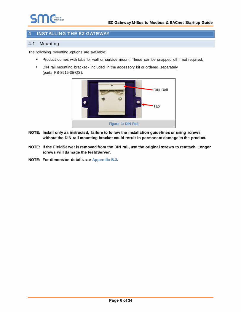
4.1 Mounting
The following mounting options are available:
Product comes with tabs for wall or surface mount. These can be snapped off if not required.
DIN rail mounting bracket - included in the accessory kit or ordered separately (part# FS-8915-35-QS).
NOTE: Install only as instructed, failure to follow the installation guidelines or using screws without the DIN rail mounting bracket could result in permanent damage to the product.
NOTE: If the FieldServer is removed from the DIN rail, use the original screws to reattach. Longer screws will damage the FieldServer.
NOTE: For dimension details see Appendix B.3.
Tab
DIN Rail
Figure 1: DIN Rail
EZ Gateway M-Bus to Modbus & BACnet Start-up Guide
Page 7 of 34
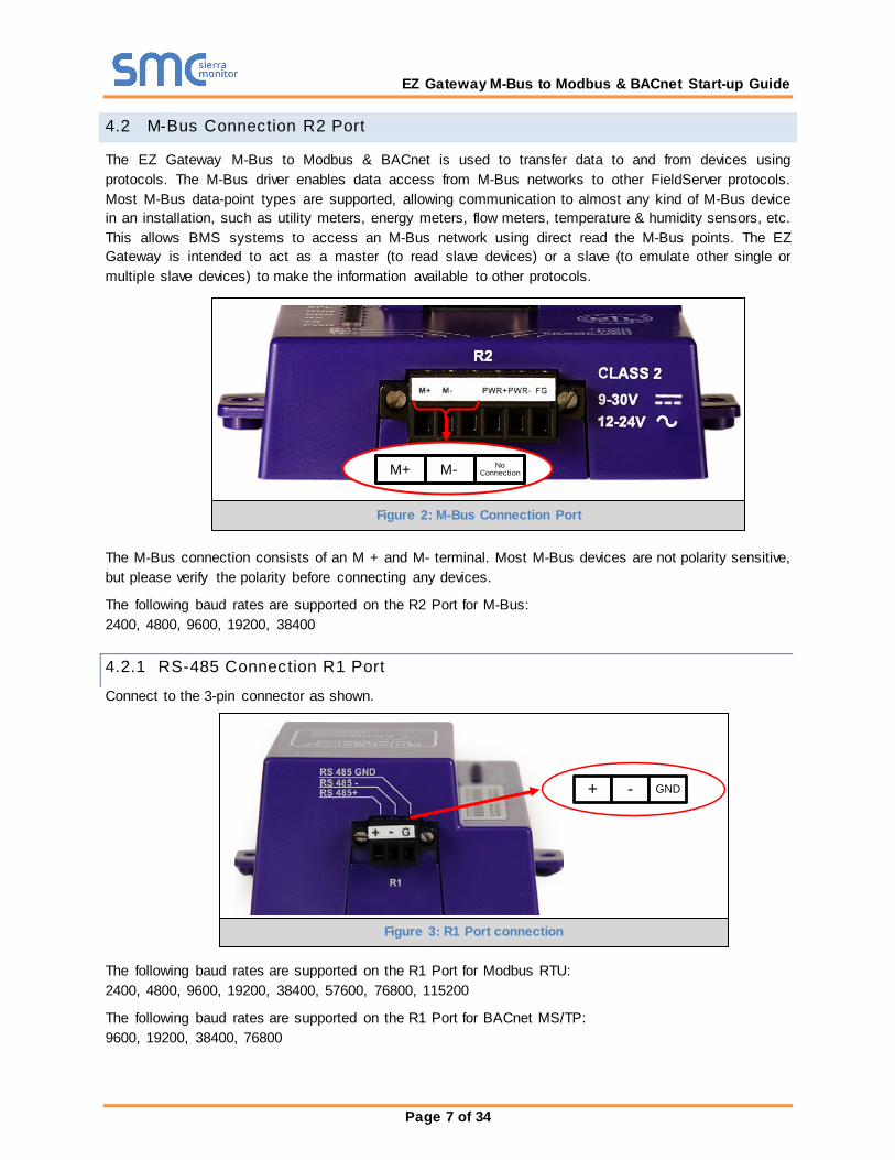
4.2 M-Bus Connection R2 Port
The EZ Gateway M-Bus to Modbus & BACnet is used to transfer data to and from devices using protocols. The M-Bus driver enables data access from M-Bus networks to other FieldServer protocols. Most M-Bus data-point types are supported, allowing communication to almost any kind of M-Bus device in an installation, such as utility meters, energy meters, flow meters, temperature & humidity sensors, etc. This allows BMS systems to access an M-Bus network using direct read the M-Bus points. The EZ Gateway is intended to act as a master (to read slave devices) or a slave (to emulate other single or multiple slave devices) to make the information available to other protocols.
The M-Bus connection consists of an M + and M- terminal. Most M-Bus devices are not polarity sensitive, but please verify the polarity before connecting any devices.
The following baud rates are supported on the R2 Port for M-Bus: 2400, 4800, 9600, 19200, 38400
4.2.1 RS-485 Connection R1 Port
Connect to the 3-pin connector as shown.
The following baud rates are supported on the R1 Port for Modbus RTU: 2400, 4800, 9600, 19200, 38400, 57600, 76800, 115200
The following baud rates are supported on the R1 Port for BACnet MS/TP: 9600, 19200, 38400, 76800
Figure 3: R1 Port connection
M+ M- No Connection
Figure 2: M-Bus Connection Port
+ - GND

EZ Gateway M-Bus to Modbus & BACnet Start-up Guide
Page 8 of 34
5 OPERATION
5.1 Power up the Device
Apply power to the device. Ensure that the power supply used complies with the specifications provided in Appendix B.1. Ensure that the cable is grounded using the “Frame GND” terminal. The EZ Gateway requires a power supply that provides 9-30V DC or 24V AC.
5.2 Connect the PC to the EZ Gateway over the Ethernet Port
Connect an Ethernet cable between the PC and EZ Gateway or connect the EZ Gateway and the
PC to the switch using a straight CAT5 cable.
The default IP Address of the EZ Gateway is 192.168.2.101, Subnet Mask is 255.255.255.0.
Ethernet Port
Figure 4: Power Connection
Figure 5: Ethernet Port
PWR+ PWR- FG

EZ Gateway M-Bus to Modbus & BACnet Start-up Guide
Page 9 of 34
5.3 Connecting to the EZ Gateway
5.3.1 Using the Toolbox Application to Discover and Connect to the EZ Gateway
Install the Toolbox application from the USB drive or download it from the Sierra Monitor website (www.sierramonitor.com/customer-care/resource-center?filters=software-downloads).
Use the Toolbox application to find the EZ Gateway and launch the Web App.
NOTE: If the connect button is greyed out, the EZ Gateway’s IP Address must be set to be on the same network as the PC. (Section 5.3.2)
5.3.2 Using the Web App
Open a web browser and connect to the EZ Gateway’s default IP Address. The default IP Address of the BACnet Router is 192.168.2.101, Subnet Mask is 255.255.255.0.
If the PC and the EZ Gateway are on different IP networks, assign a static IP Address to the PC on the 192.168.2.X network.
5.3.3 Accessing FieldPoP
The FieldPoP™ tab (see Figure 6) allows users to connect to FieldPoP, Sierra Monitor’s device cloud solution for the IIOT. FieldPoP enables secure remote connection to field devices through a FieldServer and its local applications for configuration, management, maintenance. For more information about FieldPoP, refer to the FieldPoP™ Device Cloud Start-up Guide.
Figure 6: EZ Gateway Landing Page
EZ Gateway M-Bus to Modbus & BACnet Start-up Guide
Page 10 of 34
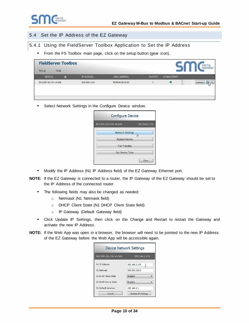
5.4 Set the IP Address of the EZ Gateway
5.4.1 Using the FieldServer Toolbox Application to Set the IP Address
From the FS Toolbox main page, click on the setup button (gear icon).
Select Network Settings in the Configure Device window.
Modify the IP Address (N1 IP Address field) of the EZ Gateway Ethernet port.
NOTE: If the EZ Gateway is connected to a router, the IP Gateway of the EZ Gateway should be set to the IP Address of the connected router.
The following fields may also be changed as needed: o Netmask (N1 Netmask field)
o DHCP Client State (N1 DHCP Client State field)
o IP Gateway (Default Gateway field)
Click Update IP Settings, then click on the Change and Restart to restart the Gateway and activate the new IP Address.
NOTE: If the Web App was open in a browser, the browser will need to be pointed to the new IP Address of the EZ Gateway before the Web App will be accessible again.
EZ Gateway M-Bus to Modbus & BACnet Start-up Guide
Page 11 of 34
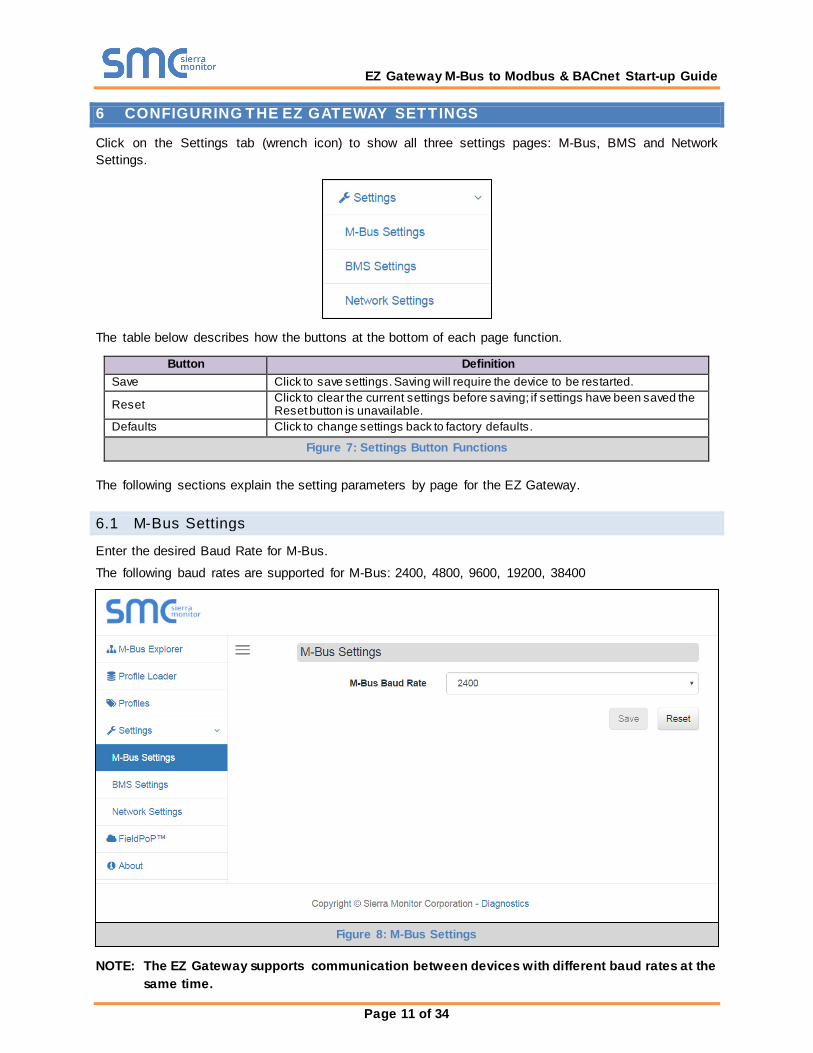
6 CONFIGURING THE EZ GATEWAY SETTINGS
Click on the Settings tab (wrench icon) to show all three settings pages: M-Bus, BMS and Network Settings.
The table below describes how the buttons at the bottom of each page function.
Button Definition Save Click to save settings. Saving will require the device to be restarted.
Reset Click to clear the current settings before saving; if settings have been saved the Reset button is unavailable.
Defaults Click to change settings back to factory defaults.
Figure 7: Settings Button Functions
The following sections explain the setting parameters by page for the EZ Gateway.
6.1 M-Bus Settings
Enter the desired Baud Rate for M-Bus.
The following baud rates are supported for M-Bus: 2400, 4800, 9600, 19200, 38400
NOTE: The EZ Gateway supports communication between devices with different baud rates at the same time.
Figure 8: M-Bus Settings
EZ Gateway M-Bus to Modbus & BACnet Start-up Guide
Page 12 of 34
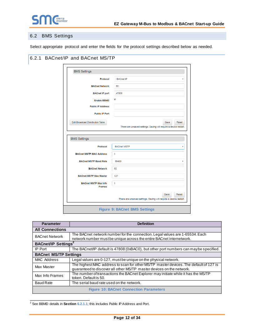
6.2 BMS Settings
Select appropriate protocol and enter the fields for the protocol settings described below as needed.
6.2.1 BACnet/IP and BACnet MS/TP
Parameter Definition
All Connections BACnet Network The BACnet network number for the connection. Legal values are 1-65534. Each
network number must be unique across the entire BACnet internetwork. BACnet/IP Settings2 IP Port The BACnet/IP default is 47808 (0xBAC0), but other port numbers can may be specified. BACnet MS/TP Settings MAC Address Legal values are 0-127, must be unique on the physical network.
Max Master The highest MAC address to scan for other MS/TP master devices. The default of 127 is guaranteed to discover all other MS/TP master devices on the network.
Max Info Frames The number of transactions the BACnet Explorer may initiate while it has the MS/TP token. Default is 50.
Baud Rate The serial baud rate used on the network.
Figure 10: BACnet Connection Parameters
2 See BBMD details in Section 6.2.1.1; this includes Public IP Address and Port.
Figure 9: BACnet BMS Settings
EZ Gateway M-Bus to Modbus & BACnet Start-up Guide
Page 13 of 34
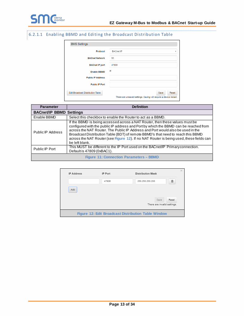
6.2.1.1 Enabl ing BBMD and Edi ting the Broadcast Distribution Table
Parameter Definition BACnet/IP BBMD Settings Enable BBMD Select this checkbox to enable the Router to act as a BBMD.
Public IP Address
If the BBMD is being accessed across a NAT Router, then these values must be configured with the public IP address and Port by which the BBMD can be reached from across the NAT Router. The Public IP Address and Port would also be used in the Broadcast Distribution Table (BDT) of remote BBMD's that need to reach this BBMD across the NAT Router (see Figure 12). If no NAT Router is being used, these fields can be left blank.
Public IP Port This MUST be different to the IP Port used on the BACnet/IP Primary connection. Default is 47809 (0xBAC1).
Figure 11: Connection Parameters – BBMD
Figure 12: Edit Broadcast Distribution Table Window
EZ Gateway M-Bus to Modbus & BACnet Start-up Guide
Page 14 of 34
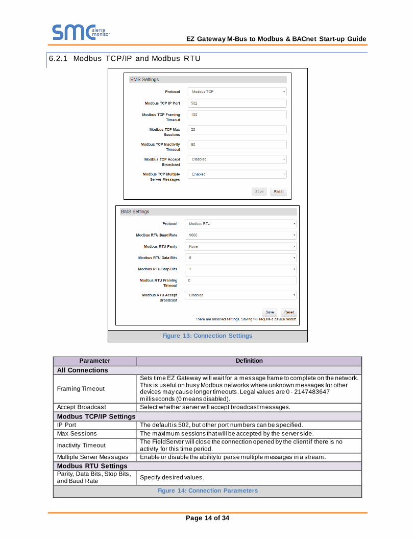
6.2.1 Modbus TCP/IP and Modbus RTU
Parameter Definition
All Connections
Framing Timeout
Sets time EZ Gateway will wait for a message frame to complete on the network. This is useful on busy Modbus networks where unknown messages for other devices may cause longer timeouts. Legal values are 0 - 2147483647 milliseconds (0 means disabled).
Accept Broadcast Select whether server will accept broadcast messages. Modbus TCP/IP Settings IP Port The default is 502, but other port numbers can be specified. Max Sessions The maximum sessions that will be accepted by the server side.
Inactivity Timeout The FieldServer will close the connection opened by the client if there is no activity for this time period.
Multiple Server Messages Enable or disable the ability to parse multiple messages in a stream. Modbus RTU Settings Parity, Data Bits, Stop Bits, and Baud Rate Specify desired values.
Figure 14: Connection Parameters
Figure 13: Connection Settings
EZ Gateway M-Bus to Modbus & BACnet Start-up Guide
Page 15 of 34
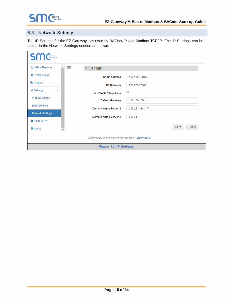
6.3 Network Settings
The IP Settings for the EZ Gateway are used by BACnet/IP and Modbus TCP/IP. The IP Settings can be edited in the Network Settings section as shown.
Figure 15: IP Settings
EZ Gateway M-Bus to Modbus & BACnet Start-up Guide
Page 16 of 34
7 USING THE EZ GATEWAY
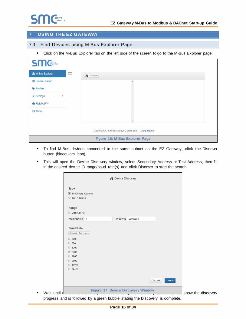
7.1 Find Devices using M-Bus Explorer Page
Click on the M-Bus Explorer tab on the left side of the screen to go to the M-Bus Explorer page.
To find M-Bus devices connected to the same subnet as the EZ Gateway, click the Discover button (binoculars icon).
This will open the Device Discovery window, select Secondary Address or Test Address, then fill in the desired device ID range/baud rate(s) and click Discover to start the search.
Wait until the Device Discovery process is complete - a blue progress bar will show the discovery progress and is followed by a green bubble stating the Discovery is complete.
Figure 16: M-Bus Explorer Page
Figure 17: Device Discovery Window

EZ Gateway M-Bus to Modbus & BACnet Start-up Guide
Page 17 of 34
Once the discovery is complete, new M-Bus devices connected to the same subnet should appear on the M-Bus Explorer page.
Figure 18: M-Bus Explorer Page with Discovered Devices

EZ Gateway M-Bus to Modbus & BACnet Start-up Guide
Page 18 of 34
7.2 Create a Profile from Existing Device Details
Click on the desired device to show Configuration Status, Details and Data.
Click on the Create New Profile button (under the Configuraiton Status section) to use a data map existing on the M-Bus device as the template for a new profile.
Figure 19: Device Information

EZ Gateway M-Bus to Modbus & BACnet Start-up Guide
Page 19 of 34
Define the Profile Settings as needed.
Edit the Data Map as needed.
o Click the Advanced button to see all possible mapping elements
Figure 20: New Profile – Select Profile Settings
Figure 21: New Profile – Edit Data Map
EZ Gateway M-Bus to Modbus & BACnet Start-up Guide
Page 20 of 34
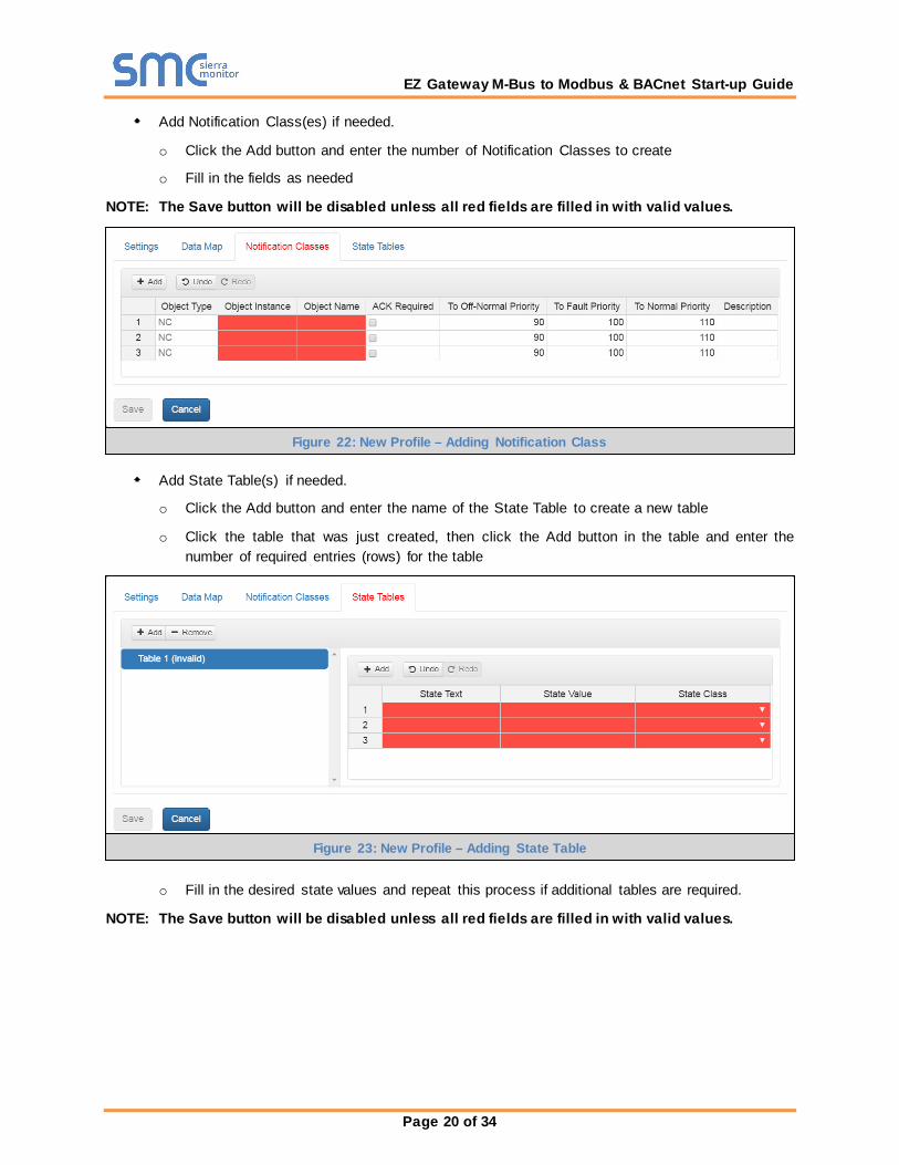
Add Notification Class(es) if needed.
o Click the Add button and enter the number of Notification Classes to create
o Fill in the fields as needed
NOTE: The Save button will be disabled unless all red fields are filled in with valid values.
Add State Table(s) if needed.
o Click the Add button and enter the name of the State Table to create a new table
o Click the table that was just created, then click the Add button in the table and enter the number of required entries (rows) for the table
o Fill in the desired state values and repeat this process if additional tables are required.
NOTE: The Save button will be disabled unless all red fields are filled in with valid values.
Figure 22: New Profile – Adding Notification Class
Figure 23: New Profile – Adding State Table
EZ Gateway M-Bus to Modbus & BACnet Start-up Guide
Page 21 of 34
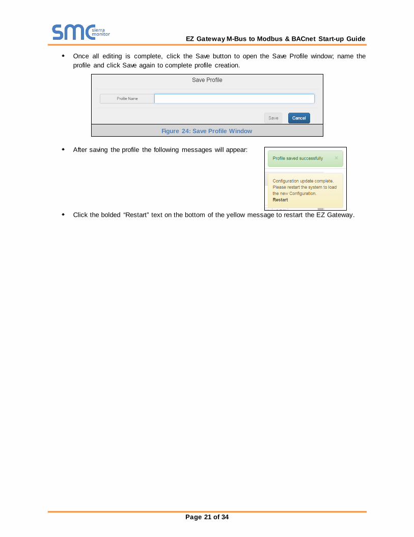
Once all editing is complete, click the Save button to open the Save Profile window; name the profile and click Save again to complete profile creation.
After saving the profile the following messages will appear:
Click the bolded “Restart” text on the bottom of the yellow message to restart the EZ Gateway.
Figure 24: Save Profile Window

EZ Gateway M-Bus to Modbus & BACnet Start-up Guide
Page 22 of 34
7.3 Manage Profiles using the Profiles Page
Click on the Profiles tab on the left side of the screen to go to the Profiles page.
NOTE: If a profile has been saved from a discovered device using the M-Bus Explorer, the saved profiles will appear on this page.
Profiles can be edited, deleted or exported as needed using the Action buttons to the right of each profile name.
Profiles can also be imported from the local PC using the Import button.
7.3.1 Import Button
To import profiles from the local PC, click the Import button .
Select the profile via the Import Profile window and click the Import button.
A green bubble will appear that states the profile has been imported sucessfully.
The new profile will now show on the Profiles page.
Figure 25: Device Profiles Page
Figure 26: Import Profile Window

EZ Gateway M-Bus to Modbus & BACnet Start-up Guide
Page 23 of 34
7.3.2 Edit Button
Through the Edit button the Profile Settings, Data Map, Notiication Classes and State Table can be redefined.
NOTE: See Section 7.2 for a walkthrough on editing profile information.
Once all editing is complete, click the Save button to open the Save Profile window; name the profile and click Save again to complete profile creation.
After saving the profile the following messages will appear:
Click the bolded “Restart” text on the bottom of the yellow message to restart the EZ Gateway.
Figure 28: Save Profile Window
Figure 27: Edit Profile Window
EZ Gateway M-Bus to Modbus & BACnet Start-up Guide
Page 24 of 34
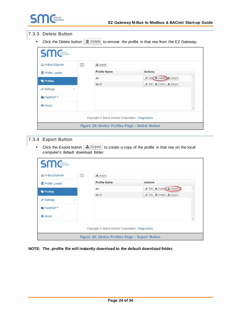
7.3.3 Delete Button
Click the Delete button to remove the profile in that row from the EZ Gateway.
7.3.4 Export Button
Click the Export button to create a copy of the profile in that row on the local computer’s default download folder.
NOTE: The .profile file will instantly download to the default download folder.
Figure 30: Device Profiles Page – Export Button
Figure 29: Device Profiles Page – Delete Button

EZ Gateway M-Bus to Modbus & BACnet Start-up Guide
Page 25 of 34
7.4 Set up Profiles using Profile Loader Page
Click on the Profile Loader tab on the left side of the screen to go to the Profile Loader page.
Click the Add button to open up the Profile Loader window.
Enter a Device Name and select a profile saved on the EZ Gateway.
o Once a profile has been selected in the Profile field, the M-Bus Parameter and BACnet Parameter fields will appear
Figure 32: Profile Loader Window
Figure 31: Profile Loader Page

EZ Gateway M-Bus to Modbus & BACnet Start-up Guide
Page 26 of 34
Enter parameter informaiton as needed.
Click Save and then click Restart when prompted to load the new settings.
Once restarted, the Profile Loader page will show the created profile instance.
Click the profile listing to view or edit the entry as needed.
Figure 33: Profile Loader Page with Created Profile Instance
Figure 34: Viewing Created Profile Instance Details
EZ Gateway M-Bus to Modbus & BACnet Start-up Guide
Page 27 of 34
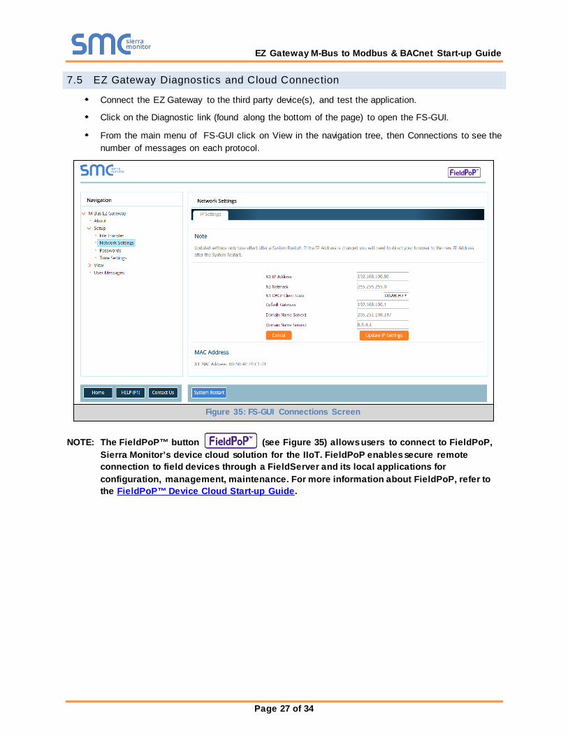
7.5 EZ Gateway Diagnostics and Cloud Connection
Connect the EZ Gateway to the third party device(s), and test the application.
Click on the Diagnostic link (found along the bottom of the page) to open the FS-GUI.
From the main menu of FS-GUI click on View in the navigation tree, then Connections to see the number of messages on each protocol.
NOTE: The FieldPoP™ button (see Figure 35) allows users to connect to FieldPoP, Sierra Monitor’s device cloud solution for the IIoT. FieldPoP enables secure remote connection to field devices through a FieldServer and its local applications for configuration, management, maintenance. For more information about FieldPoP, refer to the FieldPoP™ Device Cloud Start-up Guide.
Figure 35: FS-GUI Connections Screen
EZ Gateway M-Bus to Modbus & BACnet Start-up Guide
Page 28 of 34
Appendix A Troubleshooting
Appendix A.1. Communicating with the EZ Gateway over the Network
Confirm that the network cabling is correct.
Confirm that the computer network card is operational and correctly configured.
Confirm that there is an Ethernet adapter installed in the PC’s Device Manager List, and that it is configured to run the TCP/IP protocol.
Check that the IP netmask of the PC matches the EZ Gateway. The Default IP Address of the EZ Gateway is 192.168.2.X, Subnet Mask is 255.255.255.0.
o Go to Start|Run o Type in “ipconfig” o The account settings should be displayed o Ensure that the IP Address is 102.168.2.X and the netmask 255.255.255.0
Ensure that the PC and EZ Gateway are on the same IP Network, or assign a Static IP Address to the PC on the 192.168.2.X network.
Before Contacting Technical Support take a Diagnostic Capture Appendix A.1.
When a problem occurs that cannot be resolved with regular troubleshooting, take a log via the FieldServer Toolbox. Send this log together with a detailed description of the problem to [email protected] for evaluation. The diagnostic capture assists technical support to quickly solve the problem.
NOTE: While all necessary documentation is shipped with the FieldServer on the USB flash drive, these documents are constantly being updated. Newer versions may be available on the Sierra Monitor website Resource Center.
Ensure that FieldServer Toolbox is loaded onto the local PC. Otherwise, download the FieldServer-Toolbox.zip via the Sierra Monitor Resource Center Software Downloads.
Extract the executable file and complete the installation.
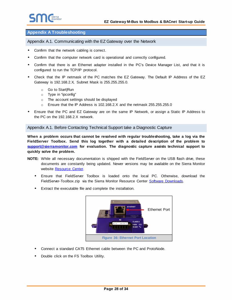
Connect a standard CAT5 Ethernet cable between the PC and ProtoNode.
Double click on the FS Toolbox Utility.
Ethernet Port
Figure 36: Ethernet Port Location
EZ Gateway M-Bus to Modbus & BACnet Start-up Guide
Page 29 of 34
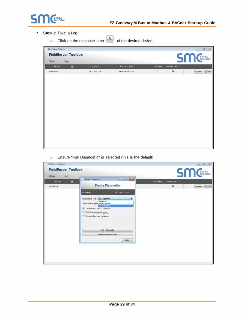
Step 1: Take a Log
o Click on the diagnose icon of the desired device
o Ensure “Full Diagnostic" is selected (this is the default)

EZ Gateway M-Bus to Modbus & BACnet Start-up Guide
Page 30 of 34
NOTE: If desired, the default capture period can be changed.
o Click on “Start Diagnostic”
o Wait for Capture period to finish, then the Diagnostic Test Complete window will appear
Step 2: Send Log o Once the Diagnostic test is complete, a .zip file will be saved on the PC
o Choose “Open” to launch explorer and have it point directly at the correct folder
o Send the Diagnostic zip file to [email protected]

EZ Gateway M-Bus to Modbus & BACnet Start-up Guide
Page 31 of 34
Appendix A.2. Notes Regarding Subnets and Subnet Masks
RFC standards allocate the IP Address range of 192.0.0.0 through to 223.255.255.255 to be used in Class-C subnetting (subnets listed as 255.255.255.xxx, where xxx can vary based on filtering required).
Consequently, the IP stack for this product will not allow any IP Addresses in this range to be allocated a subnet that does not fall within the Class C range.
Appendix A.3. LED Functions
Light Description
SPL SPL LED will be on when a configured node in the EZ Gateway is detected as being offline. For details, check the FS-GUI Node overview screen in FS-GUI (click “View” then “Nodes”).
RUN RUN LED will flash 20 seconds after power up, signifying normal operation. The EZ Gateway will be able to access the Web App (Section 5.3) once this LED starts flashing. During the first 20 seconds, the LED should be off.
ERR
The ERR LED will go on solid 15 seconds after power up. It will turn off after 5 seconds. A steady red light will indicate there is a system error on the FieldServer. If this occurs, immediately report the related “system error” shown in the FS-GUI User Messages error screen to technical support for evaluation.
RX On normal operation, the RX LED will flash when a message is received on the field port of the EZ Gateway.
TX On normal operation, the TX LED will flash when a message is sent on the field port of the EZ Gateway.
PWR This is the power light and should show steady green at all times when the EZ Gateway is powered.
Figure 37: LED Allocation

EZ Gateway M-Bus to Modbus & BACnet Start-up Guide
Page 32 of 34
Appendix B Reference
Appendix B.1. Specifications3
FS-EZX-MOD-BAC
Available Ports
One 6-pin Phoenix connector with: M-Bus port (+ / - / No Connection) Power port (+ / - / Frame-gnd)
One 3-pin Phoenix connector with: RS-485 port (+ / - / gnd) One Ethernet 10/100 BaseT port
Power Requirements
Input Voltage: 9-30V DC or 24V AC Input Power Frequency 50/60 Hz. Power Rating: 2.5 Watts Current draw @ 12V, 150 mA
Approvals
TUV approved to UL 916 Standard RoHS Compliant FCC Part 15 Compliant CE Mark BTL Mark
Surge Suppression EN61000-4-2 ESD EN61000-4-3 EMC EN61000-4-4 EFT Physical Dimensions (excluding the external power supply) (WxDxH) 5.05 x 2.91 x 1.6 in. (12.82 x 7.39 x 4.06 cm) excluding mounting tabs Weight 0.4 lbs (0.2 Kg) Environment Operating Temperature: -40°C to 75°C (-40°F to167°F) Humidity: 5 - 90% RH (non-condensing)
“This device complies with part 15 of the FCC Rules. Operation is subject to the following two conditions: This device may not cause harmful interference
This device must accept any interference received, including interference that may cause undesired operation.
NOTE: This equipment has been tested and found to comply with the limits for a Class A digital device, pursuant to part 15 of the FCC Rules. These limits are designed to provide reasonable protection against harmful interference when the equipment is operated in a commercial environment. This equipment generates, uses, and can radiate radio frequency energy and, if not installed and used in accordance with the instruction manual, may cause harmful interference to radio communications. Operation of this equipment in a residential area is likely to cause harmful interference in which case the user will be required to correct the interference at his expense. Modifications not expressly approved by Sierra Monitor could void the user's authority to operate the equipment under FCC rules”.
3 Specif ications subject to change w ithout notice.

EZ Gateway M-Bus to Modbus & BACnet Start-up Guide
Page 33 of 34
Appendix B.2. Compliance with UL Regulations
For UL compliance, the following instructions must be met when operating the EZ Gateway.
The units shall be powered by listed LPS or Class 2 power supply suited to the expected operating temperature range.
The interconnecting power connector and power cable shall: o Comply with local electrical code o Be suited to the expected operating temperature range o Meet the current and voltage rating for the EZ Gateway
Furthermore, the interconnecting power cable shall: o Be of length not exceeding 3.05m (118.3”) o Be constructed of materials rated VW-1, FT-1 or better
If the unit is to be installed in an operating environment with a temperature above 65 °C, it should be installed in a Restricted Access Area requiring a key or a special tool to gain access.
This device must not be connected to a LAN segment with outdoor wiring.
Appendix B.3. Dimension Drawing FS-EZX-MBUS-MOD-BAC
R1 Port
R2 Port
Figure 38: EZ Gateway Dimension Drawing

EZ Gateway M-Bus to Modbus & BACnet Start-up Guide
Page 34 of 34
Limited 2 Year Warranty
Sierra Monitor Corporation warrants its products to be free from defects in workmanship or material under normal use and service for two years after date of shipment. Sierra Monitor Corporation will repair or replace any equipment found to be defective during the warranty period. Final determination of the nature and responsibility for defective or damaged equipment will be made by Sierra Monitor Corporation personnel.
All warranties hereunder are contingent upon proper use in the application for which the product was intended and do not cover products which have been modified or repaired without Sierra Monitor Corporation’s approval or which have been subjected to accident, improper maintenance, installation or application, or on which original identification marks have been removed or altered. This Limited Warranty also will not apply to interconnecting cables or wires, consumables or to any damage resulting from battery leakage.
In all cases Sierra Monitor Corporation’s responsibility and liability under this warranty shall be limited to the cost of the equipment. The purchaser must obtain shipping instructions for the prepaid return of any item under this warranty provision and compliance with such instruction shall be a condition of this warranty.
Except for the express warranty stated above, Sierra Monitor Corporation disclaims all warranties with regard to the products sold hereunder including all implied warranties of merchantability and fitness and the express warranties stated herein are in lieu of all obligations or liabilities on the part of Sierra Monitor Corporation for damages including, but not limited to, consequential damages arising out of/or in connection with the use or performance of the product.