fertigation and irrigation management systems of vertical
TRANSCRIPT

International Journal of Soil Science and Agronomy ISSN:1725-3497 Vol. 5 (2), pp. 179-199, June, 2018. Available online at www.advancedscholarsjournals.org © Advanced Scholars Journals
Review paper
Fertigation and irrigation management systems of vertical gardens and green roofs
Dr. A.N.Sarkar
Ex-Senior Professor (International Business) & Dean (Research), Asia-Pacific Institute of Management, 3& 4 Institutional Areas, Jasola (Sarita Vihar), New Delhi
E.mail: [email protected]
Accepted 28 May, 2018.
Vertical gardens, Green roofs, walls and facades are becoming more common in cities across the globe. A Vertical Garden/ Green wall is comprised of plants grown in supported vertical systems that are generally attached to an internal or external wall, although in some cases can be freestanding. Like many green roofs, Vertical gardens incorporate vegetation, growing medium, irrigation and drainage into a single system. Vertical gardens differ from green facades in that they incorporate multiple ‘containerized’ plantings to create the vegetation cover rather than being reliant on fewer numbers of plants that climb and spread to provide cover. They are also known as ‘green walls’, ‘living walls’, ‘bio-walls’. Green roofs are constructed for multiple reasons - as spaces for people to use, as architectural features, to add value to property or to achieve particular environmental benefits (for example, storm-water capture and retention, improved species diversity, insulation of a building against heat gain or loss). Vegetation on green roofs is planted in a growing substrate (a specially designed soil substitution medium) that may range in depth from 50 mm to more than a metre, depending on the weight capacity of the building’s roof and the aims of the design. For growing different types of plants- either perennially or annually there is a need to supply constant, reliable and sustainable systems of irrigation and drainage; and preferably with a fertigation scheduling along with the sprinklers or overhead irrigation system. The paper discusses the various technological options that are open, system-worthy and cost-effective for providing fertigation and irrigation to plants/herbs grown in the vertical gardens as well as green roofs. Key words: Fertigation, Irrigation Management, Vertical Gardens, Green Roofs, insulation.
FERTIGATION: DEFINITION The practice of supplying crops in the field with fertilizers via the irrigation water is called fertigation (Bar-Yosef, 1991). Fertigation - a modern agro-technique provides an excellent opportunity to maximize yield and minimize environmental pollution (Hagin et al., 2002) by increasing fertilizer use efficiency, minimizing fertilizer application and increasing return on the fertilizer invested. In fertigation, timing, amounts and concentration of fertilizers applied are easily controlled. The incorporation of fertilizers into the irrigation system demands the following basic requirements (file:///C:/Users/Arnov%20Sarkar/Downloads/ifa_fertigation-Kafkafi-511.pdf): Equipment: In pressurized irrigation systems, the injected fertilizer solution has to be greater than that of the internal pressure.
A filter to prevent dripper clogging by any solid particles from reaching the dripper. A back-flow preventing valve. The choice of fertigation equipment has to take into account both crop requirement and irrigation system capacity. Fertilizers: Solubility of the fertilizers in the indigenous water source: irrigation water contains various chemical constituents some of which may interact with dissolved fertilizers with undesired effects. The degree of acidity of the fertilizer solution has to be considered in relation to its corrosiveness to the irrigation system components. Fertigation in Gravity Irrigation Systems This very simple method is only applicable to irrigation systems working at atmospheric pressure in

Dr. A.N.Sarkar 180 which water flows in open channels. The fertilizer solution drips into the irrigation channel because the fertilizer tank is above the level of the channel. In order to obtain good mixing, the velocity of the irrigation stream must be high enough. Fertigation in Pressurized Irrigation Systems Injection of the fertilizer consumes energy in order to overcome the internal pressure of the irrigation network. Fertilizer injection equipment is classified into three principals as given below (Fertigation- A Tool of efficient fertilizer and irrigation management: file:///C:/Users/Gollum/Downloads/ifa_fertigation-Kafkafi-511%20 (1).pdf): Fertigation: a tool for efficient fertilizer and water management groups, according to the means employed to obtain the higher pressure for the fertilizer solution. Injection by a Venturi Device: This is a unit that makes use of the Venturi suction principle by using the pressure induced by the flowing water to suck the fertilizer solution from the fertilizer tank into the irrigation line. A conical constriction in the pipe induces an increase in the water flow velocity and a pressure decrease to an extremely low value which causes fertilizer suction (through the filter screens) from the supply tank through a tube into the irrigation system. A valve can be adjusted to control the difference between the water velocities across the valves. Injection by differential pressure: This system utilizes an air tight pressure metal tank with anti-acid internal wall protection in which a pressure differential is created by a throttle valve that diverts part of the irrigation water into the tank. This is the only fertigation system that enables the use of both solid and liquid fertilizers. The entire fertilizer amount in the tank is delivered to the irrigation area. The concentration at the water emitter end is kept constant as long as a solid fertilizer is present in the tank and solubility of the fertilizer is quickly achieved. Once the solid fraction is completely dissolved the fertilizer concentration is reduced at an exponential rate. In practice, when four tank volumes have passed through it, only a negligible amount of fertilizer is left in the tank. This equipment was used in the early stages of fertigation development. A limited area can be irrigated at a time according to the tank volume. The use of solid fertilizers must be handled with care. Fertilizers that have endothermic reaction when dissolved, like KNO3, Ca (NO3)2, Urea, NH4NO3 and KCl decrease the temperature in the tank and when added during cold hours in the early morning before irrigation, part of the solution can freeze, leading to unexpected changes in the nutrient concentrations. Injection by Positive Pressure: Injection pumps are able to raise the pressure of the liquid fertilizer from a stock solution tank at a predetermined ratio between fertilizer solution volumes to irrigation water volume,
hence achieving a proportional distribution of nutrient in the irrigation water. The advantages of using injection pumps are the lack of pressure loss of the irrigation water, its accuracy and the ability to provide a determined concentration through the irrigation cycle. Two types of injectors are commonly used in fertigation: piston pumps and diaphragm pumps. The most common power sources for fertigation pumps are: Hydraulic Energy: The device uses the hydraulic pressure of the irrigation water to inject nutrient solution while the water used to propel it (approximately three times the volume of solution injected) is discharged. These pumps are suitable for fertigation in areas devoid of sources of electricity. Electric Dosing Pumps: The device activates the fertilizer pump. These are common in glasshouses and in areas where electricity is available and reliable. Fertilizer dosing in Fertigation According to Sne (2006), to apply the same doses of fertilizers during the specific phenological stage of a plant, two different patterns of application can be made depending on the crop, soil type and farm management system: Quantitative dosing: A measured amount of fertilizer is injected into the irrigation system during each water application. Injection may be initiated and controlled automatically or manually. Proportional dosing: In this process, a constant predetermined ratio between the volume of the irrigation water and the volume of the fertilizer solution is maintained, resulting in a constant nutrient concentration in the irrigation water. Suitability of Fertilizers for Fertigation A large range of fertilizers, both solid and liquid, are suitable for fertigation depending on the physicochemical properties of the fertilizer solution. For large scale field operations, solid fertilizer sources are typically a less expensive alternative to the commonly used liquid formulations. The solubility of these fertilizers does vary greatly. When switching to a solid fertilizer source, problems can be avoided in the nurse tanks by ensuring that ample water is added to the stock solution. Four main factors in selecting fertilizers for fertigation should be considered (Kafkafi, 1994, 2005, 2010): Plant type and Stage of Growth: Soil conditions, Water quality, Fertilizer Availability and Price The type of fertilizer for fertigation should be of high quality, with high solubility and purity, containing low salt levels and with an acceptable pH, and it must fit in the farm management program. Hagin and Lowengart-Aycicegi (1996) enumerated the main properties relating to the suitability of the fertilizer to the injection method as follows:

181 Int. J. Soil. Sci. Agron. Form: Soluble solid and liquid fertilizers are both suitable for fertigation depending on availability, profitability and convenience. Solubility: High and complete solubility is a prerequisite for fertilizers used in fertigation. Fertilizer solubility generally increases with temperature, depending on the fertilizer. Interaction between fertilizers in solution: When one type of fertilizer or more are prepared and mixed by the grower, or in the irrigation line (but to a lesser extent), the compatibility between them must be checked. There are usually some basic precautions that must be taken: Make sure that the fertilizers used are compatible to prevent precipitation. Especially, avoid mixing fertilizer solutions that contain calcium with solutions containing phosphates or sulfates when the pH in the solution is not sufficiently acidic. Check the solubility and potential precipitation with the local water chemical composition. Before using a new fertilizer, mix 50 ml of the fertilizer solution with 1 liter of the irrigation water and observe for precipitation within 1-2 hours. If precipitates are formed or the sample becomes cloudy, refrain from using this fertilizer in the irrigation system (Roddy, 2008). Check the temperature resulting from mixing various types of fertilizers under field conditions. Some fertilizers alone or in combination may lower the solution temperature to freezing levels (e.g. KNO3, Ca (NO3)2, urea, NH4NO3 and KCl. However, when purchasing ready-to-use liquid fertilizers, the endothermic reaction does not occur in the field, hence, slightly higher concentrations of nutrients in the solution can be achieved. Corrosivity. Chemical reactions may occur between fertilizers and metal parts in the irrigation and fertigation systems. Corrosion can harm metallic components of the system like uncoated steel pipes, valves, filters and injection units. FERTILIZER COMPOUNDS SUITABLE FOR FERTIGATION A large range of fertilizers, both solid and liquid, is offered to the grower. The suitability of a fertilizer for fertigation depends on several of its properties, especially its solubility in water. Solid fertilizers completely soluble at field temperature are suitable for fertigation; liquid fertilizers are already in solution. For mixing, fertilizers must be compatible. They must not form precipitates when mixed in water and their solubility must not be changed on mixing. For example, when mixing ammonium sulphate with potassium chloride, the decisive solubility will be that of potassium sulphate, having the lowest solubility in the mixture. Corrosivity of the solution is also important. Chemical reactions between fertilizers
and metal components in the irrigation system may occur. Acidic and/or chloride containing fertilizers are usually more corrosive than others. Fertilizer stock solutions that contain micronutrients in a chelated form should not be mixed with other fertilizer solutions. Separate stock solutions should be prepared for chelates and for acid solutions, because chelates tend to breakdown in acid solutions. Compatibility of fertilizers with the irrigation water has to be considered. Some water may contain relatively large concentrations of divalent cations, like calcium (Ca) and magnesium (Mg). Some phosphate compounds may easily precipitate in such water, while others, like polyphosphates may maintain their solubility. The solubility in water of fertilizers changes with temperature as shown in Table 1. These data are based on those in the Handbook of Chemistry and Physics, some data are taken from Wolf et al. (1985). The variation in solubility with temperature has to be taken into account, especially when preparing fertilizer stock solutions (Table 1). A fertilizer may be fully soluble at summer temperatures but precipitate out of the solution (salt out) in winter. Most water used for irrigation has an intrinsic salt content and thus an initial osmotic pressure, which is increased by adding more salts in the form of fertilizers. A relatively high osmotic pressure in the rooting liiedium is counter-productive to achieving large yields. At a raised osmotic pressure, the plant has to utilize more energy for water and nutrient uptake and this extra energy is expended at the cost of crop yield. Therefore, for fertigation solutions, the fertilizers that are used should generate the lower possible increase in osmotic pressure. The osmotic pressure of fertilizer of fertigation solutions is generally not stated nor measured. Instead, the electrical conductivity of the solution is measured and the osmotic pressure of various fertilizer solutions is compared according to the electrical conductivity. Nitrogen and potassium are sometimes side-dressed by application in the irrigation water that is applied to crop production systems at intervals during the growing season. This is termed fertigation. Phosphorus is not normally applied in this manner because it forms many insoluble compounds with other elements present in the irrigation water. This tends to clog up the irrigation system unless special care is taken to maintain the water pH at a level where most of these compounds will stay in solution. It is usually best to take care of phosphorus needs (if any exist; many soils contain more than adequate levels of phosphorus for crop production) by a broadcast application of concentrated super phosphate
fertilizer prior to crop establishment (http://utbeef.com/Content%20Folders/Forages/Fertilization/Publications/PB1637.pdf).
Foliar Feeding: Foliar-applied nutrients are absorbed and used by the plant quite rapidly. Absorption begins within minutes after application and is completed within one to two days with most nutrients. Foliar nutrition can

Dr. A.N.Sarkar 182
Table 1: Solubility of fertilizer compounds (g/L), at some temperatures
Source: Wolf et al. (1985).
supplement soil nutrition at a critical time for the plant (i.e., to maintain iron nutrition for an established acid-loving plant during the time period of soil pH adjustment with acid forming fertilizers), but it is not a substitute for soil application. This is especially true for the primary and secondary nutrients. In agronomic cropping systems, University of Tennessee research has shown benefit from foliar application of potassium in some cotton fields. Foliar feeding with potassium is indicated for cotton during the first two years of beginning soil potassium fertilization for those fields testing low in potassium (http://utbeef.com/Content%20Folders/Forages/Fertilization/Publications/PB1637.pdf). PRESSURIZED IRRIGATION SYSTEM The suitability of the various irrigation methods, i.e. surface, sprinkler or drip irrigation depends mainly on the following factors: natural conditions type of crop type of technology previous experience with irrigation required labour inputs costs and benefits. To choose an irrigation method, the farmer must know the advantages and disadvantages of the various methods. He or she must know which method suits the local conditions best. Unfortunately, in many cases there is no single best solution: all methods have their advantages and disadvantages. Testing of the various methods - under the prevailing local conditions - provides the best basis for a sound choice of irrigation method (http://www.fao.org/docrep/s8684e/s8684e08.htm).
MICRO-IRRIGATION SYSTEM The term micro-irrigation relates to irrigation technologies employing water emitters with tiny apertures that deliver water at low flow rates, less than 200 L/h. The primary use of non-drip micro-irrigation technology is in orchards (Figure 1). In the last decade, the use of micro-sprinklers has been extended to the irrigation of vegetables and field crops and in mobile center pivots and linear-move laterals. Micro emitters are commonly made from rigid plastic materials and are much smaller and cheaper than conventional sprinklers. Spoke-type static deflectors emit a number of streams that spray out from the emitter. These deflectors are less sensitive to windy conditions and the emitter is reliable because there are ' no moving parts. In the vibrating deflector type, the water is-ejected from a circular orifice and strikes a deflector that scatters the water around. This type of emitter is simple and reliable. In sprayers, mist-type deflectors form a fine spray, providing uniform coverage in sandy soils and are useful for frost protection. However, they are susceptible to wind and evaporation losses. The deflectors have a range of diverse configurations that allow coverage from 45° to 360°. Rotators are manufactured in different configurations. Their peculiarity is the rotation of the deflector around a central shaft and this allows them to irrigate a larger area than with orifice-type emitters. In spinners, the body with the nozzle is rotating. The inclusion of moving parts increases the sensitivity to external factors, as well as tear and wear. Most types of micro-sprinklers are

183 Int. J. Soil. Sci. Agron.
Figure 1: Micro irrigation in an orchard
versatile and flexible. Many components are interchangeable and facilitate low cost modification of flow-rate, range, distribution pattern and droplet size, according to specific requirements. Micro-sprinklers are less prone to clogging than drippers and when clogging occurs it is easy to notice and readily rectified. Some emitters are equipped with a small integral valve to allow the water to be shut-off for cleaning. Pressure compensated and flow regulated micro-sprinklers are used to irrigate steeply sloping land and pulse chambers allow the system to use a smaller volume of water. Micro-sprinklers are usually connected to the laterals by a plastic tube. They are commonly installed fastened to a stake to ensure they are in a vertical position. In some cases, threaded micro-sprinklers are installed on a 12 mni 35 to 18 mm rigid riser or directly on the lateral. In greenhouses, micro-sprinklers may be installed upside down for overhead irrigation. Micro-irrigation with foggers is used frequently in greenhouses for increasing the relative humidity and decreasing the temperature of the ambient air. They are operated intermittently in pulses by an automatic controller. Bridge type micro-sprinklers provide improved support to the rotating spinner, but the vertical part of the bridge creates a dry area behind the vertical support. SPRINKLER IRRIGATION SYSTEM This method consists of application of water to soil in the form of spray, somewhat as rain. It is particularly useful for sandy soils because they absorb water too fast. Soils that are too shallow, too steep or rolling can be irrigated efficiently with sprinklers. This method is suitable for areas having uneven topography and where erosion hazards are great. In sprinkler irrigation, water is conveyed under pressure through pipes to the area to be irrigated where it is passed out through or sprinklers the system comprises
four main parts Power Generator Pump Pipeline and Sprinkler. The power generator may be electrical or mechanical. A centrifugal pump may be used for suction lift up to 37 to 50 cm. A piston type pump is preferable where water is very deep. The pipe consists of two sections, the main line and the laterals. The main line may be permanently buried underground or may be laid above ground, if it is to be used on a number of fields. The main pipes are usually made of steel or iron. The laterals are lightweight aluminum pipes and are usually portable. The sprinkler nozzles may be single or double, revolving or stationery and mounted or riser pipes attached to riser. Each sprinkler head applies water to circular area whose diameter depends up on the size of water, which varies from ¼ to ¾ inch per hour is determined by selecting the proper combination of nozzles (http://www.agriinfo.in/default.aspx?page=topic&superid=7&topicid=21). The components of portable sprinkler system are shown through Figure 2. A sprinkler system usually consists of the following components (i) A pump unit (ii) Tubings- main/sub-mains and laterals (iii) Couplers (iv) Sprinker head (v) Other accessories such as valves, bends, plugs and risers Sprinkler irrigation (Figure 1) is compatible with diverse topographic conditions, such as uneven land and steep slopes that cannot be irrigated by surface irrigation. Diverse types of emitters and nozzles facilitate the tuning of the water application rate to the rate of infiltration into the soil. Uniform distribution of water in the field, accurate measurement of the applied water and high quality control accessories facilitate high water use efficiency. Sprinkler irrigation is sensitive to wind conditions. Wind reduces the uniformity of water distribution across the soil surface and decreases water use efficiency. Overhead irrigation may enhance leaf and fruit cryptogamic diseases and with water containing a high salt concentration may cause leaf-bum. The utilization of solid-sets and self-propelled systems minimizes the requirement for labour. When investment

Dr. A.N.Sarkar 184
Figure 2: Component of a portable sprinkler irrigation system
capital is short and labour is cheap; hand-move systems enable the irrigation of vast areas with relatively low initial capital investment. The operating routine is simple and reliable and operators require only a short period of training. All versions of sprinkler irrigation systems are adaptable to fertigation. Care has to be taken to avoid corrosion of metallic components by contact with corrosive fertilizers and scorching of the plant canopy by caustic fertilizers when using overhead sprinkler irrigation. Sprinklers are made of metal and plastic materials. Reinforced plastic moving parts and nozzles wear much less than metallic ones. The sprinklers are mounted on risers of various heights, according to the technique and the crop characteristics. With a dense plant population, like field crops and vegetables, even water distribution over the whole surface area is required. This is achieved by appropriate spacing between the laterals and between the sprinklers along the laterals, ensuring adequate overlapping. On the other hand, in orchards, even coverage of the soil surface is not feasible because of the interference of the tree canopy and in fact it is not required. Under-canopy sprinklers, without full overlapping between them, are used. In this case, each tree has to get the same water amount and the water distribution in the soil has to correspond with the spatial distribution of the root system. Adequate pressure in the range of 1 to 10 bars, at the sprinkler inlet, is a prerequisite for its operation. Sprinklers are driven by water pressure and each type has a limited range of allowed working pressure. A jet of water from a nozzle activates the moving parts of the sprinkler. Impact Sprinklers: The water jet, emitted from the nozzle, hits the hammer arm, driving it in a counter-clockwise direction until a spring returns the arm. The strike on the sprinkler body causes the body to rotate in the opposite direction. The impact sprinkler is fitted with one, two or three nozzles. Sprinklers come in various forms. In overhead irrigation of field crops and orchards
the ejection angle of the water jet is 15° - 30°. For under-canopy irrigation of orchards the recommended jet angle is 4 o - 7°. Impact sprinklers are very reliable, but require strict routine maintenance to guarantee long-term operation. Turbo-Hammer Sprinklers: The water jet moves a grooved wheel that hits the hammer which, in turn, rotates the sprinkler. The turbo-hammer sprinkler is made of plastic materials and is used for irrigation of orchards, vegetables and gardens at low discharge rates. Giant Sprinklers (guns): These are large-size hammer sprinklers made of brass with two or three nozzles. The working pressure is 4 to 8 bar and the discharge is 6 to 60 m3 /h. Giant sprinklers are used for irrigation of forage and field crops in solid set schemes or as single units as a travelling gun. Most hammer sprinklers have part-circle versions, which are capable of irrigating partial sectors of the wetting circle. Pop-Up Sprinklers: Pop-up sprinklers are commonly used for -the, irrigation of lawns and recreational grass. The sprinkler jumps upward at the start of the irrigation period and falls back into its underground, covered housing after shutdown. It remains there in a stand-by position until the next irrigation. There is a wide-range of pop-up sprinkler types, including part circle sprinklers, as well as rise-ups of various heights. (v) Static Sprinklers: They are made of brass or rigid plastic materials, without moving parts. These sprinklers are used mainly in gardens and irrigate a full or partial circle. The wetting range is smaller than that of rotating sprinklers. SPRINKLER IRRIGATION TECHNIQUES Hand-move: Sprinkler laterals of 50 and 75 mm diameter and 6 or 12 m long segments are moved from one position to another. Each lateral is transferred to several positions during the irrigation cycle. At the beginning of the next irrigation cycle, the laterals are moved forward along the distribution line and the terminal lateral is

185 Int. J. Soil. Sci. Agron. returned to the beginning of the field. This method is known as the "clock method" and is widely used. The hand-move method is usually applied with small areas of field crops, vegetables and orchards, and also in fields that are not suitable for the towline method. The method is labour intensive and requires physical effort. Towlines: The laterals are towed by tractor from one position to the next one. The number of tow positions will be twice the number of distribution lines corinllonly, laterals are towed between six positions but there are also fields with four, eight or even more positions. Hand-move in Orchards: Soft polyethylene laterals (grade 6) of 16, 20 or 25 mm diameter and up to 50 m long, with one or two sprinklers at the end of the lateral are pulled along the tree rows. At the beginning of the irrigation cycle the lateral is fully stretched. At the end of the first shift the lateral is pulled to its next position and so on until the cycle is completed. The equipment is returned to the starting position, by a "large move" to await the start of the next irrigation cycle. Solid-Set in Orchards Under Canopy Irrigation: Soft polyethylene (grade 4) pipes of 16, 20 or 25 mm diameters are laid out along the rows of the trees beside the trunks. Low-volume sprinklers, micro-sprinklers or micro-jets (up to 250 L/h) are mounted on the pipes or connected by means of a small diameter plastic tube. The application rate is low, ranging from 3 to 5 mm/h. The distance between emitters along the lateral corresponds to the tree spacing, one emitter per one or two trees. The sub-mains are commonly made of grade 4 or 6 bar, rigid polyethylene and are buried underground across the tree rows. Despite the high initial cost of this method, the solidset system replaces hand-move irrigation in orchards. Mini-sprinklers, micro-sprinklers, micro-jets and sprayers as well as drippers are the prevailing emitters that are used in orchards. Solid-set systems save labour, are conveniently operated and are compatible with all types of automatic control systems. The low jet angle prevents wetting of the canopy, decreasing leaf-diseases and washing pesticides off the leaves. Wind effects on the uniformity of water distribution are negligible. The system can be used to reduce damage during periods of frost or excessive heat. Fertigation is common in solid set systems in orchards. The short irrigation cycle and the improved control on wetting depth increase the efficiency of nutrient application and use. Overhead (Above Canopy) Irrigation: Rigid polyethylene pipes, 40-75 mm in diameter, grade 4, are stretched along the rows beside the trees. The sprinklers are mounted on high risers above the tops of the trees and are spaced 1 0 to 15 m. along the lateral, depending on tree spacing and orchard dimensions. Installation and operation are simple, labour investment is minimal and complete coverage will be attained if the sprinkler
positions and working pressure are adequate. There are a number of disadvantages of this system. A high working pressure and a low salt content in the irrigation water are essential and irrigation can be applied only at night and water is lost at the orchard margins, particularly important in small orchards. The wetting of the foliage enhances leaf and fruit diseases. In recent years, the under-canopy solid-set technology has replaced the above-canopy systems in orchards, except where overhead irrigation is significantly more efficient in decreasing frost damage. Low-volume solid-set systems in vegetables and field crops: In the last decade, there has been a considerable expansion in the use of low-volume mini-sprinklers in solid-set irrigation systems in vegetables and field crops grown in the open field. The emitters are modified orchard under canopy mini-sprinklers with an extended wetting diameter that enables spacing of 8x8 and lOxlO m. The initial investment is lower than in solid-set dripper systems or laterals with the common general-use sprinklers. The working pressure is relatively low and the economics of the system are satisfactory. The laterals are of 40-50 mm diameter to which mini-sprinklers are connected by means of small-diameter flexible tubes and are supported by 100-150 cm long metal rods inserted into the soil. Sprinkler: discharge .is 400-600 L/h and application rate is 4-6 mm/h. An advantage of this technology is the reduction in encrustation of the soil surface and prevention of runoff, due to the low intensity of irrigation. The main limitation of the technique is the sensitivity to wind. OPERATION AND MAINTENANCE OF SPRINKLER SYSTEMS Proper design of a sprinkler system does not in itself ensure success. It should be ensured that the prime mover and the pump are in alignment, particularly in the case of tractor-driven pumps. For these the drive shaft as well as the pump shaft should lie at nearly the same height to prevent too great an angle on the universal shaft. While laying the main and lateral pipes, always begin laying at the pump. This necessarily gives the correct connection of all quick coupling pipes. While joining couplings, it is ensured that both the couplings and the rubber seal rings are clean. In starting the sprinkler system, the motor or engine is started with the valves closed. The pump must attain the pressure stated on type-plate or otherwise there is a fault in the suction line. After the pump reaches the regulation pressure, the delivery valve is opened slowly. Similarly, the delivery valve is closed after stopping the power unit. The pipes and sprinkler-lines are shifted as required after stopping. Dismantling of the installation

Dr. A.N.Sarkar 186
takes place in the reverse order to the assembly described above. Maintenance General principles regarding the maintenance of the pipes and fittings and sprinkler heads are given below: Pipes and fittings The pipes and fittings require virtually no maintenance but attention must be given to the following procedures: (a) occasionally clean any dirt or sand out of the groove in the coupler in which the rubber sealing ring fits. Any accumulation of dirt or sand will affect the performance of the rubber sealing ring. (b) Keep all nuts and bolts tight. (c) Do not lay pipes on new damp concrete or on piles of fertilizer. Do not lay fertilizer sacks on the pipe. Sprinkler heads The sprinkler heads should be given the following attention: (a) When moving the sprinkler lines, make sure that the sprinklers are not damaged or pushed into the soil. (b) Do not apply oil, grease or any lubricant to the sprinklers. They are water lubricated and using oil, grease or any other lubricant may stop them from working. (c) Sprinklers usually have a sealed bearing and at the bottom of the bearing there are washers. Usually it is the washers that wear and not the more expensive metal parts. Check the washers for wear once a season or every six months which is especially important where water is sandy. Replace the washers if worn. (d) After several season's operation the swing arm spring may need tightening. This is done by pulling out the spring end at the top and rebending it. This will increase the spring tension. In general, check all equipment at the end of the season and make any repairs and adjustments and order the spare parts immediately so that the equipment is in perfect condition to start in the next season. Storage The following points are to be observed while storing the sprinkler equipment during the off season: Remove the sprinklers and store in a cool, dry place. Remove the rubber sealing rings from the couplers and fittings and store them in a cool, dark place. The pipes can be stored outdoors in which case they should be placed in racks with one end higher than the other. Do not store pipes along with fertilizer. Disconnect the suction and delivery pipe-work from the pump and pour in a small quantity of medium grade oil. Rotate the pump for a few minutes. Blank the suction and delivery branches. This will prevent the pump from rusting. Grease the shaft. Protect the
electric motor from the ingress of dust, dampness and rodents. Drip Irrigation System Drip irrigation is used for the most precise water application related to crop water requirement and root system development. Drip irrigation employs a lower pressure than sprinkler irrigation and can be conveniently integrated with different levels of automatic control. Thus, it is very well suited to fertigation. Drip irrigation is independent of wind conditions and can be applied at any time of the day. Weed development is restricted because there is only partial wetting of the soil surface. A voiding the wetting of crop leaves decreases infection and spread of leaf diseases and leaf scorch. A pattern of soil wetting under drip irrigation is illustrated in Plate Dripper Types A low flow rate is the working principle of a dripper system. The low flow rate through an ordinary orifice would require an extremely small opening increasing the risk of clogging. This risk is reduced by using a wider water passage and dissipating the water pressure by friction within the walls of the dripper by a long spiral water path, or a labyrinth path, or by a vortex. Several types of drippers are shown in Figure 3. The dependence of the dripper's flow rate on pressure can be expressed by the following Equation: q = kP", where: q = dripper's flow rate in L/h. k = dripper's constant, relates to the units of the flow rate and the pressure. P =the pressure head at the dripper's inlet. e = exponent, depends on the flow regime in the dripper. In non-regulated drippers the range of e is 0.4-1.0; in laminar flow in very thin tubes, the value of e is 1.0; in long spiral path drippers it is 0.7 and in vortex drippers it is 0.5. Because the flow rate is less dependent on the pressure head it is possible to have a small difference in the drippers flow rate, between the initial and the distal end of the dripper's lateral. 36 Historically, long path drippers were the first to be used. The labyrinth and the vortex types were developed later and allowed the production of smaller and cheaper drippers. The turbulent water flow in these two types dissipates the water pressure along a relatively short path. The pressure loss in the labyrinth type is created by changing the direction and diameter of the flow path along its length to generate turbulent flow. In the vortex drippers, the water enters the dripper in a tangential direction causing turbulence and a large loss in pressure. The working pressure of drippers ranges between 0.5 and 4.0 bars; and the flow rate between 1.0 and 8.0 Llh. In some types of tape dripper laterals, lower flow rates of 0.1 to 0.5 Llh from each emitter outlet are feasible. The

187 Int. J. Soil. Sci. Agron.
Figure 3: Types of drippers (Netafim, Metzer, T-tape).
low flow-rate of emitters in drip irrigation requires close spacing of the drippers on the lateral, ranging between 0.2 and 2 m. The distance between laterals depends on the spacing between the rows. In orchards, one or two laterals per tree row is common. In more densely grown annuals, like cotton and tomatoes, one lateral irrigates one or two crop rows. With thin-wall tapes the water outlets can be at 0.1 m along the lateral at no extra cost. Most of the drip-irrigated area is "on-surface" but in the last two decades, sub-surface drip irrigation has expanded. The risk of clogging by root intrusion is prevented by routine injection of chemicals that sterilize the soil in close proximity to the dripper and prevent root penetration. The clogging of drippers by soil particles, caused by suction after water shut-off, is prevented by the installation of vacuum break valves that enable air flow into the system immediately after shut-off." The wall thickness of dripper laterals made of soft polyethylene and P.V.C. depends on the working pressure. The grade is defined according to the allowed working pressure in the range of0.5-4.0 bar (5-40 m). Because of the relative low working pressure, drip systems require the use of pressure regulators in the control head. FERTILIZER INJECTION TECHNOLOGY Fertigation in Surface Irrigation System Fertigation is not a common practice in surface irrigation. When fertigation is applied, solid fertilizer or fertilizer solution can be poured into the water canal in a pre-determined amount. The instrumentation used is chosen from a wide range of devices beginning with a tank having an adjustable aperture in the bottom for solid fertilizers or a manually adjusted valve for fertilizer 39 solutions, and ending with the most sophisticated injection equipment integrated with automatic valves in surge irrigation. Anhydrous ammonia is injected into the
irrigation system by its intrinsic pressure. The application of fertilizers in surface irrigation may be wasteful. A significant amount of the fertilizer, notably N, may be lost in tail water and in deep percolation. Nevertheless, there are growers that apply fertilizers with surface irrigation, insisting that the larger yields and better quality compensate for the financial cost of the fertilizer lost. Fertigation is used frequently in zero slope and surge irrigation, where its efficiency has been proved. Fertigation Technology in Pressurized Irrigation System In pressurized irrigation there is, by definition, pressure within the network. Injecting fertilizer solution into the system requires generating a pressure differential to overcome the internal pressure. Fertilizer Tank (Figure 4): A pressure differential is generated by decreasing the water flow in the control head and diverting a fraction of the water through a tank containing the fertilizer solution. A gradient of 0.1-0.2 bar is needed to divert an adequate amount of water through a tube of 9-12 mm diameter. The tank, made of corrosion resistant enamel-coated or galvanized cast iron, stainless steel or fiberglass, has to withstand the network working pressure. Solid soluble fertilizers dissolving gradually in the tank or liquid fertilizers mix with the flowing water. The nutrient concentration is more or less constant, as long as some solid fertilizer remains in the tank. At later stages, once the solid has gone, the concentration decreases, due to continued dilution of the fertilizer solution. The system is relatively simple and cheap. There is no need for an external energy source and a vast dilution ratio can be achieved. There are some drawbacks, however, the fertilizer injection rate and nutrient concentration in the irrigation water cannot be precisely regulated and before
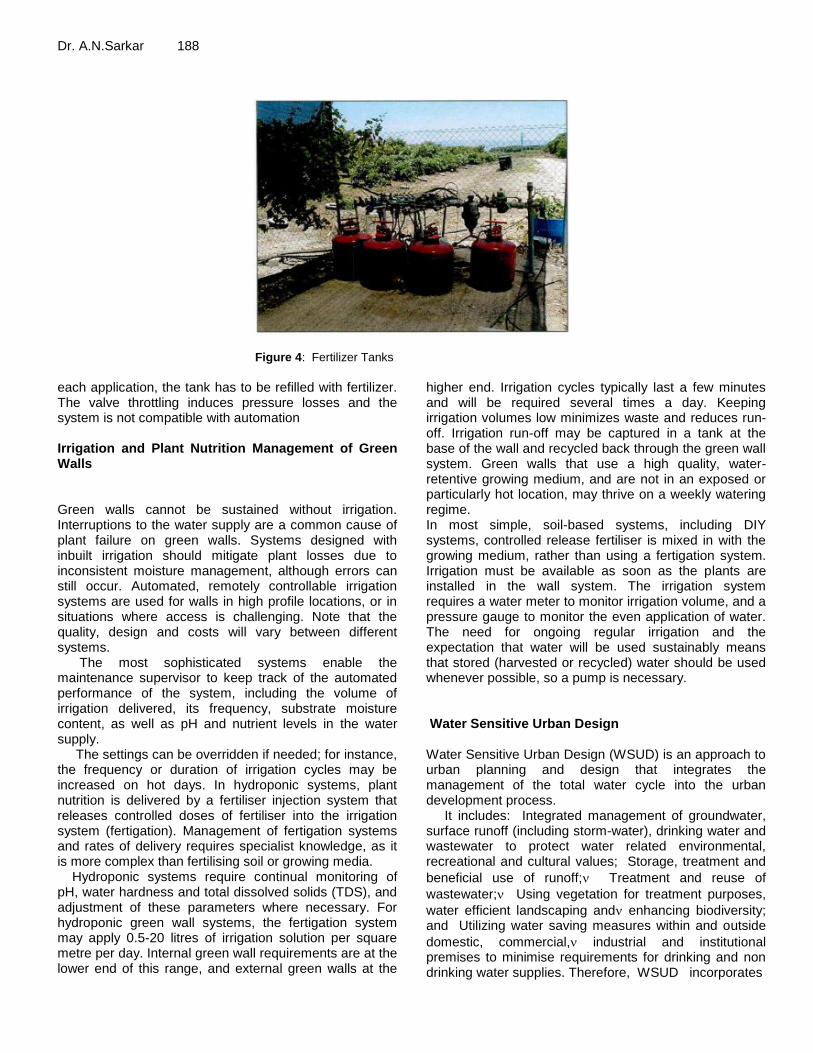
Dr. A.N.Sarkar 188
Figure 4: Fertilizer Tanks
each application, the tank has to be refilled with fertilizer. The valve throttling induces pressure losses and the system is not compatible with automation Irrigation and Plant Nutrition Management of Green Walls Green walls cannot be sustained without irrigation. Interruptions to the water supply are a common cause of plant failure on green walls. Systems designed with inbuilt irrigation should mitigate plant losses due to inconsistent moisture management, although errors can still occur. Automated, remotely controllable irrigation systems are used for walls in high profile locations, or in situations where access is challenging. Note that the quality, design and costs will vary between different systems. The most sophisticated systems enable the maintenance supervisor to keep track of the automated performance of the system, including the volume of irrigation delivered, its frequency, substrate moisture content, as well as pH and nutrient levels in the water supply. The settings can be overridden if needed; for instance, the frequency or duration of irrigation cycles may be increased on hot days. In hydroponic systems, plant nutrition is delivered by a fertiliser injection system that releases controlled doses of fertiliser into the irrigation system (fertigation). Management of fertigation systems and rates of delivery requires specialist knowledge, as it is more complex than fertilising soil or growing media. Hydroponic systems require continual monitoring of pH, water hardness and total dissolved solids (TDS), and adjustment of these parameters where necessary. For hydroponic green wall systems, the fertigation system may apply 0.5-20 litres of irrigation solution per square metre per day. Internal green wall requirements are at the lower end of this range, and external green walls at the
higher end. Irrigation cycles typically last a few minutes and will be required several times a day. Keeping irrigation volumes low minimizes waste and reduces run-off. Irrigation run-off may be captured in a tank at the base of the wall and recycled back through the green wall system. Green walls that use a high quality, water-retentive growing medium, and are not in an exposed or particularly hot location, may thrive on a weekly watering regime. In most simple, soil-based systems, including DIY systems, controlled release fertiliser is mixed in with the growing medium, rather than using a fertigation system. Irrigation must be available as soon as the plants are installed in the wall system. The irrigation system requires a water meter to monitor irrigation volume, and a pressure gauge to monitor the even application of water. The need for ongoing regular irrigation and the expectation that water will be used sustainably means that stored (harvested or recycled) water should be used whenever possible, so a pump is necessary. Water Sensitive Urban Design Water Sensitive Urban Design (WSUD) is an approach to urban planning and design that integrates the management of the total water cycle into the urban development process. It includes: Integrated management of groundwater, surface runoff (including storm-water), drinking water and wastewater to protect water related environmental, recreational and cultural values; Storage, treatment and
beneficial use of runoff; Treatment and reuse of
wastewater; Using vegetation for treatment purposes,
water efficient landscaping and enhancing biodiversity; and Utilizing water saving measures within and outside
domestic, commercial, industrial and institutional premises to minimise requirements for drinking and non drinking water supplies. Therefore, WSUD incorporates
189 Int. J. Soil. Sci. Agron.
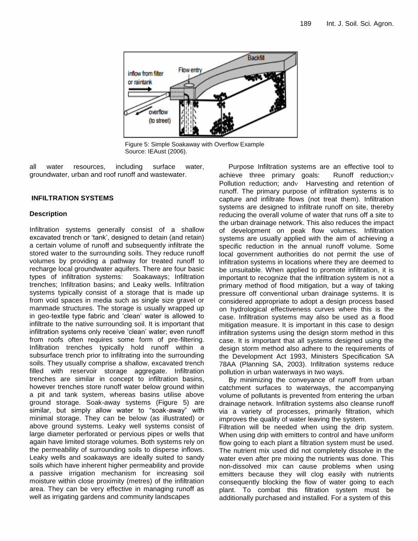
Figure 5: Simple Soakaway with Overflow Example Source: IEAust (2006).
all water resources, including surface water, groundwater, urban and roof runoff and wastewater. INFILTRATION SYSTEMS Description Infiltration systems generally consist of a shallow excavated trench or ‗tank‘, designed to detain (and retain) a certain volume of runoff and subsequently infiltrate the stored water to the surrounding soils. They reduce runoff volumes by providing a pathway for treated runoff to recharge local groundwater aquifers. There are four basic types of infiltration systems: Soakaways; Infiltration trenches; Infiltration basins; and Leaky wells. Infiltration systems typically consist of a storage that is made up from void spaces in media such as single size gravel or manmade structures. The storage is usually wrapped up in geo-textile type fabric and ‗clean‘ water is allowed to infiltrate to the native surrounding soil. It is important that infiltration systems only receive ‗clean‘ water; even runoff from roofs often requires some form of pre-filtering. Infiltration trenches typically hold runoff within a subsurface trench prior to infiltrating into the surrounding soils. They usually comprise a shallow, excavated trench filled with reservoir storage aggregate. Infiltration trenches are similar in concept to infiltration basins, however trenches store runoff water below ground within a pit and tank system, whereas basins utilise above ground storage. Soak-away systems (Figure 5) are similar, but simply allow water to ―soak-away‖ with minimal storage. They can be below (as illustrated) or above ground systems. Leaky well systems consist of large diameter perforated or pervious pipes or wells that again have limited storage volumes. Both systems rely on the permeability of surrounding soils to disperse inflows. Leaky wells and soakaways are ideally suited to sandy soils which have inherent higher permeability and provide a passive irrigation mechanism for increasing soil moisture within close proximity (metres) of the infiltration area. They can be very effective in managing runoff as well as irrigating gardens and community landscapes
Purpose Infiltration systems are an effective tool to
achieve three primary goals: Runoff reduction;
Pollution reduction; and Harvesting and retention of runoff. The primary purpose of infiltration systems is to capture and infiltrate flows (not treat them). Infiltration systems are designed to infiltrate runoff on site, thereby reducing the overall volume of water that runs off a site to the urban drainage network. This also reduces the impact of development on peak flow volumes. Infiltration systems are usually applied with the aim of achieving a specific reduction in the annual runoff volume. Some local government authorities do not permit the use of infiltration systems in locations where they are deemed to be unsuitable. When applied to promote infiltration, it is important to recognize that the infiltration system is not a primary method of flood mitigation, but a way of taking pressure off conventional urban drainage systems. It is considered appropriate to adopt a design process based on hydrological effectiveness curves where this is the case. Infiltration systems may also be used as a flood mitigation measure. It is important in this case to design infiltration systems using the design storm method in this case. It is important that all systems designed using the design storm method also adhere to the requirements of the Development Act 1993, Ministers Specification SA 78AA (Planning SA, 2003). Infiltration systems reduce pollution in urban waterways in two ways. By minimizing the conveyance of runoff from urban catchment surfaces to waterways, the accompanying volume of pollutants is prevented from entering the urban drainage network. Infiltration systems also cleanse runoff via a variety of processes, primarily filtration, which improves the quality of water leaving the system. Filtration will be needed when using the drip system. When using drip with emitters to control and have uniform flow going to each plant a filtration system must be used. The nutrient mix used did not completely dissolve in the water even after pre mixing the nutrients was done. This non-dissolved mix can cause problems when using emitters because they will clog easily with nutrients consequently blocking the flow of water going to each plant. To combat this filtration system must be additionally purchased and installed. For a system of this
Dr. A.N.Sarkar 190 size a simple mesh irrigation filter can be purchased and installed for under $100. This does drive up the systems starting cost but can save you headaches from clogged filters in the long run (http://digitalcommons.calpoly.edu/cgi/viewcontent.cgi?article=1108&context=braesp). RAIN GARDENS, GREEN ROOFS AND INFILTRATION SYSTEMS Water Sensitive Urban Design – Greater Adelaide Region Technical Manual – December 2010 Water harvesting schemes can be undertaken with the application of infiltration systems. Collection of water after infiltration using subsurface storages, or a combination of pervious pipes and offline storages, can be undertaken. They therefore present an opportunity to address the pressing needs of the community to employ other sources of water for fit for purpose use. Infiltration systems effectively strip a proportion of the runoff from urban areas and infiltrate this to underlying soils and groundwater. They also provide limited water quality control, primarily through mechanical filtration processes. Other treatment processes can be enhanced using engineered soils or geo-fabrics. Application / Scale Infiltration systems are limited to soils with good infiltrative capacity. They should also be sited with adequate buffer distances from foundations, neighbouring properties and existing in ground infrastructure. Infiltration systems can be operated at a variety of scales, from receiving the overflow from a rainwater tank, to regional scale systems receiving treated runoff from large catchments. Infiltration trenches are best suited to small (< 2 hectare catchment) residential, commercial and industrial developments with high percentages of impervious areas, including parking lots, high density residential housing and roadways. Infiltration trenches are commonly used with overlying pervious pavements as an effective water treatment chain. Infiltration basins are best suited to medium to large (5 to 50 hectare catchment) residential, commercial and industrial developments with high percentages of impervious areas, including parking lots, high density residential housing and roadways (Upper Parramatta River Catchment Trust, 2004). DESIGN CONSIDERATIONS The following sections provide an overview of the key design issues that should be considered when conceptualizing and designing an infiltration system. A typical infiltration strategy is illustrated in A number of these design considerations are discussed briefly below. Depth: The Development Act 1993 Ministers Specification SA78AA (Planning SA 2003) has limited
excavation depth for an infiltration system to 1.5 metres due to the restrictions imposed on excavations greater than 1.5 metres by the South Australian Occupational Health, Safety and Welfare Regulations 1995. A permit is required to construct an infiltration system greater than 2.5 metres under the requirements of the Natural Resources Management Act 2004. Site Setback and Distances: In accordance with the Development Act 1993 Ministers Specification SA 78AA (Planning SA. 2003) the use of infiltration systems is restricted to soil types A and S or Class M-D where the characteristic surface movement is equal to or less than 25 millimetres, as defined in the document AS 2870. Residential Slabs and Footings, Construction, and where the following conditions exist: The slope of the natural ground does not exceed 1 in 10. The depth to rock is 1.2 metres or greater; and the groundwater table is permanently below 1.5 metres from the natural
ground surface or the final ground surface, whichever is the lowest. The design of infiltration systems must take into consideration their proximity to existing structures and boundaries. The Development Act 1993 Ministers Specification SA 78AA (Planning SA, 2003) specifies that: Retention devices shall be located a minimum of 3 metres from all
property boundaries, (excluding front boundaries and/or reserves) and 3 metres from footings of all structures located on the allotment; and A minimum clear spacing of
1 metre between the sides of the retention device and any service trench is required. Further recommendations are provided by Argue (Ed., 2009) on the appropriate setback of infiltration systems with respect to different soil types. Water consumption may be an important determinant due to the increasing shortage of this resource in some places. The amount of water required by these systems, used in plant transpiration and substrate evaporation processes, is tightly related to air temperature and humidity, incoming solar energy, speed of the air flow, vegetation type, and substrate characteristics (Franco-Salas et al., 2012). Therefore, good species selection is a key design parameter to minimize water requirements in drought-prone areas. Also, recirculating the irrigation water or mixing it with reclaimed greywater and rainwater may considerably reduce the amount of water required. However, implementing water storage tanks for rainfall capture and/or irrigation water recycling may substantially increase the cost of materials and the installation of VGSs. As denoted by Ghaffarian-Hoseini et al. (2015), one of the main factors inhibiting the use of these systems is the initial capital investment, so the installation and size of water storage tanks as an environmentally friendly and water saving strategy for VGSs must be thoroughly analyzed for each case study and geographical location. For instance, installation of rainwater harvesting systems for meeting residential non-potable water demands in

191 Int. J. Soil. Sci. Agron.
Figure 6: Rain Gardens, Green Roofs and Infiltration Systems 6 6-25 Water Sensitive Urban Design – Greater Adelaide Region Technical Manual – December 2010
humid regions is expected to be more effective than in urban areas with moderate rainfall, whereas in arid climates their performance seems to be inefficient (Rashidi Mehrabadi et al., 2013). Similarly, Ward et al. (2012) showed that, by optimizing the size of water storage tanks in a humid climate, the payback period of a large building rainwater-harvesting system could be reduced from 11 to 6 years. Like green roofs, VGSs are also considered to improve urban water quality through storm water retention and filtration (Stav, 2008). However, the scientific evidence of this environmental benefit is still insufficient, as the few existing studies shed contradictory results (Berndtsson, 2010). Green Wall Irrigation Systems GENERAL CONSIDERATIONS: A successful long term installation will bring about a reliable watering system. Inadequate irrigation will cause walls to fail. 2 types of irrigation system: basic timer controlled dripper lines and commuter controlled systems with automatic moisture monitoring, leakage detection, etc. Irrigation frequency and any additional nutrient supply required will depend on the location the plants are growing from. Plant species that are typically hardy and robust and able to support their growth with minimal intervention will be preferred as they require a relatively simple irrigation system. A more reliable and a fairly sophisticated automated irrigation system will suit a modular living wall better. WATER SUPPLY METHODS: Green Facades
Drip irrigation utilizing emission devices at the base of every plant or incorporated into a surrounding sprinkler system. Living Walls Drip irrigation utilizing emission devices at every panel or cell. Growing Media Types and Substrate Systems There are 2 types of substrate used for green facades and green wall: A soil-less (hydroponic) technique, which takes advantage of plants that do not require soil to grow. Soil- based system, which are typically used for moulded troughs or container built on or attached to existing walls. Soil-less Technique Systems are grown on pre-constructed panels prior to vertical installation, using a specialist growing medium as root support. Systems are assembling off site and once ready, panel will be transported to site and attached to a framework on the side o f the wall to be covered. Once installed plants will continue to grow and further cover the wall. Soil-Based System Plants are supported by soil-based substrated similar to those used in green roof installations. Substrate utilized a lightweight combination of recycled materials containing the right balance of nutrients with free draining medium. Substrate with natural water retention properties, allow irrigation system to be simple in design and construction, thus lowering installation of maintenance costs. Maintenance

Dr. A.N.Sarkar 192 Green walls are living systems which require some degree of maintenance. Level of maintenance includes need for plant pruning, feeding and replacement. Some systems require monitoring to ensure structural elements remain secure and do not deteriorate. Longevity of green wall can be maximized by highlighting cost and requirements early. Degree of maintenance may be influenced by client expectations of aesthetic qualities of a living wall installation and the level of flourishing vegetation needed to be maintained. Access Besides the obvious height challenges, there are a number of access issues when installing and subsequently maintaining green walls. Ease of access to structure depends on the type of system chosen. It is better to plan a green wall installation during original design of building rather than relying on retrofitting after. Green facades require access to base of wall, especially once plants have established it is growth and initial coverage achieved, although some periodic pruning are still required. Some system requires regular access to complete structure for maintenance and monitoring. Staging, platforms, etc are often required to provide safe and effective access for maintenance tasks. Insulation Green roofs may or may not include an insulating layer in addition to the soil and vegetation, but even without such a layer they provide significant thermal insulation and shading for the building. Overall insulation values depend on the type and thickness of growing medium, and the type and extent of vegetation. There is little available documentation for R-values; they would, in any case, vary according to the degree of saturation of the growing medium. Green roofs provide significant thermal insulation and shading for a building. In Australia, the energy benefits of green roofs are most pronounced in their ability to reduce summer cooling demands. Their contribution to insulating and shading buildings can help significantly in reducing energy consumption and carbon pollution. However, it is difficult to obtain accredited insulation values for green roof construction. For specifying and code compliance purposes, thermal insulation standards should be met by conventional means with the additional insulation value of a green roof regarded as a bonus (an energy assessor may be able to give some credit for a green roof). Green walls can be retrofitted to existing homes to reduce the heat load on façades. The simplest kind is a trellis set with a gap between it and its supporting wall to create shade from vegetation with passive cooling from transpiration of the vegetation as well as convection of heat passing up through the gap. In warmer weather, green walls act like green roofs by reducing the surface
temperature of a conventional wall through evapo-transpiration and shading. Walls that use irrigation and hydroponic techniques provide additional cooling through evaporation. The direct solar exposure of windows and walls can be reduced by shading from vegetation which might grow directly on wall surfaces, or be free-standing or supported on trellises. Deciduous vegetation (bio-shading) reduces cooling demands by limiting solar gain in the summer while allowing daylight in during winter. The insulating and low thermal absorption properties of green roofs reduce the urban heat island effect. TYPICAL CONSTRUCTION On top of the structural components, a green roof typically has seven layers: waterproofing membrane (built-up roof, single-ply membrane or fluid-applied membrane; modified bitumen or plastic sheeting is most typical) root barrier (polyethylene sheeting, copper or copper compounds in the membrane) insulation (optional) drainage layer (synthetic drainage mesh, granular aggregate) filter fabric (geotextile) growing medium — also known as planting medium or substrate (manufactured soil, crushed brick or other inorganic material which may be supplemented with organic material such as coconut fibre or coir) vegetation (shallow rooted on extensive roofs, deeper rooted on intensive roofs). Green walls are constructed with plants rooted in sheets of fibrous material which may be fixed to a wall or frame, or constructed more like vertical arrays of pots or planters. Some proprietary green wall systems come in the form of modular panels. Plants may be pre-grown in these panels or planted after the panels have been installed. Materials include steel for supporting frameworks, HDPE plastic for plant containers, and geo-textiles. In exterior applications, irrigation may be from the top through soaker hoses or similar. Interior applications may use drip trays. Both green roofs and green walls need to allow for irrigation of vegetation without loss of soil and to provide reservoirs of water to carry plants through periods of low water availability. DESIGN ISSUES Design Issues include: ▪ Structure ▪ Membranes ▪ Mats ▪ Drainage ▪ Trellises ▪ Plant selection ▪ Integration with building functions. Selecting the correct growing medium for the climate and appropriate plants is essential, particularly for extensive roofs. Plant selection for green roofs requires careful consideration as different conditions apply to

193 Int. J. Soil. Sci. Agron. vegetation on the roof than on ground level and long-term plant maintenance is essential. The structural and waterproofing elements of green roofs, properly installed, require little maintenance. As with all aspects of building, good construction detailing reduces the risk of failures and facilitates access for repairs, e.g. in the unlikely event of leaks. Maintenance demands are reduced by integrated irrigation, but a small green wall needs no more tending than more conventional indoor plant arrangements. Larger installations may include programmable and automated watering systems. Irrigation Irrigation is needed for successful green roofs. The decision to use drip or overhead spray irrigation is determined based on growing media characteristics and plant needs. Drip irrigation is more efficient when installed below the vegetation layer to avoid heating of the drip line and to get a more effective watering of the roots. Overhead irrigation should be considered for shallow depth applications because drip irrigation may not spread laterally when applied over a rapidly draining media. Current CSU experiments are determining the extent of irrigation requirements for various plants. Initial results suggest non-succulents dry out faster (need more frequent irrigation), whereas the sedums and other succulent plants require less frequent irrigation; however, sedums and succulents tend to die rather than go dormant during prolonged dry periods. RAIN GARDENS Description Rain gardens are shallow planted depressions designed to take the excess rainwater runoff from a house roof or other building, assisting runoff to infiltrate the underlying soil, recharge the groundwater, and reduce peak flows from the site. The rain garden concept can be expanded to incorporate an entire garden or a city streetscape, but of particular interest is its small scale application in the domestic, commercial and industrial garden, where there is potential for a very significant impact on runoff management at the source. Rain gardens are different to other bio-retention systems in that they allow the water to infiltrate the underlying soil to recharge the groundwater. Rain gardens are typically planted with native plants or sustainable species that are adapted to local climate conditions. Rain gardens are an example of WSUD that can be easily integrated into the landscape to achieve an attractive low maintenance solution.
Purpose Rain gardens use the technique of retaining runoff for infiltration back into the soil. Through the chemical, biological and physical properties of plants, microbes and soil, the water is filtered before it enters the groundwater, with some degree of pollutant removal occurring. In addition to retaining and filtering water on site, rain gardens have a number of other attractive benefits for the garden. The promotion of more planting rather than paved surfaces increases the proportion of pervious areas in the built environment. Biodiversity is increased as habitat opportunities are increased for small animals, birds and insects. Rain gardens also provide visual interest through the introduction of ephemeral water features into the garden. The cooling effect of this water can improve the microclimate of the whole garden. The main functions of rain gardens are water quality control, water conservation and increased amenity. They provide limited flood control, mainly because of their small Application / Scale Rain gardens are a measure that may be implemented at a variety of scales, from domestic through to commercial and industrial sites. Rain gardens are an especially useful tool that can be implemented and managed by homeowners. Their simplicity and low maintenance functioning, once established, make them an inexpensive WSUD measure applied at the domestic level. DESIGN CONSIDERATIONS The following sections provide an overview of the key design issues that must be considered when conceptualizing and designing a rain garden. Plant Species A wide range of plants are suitable for rain gardens, in particular many local native species. Professional advice should be sourced either from a landscape architect or qualified horticulturalist to provide guidance on the design and installation of appropriate plants for the Greater Adelaide Region. The following points should be followed when choosing plants for a rain garden: In Adelaide plant species can be subjected to periods of inundation
followed by longer dry periods; Plants should be chosen
that naturally occur in wetlands or soaks, such as the sedge and rush families. These species will assist in biological treatment performance, improve the soil structure, and promote good surface and subsurface infiltration properties; Perennial rather than annual
species are most effective in a rain garden; and Plants with deep fibrous root systems promote infiltration but

Dr. A.N.Sarkar 194
have the potential, if planted extremely close to buildings, to affect the building. Only low shrub and groundcover plantings are recommended. DESIGN PROCESS The key elements of the design process for rain gardens are outlined below. Design Objectives and Targets The implementation of WSUD in a development seeks to achieve a range of outcomes relating to water quality, hydrology, conservation and amenity. Design objectives and targets should be determined before the design process commences. Selection of a Location Areas of the property should be identified where rainwater runs from downpipes or from paved areas. Runoff from these areas represents potential sources of water for a rain garden. The size of a rain garden will depend on the amount of runoff it receives. For a typical downpipe, 1 or 2 square metres should be enough garden area at the domestic scale (Melbourne Water, 2007). A design for larger gardens may want to consider referring to the size requirements for a bio-retention system. Gardens may also collect water from driveways, roadways or car parks. This is accomplished using downpipes, or graded kerbs with cutaways. DESIGN APPROACH Many rain gardens are designed without any specific hydraulic capacity but rather to integrate into the landscape design or the space available. This approach is acceptable provided that adequate overflow piping or overland flow is designed into the system. However, a detailed design approach is often required to calculate the required areas for the garden. If this is the case then the hydrological effectiveness curve approach to design may be applied to rain gardens. Soil Medium Layers There are several options for the construction of rain gardens. The most important aspect is the use of a soil with adequate drainage qualities. Firstly, a layer of gravel should be laid into the base surrounding the overflow connecting pipe. The rest of the garden can be filled with layers of well draining sandy soil (given the recommended infiltration rate). Local landscape suppliers may be able to assist in the choice of an appropriate soil mix (given the infiltration rate) for the planted section of the garden. It is recommended to leave a 10-15 cm shallow depression at the surface of the rain garden to allow
water to pond on the surface before it infiltrates into the garden soil. This excess water can be expected to drain away via the overflow pipe. Note that the overflow pipe should extrude from the surface of your rain garden and collect water that ponds beyond the surface. The final step in installing a rain garden is the installation of adequate plants and the application of adequate mulching. Pebbles are the best way to achieve this as other mulch mixtures may contain organic matter that pollutes overflow runoff, and may compact over time to inhibit infiltration. Rain gardens represent low cost opportunities for implementing WSUD measures in new and existing sites. Rain gardens may be easily retrofitted to existing domestic dwellings, commercial and industrial buildings with downpipes connected to subsurface water drains. The required installation procedures are well within the capability of most people to complete by themselves and at their own cost. The only exception to this is the connection of overflow mechanisms, where undertaken, to the street storm-water network. Under typical climate conditions they should not need to be watered, mowed or fertilized GREEN ROOFS DESCRIPTION Green roofs are a series of layers consisting of living vegetation growing in substrate over a drainage layer on top of built structures, either new or retrofitted. In this document the inclusion of living walls and green facades will be treated as having similar characteristics and behaviour patterns as green roofs (Figure 7). A green roof is built upon a roof structure, whether new or existing, which is protected by a high quality waterproofing and root repellent system, a drainage layer, a filter cloth and/or root repellent layer, a lightweight growing medium and plants, and finally a mulch layer. There are four types of green roofs: extensive, semi-intensive, intensive, and elevated landscape. The primary difference between the four types is the depth of the substrate, which in turn has a direct relationship to the runoff holding capacity of each system: Extensive roofs are generally lightweight systems with low prostrate vegetation and are often inaccessible. These roofs have between 50-150 millimetres substrate depth. Semi-intensive combines the best features of extensive and intensive, are partially accessible and have greater plant diversity Intensive has a substrate depth greater than 150 millimetres, usually accessible for greater use, provides better insulation properties and storm-water management, and has greater biodiversity potential. Elevated landscape has 600 millimetres or greater depth substrate and creates a new ground plane. This has the greatest potential for biodiversity and topography shaping, and has similar insulation and runoff management potential as the existing ground surface.

195 Int. J. Soil. Sci. Agron.
Figure 7: Typical Green Roof Constructions
Source: Fifth Creek Studios
Currently in Adelaide, extensive green roofs have not been proven as a successful system, given the available proprietary systems that have been used. The extremely dry humidity and heat in summer creates issues with the root systems of the plants in the shallow substrate. The most appropriate green roof for the Greater Adelaide Region would be the intensive type, which also performs better for runoff management given the increased depth of substrate. Living walls and green facades provide similar functions to green roofs. Green facades are systems with climbers on vertical support systems grown from planters or in ground planting. Living walls are systems where plants are grown in a vertical medium based on the principle of hydroponics for moisture and nutrients. Purpose Green roofs have many benefits to the building, both inside and out, as well as many environmental benefits to the surrounding environs. One of the major drivers for green roofs in North America and Europe is reducing runoff volume and improving runoff quality. This will also be a driver for the Greater Adelaide Region as runoff is a major element of WSUD. Benefits include: Runoff management; Improved water quality; Reduced impervious areas; Reduced heat island effect; Reduced air pollution; Improved
biodiversity; Increased insulation; Increased carbon dioxide/oxygen exchange; and Additional living space. All of these benefits are equally important in the holistic view but for this particular purpose the elements of water quality, runoff management and the reduction of impervious areas will be dealt with in more detail. Overall the main function of green roofs is water quality control; they provide limited flood control. Effectively they increase the initial losses in a storm event primarily by increasing the depression storage and vegetation
interception losses. These are typically small compared to infiltration losses. The low voids ratios of soils used in these systems (a typical value is 0.2) and their limited infiltration rates (typically 150-350 millimetres/hour) further limits their potential to provide flood control. An approximation of the available flood storage volume is 20% of the soil volume, although in practice the available soil storage is unlikely to be fully utilised during a high intensity storm event. Reduced Impervious Areas As cities become denser, including Adelaide with infill programs, the area of impervious surfaces also increases. Rooftop areas as a percentage of total impervious area can range from 30-35% in suburban developments to as much as 70-75% in business districts. This may even be as high as 80% in some warehouse/semi industrial districts. If partial usage of rooftops for green roofs were to be implemented, then a considerable reduction in overall runoff volumes could be achieved. Runoff Management Green roofs can be an important element in an integrated water sensitive design and planning approach, as the roof is often the first point of contact in the storm-water chain. By intercepting the rain runoff at the source, the green roof eliminates the potential multiplying effect further downstream of the runoff chain. Vegetation assists the management of runoff by reproducing many of the hydrological processes normally associated with the natural environment. Elements that contribute to this process include: Rainwater landing on plant surfaces
and then evaporating away; Rainwater that falls on the roof substrate can be absorbed by the substrate pores
or taken up by the absorbent material in the substrate,

Dr. A.N.Sarkar 196 and even evaporate back into the atmosphere; Rainwater taken up by the plants is either stored in the plant or
transpired back into the atmosphere; and Rainwater can also be stored and retained within the roof‘s drainage system. Storage detention or retention rates for green roofs depend on many variable factors, but as the Greater Adelaide Region, or indeed Australia, does not have any detailed research we can only rely on current observations of existing green roofs and general trends in research in North America and New Zealand as a guide. Overseas studies have found considerable seasonal variations for rainwater retention between summer and winter due to the greater amount of water being returned to the atmosphere in summer through evaporation and transpiration. Retention rates in summer can be between 70-100%, but in winter may be 40-50%. Water Quality Green roofs not only retain rainwater, but also moderate the temperature of the water and act as a natural filter for any runoff. This occurs through infiltration and the bio-retention process in the substrate. A recent innovative development in green roof design is to install constructed wetlands as an integral part of the green roof system. Taking the known benefits of constructed wetlands and adding this element to the runoff management role of green roofs is an important WSUD technique. A demonstration case is the John Deere Works in Mannhein, Germany where it was decided to begin treating the wastewater from the company‘s manufacturing and assembly operations with a constructed wetland on the factory roof. The wetland includes a combination of sedges, rushes and irises grown hydroponically in 50 millimetres of water. It breaks down carbon and nitrogen compounds present in the wastewater while sequestering phosphates and heavy metals (Earth Pledge, 2005). DESIGN CONSIDERATIONS This section provides an overview of the key design issues that should be considered when conceptualizing and designing a green roof for runoff management. The factors that need to be taken into consideration for the design of storage detention/retention rates include: Rain Season of the year; Number and type of layers used in the system; Depth of substrate; Angle of slope of the roof; Physical properties of the growing media; Type of
plants incorporated in the roof; Intensity of rainfall; and Local climate. The design of the green roof system has typical components as follows: Waterproof membrane over structural roofing system; Root protection barrier (often incorporated in the waterproofing membrane); Drainage layer; Filter layer (prevents fine particles in the
growing medium from interfering with the drainage layer); Water storage system (optional); Growing medium; Mulch layer; and Vegetation layer. Structural considerations Structural considerations for the design of green roofs include: The green roof needs to be designed to carry
the load of a totally saturated substrate (growing medium), drainage system and the foliage weight of all the plants; Heaviest loads should be located over
structural supports such as columns or walls; Lightest or thin substrates should be located at the mid-span of
the concrete slab or roof beam; Always consult a qualified structural engineer for structural suitability,
whether for a new or existing structure. Landscaping Considerations A wide spectrum of plants from coastal or arid areas of Australia may be suitable for use on green roofs having adapted to extreme environmental conditions, including temperature extremes, high UV load, drought, salt laden winds in coastal areas, shallow nutrient depleted soils, or in some cases pure sand (Mibus, 2006). Plant selection is a critical element in green roof success, and advice from a professional landscape architect or horticulturist who is experienced in green roof design should be obtained. Green roof microclimate is an extreme environment for plants to survive and careful selection of well proven species is required. Factors that must be considered for plant selection include: The higher the green roof, the harder or harsher the environment,
therefore the choice of plant species becomes critical and the smaller the plant pallet; The orientation of roof or
roof slope – whether it is a north facing roof with full sun exposure, or south facing with shading; The roof context – if it is over-shaded by other
buildings all day or part of the day; Plant layout – using
sustainable landscape principles to maximize benefits; Do not use species that have the potential to become ‘garden escapees‗ or weeds. A useful guide for plant selection is the ―Rooftop Gardens Fact Sheet‖ produced by Adelaide City Council, which provides plant lists for local native sustainable green roofs and for sustainable green roofs. It is important to consider the topography of the green roof surface, as even small undulations can create microclimates that may benefit many different habitats and greater biodiversity. The greater the biodiversity in the soil, the greater the capacity of the soil substrate layer for improving the water quality; also the greater the depth of substrate the greater the retention ability of the green roof. It should be noted that the timing of planting is critical to optimum establishment of plants on a green roof. Poor timing can result in excessive erosion, plant losses and additional costs.

197 Int. J. Soil. Sci. Agron.
Figure 8: Filter fleece prevents silt entering drainage system Graphic: Studio Engleback
Maintenance Requirements Aside from initial watering and occasional fertilisation, a properly designed green roof does not require much maintenance. Initially the plants will need regular watering until they are fully established (usually within six months). The occasional weeding in the beginning and regular fertilisation of the soil layer are the only other maintenance requirements. Applying a slow release fertiliser twice a year is sufficient. If the green roof is designed with water retention capacity then additional irrigation is not required once establishment has occurred. If extreme heat wave conditions occur then the use of subsoil dripper irrigation will be required over this period. In extensive roofs the vegetation layer does not grow vertically but the plant species habit is to spread horizontally because the thin soil layer does not support tall vertical growth. Roof Drainage Although green roofs absorb some of the rainfall that they receive, there is still the need to discharge excess water to the building‘s drainage system (Figure 8). Most green roof designs include a drainage layer, which consists of a purpose-made fibrous plastic mat, often corrugated or moulded. Some extensive green roofs designs, with thin soil layers supporting moss or succulents may dispense with a drainage layer (Trillitzsch, 1979). Similarly on some pitched green roofs, particularly turf roofs, a drainage layer may be absent. Drains serving green roofs are vulnerable to blockages caused by silt deposition. Irrigation Green roofs are generally exposed to higher wind speeds and to greater insolation levels than sites at ground level and the soil layer on them are usually thinner than that at ground level. These factors combine to cause high
evapo-transpiration losses. The problems of water deficit are exacerbated because the roof is cut-off from natural groundwater. Therefore intensive roof gardens are usually irrigated during dry weather. Irrigation systems used in intensive green roofs include the roof dam (where the drainage layer is deliberated flooded), buried porous pipes and sprinklers. Irrigation systems may be automated or computer controlled. Extensive roofs are often designed to be planted with species that inhabit arid habitats in the wild, particularly Sedum and other succulents which are found on rocky outcrops and in other dry situations. The fleshy nature of the leaves and the plants ability to withstand drought removes the need for irrigation. In most European climates grass roofs, especially the simple-intensive lawn style of grass roof, require regular watering in summer to avoid turning brown. The browning of vegetation is tolerated on most extensive grass roofs, where irrigation is not normally used. Wind High winds can lift membranes or lightweight decks, especially on flat roofs. Edges and corners are particularly vulnerable. Slabs or substrate may be used to assist in holding down roofs, with thicker, heavier layers used in vulnerable areas (FLL, 1995). Green roofs are no more vulnerable to this threat than conventional roofs of a similar design. Where trees are planted on roofs they may require shielding from the wind or in unavoidably exposed situations, may need to be anchored. On tall buildings higher wind speeds may exacerbate water loss or damage plants through windburn, and may prove to be constraints to the effective long-term survival of plant and invertebrate communities. Barriers (e.g. parapet walls) may be required to mitigate these effects. Insulation

Dr. A.N.Sarkar 198 No additional insulation is required for the successful establishment of a green roof, although designers usually use a green roof as an opportunity to improve the thermal efficiency of the building. Green roofs may be ‗cold‘, whereby an air gap separates the membrane from the insulation beneath, or ‗warm‘ or ‗inverted‘ whereby insulation covers the waterproof layer. Fire prevention There are no special fire risks associated with green roofs with low vegetation, however German authorities only consider extensive roofs to be fire resistant if the substrate/soil is at least 30mm deep; if the substrate/soil contains less than 20% organic matter; if there is a 1m wide gravel or slab fire break every 40m; and if gravel strips are provided around all structures penetrating the roof (FLL 1995). Access Stairways, perimeter barriers, safe paths and in some cases lighting and lifts, all built to the relevant standards, are required if a green roof is to be used by people. Maintenance Intensive green roofs require regular maintenance. Simple intensive green roofs, like lawns, might require mowing and weeding on a weekly or fortnightly basis during the growing season. Extensive green roofs would normally only require annual visits to remove rubbish, check fire breaks and drains and in some cases remove unwanted colonising plants. The first three years of roof maintenance are usually the responsibility of the green roof manufacturer. REFERENCES Argue JR (Ed, 2009). WSUD: basic procedures for 'source control' of storm-water - a Handbook for Australian practice. Editor: Argue, J.R., Authors: Argue, J.R., Allen, M.D., Geiger, W.F., Johnston LD, Pezzaniti D, Scott P, Centre for Water Management and Reuse, University of South Australia, 5th Printing, February 2009, ISBN 1-920927- 18-2, Adelaide. Bar-Yosef B (1999). Advances in fertigation. In Advances in Agronomy; Sparks, D.L., Ed.; Academic Press: London, UK, 1999; Volume 65, pp. 1–77. Berndtsson JC (2010). ―Green Roof Performance Towards Management of Runoff Water Quantity and Quality: A Review,‖ Ecological Engineering 36 (2010) 351–360. Built Environments: A Review,‖ Desalination and Water Treatment (2015). doi:10.1080/19443994.2015.1021097.
Earth Pledge (2005). Green Roofs: Ecological Design & Construction, Schiffer Publishing, USA. Franco-Salas A, Ferna´ndez-Can˜ ero R, Pe´rez-Urrestarazu L, Valera DL (2012). ―Wind Tunnel Analysis of Artificial Substrates Used in Active Living Walls for Indoor Environment Conditioning in Mediterranean Buildings,‖ Building and Environment 51 (2012) 370–378. Ghaffarian-Hoseini A, Tookey J, Ghaffarian-Hoseini AH, Muhammad-Yusoff S, Binti-Hassan N (2015). ―State of the Art of Rainwater Harvesting Systems Towards Promoting Green. Hagin J Lowengart A (1996). Fertigation for minimizing environmental pollution by fertilizers. Fert. Res. 43:5-7. Hagin J Lowengart A (1995). Fertigation for minimizing environmental pollution by fertilizers. Fert. Res. 1995 (43) 5–7. IEAust (2006). Australian Runoff Quality: A Guide to Water Sensitive Urban Design. New South Wales. Kafkafi U (1994). Combined irrigation and fertilization in arid zones. Israel J. Plant Sci. 42:pp 301-320. Kafkafi U (2005). Global aspects of fertigation usage. Fertigation Proceedings, International Symposium on Fertigation Beijing, China. 20-24 September 2005. pp. 8-22. Kafkafi U (2010). Chlorides in TWW and their effects on plants. In: Use of treated wastewater in agriculture: impacts on crop and soil environment. Editors: G.J. Levy, P. Fine and A. Bar-Tal (editors) Publisher: Wiley Blackwell (In print). Mibus R (2006). Green Roofs in the Changing Australian Landscape. Melbourne. Planning SA (2003). On-Site Retention of Stormwater. Government of South Australia. Adelaide. September. ht tp://dataserver.planning.sa.gov.au/publications/948p.pdf. Rashidi Mehrabadi MH, Saghafian B, Haghighi Fashi F (2013). ―Assessment of Residential Rainwater Harvesting Efficiency for Meeting Non-potable Water Demands in Three Climate Conditions,‖ Resources, Conservation and Recycling 73 (2013) 86–93. Roddy E (2006). Fertigation Fertilizer Sources. www.omafra.gov.on.ca/english/crops/ hort/news /vegnew -s/2006/vg0406a2.htm. Sne M 2006. Micro irrigation in arid and semi-arid regions. Guidelines for planning and design. Ed. by SA Kulkarni. ICID-CIID. International Commission on Irrigation and Drainage. New Delhi, India. Stav Y (2008). ―Measuring Living Wall Performance,‖ in J. Birkeland, ed., Positive Development: From Vicious Circles to Virtuous Cycles through Built Environment Design (London, UK: Earthscan, 2008) 408–0. Trillitzsch F (1979). Thoughts on the subject of roof gardens. Garten und Landscaft, June, 447-51. Upper Parramatta River Catchment Trust (2004). Water Sensitive Urban Design, Technical Guidelines for Western Sydney. Prepared by URS Australia Pty Ltd. www.wsud.org/tools-resources/

199 Int. J. Soil. Sci. Agron. Ward S,. Memon FA, Bulter D (2012). ―Performance of a Large Building Rainwater Harvesting System,‖ Water Reseaerch 46: 16 (2012) 5127–5134. Wolf B, Fleming J, Batchelor J (1985). Fluid Fertilizer Manual Vol. 1. National Fert. Sol. Assoc., Peoria, Ill. WEBSITES: file:///C:/Users/Arnov%20Sarkar/Downloads/ifa_fertigation-Kafkafi-511.pdf Fertigation- A Tool of efficient fertilizer and irrigation management: file:///C:/Users/ Gollum/ Downloads/ifa_fertigation-Kafkafi-511%20 (1).pdf. http://www.fao.org/docrep/s8684e/s8684e08.htm. http://www.agriinfo.in/default.aspx?page=topic&superid=7&topicid=21 http://utbeef.com/Content%20Folders/Forages/Fertilization/Publications/PB1637.pdf. http://digitalcommons.calpoly.edu/cgi/viewcontent.cgi?article=1108&context=braesp