ferroelectrics and ferroelectric domains - university of...
TRANSCRIPT

Ferroelectrics and ferroelectric domains
Matjaž Panjan
mentor: dr. Peter Prelovšek
22. April 2003
Abstract
This seminar gives introduction to ferroelectricity, ferroelectric domains and domain walls. There is a description of first and second-order transition from paraelectric to ferroelectric phase. For a simple periodic domain structure the width of domains and domain walls and polarization in walls is calculated. A brief formulation for the kinetic motion of domain wall is given when ferroelectric is put in external electrical field. Hysteresis loop and polarization switching is also described. Last section presents some applications of ferroelectrics and the latest research in this field.
Contents
1. Introduction 21.1. History 21.2. Polarization 21.3. Classification of ferroelectric crystals 2
2. Ferroelectrics 32.1. Definition 32.2. Phase transition 4
2.2.1. Second order ferroelectric phase transitions 42.2.2. First order ferroelectric phase transitions 5
2.3. Ferroelectric domains and domain walls 72.4. Domain walls 102.5. Domains 112.6. Ferroelectric hysteresis loop and polarization switching 122.7. Motion of domain walls 132.8. Importance of ferroelectrics for applications 15Appendix 16References 17

2
1. Introduction
1.1. History
The phenomenon of pyroelectricity, or the possession by some materials of temperature-dependent spontaneous electric dipole moment, has been known since ancient times because of the ability of such materials to attract objects when heated. The studies of tourmaline in eighteenth and nineteenth century led to discovery of piezoelectricity, which is production of electrical polarity by application of stress, by Jaques Curie an Pierre Curie in 1880. They realized that difference between the charge developed upon uniform and non-uniform heating was due to the thermal stress created in the pyroelectic.
None of the early known pyroelectric materials were ferroelectric in the sense of possessing a reorientable electric moment. The principal reason that ferroelectrics were discovered so much later was because the formation of domains of differently oriented polarization led to a lack of any net polarization and very small pyroelectic and piezoelectric response. In 1920 Valasek discovered that polarization of Rochelle salt
4 4 6 2( 4 )NaKC H O H O⋅ , could be reversed by application of external electric field. Valasek recognized ferroelectricity by experiments which showed that dielectric properties of this crystal were in many respect similar in nature to the ferromagnetic properties of iron in that there was a hysteresis effect in the field-polarization curve, a Curie temperature and an extremely large dielectric and pizeoelectic response in and near the ferroelectric region [1].
Although many concepts came from ferromagnetism there is a difference in the origin of both phenomena. Magnetization of ferromagnet comes from the magnetic moment of atom which is a consequence of electrons spin and its orbital angular momentum (remember that we can imagine the motion of electron around a nucleus as conducting loop with current I=e/τ and magnetic moment m=eA/τ where A is the area of loop and τ is orbital period). On the other hand, ferroelectricity arises from deformation of the unit cell and displacement of ions (Fig. 4) after cooling from paraelectric to ferroelectric phase.
1.2. Polarization
Electrical polarization (P) occurs when dielectric is put in external electrical field. It measures the density of electric dipole moment (p), so we define it as
P n p=ur ur
(1.2.1)where n is density of molecules. If dielectric possesses polar molecules then the dipole moments of molecules will orientate in direction of field, if the molecules are nonpolar (centro-symetric) then they do not have dipole moment (in absence of field) but they will gain it and its magnitude will depend on electrical field (Ei). The polarization Pi (C/m2) is then defined as
i ij jP Eχ= (1.2.2)
where ijχ is the second-rank tensor known as the dielectric susceptibility of the material. Relation ((1.2.2)) is valid only for linear materials or in a linear limit for nonlinear materials and, in general, Pi depends on higher-order terms of the field.
1.3. Classification of ferroelectric crystals
Ferroelectric crystals may be classified into two main groups: order-disorder or displaciveferroelectrics. If in the paraelectric phase the atomic displacements are oscillations about a
3
nonpolar site, then after a displacive transition the oscillations are about a polar site. In this transition positive and negative ions separate (Fig 4.). This seminar will focus on this type of ferroelectrics.
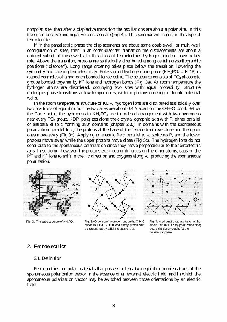
If in the paraelectric phase the displacements are about some double-well or multi-well configuration of sites, then in an order-disorder transition the displacements are about a ordered subset of these wells. In this class of ferroelectrics hydrogen-bonding plays a key role. Above the transition, protons are statistically distributed among certain crystallographic positions (‘disorder’). Long range ordering takes place below the transition, lowering the symmetry and causing ferroelectricity. Potassium dihydrogen phosphate (KH2PO4 = KDP) is a good examples of a hydrogen bonded ferroelectric. The structures consists of PO4 phosphate groups bonded together by K+ ions and hydrogen bonds (Fig. 3a). At room temperature the hydrogen atoms are disordered, occupying two sites with equal probability. Structure undergoes phase transitions at low temperatures, with the protons ordering in double potential wells.
In the room temperature structure of KDP, hydrogen ions are distributed statistically over two positions of equilibrium. The two sites are about 0.4 Å apart on the O-H-O bond. Below the Curie point, the hydrogens in KH2PO4 are in ordered arrangement with two hydrogens near every PO4 group. KDP, polarizes along the c crystallographic axis with P, either parallel or antiparallel to c, forming 1800 domains (chapter 2.3.). In domains with the spontaneous polarization parallel to c, the protons at the base of the tetrahedra move close and the upper ones move away (Fig.3b). Applying an electric field parallel to -c switches P, and the lower protons move away while the upper protons move close (Fig 3c). The hydrogen ions do not contribute to the spontaneous polarization since they move perpendicular to the ferroelectric axis. In so doing, however, the protons exert coulomb forces on the other atoms, causing the P5+ and K+ ions to shift in the +c direction and oxygens along -c, producing the spontaneous polarization.
2. Fer roelectr ics
2.1. Definition
Ferroelectrics are polar materials that possess at least two equilibrium orientations of the spontaneous polarization vector in the absence of an external electric field, and in which the spontaneous polarization vector may be switched between those orientations by an electric field.
Fig. 3b Ordering of hydrogen ions on the O-H-O bonds in KH2PO4. Full and empty proton sites are represented by solid and open circles
Fig. 3a The basic structure of KH2PO4 Fig. 3c A schematic representation of the dipole unit in KDP: (a) polarization along c-axis. (b) along –c-axis, (c) the paraelectric phase

4
2.2. Phase transitions
Most ferroelectric materials undergo a structural phase transition from a high-temperature nonferroelectric (or paraelectric) phase into a low-temperature ferroelectric phase (figure 2). Transition into a ferroelectric state may be of the first or second order. In second-order phase transition of spontaneous polarization changes continuously and for first-order transitions is discontinuous. Barium titanate is an example of a ferroelectric with a first-order phase transition and lithium niobate, LiNbO3 is a ferroelectric with a second-order phase transition.
For the simplest uniaxial case where the polarization (P) occurs only in one direction, and if all stresses are zero and the non-polar phase is centrosymmetric then we can write Gibbs free energy density as
2 4 631 21 0 ( )
2 4 6g g T P P P
αα α= + + + (2.2.1)
For simplicity in first- and second-order ferroelectric transitions only coefficient α1 is assumed to be temperature dependent. A simple temperature dependence which will satisfy requirements for the minimum in the free energy above and below TC, for continuity of the free energy at the transition temperatures is the linear temperature dependence in the form
1 0( ) /T T Cα = − where C is a positive constant. α3 must be positive for stability reasons (g1
cannot become −∞ as P → ∞ ). The order of the phase transition so depends on the sign of α2. The transition is of second order for α2 > 0 and of first order for α2 < 0.
2.2.1 Second order ferroelectric phase transitions
The second order phase transition is by the definition transition that has first derivatives of the free energy continuous but discontinuous second derivatives.
When we are expanding potentials such as in (2.2.1) we have to remember that Landau theory of a phase transition becomes invalid as temperature approaches critical point (second-point phase transition). The basic problem is that an expansion of the thermodynamic potential about critical point is usually not valid because a second-order transition point is a singular point of the thermodynamic potential (this is not the problem in first order phase transition because critical point is not a singularity). However, in ferroelectrics this critical region of Landau breakdown is extremely small and is quite difficult to observe. The reason for that is the long-range nature of the electric dipolar forces which are responsible for the ferroelectric transition.
If we minimize 1g g EP= − we get
3 511 2 3
gE P P P
Pα α α
∂= = + +
∂(2.2.2)
For P=0, the material is in the paraelectric phase. In the ferroelectric phase, for 0P ≠ and if we do not have electric field (E=0), (2.2.2) gives spontaneous polarization P
22 2 1 32
3
( 4 )2
Pα α α α
α− + −
= (2.2.3)
Because 22 1 3α α α? we can expand square root and we obtain
2 010 2
2 2
( ) , 0
T TP T T
Cα
αα α
−= − = − < > (2.2.4)
A solution for P must satisfy the condition for the stability of the ferroelectric phase below TC. (g1 < g0(T) and 0P ≠ ) and the condition that g1 = g0(T) above TC. One can easily verify that

5
this is indeed the case for the solution given in (2.2.4) if T0 = TC. Equation (2.2.4) gives two possible orientations of P (+P and -P) as required by the definition of ferroelectricity. With this information for P(T) it is now possible to calculate the temperature dependence of the permittivity
22 41
1 2 32
13 5
gP P
Pα α α
ε∂
= = + +∂
(2.2.5)
In paraelectric phase P = 0 and equation (2.2.5) becomes identical to the Curie–Weiss law. In the ferroelectric phase 0P ≠ and in the vicinity of the transition temperature the term with the fourth power of polarization in (2.2.5) may be neglected because the spontaneous polarization is very small. From (2.2.4) and (2.2.5) we find the permittivity below the phase transition. The permittivity near the phase transition is then
01 0
01 0
1
1
2 2( )
C
C
CT T T
T TC
T T TT T
αε
α
= > = −= − = − < =
−
(2.2.6)
2.2.2. First order ferroelectric phase transitions
Similar relations may be derived for ferroelectrics with the first-order phase transition if α2 is negative. Or we can change 2α α→ − (where α is positive) then we get
2 4 6311 0 ( )
2 4 6g g T P P P
αα α= + − + (2.2.7)
First-order transition (without field E) takes place when g1-g0 and its first derivative with respect to P are both zero. Then we get this two equations (where P=Pc is critical polarization because it happens at transition T=TC)
2 40 3( )0
2 4 6C
c cT T
P PC
αα−− + = (2.2.8)
2 403
( )0C
c cT T
P PC
α α−
− + = (2.2.9)
If we solve this system of equations we find T0 and spontaneous polarization at phase transition (T=TC)
2
03
316C
CT T
αα
= − (2.2.10)
2
3
3
4c CP T Tαα
= = (2.2.11)
We can also get reciprocal permittivity below and above TC.
2 403
( )13 5
T TP P
Cα α
ε−
= − + (2.2.12)
First we have to get temperature dependence for spontaneous polarization P from3 51
1 3 0g
P P PP
α α α∂
= − + =∂
(2.2.13)
and we find solution2
32
3 3
16 ( ) /2 4
CT T CP
α ααα α
+ −= + (2.2.14)

6
If we than expand square root and put equations (2.2.10) and (2.2.14) in (2.2.12) we get reciprocal permittivity for ferroelectric phase and for paraelectric phase (Pc = 0) we substitute (2.2.10) into (2.2.12) and find
2
32
3
( )38
1 4( )3
16
CC
CC
T TT T
CT T
T TC
αααεα
−+ <= − + >
(2.2.15)
We see that reciprocal permittivity is finite but discontinuous at TC and the ratio of slope (1/ ) /d dTε immediately below TC to that immediately above TC is -8. Schematic
representation for spontaneous polarization and permittivity for first- and second-order transition are shown on figure 1
The paraelectric phase may be piezoelectric (change in polarization when mechanical stress is exerted on piezoelectric material) or nonpiezoelectric. The symmetry of the ferroelectric phase is always lower than the symmetry of the paraelectric phase. Some ferroelectrics, such as barium titanate, BaTiO3, undergo several phase transitions into successive ferroelectric phases. The transition into a ferroelectric phase usually leads to strong anomalies in the dielectric, elastic, thermal and other properties of the material and is accompanied with changes in the dimensions of the crystal unit cell. The associated strain is called the spontaneous strain, xS. It represents the relative difference in the dimensions of the ferroelectric and paraelectric unit cells. So if the system spontaneously polarizes, it will spontaneously strain through the electrostrictive effect. Some changes that can occur in a ferroelectric material which transforms from a paraelectric cubic into a ferroelectric tetragonal phase are illustrated in figure 2.
Figure 1. Schematic temperature dependence of the dielectric permittivity ε and spontaneous polarization PS for (a) a first- and (b) a second-order ferroelectric

7
2.3. Ferroelectric domains and domain walls
Above we discussed macroscopic changes that takes place when we go from paraelectric to ferroelectric phase. Now we are interested in processes on microscopic scale. First we will talk about domain structure.
The spontaneous polarization in a ferroelectric crystal (or a grain in a ferroelectric ceramic) is usually not uniformly aligned throughout the whole crystal along the same direction. To avoid too general discussion we take as an example lead titanate, PbTiO3. Lead titanate is a perovskite crystal which transforms from a nonferroelectric cubic to a ferroelectric tetragonal phase at 490 0C. Perovskite crystals have the general formula ABO3where the valence of A cations is from +1 to +3 and of B cations from +3 to +6. As shown in figure 4, the structure may be viewed as consisting of BO6 octahedra surrounded by A cations. Most of the ferroelectric materials that are of practical interest have perovskite structure and many form a solid solution with PbTiO3. The spontaneous polarization in PbTiO3 lies along the cT-axis of the tetragonal unit cell and crystal distortion is usually described in terms of shifts of O and Ti ions relative to Pb. In the ferroelectric phase the crystal is spontaneously strained with T C Ta a c≤ ≤ where aT and aC are the a-axes of the tetragonal and cubic unit cell.
Fig. 2. Illustration of the changes in a ferroelectric material which transforms from a paraelectric cubic into ferroelectric tetragonal phase with temperature. Such a phase transition is observed in PbTiO3 and BaTiO3. The permittivity curve represents data is measured on a BaTiO3 ceramic. The arrows show possible directions of the spontaneous polarization (in two dimensions). The unit cell is represented by a square in the cubic phase and rectangle in the tetragonal phase.
Fig. 4. The perovskite structure ABO3, shown here for PbTiO3 which has a cubic structure in the paraelectric phase and tetragonal structure in the ferroelectric phase.

8
The six directions (including positive and negative orientations) along the three aC-axes of the cubic cell are equivalent, and the spontaneous polarization may arise with equal probability along any of them when the crystal is cooled through the ferroelectric phase transition temperature. The directions along which the polarization will develop depend on the electrical and mechanical boundary conditions imposed on the sample. The regions of the crystal with uniformly oriented spontaneous polarization are called ferroelectric domains. The region between two domains is called the domain wall (figure 5). The walls that separate domains with oppositely orientated polarization are called 1800 walls and those which separate regions with mutually perpendicular polarization are called 900 walls (figure 5). Because the cT and aT axes in a tetragonal crystal are different, the angle between polarization directions on each side of a 900 domain wall is slightly smaller than 900.
Ferroelectric domains form to minimize the electrostatic energy of depolarizing fields and the elastic energy associated with mechanical constraints to which the ferroelectric material is subjected as it is cooled through the paraelectric–ferroelectric phase transition. Onset of the spontaneous polarization at the transition temperature leads to the formation of a surface charge. This surface charge produces an electric field inside the body, called a depolarizing field Ed, which is oriented oppositely to PS (figure 6a,6b). The depolarizing field may be very strong (on the order of MV m-1) rendering the single-domain state of the ferroelectric energetically unfavourable. The electrostatic energy associated with the depolarizing field may be minimized if the ferroelectric splits into domains with oppositely oriented polarization (figure 6a) or if the depolarizing charge is compensated for by electrical conduction through the crystal or by charges from the material surrounding (for example from the atmosphere or the electric circuit to which the material is connected). Splitting of a ferroelectric crystal into domains may also occur due to an influence of mechanical stresses, as shown in figure 6a. Assume that a part of the PbTiO3 crystal is mechanically compressed along the (100) cubic direction (figure 6a; stress is exerted only on one part of crystal, not on whole) as it is cooled through the phase transition temperature. To minimize the elastic energy, the long cT –axis of the tetragonal cell will develop perpendicularly to the stress. In the unstressed part of the crystal, polarization may remain parallel to the direction of the stress. The domain walls in PbTiO3 may therefore separate regions in which polarization orientation is antiparallel (1800
walls) or perpendicular (900 walls) to each other. Both 900 and 1800 walls may reduce the effects of depolarizing electric fields but only formation of 900 walls may minimize the elastic
Fig. 5. Illustration of (a) 1800 and (b) 900 ferroelectric domains and domain-wall regions in a tetragonal perovskite ferroelectric. The schematic change of polarization across the domain wall is shown for a 1800 wall in (a). Tetragonal distortion in (b) is exaggerated.

9
energy. A combination of electric and elastic boundary conditions to which a crystal is subjected as it is cooled through the ferroelectric phase transition temperature usually leads to a complex domain structure with many 900 and 1800 walls.
Domain walls which differ in orientation to the spontaneous polarization vector are called ferroelectric domain walls and those which differ in orientation to the spontaneous strain tensor are called ferroelastic domain walls. In PbTiO3, 1800 walls are purely ferroelectric because they differ only in the orientation of the polarization vector. 900 walls are both ferroelectric and ferroelastic as they differ both in orientation of the polarization vector and the spontaneous strain tensor.
The types of domain walls that can occur in a ferroelectric crystal depend on the symmetry of both the nonferroelectric and ferroelectric phases of the crystal. In the rhombohedral phase of lead zirconate titanate, Pb(Zr,Ti)O3, the direction of the polarization develops along the body diagonals (direction (111)) of the paraelectric cubic unit cell. This gives eight possible directions of the spontaneous polarization with 1800, 710 and 1090
domain walls. Ferroelectric domain walls are much narrower than domain walls in ferromagnetic materials. Observations with transition electron microscopy show that domain walls in ferroelectric thin films are on the order of 1–10 nm.
Fig. 6a. Formation of 900 and 1800 ferroelectric domain walls in a tetragonal perovskite ferroelectric, such as PbTiO3. The deformation of the crystal in the domain-wall region due to the formation of 900 walls is exaggerated for the sake of picture clarity.
++
++
++
++
+
++++
++
+
_
_ _
_ _ _
_ _ _
_ _ _
_
_ _ _
Ed
P
Fig 6b. Schematic representation of depolarization field. This field arises due to uniform polarization inside the body.
x
y
+ + ++ + ++ + ++ + ++ + ++ + ++ + ++ + +
d
d
l z
x
Fig. 7 Fig 8.

10
2.4. Domain walls
In this section we study the size of domain walls, variation of polarization and the energy of domain wall for special periodic case shown on figure 7.
First we write free energy density (g) for domain wall (not the whole domain). It is composed of even powers of polarization, dipole interaction energy (wdip) and deformation of wall (wdef)
2 2 4 41 20 0( ) ( )
2 4 dip defg P P P P w wα α
= − + − + + (2.4.1)
where higher powers in expansion of P were neglected. It’s more convenient do write energy per unit of area of the wall (σ) as
2 2 4 41 20 0( ) ( )
2 4 dip defa
P P P P w w dxα
σ = − + − + + ∫ (2.4.2)
a) Dipole interaction energy (wdip)The magnitude of dipole moments in the domain wall changes, therefore we have to consider the dipole-dipole interaction. The energy of interaction between dipole µi and the field caused by all other dipoles µj is given by
( ) ( )dip i ij j i i ij j jj
w P x P xµ α µ β α β= − = −∑ ∑ (2.4.3)
where αij is determined by the distance and the angle between the dipoles and βi is constant of proportionality ( ( )i i iP xµ β= ). If we approximate summation with integral and assume that αij=α(xi-xj) decreases quickly with distance (|xi-xj|) we can expand this function around µ(xi) and get
' '' '''0 1 2 3( ) ( ) ( ) ( ) ( )dip i i i i i iw P x f P x f P x f P x f P xβ ≈ − + + + (2.4.4)
The first term in expansion is already present in g, so we only have to change α. For symmetry reasons it is obvious that P(x) is odd function of x (if the origin is in center of domain wall). Since '( ) ( )P x P x and '''( ) ( )P x P x are also odd functions their integrals in (2.4.2)over x vanish. So the dipole interaction energy per unit of volume is (let us also change f2 to f/2)
''( ) ( )2dipf
w P x P x= − (2.4.5)
b) Deformation energy of wall (wdef)When system spontaneously polarizes it causes deformation of the unit cell. It can be
shown [2] that relative deformation (or spontaneous strain) is equal to the square of the polarization (Fig. 2) 2x QP∆ = (Q is electrostrictive constant). So in the wall we have
2 20( )x Q P P∆ = − . More precisely, strain is a consequence of electrostriction ij ijkl k lx Q P P= .
Because the deformation energy is related to square of strain 2defw x∝ ∆ we only have to
renormalize coefficients α1 and α2 in g.Now we can write the energy of the wall with renormalized coefficients ( 1 aα → ,
2 bα → ) and with dipole interaction energy from (2.4.5)
2 2 4 2 ''0 0( ) ( )
2 4 2a b fP P P P PP dxσ = − + − −
∫ (2.4.6)
In order to determine P(x) and thickness of the domain wall we have to minimize (2.4.6) with respect to P

11
23
20 2f P
aP bPP xσ∂ ∂
= ⇒ + =∂ ∂
(2.4.7)
Solution of the differential equation is
02( ) tanh xP x Pδ
=
(2.4.8)
where P0 is 0 /P a b= − (remember that b is negative) and δ is defined as the thickness of the domain wall
2fa
δ = (2.4.9)
Inserting (2.4.8) and (2.4.9) into (2.4.6) and integrating from -δ /2 to δ /2 we get domain wall energy per unit of area
20c aPσ δ= (2.4.10)
where c is constant from integration ( 0.2c ≈ ). Values of σ for two types of crystal are written in table 2.
2.5. Domains
The purpose of this section is to determine the width of domains for the structure shown on figure 7. To get the width we first have to calculate energy of crystal. This is composed of two parts: energy from the surfaces of domain, which causes the depolarization field called depolarization energy and the surface energy of the domain boundary that was calculated in previous section (2.4.10).
a) Depolarization energy Depolarization energy for periodic case can be calculated as it is done in appendix. Solution gives us energy proportional to d/l [3]
20*
EP d
W Vl
ε= (2.5.1)
where d is domain width, l crystal thickness, P0 polarization of domain, ε* is constant and V is a volume of crystal. For some more complicated structures we can find depolarization energy from
1 21 2
0 124EW dVdVr
ρ ρπε
= ∫ ∫ (2.5.2)
where ρ1 and ρ2 are the total charge densities in volumes dV1 and dV2 separated by r12.
b) Wall energy is
WW S Vdσ
σ= = (2.5.3)
where σ is energy per unit of area from (2.4.10).Minimizing the whole energy with respect to volume gives a value of the domain width
1/ 2
20
( )0
*E WW W l
dV P
σε
∂ += ⇒ = ∂
(2.5.4)
For the 1800 domain walls in BaTiO3 the above analysis leads to an estimate for wall thickness 1 nmδ : in reasonable agreement with experimental results which indicate a width of less than 5 nm. The wall energy (2.4.10) is then 20,01 /J mσ : .

12
Domains of width greater than (2.5.4) are suppressed by the depolarization field while domains smaller than this are suppressed by the wall energy. When the crystal thickness decreases until domain width approaches the domain wall thickness the depolarization energy can no longer be minimized by domain formation and ferroelectricity may cease to exist.
Estimates for other domain structures are listed in table 2. It is noticeable that the domain wall thickness is only few unit cells wide in sharp contrast with ferromagnetic domain walls. This difference is due to the fact that magnetic exchange energy is much larger than the elastic energy and slow rotation of the magnetization vector occurs over hundreds of unit cells. While the vector magnetization of a ferromagnet has a constant magnitude, the ferroelectric polarization decreases to zero at the center of domain wall.
2.6. Ferroelectric hysteresis loop and polarization switching
The most important characteristic of ferroelectric materials is polarization reversal (or switching) by an electric field. One consequence of the domain-wall switching in ferroelectric materials is the occurrence of the ferroelectric hysteresis loop (figure 9). At small values of electric field, the polarization increases linearly with the field amplitude ( i ij jP Eχ= where χij
is susceptibility tensor). This corresponds to segment AB in figure 9. In this region, the field is not strong enough to switch domains with the unfavourable direction of polarization. As the field is increased the polarization of domains with an unfavourable direction of polarization will start to switch in the direction of the field, rapidly increasing the measured charge density (segment BC). The polarization response in this region is strongly nonlinear. Once all the domains are aligned (point C) the ferroelectricity again behaves linearly (segment CD). If the field strength starts to decrease, some domains will back-switch, but at zero field the polarization is nonzero (point E). To reach a zero polarization state the field must be reversed (point F). Further increase of the field in the negative direction will cause a new alignment of dipoles and saturation (point G). The field strength is then reduced to zero and reversed to complete the cycle. The value of polarization at zero field (point E) is called the remanent polarization, PR. The field necessary to bring the polarization to zero is called the coercive field, EC. The spontaneous polarization PS is usually taken as the intercept of the polarization axis with the extrapolated linear segment CD. Strictly speaking, in polycrystalline materials true spontaneous polarization equal to that of a single crystal can never be reached and it is more correct to speak of saturated rather than of spontaneous polarization.
Table 2 adopted from [4]

13
An ideal hysteresis loop is symmetrical so that +EC = -EC and +PR = -PR. The coercive field, spontaneous and remanent polarization and shape of the loop may be affected by many factors including the thickness, the presence of charged defects, mechanical stresses, preparation conditions, and thermal treatment.
The mechanism of polarization switching has been studied in detail for many bulk and thin-film ferroelectrics [1]. The problem is clearly very complex and there does not seem to be a universal mechanism which would be valid for polarization reversal in all ferroelectrics.
2.7. Motion of domain walls
Polarization reversal can be accomplished either by the growth of existing domains antiparallel to the applied field, by domain-wall motion, or by the nucleation and growth of new antiparallel domains (Fig. 10). The domains can grow either along the polar direction or by sideways motion of 1800 domain walls. The relative importance of these processes depends on the material and the applied field, although it appears that for most ferroelectrics with the polar axis normal to a plate-shaped crystal, sideways motion of 1800 domain walls is preferred to forward motion. Direct measurement of the domain-wall motion and switching current showed that the wall velocity in BaTiO3 varied as
/ Ev v e δ−∞= (2.7.1)
where δ is a constant up to 300 V/cm which appears to depend on the defect of the crystal.
Fig. 10. Probable sequence of polarization switching in ferroelectrics: (a) nucleation of oppositely oriented domains, (b) growth of oppositely oriented domains, (c) sidewise motion of domain walls and (d) coalescence of domains. Black and white areas have different orientation of polarization.
Fig. 9. Ferroelectric (P–E) hysteresis loop. Circles with arrows represent the polarization state of the material at the indicated fields. The symbols are explained in the text.

14
It was recognized very early that, since a domain wall is generally only a few lattice spacing thick, then the energy required to move the wall through one lattice spacing is comparable to the wall energy itself. Since the energy gained in moving the wall by one lattice constant is much smaller than the wall energy, this kind of wall motion is unlikely. The only physical model which seems to explain the experimental data is that the observed sideways wall motion is caused by the nucleation and two-dimensional growth of reversed step-like domains on existing 1800 walls (figure 12,13).
Hayashi [5] has developed a general formulation for the kinetics of domain wall motion from which it is possible to determine absolutely the rate of nucleation and domain wall motion in the low- and high-field regimes. We will only show the exponential law (2.7.1)which is valid for velocities of ranges of 10-7cm/s to 10 cm/s. We will assume that wall moves through nucleation mechanism and that the rate controlling process is the nucleation of steps along a wall, and not the subsequent growth of the nucleated steps. The energy change consequent on the formation of a nucleus of volume V and domain wall area A can be written as
2E sW A W P EVσ∆ = + − (2.7.2)the third term is the electrostatic energy of the nucleus in the applied field. The polarization and local field E within the nucleus are assumed to be uniform. The assumption is also made that 1800 domain wall is very thin.
The shape of nucleus which is the most energetically favourable is triangular (figure 12). For this shape the depolarizing energy can be calculated from (2.5.2) and is found to be
2 2 2
0
2 2lnS
EP c a a
Wl ebπε ε
= (2.7.3)
where lattice constant b comes into the expression as the lower limit of r12 and other constants are shown on fig 12 (l is the height of nucleus). The total energy (2.7.2) can now be written as
2 2 22 2 1/ 2
0
2 22 ( ) ln 2S
sP c a a
W c a l P Ealcl eb
σπε ε
∆ = + + − (2.7.4)
The dimensions of critical nucleus a* and l* can be determined from conditions
0 and 0 W Wa l
∂∆ ∂∆= =
∂ ∂(2.7.5)
and are* *1 2
K Ka l
E E= = (2.7.6)
Fig. 12.. Schematic drawing of a triangular step on a 1800 domain wall. The applied electric field is parallel to the spontaneous polarization on the left-hand side of the figure
Fig. 13. Schematic drawing showing the growth of triangular-shaped nuclei on the steps formed by earlier nucleations

15
where K1 and K2 are constants composed of geometrical constants and spontaneous polarization (we are only interested on field dependence). Inserting equations (2.7.6) in (2.7.4)we get
1W
E∆ ∝ (2.7.7)
The rate of domain nucleation is proportional to exp(-∆W/kT). So we demonstrated that wall velocity is indeed of form (2.7.1), where δ is temperature dependent 3 1/ 2/P Tδ ε∝ . If the nucleation rate is the rate-controlling process of polarization reversal then is also in agreement with the experimentally measured switching time ( / Et t eδ
∞= ). However, the situation is more complicated than this for the general case. For instance nuclei can grow on the growing steps of earlier nucleations as shown in figure 13. In general it is not obvious whether the wall velocity depends on the nucleation rate or the growth velocity of the steps. Nucleus could also form somewhere in the ferroelectric and not necessary on the domain wall, but probability for this is extremely small it was calculated that an energy of about 108 kT is needed to nucleate such a domain [6]. The transition to a power law at high fields is due to the fact that two-dimensional triangular nuclei which are important at low fields cannot nucleate at high fields since the critical dimension a* in the a-direction becomes smaller than a lattice constant. Instead, one-dimensional nuclei are formed with their length along the polar axis and these grow in a two-dimensional manner.
2.8. Importance of ferroelectrics for application
The physics of ferroelectrics that originated in 1921 has nowadays become one of key branches of the solid-state physics. The background theory for ferroelectrics is very well known so the main research today is focused on their applications. Ferroelectric materials find applications in a wide area of fields such as industrial process control, environment monitoring, communications, information systems, medical instruments…
The application of ferroelectrics can be divided in four main areas: (a) piezoelectric detection, (b) pyroelectric detection, (c) memory devices, (d) electro-optic modulators
(a) Piezoelectric materials are a class of materials which can be polarized by application of a mechanical stress - direct piezoelectric effect, or they change their dimensions (they contract or expand) when an electric field E is applied to them - converse piezoelectric effect. Some of the best piezoelectrics materials are ferroelectric. Piezoelectrics are used as sensors -using direct piezoelectric effect (e.g. pressure sensors) or piezo motors (actuators) – using converse piezoelectric effect.
(b) Pyroelectric materials change their spontaneous polarization when temperature is changed. This phenomena can than be used for detection of temperature changes. Thermal pyroelectric detectors have broad spectral response – from microwaves to X-rays and they can even detect temperature changes caused by particles. They also have the useful features of room-temperature operation, simplicity of construction and operation, and do not require an external bias field. However, in contrast with other thermal detectors, the pyroelectric current response depends on the rate of change of temperature rather than temperature it self.
(c) The bistable polarization of ferroelectrics can be used for binary memory system the same way as the bistable magnetization of ferromagnets. The memory is non-volatile and does not require a holding voltage. To record information the polarization may be reversed or reoriented by an application of an electric field greater than the coercive field. The information can be retrieved with electrical means or with optical means using electro-optic effect. Although with initial difficulties in earlier years (well defined corrective field and

16
square hysteresis loops) today there has been progress on a field of ferroelectric RAM (FeRAM). This type of RAM has advantages over other types of memories such as flash memory – it has faster access time (75 ns) and much lower power requirements – that makes it a perfect memory device for mobile phones.
(d) Another important application of ferroelectrics is the fact that they can modulate light. Such modulators are required for most optical communications systems where the high-frequency laser carrier allows large-information bandwidths. Modulators use linear electro-optic effect and in recent times they also exploit the quadratic electro-optic effect.
Many applications today are realized with ferroelectric ceramics which could be in form of bulk, texture, layer or thin films. There has also been a lot of research in liquid crystals which posses electrical properties similar to those of ferroelectrics. In recent years there has been rapid rise of activities for the integration of ferroelectric thin films in commercial devices. The latest developments in application of ferroelectric films are FeRAMs, actuators and sensors in micro electromechanical systems, for mobile communications… There has also been invention of ferroelectric nanotubes made from strontium bismuth tantalate, barium titanate and lead zirconate titanate (PZT). Because these nanotubes are piezoelectric insulators they can be used in various applications: for ink-jet printing, medical nano-syringes and for deep trenching in Si DRAMs.
Although the theoretical work on ferroelectrics is more or less finished, there is extensive research on a field of applications. In fact, the application of ferroelectrics is more and more required especially because of rapid developments in communication technology and in recent years there are also new perspectives in nanotechnology and other areas.
Appendix
We will show how to calculate the depolarization energy of crystal with periodic structure from figure 7 [7]. Let coordinates be as shown on fig. 7. Because we do not have any free charge we are solving Laplace equation
2 ( , ) 0x zψ∇ = (A.1)
where ψ is electrostatic potential ( E ψ= −∇ur
). From the boundary conditions at z=0
1 2 1 2 and z z x xD D E E= = (A.2) we find the solutions for Ex and Ez
0
0
0
0
4cos( )
4sin( )
nkzx
n odd
nkzz
n odd
PE nkx e
PE nkx e
πε
πε
−
∈
−
∈
= −
=
∑
∑(A.2)
where k=π/d.Only the first term n=1 contributes most to the integral of energy (if we would do a
precise calculation then result with n=1 would have to be multiplied by factor 1.05). Energy is then
22 0 0
0 2 200
1612 2
PWE dz
dy kεε
εεπ ε
∞
= =∫ (A.2)
and finally we can write the energy as2 2 2
0 0* *d
W P d y P Vl
ε ε= = (A.5)
where all constants are combined in ε*.

17
References
[1] Lines M., Glass A.M., Principles and Applications of Ferroelectrics and Related Materials (Oxford 1979)
[2] Damjanovic D., Rep. Prog. Phys. 61 1267–1324 (1998)[3] Mitsui T., Furuichi J., Phys. Rev. 90, 193 (1953)[4] Zhirnov V. A., Zh. eksp. teor. Fiz. 35, 1175 (1958) (Sov. Phys. JETP 8, 822 (1959))[5] Hayashi M., J. Phys. Soc. Japan 33, 616 (1972)[6] Miller R, Winrich G. Phys. Rev. 117, 6 (1960)[7] Kittel C, Phys. Rev. 70, 965 (1946)