fermi national accelerator laboratory - internal...
TRANSCRIPT

Fermi National Accelerator Laboratory
Shielding Calculations for
Multi-TeV Hadron Colliders
A. Van Ginneken and P. Yurista Penni National Accelerator Laboratory P.O. Box 500, Batavia, IL 60510 USA
and
C. Yamaguchi KEK
Oho-machi, Tsukuba-gun, 305 Japan
January 1987
FN-447
0103.000 (SSC-106)
0 Opereted by Unlveroltles Research Association Inc. under contract with the United States Department ol Energy

SHIEi.DING CALCllATIONS
FCR
WLTI-TeV HAlJlON <Xlll..IDmS
A. Van Ginneken aDd P. Yuri.st.a. Fermi.lab, Batavia, n., 60610, l5A
aDd
C. Yamaguchi KEK, Cb::>-machi, Tsukuba-gun, 305 Japan
Jamiary 1987

1
I. Introduction ........................................................... 6
II. Particle Production in Colliding Beams ................................ 10
III. Intezpretation of Results ............................................. 14
N. Results ............................................................... 19
V. Progr:ams .............................................................. 29
VI. Graphs ................................................................ Fl
Entries in tables refer to both figure rnvrber and page number. Since there is exactly aie page to each figure, refereru::ing is made easier by re-nuoi>ering the pages of secticn VI to match page and figure rovrber. To distinguish fran text, page romi>ers of this secticn a.re preceded by a letter F. A bl.aDlc table entry means the cmxespxiding gra?J. is not included.
A. HAIRlNS. FIXIID TARGET
Star Densities
I I C cct/sl+ Al Fe Pb IE, TeVI I I I I I I ICl>*IJdrlJdzl Cl>IJdrlJdzl DEi Cl>IJdrlJdzl Cl>IJdrlJdzl Cl>IJdrlJdzl 1--1-1-1-1-1-1-1-1-1-1-1-1-1-1-1-1-1 I 5 I 1 I I I 6 I I I 111 141 I I 191 I I 241 I I 1--1-1 I 1-1 I 1-1-1 I 1-1 I 1-1 I I I 10 I 2 I 4 I 5 I 7 I 9 I 101 121 151 171 181 201 221 231 251 271 281 1-1-1 I 1-1 I 1-1-1 I 1-1 I 1-1 I I I 20 I 3 I I I 8 I I I 131 161 I I 211 I I 261 I I
+ cct means caicrete; sl means soil *(]> denotes ccn~ plots (of star dellsity), Jdr and Jdz refer to radial and l.a!gibxlina,1 integrals, DE denotes ccn~ plots of dose equivalent
Sta.rs outside Block
I I Fe I cctlsll IE, TeVI I I I I Cl>lr=olz=olr=olz=ol 1-1-1-1-1-1-1 I 5 I I I I I I 1-1-1 I I I I I 10 I I 301 311 321 331 1--1-1 I I I I I 20 I 291 I I I I

2
F.nergy Density
I I C cct./sl I Al Fe Pb IE,TeVI I 1------------1 I CPlfdrlfdzl CPlfdrlfdzl CPlfdrlfdzl CPlfdrlfdzl CPlfdrlfdzl 1--1-1-1-1-1-1-1-1-1-1-1-1-1-1-1-1 I 5 I 341 I I 391 I I 441 I I 491 I I 541 I I 1--1-1 I 1-1 I 1-1 I 1-1 I 1-1 I I I 10 I 351 371 381 401 421 4.31 451 471 481 501 521 531 551 571 581 1--1-1 I 1-1 I 1-1 I 1-1 I 1-1 I I I 20 I 361 I I 411 I I 461 I I 511 I I 561 I I
Ca~c Beam Loss. Hadrcn Dose
I ccntimJOOS dip::>le* I beam pipe* I I I I I IE,TeVI inside! middle! ootside I side I I I I I I I I I CPIJdrl CPIJdrl CPIJdrlJdzlC-PIJdrlJdzl 1--1-1-1-1-1-1-1-1-1-1-1 I 5 I 591 I 621 I 651 I I 691 I I 1--1-1 1-1 1-1 I 1-1 I I I 10 I I 611 I 641 I 671 681 I 711 721 1--1-1 1-1 1-1 I 1-1 I I I 20 I 601 I 6.31 I 661 I I 701 I I
*in a tunnel
Stars in Air
lccnt. lblpipel I I dip::>le I stsect I IE,TeVI I I I I Jdr I Jdr I 1--1 I I I 5 I I I 1-1 I I I 10 I 74 I 75 I 1--1 I I I 20 I I I

3
B. MUJNS. FIXED TARGET
Muai. Beam in Soil
IE,TeVlz,restlx,restlz,xSP*lpg,CP,I 1--1 I I I I
PgVSZ
.011 76 I 84 I 88 I 92 96 --1 I I
.031 77 I I --1 I I
.1 I 78 85 I 89 I 93 gr --1 I I
.3 I 79 I I -I I I
1. I 00 96 I 90 I 94 98 -I I I 3. I 81 I I --1 I I 10. I 82 fJ7 I 91 I 95 99 1--1 I I 120. I 83 I I
::scatter plot of z, x where µ canes to rest ,Cant.our plot of energy density
Catastrq:hlc Beam Loss. Muai. Dose
Hadrcll Cascade in• soil
IE,TeVI CPIJdrlJdzl 1-1-1-1-1 I 5 11001 I I 1-1-1 I I I 10 1101110311041 1--1-1 I I I 20 11021 I I
Loss en Beaupipe in a tumiel
IE,TeVI CPIJdrl 1-1-1-1 I 5 11061 I 1--1-1 I I 10 110611001 1--1-1 I I 20 11071 I

4
O:l!ltinuous Dipole. Beam Frame
I beam an inside beam an outside I beam in middle I I I I I IE,TeVI inside I up .It down I rut.side inside louteidel inside loutl I I I I I I I 1-1 I I CPlfdrlfdzl CPlfdrlfdzl CPIJdrlfdzl CPlfdrlfdzlfdrlfdzl CPIJdrlJdzl CPI 1--1-1-1-1-1-1-1-1-1-1-1-1-1-1-1-1-1-1-1 I 5 11091 I I I I 11171 I 11221 I I I 11281 I I I 1--1-1 I 1-1 I 1-1 I 1-1 I I I 1-1 I 1-1 I 10 1110111211131 111511161118112011211 11241125112611271 113011311 I 1--1-1 I 1-1 I 1-1 I 1-1 I I I 1-1 I 1-1 I 20 11111 I 11141 I 11191 I 11231 I I I 11291 I 11321
Ccnt:imlous Dipole. Magnet Frame
I tm inside I tm outside I I I I I IE, TeVI inside I inside I I I I I I I Cl'lfdrlfdzl Cl'l/drl/dzl 1-1-1-1-1-1-1-1 I 5 11331 I 11381 I I 1-1-1 I 1-1 I I I 10 1134113611371 114011411 1-1-1 I 1-1 I I I 20 11351 I 11391 I I
C. ITTJ IDING ~. HAillONS
Collisicn Hall Geanetry
I I side wall I back wall IE,TeVI I I I I Cl'IJdrlfdzl Cl'l/drlfdzl 1--1-1-1-1-1-1-1 I 5 11431 I 11471 I I 1--1-1 I 1-1 I I I 10 I 114511461 114911501 1--1-1 I 1-1 I I I 20 11441 I 11481 I I

5
Beam Pipe in Soil
IE,TeVI CPl/drl/dzl 1--1-1-1-1 I 5 11511 I I 1--1-1 I I I 10 I 115311541 1--1-1 I I I 20 11521 I I
0. ITTJTDINGJEAMS. ™
Ilo.mst<r"eam Penet.ratian
I wall at. I I I I I all I IE, TeVI 2Can I 100n I 25Qn I I I I I I 1-1 I I a>l/drl a>l/drl a>l/drl/dzl 1--1-1-1-1-1-1-1-1 I 5 11551158116111641167117011731 1--1-1-1-1-1-1-1-1 I 10 11561159116211651168117111741 1-1-1-1-1-1-1-1-1 I 20 11571160116311661169117211751
Collisicn Hall Gecmet.ry
I I-· 1blr+ I IE,TeVl-1-1 I I a>I a>I 1--1-1-1 I 5 11761 I 1--1-1-1 I 10 I I I 1--1-1-1 I 20 117711781
6
I. INIROru::n:ON
The present. volume is JOOSt. easily described as an extension
of an earlier similar effort~ The extension is ma.inly to higher energies
but. it. also includes colliding beam s:i.Jwlat.ians as well as DDJOIJ.
product.ic:n and transport.. There is also a larger variety of gecmetries
presented. But. the ?JillOSe rema.:ills the. same: to provide a collect.ion of
gra?Js which may serve as a rough. guide in shielding applications . De
tailed designs selckm reseni>le the idealized cases analyzed here and
deserve specific caipit.a.t.ion with. particular at.tent.ion to any suspected
weak spots . The gra?Js included here are intned to go no further th.an
to farm a useful starting point. in design llOI"k. Such an approach is al
ready quite effective at. 1 TeV and below and will beccme even mre so at.
higher energies where shielding costs are even larger.
The choice of standard energies (5, 10 and 20 TeV> reflects
the raDge of collider energies presently cont.euplated and all<:MB for
m.:xiest. extrapolation out.side th.is r?Dge. For fixed target. results up to
1 TeV refs. 1 and 2 may be consulted. As in refs. 1 and 2, all results in
th.is volume (except t.hcse perta.ini.ng to •nu:n beau&") use the Lt:ll.te Carlo
code CASIM~ Where ,-0 induced elec:t.rc:magnet.c showers are included as,
e.g., in DIXll product.ion or in energy deposit.ic:n, they are s:i.Jwlated with.
the AEGIS' code. Predict.iais of CASIM (plus AEGIS where applicable) for
target. beating, induced radioactivity and absorbed dose in the sub-TeV
regime agree quite well with. experiment.~ 1...:1.kewise CASIM results caipare
well with. a set. of absorbed dose measurements taken ~ide thick shields
for a variety of beam loss and shielding gecmetries~ The full extension
of CASIM into the lllllt.i-TeV danain requires considerable m:xli:ficat.ians to
both. particle product.ion and particle transport. m.:xiels. This extension is
presently only partly c:aipleted.

7
Particle producticn in CASIM for the fixed target (parti
cle-nucleus) case is still described by the Hagedorn-Ranft mdel 7 plus a
high Pr caip:ment a;ad a 10\9' energy nucleon caip:ment~ This mdel cc:mpa.res
well with experiment in the sub-TeV range~ No such cc:mpa.risans exist for
the extended (>1 TeV) m::xiel but at least no gi:ossly unphysical features
seem to appear. &me trends are worth noting: (1) the average fast
charged particle llllltiplicity increases too slOW'ly with energy. e.g .. for
copper it rises fran 13 at 1 TeV to about 17 at 40 TeV. Fran CffiN
Collider results a la;rger llllltiplicity is to be expected.; (2) the
nannalizaticn of the Hagedorn-Ranft producticn cross secticns becanes
scmewha.t worriscme at the higher energies. In CASIM leading particle
spectra are IlOI111alized to a total of exactly two such particles and picn
spectra are IlOI111alized to enforce overall energy cmservaticn. Both fac
tors stay within 1~ of unity in the 3 to 1000 GeV range. fuwever the
leading particle IlOI111alizaticn factor cl.:illils to 1.17 at 40 TeV while far
picns it falls to 0.46 <using again copper as an exanple).
This does not mean that the typical shielding calculation
is invalidated by these defects. Such calculaticns usually sum aver many
generaticns and the mechani em of energy cmservaticn <built into the
m:xleD ensures scme self~auecticn far reasaiably small deviaticns fran
reality. Far exanple, by underestimating its llllltiplicity, a !.bl.te-<:a.rlo
interacticn at 40 TeV necessarily produces particles with higher average
energy, which in mm produce JICre particles in the next generaticn than
would be the case if the correct llllltiplicity were predicted. It should
also be eq:basized that these deficiencies of the m:xlel are limited to
the highest mergi.es and beru:e affect cnly the first fevr generaticns. In
fact, predicticns of CASlM en star deosities and broad beam energy depos
iticn in the TeV danain agree wen 1° with results of other codes which
E111Floy producticn m:xlels of JICre recent vintage. Also, while an :iJ!Froved
particle producticn m::xiel is clearly desirable, scme care llllBt be taken
in its farnul.a.ticn to assure agreement with experiment at the highest
available mergi.es while maintaining the predictive power of CASIM in the
sub-TeV danain. This might be best Ulldertakm when JICre detailed results
of the CElN Collider and Fermilab Teva.t.rcn are available.
8
Hadral productien by colliding beams is described by an
~irica.1 m:xiel based rostly an Fermi.lab data, a.long with sane CERN C.ol -
lider results and ccnstrained by conserva.tien laws. This IIrJdel is out
lined in Sec. II. Prcupt DIJOll production is described by an E311Firica.l
fo:rmula.11 which expresses DIJOllS as a. fraction of pions produced as a.
f=tien of Feynman~. This formtla. is based en 1m1ch lower energy work
and is used here ma.inly out of ccnvenience. Ncnetheless, the forlmlla. does
feature a. slCM' increase in D1lCll ulll.tiplicity with incident energy as is
expected fran increased cha.rm and bottcm (plus perhaps top) meson produc
tien though it is not a.t~ to quantitatively justify this pa.rticula.r
ra.te of increase.
Particle t..raDsport in the ulll.ti-TeV regime differs signifi
cantly fran tha.t a.t. lower energies due to the increasing :i.nportance of
bremsst.rahlung and direct pa.ix productien a.s a. source of energy loss and
aDgUla.r diffusien. The basic ~ and :iq>lanentatien into CASIM is
described elsewhere~2 Results presented here involving 111xn t..raDsport a.re
obta.:ined with the updated code. Predicticns of this code a.re in excellent
agreanent with data. of Kepp et a.1~3 en the energy dist:ributien of a.
120 GeV D1lCll beam trazlsmi.tted ~ a 9.& thick ircn ta.rg-et. Hadral
dose and sta.r density ca.lculaticns a.re perfOI11led. with a s:iq>le extecsien
of the old code which treats energy loss due to bremsst.rahlung and pa.ix
productien en an a~ basis and neglects the associated aDgUla.r
diffusien. This is justified for this type of calculatien since cnly the
llDSt energetic particles a.re affected by this and since productien angles
will teed to be lllJCh larger than the deflectien incurred over cne
interact.:i.al leogth. Energy depositicn at large radii is ca.lcula.ted in
similar fasbicn.
By ccntnst, energy depositicn ca.lculaticns over radial
distances of the order of typica.l beam sizes anticipated a.t the colliders
(a.s lCM' a.s 50 µm) DJSt. include an accurate descriptiai. of these new sour
ces of aDgUla.r diffusiai.. The reasc:n is tha.t for such small beams the
radial dependence of the energy density varies rapidly over distances

9
caiparable to the beam size. This has i.Iqlortant applicatiCl!lS in the de
sign of beam dunJlS and the problem of radiaticn induced quenching in
superconducting magnets. Calculatians of this type a.re also 11Dre likely
to be affected by the details of the pa.rt.icle producticn m:xiel. Therefore
they are not included in the present volume.
The basic CASlM code is reascnably well documented3 and the
recent update to the (!lllcc) transport pa.rt. is described elsewhere~ 2
Below, in Secticn II, the pa.rt.icle m:xiel used to simlla.te colliding beam
interactiCl!lS is described. Secticn III deals with presentation and
interpretaticn of results, while the results theu&elves a.re briefly
reviewed in rl. Secticn V cent.a.ins SCllle infOima.ticn en the codes used in
preparing this volume.

10
II. PARTICLE moru:;n:QN IN ITT I IDING BEAMS
The particle production rwd.el used in the simula.tian of
colliding beams is a. siq>le pa.rametriza.tian based an ext.rapola.tian of
lower energy experimental results. As is the ca.se for the Hagedozn-Ranft
rwd.el used in the fixed target pa.rt, leading particles, i.e., final sta.te
particles which ma.y be identified with the incident particles, a.re dis
tinguished fran particles newly crea.ted in the collision. For the present
purpose leading particles a.re al.ways protaJs or neutrals. Elastically
scattered (colliding) protaJs will a.lJOOSt al.ways either rana.in within the
beam or else lea.ve the beam aperture a.t 1a:rge distances fran the inter
acticn reg:icn and a;re therefore ignored. The m:re energetic lea<ling particles will typically al.so ram.in in the beam pipe far a. ccnsiderable
di.staru:e. Hence leading particle producticn need not be trea.ted in utm:>st
deta.il. <Large azig.1.e elastics and leading particles al.aig with other
produced particles 111.lSt be removed by saoe collima.ticn scheme so a.s to
protect the ckJimstream supercaiducting magnets. This type of problEm is
not ccnsidered here. It is al.so possible tlla.t such a. collima.tor, pa.rticu
la.rly c:oe intercepting a 1a:rge fracticn of these particles nea.r the in
teracticn reg:icn, ma.y recpire shielding far perSCEDel or enviralmenta.l
protecticn. This is straigly depecdsn.t en the detailed design of the
interacticn reg:icn and therefore likewise anitted here.)
A. Leading Particles
leading particles are divided into a diffractive and IlCll.
diffractive o "P nent.. Gc:J11li anos14 uses the pa.rametrizaticn
(1)
where the first. term is the diffractive pa.rt. To ccnfaan to the trea.tment.
of the produced particles <see below) the radial scaling variable, Xlt•

11
the particle's energy :in the center of mass eJql!'essed as a fraction of
its maximum ldnema.tically allowed value, replaces the oore usual Feynman
x used by Goulianos. For the present work these should be cc::mpletely
:interchallgeable. Fran the coherence cooditian14 the diffractive part llDJSt
vanish around ,~.9. It is therefore assumed that
(2)
where the sec:aid equality follows fran continuity at ,=0.9. The value of
A follows fran nmmaliz:illg eqs. (1) aDd. (2) to im.ity. The behavior of
doldxa when, awroaches its ldneuatic limit is not well described by
eq. (1) . Note that , can be eJqlI'eSsed as
(3)
where s is the square of the total energy :in the center of mass aDd. Mx is
the :invariant mass recoiljng aga:inst the lea<Hng proton. The data16 at
loir Mx <high Xg) m:,, that do/dxa starts at zero at ~P +M,. aDd. (an
average) increases relatively rapidly ~ a series of resooances :in
Mx• to a m;;pdmnn wbereup::n it the declines :in accordance with eq. (1) .
For our present plIJXlSe the caiplicated behavior of da/dxa Deal" threshold
is sim.J.lated by assumillg that it rema.:ins constant between
~ = 1-0.6/s (4)
(couespniing to Mx=1.22 GeV> aDd. :x;-z (where Mx~). Bela.~ eq. (1)
is assumed to hold.
The pT dep«rlence of the leading particle cross section is
assumed to be of the type
do/dp~ IX exp(-bp~ (5).
For the ncn-di.ffractive part b is set to 5 <GeV/c)-2 . For the diffractive
part b=2b.1~4 where bel. pertains to elastic scatter:illg Deal" the forward
directicn aDd. is taken fran the parametrizaticn of Block aDd. Cabn~6 It is
assumed that diffractive protons do not uodergo cba.rge exchange but that
zxn-diffractive protons ccnvert :into neut.rems with a probability of aae
half. This is :in ~ accord with data of F.ngl.er et al~ 7

12
Upon llllltiplying eqs. (1) and (2) by ~ and integrating
over the entire ~ range one obtains the leading particle center of mass
inelasticity, i.e., the fraction of the total energy carried off by lead
ing particles. This ecpal.s about 0.43 with little variation over the 5 to
20 TeV colliding beam energies explored here.
B. Pians and Kaoos
As in CASIM, the lea<iing particles' energy is subtracted
fran the total energy and the rema.inder is shared am::iog the produced
particles. Not every particle species is represented in the silllllated
collisians. In CASIM the produced particles a.re s:i.q>ly the three types of
pians. For the colliding beams, partly because the cross secticn forlllllae
a.re 1DJCh s:i.q>ler, kaClls are included as well. In eitiler scheme otiJer
particles can always be added with::m. having to recast the entire m:idel.
The :i.nvatiant. cross secticn for r and K producticn is assu-
med to be
(6)
where A and n depend en particle type: A<r*)~1 and A<K*)=A(r*)/9, and
n(r+)=3.5, n(r-)=4.2, n~=2.8, n<l\)=5.2. Since soall angle particle
producticn has not yet been studied in detail a.t the <ElN Collider these
parameters a.re taken <scmewbat l<X>Sely) fran Fermi.lab da.ta. of A. Brenner
et al.~ 8 and J. R. Jcl!nsm et al.~9 and with the A<r*) fixed by energy
canservaticn. The pT parametrizaticn is based en the work of Amison et
al.~0 with the value of m based Cll E!lttnpola.ticn of <ElN rm and Collider
da.ta.. For the preswt work m=6.5 for fJ<2 and m=9.0 for fJ>7 (fJ being the
center of mass rapidity) and m is taken to vary linearly in between. The
usual :rule of taking the r 0 <K°) producticn cross secticn to be cne half
the sum of the charged rOO cross sectians is followed.
This s:i.q>le m:xiel predicts a. charged particle inela.sticity
of about 0.77 and a. rms pT is about 0.07 GeV/c both with little variation

13
crver the range of ../s fran 10 to 40 TeV. The charged particle multiplicity
varies fran 43.9 to 48.3 over this range. This is likely to be an under
estimate.
Eq. (6) as well as its counterpa.rt.s for leading particles,
eqs. (1) arui <2), permit relatively s:inple Monte Carlo selection schemes
to be :inplemented, whether selecting proportional to the Illlltiplicity or
to the inelasticity.

14
III. INTIEffiETATIDN OF R&SULTS
A. Dose an::!. star Densities.
A freqiently used procedure (followed, e.g., in Ref. D is
to present star densities above sane predet.ennined cut-off. The staru:la;rd
cut.-off is 0.3 GeV/c~1 <Above this va.lue cross sectians vary only slowly
with energy an::!. this permits a nnmher of shart.cuts in the program which
could not be ma.:illtained at lCMeI" m::menta. The precise va.lue of the cut.
off is scmewbat a.rbit.ra.ty but cansiderable convenience is derived by
adheriDg to the 0.3 GeV/c standard.) These star densities may then be
ccnverted to dose assum:i.Dg the presence of an eqiilibrium m::mentum spectrum of the participating hadrals. Such an eqiilibrium spectrum (with a
spectrum shape insensitive to location) prevails anly at sufficiently
large depths an::!. radii. At lCMeI" values of r an::!. z a cai.versicn factor
based en an eqiilibrium spectrum would underestimate the dose . In these
cases ane lll1St use a locaticn depelldent canversicn factor~
This procedure is included in a number of experimental
tests6 of CASIM an::!. yields quite satisfactory results. It is however
limited to shields ce1•1osed of soil an::!. caic:rete for which the eqiilibri
um spectrun shape is reaem..bly well established. For shields cc:qiosed of
ircn or heavier elammts awlicaticn of a eimi Jar procedure1 ' 22 reqiires
great cauticn. Because of large fluctuatians in ~ cross sectians
as a funct.icn of eamgy for these elements aDd. because of the absence of
hydrogen it reqiires deeper penetraticn to establish an eqiilibrium spectrum. Furthmm::lre while an eqiilibrium spectrum, e.g., in soil, may be
expected to be reaemably robJst with respect to small cbaDges in <soill cc:qiositicn this is not necessarily so for the heavier shields. Perhaps
llJ:)St, illp:irtantly the E11Firical basis of the procedure, which is quite
well established. for soil an::!. cau::rete, is lacking.

15
The rule adopted here is to present results in tenns of
dose equivalent (rem) for soil and concrete aru:i in tenns of sta.r densi
ties for all other materials. The dose is calculated by applying a sta.r
to-dose canversicn factor, which depends an particle type aru:i an m::mentum, within the Mente-Carlo. For low energy neutrons this factor is iden
tical to the cne of Ref. 1 thereby guaranteeillg agreement with the above
menticned procedure in regians where low energy neut.rais predani nate.
Closer to the incident beam there a.re additicna.lly significant cantribu
tians due to r 0 initiated sbcMers and due to charged particles. For can
pa.risan, the results for a solid ccncrete (soil) cylinder a.re presented
both ways.
The limitaticn of reliable dose calculatians to soil or
ccncrete is in practice not a severe cne. .Alm:>st all accelerator shield
illg relies en an ooter layer of soil or CCllcrete for neut.rm a.ttenua.tic:n.
A rule of thuni> is that alx:ut 1m of CCllcrete <radially) is required to
establish an equilibri\Jll. spectrum.
Hadrcn producti.c:n <mostly lc:7W energy neut.rans) by electro
nmgnetic cascades is not included in any of the calculatians. Cmpared to
direct productic:n this seems quite inefficient, but the fracticna.l energy
spent en elect.ranagnetic showers <~ at. 20 TeV in ll"aJ) increases llJ:D:)
tonically with energy and this guarantees that eventually this mechanism
will beC<JDe significant.
Expressing dose-ecpivalent in rem <m lieu of sievert> may,
regrettably, :incaMmietXe sane but it offers at lea.st sane continuity
with ref. 1. Since ran is still widely used and the ccnversic:n is tri
vial, there Deed. be no further apology. b'e serious is a. likely furore
revisicn of cpili.ty factors, pa;rt,icularly if the calculated dcse-eqrl.
valent has m:xre than a:ie significant carpxtent which could undergo dis
simi J a.T revisiais. Forbma.tely, in m:ist applica.tiais a. da!rinant e< "\<Dent
<usually either llllCllS or lc:7W energy neutrals) may be readily identified
and a revised dcse-ecpivalent can then be evaluated.

16
Ref . 1, am:mg many other sources, contains sane hints and
recipes on convert:ing calculated results of the type presented here into
irore inmediately useful numbers. For convenience sane often encountered
conversion factors are reproduced here with the caveat that these are not
universally agreed upcn.
In cmcret.e and in regions where the cascade is sufficient
ly developed the ~ ~ rate may be estimated fran the star den
sity:
350
or 1.5 10-6 rad
or 9.0 10-6 rem.
In .inll. and in regiais where the cascade is sufficiently
developed star density may be cai.verted into np ege n.t& result:ing fran
induced radioactivity. Far the "MAst case• of infinite irradiatien time, zero cool:ing time and en cent.act: 23
To protect against ~ w;a.ter actiyatjm. the criterien
is a limit:ing caicent.ra.tien of radioactivity in drinking water. It is the
practice at Fepnjlah to translate this into a limit:ing mnrber of stars
per incident protcn produced in \m.CCllU"Oiled soil. 'Ibis, in tmn, dic
tates size and shape of beanrlimps. There is no unique ccnversien factor
fran radioactivity caicent.ra.tien to stars per incident protcn. 'Ibis de
pends en the expected beam intensity as well as the (usually poorly
}apm) transport of the radioactivity produced a.round the dimp to the
water source. Based en very caiservat.ive a:gunents a typical Fermilab
beanrlimp admits 0.015 stars/incident protcn in \m.CClltrolled soil. In
ccnu-ast to the ccnversien factors above this mnrber is cnly meant as an
illust.rat.ien and is not far direct use in design calculatiais.

17
B. Scaling.
For hatJ:lgen.eoUs shields of roughly the same a.tJ:m:i.c c~i
tian sin:ple scaling rules24 ma.y be applied to adjust for different densi
ties. Since the basic pa;rameters (interaction length, stopping JX"l'I&",
particle productian characteristics, etc.) vary anly slowly with a.tJ:m:i.c
ma.ss these scaJJng rules have a rather wide raiige of application particu
larly where roogh answers suffice. In the present study these roles are
applied over a. very narrow raiige viz. , to inter-Tela.te calculations for
wet soil, dry soil and cancrete. Given their similar caq:iosi tian the
scaJJng should be nearly exact. For canvenient access it appears useful
to repeat here sane farm.llae of Ref. 24 upcn which the scaJ i ng (illustra
ted in a large mmt>er of the graphs) is based.
Star densities scale as:
s..,<pcrclp..,) = sc<}c)(p,/pc)a m where r is the positicn vector within the shield and p is the density.
The subscripts identify different materials, e.g., c far ccmcrete and w
far wet soil with assumed densities pc=2.4 gcm3 and p.,,=2.24 gcm3 . In
eq. m it is assumed that Sc is explicitly calculated and that S.., is
derived by scaling, i.e. ,
S..,<1.07ltc> = 0.813•Sc<}c) (8).
Far star density result.a presented in the f= of cant.our plot.a the above
eqmticns sbar b::llr both r and z axes llllSt be recalibrated a.s well haw a.s
the cart.ours an to be relabelled.
Dose scales as
(9)'
i.e. with the axes to be recalibrated a.s far star densities but with the
centaurs relabelled differently. Star densities integrated over radius .. I(z) = I s<1>2rrcir
0
(10)

18
obey the scaling rule
(11).
Note that in all cases presented here (i.mlike eq. (11)) the upper limit
is actually sane finite radius (problem boundary). Use of the scaling la.w
requires that the problem radius be large.
The integrals of star density over depth (z) shown in the
graphs refer to
z !(r) = 2rr f Sci-)dz (12).
0 I(r) follows the same scaling la.w as !(z), shown in eq. (11) and with the
same caveat about the upper limit of integraticn. The factor 2rr in
eq. (12), while sanewha.t uncanventicna.l, facilitates subsecpent integra
ticn of !(r) over r.
Far heterogeneous shields scaling laws are obviously less
applicable. Yet cne may identify instances where these laws may be used
tJyugti generally to a lesser degree of ~ticn. The case of a beam
striking a ta;r:get in an otherwise enpty tunnel provides a suitable illus
traticn. Far exanple, cne may seek to apply scaling far different tunnel
wall materials while keeping everyth:ing else identical. If the tunnel
wall surface is thought of as a source of particles at ccnstant r but
widely distributed in z then it is clear that scaling does not apply in
the z-directicn. H::Mever the integral over all z can still be scaled
provided radial distances are measured fran the tunnel wall:
(13).
Far a cave, scaJing may be applied far the integral over r in the z-di
recticn provided the daninant ccnt.ributicn enters through the back wall
rather than through the tunnel wall. Certain problems, though in prin
ciple heteroge11eoiJS, will yield reasaiably ~te answers when trea
ted as b::m:igeneoos far scaling purposes, e.g., the m:xre energetic DJJalS
emanating fran a mil.ti-TeV protcn beam loss in a magTiet inside a tunnel
may traverse several lan of soil before stowing and little accuracy will
likely be lost by scaJing en the basis of the b:m:lgeneoos soil case.

19
N. RESULTS
A convenient tabulation of all results appears in the Table
of Contents. Far ease of reference the entries in this listing refer to
the page number of the carrespand:ing graph. t.bst of the graphs a.re readi -
ly interpreted but, where appxqniate, sane caimenta.ry is provided in
this section. The results a.re divided into : W hadron dose aod <B) 111Ja1
dose fran fixed target initial interactiC11S, <C> hadron dose aod <D) 111JC11
dose fran col1iding beam initial interactiC11S, where "initial" indicates
that effects of the cascades induced by these interactiCllS a.re included.
A. Had:rcn Dose. Fixed Target.
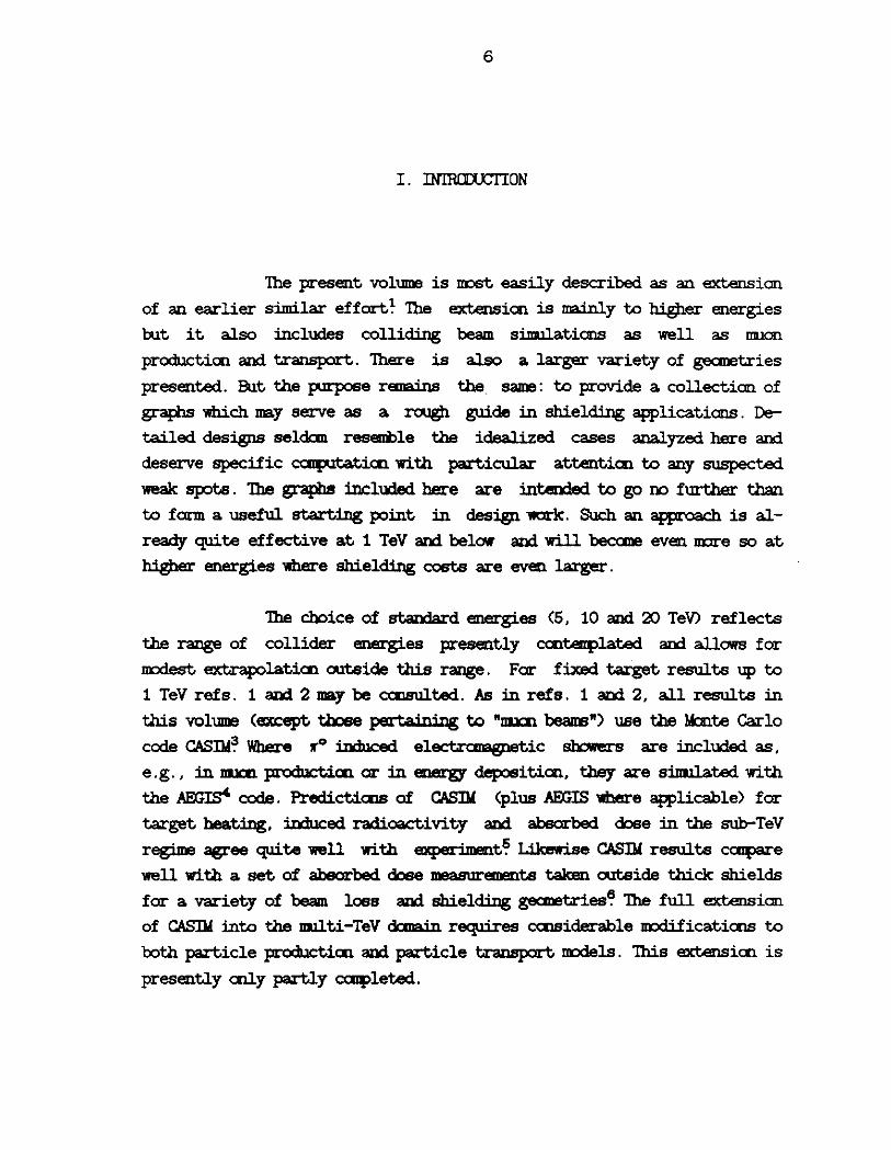
Fig'S. 1-3 present ccntour plots of star density far 5 , 10
aod 20 TeV prot.CllS incident en a solid (i.e .• hcm:ge11.eous) ca.rb:n cylin
der. Fig. 4 sbaRs radiaJJy integrated star densities as a function of
depth (z) aod fig. 5 laigi.t>JdinaJly integrated star densities as a frmc
tien of radius (r) , also far ca.rbcn aod far the same incident protcn
energies. Fig'S. 6-10 repeat this seq.ience of grapis far caicrete aod
si.m.ll.t.aneously, via the scaling of Sec. m, far soil. Fig'S. 11-13 a.re
i.so-dose plots far the caicrete/soil case, obtained fran the same calcu
latiC11S as the star densities but converted to dose-equivalent by a fac
tor which dspellds en particle type aod rrrmen:tum. Fig'S. 14-28 show star density results far al1mrim1D1, ircn aod lead. Far all cases the beam is
parallel to the cyl 1nder axis aod has a Gaussian distribution indepen
dently in x aod y with "x=a7=1 nm.
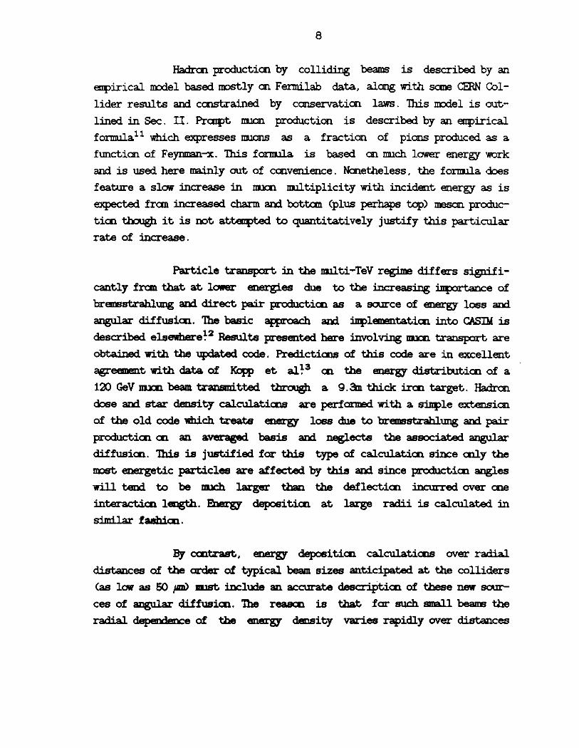
Fig'S. 29-33 deal with radioactivity induced in soil outside
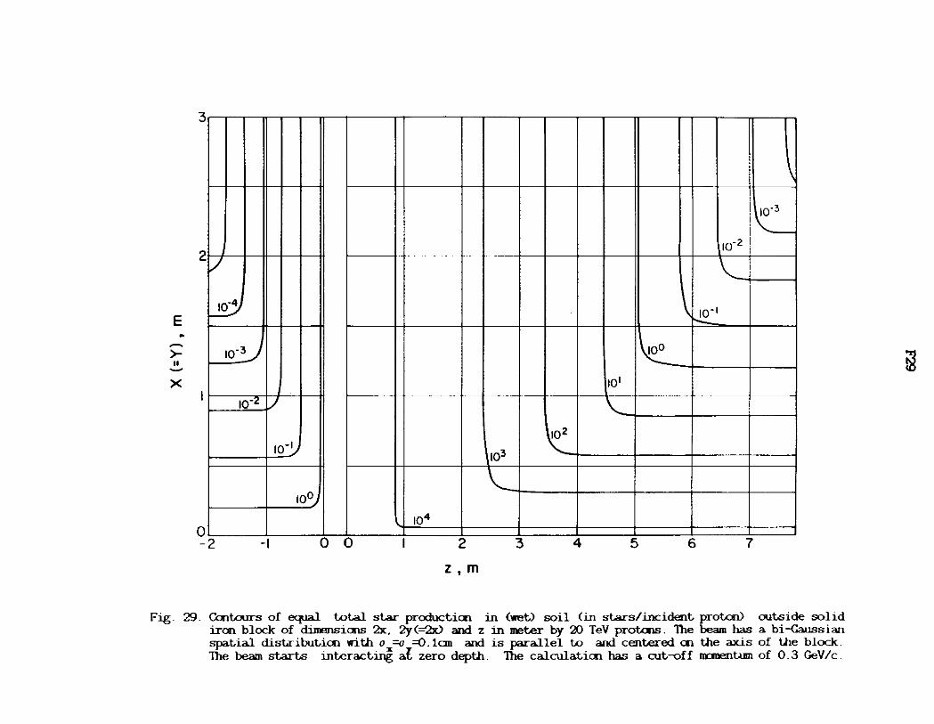
thick targets. Fig. 29 plots ccntours of equal total star productien in
soil outside an ircn block by 20 TeV prot.CllS incident en axis . Forward
aod backwa;rd directiCllS a.re sham separately. Note that these results
20
pertain to a. block, not a. cylinder as for the sta.r densities, with x<=y)
indicating the half width of the block. As can be seen in fig. 29 a.11
iso-sta.r cant.ours q.ri.ckly asSUDle their a.synptotic form pa.ra.llel to the x
and z a.xes. This is expected since little can be gained by a.dcling to the
sides when escape is predaninantly fran the back and vice versa.. Since
not IIDlch inf=tian is canta.ined in the "corners" of the cant.ours, the
rest of the plots, figs. 30-33, show only the loca.tian of the a.synptotes
as a. fimctian of x or z. 1hus fig. 30 exhibits the tota.l number of sta.rs
produced outside an infinitely wide, sani-infinitely long iron block,
i.e., the block has finite length in either the positive or negative z
directic:n. Fig. 31 plots the tota.l mmiler of stars produced outside of an
infinitely lang irc:n target which is likewise infinitely wide for either
z>O or z<O but has finite width :in the other ha.lf-spa.ce. Figs. 32 and 33
are the =esp:llding graphs for caicrete/soil. Results for z<O are less
well established and CCEServative interpreta.tic:n is advised. These fig
ures ma.y be useful a.s starting va.lues in, e.g., optimizing the outer
dimensicns of a. beam duop. Althoogh the star density cent.ours canta.in
essentia.lly the same infanna.tien, the results presented :in figs. 29-33
a.re m:ire caivenient to use a.s well a.s expected to be m:ire accurate, espe
cia.lly at large x or z. This is a. result of a different M::n~lo
strategy enployed: (1) :in caiplting the mmiler of sta.rs :in soil due to
escapees the •scare• associated with each such escapee is the average
tota.l mmber :in stars, a mJ!i>er not subject to fluctuatic:n, and (2) col
lisic:n length biasing is introduced to ensure that types and spectra of
the escapees are sufficiently sanpled. This strategy can be adapted to
inh Iii geneoos taz'get8 a.s well a.s to m:ire caiplex: gecmetries.
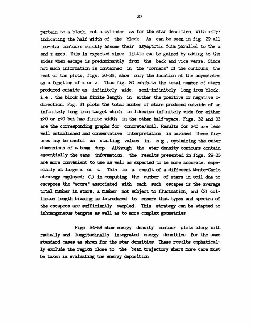
Figs. 34-58 show eos:rgy density cent.our plots alang with
radially and laigi.tndinally :integrated energy densities for the same
staDda'rd cases a.s shown for the star densities. These results eqihatical
ly exclude the regien close to the beam trajectory where m:ire care JIDlst
be taken :in evaluating the energy d.epositien.

21
Calculations of the hadron dose resulting frcm catastrophic
beam loss appear in figs. 59-72. Calculations of a m:ire specialized na
ture such as these are m:ire useful, by virtue of a m:ire realistic gecme-
try, but at the same ti.me less useful since they are influenced by design
changes aru:l. since sane sinFlification in modelling beam loss, accelerator
gecmetry aru:l. magnetic fields is inevitable. Two gecmetries are included
here: (i) a contimlous, circularly curved dipole represented by a "C5"
magnet aru:l. (ii) a 1 IIDI thick beaapipe in a straight section, each enclo
sed in a 1.2 m radius <respectively curved aru:l. straight) tunnel. Beam
pipe, magnet alld. tunnel are assumed to be concentric. The ~ition of
the tunnel wall is assumed to be wet soil. Because the ma.in objective is
to determine the wall thickness needed far protecticn fran catastrophic
beam loss, the star density is evaluated in the tunnel wall cnly.
Design drawings of the cross-secticn of the dipole alaig
with a sketch of its reptesentaticn in the progi:am are shown in fig. 73.
An ideal magnetic field is assumed present in the gap. In all cases of
this study the central field is taken to be .§...Q Tesla.. This means that
far a ccntimlous dipole case (the cnly type ccnsidered here when a field
is present) the ring radius is adjusted far different beam nnnenta. Out
side the gap the field is obtained by interpolaticn fran arrays of its x
alld. y c• 11p nents specified en a rectangular grid with 0.25 inch spacings
coverillg the magnet cross-secticn~6 Also far the dipole case three beam
loss mdes are presented: (i) beam loss en inside of the beaapipe, i.e.,
towards the center of the ring, (ii) beam loss en outside alld. (iill mid
dle. The latter may be thniight of as resulting, e.g. fran beam-gas inter
acticn. In each mode the beam is assumed to interact precisely at z=O alld.
with its di.rect.ial tangential to the curving magnet. Far inside alld. out
side beam loss tbe beam is of infinitesimal extent in the horizontal
directicn alld. has a Gaussian spread of 0. 01 cm vertically. Far beam loss
in the middle the beam is assumed to be <=elated) bi-Qwssian with
ux=tJ7=-0.01 cm.
To obtain the a.z:imlthaJ. depetdence of the star density the
0 to ,. range (the problem is synmetric about the midplane) is divided
22
into three b:ins: 0 to ir/4, ir/4 to 3ir/4, and 3ir/4 to ir. Not unexpectedly
the azimuthal dependence is small enough to be ignored since the dose in
the tunnel wall is neut.ran daninated. The z ms for all cases is the
distance along the central orbit of the accelerator. Results for 10 TeV
are not shown since these are easily obtained by interp:>latian fran the 5
and 20 TeV graphs. The interesting second burr;> appearing for the case of
inside beam loss is due to particles crossing the apert=e which is geo
metrically favored in this case. The location of the peak is roughly
where the tallgent to the inside of the beaq>ipe at the interaction point
meets the beaiq:>ipe ance again an the outside, which is where neutral
seccn:laries are expected to land.
Figs. 74 and 75 shol1' the linear star density in the air of
the tunnel, which surrounds respectively a magnet and a bare beaiJFipe, as
a functian of distance fran the point of interactian. This serves as an
estimate of air activatian resulting fran beam loss. For the beaupipe
case the dose calculated in the backward directian is not shown since it
is both very small and very =ertain.
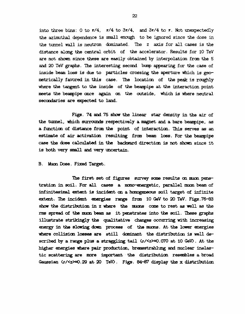
B. Mucn Dose. Fixed Target.
The first. set of figures survey sane results an lllJal pene
tratian in soil. Far all cases a ~ic, parallel lllJal beam of
infinitesimal extent is incident an a haoogeoeous soil target of infinite
extent. The incident energies range fran 10 GeV to 20 TeV. Figs.76-83
shol1' the distributian in z where the llllCllS cane to rest as well as the
nos spread of the m.xn beam as it penetrates into the soil. These graphs
illustrate str:ikingly the qualitative chaDges occurring with increasing
energy in the sl.olr.iilg dOlm process of the llllCllS. At the lORer energies
where collisian losses are still dani nant the distributian is well de
scribed by a range plus a st.rasgling tail (o/<z>=O.<:nO at 10 GeV>. At the
higher energies where pair producticn, bremsstrahlung and nuclear inelas
tic scattering are m::ire inplrtant · the distributian resembles a broad
Gaussian (o/<z>=0.29 at 20 TeV>. Figs. 84-87 display the x distribution

23
of moons caning to rest. Figs. 88-91 are scatter plots showing the densi -
ty of stopped moons as a function of radius and depth. Figs. 9'2-95 are
contour plots of the energy deposition density as a function of r and z.
For small r and z these results are not well resolved. Figs. 96-99 dis
play the linear energy density as a function of z alang with a breakrlown
of IIlllCIIl energy deposition mechanisms.
Figs. 100-104 pertain to lllJCllS generated by the hadron
cascade when a ~tic hadron beam enters a hcmlgeneous soil tar
get. While this has few inmediate applicatians it ma.y be of interest as a
limiting case, since the presence of any voids will generally increase
the DllCll flux. Also, without geanetric or other caiplicatians, it ma.y
serve as a test case, e.g., in caiparisan with other calculatians.
M::lre practical fixed target DllCll problems are addressed in
figs. 105-141. Mucn dcee fran catast.roph.ic beam loss an a beal!Fipe is
sham in figs. 105-108. The geanetry is the same as for the hadron case
but, because of the deep pen.et.ration by the lllJCllS, the bmnel length IJJJSt
Dt:1il be made explicit and is chosen to extend 1 km beyald the interaction
point. This is of the order of the length of a st.ra.i.ght section canteiir
plated for the SS::~6
The r-aining figures in this set deal with 111.lO!l. dose fran
catast.roph.ic loss in a cant.i TD'JCIJS dipole. Again the geanetry and magnetic
field description are identical to the hadron case. The presence of a
magnetic field aloog with the large distaoces involved and the curved
geanetry :introduce SC111e aui>iguity in the choice of reference frame to
analyze this problem. There are two obvious choices: (i) a "beam frame"
in which the z axis is taDgential to the accelerator and (ii) a "magnet
frame" where z is replaced by s, the distaoce alaig the central orbit.
Analyzing the same calculation separately in each frame is not necessari
ly an optimal procedure but it should produce an overview of the problem
fran which m::xre detailed calculatials can then depart.

24
Tue beam loss m::xie is idealized as in the hadron dose ca.1-
culations with the same distinction of losses on the inside, outside and
middle of the beaq>ipe. In contrast to the hadron case the muon dose
rates show a marked a.zimlthal dependence. An exhaustive treatment is not
at~ted, but figs. 100-141 present an overview as well as (hopefully)
the m::ire interesting cases. Note also tha.t results for beam frame aru:i
magnet frame overlap to sane extent at small z or s. Magnet frame results
a.re given aily for the a.zimlthal quadrant to the inside of the ring since
<D JJJJcn dose in the outside quadrant is better analyzed in the beam
frame 3lld (iD JJJJcnS can travel large distances by "clwmelling", i.e.,
being repeatedly reflected bebveen magnet aperture and return field. Fran
the latter viewpoint positive m.xms a.re scmewhat ID:lre interesting than
negatives by virW.e of <D having the proper guide field orientation in
the aperture where there is no eJOergy l06s aDd <iD being produced in
scmewhat larger mJri>ers by protcn iilduced cascades, particularly the m:ire
energetic JJJJcnS. Since positives reflect off the inside of the magnet
they a.re expected to leave the t=nel in t.hat directicn.
Laigitwlinally integrated energy density plots in the beam
frame have sane cantributi.cn at radii less than the tunnel radius which
is emitted in the figures for lack of s:inple interpreta.ticn, en account
of the curved gecmet.ry, and because this regicn is easier to analyze in
the magnet frame. This also applies just outside the t=nel wall.
c. Colliding Beams. Hadrcn Dose.
The idealized gecmet.ry of a collisicn ball used in the pre
sent calculatiais is shown in Fig. 142. Dimensiais a.re roughly tliose
given in ref . 26. A 1 nm thick beaapipe runs through the center of the
ha.ll. The protais a.re asSl.llled to collide at the origin and produce sec
co:laries according to the mdel of Sec. II. These particles in turn
interact. with nuclei in the beaapipe am walls according to the exteDded
Hagedorn-Ranft mdel. In additicn to the usual a.zimlt.hal symnetry there
is also reflecticn symnetry about the vertical center line. This is eoc
ploited in the calculatiais am also in the presentaticn of the results,
which cover cnly ha.lf of the interacticn regicn. This 111.lSt be borne in
mind when integrating results ove the entire regicn.

25
Results are given separately for the side wall and for the
back wall of the cylindrical hall in figs. 14.3-150. This geanet.ry provi
des a "worst case" since the hall will typically house sane apparatus,
e.g., a large detector, which provides significant shielding. Figs. 151-
154 show results for a=ther ext.reme: a beaiq)ipe surrounded caipletely by
soil. These results plus sane interpolation and ext.rapolation could pro
vide a useful starting point for a l!Dre realistic calculation.
D. Colliding l3eaDE. Mucn Dose.
Mucn dose calculatiCllB fran colliding beams sources are
primarily concerned with the deeply penetrating llJJCllS travelling along
the collision axis. The relevant gecmet.ry is that of the accelerator near
the interaction regiCllB and it straigly influences the relative :iJ!Fortance of decay versus pxcupt llJJCllS, since this is largely detem:ined by the
distance traversed. through voids by 11' and K produced in the collision. A
realistic calculation 'llOUl.d trace the produced particles through a rea
scnable ideal i zatian of the accelerator caqx:nents and thus ccupute for
each particle of the saq>le its appzopxiate decay probability into a
llJJCll, as well as keep track of scattering and any magnetic bending of
both produced particle and resulting llJJCll. Such an U!ldertak:illg is proba
bly warranted when the design of the machine is sufficiently frozen. Here
a llllCb. cruder app1'0ach is taken: the interact.ion is assumed to take place
in a void at a fixed distance fran a semi-infinite b::m:lgeneous soil
shield in which the llllCll energy deposition is analp:ed. The distance to the soil shield is taken to be respectively 20 m, 100 m and 250 m. The
20 m and 100 m represent the distance to the beginning and end of the
strcmgl.y focussing quadrupoles near the interact.ion region where sane of
the produced 11' and K are expected. to leave the ape; ture. The 250 m cor
respcn:is roughly to the distance at which the U.O beams re-enter their
separate aperbl:res~6 The main objective here is not to make quantitative
predictiCllB for the ~ but rather to explore the question of praIJ>t
versus decay llJJCllS for a reasmahle raog-e of decay lengths. Figs. 155-175
show results for the penetrating llJJCllS. The racli ally integrated plots
also contain a breakdawn an the llJJCll production mecharii !!IDB.

26
The final set of graphs pertain to mi= dose in the vicin
ity of the collision hall. The particle prcxiuction m:x:lel indicates that,
in an average event, a large number of soft hadrons are emitted. A>:.carr
panying these hadrals one expects sane llllOllS of caipa.ral:lle energies to be
present, resulting both fran praq:>t arui decay mechanisms. The diiferent
character of hadrcn alld llllOll absorption poses the question as to which
caip:sient determines the shield thickness. It appears that for the side
walls <figs. 176 am. 177) the nu:n dose already becanes caipa.ral:lle to the
hadrcn dose at a.round 2m of soil far the region nearest to the colliding
beams. At the far end of the hall this equi--dose thickness is about 4m.
Far the back wall <fig. 178) the hadrcn dose daninates eaq:>letely. The
collisicn hall gec:met.ry is the same as used to calculate hadron dose. To
obtain meaningful results in reasmal>le executicn times the selection of
hadrals alld pzaipt llllCllS in the colliding beams JlllSt be heavily biased
tan.rds those with larg-e Pr.
In the light of these results and of the uncertainty of the
producticn m:x:lel, especially for llllCll8, the side wall calculation might
be worth repea.t:i.Dg with different sets of assuq>tiCllS as a check on sen
sitivity of this result to the m:x:lel. .Another uncertainty about this
problem is gecmet.rical: to find a reasmably siDple gec:metry which ap
prax:illates a •worst case• fran the JDJal shielding point. of view. It has
been ascerta.ined by separate calculatiCllS (Dot explicitly included here)
that the rEllDVlll of the 1mD beanpipe chaDges the results very little,
i.e., the beaapipe's effect as an absorber of llllCll8 rougbl.y cmpensa.tes
for its effect as a source of neir lllJalS. This is not clear a priori, aDd.
it is also DOt clear that this will ccntimle to hold as the beaapipe' s
thickness is :illcreased, e.g., to simllate the presence of other
awa;ratus.

V. PROGRAMS
As mentioned in the Introductien the basic program used in
this work is CASIM supplemented by AEGIS far electranagnetic sha.vers, by
the eupirical. particle productien m:>del far colliding beams and by DDJOn
produ.ctien and transport. To generate the various results CASIM was cast
into several different versicns . The differences between any tll10 such
versicns not cnly reflect the presence (ar absence) of colliding beam ar
llllCE. beam si.mllaticns but also include different gecmetries, presence of
magnetic fields as well as binning, ncrmalizaticn and printing of the
results. This ucdus operandi, vis-a-vis the obvious alternative of canbin:ing everything into aie progi:am with m.lltiple q>ticns, is the result
of both necessity and ccnvenience. A single prqy;am alternative would
easily exceed. the N100 Kword limit at the ~ of the Femilab Caip.i.ter
Depa.rtmimt where DDSt of the developnent and debngg:ing was dale. Actual
running tcd: place aJm::>st exclusively en the FPS of the Accelerator Divi
sien where storage is m:xre than sufficient but where turn-arOU!ld far
sbart debugging runs might create a problem.
Any of the various versicns is available by cent.acting ale
of the Femilab autbcrs. The prqy;aus a.re all in FCRIRAN V and a.re tested
en both ~ and <VJiX equivalent.> FPS cc:aplters. libJt need ale ar m:xre
extra. files (e.g., 1auge ecmgy tables) as well as a data file. The codes
are not necessa.tily "user friendly" but all carry an introductory de
scripticn specifying where the ma.jar changes fran the stalJda.rd CASIM
occur and which files are referred to by the program. All such files as
well as sanple data files are likewise available. This work, especially
the ~. ma.y serve as a •meou• of "What is available as a suitable
starting point far further explaraticn.

28
CASIM VERSIONS FCR SSC SHIElDING STIJDIES
A. Fixed Target. Hadron Dose
CJS2. St..aDdard. CASIM. Ca!pltes star densities, rem dose and <a.t large radii only) energy deposition.
CSXl. Catastrophic beam loss in ccntinuous dipole placed in a <curved> tunnel ar of beanpipe in st."raignt secticn.
CAIR. Star density in air of omnel far catastrophic beam loss in ccntjrn!OIJB dipole ar beanpipe in st."raignt secticn.
B. Fixed Target. Muc:n Dose
lil.JP3. Muc:n beam in infinite, haqeDeous soil. Requires hisUlgraamir>g package, e.g. , KIC1RA ar HIDJ{.
QlJN. Muals fran catastrophic beam loss in cootirnnis dipole.
~. Muals fran catastrophic beam loss in st."raignt secticn.
c. Colliding Beams. Hadrcn Dose
Collisicn hall s-t.Iy. Calculates sta.r density ar rem dcse in side 'llllll or bade 'llllll .
D. Colliding Beams. Muc:n Dose
!RMS. Colliding beams in void. Varia.ticn of deca.y space is sim!lated by mveable wall. Includes ccntriWticn of badrcn cascades in soil.
NlRM. High Pr llllCllS in collisicn hall gecmet.Iy.
Q:mumicaticns about bugs, illprovements, new ar unusual awlica.ticns, etc.' with reference to the above codes will always 'be greatly 21¥ecia.ted.

29
Our tilaZlks to Igor Ba.ishev, IXlil Cossairt alld. Manfred lbf ert for helpful ccmnents en the manuscript, to Graciela Finst.ran for her care ccnc~ the presentatien of the graphs and to Angela Gonzales for the caver design.
1. A. Van G:imleken and M. Awschalan, "High Energy Interactions in Large Target.a•, Fermilab, Batavia, IL. (1975).
2. J. D. Cossairt, "A Collectien of C'J.SIM Calculations", Fermilab 'lll-1140 (1982).
3. A. Van G:imleken, "C'J.SIM. Program to Simllate Hadrcnic Cascades in atlk Matter•, Fermilab Flr272 (1975).
4. A. Van G:imleken, "AF.GIS. A Program to Calculate the Average Behavior of Electrcmagnetic Slx:Mers", Fermilab FN-309 (1978) .
5. M. Awschalan et al., Nucl. Inst. Meth. m, 235 (1975); M. Awschalan et al., Nucl. Inst. Meth. ~ 521 (1976).
6. J. D. Cossairt et al., Nucl. Inst. Meth. JSL 465 (1982) ; J. D. Cossairt et al., Nucl. Inst. Meth. ~ 504 (1985).
7. R. Hagedam, SuP,pl. Nuovo Cim., .a, 147 (1965); R. Hagedam and J. Ranft, &Jwl. Nuovo Cim., .2. 169 (1968); J. Ranft, "Secondary Particle Spectra According to the 'Illeimxlynami,cal Model. A Fit to Data Mea.sllred in p-Nucleus Collisicns", 'IUL-36, Karl Ma;rx Uliv., Leipzig, OCR (1970) .
8. J. Ranft and J. T. lbltti, "Hadral Cascac!e Calculaticns of Angular Distributicns of Secondary Particle Fluxes fran External Targets and Descript:.:i.c: of the Progl:am Flll«J", <E!N-II-RA/72-8 (1972).
9. H. Grote, R. Hagedam and J. Ratlft, "Atlas of Particle Spectra", CDN, Geneva, Sri.tzerland (1970); A. Van G:imleken, "C'<'!Tp!.riscn of Data en p-Nucleus Interacticns with Hagedam-Ranft Model Predicticns", Fermilab FN-260 (1974) .
10. N. V. M::lJdlov and J. D. Cossairt, Nucl. Inst. Meth. ~ 349 (1986).
11. J. Ritchie et al., Phys. Rev. Lett . ..U, 230 (1900).

30
12. A. V-an Ginneken, Nucl. Inst.. Meth. ,A2il, 21 (1986); see also S. Qi-an and A. Van Ginneken, "Characteristics of Inelastic Interactions of High :Energy Hadrals with Atanic Electrons", Fermila:b-Pub-86/145 (1986)' to be publ. in Nucl. Inst.. Meth.
13. R. Kopp et al., Z. Phys. C - Particles and Fields 28, 171 (1985). We thank C. N. Brown for bringing this work to our attention and for a related discussion.
14. K. GouliaDOS, Phys. Repts ..1Q1, 169 (1983).
15. Y. Ak:i.IIov et a.l., Phys. Rev. W, 3148 (1976).
16. M. M. Block and R. N. Cahn, Rev. !.kid. Phys. JIJ..., 563 (1985).
17. J. Engler et a.l., Nucl. Phys. ,Wi, 70 (1975).
18. A. E. Brenner et al., Phys. Rev.~ 1497 (1962).
19. J. R. Johnson et al., Phys. Rev . .I2lL 1292 (1978).
20. G. Arniscn et al., Phys. Lett . .lJ.W, 167 (1962).
21. The 0.3 GeV/c staDdazd goes back at lea.st a.s fa.r J. Ranft, Nucl. Inst.. Meth. ~ 133 (1967) whence it probably originated.
22. P. J. Gollc:n, "Dosimetry and Shielding Factors Relev-ant to the Design of !ral Beam Duqls", Fermilab TM-664 (1976) .
23. I. S. Ba.i sl!ev et al. , "Ca.lcula.tic:n of Residual. Gamna. Radiation Dose Rate near High :Energy Accelerators" ,IHEP Serpukhov, 86-76 (1986); K. Tesch and H.Dinter, Radia.t. Prot. Dosim . .15.. 89 (1986). The cc:nversic:n factor stated in the text is a rough average OV"er the results of t.hese two references. The older value of 9 10-e !ran ref. 1 pertains to the case where the dosimeter is buried in the irc:n.
24. A. Van Ginneken, "Stretching Shielding Ca.lcula.tiCDS", Fermilab lM-883 (1979).
25. We thaDk: S. Smwdm aDd L. Olek:siuk for providing the field map.
26. "Report of the Reference Des~ Study Group en the Supercaaducting Super Collider", May 8, 1984.

E 0::
5
4
3
2
0
0 5 10
z,ft
15 20 25 30 35 v I I / /I~ I
I / I / I~~ I
/ I/ -. I / I/ -- '"Z'
/ I/ ~~' v ,_- r--
1 1/ / ~ 10
7
I/ / ~~-+---~-/ // ' '-I/ ~ - io-6 ,
/ / /,, ~ ' / / 16
5 ~ /--- ----"'-._ '-
I/ /I/ 10 • ------- ----- "-
1 / -- '------! / ............. ).............. 10-2 10
3r---:tf-~~=---i::::~--r- - . f--- - '----. ;;;;;::::: - I r-_
0 2 4 6 8 10 z,m
15
10
..__
0::
5
Fig. 1. Contours of equal star density (in stars/an3 •incident proton) for 5 TeV protons incident on solid carbon cylinder. 1he beam has a bi-Gaussian spatial distribution with ox=o =O lan and is parallel to and centered an tile cylinder axis. The beam starts interacting atTzero depth The calculation has a cut-off uanent.um of 0 3 GeV/c. Sane coot.ours may be emitted for clarity or due to statistical lillCertainty
..., ....

E 0:::
5
4
3
2
0
0 5 10
z , f I
15 20 25 30 35
I /I I I/ I !/'' I / ii I
I I/ I N I - ,______ -
' \/·- t-------, I I/ ----~
I ~ -,...___ I )/ ~10_,
I I/ "" I/ I I/ ,_,...- ,______ -.1£._6 ~ / 1----
1/ '/ -5 '-/ I/ I / _10 ~
I I/ "' I/ I I \/ 10-4 ------------I/ / I~~ r-- !--.._
' ;f !'.'.'.-I/ I 0 3 ---------- ------- ------10 2 I -r--- I--, '---r-- "----... r--.. I--0 2 4 6 8 10
z,m
15
10
5
~ -0:::
Fig. 2. Centaurs of equal star density (in stars/cn?•incident proton) for 10 TeV prot.cru; incident on solid carbon cylinder. The beam has a bi-<iaussian spatial distributicn with o =o =D Ian and is parallel to and centered en the cylinder axis. The beam starts interactingiat7 zero depth The calculation has a cut-off nnnentun of 0.3 GeV/c. Sane contours may be emitted for clant,y or due to statistical uncertainty.
~

E a:
5
4
3
2
0
z 'ft 0 5 10 15 20 25 30 35
I/ i I I/ I I II
I/ [~/ I/ I/ --~ I "
I ,I/, '~ 10'
I I/ I/ ~ ---- ""' I I I/, ~K -
' , . -
I I/ I/ ·- -r----f--lo-• """
I/ / -)/ - 10·5
--------
/ )/ I/ _,,, rz-1---. "" i I/ '°-• -.... -' - I/ I__...----' - - 1'----- i--_
I /I/'.'.'.'. I/ 10 3 1---1 I _ //:.
10-2 _ ....__ r--....
- 1---- ---==-=---0 2 4 6 8 10
z ,m
15
10
5
-'+-
a:
Fig. 3. Contours of ~ star densit.y (in stars/an3 •incident. proton) for 20 TeV prolals incident an solid carbon cylinder. The beam has a bi -<:aussian spatial distn buticri with a =o ~ I an and is parallel to and centered on the cylinder axis. The beam start.s interactingiat7 zero depth. l11e calculat.icri has a cut-off nanentum of O. 3 GeV/c. &me c<Kltours may be cmit,ted for clan ty or due to statistical uncertainty
Zl

~
z 0 I-0 0:: Cl..
u c ·-. E u
-...... (/)
0::
~ (/)
>-I-(f)
z w 0
0:: <t I-(/)
F4
z 'ft
0 5 10 15 20 25 30 35
10 I 10 1
10° 20 TeV 10°
5 TeV
10-1 10-1
10- 2 10-2
-1 0 2 4 6 8 10
z ,m
Fig 4. Radially integrated star density (in st.a.rs/an• incident proton) for 5, 10 and 20 TeV protons incident an 12m lang solid carbon cylinder. The calculation has a cut-off m::mentum of 0.3 GeV/c. The protons begin interacting at zero depth.

~
z 0 f-0 0:: 0....
u c
E u '-(.()
0:: <! f-(.() ~
>-f-(.()
z w 0
0:::
~ (.()
F5
R ,ft
10 2 10 2
10 1 10 1
20 TeV 10 TeV
10° 5 TeV
10°
10-1 10-1
10-2 10-2
2 3 4 5
R,m
Fig. 5. Langltudinally integrated star densit,y (in stars/an•incident, prot,an) for 5, 10 and 20 TeV protons incident, an 5 Qn radius solid carbon cylinder. The ca.lcula.t,ian ha.s a. cut,-off m::ment.um of 0.3 GeV/c.

w 1-w 0:
5
4
u 3 z 0 u
E 0:
2
0
0
0
z,m WET SOIL
2 4 6
--
2 4 6
z,m CONCRETE
8 10
169
168
8.7· 108
8 10
5
4 _J
0 (f)
1-w
3 ~
2
E er
Fig. 6. Contours of equal star density (in stars/an3•incident prot.aJ) for 5 TeV protcris inc1denL on solid concrelce/soil cylinder. The beam has a bi~aussian spaLial di5LriruLion with oI"'<> ~Ian and is parallel to and cenLered on the cylinder axis. The beam st.arts inwractcing at, zero
1deptil.
The calculaLion has a cut-off m::irent,um of 0.3 GeV/c. Contours for concreLe <lefL & boU.an axes) are mtegral powers of t,en Contours for Cwet) soil <right & t,op axes) ITllJ.'<t be scaled cta.m hy 0.81 as shown for one """""le. Sane contours ""'Y be cmiLted for clarity or due Lo stat1sLical Wlcerta.inty.
;;J

w 1--
5
4
w 3 0::: u z 0 u
E. 2 0:::
0
z,m WET SOIL
0 2 4 6 8 10 r
/ I/ , , I I /v , , , , ~ , ,
. I/ / ' ""-/ I/ ----.._I----- ' _:
I I / "'-.._ 10 9
I I - "".""' I 7 I/ ------ 16' '!.2. . I / ~ "- -I ~r~ '"'
- "-.. j8.7·10-B -
I / / _, ----.._ --.10·• "-... _
I/ )1 ,_,,.- ~10'' ~, ""-,
I _, ~~ ' I/ I/ - 164
....._ ~ -
I I - r--- ' ;!~,.. .. 10·3 r--._ "' , 10·2-- --- "-.. --- ~ ,._
I'- '-....._ ~
0 2 4 6 8 10
z,m CONCRETE
5
4
3
_J
0 if)
1-w ~
E 2 ci:
Fig. 7 O:nlolrrs of equal star density (in st.ars/an3 •incident protcru fnr 10 TeV protons incident an solid concret,e/soil cylinder. The beam has a bi-Gaussian spat.ial dist.ributi<Il with o =a =D Ian and is parallel to and cent.ered on the cylinder axis. The beam st.arLs inLeracting at z~ro7depth. ll1e calculation has a cut-off nanentum of 0.3 GeV/c. O:nlolrrs for concret.e <left It bottan axes) are integral powers of t,en. O:nlolrrs for (wet) soil <righL It tq> axes) oust, be sea.led down by 0 81 as shown for ane """"Fle. Scrne canlolrrs OBY be emitted for clarity or due to sLa.Listical WlCert.a.i.nt~y.
'."!J

5
4
w f-- 3 w 0:: u z 0 u
E 2 0::
0
z,m WET SOIL
0 2 4 6 8 10 II V 1 / I/ '1/~ I I I
I/ I/ )' - "'~I' -
I I/ ,__, , - -r--.-.. - io'
/ / -/ I/ " 10• -/ I _.,--- ---,,,, 16
7 ~ I I I/ f----_,_ ""'
I / ~ I/ I / ' ts.7-Hl" , I/ ,,.......~ -....._Jo6--r-+~~-
I /I/ ~ "-" I/ ' r--!.0-5 "-
/ I )/ - "'- -
I I I I/ 16
4 I'---- ~ I/ / ),..---- - - "- "
/
I / v 10 3 r---- :---.. _ I/ _,-:::c..---- 10-2 -1---- ~ r--_ I -.__ "'-. r-- ........... t-_ ......
--....._ I--.......... t'---......
0 2 4 6 8 10
z ,m CONCRETE
5
4
_J
0 3 Cf)
f-w s: E
2 a:=
Fig. 8. Contours of eq.Jal star density (in stars/cm3 •incident proton) for 20 TeV protons incident, on solid con=ete/soil cylinder. The beam has a bi-{;aussian spatial distributian with ox =o =O Ian and is parallel to and centered on the cylinder axis. The beam starts interacting at zero
1depth.
The calculation has a cut-off ncmentum of 0 3 GeV/c. Contours for con=ete (left .l botton axes) are integral powers of ten. Contours for (wet) soil (right .t top axes) lllJSt be scaled down by 0.81 as shown for cne exanple. Sane contours may be emitted for clarity or due Lo stat,ist,ical micertaint,y.
cil

-1 0 2
z,m WET
4
SOIL
6 8 10
Fig. 9. Radially integrated star density <in stars/an•illcident proton) for 5, 10 and 20 TeV protons illcident an 12m long solid concrete <left i: bottan axes) or soil <right i: bottan axes) cylinder. The calculation has a cut-off m:mentum of 0.3 GeV/c. The protons begin interacting at zero depth.

z 0 I-0 er o_
(.)
c
E ~ U) er ~ U)
~
w I-w er u z 0 u
~
~ I-U)
z w 0
er <[ I-U)
F10
R,m WET SOIL
103 2 3 4 5
102 102
101 101
5 TeV
10 TeV 10° 10°
20 TeV
10-1 10-1
102 10-2
2 3 4 5
R ,m CONCRETE
Fig 10. Longitudinally integrated star density (in stars/an•incident proton) for 5, 10 and 20 TeV protoos incident an 5.Qn radius solid concrete <left i: bottan axes) or soil <right i: bottan axes) cylinder. The calculation has a cut-off m:::mentum of 0.3 GeV/c.
z 0 I-0 er o_
0 -~
E (.)
'-U)
er ~ U)
_J
0 U)
I-w 3
~
~ I-U)
z w 0
er <[ I-U)

z ,m WET SOIL
0 2 4 6 8 10 5.----,,~-..-~,,-~,---.-,--,---,~,-,----,---,--,-.=--.-.-r~..---.-.
5
10-15
4
w __J f- 3 w 0 a:: 3
U)
u z f-0 w u ~
E. 2 10-11 E
a:: 2 .
a::
01 /MG±- 110-~ rl IU I I I~ I~ I "j
10 8 6 4 2 0
z ,m CONCRETE
Fig. 11. Contours of equal dose equivalent (m r€1ll/incident protai) for 5 TeV protcns incident on solid concret.e/soil cylinder. The beam has a bi-{;aussian spatial dist.rit..iti<II witll o =o =D. Ian and is parallel to and centered on tile cylinder axis. The beam starts interacting at z~ro1deptll. 01ntaurs for concrete (left ~ bottan axes) are integral powers of ten OJntaurs for (wet) soi I <rl@:lt ~ Wp axes) ID.JS\, be scaled down by 0 f57 as shown for one exanple. Sane cmtours nBY be anitted for clarity or due to stat1st1cal uncertainty.
"1 ..... .....

5
4
w
~ 3 0:: u z 0 u
E~ 2 0::
0
0 2
0
z,rn WET SOIL
4 6
10-10
10-9
2 4 6
z,rn CONCRETE
8 10
5
4
__J -0
3 (/")
I-w 3 E
2 0::
8 10
Fig. 12. Centaurs of equal dose eq.rivalent (in rem/incident protcru for 10 TeV protais incident oo solid coocrete/soil cylinder. The beam has a bi-<:aussian spatial dist.ributioo with ox=o ~.Ian and is parallel to and centered en the cylinder axis. The beam starts interacting at zero7depth Centaurs for ccncrete <left .!I; bottan axes) are integral powers of ten. Cent.ours for (wet) soil <r:ifj>t .!I; top axes) lllJSt be scaled down by 0. fr1 as shown for one exarJFle. Sane can tours may be anitted for clarity or due to statistical uncertainty.
'"Z] ..... (\.)

w 1-w er u z 0 u
E er
5
4
3
2
0
0 2
0 2
z,m WET SOIL
4 6
10-10
10 -8
10-7
4 6
z,m CONCRETE
8 10
5
-14 10
4
10-13 _J -0 Cf)
3 1--w ~
E
2 er
8 10
Fig. 13. Cootours of equal dose equivalent <in rmi/incident protai) for 20 TeV protais incident Cl1
solid ccricrete/soil cylinder. The beam has a bi-Gaussian spatial distriruticn with ox=o =O. Ian and is parallel to and centered Cl1 the cylinder axis. The beam starts interacting at zero
7 depth.
Cootours for ccricret,e Cleft & bottan axes) are integral pawers of ten. Cootours for (wet) soi I <right & top axes) nust be scaled down by O.ffl as shown for cne e>rallf>le. Sane ccritaurs may be
Cllll tted for clarity or due to stat1st1cal uncertainty.
"lj .... w
z 'ft
0 5 10 - 20 25 30 35 5~~~~~-.~--.--::,,---,-----.-.--~n-.;;:,--,----,-,~~~-.------..
15
15
4 I / I 7f I 7" I I I I 'k I 1',
3 I/ I / I A I I I I I ......_ 11\v I "- I -110
E I /I 11' VI I I I~' I "k I "~ -~
'+--
0::: 0:::
2
V r r R I ff I 1"'1 1"'(1 5
164
10-3 I 1=-- I - ""'"' I =!'-0 II I V.G I I IQ_,' I I ~, I
I I I :::..........._! I "b.. I =:.....J.. I
0 2 4 6 8 10
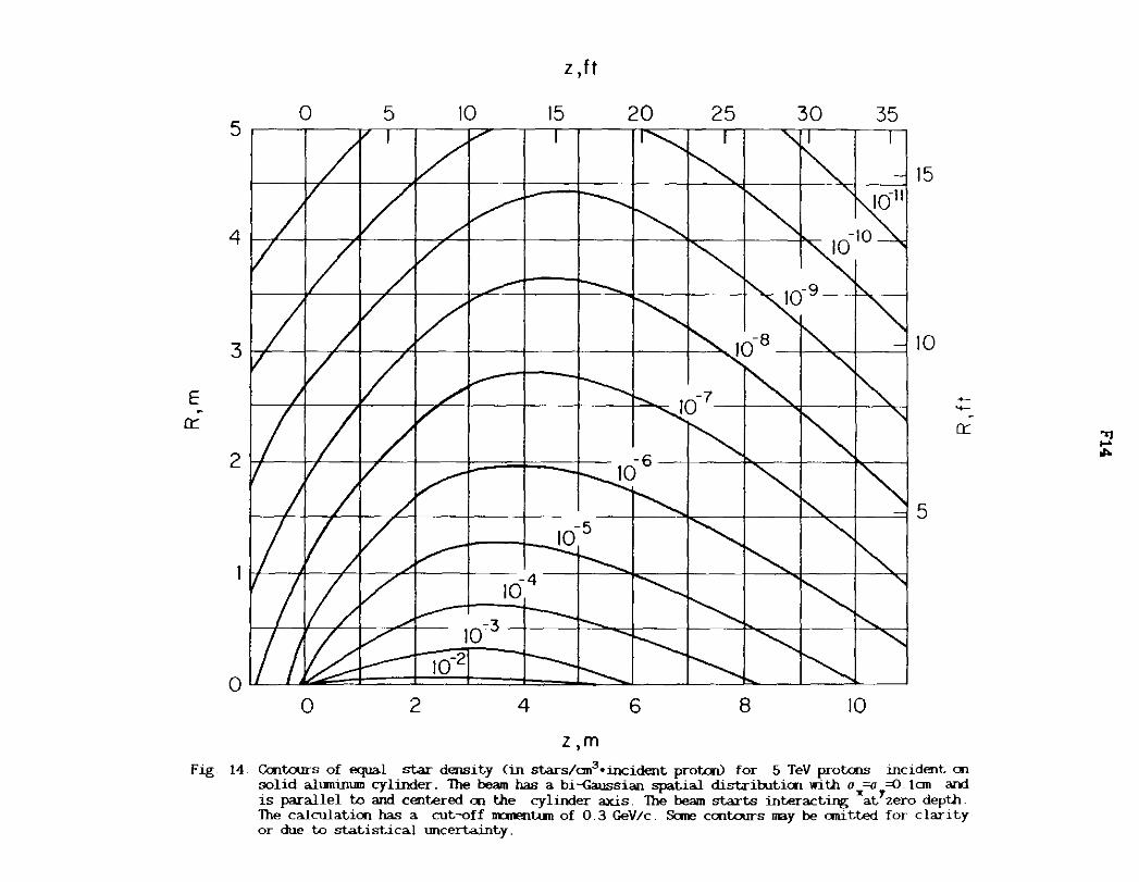
z ,m Fig. 14. Gait.ours of equal star density (in stars/an3•incident protcru for 5 TeV protons incident =
solid aluminum cylinder. The beam has a bi-Gaussian spatial distriruticn with o =o =O. lan and is parallel to and centered en the cylinder axis. The beam starts interacting "at1zero deptii. The calculatioo has a cut-off nanentun of 0.3 GeV/c. Sane cent.ours nay be C1111tted for clarity or due to statistical uncertainty.
"'l .... ,,..

z, f I
5 0 5 10 15
4 --
3
E ~
0::
2
0 0 2 4
z, m
20 25 30
10-7
6 8
35
10
15
10
5
-.._ 0::
Fig. 15. Cont.ours of eq.ia1 star density (in stars/an3 •incident proton) for 10 TeV protoos incident an solid aluminun cylinder. The beam has a bi-{iaussian spatial distr1butirn with o =o =O. lan and is parallel to and centered rn the cylinder axis. The beam starts interacting z at1 zero depth The calculation has a cut-off m:mentum of 0.3 GeV/c. Sane cant.ours may be anitted for clarity or due to statistical uncertainty_
"SI o;

E 0:::
5
4
3
2
0
0 5
0 2
z,ft
10 15
10-5
10- 4
10-3 10-2
4
z,m
20 25 30
10
10-6
6 8
35
10-10
-9
10
15
10
5
-'+-
0:::
Fig. 16. Contours of equal star density (in sta.rs/an3 •incident protcru for 20 TeV protcns incident, on solid alumimmi cylinder lhe beam has a bi-Gaussian spatial disLriruLicr1 with ox =o =-0 !cm and is parallel to and centered <Tl the cylinder axis. The beam st.alts interact,ing at,"zero depth The calculat,ion has a cut-off nanentum of 0 3 GeV/c. Sane contours nay be ani t;t,ed: at high star density for clarity and at l<M star density due to statistical uncertainty.
..., o;

~
z 0 I-0 Ct: CL
u c
E u ....._
(fl
Ct: <I: I-(fl
>-I-(fl
z w 0
Ct:
~ (fl
F17
z' ft
0 5 10 15 20 25 30 35 !I I I I I ,_
~ 10 1
~ 10 I
10° 20 TeV 10° 10 TeV
5 TeV
10-1 10-l
10-2 10-2
-1 0 2 4 6 8 10
z, m
Fig. 17. Radially integrated star density (in stars/an•incident proton) for 5, 10 and 20 TeV protons incident an 12m long solid aluminum cylinder. The calculation has a cutroff m:ment.um of 0.3 GeV/c. The prot.cns begin interacting at zero depth.

~
z 0 f-0 a::: a.. u c
E u
....... (/)
a:: <( f-(/) ->-f-C/)
z w 0
a::: <(
f-C/)
F18
RI ft
10 2 10 2
101 10 1
20 TeV 10 TeV
10° 10° 5 TeV
' 10-1 10-1
10-2 10-2
2 3 4 5
R,m
Fig. 18. I.nngit;Jdina.lly integrated star density (in stars/an•incident. proton) for 5, 10 and 20 TeV protons incident on 5.Qn radius solid a.lumimmi cylinder. The calculation has a cut-off m::mentum of 0.3 GeV/c.

z, ft
3 0 5 10 15 20 25
2 I / A /I --+
E
er
0 0 2 4 6
DEPTH z,m
8
8
6
-.._
4 O'.'
2
Fig, 19, Centaurs of eqial star density (in stars/an3 •incident protoo) for 5 TeV prolals incident on solid iron cylinder, The beam has a. bi-<:aussian spa.tia.l distributicri with a =o =-0_ 1an and is pa.ra.llel to and centered on the cylinder a.xis, 'fue beam starts interacting"at7zero deptlL TI1e ca.lcula.tion has a cut-off nanentum of 0_3 GeV/c. Sane ccritourn may be emitted for clarit,y or due to statistical tnlCertainty.
'Tl
:0

E
0:::
z , ft
0 5 10 15 20 25 3 I I I It I 17 I II I :.;;#" I I I I ...... I I I I I Q I I Kl I I 4 I I I ' Ii I I I I I 1 I
8
2 I ' 'I ' I I l ":! ' I ' I 7 T --- ..__ '-' '-6
4
2
o I I I I N? ·1 I =:........J "- I "' I'\ '\I \ I \ \I \ I o 0 2 4 6 8
DEPTH z, m
~ -0:::
Fig. 20. Centaurs of equal star densit.y (in st.u-s/an3 • incident. proton) for 10 TeV protcIJs incident. on solid ircri cylinder. The beam has a bi-{;aussian spat.ial dist.ribut.ioo with o =o ~ Ian and is parallel w and cent-ered on the cylinder axis. The beam starts int-eract.in~(at.1 zero depth The calculat.ion has a cut.-off nanentun of 0.3 GeV/c. Sane contours may be anitt-ed for claritcy or due w st,at.i8Lical tmcert.ainty.
~

z,ft
0 5 10 15 20 25 3 fl I /I t I/ I II t :;f t \I I I II I "'1 t I I,. I I I " 11 I'\ I Ii ( I Ii I I I I
2 I / A / I ,.. I ---l I " I '\. i'\. r,, r.,.,,. t~ ",
E
0:::
1
0 0 2 4 6 8
DEPTH z ,m
8
6
4
2
~
4-
0:::
Fig. 21. Cont.o.irs of equal st.ar density (in stars/cm3•incident protcn> for ~ TeV protais IDCldent oo solid iron cylinder. 1'he beam has a bi-Gaussian spatial dist.ribut1an with o ""' =(J. tan and is parallel to and centered an Ille cylinder 3X1S. lhe beam starts interactingxat!zero depth The calculation has a cut-off nnnentum of 0.3 GeV/c. Sane cc:nt.o.Irs nay be emitted for clarity or due to st..at.istica.l tm.eert.a.:int.y.
~ ~

~
z 0 I-0 0::: CL
u c
E u
....... (/)
0:::
~ (/) ~
>-I-(/)
z w 0
0::: <( I-(/)
F22
z 'ft
0 5 10 15 20 25
10 1 10-1
10° 10°
5 TeV 10-1 10-1
10-2 10-2
10-3 10-3
10- 4 10-4
10-5 10-5
10-6 ~~"'---~~~-'----~_._~_._~_._~_._~_.__._~10-6
-1 0 2 4 6 8
z, m
Fig. 22 Radially integrated star density <in stars/an•incident proton) for 5, 10 and 20 TeV protons incident on 12m long solid iron cylinder. The calculation has a cut-off nanent.um of 0.3 GeV/c. The protons begin interacting at zero depth.

z 0 I-0 0::: a... u c
E u
' en 0:::
~ en ->-I-en z w 0
0:::
~ en
F23
RI ft
2 4 6 8
10 2 10 2
10 1
10 1
20 TeV
10° 10 TeV 10° 5 TeV
10-1 10-1
10-2 10-2
10-3 10-3
10- 4 10-4
R,m
Fig. 23. Longitudinally integrated star density (in st.ars/an•illcident proton) for 5, 10 and 20 TeV protons illcident an 5. Om radius solid iron cylinder. The calculation has a cut-Qff m:mentum of 0.3 GeV/c.

E
er
z , ft
0 5 10 15 20 25 3 ti 171 I 171 ii I I I II I I II '1:L I I I K: 111 \:I Ii 'I ii I I 11 I I it
2 11 I I / I I !'... I '\. I\. \,I \
8
6
~
'+-
4 er
2
0 I I I I flK '"! I :---..,_ '-!. "- I "\ '11 \ I \ '1 \ I \ l Q
0 2 4
DEPTH z, m 6 8
Fig 24. Centaurs of equal star density (in starn/an3 •incident protal) for 5 TeV protais Incident on solid lead cylinder. The beam has a bi-<iaussian spatial distribution with o =a =O. Ian and is parallel to and centered on the cylinder axis. The beam starts interacting"at7 zero depth. The calculation has a cut-off m::mentum of 0.3 GeV/c. Sane contours may be anitted for clarity or due to statistical uncertainty.
~

E
er
0 5 10 z ' ft
15 20 25 3 II I I II I I I I 7 I I I I I ......... I Ii I -.: I I I "I I I I ' I I I I\: I Ii I I ft I I I I
21'--+---++-~+--~-1-~-+--~~___,,.------+-___ ~.,__---'l
8
6
4
2
I I I II? ·-0 I ~ =:.......,, ['... 1'. "\. I \ I\ \I \ I\ \J 0 0 4 6 8
DEPTH z , m
~
4-
er
Fig. 25. Cant.ours of eq.ial star density (in stars/an3•incident proton) for 10 TeV prot.cris incident an solid lead cylinder. The beam has a bi-Gaussian spatial distributi<Il with a =o =O. Ian and is parallel to and centered an the cylinder ax:is. The beam st.arts interactingiat7 zero depth. The calculatiai has a cut-off nanentum of 0.3 GeV/c. Sane contours may be anitted for clarit,y or due w st,atist,ical wicertainty.
~

E
0::
z,ft
0 5 10 15 20 --3 ii I I A I I WI I 111 I I ....... I I • 'l I I['( I IN I 1\:11 I I II I I 11
\.I cJ8
2 I / I ,L I """ I """' I 'l, '\.I \
0 0 2 4
DEPTH z, m 6 8
6
-..._
4 0::
2
Fig. 26. Contours of equal star density (in stars/an3•incidelt proton) for 20 TeV protals jncjdent ai
solid lead cylinder. The beam has a bi-Gaussian spatial distributiCll with u =-0 =() tan and is parallel to and centered Cll the cylinder axis. The beam starts interacting" at
1 zero depth.
The calculatiCll has a cut-off DDieltum of 0.3 GeV/c. Sane cCBltours nay be anitted for clarity or due to statistical \Illcertainty.
~

~
z 0 I-0 a:: a... u c
E u
........ (f)
a:: ~ (f) ~
>-I-(f)
z w 0
a:: <( I-(f)
z 'ft
0 5 10 15 20 25
10 I 10 1
10° 20 10°
5 TeV 10-1 10-1
10-2 10-2
10-3 10-3
10-4 10-4
10-5 10-5
10-5 _ __. _ __, _ ____.. _ __,_ _ __,_ _ __,_ _ __,_ _ ____L~.__. 1 o-6
-1 0 2 4 6 8
z ,m
Fig. '27 Radially integrated star density (in stars/an•incident proton) for 5, 10 and 20 TeV protons incident on 12m long solid lead cylinder. The calculation has a cut-off rranentum of 0.3 GeV/c. The protons begin interacting at zero depth.

z 0 I-0 a:: Cl.
u c:
E u ' Cf)
a:: <l: I-Cf) ~
>-I-Cf)
z w 0
a:: <l: I-Cf)
F28
R ,ft
2 4 6 8
10 1 10 1
20 TeV 10 ° 10 TeV 10°
5 TeV
10-1 10-1
10-2 10-2
10-3 10-3
10-4 10-4
10-5 '-'--'---'---'--'--'--'--1-L.-l-L-'--1-L.-'---l---'--'---'---'--'---'--'--'---1-J'-L--'--"-'110-5 2
R,m
Fig. 28. Langi tudina.11 y integrated star density (in stars/ an• incident proton) for 5, 10 and 20 TeV protons incident an 5. Qn radius solid lead cylinder. The calculation has a cut-off m:::mentum of 0.3 GeV/c.
E
~
>-II ~
x
3 I
2 I/
~
'
0 -2
10-4 -
10-3 )
' 10-2 I
10-1)
100,
-I
II
.
0 0
T ,
10-3
'--10-2
'--._10-1
100
101
'-L 102
103 '--
'--
' 104
2 3 4 5 6 7
z, m
Fig. 29. Cent.ours of eq.ial total staz- product.icn in (wet.) soil (in staz-s/incident. prot.cW out.side solid ircn block of dimensions 2x. 2y(=2x) and z in meter by 20 TeV prot.ans. The beam has a bi-Gaussian spat.ia.l dist.ribut.icn with o =o =(l.1an and is paz-a.llel to and centered en the axis of the block. The beam staz-t.s int.eract.wg al. zero depth. The calculat.icn has a cut.-off m:mentum of 0. 3 GeV I c.
~

0
~ 101
N
9 II >. II )( -~ u 10·2 0 ...J CD
10"3
UJ 0 (J')
10"4 I-:::> 0
10"5 (J')
ct: <l
10"6 I-(J')
10·1
10"8
Fig. 30.
5 10
z. ft
15
4
lzl, m
20 25
5 6 7
104
103
102
101
10°
10-1
10- 2
10-3
10-4
10-5
10-6
10-7
10-e
8
Sta.rs in soil <in stars/incident proton) outside infinitely wide solid ircn block as a functicn of length of the block. The block has finite length either for z<O or for z>O and is infinitely loog in the Cff>OSite direction. The calculaticn has a cut-off m:mentum of 0.3 GeV/c.

~
8 II N . >-II )(
~ u 0 _J
CD
w 0 (/)
I-::::> 0
(/)
a:: <l I-(/)
0
102
101
.. 10-3
10-4
10·5
10·6
10·7
10"8
0
t" 0
F31
x(=y),ft
5
~o .s ~
/' t-(ii/;
2
x(=y),m
10
10 4
103
102
101
10°
10-1
10-2
10-3
10-4
10" 5
10- 6
10-7
10-8
3
Fig. 31. Stars in soil (in stars/incident protcn) outside infinitely long solid iron block as a functian of length of the block. The block has finite width either for z<O or for z>O [x(=y) is the half widtilJ and is infinitely wide in the other halfspace. The cal.culatian has a cut-off nanentum of 0.3 GeV/c.

~
N
8 " >-
" >< ~
~ u 0 _J CD
1.1.J Cl Cf)
1--::::> 0
Cf)
0:: <t 1--Cf)
F32
IZI, m WET SOIL
0 5 10 15 20 25
10 4
10 3
10 2 102
101 101
10°
10·1 10- 1
10· 2 10·2
10"3 10- 3
10" 4 10- 4
10·~ 10· 5
10"6 10"6
10·7 10-7
10"8 10" 8
10 15 20 25
lzl, m CONCRETE
Fig. 32. Stars in soil (in stars/incident proton) outside infinitely wide solid concrete <bottan scale) or wet soil (top scale) block as a functicn of length of the block. The block has finite length either for z<O or for z>O an:i is infinitely long in the opposite directicn. The calculation has a cutoff m::lllE!!ltl.lm of 0.3 GeV/c.

0
~
8 II
N
>-II
"' -~
10· 1 u 0 ...J cc
10·2 LLJ Cl (/) 10-~ t-::::l 0
10"4 (/)
Ct: <{
10· 5 t-(/)
10"6
10·7
10"8
Fig. 33.
x (=yl, m WET SOIL
2 3 4 5 6 7 8 9
x {=y), m CONCRETE
Sta.rs in soil <in st.a.rs/incident prot.aV outside infinitely long solid concrete <bottan scale) or wet soil Ctop scale) block as a. functian of length of the block. The block has finite width either for z<O or for z>O (x(=y) is the hali width] and is infinitely wide in the other half-space. The ca.lcula.tian has a. cut-off m::mentum of 0. 3 GeV/c.

z ,ft
5 50 I
I I I I I I
.....
40
-- -------
17 106
L. J
I 105/
, -
I
E u
a:
I I I
104 J I I '! --
I I
I I 1~~ ~
30
20
I I 1/ /
I I I/ /
10
~ / ___ ........
0 2
z,m
10 I I I I I I
- f--_
-
--
- ----
10-2
10-1 -r-10° ii
3 4
15 I '
-
----
-
-
-- --
-
-
-
5
15
{f)
w I
10 u z
a:
5
Fig. 34. CalWIJrs of equal energy density (in GeV/an3 •incident protcn) for 5 TeV protons incident, an solid carboo cylinder. The beam has a bi-<iaussian spatial distributirn with a =a =O tan and is parallel to and centered cn the cylinder axis. Sane ccnWIJrs may be anitW7for clarity or due to >rt.atistical uncertainty.
~

50
40
30
E u
0:::
20
10
0
z, ft
5 10 15 I l T
106 /~ 1 [II /' i[/~-or--r--T---.-T'-~,-.~ /
II I 'I I I I II
I I - I - -- ' ' I ' _'
105 / . I , lt----r--~-/-1]_ -- ~- - . _ -
I I 16/ I I I -
I r-----1-/'_f_ : I/ -1---- -I - 10,'/ ~ I II / / - ~ r/f ,, / 16
2
I/ -_I ____.-- - '-- -10 1 ' ---.:
1100 - r--..: 2 3 4 5
z ,m
15
10
5
U)
w I 0 z
0:::
Fig. 35. Contours of equal energy density (in GeV/an3•incident protcrV for 10 TeV protons incident on solid carbon cylinder. The beam has a bi-Gaussian spatial distribution with a =o =D tan and is parallel to and centered on the cylinder axis Sane contours may be anitl'.e<!Y for clarity or due to statistical uncertainty.
~
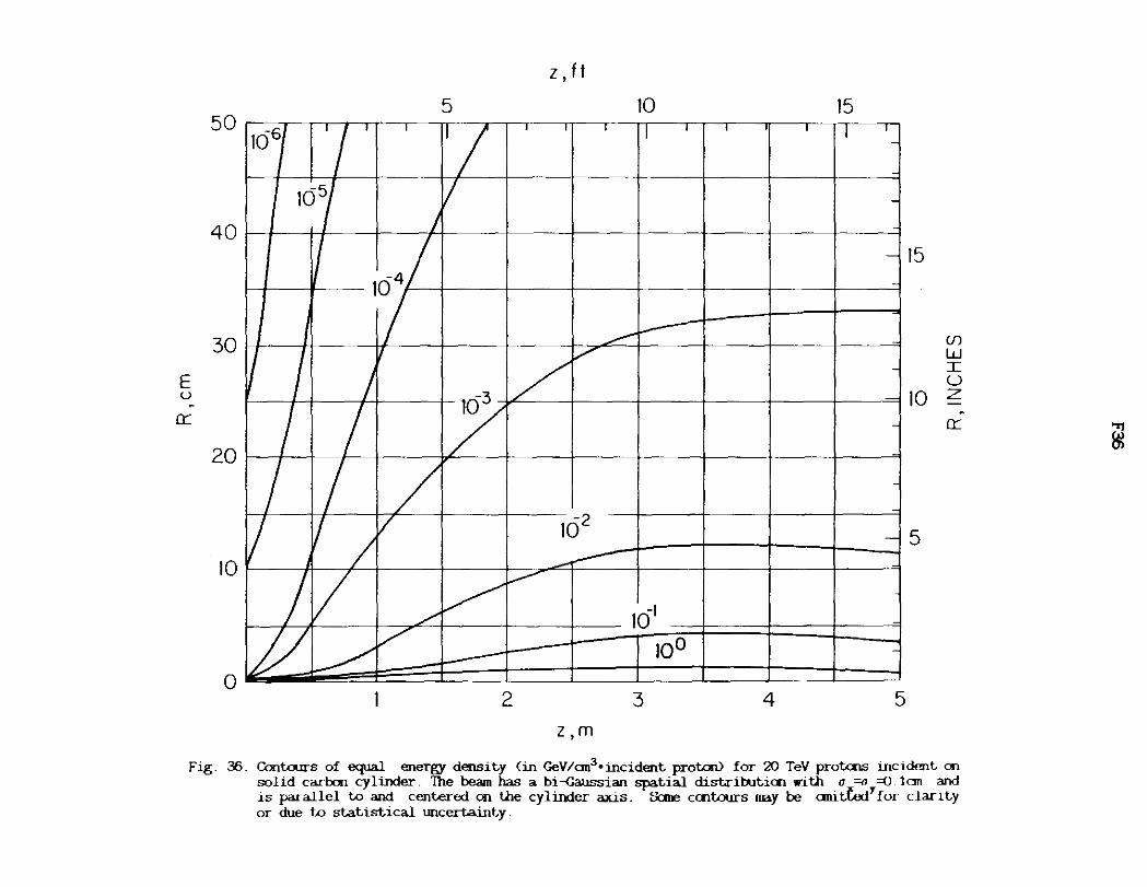
50
40
30
E u
0:::
20
10
0
z, f I
5 10 15
106/ ' ' I I fl I I ' I I I ' ' '
J(j5/ 7 I r
I I ' ~ I
1641 j -I ---11-~4--/ I /~ -I I -~ / -I I / -
7 / / 162 -
/I/ I ----~ ~ )_,-- -I// /_,,, _ 10' 100 --
2 3 4 5 z ,m
15
U)
w I u
10 z er
5
Fig. 36. Cont.ours of equal energy density (in GeV/an3•incident proton) for 20 TeV protons incident on solid carbon cylinder. The beam has a bi -Gaussian spatial dist.rib.it-ion with o =o =Q 1 an and is parallel to and cent.erect en the cylinder axis. Sane cont.ours may be anit:.Uid'ror clarity or due t:,o statist.ical uncertainty.
~

z 0 I-0 a:: 0...
u c --. E ~ > Q)
(.'.)
>-I-(f)
z w 0
>-(.'.)
a:: w z w
Z If t
10 1 10 1
20 TeV
10 TeV 5 TeV
10° 10°
10-1 10-1
0 2 3 4 5 Z Im
Fig. 37 Radially integrated energy density (in GeV/an•incident proton) for 5, 10 and 20 TeV protons incident on 5m long solid carbon cylinder.
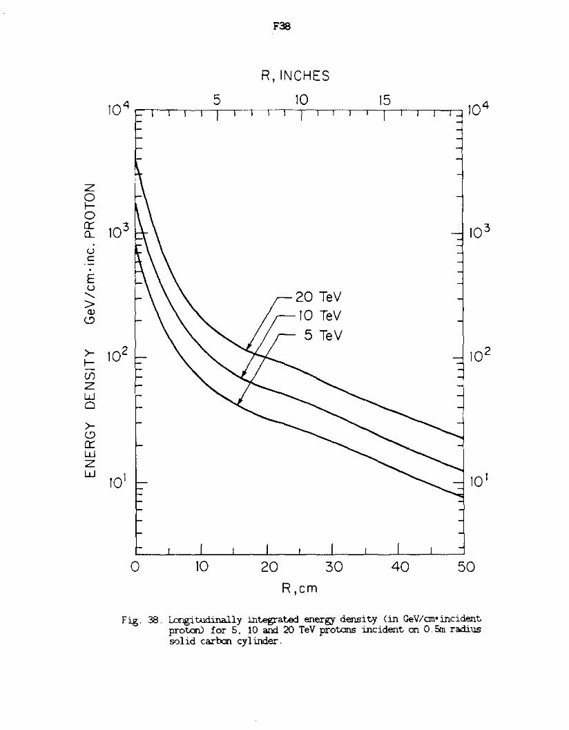
z 0 f-0 a:: CL
u c: . E u
....... > <lJ
(.'.)
>-f-if)
z w 0
>-(.'.) a:: w z w
F38
R, INCHES
4 5 10 15 10 ~~~-~~~ ---.--.---.---,--.-.--.--.---.--.--.--.,.-, 10 4
103 103
20 TeV 10 TeV
5 TeV
102 102
101 10 1
0 10 20 30 40 50
R ,cm
Fig . 38 . Langi tllii:ina.11 y integrated energy density (in Ge VI cm• incident proton) for 5, 10 and 20 TeV protons incident on O.Sm radius solid ca.rh:in cy 1 inder.

w fw 0:: u z 0 u
E u
0::
50
40
30
20
10
0
-
• 11/ I
,_ I j ...
106 I I 105/
/I/
l I/ 10~/ I
I I
7 I I/ I/ &J
/
• /
J /
I I/ -7 /~ _,_,,/
2
z,m WET SOIL
3 4 I I
I 1 I I I
- -------v ~
/
- t 8.7· 10-4
~
~
10-2 T
--~ 1e5' 10°
,; - -
5 I I
-__ L__ ·-
~ f.... '-----
-
-
-
-
~ ~
-
---- ~ ---~ 2 3 4 5
z, m CONCRETE
50
40
__J -0
30 Cf)
f-w ~
E u
20 0::
10
Fig. 39. Cent.ours of equal energy density (in GeVl<:m3 •incident protaU for 5 TeV protais incident en solid concrete/soil cylinder. The beam has a bi-{iaru;sian spatial distributien with o =o ={) !cm and is parallel to and centered en the cylinder axis. Cent.ours for concrete <left It botfu1.7axes) are integral powers of ten. Cent.ours for (.,..,t) soil <right It top axes) IWSt be scaled down by 0. 81 as sha.m for ene exanple. Sane cent.ours may be emitted for clarity or due to statistical WlcertainLy
m

z,m WET SOIL
2 3 4 5 50
50 I I I I 1/ I I I l
/ I I
-
40 40
'/ 105/
I I I -
-
w I-w 30 a::: u z 0 u
E u 20 .
a:::
_j
0
30 (})
I-w 5:
E
20 u .
a:::
104
)
I -
I I I
fB.7·10-4 -
I/ - .........
I---I/ I
I0-3 ,
-
1/1' ~
~
-
10 I I 102
-
I/ 1~"' . r--r--
-
/ v r---
10-I -t- JOO ,/
-......:
10
0 -2 3 4 5
z, m CONCRETE
Fig. 40 Contours of equal energy density (in GeV/ao3 •incident protcn) for 10 TeV protoos incident on solid concrete/soil cylinder. The beam has a bi-Gaussian spatial distrirution with o =a =0. !ao and is parallel to and centered on the cylinder a.xis. Contours for concret.e <left .t botbYaxes) are lll
tegral powers of Um. Contours for (wet) soil (right .t tq> axes) llJ.JSt be scaled dawn by 0.81 as shown for one ex:anple. Sane contours may be anitted for clarity or due to statistical lillcertarnty
~
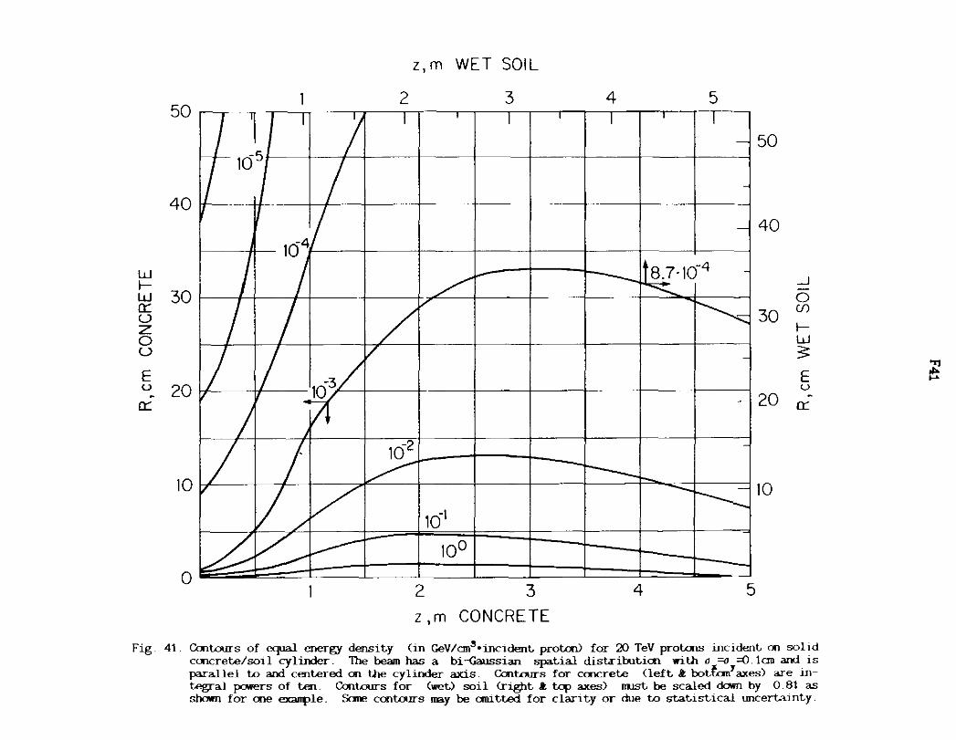
w f-
50
40
w 30 0::: u z 0 u
E u 20
0:::
10
0
I 'I I ) ~105 ~
104 I J
L L I I 103 /
/ j_ -
,
// / k ~ ~
z,m WET SOIL
2 3 4 5 I ' I ' I I I
50
-
- 40
_J
0 (f)
30 f-w
TB.7·10-4 -/
I""""'
........
I~ /~ 3: -I'
E u
20 . 0::: -
-10 2
~ 10 --r--
10-1
-10°
2 3 4 5
z ,m CONCRETE
Fig. 41. Contours of equal energy densit.y (in GeV/an3•inc1dent. proton) for 20 TeV protcns incident, oo solJd ccncret.e/soil cylinder. The beam has a bi-<:iaussian spat.ial dist.ribuLioo with o =o =O. lan and is parallel to and cent.ered cn the cylinder axis. Contours for ccncret.e <left. .I: bot.fail axes) are integral powers of t.en. Contours for (wet.) soil <rigtit. .I: t.ap axes) nust. be scaled daovn by 0 81 as shown for cne ex311ple. Sane contours may be aru.t.t.ed for clant.y or due to st.at.ist.ical uncert.aint.y.
'"rj ,,,. ,_.

F42
z, m WET SOIL
102 2 3 4 5
z z 0 0 f-f- 0 0 0::: 0::: a.. 0....
u 101 10 1 u c: c:
E E u u >: >: <lJ aJ
(.'.) (.'.)
w 10 TeV __J -f-
10° 10° 0 w 5 TeV (/) 0::: u f-z w 0 3:: u >-" >-f- f-
(/) (/)
z z w 101 101 w 0 0
>- >-<..9 (.'.) 0::: 0:::
w w z z w w
10-2 10-2
0 2 3 4 5
z,m CONCRETE
Fig. 42. Radial 1 y int.egra ted energy densit.y (in GeV/an•incident. proton) for 5, 10 and 20 TeV prot.ons incident. on a 5m long solid con-cret.e <left. & bot.tan axes) or soil Cright. & top axes) cylinder.

z 0 f-0 et: 0...
u c ·-. E u >: CV
(.'.)
w f-w et: u z 0 u ~ f-en z w 0
>-(.'.)
et: w z w
F43
R,cm WET SOIL
10 4 10 20 30 40 50
103 103
20 TeV 10 TeV
102 102
10 1 10 1
0 10 20 30 40 50
R,cm CONCRETE
Fig. 43. Wngiw.d.i.na.lly integrated energy density (in GeV/an•incident proton) for 5. 10 and 20 TeV protons incident on 0 5m radius solid concrete <left & bottcm axes) or soil <right & top axes) cylinder.
z 0 f-0 et: 0...
u c . E ~ > CV
<..?
_J
0 en f-w ;: r: f-(f)
z w 0
>-<..? et: w z w

50
40
30
E u
0:::
20
10
0
z ,ft
5 10 15
' 7 ' /
II I I' I
~+--Jt_ __ _J I ' I I . ' 1 ' l
166
- -. I I /,,,.. --._ _ I 105 /v ~ -~ -
I 104/ "-.._-/ I I I
I 10-3
i/f - -I I ~ -----_, •
I I '
162 ~ I ---r--r:'..__-L-I// __,,. -c-v ~ 10-1 ir-100 -
J - r-- --= 2 3 4 5
z,m
15
en w
10 0 z 0:::
5
Fig. 44. Contours of equal energy density <in GeV/an3 •incident protcrV for 5 TeV protc:Es incident en solid almrinun cylinder. The beam has a bi-Gaussian spatial distributicn with o =o =O. !an and is parallel to and centered en the cylinder axis. Sane cent.ours may be anittedxfo1 clarit,y or due to st,atistical tmcert,ainty.
t
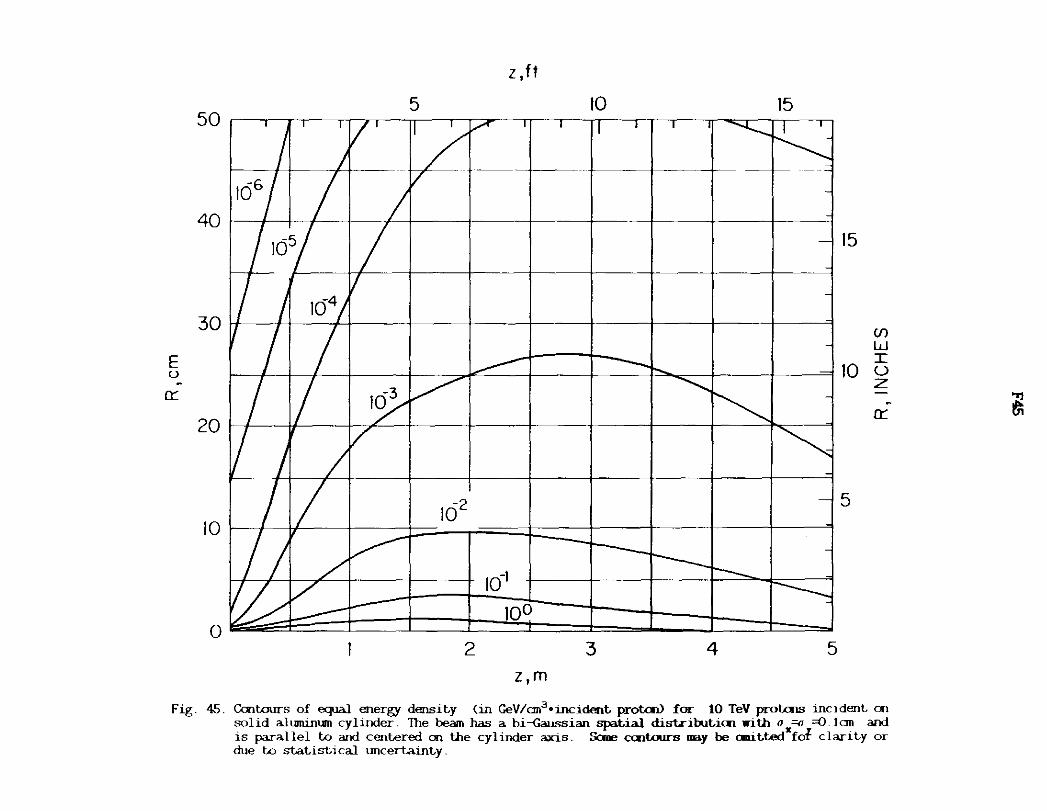
50
40
30
E u
0::
20
10
0
z I ft
5 10 15 I I l
I I/ I TI I "
-· I j . / ' I ' ' 10
5/ I I/ ···- "-.I 'l
/ ,a,/ / -L---:-11 I ,) ·
I/ 1 ICJ•, -
I I -I II ,~I/" -· -
I/ I/ ' I / ~ .
. /I/ ~ I
102
I )__,... -- -V/'.)/ ~ -~ 10 ---... -
-._,, -10~ - ----- . ......_
2 3 4 5 z,m
15
Cf)
w I
10 u z .
0::
5
Fig. 45. Contours of equal energy density (in GeV/an3 •1JlCident protal) for 10 TeV prol:.als incident on solid alumimnn cylinder. The beam has a bi-Gaussian spatial dist.icibuticn with o =-0 =D Ian and is pa.rallel to and centered oo the cylinder axis. Sane cent.ours DBY be cmittedxfof clarity or due to statist,i cal tmcertainty.
~

5 50
- --
40
30
E u
a::
20
162
10
10-1
10°
0 2
z. ft
10
- - -
3 4
z,m
15
- -
5
15
(/) w
10 Q z a::
5
Fig. 46. Cult.ours of equal energy densit.y (in GeV/an3•incident. prolal) for 20 TeV prolals incident. cu solid aluninun cylinder. The beam has a bi--<iaussian spatial dist.ribut.icn with o =<J =O. lan and is parallel to and cent.ered on the cylinder axis. Sane crnt.ours may be cnitted~tJ clarity or due to statistical uncertainty.
~

z ~ 0 a:: a... u i:: ·-. E u ....... > aJ
(.'.)
>-f-CJ')
z w 0
>-(.'.) a:: w z w
F47
z ,ft
5 10 15 10 2 c:-,--,---.---.--r--i~.-.-.--~---.--.~.-.---,.---,....,
101 101
10 TeV 10° 5 TeV 10°
10-1 10-1
0 2 3 4 5 z, m
Fig. 47. Radially integrated energy density (in GeV/an•incident proton) for 5, 10 and 20 TeV protons incident on 5m long solid aluminum cylinder.

z 0 I-0 0::: 0... . u c:
E u
::;; Q)
(.'.)
>-I-(f)
z w 0
>-(9
0::: w z w
F4B
R, INCHES
5 10 15 104 ~~~r ~1 ----,-[ ~T~-~.--~·,--.--.-~-.---,-----.-----,-~~ 10 4
103 103
20 TeV 10 TeV
102 102
101 10 1
0 10 20 30 40 50
R,cm
Fig. 48. Longitudinally integrated energy density <in GeV/an•incident proton) for 5, 10 and 20 TeV protons incident on O.Sm radius solid aluminum cylinder.

z, f I
50 5 10 15
40 I I I I I I I I I '\. I I \. I ~07
_
15
5
10 I/ I I .-- I ---
2 3 4
z ,m
Fig. 49 Contours of equal energy densit.y (in GeV/cm3•incident. proton> for 5 TeV prot.cru; incident. an solid iron cylinder. The beam has a bi--Qwssian spat.ial dist.ribut.ion with o =o =Q. lcm and is parallel t.o and cent.ered an the cylinder axis. Scme cont<:Jurs may be anittedxfot clarity or due t.o st.at.ist.ical lDlcert.aint.y.

z 'ft
50 I I I II I i 17 I ,5 10 15 1 I I I K: I 1 1 f ""- I I I\ I I I I
40 I I 11 I .- I ._ I I I \: I I \: 15
30 -- - - -Cf)
w E . I / A I.- I~ I I 1\, I ~ I \zl 10 ~ 0::
. - - - - 0::
20
5 10 11 I I ,,..c I F"'"" I I 'l I '\.I I \: i
o~ I 1001 I d:: I J'=........... I >.I I'\.. I 2 3 5 4
z,m
Fig. 50. Contours of equal energy density (in GeV/an3 •incident prol:al) for 10 TeV prate.is incident = solid ircrJ cylinder. The beam has a bi-Gaussian spatial distributicn with o =o =O.lan and is parallel to and centered crJ the cylinder axis. &me centaurs may be anittedxfot clarit,y or due to statistical uncertainty.
"rl
~

z ,ft
50 5 10 15
5 JO r ! A I I I ""'- I I "x I I \. I 9
10-1
10° o~I I I f::::L I ~ I">. I '\l
2 3 4 5 z ,m
Fig 51 Contours of equal energy density (in GeV/an3 •incident. protaV for 20 TeV prot.ais incident. on solid iron cylinder. The beam has a bi--{;aussian spatial distribution with a =u =0. lan and is parallel to and centered on the cylinder axis. Sane contours may be anit.t.edxfo1 clant.y or due to statistical tmcertaint.y

z 0 t-0 Ct: 0... . u c: . E u '-> <V
<..'.)
>-t-U) z w 0
>-<..'.) et:: w z w
F52
z 'ft
0 5 10 15
102 20 TeV 10 2
10 TeV
5 TeV
101 10 1
10° 10°
10-1 10-1
10-2 10-2
0 2 3 4 5 z, m
Fig. 52 Radially integrated energy density Cin GeV/an•incident proton) for 5. 10 and 20 TeV protons incident on 5m lang solid iron cylinder.

z 0 f-0 0::: 0...
u c ·-E u ......_
> <ll
(.'.)
>-f-(()
z w 0
>-(.'.) 0::: w z w
0 5
103
102
10 1
10°
F53
R, INCHES
10
20 TeV
10 TeV
15
103
10 2
10 1
10°
0 10 20 30 40 50 R,cm
Fig 53. Longillidmally integrated energy density (in GeV/an•incident proton) for 5, 10 and 20 TeV protons incident an O.Em radius solid iron cylinder.

z t ft
5 10 50 15
401----+--4----.1---1-----+---+-~---+,._____~l---~+---+-----T---+-~-I
15
30
5
10 >+----+---+-----+---
0~ I 10-1Jc10° I ~ 1'J '\J [\ J
2 3 4 5 z ,m
Fig. 54. Contours of equal energy density (in GeV/an3 •incident proton) for 5 TeV protons incident on solid lead cylinder. Th" beam has a bi -<;aussian spatial distribution with o =o =O I an and is parallel to and centered on the cylinder axis. Sane contours may be anittedifof clarity or due to statistical uncertainty.
~

z , f I
50 5 10 15
40r--r--~~---r-~----r-~---r-~--r~---r--~-r---y--;---~-r-T--1
166 15
30 E I/ JI I I I ~10-l ~I + ~10 ~ u . 0:
-
20. . , ' - ·- " ' ' ' ' 0:
5
I 0 r / I .... ......--r----- ..J
~ 161
0 100 t:±:::-:1 ~"'l I ~I "S 2 3 4 5
z,m
Fig. 55. Contours of equal energy density (in GeV/an3•incident protcri> for 10 TeV protais incident on solid lead cylinder. The beam has a bi-Gaussian spatial distributioo with a =o =D Ian and is parallel to and centered oo the cylinder axis. Sane cootours may be anittedxfol clarity or due to statistical \IllCertainty.
m

z ,ft
5 JO 50 J5
40 I I/ I ::::::-1 ...._ I I I '\ I I'\ "'I \l 15
' ' ' I 'O. I (/)
w
20
5 JO 'ti I j,./ I I ',I I Y.-.. I "" I "1
JOO
0 ~ I I I C::- I c=::-....L- 1'-.-.. I ">. I 2 3 4 5
z ,m
Fig. 56. Ccrttours of equal energy density (in GeV/an3 •incident prol:aJ) for 20 TeV protcns incident oo solid lead cylinder. The beam has a bi-Caussian spatial distribution with u""' =().1an and is parallel to and centered en the cylinder axis. &me centaurs may be rnutt.ect"to1 clarity or due to statistical tmcertainty.
~

z 0 I-0 0:: Q_
u c: ·-. E u '-> <lJ
(..'.)
>-I-(f)
z w 0
>-(..'.) 0:: w z w
FS7
z' ft
0 5 10 15
102 20 TeV
10 2
10 TeV
10 1 10 1
10° 10°
10-1 1CJ1
102 10-2
103 10-3
0 2 3 4 5 z,m
Fig. 57. Radially lllt,egrated energy density (in GeV/an•incident prot.:m) for 5, 10 and 20 TeV protons incident an 5m long solid lead cylinder

z 0 t-0 0:: a.. u c
E u 3;;
CJ) (.9
>-t-Cf)
z w 0
>-(.9 0:: w z w
0 5
10 3
102
101
10°
0 10
F58
R, INCHES
10
20 TeV 10 TeV
20 30
R,cm
15
104
10 3
10 2
10 1
10°
40 50
Fig. 58. LDngiUJdina.lly integrated energy density (in GeV/an•incident proton) for 5, 10 and 20 TeV protons incident an O.Sm radius solid lead cylinder.

z,ft WET SOIL
0 50 100 150 200
7 1'1' I I ' 'I ' \l ' I I I • r 4il>: 41: 41: ~
20 6 1' I' I I " '\l ' "I " I' I I i y • .. 4c 1 < ....
5
_J 15 _J
0 0 (f) 4 (f)
f- f-w w 3: 10 3: 3 E -..__ ~
a:: a::
2 r I II I 10·- I"'- ' I'\.. l"'---.._ I ~ I I
5 I I If I """"'- '
,,. .... , ..... '""" ' ~. ' ' TUNNEL WALL
0 10 20 30 40 50 60 70 z,m WET SOIL
Fig. 59. Contours of eqJal dose equivalent <in ren/interacting protaU in soil a.round tunnel when 5 TeV protons are lost on the lllSide (with respect to the center of the ring) of the ~ipe of a continuous dipole (see fig. 73) . The protons interact at zero depth Sare contours may be emitted for clarity or due to statistical llllcertainty.
'>l
!8

_J -0 (/)
I-w ~
E 0:::
TUNNEL WALL
0 50
z,ft WET SOIL
100 150 200
' I ' I ' ' I ' .... I 20 7 If 1 -. " I/ r ' ~ 1 ~ ~ 10-
61/l A 't--~ I I \\ I\ \ 'k 'i-10-ttl ij 20
5 15
4
3 10
2 I / Ii "- I I /I"- ' 1 '- I "--.I_ I I
5 .. . . . - - ... - - -
0 10 20 30 40 50 60 70
z,m WET SOIL
_J
0 (/)
I-w ~ -'+--
0:::
Fig 00 Contours of equal dose equivalent (in rem/int.eracting protcn) in soil around runnel when 20 TeV protDns are lost. on the inside (with respect t.o the cent.er of the ring) of the be""f'lpe of a continuous dipole (see fig. 73). The protDns int.eract at zero depth. Sane contours may be anitt.ed for clarity or due t.o statistical uncertainty.
~

~
E (,)
• c: 0 -0 .... Q.
-c:
' (/)
a:: <.( I-(/)
F61
z,ft WETSOIL
IOI 0 50 100 150 200
10·1
~
10-2 ,>. '°t-
S' 10-3 ~t-
0 10 20 30 40 50 60 70
z, m WET SOIL
Fig. 61. Radially integrated star density (in sta.rs/cm•intera.cting proton) in soil shield a.round a 1. 2m radius runnel far 5 and 20 TeV protcrls interacting en the inside (with respect to the ring) of the beanpipe of a. continuous dipole inside the tunnel. The protcrls interact at zero depth. The calcula.tian has a cut-off nr:mentum of 0.3 GeV/c.
101
10·1
10·2
10·3

z ,ft WET SOIL
0 50 100 150 200
7t-+1__,__~------;~~--t~--...--t---~~~-"c----"lt--~-4~~--f~
6 1' I I I I I ~ I' 'I ' TIJ:? ....... '' '\ '" '" I I I 20
"" <
5 __J 15
__J
0 0 (/) 4 (/)
I- I-w 3 w
3 E 3 JO --~ 0:: 0::
2 1/1/ / I~ 'l "-... I...........__ I ~ --+.-....._ l'-1
5 TUNl\EL
WALL
0 10 20 30 40 50 60 70 z,m WET SOIL
Fig. 62. Cctlt.oJrs of equal dose eq.Ii valent (in rem/interacting protoo> in soil arwnd tunnel when 5 TeV protcrul are lost in the middle of the beaq>ipe of a ccnt.inuous dipole (see fig. 73}. The protcrul interact at zero depth. &mo centaurs may be anitt.ed for clarity or due to statistical tmcertainty.
~

z,ft WET SOIL
0 50 100 150 200
""" I I 20
15 _J
0 Cf)
I-w 3: 10
E ~
a::: 2
5 - -TUNNEL
WALL
0 10 20 30 40 50 60 70
z ,m WET SOIL
Fig. 6.3. Ccritoors of eq.ia.I. dose equivalent. (in rem/int.eract.:ing protaV in soil around tunnel when 20 TeV protals are lost. in tile mid:lle of tile beaapipe of a ccnt.inuous dipole (see fig. 73) . The protais interact. at. zero depth. &me ccntoors ma.y be ani t.t.ed for clari t.y or due t.o statistical tmCertaint.y.
_J
0 Cf)
I-w 3: ~ --. a:::

F64
z,ft WET SOIL
0 50 100 150 200
10 1
0 10 20 30 40 50 60 70
z,m WET SOIL
Fig. 64. Radially integrated star density (in stars/an•interacting proton) in soil shield a.round a. 1. 2m radius tunnel for 5 and 20 TeV protans interacting in the middle of the ~ipe of a ccntinuous dipole inside the tunnel. The protons interact at zero depth. The calculation ~ a cut-off nr:mentum of 0. 3 GeV/c.
10 1

z ,ft WET SOIL
0 50 100 150 200
71/'t/ / 1' .. '•I'\. 'k '\. 1'- I I 11
6 I I I' I f"' ' I ' I' ' I ' .... ~ Y< < ~ < < < K 20
5
_J 15 _J
0 0 (f) 4 (f)
I- I-w 3: w
3: 3 10
E +-~ -a::: a:::
2 r I II ~ l(Y'v ..........._ I -............. I ............_ I ..........._ ,.............._ r---...... ~I 5 . . . . - ·- - - ·- . - -· TUNNEL
WALL
0 10 20 30 40 50 60 70
z,m WET SOIL
Fig. 65. Cant.ours of equal dose eqiivalent (in rem/interacting protaV in soil ai-ound tunnel when 5 TeV prot.cl1s ai-e lost. en the outside (witli respect to the center of the ring) of the beanpipe of a continUCAJS dipole (see fig. 73). 1he prot:.ccs interact at zero deptli. &mie centaurs may be Glllitt.ed for clai-ity or due to statistical tmcert.ainty.
8l

0
_J
~ 4 I-w 3
~ -1/Y ~
50
z ,ft WET SOIL
100 150
-"~I ~
200
20
15 _J
0 Cl)
I-w
I~ 10
3
Ii ;
TU~~cc w4' v c ·~"*- =r::--- i =:::+ i ---1 i i 5
0 10 20 30 40 50 60 70
z ,m WET SOIL
Fig. 66. Centaurs of equal dose eq.ri va.lent (in rem/interacting protcn) in soil around tunnel when 20 TeV protcns are lost. en the out.side (with respect t.o the center of the ring) of the beanpipe of a ccnt.inuous dipole (see fig. 73). The protcns interact at. zero depth. Sane cent.ours nay be cmit.t.ed for clarity or due t.o statistical WlCertainty.
Bl

~
E (.) . z 0 I-0 a:: a.. -c ~
........ (/)
a:: <( I-(/)
FOi
z, ft WET SOIL
0 50 100 150 200 I crTTTl,,--rrr-rn..,.,....rrrTTTTTl--rrrrrTn-,-,TTTTTlrrr-rrTTT-i:::JlQ
10·1 10-1
10-2 10-2
20 TeV 10-3
10 TeV 10-3
5 TeV
10-4 10-4
0 10 20 30 40 50 60 70
z,m WET SOIL
Fig 67. Radially integrat.ed star density (in st.a.rs/an•interacting proton) m soil shield around a 1 . 2rn radius tunnel for 5 and 20 TeV protons interacting on the outside (with respect to the ring) of the beanpipe of a continuous dip:>le inside the tunnel. The protons interact at zero depth. The calculation has a cut-off m::rnentum of 0.3 GeV/c

_J
0 (f)
f-w ~
-E u
z 0 f-0 0:: 0.... -c
'-(f)
0::
~ (f)
F68
R-R tunnel, m, DRY SOIL
2 3 4 5 6 7
101 10
1
10° 20 TeV 10°
5 TeV
10-1 10-1
10- 2 10-2
1 o-3 10-3
2 3 4 5 6
R-Rtunnel m, WET SOIL I
Fig 68 Longitudinally integrated star density Cin sta.rs/cm•interacting proton) in soil shield around a 1. 2m radius tunnel for 5 and 20 TeV protons int.eracting on the outside (with respect to the ring) of the bea11¥Jipe of a continuous dipole inside the tunnel . For wet soil use left & bottan axes and for dry soil right & top axes. The calculation ha.s a cut-off m:mentum of 0.3 GeV/c.
_J
0 (f)
>-0:: 0 -E u
z 0 f-0 0:: 0.... -c -'-(f)
0:: <t f-(f)

_J
0 (/)
tw 3
z ,ft WET SOIL
0 100 150 200 50 -7~·// I --F===:r-ll~~~~-1 / - - I --
61/ r--- -- ... I/ -1-- --- -~
51/, I --r--- ~ ._ 
_J
0 U)
1-w 3
E 0::
TUNNEL WALL
z , ft WET SOIL
0 50 100 150 200 I I 7 I
I/ ------ , -6 ';I --r--.. -110-_'7-+-_u
/ --....... --- in-16
5'' / ~ ~ I/ - 10-" ===-1--t--lJ 4 IF ~14 -
3// ----~ '/ ---1'~=t----===t===f==~==1J
2 10-11
'/ / 10 10 .
l rrr===r=~==*=o-0 10 20 30 40 50 60 70
z, m WET SOIL
20
_J
15 ~ 1-w 3 E
10 0::
5
Fig. 70. Caltours of equal dose e<J1i valent (in rem/interacting protcn) in soil around tunnel when 20 TeV prot.cus are lost en the side of a bare beanpipe . 'Ille prot.cus interact. at. zero depth. Sane centaurs may be anitted for clarity or due to statistical Wlcertainty.
~

10° z 0 f-0 a:: 0.. u c
E u
' Cf) 10· 1 a:: ~ Cf)
_J
0 Cf)
f-w ~
>-f-Cf) 10-2 z w 0
a:: <I: f-Cf)
F71
z,m DRY SOIL
5TeV
IOTeV
20 TeV
0 10 20 30 40 50 60 70
z ,m WET SOIL
Fig. 71. Radially integrated star density (in stars/an•interacting proton) in soil shield a.round a. 1 . 2m radius tunnel far 5 and 20 TeV protons interacting en the side of a. bare beaqiipe inside the tunnel. The protons interact a.t zero depth. The calcula.tian has a. cut-off rranentum of 0.3 GeV/c.
z 0 f-0 a:: 0.. u .~
10-1 5 ' Cf) a:: <I: f-Cf)
_J
0 Cf)
>-~
10·2 i'.= (/)
z w 0
a:: <I: f-Cf)

z 0 I-0 a:: CL <.> .E E <.>
' (/') a:: <I: I-(/')
_J
0 (/')
I-w 3: ->-I-(/')
z w 0 a:: <I: I-([)
F72
R- Rtunnel, m DRY SOIL
2 3 4 5 6 7
101 101
10° 10°
20 TeV 5 TeV
10-1 10- 1
10-2 162
10-3 163
2 3 4 5 6
R-Rtunnel ,m WET SOIL
Fig. 72. Loogitudinally integrated sta.r density (in sta.rs/cn•interacting protal) in soil shield around a 1. 2m radius tunnel far 5 an:! 20 TeV protons interacting an the side o:f a bare ~ipe inside the tunnel. Far wet soil use le:ft i; bottan axes an:! for dry soil right i; top axes. The calculation has a cut-off oanentml of 0.3 GeV/c.
z ~ 0 a:: CL
<.> c
E <.>
' (/')
a:: ~ (/')
_J
0 (/')
>-a:: 0
>-I-(/')
z w 0
a:: <I: I-(/')

y /::::::C-~""'- - ~::::- --
~:>:·_ l -- J <-:-. /~VP ( __ ) -- (_)
c::J Fe
- Cu c=J Voe
0 0 9.5251----i-1
-i/-, IHI I I
\ CJ CJ / /1 \Ill 574 ~ 22-226-08-2
~2- 226 -06-2 ~ -) --(__ f
::..~'-'- ::-c; ___ _
(J:I l /•
~ -~ 7- 22-226-07-2 t--~f--+-~~~~~~~~~X
_)---------<;// -----
2000
Fig. 73. Cross secticn of C5 mgnet: engineering drawing (left.). detail of coils <middle) and remesentaticn in program ~t.) .
13 8\lcm

z i:2 0 0: a.. O' c -u 0 ~
<L> -.£:
E u ' (/) 0: <I f-(/)
F74
20 TeV
10-3 10 TeV 16
3 5 TeV
164
164
165
165
0 10 20 30 40 50
z, m
Fig. 74. Radially integrated sta..r density (in sta..rs/cm•interacting protaV in the a.ix of 1. 2m radius tunnel far 5, 10 and 20 TeV protcris interacting in the middle of the ~ipe of a cc:ntinuous dipole in the tunnel. The protcris interact at zero depth. The calcula.tic:n has a cut-off manentum of 0.3 GeV/c.

z ~ 0
8: OI
.S: 0 c .... Q) -s: E ~ Cf)
a:: <l: I-Cf)
F75
10_2 ~-~-_2_0_0_~ __ 4_o~o ____ 6~o_o ____ s_o_o_~
10_2
10-3
10-4
0
20 TeV 10 TeV
5 TeV
200 400 600 800
z, km
Fig. 75. Radially integrated star density <in sta.rs/cn•interacting proton) in the air of 1 . 2m radius tunnel for 5, 10 and 20 TeV protais interacting an the side of a bare bealq)ipe in the tunnel. The protals interact at zero depth. The ca.l.culatian has a cut-off nanentum of 0.3 GeV/c.
10-3
10-4

_J
0 (/)
04
I- 0.3 w s E ;,02
bo II
x 0
b 0 l
0 a
5 10
7 47X XXXb
SCALE / 9XXXX SCALE xxxx...---~
9X XXXX XXXXXX3
zxxxxxxx/<z>= 22.Sm xxxxxxxx xxxxxxxx a-= l 61 m
OXXXXXXXX7 xxxxxxxxxx
1XXXXXXXXXX3 lXXXXXXXXXXXX xxxxxxxxxxxxx
5XXXXXXXXXXXXX2 axxxxxxxxxxxxxxx
17XXXXXXXXXXxxxxxx 27XXXXXXXXXXXXXXXXXX9
ooooooaoo1031233bbb8XXX¥XXXXXXXXXXXXXXXX~bl00
15 20 25
z ,m WET SOIL
Fig. 76. Distriblt.ic:n in z of a pencil beam of 0.01 TeV 111JCES st£Hl0d in soil <histogram, right scale, in m- 1). Projected rms spread of beam as a functic:n of penetratic:n (curve, left scale. in m).
4
3
_J
0 (/)
1-w s ~
E :::L u c
' 2 :::L 0 w Q_
10-1 ~ tn
~

08
_J
0 if) 0.6 I-w s E
04 >.
bo II
x
bo 02
0 00 0
0 10 20 30
xxxxx xxxxx XXXXXl
5XXXXXX 7XXXXXXX xxxxxxxx xxxxxxxx xxxxxxxx
QXXXXXXXX SCALE XXXXXXXXX<-"<..:<e!...:c!='=-~
xxxxxxxxxq xxxxxxxxxx
7XXXXXXXXxx~<Z) = 63.0rn xxxxxxxxxxx a= 5.62m
bXXXXXXXXXXX XXXXXXXXXXXX9 xxxxxxxxxxxxx xxxxxxxxxxxxx xxxxxxxxxxxxx
7XXXXXXXXXXXXX2 xxxxxxxxxxxxxxx
37XXXXXXXXXXXXXXX xxxxxxxxxxxxxxxxx xxxxxxxxxxxxxxxxx
5XXXXXXXXXXXXXXXXXZ 5XXXXXXXXXXXXXXXXXXX xxxxxxxxxxxxxxxxxxxx
ZXXXXXXXXXXXXXXXXXXXX5 79XXXXXXXXXXXXXXXXXXXXXX
5XXXXXXXXXXXXXXXXXXXXXXXX 5bXXXXXXXXXXXXXXXXXXXXXXXXX4
2 47XXXXXXXXXXXXXXXXXXXXXXXXXXXXX5 J47957X9xxxtxxxxxxxxxxxx~xxxxxxxxxxxixxxx11
10-l
9
8
7
6
5
4
3
2
10-2
40 50 60 70 80
z,m WET SOIL Fig. T1. Dist.ributicn in z of a pencil beam of 0. 03 TeV oucns stowed in soil Orist.ogram, ri,11Pt scale.
in m- 1). Projected rms spread of beam as a f\lllCticn of penetraticn (curve, left scale, in m).
_J
0 if)
I-w s ~
E
::L u
.S::: ~
'-::L ~ 0 w o_ o_ 0 I-if)
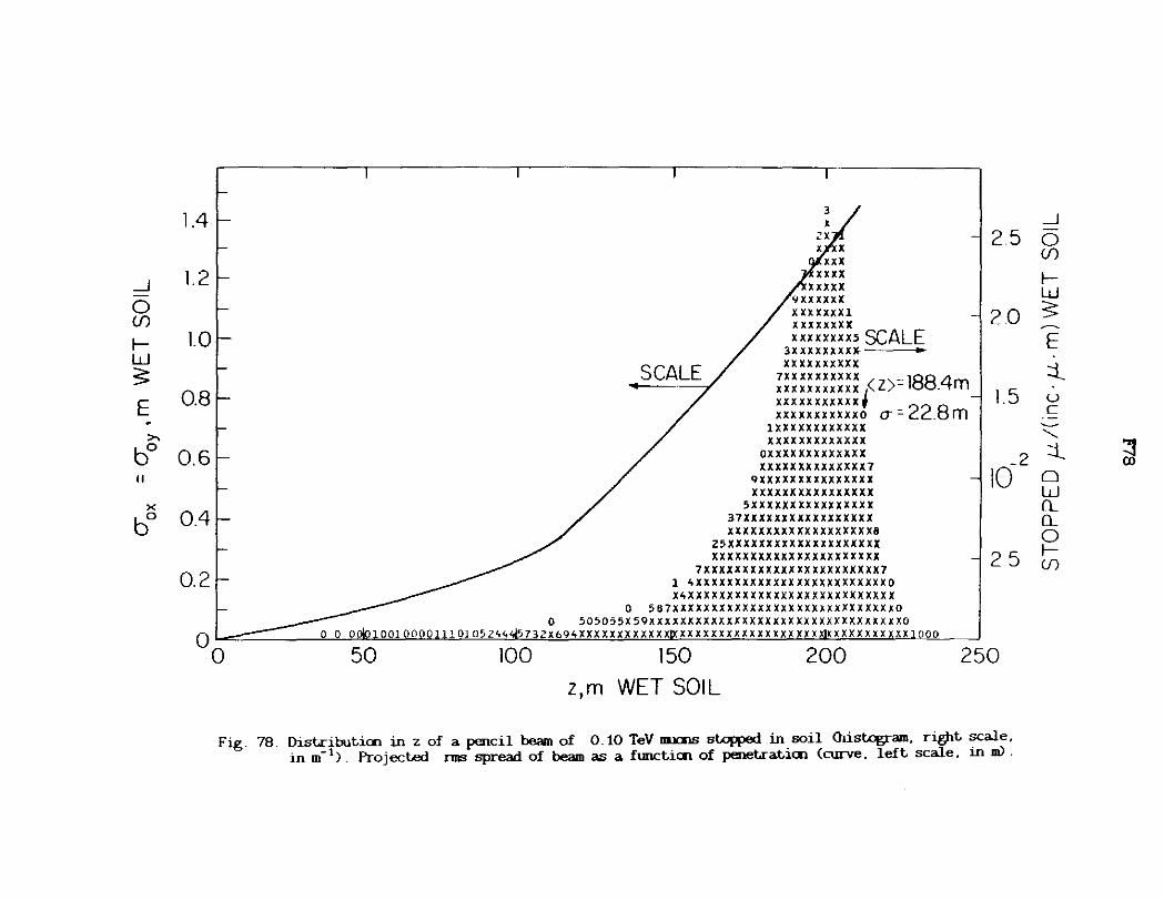
_J
0 ({)
f-w ~
E . ,,._
bo II
>< bo
1.4
1.2
LO
0.8
0.6
0.4
0.2
3
~~ xx xx
xxxxx '9xxxxxx XXXXXXXl xxxxxxxx XXXXXXXX5 SCALE
3XXXXXXXXX----XXXXXXXXXX
7XX XXXXXXXX -188 4 xxxxxxxxxxx /Z)- . m xxxxxxxxxxxr xxxxxxxxxxxo <Y = 22.8 m
lXXXXXXXXXXXX xxxxxxxxxxxxx
oxxxxxxxxxxxxx XXXXXXXXXXXXXX7
qxxxxxxxxxxxxxxx xxxxxxxxxxxxxxxx
5XXXXXXXXXXXXXXXX 37XXXXXXXXXXXXXXXXX XXXXXXXXXXXXXXXXXXX8
25XXXXXXXXXXXXXXXXXXXX xxxxxxxxxxxxxxxxxxxxxx
7XXXXXXXXXXXXXXXXXXXXXXX7
2.5
20
l.5
_2 10
25
o~ 50
l 4XXXXXXXXXXXXXXXXXXXXXXXXXO X4XXXXXXXXXXXXXXXXXXXXXXXXXXX
0 5B7XXXXXXXXXXXXXXXXXXXXXXXXXXXXXO o 5D5055X59xxxxxxxxxxxxxxxxxxxxxxxxxxxxxxxxxo
001QQQQll10105244'tfJ732Xb94XXXXXXXXXXXX~XXXXXXX~~XXXXX~X!l&XXXXXXXXXXX1000
100 150
z,m WET SOIL
200 250 0
Fig. 78. Distributicn in z of a pencil beam of 0. 10 TeV llllilS stopped in soil <histogram, right scale, in m- 1). Projected nns spread of beam as a fllllCticn of penetraticn (curve. left scale. in m).
_J
0 ({)
f-w s ~
E ::i._ u c ~
"-::i._ ~
0 w Q_ Q_
0 f-({)
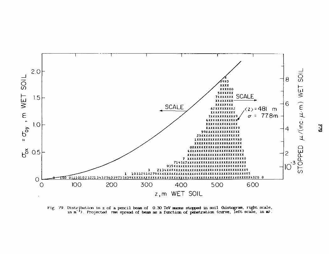
2.0 _J -0 Cf)
f- 1.5 w s: E ~
>- 1.0 bo II
x bo 05
9X5 xx xx xxxxoo
sxxxxxx 7XXXXXXX SCALE xxxxxxxx
SCA / xxxxxxxx
LE s2xxxxxxxx2 <z>=481 m 4~1---~~--~ xxxxxxxxxxx I
1xxxxxxxxxxx9 u = 77 Sm 'tXXXXXXXXXXXXX xxxxxxxxxxxxxx XXXX XXX XXXXX X X9
59XXXXXXXXXXXXXXX ZlXXXXXXXXXXXXXXXXX
lXXXXXXXXXXXXXXXXXXXO xxxxxxxxxxxxxxxxxxxxx
08XXXXXXXXXXXXXXXXXXXXX 4XXXXXXXXXXXXXXXXXXXXXXX3 xxxxxxxxxxxxxxxxxxxxxxxxx
7 xxxxxxxxxxxxxxxxxxxxxxxxxo 7143X7XXXXXXXXXXXXXXXXXXXXXXXXXX
935Xxxxxxxxxxxxxxxxxxxxxxxxxxxxxxxx l 2ll4XXXXXXXXXXXXXXXXXXXXXXXXXXXXXXXXXXX9
l l033253X279XXXXXXXXXXXXXXXXXXXXXXXXXXXXXXXXXXXXXXXX5 O I e I1l'([llilo1o2 3221343 2 so5 3975 5X59XX x xxx.x xx xx xx xx x xx xx xxx xxxxxxxxxxxxx x.x xxxxxxx xx xxxxx't 320 o I
0 100 200 300 400 500 600
z,m WET SOIL
Fig. 79. Dist.ribut.ic:n in z of a pencil beam of 0.30 TeV llll:l1B ~ in soil <histogram. riOit, scale, m m- 1). Project.eel nns spread of beam as a ftmctic:n of penet.rat,ic:n (curve. left, scale. in m).
_J
8 0 (f)
f-w :::::
6 ~
E :j__ u
4 c ~ ~
'--:j__
0
2 w Q_ Q_
10-3 8 (J)

3
_J
0 2 (/)
f-w 5 E
,... bo 1 II
>< bo
5
30
7 x
5X xx xx
xxxxx SCALE XXXX XXXXXXXXXXX5 .. xx x
xxxxxxxxxxxxxxxxx xxxxxxxxxxxxxxxxxxx
xxxxxxxxxxxx xxxxxxxxx l(z)= I 142 km xxxxxxxxxxxxxxxxxxxxxx -02 xxxxxxxxxxxxxxxxxxxxxx1 CJ - · 45k
X9XXXXXXXXXXXXXXXXXXXXXXX 5XXXXXXXXXXXXXXXXXXXXXXXXXX xxxxxxxxxxxxxxxxxxxxxxxxxxx xxxxxxxxxxxxxxxxxxxxxxxxxxx
7 5XXXXXXXXXXXXXXXXXXXXXXXXXXX5
2
_J
0 (/)
f--15 w
5 ~
E ::l
-3 u 10 c
' ::l 0 w Q_
X 7XXXXXXXXXXXXXXXXXXXXXXXXXXXXX Z7XXXXXXXXXXXXXXXXXXXXXXXXXXXXXXXXZ
3XXXXXXXXXXXXXXXXXXXXXXXXXXXXXXXXXXXX 1xxxxxxxxxxxxxxxxxxxxxxxxxxxxxxxxxxxxx xxxxxxxxxxxxxxxxxxxxxxxxxxxxxxxxxxxxxxz
775QXXXXXXXXXXXXXXXXXXXXXXXXXXXXXXXXXXXXXXX 05 Q_
0
0
159Xxxxxxxxxxxxxxxxxxxxxxxxxxxxxxxxxxxxxxxxxxx 3XXXXXXXXXXXXXXXXXXXXXXXXXXXXXXXXXXXXXXXXXXXXXX3
1 xxxxxxxxxxxxxxxxxxxxxxxxxxxxxxxxxxxxxxxxxxxxxxxxx 1 xz1oxxxxxxxxxxxxxxxxxxxxxxxxxxxxxxxxxxxxxxxxxxxxxxxxx
0 Z37X397XXXXXXXXXXXXXXXXXXXXXXXXXXXXXXXXXXXXXXXXXXXXXXXXXXXXX9 50 1ox12xxxxxxxxxxxxxxxxxxxxxxxxxxxxxxxxxxxxxxxxxxxxxxxxxxxxxxxxxxxxx1
J 517113597x x xxxxx xxpxxxxxx xxxxxx xxxxxxxxx xx xxx x~ xx xxx xx xx x xx xx x xxx xx xxxxxx xx.xx x xo 50
05 LO z, km WET SOIL
15
Fig. 00. Dist.r ibut:,icn in z of a pencil beam of 1. 0 TeV 111.J<IlS st:,cpped in soil <histogram, right:, scale. in m- 1). Project:,ed nns spread of beam as a flmcticn of penet.rat:,icn (curve, left scale, in ml.
f--(/)
21

3
_J
0 2 Cf)
I-w s: E ~
,., bo l ti
>< bo
5 1 x x
5 5 X2 X X
XXXX7X9X 2 ox xxxxxxxxxx
7 X2X3 xxxxxxxxxxxxo SCALE X 37XX XXXXXXXXXXXXXXTr-~~~__.
xxxxxxxxxxxxxxxxx XXXXXXXXXXXXXXXXXXX90
XXXXXXXXXXXXXXXXXXXXXX5 JX x~xxxxxxxxxxxxxxxxxxxxxxxxx XX~XXXXXXXXXXXXXXXXXXXXXXXXXXXl
xxxxxxxxxxxxxxxxxxxxxxxxxxxx xx <z> - l 986 km o nxxxxxxxxxxxxxxxxxxxxxxxxxxxxxxxx ( - ·
xxxxxxxxxxxxxxxxxxxxxxxxxxxxxxxxxx a = O .553 km XXXXXXXXXXXXXXXXXXXXXXXXXXXXXXXXXXXXXXl
9Jxxxxxxxxxxxxxxxxxxxxxxxxxxxxxxxxxxxxxxx xxxxxxxxxxxxxxxxxxxxxxxxxxxxxxxxxxxxxxxxxxx
, XXXXXXXXXXXXXXXXXXXXXXXXXXXXXXXXXXXXXXXXXXXXX5 SC.Al F ....-1X"xsxxxxxxxxxxxxxxxxxxxxxxxxxxxxxxxxxxxxxxxxxxxxxx5 ~xxxxxxxxxxxxxxxxxxxxxxxxxxxxxxxxxxxxxxxxxxxxxxxxxxxx
13XXXXXXXXXXXXXXXXXXXXXXXXXXXXXXXXXXXXXXXXXXXXXXXXXXXXX5 b7 xxxxxxxxxxxxxxxxxxxxxxxxxxxxxxxxxxxxxxxxxxxxxxxxxxxxxxxxx5
sxxxsxxxxxxxxxxxxxxxxxxxxxxxxxxxxxxxxxxxxxxxxxxxxxxxxxxxxxxxxxx b xx1xxxxxxxxxxxxxxxxxxxxxxxxxxxxxxxxxxxxxxxxxxxxxxxxxxxxxxxxxxxxxxx 3
77XX5XXXXXXXXXXXXXXXXXXXXXXXXXXXXXXXXXXXXXXXXXXXXXXXXXXXXXXXXXXXXXXXXXX9X 'o ~21 7 sxxxxxxxxx x xxxx x xx~ xxxxx xx xxxxxx xxx xx xxxxxxxx x xpx x xx xx xx xx xx xx xxx xx xx xx xxx x.x x s 251
0 2 3
z, km WET SOIL
Fig. 81. Dist.ributicn in z of a pencil beam of 3.0 TeV JlllilS ~ in soil <histogram. right scale. in m- 1). ProjecLed I1IE spread of beam as a f=cLicn of penet,raLicn (curve. left scale. in m).
_J -0
8 (f)
I-w s ~
6 E
:j_ u c ·-~
"-.
4 :j_
~ 0 w CL CL 0
2 I-Cf)
-4 10

_J
0 (/)
I-w S:
2 E -
>. bo II
x
bo
0
Fig 82.
7 7 IX X
I X7
I o X57X
SCALE
, SCALE. '"" (z) ~ 3.08 km
'7 0 ( ,a, ,,,,,,,.,,, x er ~ 0.893 km XXX91XXXXXXXXX XXXXXXXXXXXXXXXXXXX X
7xxxxxxxxxxxx xxxxxxxxxxxxxxxxxxxxxx1 x 70 77XXXXXXXXXX XXXXXXXXXXXXXXXXXXXXXXXXXZX 5
OXX XXXXXXXXXXXXXXXXXXXXXXXXXXXXXX X XXX5xxxxxxx xxxxxxxxxxxxxxxxxxxxxxxxxxxxxxxx5Xl
1xxxxxxxx xxxxxxxxxxxxxxxxxxxxxxxxxxxxxxxxxxxxxx11 xxxxxx xxxxxxxxxxxxxxxxxxxxxxxxxxxxxxxxxxxxxxxxxxxx
xxxxxxxxxxxxxxxxxxxxxxxxxxxxxxxxxxxxxxxxxxxxxxx
6 _J
0 (/)
5 f-w S:
4 E
3 ::l 0 c
2 " ::l 95jXXX XXXXXXXXXXXXXXXXXXXXXXXXXXXXXXXXXXXXXXXXXXXXXXXXXX xxx xxxxxxxxxxxxxxxxxxxxxxxxxxxxxxxxxxxxxxxxxxxxxxxxxxxxx x
1x1x xxxxx~xxxxxxxxxxxxxxxxxxxxxxxxxxxxxxxxxxxxxxxxxxxxxxxxxx1x51 ]Q48 Q_ xxxxxxxxxxxxxxxxxxxxxxxxxxxxxxxxxxxxxxxxxxxxxxxxxxxxxxxxxxxxxxxxx7x
xxxxxxxxxxxxxxxxxxxxxxxxxxxxxxxxxxxxxxxxxxxxxxxxxxxxxxxxxxxxxxxxxxxxxxxs b59XX7XXXXxxxxxxxxxxxxxxxxxxxxxxxxxxxxxxxxxxxxxxxxxxxxxxxxxxxxxxxxxxxxxxxxxxxxxx7~ 1
2 7977XX 9X XIX x xxx xxx x xx xx x xx x XX.4XX x xx xx xx xx xx xx.( xx x Xj,I{. xx xx xx xx xx x .. xx xx x x&xxx x .(xx xx xx x xxx xx xx x_,>\ 7 5 j j :LU
2 3 4 5
z, km WET SOIL
Dist.ributicn in z of a pencil beam of 10. O TeV lllJalS stDfFed in soil <histogram. right scale. in m- 1). Projected I1llS spread of beam as a fllllCticn of penet.raticn (curve. left scale. in m).
Q_
~ (/)
~

_J -0 (f) 2 I-w ~ . E
>,
bo II
>< bo
l 2X xx
5 z xx X5 XXl XX
l 9XX XXXXXX 0 X70XXX7XXXXXX X xxxxxxxx xxxxxzx
SCALE
0 XXXXXXXXXXXXXX 9X 3 5 x 3XXXXXXXXXXXX XXXXlX2X SCALE
7XXZXXXXXXXXXXXX XXXXXXXXXX • 7XXXXXXXXXXXXXX XXXXXXXXXXXX XXXXXXXXXXXXX XXXXXXXXXXXXXX55 (Z) = 3.73 km
55Z7XXXXXXXXXXX XXXXXXXXXXXXXXXXXX ( - l 07 k 5XXXXXXXXXXXXX XXXXXXXXXXXXXXXXXXXX <J - · m xxxxxxxxxxxx xxxxxxxxxxxxxxxxxxxxxx
7XXXXXXXXX XXXXXXXXXXXXXXXXXXXXXXXXO x xxxxxxxx xxxxxxxxxxxxxxxxxxxxxxxxxxx z
XX55XXXXXX XXXXXXXXXXXXXXXXXXXXXXXXXXXXX9Xl XXXXXXXX XXXXXXXXXXXXXXXXXXXXXXXXXXXXXXXXXX95
l 53XXXXXX XXXXXXXXXXXXXXXXXXXXXXXXXXXXXXXXXXXXXXX 9 x xxxxx xxxxxxxxxxxxxxxxxxxxxxxxxxxxxxxxxxxxxxxxx3 xo7x9xx xxxxxxxxxxxxxxxxxxxxxxxxxxxxxxxxxxxxxxxxxxxx3
9XXXXX XXXXXXXXXXXXXXXXXXXXXXXXXXXXXXXXXXXXXXXXXXXXXXXXX zxx xxxxxxxxxxxxxxxxxxxxxxxxxxxxxxxxxxxxxxxxxxxxxxxxxxxx5
7 XXXXXXXXXXXXXXXXXXXXXXXXXXXXXXXXXXXXXXXXXXXXXXXXXXXXXXXX957 Jxxxxxxxxxxxxxxxxxxxxxxxxxxxxxxxxxxxxxxxxxxxxxxxxxxxxxxxxxxxxxxx
xxxxxxxxxxxxxxxxxxxxxxxxxxxxxxxxxxxxxxxxxxxxxxxxxxxxxxxxxxxxxxxxxxxxx 0 0 1sx1~xxxxxxxxxxxxxxxxxxxxxxxxxxxx~xxxxxxxxxxxxxixxxxxxxxxxxxxxxxxxxxxxxxxxxxxxx131coooo
2 3 4 5 6
z, km WET SOIL
Fig. 83. Distribution in z of a pencil beam of 20.0 TeV lllll:nB st.cH>ed in soil <hist<Jgram, r~t scale, in m- 1
). Projected nns spread of beam as a function of penetration (curve, left scale. in m).
_J -
4 0 (f)
I-w ~ ~
3 E ::l... u c ·-~
2 ......_
~ ::l... 0 w Q_ Q_
10- 4 0 I-(f)
7

0 2 4 6 8 10 12
x ,m WET SOIL
Fig 84 Dist.nrut,ion in x of a pencil beam of 0.01 TeV Ill.JOOS stqipOO in soil (in m- 1). Fo:r ,...,t, soil use left, It b:M.an axes and fo:r dry soil use ngtit It top axes.

0
0.81-
_J -0 en ..... ~ 0.6
-E • ::l . (.,)
c 0.4 ·--....... ::l
0 w Q.
g, 0.2 ..... en
0
x, m DRY SOIL
2 4 6 8 10 12 14
CTox = CToy = 1.29 m
2 4 6 8 10
x ,m WET SOIL
Fig 85 Dist.ributian in x of a pencil beam of 0.10 TeV llll<'.nB ~ in soil (in m- 1). For wet soil use left & bottan axes and for dry soil use rig)lt & tq> axes.
I
0.6 _J -0 en >-a:: 0
-0.4 E
• ::l . (.,)
c 91 ·--.......
::l 0
0.2 ~ Q.
0 ..... en
12

0
_J -·.
0 en I-w 3: - 03 E . • ::t. 0 c: -...... ::t. 0.2
0 w a.. a.. 0 I-U)
0.1
0
x, m DRY SOIL
2 4 6 8 10 12 14
D"ox = D"oy = 2.55 m
2 3 4 6 7 8 9 10 fl
x, m WET SOIL
Fig ffi Dist.ribution in x of a pencil beam of 1.0 TeV 11UI1S stqpld in soil (in m- 1>. For wet soil use left l bottan axes and for dry soil use right l tq> axes.
_J -0 0.3 en >-a:: Cl -E • ::t.
0.2 0 c: ·--......
f4 ::t. Cl w a.. a.. 0
0.1 I-en
12

_J 0.3 0 en ..... w :: -E • ::t. 0.2 . 0 c --...... ::t.
0 w a.. a.. 0
0.1 ..... (/)
0
x,m DRY SOIL
2 4 6 8 10 12 14
o-0x = o-0 y= 2.92 m
2 6 7 8 9 10 11
x, m WET SOIL
Fig. ffl. Dist.ribut.icn in x of a pencil beam of 10 0 TeV IW<IIB stopped in soil (in m" 1) For ...,t, soil use left. II; bot.tan axes and for dry soil use r~t. II; t.op axes.
_J -0 en >-a:::
0.2 0
-E • ::t. . 0 c ·-- ~ ...... ::t.
0 0.1 w
a.. a.. 0 ..... en

_J
0 ({)
fw ~
E
er:
I
9 ,___
8 I-
7 ,___
6 I-
5 I-
4 I-
3 ,___
2 I-
l I-
I
5
+
+
+ 3
I
+
+
10
+ +
+ +
+ z 2 Z+22
I I
•
• •
• • +
+
+ • + •
++
+
.. Z+
• • • •
Z+Z
• •
•
• •
I
•
z + + ++ + +23+2++
Z+ Z+Z +ZZZ + + 24 +252233++ +
+ + +2 3+3642bB728827b2 + ++ +2 2B8BGCECJCFEEb3 +
+ + +22 3237b4EFTQVVVVVVJNOB + 53 2437AKFVOVVVVVVVVVVVMB82
++ +Z Z++4457779E"LVVVVVVVVVVVVVVVVLC + ++Z bZ79CF7AOJVVVVVVVVVVVVVVVVVVVVGb+Z +3+2 3396497HNFOVVVVVVVVVVVVVVVVVVVVVE52Z 2+355707~HGJMRVVVVVVVVVVVVVVVVVVVVVNf65
15 20 25 z ,m WET SOIL
Fig. 88. Scat,ter plot, of z and x for a pencil beam of 10 ()(X) lllJ<IlS of 0.01 TeV ~ in soil
-
-
-
-
-
ii -
-
-
-

_J
0 (f)
fw s: E
0::
9 I-
8 I-
7 I-
6 I-
5 I-
4 1--
3 I-
2 I-
l ,..._ • 2
•
' I I
+
' +
+ +
+ + +
•
+
• + +
+ +
••
+
+ ...
+ • +
• 2 +
• • •
• + + ++ ••• 2 2 +
+ ++++2 +2+++
+ + + -++2 2 + +2 • 2 • + 2 +
+ • + ..... +
+
• +
+•+224++++ 2 ++ 32+2+++++
+ 2+22• ··~23+++ + + + + ++ 244++ 22+
+ 2 + 3 +2 2223424 3++++3 +• 22 + +++2252•34•42+52+++3 +
+ ++ +32+2+3+463552537246342 + + + ++2 3 223261 659A688Zb2+-+
+ + 2 +3+2 3 4235778G9798B227L3+ + + + + + +2 3 3+ 245534ADFAG9HFH8C7033++
+ ++++ 2224 43533785AAClCELJHIOH08b52 ++ + +2 +2+ 3+333b4~b9EqGfK0PKKU0HMH6795+2
+ 2+ +++2+333647298A5GHflRJRVVVVVKVMFEA52 •2 ++ +3+ +++ 2++ 3 ~+33BbAb8~CCIOKUTVVVVVVVVTOJGC32++
+ ++ ++2+++42 4b4557980AAAKMHSVVVVVVVVVVVRVDbD3J + ++ Z+++o++ +3+27dd2A53C8JLHKKSVVVVVVVVVVVVVVTL068+ +
+ + + •3+++ 7+ 2 4-+23++3b27bHA81GMLVVSVVVVVVVVVVVVVVVVNID92 + + + ++2 +22 ++2 ~t++2,27J7JoU4o7A3D56GRPMVVVSVVVV~VVVVVVVVVVVTB853 +
• •2+ +++ J2••••••22z42J482~d6BCEGA&JM11vvvvv~vvvvvvvvvvvvvvvP£c12 • + 2 ++ ++2++2 3+3~2454 ~4++88A 3AU5F7FGMH8VVVVVVVVVVVVVVVVVVVVVVVSMK963
+ ~ + + + 2 +23+4~24d3+9352H~C79AMAELHORHVRVJVVVVVVVVVVVVVVVVVVVVVUE6t++ + t+ + + ++ 4++ ~22326435Ab9Jj7Y0d7JU~OLGPOUSVViVVVVVVVVVVVVVVVVVVVVUJE6+ ••b++3 ++ + 2 323l6l?52+;454~8CUDBEA5FGH~HVVVVVVVVVVVVVVVVVV~VVVVVVRJ7b++
50 100 150 200
z ,m WET SOIL
-
-
-
-
-
-
-
-
-
Fig 89. Scatter plot of z and x for a pencil beam of 10 000 IDJCSlS of 0.1 TeY stq:Jped in soil.
$

_J
0 en
1-w 5
E
0::
1--
>---
1--
1--
1--
I-
1--
>---
>---
0
r J + + 2 + I
+ 2 + + +
2 +2 ++ + + + + + + + 2 • •
+ • + ++ • ++ • • 2 2•
+ + • • + 22 + • • • + + + ++ + • •••+2+•+•2
+ + + + 2 + 2232 ++ • ... • • + 322+23 32++ • • • + •2• •2
• 2 3 • 2 ++ 32 + 4++2 + ++ • • + • ]+ 43+ 03 3+3 2++
+ + + 2 3Z22 2• • +42••2 + ++ •22 ... •2 + 4• 32224 2 ..... + +
• + 2 2 + 2 3•+3+324+3+4+4•• 2 + • + + 3 +.23+235b+3222+3 22524+
+ + ++ +++++ +•••2•22•24b2~3b2+•5+5+23 2 + + + ++ 2+•3 34243+55233232363+3 z
Z + 2 + 2 22 ++22553A25754473~•t3+223++ • + + z 3 223++2533055326456757683•4•2
+ ++++ 2 +++2+ 2 33543+332343649(845895•3• + ++ ++ 2++ ++ +23 2++26+14293BB2384~36866B2 5222+
+ + 2 + 22 + +•22+23+2 53436258b346364b~B88B7363+++ ++ + +++++ +42 b2+)24+627375b665558bAb73476B72742+2 +
+2 +• 222 +•+3+34+3+3334+55j988A56A678999B476+ 2+2 + + + ++22 4+22• 2+•2427234277A9C729958EAA6H99B677244++ +
+ • • 32 252+462+654•48d4+533975CCB9DOEC7E65GE89o77•2 + + •+ 2+4++2 +++24 ~3224876285b97ffCCEAEHFH~BDEBbB5432+++ 2
+ +•22+32+++3++222324b384bFCBC9EAAC~NS£CNJE099AA7,72+ + + ++ z+z 2222 223355)44,33b5b747BODJ~GliH~S~fKHJlHHG~7~45+33• +
+ + + + + 2 2++5345+o554753438907EBC9dfLFIHHffMPlCICUB7'7423++ • •22 ++ +4+42+ 444743947bb7U7CBMBLGLEIJLLHISPKGlAMHeEce12+22
2+ ++ + +22+4 2532B445584743~bBC88CHFDFJIJVHMKJOVVUROKIRIHDF,3742 + + Z Z +3 24++55jbb7+5373600btl3AOCEl£FMlM?IVLH~VJLCVJPJGHlOB99 + +++ +++ 3J233243343+2Bb4bf57b5DA6B~AIEIGGNH~JRPHVPNJVTR~lKJPGEHb323
+ + 2 ++ +43433++b533b455b54499b769rlE~9FlSJHLNlP~NSJVVUVSVUOVSHBIICAC7+2++ + l ++++42•+32llb3+3045b339bA9bACCEGAGfnGKPNOUPlONSVPUIVVVVVR"GIEC6b55 ++2
2 + + ++24 + Z7b+2b2+4+35b9b5fA4CC&9UBGC9LPVGHE~RVVRVVUVV~VVVVVVUVEJD~545 + + + 2 ++ +Z ++ 4233 4377425b24353CDC5bbD5AAJCKllfLlJJHVKSVVVSVKVVVVVVVVOVQOONBAC3+3+ + + + +2 4J32535+2~+bZl+bbAbb98B8Cb67COCCJEBMC~OOUVTRVVVlVTVTVVVVVVVTVLHJA6A9323 + + ++3 + ++23223324+24577A354A89AGGEC8JCGKKlBlK~~VVU~SSVVVVVVVVVVVVUVRTOIMAAB+2 3 + + + 5+53 3+2b435A7~Eb4475bCDQC7EDFGlIHHHHVLVMVflVVVVTVSVUVVVVVVVVMVlRFD4b22+
3+2+ 3+3•+~ 2•83+d6b72246977b68FAJC9FQFJElPGFJKJUUQ$TVVVVVVTVVVVVVVVVVVLPHH6B+ J + 4+2 2+ ++4bo2b44467+8U4b694BbFA7tFI8IAINKONufTS~KW~JVVVVVVVVVVVVVVVVVVVVTHCCC32+ + + 3+2 4+++223423423 +b5379d4648479B7C5FA6FPJllPAJ~PPNNJVVVVVVVVVVVVVVVVVVRTNUKEB524+ +
732 2 ++324245+8452~38+7745bCEfCijAKlffJNGLHKGPPR~T"HVVVVVVVVVVVVVVVVVVPMN~G~~9t2+
05 1.0 1.5
z, km WET SOIL
-
-
-
-
-
-
-
-
-
Fig. 90. &at.ter plot. of z and x for a pencil beam of 10 000 lllJalS of 1.0 TeV st.opped in soil.
~

_J
0 (f)
I-w 3:
E 0:::
9
8
7
6
5
4
3
2, 2
• .. • •
•
•
•
+
• •
+
+
• •
•
•
• +
•
• + .. •2 +
• + •• • • • + • 2• • • • .. • • • • • • •
• •2 • • • • • • • • • 2 .. • • • •
• 2 • z + • .. t
• • • • • .. • .. • • + +++ + +. + + • • + + +++++ + ++ • • •
• + 2++2 + + +++ + + • + 2 + + + • 3 + + 2 + + + • •• ++++ + " + +4+ 4+++ 2 + ++ + •
• + +++ +++ 2 + + + +++ + + + + +++ + • + • 2 • .. + +++ 2 ++++2 2+ 3322++ + + 22 + + 2
• • • • + + + 2 2 2 +22 + + •• ++ +2 ++ + + • +-t++ + +22 3 +++ + +2+ 22+ ++++3++ +2 ++ +++++ •
• 2 + + +2 3++ 2++++3++++3+222+++2++++3+ 2+2+ 2 22 + ++ +++2++ 2++++222+2 2 22 2222+ +222+33++24 2 +22+ ++ + + + 2 + + + 22++ + + •232+ + 3+ ++32 23++2~++32+2+ +3 + + •
••2 *'* ]f>+ .. +J4 •3 23+223+3b234+2+33223322+ ++22 + .... + Z+ + +2 ++222 ++2+•+ 32~442+33~+33354+33+3+~• 2 33 + 2 3 1'
++2 + + + + +3+ +32++3++ 3•22 2 52 3433 3223336++53++2+ 22 + +2+ ++ 3+3+ 3 + ++23 2332+22+5432+2245+475555~+~423t34++24+Z22++ + ++
+2 + + +-t+Z +2++2+345+3 2't2't4't 't37*46&+ 'i433•'5227+434+4 242 2 324 +• 2 + 2++2++3 3++Z+43+3+Z++43553ABZ4 75b3b4bbA3Z336t5+2325 Z3+ 52 +
+++3 +2+3+2+ 3 ++2+2 43333325255j4b3+565,59bbt443343+32432 ++23+ 2 ++ + + 2++++ +++32 20+423224+ 53227243828434b27b43+b~7b+4o78354+Z2+4+++ +
++3+ + ++ +322•2+ ++b23444+225456635353537b4b55432bb7bdQ4232636 ?222+2 + ++ Z 3 23434323533+243+2 2bb5A3dA38792ci58b7344363~7t33+42t3~4+ 32 3 ++
++ ++++Z+3+323554+34bQ5444ZZ+Q5Jd4+b85487A586~b88~344b4~bA8754b3+322 ++2++ +Z+l+l+++ 24+53+~74+782~343277+54bbdbbCQ66bb6DA7bb806AQ967552754t23t+22+22 •
+ 2 3 2 2+224+222 442t24b3b74bb4325749AB3AC458j88E9A760A97C7366~534,455 3223 2+• + 3+ 2+3 + 2 +5 +3+bo42848384A9552889A80d984929AEE96CCBCbbG7934b5BZ29732+3+ 2 +
• +
2• 2
+ ++ziz 3+3Z+33b445282~b9b75BCb777BAF7CCC7C6dGAOAC978BBbCQ556b76A88A7283+23+2t+ ++ +tt+ 2224264+452432 450B77b7l91~BAqQAoABD84ACAKDEKE~DBb886A83q79433oa14z44 t2
2 • 2+ +++43322 +3+2523qb6B859BB5'r98BBQ75.;cAA9a09ABLBEHJ7HFbFCHbAE7oD879Q43374 42+2.Zi +3++++3 2 24b2233+4~4b7ABB4B4~0HC7~CDE9EE1JMEDACCDGflDCBCJ7EG8GCFB56479b3C5724 24+•3
+ +++ +2+2t 55++5434 bBb5BCA5bBDFQBBCCCA7DJDSHEIAAFEEHFOHBGHOHBEFHFBA784bC599423434 2•31· ++t2 + 5+3 J42524536255bbC9G8AAKQ8KQOaEFHLJHEON~llf~CKKRDEEBFGDDJBGbAQ8B72AA356522
+ + 2 23+3457++~~45l576QK6Cti0966ASCHOGCAHIFCCElODLDHF9Mf3fJOfG~GFC9~AH~7847b54b2252632 +2++ + •2•35+22343bJ955b54QH9B88BHUJCIELULJOCO~LJECOHHNDICUEGJJJK~JCCAAABC8~558+6825332J2 + +++ +2+562+32324543d9Ab7CCG9AK~OFGCC510CBCNLFFKC~LBLUGI~LRDKMOFBLHIFOGGBA8ABA7b245 ++ 22+ +3+++++~ 5b~4Ad7dH9(q70FF8lKAF8HlJfHIIR~J5EJS£CNChJUMJKGK~Q~PKlJCCBBA59AB7b~5437535++ + 5 +3•++2~444b75AA4b9AQA8ECJICUdB~lJPHEEAURFMIVJMJPJKJ~MSNRC5BIGJJJh0JflCC749A35Jb3++
+ 232322 742ooB7d7QH74FCAAHCiaEKLTKO~OHIPOJKPKKFQO~MTLIPPHNFKIHQEKNQKAEL6q07Cb26542bt2 + + +++• ++4+2JJ4dHdCBEAbCFOBC4ARfLJMLDK~fFKNJllK~VNlQUURUUN~VMJCKKONKOGHPDlfFEf57~443742+ J +t + 542772b69d7YoGffijAfOSHHHFNJHALHCKHILLt.JOP~OJNlPVVVEDHKNOPMFGQJJOCJQBCA6~5634443+•+ +35 24•2++t832oC8A)87(CCFEBMBOG0JMllNPNLHHTURUSVhlNKKUT~VPVNJNUMPKM0MfLAfHQKBQBb345+ 2242
+ t24JJ32+7od+45b07BC7~FCECJCEKU~lrlMNVRILVlTT~~~H1ibKLN~HlPJ~RMLTONPJPIHCFDGCOCA783455254+ t2.J2 .i7 7 J g Q4;:: 7C t!9 .\97(.at.li~_\lJ!.DJ! 0 Sl_!l\J 0 0 IL VtJR JP L V ~ VKl1VP V QUON~ S SM :JI V DL K V9f I FK E J BC AA 2b2 3 5b • + 2 2
2 3 4 5
z , km WET SOIL
Fig. 91. Scatter plot of z lllrl x for a pencil beam of 10 000 Dl.llilB of 10.0 TeV ~in soil.
~

8
_J
55 6
1-w s
E 4
er
2
5 10
z ,m DRY SOIL
15 20 25
10-16
10-15
10-14
10-13
10=i2
30
o~---
5 10 15 20 25 z, m WET SOIL
Fig. 92. Cai.tours of eqial energy density (in GeV/cm3 •incident IJll(ll) far a poncil beam of 0.01 TeV rrucru; incident cn solid soil cylinder aloog the axis. Ccntarrs far wet soil Cleft It bot.tan axes) are integral ~s of ten. Cent.ours far dry soil <right It tq> axes) rrust be scaled down by 0 52 as shown for cne exanple. Sane ccntours may be emitted for clarity or due to statistical tmcert.ainty.
35
12
10
8 _J
0 (f)
6 >-er 0
E
4 er
2
~

8
~ 6~ w 5 ~
E
er 4 r
2 f-
z ,m DRY SOIL
50 100 150 200 250 300
12
10
/ 5·2·10-17 10-16
\ J 8
/ / \ \ 16 . . ·- .
I / ~\\ j4 10 -
// ,/ ~ 10-13 • . . ' '2
50 100 150 200 250
z,m WET SOIL
Fig. 93. Cent.ours of eq.ial energy density (in GeV/an3•incident DlJ(Xi} for a pencil beam of 0.10 TeV JDJOnS incident. en solid soil cylinder aloog the axis. Cent.ours for ...,t, soil <left. .t bot.tan axes) are integral ix-rs of ten. Cent.ours for dry ooil <right .t top axes) ftlJSt. be scaled down by 0.52 as sholinl for cne exaq>le. Sane cent.ours may be cmit.ted for clarit.y or due t.o stat.istical uncertaint.y.
_J
0 (/)
>-0::: 0
E - I
0:::

9
8
7 _J
~ 6 I-w s: 5
E - 4 er
3
2
Fig 94
0.5
05
z, km DRY SOIL
1.0
10-12
10
z, km WET SOIL
15
5·2·1617 ..----
2.0
I. 5
O:ntours of eq.Jal energy densit.y (in GeV/an3•incicient, m.oV for a pencil beam of 1.0 TeV llU<I1S incident. <II solid soil cylinder ala>g the axis. O:ntours for wet. soil (left, It. bot.Inn axes) are integral Jl<M"TS of ten. O:ntours for dry soil Cright. It. tq> axes) oust, be scaled ~by 0.52 as shown for <Ile exanple. Sane C<I1tours DBy be cmit,t,ed for clarit.y or due w st.at.istical Wlcert.aint.y.
12
10
8 _J
0 (f)
>-6 er
0
E ~ -4 er
2

z, km WET SOIL
2 3 4 5 6
I / '\ 9
8 l I - fi:;.?.J()-1~ _17
7 I I / ~IV \
6 \ \ _J
0 (/)
5 t--w 3 4
10-14 E I I I / --------..... er 3
2 l //// 10-13
0
. . ..
2 3 4 5
z, km WET SOIL
Fig. 95. Centaurs of equal energy density (in GeV/an3•incident. OIXIl) for a pencil beam of 10.0 TeV nuons incident. en solid soil cylinder al~ the axis. Centaurs for wet. soil (left. .l bot.t.cm axes) are integral poirers of t.en. Centaurs for dry soil (right. .l t.q> axes) oust. be scaled down by 0.52 as shown for ene ex:anple. Scme centaurs nay be anit.t.ed for clarity or due t.o stat.ist.ical WlCert.aint.y.
12 I
j 10
I 8
I _J -0 (/)
6 >-0:: 0
ii E .
4 0::
' 2

_J0.7 0 Cf)
1-06 w !.: - 0.5 E :.:!.. u 04 .£ ~
.......
~ 0.3 l9 . >-I- 0.2 Cf)
z w 0 0.1
>-l9 0:: w z w
Fig. 96.
FRACTIONAL ENERGY LOSS
222121
IONIZATION BREMSSTRAHLUNG
xxxxxxooenee7o1••&4'JH212110 PAIR PRODUCTION xxxxxxxxxxxxxxxxxxxxxxxxxxxxxx9~987bb54422110 xxxxxxxxx x xxx xxxxxxxx xxxx xx xx xx xx xxxxxxxxxx xx ooeo,. 1210 DEEP INELASTIC XxxxxxxxxxxxxxxxxxxxxxxxxxxxxxxxxxxxxxxxxxxxxxxxxxxxxxxY7b4ZO xxxxxxxxxxxxxxxixxxxxxxxxxxxxxxxxxxxxxxxxxxxxxxxxxxxxxxxxxxxxes10 xxxxxxxxxxxxxxxxxxxxxxxxxxxxxxxxxxxxxxxxxxxxxxxxxxxxxxxxxxxxxxxxxb2 xxxxxxxxxxxxxxxxxxxxxxxxxxxxxxxxxxxxxxxxxxxxxxxxxxxxxxxxxxxxxxxxxxxa2 xxxxxxxxxxxxxxxxxxxxxxxxxxxxxxxxxxxxxxxxxxxxxxxxxxxxxxxxxxxxxxxxxxxxx5 ixxxxxxxxxxxxxxxxxxxxxxxxxxxxxxxxxxxxxxxxxxxxxxxxxxxxxxxxxxxxxxxxxxxxxao xxxxxxxxxxxxxxxxxxxxxxxxxxxxxxxxxxxxxxxxxxxxxxxxxxxxxxxxxxxxxxxxxxxxxxxxo xxxxxxxxxxxxxxxxxxxxxxxxxxxxxxxxxxxxxxxxxxxxxxxxxxxxxxxxxxxxxxxxxxxxxxxxx xxxxxxxxxxxxxxxxxxxxxxxxxxxxxxxxxxxxxxxxxxxxxxxxxxxxxxxxxxxxxxxxxxxxxxxxxq xxxxxxxxxxxxxxxxxxxxxxxxxxxxxxxxxxxxxxxxxxAxxxxxxxxxxxxxxxxxxxxxxxxxxxxxxx~
Xxxxxxxxxxxxxxxxxxxxxxxxxxxxxxxxxxxxxxxxxxxxxxxxxxxxxxxxxxxxxxxxxxxxxxxxxxx xxxxxxxxxxxxxxxxxxxxxxxxxxxxxxxxxxxxxxxxxxxxxxxxxxxxxxxxxxxxxxxxxxxxxxxxxxx1 xxxxxxxxxxxxxxxxxxxxxxxxxxxxxxxxxxxxxxxxxxxxxxxxxxxxxxxxxxxxxxxxxxxxxxxxxxxx xxxxxxxxxxxxxxxxxxxxxxxxxxxxxxxxxxxxxxxxxxxxxxxxxxxxxxxxxxxxxxxxxxxxxxxxxxxxa xxxxxxxxxxxxxxxxxxxxxxxxxxxxxxxxxxxxxxxxxxxxxxxxxxxxxxxxxxxxxxxxxxxxxxxxxxxxx ixxxxxxxxxxxxxxxxxxxxxxxxxxxxxxxxxxxxxxxxxxxxxxxxxxxxxxxxxxxxxxxxxxxxxxxxxxxx1 xxxxxxxxxxxxxxxxxxxxxxxxxxxxxxxxxxxxxxxxxxxxxxxxxxxxxxxxxxxxxxxxxxxxxxxxxxxxxx xxxxxxxxxxxxxxxxxxxxxxxxxxxxxxxxxxxxxxxxxxxxxxxxxxxxxxxxxxxxxxxxxxxxxxxxxxxxxxb xxxxxxxxxxxxxxxxxxxxxxxxxxxxxxxxxxxxxxxxxxxxxxxxxxxxxxxxxxxxxxxxxxxxxxxxxxxxxxx xxxxxxxxxxxxxxxxxxxxxxxxxxxxxxxxxxxxxxxxxxxxxxxxxxxxxxxxxxxxxxxxxxxxxxxxxxxxxxx5 Xxxxxxxxxxxxxxxxxxxxxxxxxxxxxxxxxxxxxxxxxxxxxxxxxxxxxxxxxxxxxxxxxxxxxxxxxxxxxxxx xxxxxxxxxxxxxxxxxxxxxxxxxxxxxxxxxxxxxxxxxxxxxxxxxxxxxxxxxxxxxxxxAxxxxxxxxxxxxxxxb xxxxxxxxxxxxxxAxxxxxxxxxxxxxxxxxxxxxxxxxxxxxxxxxxxxxxxxxxxxxxxxxxxxxxxxxxxxxxxxxx3 xxxxxxxxxxxxxxxx~xxxxxxxxxxxxxxxxxxxxxxxxxxxxxxxxxxxxxxxxxxxxxxxxxxxxxxxxxxxxxxxxx3
xxxxxxxxxxxxxxxx~xxxxxxxxxxxxxxxxkxxxxxxxxxxxxxxk.x.A.xxx~xxxxxxxxxxx~~xxxxxxxxKxxxxxx
0.972 0.037
-4 8·8 ·10
-4 9· 7·10
20000
5 10 15 20 25 z, m WET SOIL
Radially integrated energy density (in GeV/an•incident DDl) 1RKI1S incident en solid soil cylinder (of infinite radius).
far a pencil beam of 0.01 TeV
~

'--
'--
-
(j') (f)
g >-(.!) 0:: w z w ....J <I z Q f-
~ 0: u..
l I ro
<D ID O O'l oo ro C\J o ~Q oo 00 00
I I I I
~ i! 0
;;' ~ ~
~~
(!) z u .o~: Z -D><X)( o- ' => - ~ N><;;:::; ..J ._en -><~:::::::..: ~ U<:X O"~::::::::::c q ~~ N><><X><X><K><X)()()(X
Z ~Ow ~~:::~:::::::::: O ....... Oz ~!:::::~:::::::::: ~ ~ ~- ~=::::::::::::::::: ~ (f) ~ ~><><xxxx><><X><XXX><X><><><>< N~ ~ oxx><xxxx><><><><XX><xxxxxx
- w ~w o~=~==~::::::::::::::: z ~ ~w ~==~:::::::~:~;::::::: 0 CD Q..O Mxxx><><><><xx><x><><><><xxxxx><x - .axx><><><><><><><><><><><><><xxxxxx:~
~xxx><><x><X><><XXXX><><X><><x>< Nxxxx><><x><><><><XXXXX><XX><><X ~xxxx><><x><><><><><><><><><><><><><x><x ~xxxx><><><><><><><x~xx><xxxxx><>< ~xxx><><><><><><><><><><><><><xxxxx><><
-><xxx><X><x><><><XXX><XXXXX><><XX ~><xxxxxxxx><xxxxxxxxxxx><X>< n><><><><><><><x><><><X><X><><Xxxxxxxx ~><xxxx><><><><><x><><x><X><><><><><><><x ~><xxxx><X><XXXXXXXXX><XXX><><x
O><><xxx:oc><XXXXXXXX><X><><xxxx><x -x><xxxxxxxxxxxxxxxxxxxxxxx ~xxxxxxKxxxxxxxxxxxxxxxxxx ~xxxxxxxxxxxxxxxxxxxxxxxxx ~xxxxxxxxx~xxxxxxxxxxxxxxx ~xxxxxxxxxxxxxxxxxxxxxxxxx ~xxxxxxxxxxxxxxxxxxxxxxxxx
~xxxxxxxxxxxxxxx~xxxxxxxxxx ~xxxxxxxxxx~xxxxxxxxxx~xxxx
~:~~:~~~~::~~::::~:=:~~~~~~ ~xxxxx~xxxxxxxxxxxxxxxxxxxx ~xxxxxxxxxxxxxxxxxxxxxxxxxx ~xxxxxxxxxxxxxxxxxxxxxxxxxx ~xxxxxxxxxxxxxxxxxxxxxxxxxx ~xxxxxxxxxxxxxxxxxxxxxxxxxx ~xxxxxxxxxxxxxxxxxxxxxxxxxx ~xxxxxxxxxxxxxxxxxxxxxxxxxxx ~xxxxxxxxxxxxxxxxxxxxxxxxxxx ~xxxxxxxxxxxxxxxxxxxxxxxxxxx NXxxxxxxxxxxxxxxxxxxxxxxxxxx ~xxxxxxxxxxxxxxxxxxxxxxx~xxx ~xxxxxxxxxxxxxxxxxxxxxxxxxxx ~xxxxxxxxxxxxxxxxxxxxxxxxxxx ~xxxxxxxxxxxxxxxxxxxxxxxxxxx oxxxxxxxxxxxxxxxxxxxxxxxxxxx ~xxxxxxxxxxxxxxxxxxx~xxxxxxx •••••xxx"xxxxxxxxxxx•xxxxxxx ~xxxxxxxxxxxxxxxxxxxxxxxxxxx
oxxxxxxxxxxxxxxxxxxxxxxxxxxxx ~xxxxxxxxxxxxxxxxxxxxxxxxxxx~ ~xxxxxxxxxxxxxxxxxxxxxxxx~xxx Nxxxxxxxxxxxxxxxxxxxxxxxxxxxx ~xxxxxxxxxxxxxxxxxxxxxxxxxxxx ~xxxxxxxxxxxxxxxxxxxxxxxxxxxx ~xxxxxxxxxxxxxxxxxxxxxxxxxxxx ~xxxxxxxxxxxxxxxxxxxxxxx~xxxx 4XXMXXxxxxxxxxxxxxxxxxxxxxxxx ~xxxxxxxxxxxxxxxxxxxxxxxxxxxx ~xxxxxxxxxxxxxxxxxxxxxxxxxxxx ~xxxxxxxxxxxxxxxxxxxxxxxxxxxx ~xxxxxxxxxxxxxxxxxxxxxxxxxxxx
oxxxxxxxxxxxxxxxxxxxxxxxxxxxxx ~xxxxxxxxxxxxxxxxxxxxxxxxxxxxx ~xxxxxxxxxxxxxxxxxxxxxxxxxxxxx ~xxxxxxxxxxxxxxxxxxxxxxxxxxxxx MXxxxxxxxxxxxxxxxxxxxxxxxxxxxx ~xxxxxxxxxxxxxxxxxxxxxxxxxxxxx ~xxxxxxxx><xxxx~xxxxxxxxxxxxxxx
'~: ~ ?,'! ~.: ~ ~ ~ :l~ ~:: ~:::: ~-~: ~: ~ : >< xx x
C\J
lJOS l3M (W·rl.:>UJ)/f\&8 'J..l1SN30
0 LO C\J
0 0 C\J
0 tD
0 0
0 LO
....J 0 CJ)
I-w ~
E N
~ "' 0 .... 0
"O
J ..... .....
! ~
a ... 1~ ~~ ~M .....
·~~ e· ~11 ~ 'S .S""
i~ !'&
.....
i! ..... g
ls ~~ .;i ..... >. ~ ......
j~ bi .~ t:..

_J
0 (f) 1-w 3 1.5 ~
E
::l cj c
..... 1.0 ~ l9
>-I(f)0.5 z w 0
>-l'.)
n: w z w
I
51 XX851 (XXXX8j2 XXXXXXXX9b30 XXXXXXXXXXXX741 XXXXXXXXXXXXXXX6oZO 1*xxxxxxxxxxxxxx~xxx14z XXXXXXXXXXXXXXXXXXXXXX974l XXXXXXXXXXXXXXXXXXXXXXXXXX974l xxxxxxxxxxxxxxxxxxxxxxxxxxxxxx974Z xxxxxxxxxxxxxxxxxxxxxxxxxxxxxxxxxx9752o XXXXXXXXXXXXXXXXXXXXXXXXXXXXXXXXXXXXXXX6b3l
I I
FRACTIONAL ENERGY LOSS
IONIZATION BREMSSTRAHLUNG PAIR PRODUCTION DEEP INELASTIC
0.580 0.193 0.168 0.055
xxxxxxxxxxxxxxxxxxxxxxxxxxxxxxxxxxxxxxxxxxxeoJl xxxxxxxxxxxxxxxxxxxxxxxxxxxxxxxxxxxxxxxxxxxxxxx9b31 xxxxxxxxxxxxxxxxxxxxxxxxxxxxxxxxxxxxxxxxxxxxxxxxxxxboJO tx-xxxxxxxxxxxxxxxxxxxxxxxxxxxxxxxxxxxxxxxxxxxxxxxxxxxxxxasz xxxxxxxxxxxxxxxxxxxxxxxxxxxxxxxxxxxxxxxxxxxxxxxxxxxxxxxxxx9740 xxxxxxxxxxxxxxxxxxxxxxxxxxxxxxxxxxxxxxxxxxxxxxxxxxxxxxxxxxxxxx74l xxxxxxxxxxxxxxxxxxxxxxxxxxxxxxxxxxxxxxxxxxxxxxxxxxxxxxxxxxxxxxxxx140 xxxxxxxxxxxxxxxxxxxxxxxxxxxxxxxxxxxxxxxxxxxxxxxxxxxxxxxxxxxxxxxxxxxx730 ~xxxxxxxxxxxxxxxxxxxxxxxxxxxxxxxxxxxxxxxixxxxxxx~xxxxxxxxxxxxxxxxxxxxxx13 xxxxxxxxxxxxxxxxxxxxxxxxxxxxxxxxxxxxxxxxxxxxxxxxxxxxxxxxxxxxxxxxxxxxxxxxx9b2 xxxxxxxxxxxxxxxxxxxxxxxxxxxxxxxxxxxxxxxxxxxxxxxxxxxxxxxxxxxxxxxxxxxxxxxxxxxx9o3o xxxxxxxxxxxxxxxxxxxxxxxxxxxxixxxxxxxxxxxxxxxxxxxxxxxxxxxx~xxxxxxxxxxxxxxxxxxxxxxab~12uoooooco
0.5 l.O 1.5
z, km WET SOIL
-
-
-
Fig. 96. Radially integrated energy density (in GeV/an•incident. nucn) for a pencil beam of 1.0 TeV JruOOS incident. Cil solid soil cylinder (of infinite radius).
~

_J
0 Cf)
fw 3: ~
E 7
r I I I
::t 8 ~~~z FRACTIONAL ENERGY
IONIZATION BREMSSTRAHLUNG PAIR PRODUCTION DEEP INELASTIC
u c -' ~ (.!)
>-1-
XXXX5 XXXXX70 XXXXXXX3
6 IXXXXXXXX70 XXXXXXXXXX5 XXXXXXXXXXX63 XXXXXXXXXXXXX72 XXXXXXXXXXXXXXX73
4 1XXXXXXXXXXXXXXXXX84 rxxxxxxxxxxxxxxxxxxx95l XXXXXXXXXXXXXXXXXXXXXX84l XXXXXXXXXXXXXXXXXXXXXXXXX741
Cf)
z 2 w
XXXXXXXXXXXXXXXXXXXXXXXXXXXX652 XXXXXXXXXXXXXXXXXXXXXXXXXXXXXXX97420 Xxxxxxxxxxxxxxxxxxxxxxxxxxxxxxxxxxxx7531 XXXXXXXXXXXXXXXXXXXXXXXXXXXXXXXXXXXXXXXX97b420 xxxxxxxxxxxxxxxxxxxxxxxxxxxxxxxxxxxxxxxxxxxxxx98654210 xxxxxxxxxxxxxxxxxxxxxxxxxxxxxxxxxxxxxxxxxxxxxxxxxA.xxxx~87054322100
0 10
I
BALANCE
0.167 0.335 0.388 0.110
>(.!)
XXXXXX XX XX XXXX XXX XX X,X XXXX XXXX XXXXXXX XXX X.XX X XX XX XX AX XX XX X XX XX).XX XX X9 8 6 7bb5 ~'t 4 4 3 32,2221111 0000000000000,(JCOO 00 o
er w z w
2
z, km
3 4 5
WET SOIL
-
--
-
-
--
Fig. 99. Radially int.Egrat.ed energy density (in GeV/an•incident DUal) far a pencil beam of 10.0 TeV 111.JCilS incident en solid soil cylinder (of infinite radius).
~

_J
0 (/)
1-w 3
E 0:::
15
10
5
0 0
z, km DRY SOIL
1019
1017
1 z ,km WET SOIL
2
1621
15
10
5
0 2
_J -0 (/)
>-0::: 0
E -0:::
Fig. 100. O::ntours of eq.W dose eq.rivalent (in rem/incident protaV due to nu:ns far a beam of 5 TeV protais incident oo a solid soil cylinder. MuaJS generated by both hadroo and electrcmagnetic cascades are included. O::ntours far wet soil <left I: bot.tan axes) are integral f<Jlft'I"S of ten. Cent.ours for dry soil <riW!t I: tq:i axes) llllSt be scaled cbm by 0. 65 as shown for cne """"Ple Sctoo centaurs may be emitted for clarity or due to statistical =certainty.
'>! ...... 8

_J
0 Cf)
1-w 3:
E . 0::
15
10
5
0
z, km DRY SOIL
2 3
, ' I T l-=cflrr~--,------.-.-+ I I - I ' -- l
-
- -t--1---_L_ -' -L -f--1.-_ r-- 10-22 ,_ __,, : - " - 10-" "
-
- - r:--. t---h- "'--1;:-f"~-- 10-20 "
'-- -.__.____ -~ ~ ~- ~ 10-19 ' ' -~ '- 16.5 -10·19 - - "-.. ~ "' -..... ""- -
' -- ~ -~' 10-" c --......_
' 10-1•-;c-._--. 1cr
1BT......____ '--...
~"'\ 10~5,_I~ ------ ~ -\.'-.:: __,_ ~ - --~ '- ' --i-- ~ "' ~ ~-
2
z ,km WET SOIL
3
15
_J
0 Cf)
10 >-0:: 0
E -0::
5
Fig. 101. Centaurs of eq.ia.l dose eqrivalent (in rem/incident protaU due to ntJCrul for a beam of 10 TeV protcris incident <II a solid soil cylinder. Muoos generated by both hadrcn airl electrcmagnetic cascades are included Centaurs for wet soil (left .t; bottan axes) are integral ix-rs of ten. Centaurs for dry soil <r:ifJit .t; tcip axes) lllJSt be scaled doim by 0. 65 as shown far <IIe exanple -Sane c<IItaurs may be anitted for clarity or due to statistical uncertainty.
'Tl ..... 0 .....

z,km DRY SOIL
~
15
10 _J
0 (/)
10-20 _J
0 (/)
I- 10 >-w ~
10-19 n:: 0
E E . . n::
5 n::
~ I io-17 I ~j I ~' 15
10-16
I~ I '1 --, A~ I~ o I ~-13 10 2 3 4
z ,km WET SOIL Fig. 102. fult.ours of e<Jia1 dose eq.rivalent. (in rem/incident. protcn> due to IJl.JCllS for a beam of 20 TeV
protais incident. en a solid soil cylinder. Mums generated by both hadrcn and elect.rcmagnet.ic cascades are included. Cont.ours for wet. soil (left. .It bot.tan axes) are integral powers of ten. fult.ours for dry soil <right. .It tq> axes) Ol.JSt. be scaled down by 0.65 as shown for cne exaople. Sane cent.ours oay be anit.ted for clarity or due to statistical uncert.aint.y.
":! ...... 2

0
_J
0 (f) 10-4
I-w s:
z 10-5
0
b 0:: Q_ -c 10-6
E u ~
'-> Q)
0 16
7
Fig.
F1o.3
z, km DRY SOIL 2 3 4
20 TeV 10 TeV 5 TeV
2 3
z, km WET SOIL
103. Radially integrated energy density (in GeV/cm•interacting protal) due to lllJCllS fran cascades initiated by 5, 10 and 20 TeV protais in infinite soil. Far wet soil use left i; bottan aic:es and for dry soil right i; tq> aic:es.
_J
0
10-4 c.n >-0:: 0
165 z
5 0:: Q_ -c
10-6 E u
'-> Q)
0
10- 7

F104
R,m DRY SOIL
0 5 10 15
10-2 10-2
_J
~ I-UJ
20 TeV :!= - 10-3
10 TeV 10-3
z 0 I-0 a: Cl.. -.!:; E u --... > OJ (.'.)
5 TeV
10" 4 10-4
10·5 10" 5
10-7
I 0-7 "-----'---'----'---'---'--------'--'--"'----'--'----"----'-....L..-,____.
0 5 10 15
R,m WET SOIL
Fig. 104. Langitudinally integrated energy density (in GeV/cm•interacting protcn> due to IJIJalB !ran cascades ini tia.ted by 5, 10 and 20 TeV prot.ctis in infinite soil. For wet soil use left J; OOttan aices and for dry soil right J; 1:q) axes.
_J
0 Cf)
>-a: 0
z 0 I-0 a: Cl.. -f f u --... > OJ
l'.)

E 0:
isl-T-1--~--i---.---
10-22
,ot I I I ,9-21 I~~ 10-20
10-19
5
OL-~~____J_~~~.L--~~-1...~~~....L-~---''"-'~---"'----_J
2 3
z, km WET SOIL Fig. 105. O:ntours of <qJa1 dooe equivalent. (in ran/int.eract.ing protoo) in a (wet.) soil shield, due t.o
lllJCilS fran int.eract.iCllS of 5 TeV protC11s lost. en the side of a bare beaopipe in a 1 . 2m radius, 1.CX<m loog t.unnel. Sare cent.ours may be anit.t.ed for clarit.y or due t.o st.at.ist.ical uncert.aint.y.
..,
...... !;:

15.--~----.--~~---.--~~.-----~~~~--,----~~~~~~~~
10
~ I I I I ~
E 10-19
-0: I I r-__ I . --lA I I ('....._ I "\. I
I I --+- ·~-17 I ~ I I ""- I 5
0'--~-'-~~-'----"..._--'-_3o,_~_J_~-""'-'--~--'-"~~_,___.,~-'
2 3 4
z, km WET SOIL
Fig. 106. Cent.ours of ecpia1 dose equivalent, (in rem/int.eract,ing protaV in a (-t,) soil shield, due w 1J1.J<I1S fran int.eract,irns of 10 TeV prot,rns lost. en the side of a bare beanpipe in a 1. 2m radius, 1.0km lcng t.unnel. Sane cent.ours may be anit,t.ed for clarit,y or due t,o st,at,ist,ical lIDCert-aint,y .
"'.I .... &l

E 0::
15r-~.---~.---~---.---~-----.--~--.-~----.~~,--~-.-----~-,-----~-,
5
ol__~-'----~-'-----',,,__-'-~---=-~-L-~----'-.::::..._--'-~"'--'-~__._.__~__.,
2 3 4 5
z, km WET SOIL
Fig HJ7. Cent.ours of eq.ial dose equivalent (in nm/interacting prolal) in a (wet,) BOil shield. due to 11RXI1S frcm interactiais of 20 TeV proteas lost en tlle side of a bare beanpipe in a 1. 2lD radius, 1.0km lcng tunnel. &me ccntours may be emitted for clarity or due to statistical IIDCertainty.
"<]
~

10-4
z ~ 0 a::
10- 5 Q_
u c
E u
' > Q)
10-6 <.!)
F100
20 TeV 10-4
10 TeV 5 TeV
10-5
10-6
0 2 3 4 5
z, km WET SOIL
Fig. 100. Radially integrated energy density <in GeV/cn•intera.cting protcn) in soil shield a.round a. 1lcn loog, 1. 2m radius tunnel due to 111.lOOS fran interactions of 5, 10 and 20 TeV protals en the side of a. ba.re beanpipe inside the tunnel.

z ,km DRY SOIL
2 25
16 r------+-++---+-+-- -r---+---\+--+-__j~~-!-- ~- 20
~ -19 10
~ 12~r;71~~1\~?r~~t--~-tt-~t--~-+~~~~--!--~_j o I/ 15 (/)
I-~ 1rr~
E 0:::
4K-+-_\''-10-•s \
,6.5· 10-18
0 I \ I J\. I \ I I \ I I \ I I 2
z ,km WET SOIL
10
5
~
0 (/)
>-0::: 0
E -0:::
Fig. 109. Cent.airs of <qial dose--eq.ri.valent. (in rESD/int.eract.ing protcn) in the inside qiadrant. (with respect. to the ring) of a soil shield a.round a 1. 2m radius tunnel due to ou:::ns frc:m int.eract.iCES of 5 TeV prot.oos cc the inside of the i>eanFipe of a magnet inside the tunnel. The z-direct.icc is t.angent.ial to the ring at. the interact.ice point.. Cent.airs for -t. soil <left. I; bot.tan axes) a.re integral powers of ten. Cent.airs for dry soil <right. I; tq> axes) llllBt. be scaled ctc-1 by 0.65 as shown for cce exanple. Sane CCilt.airs nay be anit.t.ed for cla.rit.y or due to st.at.ist.ical wicert.aint.y .
"1 .... 2

_J
z ,km DRY SOIL
2 3 20.----.---y-,-w-~-.---,.------r..---~--.--.-~.....--,.--~--.--.-~-.------,
16 1
10-19
25
20
0 12 15 _J
0 (f)
10-18 (f)
I-w ~
s: 0:: 0
E 8 . 10 E . 0:: 0::
4 1....... \ 10-16 I R I I I I I I I 5
10-15 6.5·10-18
0'----_._~_u__~~~__.__.__~~---'-~_._~-'--~,__~._____._~__.
2 3
z ,km WET SOIL
Fig 110. Cent.ours of eqJal dose-equivalent (in rem/interacting protoo) in the inside q.ia<irant. (with respect. t.o the ring) of a ooil shield a.romv:I a 1 . 2ln radius t.unnel due to llllllS fran interactioos of 10 TeV prot.oos en the inside of the beanpipe of a magnet. inside the t.unnel. 1he z--direct.icn is tangential t.o the ring at the interacticn point. Cent.ours for wet ooil <left .t bot.t.an axes) are integral powers of t.en. Cent.ours for dry soil CrW>t .t tq> axes> DllSt. be scaled down by 0. 65 as shown for cne exaq>le. Sane cent.ours nay be cmit.t.ed for clarity or due t.O st.atist.ical uncertainty.
'"%] ... ... 0
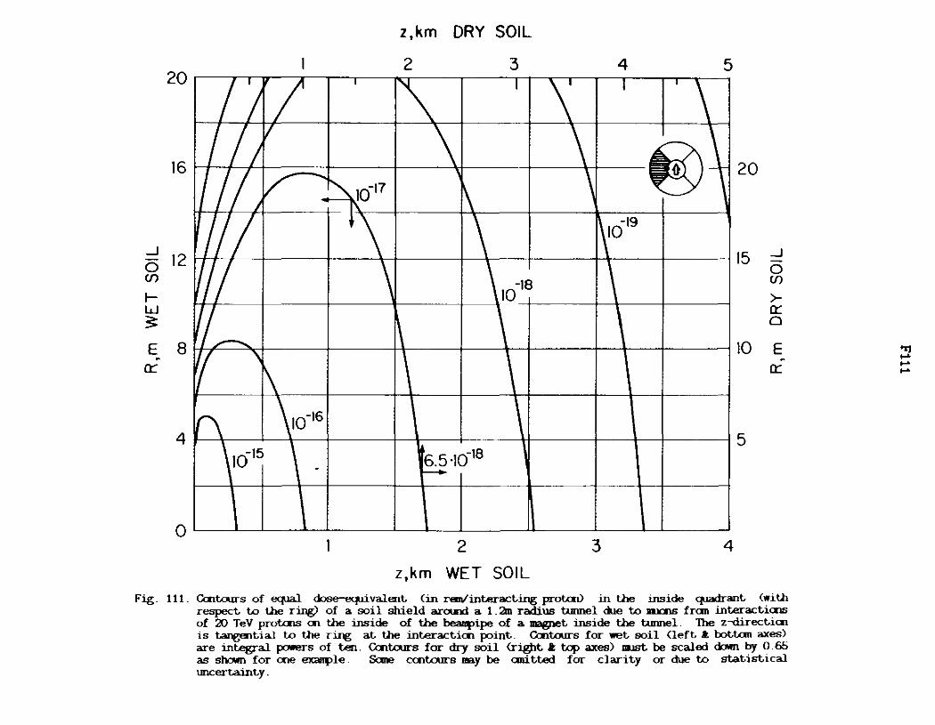
20
16
_J
0 12 Cf)
1-w ~
E. 8 0::
4
0
I
/ !1
I '/,
'/ I
I/ ' -----, .., j
(\ ' 10-15
'/ I
I
-~ 10-17 I'\ t\
\
\ \10-16
-
z,km DRY SOIL
2 3 4 5
~ I
\ I '\ 20 \ \ ~~-
\ ' 15 _J
0 \ 10-19
I
Cf)
>-\ 10-18 0:: 0
1
10 E . 0::
5 6.5·10-18 r---
2 3 4
z,km WET SOIL
Fig. 111. Cent.ours of eq..ia.1 dose-eq.rival.ent. (in rem/interacting protcn> in the inside cparlrant. (with respect. to the ring) of a soil shield around a 1 . 2m radius tunnel due to lll.ICllS fran int.eract.i<IW of 20 TeV protais en the inside of the beaupipe of a magnet. inside the tunnel. The z-tlirect.ic:n is tangential to the ring at. the int.eract.ic:n point.. Cent.ours for wet. soil Cleft. .t bot.tan axes) are integral pc:M'!!TS of ten. Centaurs for dry soil Crif)lt. .t top axes) JD.JSt be scaled <kMn by 0. 65 as shown for c:ne exanple. Sane centaurs nay be anit.t.ed for clarity or due to statistical llllCert.aint.y .
.., ... ... ...

_J
0 (f)
I-w 3
~
-0 u -
CL> c
E u >:
CL> (.'.)
F112
Z, km DRY SOIL
0 2 3 4
10 -3 10-3
10- 4 ~ 20 TeV
10-5 10 TeV 5 TeV
166
10-7
0 2 3 4
z ,km WET SOIL
Fig. 112. Radially integrated energy density (in GeV/an•interacting proton) in the inside cpadrant (with respect to the ring) of a soil shield arourui a 1. 2m radius tunnel due to nruans fran interactions of 5, 10 and 20 TeV protons an the inside of the beaDFipe of a continuous dipole inside the tunnel. The zdirectian is tangential to the ring at the interaction point. For wet soil use left .t; bot tan axes and for dry soil right .t: top axes .
10-4
10-5
10-6
10-7
_j
0 (f)
>-a::: 0
~ -0 u -
CL> c
E u
....... >
CL> (.'.)

_J
0 (./)
f-w 3:
-0 u -<ll c
E u
> <ll <.?
F113
R,m DRY SOIL
5 10 15 20
10-1 10-1
~ 10-2
TeV 10-2
10 TeV 5 TeV
10-3 10-3
10-4 10-4
5 10 15 20 TUNNEL
WALL R,m WET SOIL (Z=Ol
Fig. 113. Laigitudina.l.ly integrated energy density (in GeV/an•interacting protal) in the inside quadrant (with respect to the ring) of a soil shield around a 1 . 2m radius turmel due to llllJOilS fran interactions of 5, 10 and 20 TeV protons on the inside of the beampipe of a ccnt:inuous dipole inside the tunnel. The R-directian is perpendicular to a tangent to the ring at the interaction point. For wet soil use left .t; bottan axes and for dry soil right .t; top axes.
_J
0 (./)
>-a:: 0
~
0 u -<ll c . E u
> <ll <.?

z,km DRY SOIL
20 4 5 2 3
16 r--~---t,,,e:--~-t-~-=::......i-~~t--~---J~~-+~-~ 20
_J 12 15 _J
0 0 (/) (/)
I- >-w a:: ~ 0
I'" I ""' I 110 E ~ 8 VT"'1 __ -17 I ""1 . ,,....-18 a::
4 r---\---t~~---r~~-+-~~+-_,,_._----1f-----''t--t~~--+-'\-------l 5
0'--~--"~~-'--'~~-'--~'---'-~~-"--~~-'--1~---'-~---'-~
2 3 4
z,km WET SOIL Fig 114. Cent.ours of <qW dose-ecprivalent (in rem/interacting prot.aV in the tq>lbottan quadrant (with
respect to the ring) of a soil shield around a 1 . 2m radius tunnel due to nuans from interactiais of 20 TeV protais en the inside of the beaiiFipe of a magnet inside the tunnel. The z-rlirect1cn is tangential to the ring at the interacticn point. Cent.ours for -t soil <left .t bot.tan axes) are integral powers of ten. Cent.ours for dry soil <r~t I; tq> axes) DUSt be scaled dOlm by 0.6.5 as sl>'.Mll for cne exanple. Sane ccntours may be CJDitted for clarity or due to statistical uncertainty.
"1 .... .... ~
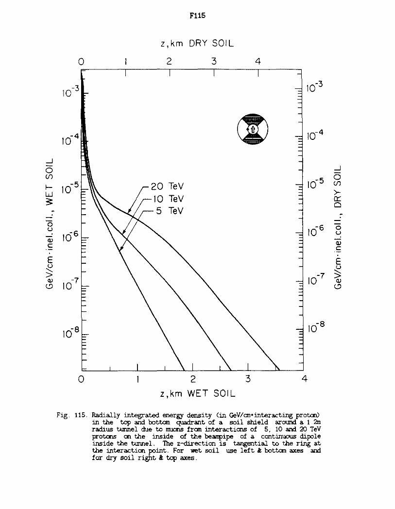
_J
0 (f)
I-w 3
-0 u -CV c
E u ;:;; CV
(.!)
F115
z, km DRY SOIL
0 2 3 4
10-3 10-3
10-4 ~ 10-4
10-5 20 TeV 10-5
10 TeV 5 TeV
166 166
10-7 10-7
0 2 3 4
z,km WET SOIL
Fig. 115. Radially integrated energy density (in GeV/an•interacting proton) in the top and bottan quadrant of a. soil shield a.round a. 1 . :dn radius tunnel due to moons fran interactions of 5, 10 and 20 TeV protons an the inside of the be31JFipe of a. continuous dipole inside the tunnel. The z-direction is tangential to the ring a.t the interaction point. For wet soil use left i; bottan axes and for dry soil right i; top axes.
_J
0 (f)
>-a:: 0
--0 u -CV c
E u :;:; CV
(.!)

__J
0 Cf)
f-w 3 --0 u -(l) c:
E u
> (l)
<.?
F116
R,m DRY SOIL
5 10 15 20
10-1 10-1
~ -2
10 10-2
10-3 10-3
20 TeV 10 TeV
-4 10
10-4
0 5 10 15 20
Fig.
TUNNEL WALL (Z =0)
R,m WET SOIL
116. Longitudina.lly integrated energ;J density (in GeV/on•interacting proton) in the top and bott.an quadrant of a. soil shield a.round a. 1. 2m radius tunnel due to muons fran interactions of 5, 10 and 20 TeV protons on the inside of the beanpipe of a. continuous dipole inside the tunnel. The R-direction is perpendicular to a. tangent to the ring a.t the interaction point. For wet soil use left & bottan axes and for dry soil right & top axes.
__J
0 Cf)
>-a::: 0 --0 u -(l)
c: . E u
....... > (l)
<.?
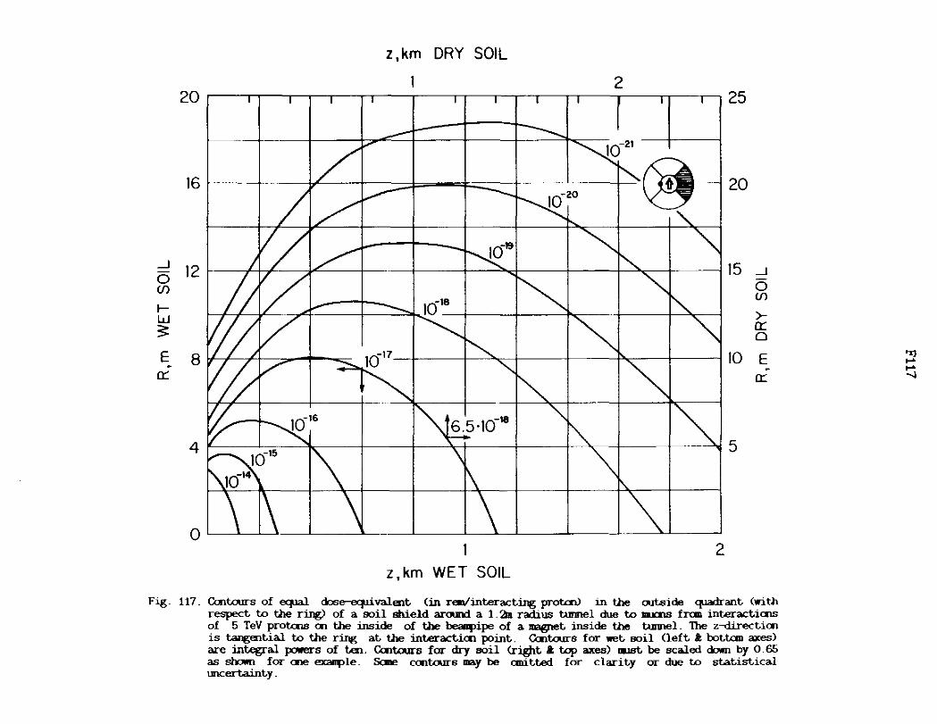
z, km DRY SOIL
2 20~~~~~~~~~~~~~~~~~~~~~~ 25
16 I I }" I --- I I .__ I ~- I "@ 20
_J 12 15
0 _J
Cf) 0
1018 If)
I- >-w 5: a::
0
E . 8 10 E . a:: a::
4 I' I ·- 5
OL____.__..L---1~~~__.__~_.___~-L-___.__._~~~~~~~~
2 z, km WET SOIL
Fig. 117. Centaurs of eq.ia.l dose-eq.rivalent. (in r<m/int.eract.ing prot£nl in the out.side q.iadrant. (with respect. t.o the ring) of a soil shield around a 1 . 2ln radius tunnel due t.o llllCilS fran int.eract.iros of 5 TeV prot.ros oo the inside of the beaq>ipe of a magnet. inside the tunnel. The z-direct.icn is tangential t.o the ring at. the interact.ioo point.. Centaurs for wet. soil Cleft. ll; bot.tan axes) are integral powers of ten. Cent.ours for dry soil Cr~t. ll; t.op axes) lllJBt. be scaled down by 0.65 as shown for ooe exanple. Sane coot.ours may be cmit.t.ed for clarity or due t.o st.at.ist.ical uncertainty.
"1 .... .... --.:i

z ,km DRY SOIL
2 3 20 25
161 I I/ ~ 20
_J 12 15 _J
0 0 Cf) Cf)
I- >-w n::: ~ '"-18 0
8 r I I I 4617 I\ I l I 110 E E \ \ -- II n::: n:::
4 I '< __ l I '. ---+-~-+~~+--t-~~+-i5
OL-->.--'L__--'--'--~--'~--'L__--'--~-A.----'-~~-'-~~~-U
2 3
z,km WET SOIL
Fig. 118. Caltaurs of equal dose-eq.ri valent (in rem/interacting protcnl in the aitside cpia<trant (with respect to the ring) of a soil shield around a L2m radius tunnel due to llllalB fran interacti<IIB of 10 TeV protals on the inside of the beanpipe of a magnet inside the tunnel . 1he z-direction is tangential to the ring at the interactirn point. Centaurs for wet soil (left .t bottcm axes) are integral powers of ten. Cent.airs for dry soil <right .t tq> axes) lllJSt be scaled down by 0. 66 as shown for crie exanple. Saoo centaurs may be emitted for clarity or due to statistical tmcertainty.
~ .... CD

z,km ORY SOIL
w 2 3 4 5
1619 rQ
16 I ! f 11 I I I \ I I \ V!:!/ 20
__J
0 12 15 __J
Cf) 0 Cf)
I- >-w ~
a:: 0
E 8 E 10 -a:: a::
4 r---+--+~~---t--'.--~t--~-+'t--~-+-~-+-+-~-------~~~5
0 2 3 4
z, km WET SOIL Fig. 119. Caitours of equal dose-eq.rivalent. (in ren/int.eract.ing prot.aJ) in the out.side q.iadrant. (with
respect. t.o the ring) of a soil shield around a 1 . 2ln radius t.unnel due t.o DU:llS fran int.eract.iais of 20 TeV prot.a>s en the inside of the beaq>ipe of a magnet. inside the t.unnel. The z-direct.icn is tangent.ial t.o the ring at. the int.eract.icn point.. Caitours for wet. soil Cleft. .t: bot.tan axes) are integral powers of t.en. Cait.ours for dry soil Cr:ifPt. .I; tcp axes) 111.JSt. be scaled down by 0.65 as shown for cne exanple. Sane coo.tours nay be rnrit.t.ed for clarit.y or due t.o st.at.ist.ical uncert.aint.y.
.... .... .... co

_J
0 (/)
I-w $:
-0 u -<I) c ·-E u ..._,__
> <I)
(.?
F120
z, km DRY SOIL
0 2 3 4
10-3 10-3
10-4 @ 10- 4
20 TeV
165 10-5
1Cl6 10-6
10-7 10-7
2 3 4
z ,km WET SOIL
Fig. 120. Radially integrated energy density < in GeV/an•interacting proton) in the outside quadrant (with respect to the ring) of a soil shield axOlllld a 1 . 2m radius tunnel due to muons fran interactions of 5, 10 and 20 TeV protons en the inside of the beanpipe of a continuous dipole inside the tunnel. The zdirecticn is tangential to the ring at the interaction point. For wet soil use left t bottan axes and for dry soil right t top axes.
_J
0 (/)
>-a:: 0
-0 u -<I) c ·-E u ..._,__
> <I)
(.?

_J
0 (/)
I-w 3: -0 u -Q) c:
E u
' > Q)
(!)
F121
R,m DRY SOIL
5 10 15 20
10-1 10-1
20 TeV @ 10 TeV
10-2 5 TeV 10-2
10-3 10-3
10-4 10- 4
0 TUNNEL
5 10
R,m WET SOIL
15 20
Fig.
WALL (Z =O)
121. Longitudinally integrated energy density (in GeV/an•interacting proton) in the out.side quadrant (with respect to the ring) of a soil shield arOlllld a 1. 2m radius tunnel due to muons fran interacticms of 5, 10 and 20 TeV protons en the inside of the beanpipe of a ccntinuous dipole inside the tunnel. The R-direction is perpeOOicular to a tangent to the ring at the interaction point. For \let soil use left .t: bottan axes and for dry soil right .t: top axes.
_J
0 (/)
>-a::: 0
-0 u -Q) c:
E u ' > Q)
(!)

20
16
_J 12 0 CJ)
f-w 3 E 8
Cl:'.
4
'//I' (/I I I
-
/ ' r1 ........:
I '
'/ \ I
ICJ16
0-15
i l
0
-
I
-
10-17
; -
6.5·10-18 L......
l
z,km DRY SOIL
2 ' \ I
10-19
-ICJ1s
z, km WET SOIL
3
\f T '
ICJ20 €)
I I
2
25
- 20
- 15 _J
0 CJ)
>-Cl:'. 0
10 E . Cl:'.
- 5
l
3
Fig. 122. Ccntours of eq.iaJ. dose-equivalent (in rem/interacting protoo) in the inside cpadrant <with respect t.o the ring) of a soil shield aroud a 1 . 2m radius tunnel due t.o lllxnB fran interacti<IlS of 5 TeV protoos en the outside of the beanpipe of a magnet inside the tunnel. The z-directiai is tangential to the ring at the interacticn point. Ccntairs for wet soil <left a: bottan axes) are integral pc:>ll'!!!l'S of ten. Ccntours far dry soil <right At tcp axes) lllJBt be scaled down by 0.66 as shewn far one exanple. &me cent.ours m.y be emitted far clarity ar due to statistical w>eertainty.
'"%] .... 1:3

20
16
_J
0 12 (f)
1-w 3:
E . 8 a::
4
z ,km DRY SOIL
2 3 4 5 25 l!r '/ ' ' I
1
\ I T I/// '. T' l '\ ~
10~1 - 1017 g -II I ' 'I 10_,9
(/ \ 10-~ I ~ 6.5·10-18
"""' 10-16 --rr---t-W-~ ~ 161410 15
~
• I I I I I I
0 2 3 4
z ,km WET SOIL
20
15
10
5
_J
0 (f)
>a:: 0
E a::
Fig. 123. Cent.ours of equal dose-equivalent (in ran/interacting prot.cn) in the inside q.iadrant (with respect to the ring) of a soil shield aroud a I. 2rn radius tunnel due to lllJalS fran interact1C11S of 20 TeV protCl'lS on the outside of the beanpipe of a magnet inside the tunnel. The z-directico is ~tial to the Ting at the interaction point. Cent.ours for wet soil <left. I. bottan axes) are integral powers of ten. Cent.ours for dry soil <rj@t I. top axes) llllSt be scaled OOim by 0.65 as shown for coe ex31IJ'le. &me ccotours DBy be anitted for clarity or due to statistical tmcertainty.
"1 ... ~

0 2 3 4
z,km WET SOIL
Fig. 124. Radially integrated energy density <in GeV/an•intera.ct:ing protal) in the inside quadrant (with respect to the ring) of a soil shield arouru:i a 1. 2m radius tunnel due to muons fran interactions of 5, 10 and 20 TeY protons an the outside of the 'beaiqlipe of a continuous dipole inside the tunnel. The zdirection is tangential to the ring at the interaction point. For wet soil use left .t. bottan axes and for dry soil right .t. top axes.

_J
0 (f)
I-w ~ -0 u -Q) c: ·-E u ::;; Q)
(.'.)
F125
R,m DRY SOIL
5 10 15 20
10_, 10-1
20 TeV €0 10 TeV
10-2 5 TeV 10-2
10-3 10-3
-4 10
10-4
Fig.
TUNNEL WALL (Z=O)
5 10
R,m WET SOIL
15 20
125. Loogitudina.lly integrated energy density (in GeV/an•interacting proton) in the inside quadrant (with respect to the ring) of a. soil shield a.roun:i a. 1 . 2m radius turmel due to lillCllS fran interactions of 5, 10 and 20 TeV protons an the outside of the beanpipe of a. continuous dipole inside the tunnel. The R-directicn is perpendicular to a. tangent to the ring a.t the interaction point.. For wet. soil use left & bottan axes and for dry soil right & top axes.
_J
0 (f)
>-0::: 0
-0 u -Q)
c: ·-E u
....... > Q)
(.'.)

_J
0 (/)
I-w s: -
0 u -Q) c:
E u
> Q)
(..!)
F126
z ,km DRY SOIL
0 2 3 4
10-3 10-3
10-4 @ 10-4
10- 5 10 5
20 TeV 10 TeV 5 TeV
10-6 166
10-7 10-7
\ \ 10-8
168 \ \
0 2 3 4
z,km WET SOIL
Fig. 126. Radially integrated energy density ( in GeV/an•intera.cting proton) in the outside quadrant (with respect to the ring) of a soil shield around a 1. 2m radius tunnel due to muons fran interactions of 5, 10 and 20 TeV protons an the outside of the bea!!i>ipe of a continuous dipole inside the tunnel. The zdirectian is tangentia.1 to the ring at the interaction point. For wet soil use left .t bottan axes and for dry soil right .t top axes
_J
0 (f)
>-a:: 0
-0 u . -Q) c: ·-. E
~ Q)
(..!)

_J
0 (/)
I-w 3 -0 u -<V c
E u
> <V (..'.)
FlZ7
R,m DRY SOIL
5 10 15 20
10-1 10-I
20 TeV @ 10 TeV
10-2 10-2
10-3 10-3
10-4 10-4
0 5 10 15 20
Fig.
TUNNEL WALL ( Z= 0)
R,m WET SOIL
127. Longitudinally integrated energy density (in GeV/an•interacting proton) in the outside quadrant (with respect to the ring) of a a soil shield around a 1 . 2m radius tunnel due to nu:ins fran interactions of 5, 10 and 20 TeV protons an the outside of the be31l¥>ipe of a continuous dipole inside the tunnel. The R-direcian is perpendicular to a tangent to the ring at the interaction point. For wet soil use left i bottan axes and for dry soil right i top axes.
_J
0 (/)
>-a:: 0
-0 u -<V c ·-. E u
....... > <V
(..'.)

20
16
_J 12 0 Cf)
1-w =i:
E 8 a:
4
0
z ,km DRY SOIL
I/// 1 '\ I
\
)// / \ 'I '
I I ~
/ """ 'II - 10-17
' 11 / ' 'fir\ II \ 10-16 - 6.5·10-18
10-15
z ,km WET SOIL
2 I '\ I I 25
\~- 20
1019 -
15 _J
0 10-18 Cf)
>-a: 0
10 E a::
5
2
Fig. 128. Catt.ours of ~ dose-eq.llvalent (in rmi/interacting protal) in the inside CJl"':lrant (with respect to the ring) of a soil shield acoud a 1. 2m radius tunnel due to llll006 fran interacti<IlB of 5 TeV prot<IlS in the middle of the beanpipe of a magnet inside the tunnel. The z-directicn is tangential to the ring at the interacticn point. Cent.ours for wet soil <left I: bot.tan axes) are integral J>Ol"'l"S of ten. Catt.ours for dry soil <right I: top axes> DaJSt be scaled dcMrl by 0. 6.5 as shown for cne exallJ>le. Sane cent.ours DBy be anitted for clarity or due to statistical uncertainty.
"rJ .... ~

z,km DRY SOIL
0 20
2 3 4
/f/I 1 I 1 \ I 1
\
0
5 25
16
_J 12 0 Cf)
1-w ~
E 8 0::
4
0
20
15
/1 --. I 1
//)/ \ ~-l// - 16
17 ~ -If r\ 10-~ I ' 16~ ' -+---+--~
10 I/
-
5
r=----l----l 1616 -15 --r-t~-=---t-t---t---tL--
l01 IO 6.5 · I0-18
h t--
2 3 4
z ,km WET SOIL
_J
0 Cf)
>-0:: 0
E -0::
Fig. 129. Contours of ~ dose-ecprivalent (in r€111/interacting protaJ) in the inside quadrant <with respect t,o the ring) of a soil shield aroud a 1 . 2m radius tunnel due w lllJCllS fran interacti<IJS of 20 TeV prot-<IJS in the middle of the beanpipe of a magnet inside the tunnel. The z--direcbai is tangential to the ring at the interactiai point. Contours for wet soil <left It bottcm axes> are integral powers of ten Contours for dry soil <right .t. tq> axes) DJ.JSt be scaled dollm by 0 .6.5 as shoim for aie exaDJ>le. &:me cC11tours nay be anitted for clarity or due w statistical tmcertainty.
"1 ,_. t8

_j -0 (,/)
f-w 3
-0 u -Cl) c:
E u
:> Cl)
<.:::>
F130
z, km DRY SOIL
0 2 3 4
10-3 10-3
10- 4 20 TeV ~ 10-4
TeV TeV
10-5 10-5
166 10-6
10-7 10-7
0 2 3 4
z,km WET SOIL
Fig. 130. Radially integrated energy densit.y < in GeV/cm•interact.ing proton) in the inside quadrant (with respect to the ring) of a soil shield around a 1. 2m radius t.urmel due to llllClllS fran interactions of 5, 10 and 20 TeV protons in the middle of the beallJlipe of a continuous dipole inside the t.urmel. The zdirecticn is tangent.ial to the ring at. the interaction point. For wet soil use left i; bottan axes and for dry soil right i; top axes.
_j
0 (,/)
>-et: 0 ~
0 u -Cl) c:
E u
:> Cl)
<.:::>

_J
0 (/)
I-w 3
-0 u -<V c
E u
> <V
<.::>
F131
R,m DRY SOIL
5 10 15 20
10-1 10-1
20 TeV ~
10-2 10-2 10 TeV
5 TeV
10-3 10-3
10-4 10-4
0 5 10 15 20
TUNNEL R,m WET SOIL WALL (Z=O)
Fig. 131. Longitudinally integrated energy density (in GeV/an•interacting proton) in the inside quadrant <with respect to the ring) of a soil shield a.round a. 1.2m radius turmel due to llllClllS fran intera.cticns of 5, 10 and 20 TeV protons en the middle of the bea11f>ipe of a. continuous dipole inside the turmel . The R-di.recioo is perpendicular to a tangent to the ring a.t the interaction point. For wet soil use left i. bottan axes and for dry soil right i. top axes.
_J
0 (/)
>-0:: 0 --
0 u -<V c
E u
> <V
<.::>

20
16
_J
0 12 (f)
f-w $:
E_ 8 0::
4
z,km DRY SOIL
2
)I/~ I I ~ I
; fr--- - . . _ _ __ __ · · ""' , I I / ---- -- -----t-~ "-_J
I/)/ ~ \ f / / ~ \ t
'/ " ' I 1617 \ -
/ ' 1\' 16~ \ 10"" ---'
(\ \ 10"16 • 6.5 -10·1• -
10'410·15
2 z,km WET SOIL
25
20
15 _J 0 (f)
>-0:: 0
10 E 0::
5
Fig. 132. Ccntou:rs of equal dose-equ:i valent. <m rem/interacting protai> in the outside quadrant. <with respect. to the ring) of a soil shield around a 1 . 2ln radius tunnel due to llllOnS frcm interacti<IlS of 20 TeV protons in the middle of the beanpipe of a magnet inside the tunnel. The z-direct.i<n is tangential to the ring at U.e interact.icn point. Ccntou:rs for wet soil <left & bot.tan axes) are integral powers of ten. Ccntou:rs for dry soil <right & t.q> axes) nust be scaled down by 0. 65 as shown for <Ile exarJ{lle. Scme ccnta.rrs may be emitted for clarity or due to stalisLical uncertainty.
"] .... k5

s,ft WET SOIL
0 200 400 600 800 1000 1200
30
St------:~~~---P~~+-~-+~~--t-~~+-~ ~ _J b
20 _J
0 0 U) U)
I-I- w w ~
~
-~ -.~15 1' K f; K "'HT .._
I -n::
10
T~~~~L., " I ?t 1- I ...... I ...... I '- I " I
0 '---~~~~____,__~~---'-~~~~~~~~~~~~~ 0 100 200 300 400
s,m WET SOIL
Fig. 133. Coo.tours of ~ dose-ecpivalent. (in nn/int.eract.ing protai) in the inside q.iadrant <with respect. to the ring) of a soil shield around a I. 2m radius tunnel due to IJIJOOB fran int.eractiais of 5 TeV protais an UJ.e. inside of the beanpipe of a magiiet inside the tunnel. The abcissa, s. is the dist.ance aloog the ring fran the int.eract.icn point.. Sane cent.ours oay be anitt.ed for clarity or due to statistical uncertainty.
.... .... ~

s,ft WET SOIL
500 1000 10 1500
- 30 ---+-----;---,
81 / V I I '-.,. --'ol-------t--~
_j 20 _J
0 6 0 en en I- I-w w 3 3
~4rq~ ~ I\ ~r\ l\ 1\ I ~ -. 0::
.~-14
10 ko13\l I ""J "{ ~ \I \I\ I 2
TUNNEL WALL
0 100 200 300 400 500
s,m WET SOIL
Fig. 134. O:ntours of eq.ia.1 dose-eq.ri valent (in r<•nlinteracting protcnl in the inside quadrant (with respect to the ring) of a soil shield around a 1. 2m radius tunnel due to 111JOOS frao interacti<IJS of 10 TeV prot<IJS en the inside of the beanpipe of a ""'f}l"t inside the tunnel. The abcissa. s. is the distance aloog the ring frcm the interacticn point. Sane caitours may be anitted far clarity or due to statistical wcertainty.
'"rj .... ~

s, ft WET SOIL
1000 2000 10.--.-x~~-.~~"<lr~~-y;----r~.-~-..-~-.-~---,-.,
I I I A .... ~.... I '\. I \. I\. I I =i 30
8 1 ,, , 4 I ri. I\ \I " 10-20 _~ 11r , ~ ' ' 4- ~
6 20 __J
__J 0 0 Cf)
Cf)
I- I-w w ~ ~ 4 -E .._ - -n:: 10 n::
21----'\-------'oj-~~-+-~-"''k--~-+~-----'-..+-~~~~-+~~~
TUNNEL fl88Si'j?Rll! \. I "' I I >t I "' I "' I "-.. I WALL
0 200 400 600 800
s,m WET SOIL
Fig. 135. O:ntours of <qiaI dose-ecp..tivalent (in ren/interacting protal> in the inside ~ant (with respect to the ring) of a soil shield around a 1 . 218 radius tunnel due to 111.QlS fran interacticns of 20 TeV protals en the inside of the beanpipe of a magnet inside the tunnel. lhe abcissa. s. is the distance alcng the ring fran the interacti<Il point. Sane centaurs may be anitted for clarity or due to statistical w..certainty.
'Z) .... 81

_J
0 (/)
I-w :s: -0 u -CL> c ·-
E u
~ CL>
(.!)
F136
s,km DRY SOIL
0 0.2 0.4 0.6 0.8 1.0
10-3
~ 10-3
20 TeV 10 TeV
10-4 10-4
10- 5 10-5
10- 6 10-6
10-7 10-7
0 0.2 0.4 0.6 0.8
s,km WET SOIL
Fig. 136. Radially integrated energy density ( in GeV/an•interacting proton) in the inside quadrant (with respect to the ring) of a soil shield around a 1.2rn radius tunnel due to IDlClllS fran interactions of 5, 10 and 20 TeY protons an the inside of the beal!Jlipe of a continuous dipole inside the tunnel. The abcissa, s, is the distance along the ring fran the interaction point. For wet soil use left I; bottan axes and for dry soil right I: top axes.
_J
0 (f)
>-a:: a . 0 u
-CL> c
E u
....... >
CL> <.:)

......J
0 (f)
I-w 3:
~
0 u -Q)
c
E u "-> Q)
(..'.)
10-1
10-2
10-3
10-4
0 2
2 TUNNEL
WALL
F137
R ,m DRY SOIL
4 6 8 10 12
10-1
€) 10-2
20 TeV 10 TeV
10-3
10- 4
4 6 8 10
R ,m WET SOIL
Fig. 137. Longitudinally integrated energ density (in GeV/an•interacting proton) in the inside quadrant (with respect to the ring) of a soil shield around a 1. 2m radius tunnel due to rmJCl!lS fran interactions of 5, 10 and 20 TeV protons on the inside of the belll!Jlipe of a continuous dipole inside the tunnel. The abcissa, R, is the radial coordinate of the tunnel. For wet soil use left I: bottan axes and for dry soil right I: top axes .
......J
0 (f)
r-a:: a . -
0 u -Q) (:;
E u "-> Q)
l!)

s,ft WET SOIL
500 1000 1500 10
I I I I I I I I I 30
I I
8 €0 _J _J
g 6 20 0 (/)
I- I-w w 5: !:
E --ci 4 -a::
10
ri:~~L 9 ' 'I ' I ' I ' I 'l I " I I
0 100 200 300 400 500 s,ft WET SOIL
Fig. 138. Caitours of equal dose-equivalent (in ran/interacting prntaU in the inside q.iadrant (with respect to the ring) of a soil shield around a 1. 2m radius tunnel due to OIJall8 frCD1 interactiCDS of 5 TeV prot<DS en the outside of the beanpipe of a magnet inside the twmel. The abcissa. s. is the distance aloog the ring frCDI the interactic:n point. Sane cc:ntours may be CDlitted for clarity or due to statistical uncertainty.
.., .... ~

_J u
0 Cf)
t-w ~
~~I I
s, ft WET SOIL
1000
1,-\15
"'' I '\I
2000
30
~ 20
_J
0 Cf)
t-w ~
'\I "'I ""'I ,0 ;
T':~~L ..,.., '. ' I " I I I ' I I' F' I
0 200 400 600 800 s,m WET SOIL
Fig. 139. Centaurs of eq.ial dose-eq.rivalent (in rem/interact~ protcn> in the inside quadrant (with respect to the ring) of a soil shield around a 1 . an radius tunnel due to lllJalB fran interact1oos of 20 TeV protoos en the outside of the beanJ>ipe of a magnet inside the tunnel. 1he abcissa. s. is the distance aloog the r~ fran the interacticn point. Saue contours may be anitted for clarity or due to statistical uncertainty.
..,
..... !8

0
10-3
.....J 10-4 0 <J)
f-w 3
- 10-5 0 u -<V c::
E 10-6 u :> <V
(.'.)
10-7
0
Fig. 140.
F140
s, km DRY SOIL
0.2 0.4 0.6 0.8 1.0
~ 10-3
20 TeV
10-4
10-5
10-6
10-7
0.2 0.4 0.6 0.8
s,km WET SOIL
Radially integrated energy density < in GeV/an•interacting proton) in the inside quadrant (with respect to the ring) of a soil shield around a 1. 2m radius tunnel clue to muons fran interactions of 5, 10 and 20 TeV protons an the outside of the bean;>ipe of a continuous' dipole inside the tunnel. The abcissa, s. is the distance along the ring fran the interaction point. For wet soil use left .t bottan axes and for dry soil rigpt .t top axes.
.....J
0 <J)
>-a:: 0
-0 u -<V c:: ·-E u ' > Q)
(.'.)

_J -0 (j)
f-w 3
0 u -<L> c:
E u '-> <L>
<.!)
10-1
10-2
10-3
10-4
10-5
0
2
2 TUNNEL
WALL
F141
R ,m ORY SOIL
4 6 8 10 12
10-1
€) 10-2
20 TeV 10 TeV 5 TeV
10-3
10-4
10-5
4 6 8 10
R ,m WET SOIL
Fig. 141. Langitudina.lly integrated energy density (in GeV/an•int.eracting proton) in the inside quadrant (with respect to the ring) of a soil shield around a 1 . 2m radius tunnel due to lIDJOilS fran interactions of 5, 10 alld 20 TeV protons on the outside of the be311Fipe of a continuous dipole inside the tunnel. The abcissa, R, is the radial coord:ina.te of the tunnel. For wet soil use left i; bot.tan axes and for dry soil right i; top ax:es.
_J
0 (j)
>-a:: 0
-0 u -
<L> c:
E u '-> <L>
<.!)

-"
14 19 Region i Om ..
1
Side Wall
r
E (\j
E Back o Wall ~ Region
"'1 ------------------+-------------------~- ---- ....
j I A r ~
Fig. 142. Cross-section of collision hall as represented in program. For s:iJJJ>licity, the geanetry is assumed to be cylindrically syumet.ric about the beam direction.
~

z • ft WET SOIL
0 100 300 400 500
7rl7r 10-19
I 6
10-18 ...J _J -- 0 0 VJ (/) -17
- I-I- A w w 15 3: ~
10-16_
E --~ ~
_J 10-15 10 _J
_J J c( 4 3:: 3::
a:: a:: I 10-14 a:: a::
5 ' 'I. ' 11
'oi'3 10-12 .......
0 50 100 150
~
z, m WET SOIL BACK WALL
Fig 143. Cont..aurs of equal dose equivalent (jn rem/inelastic collision) in soil side wa.11 of collision hall, due to hadrons frCJD collidiJ ~ '""""" of 5 TeV each. A 1mn thick beanpipe is present. Sane contours may be CJDitted for clarity or due to statistical wicertamty.
'"r] .... f;j

Fig. 144. Caltours of equal dose equivalent (in ran/inelastic collisicn) in soil side wall of collisiC<l hall, due to hadrC<lS fran colliding beanE of 20 TeV each. A 1nm thick beanJ>ipe is present Sane cC<ltours may be anitted for clarity or due to statistical uncertainty.

....J
0 (/)
I-w ~
--0 (.J . -
Q) c • E (.J ~
....... (/)
0::: <l: I-(/)
F145
z I ft WET SOIL
0 100 200 300 400 500 600
20 TeV + 20 TeV
10-1 10-1
9 9 8 5 TeV + 5 TeV 8 7 7 6 6 5 5
4 4
3 3
2 2
10-2 10-2 9 9 8 8 7 7 6 6
5 5
4 4
3 3
2 2
10-3~0_.___.__...__..__~__.__.__.___..__...__..__....____.__.._...,,._,,_...~~~ 50 100 150
Fig.
z, m WET SOIL
145. Radially int.egr"ated star density (in sta.rs/cm•inelastic collisioo) in side-wall of collisicn hall (see fig. 142) for colid:ing beams of 5, 10 and 20 TeV protals interacting at ~The calculaticn has a cut-off m::menU!m of 0.3 GeV/c.

_J
0 (f)
I-LL.I 3:
~
-0 0
-QI c:
E 0 ~
...... (f)
c:: <{ I-(f)
F14B
R - RwALL , m DRY SOIL
0 2 3 4 5 6 7 8 9
10 1
10° 10°
10- 1 10·1
10- 2 10· 2
10- 3 10·3
10· 4 10· 4
10·5 10· 5
0 2 3 4 5 6 7
R- RwALL , m WET SOIL
Fig. 146. Longitudinally integrated star density Cin st.ars/an•inelastic collisicru lll side-wall of collision hall (see fig. 142) for collidillg beams of 5, 10 and 20 TeV protons interacting at ~. The calculation ha.s a cut-off JIOllE!Iltum of 0.3 GeV/c. For wet soil use left i; bottan axes and for dry soil right .i: top axes.
_J -0 (f)
>-c:: Cl
~
-0 0
-QI c:
E 0 ~
...... (f)
c:: <{ I-(f)

z,ft. WET SOIL
0 5 SI DE 101 I I 'I I [
WALL ll!!Q ... ~ -+- <::: I I "j., I "1, I \. I \JIU·- =130
8 ~--+~~-i.-·-~---~T--~
25 7~·--+- ~-+-~·---t---'<~-+-~---t-
_J
0 en ...J
0 (f)
61> ..L t--- -----"I. . - I '\ I I "- --i 20 1-
..... w s----+-----+---+---~
W 3:
~ 15 .::
E
...J w z z ::> l-
a:: I
ct:
4t-----+----+-
3t----+-------jf-- ---l-110
21----t---+---+---"~--+----P...c----t---t---"....t--~
10-10 5
0 0 0 I 2 3 4 5 6 7 8 9 10
z, m WET SOIL
-' w z z ::> l-
a:: I
a::
Fig. 147. Ccrttcm-s of equal dose equivalent, (in rem/inelastic collisicn) in soil back wall of collisim hall. due to hadr<IJS fran colliding beams of 5 TeV each. A 1mn Urick beanpipe is present. Sane ccntcm-s may be anit,ted for clarity or due to statistical uncertainty.
'Tl ~
~

10 0
SIDE WA ,LL
_J
0 CJ)
tw ~
E
...J w z z ::> l-
a:: I
a::
8
7
6
5
4
3
2
I --0
0
z, ft. WET SOIL
5 10 15 20 25 30
30
25 _J -0 CJ)
20t-w ~
' ' I ' . '
K "'-, I , . , I , ~ , \ I , '·
---"'
!'-. 10-16 -
""\ \ '~0-1• ,\ _
~ . "{0-14 \ ~
~ \
\ .. '~0-13 \ · ~ .
' \ \ 10-12 \ \ ~
. 15 ~
~ \ \ \ "' . ~ -
...J w z
10 z :::> I-
a:: I
5 a::
'Z°-11 \ '\ ~ \ '""' ~: 10-10 "" ' ~ .
-t-.... !-o... ~r-- -= . " ~
........_L... ~ . ~
2 3 4 5 6 7 8 9 0
10
z, m WET SOIL
Fig. 148. Cent.ours of equal dose equivalent <in rem/inelastic collisicn) :in soil back wall of collisi<D ha11. due to hadrons frooi colliding beams of 20 TeV each. A 1mn thick beanpipe is present.. Sane C<Dtours may be ani t.ted for clari t.y or due to statistical. uncert.amt.y
"I ..... $

0
....I -0
"' ,_ UJ 3:
--0
10° u
-Q> c • E u -......
I,/)
a: <( ,_ "'
0
Fi&.
F149
z, m DRY SOIL
2 3 4 5 6 7 8 9 10 II 12
5 TeV + 5 TeV
10°
2 4 5 6 7 8 9 10
z,m WET SOIL
149. Radially integrated star d!mit.y <in stara/C11•i.Ilelallt.ic colliaiai> in 6eck-All of collisiai hall Csee fi&. 142> far collidiJlg be.- of 5, 10 and ::K> TeV protaJs in~ at. ~- 'Ibe c&l.c:ulat.iai hall a c:ut.-Qff llDIBltua of 0.3 Geil/c. For wt. BOil un left t bot.tan - and for dry BOil right. t top-.
....I -0
"' >-a: 0
--0 u
-Q> c • E u -......
I,/)
a: <( ,_ I,/)

...J -0 en I-w ~
...... -0 (,)
-Q) c
E (,) -' en a:: < I-en
0 2
10·1
0
F150
R - RruNNEL , m DRY SOIL
3 4 5 6
2 3 4 5
R - RruNNEL , m
7 8 9 10 II 12
6 7
WET SOIL
a 9
10 1
10°
10·1
10
Fig. 150. Lcqitud:lnally integrated star dmsity <in stars/Qll•inel.ast:i.c colli.aial> in ~ of colli•\m b&ll ~~142> far colli~ be.- of S. 10 -1 3l TeV protalll in at ~. The c:&lci1Jaticm bu a cut.-off iilLJBltUIR of 0.3 GeV/c. Far wt eoil UN left a bot.tail aD9 -1 far dry eoil right a Ulp - .
...J
0 en
>-a:: Cl
...... -0 (,)
-Q) c • E " -' en a:: < I-en

z, ft WET SOIL 0 100 200 300 400 500 600 - - -
7
6
.....J 5 0 (/)
t- 4 w ::= E 3 -a::
2
.,..__
10-18
10-17 -
==i-t~±-+4,o-~16 r
10-11 16'" --
20
_J -0
15 (/)
1--w ::=
10 --. a::
5
0 0 50 100 150
0 200
Fir, 1!>1
z, m WET SOIL
(A::I1lA.JUf5 o[ e<p..aa.I dose e<p11va.lent.. (ill rem/1n~last.1c co)) 1s1Ul.) in H<>l I h,1r·r1A091.1Hig d l.JedlllHJ~. due to hi:w:b-c:ns fran coll1d1ng bealR9 of & TeV ea.ch &:wne ca.taJrs may re rnut.t.eJ for (:Id.I 1Ly 01· dHt~ 1 .. , ~:1.at.1st.1c·a.l lD1cert..unt.y
'Tl .... U1 ....

z I ft WET SOIL
0 100 200 300 400 500 600 I
7._ -~ -r ~ " - -r
., -- 1---_ 10"
18
'
~~===t==t-------=1~==~~~--=-1 i-:.=..--L • - -· -17 r--- 1
-r-- -~ -" ,____ ' r-.... 1c>l6 .
7
6 20
5 ..J ..J
0 r-t-::::::::=t--J=--_L r-:::--1-.__ -: " =~· . .... - ' f--- ---4--_d
15 -0 (/) 4
'--- 10·14 1--- . 1-
j t---- t--' o"" -'---. 10
w 3:
E 3
- ''- t---1......... ·r---t--J11co·12 I -- L......._ - . f---- ' 0: 2
0 0
10·11
10·1• -f--_ ' '
5
• • 50 100
z, m WET SOIL
150 0
200
(/)
I-w 3:
---a:::
Fig 152. Cattours of <qJal dose "'flivalent. (in r..tinelast.ic colhsim) in soll surround;,..; a bea"'"P"· due lo hadr<flB fraa colhdi~ bean6 of 20 TeV each. &- c:aitours may be cmnt.ta:I for cla.r 11.y or- due lo st.at..ist.1cal uncert.a.J.nt..y
..,, .... U1 llJ

F153
z 'ft WET SOIL
0 100 200 300 400 500 600
9 9
8 8
7 7
6 6
5 5
....J 4 4 0 (/)
I-UJ ~
3 3
--0 u
2 2 -Cl> 5 TeV + 5 TeV c:
E u -....... (/)
a:: ct 10· 1 10·1 I-C/l 9 9
8 8
7 7
6 6
5 5
0 50 100 150 200
z, m WET SOIL
Fig 153. Radially integrated star density <in stars/cn•inelastic collisial) in soil SUIT~ a. ~ipe, far collidJ.ng beans of S, 10 and 20 TeV protais interacting at z:().
The ca.lcula.t.iai haa a cut~! m:mentum of 0.3 GeV/c.

...J -0 (/')
..... UJ :I:
-0 v
-GI c:
E u -' (/')
a: <{ ..... (/')
F154
R-RP,PE, m DRY SOIL
0 2 3 4 5 6 7 8 9
101 20 TeV + 20 TeV 101
10° 10°
5 TeV + 5 TeV
10-1 10·1
10·2 10·2
10"3 10"3
10·4 10"4
0 2 3 4 5 6 7
R-Rpipe x,m WET SOIL
Fig. 154. l.a!gitudlnally integr'a.tA9d star dl!lnsity (in sta.rs/an•ihelastic collisiCll) in 110il ~a. ~ipe. far colliding De.of 5, 10 and 20 TeV protaia interacting a.t z=O. The ca.lc:ulatiCll hu a. cut-off lllCllllllt\111 of 0. 3 GeV/c. Fae wet 110il use left a: bottan - and fac dry 110il right a: top axes.
...J -0 (/')
>-a: 0
--0 v -GI c: • E u -......
(/')
a: <{ ..... (/')

z, km DRY SOIL
2 3 4
12
s~\ \ I ~I I~ ~ in-221 I 111
:m .... I ~~ ~~ I 10-20
8 ...J 6 ·- -~- --' 10-19 -· - - ...J 0 7 -(/) 0
I- 5 (/)
6 >-w a:: ?: 4 - - - - - - 5 0
E 10-•1 E ~ 4 a:: 3 • a::
3 II \ '- '
_, .. ' ..... ' .... ' ' ' ' " . ' 2
" . ·~ ' ' " ' ' ' • • • 2
ol~~~ '\j \ I \ I\ 1 n i J~ WALL
Fig 155.
2 3
z, km WET SOIL
Gait.ours of e<f.aa.l cklse eq.livalent. (in rem/inelast.ic collis1<IJ) lJl eoll. due t.o Al/OIS for colliding be<m6 of 5 TeV each foll~ by a 2Qa loog decay space. Cent.ours for ...,t, soil <left. a bot.tall axes) are int.egral ix-rs of t.en. Gait.ours for dry soil (rigtit. a trip ax•>S> AllSl. be scaled down by 0 65 as sholn for cme """""le. Sane C<Ilt.ours nay be emit.led for clar11.y or due t.o st.aL1st.1ca.l tmcert.a.rnly
"1 .... gi

z, km DRY SOIL
3 4 5
"""'" 11 ' I I I I I II t I 12
9m1 \I I ~ I ~ ""' I I 111
:~ ~"~ t~-110 1020 . 9
. I
8 6 ....J ....J 7 -
0 0 (f) 5 (f)
I- >-w a:: :t 4 5 0
10-•1 E E
~
I 4 a:: a:: 3
3 r . ~ ... ' ~ ' ' ' ' ' . .. . ' 2 .. '
' - ' ' ' ' . . . . 2
0111 S. r=:-- I :=i I\ I\ I \ I \ I I I I IO • 2 3 4
WALL
Fig. t!i6
z, km WET SOIL
Cillwurs of ecpJal dose e<pivalmt. (in rm/inelast.ic collisicn> in eoil, We to llUCI\S for colli~ i- of 10 TeV each foll.-! by a 20a l~ decay space. Cillwurs for wet. soi I <left• .t bot.ta. axes> are integral ..-.rs of t.m. Cent.ours fra dry eoil <ritJit. .t Lap axes> BJSt. be scaled cbBl by 0.66 as sholm for me 1!1113111ple. ~ cent.ours -.y be cait.ted for clarit.y or lb! to stat.1stical uncertaint.y.
.., ... s:

z,km ORY SOIL
2 3 4 5 6 I l 'N ~ ~ 'I I j" 9~\\ I I I ~'-!?',' II
1021
:~--- ---- --- -- .... . . -. -. K~I\ I\ i:
8
g 6~\~I I I ~t-1~ 1---1\-- -K \J1 g I- 5 I 6 >-w 0:: ~ 10-17 0
4 ---
E E . . 0: 3 4 0::
3
1015 I I-......._ I " I ' I ' I \ -12
( =-t-•~ I =:::...,, I ''- I 'I. I ll l ll I IQ 2 3 4
WALL
Fig. 157.
z, km WET SOIL
Centaurs of e<pl3.l dose ecpivalent (in realinelastic collisim) in soil. due t.o lllJ<I\S for co) Ii~ beatll> of 20 TeV each foll.-! by a 2Ca l<qr; decay space Ccnt.ourn for wet soil Oeft. .t bottcm axes) are intega.1 powers of ten. Contours for dry scnl <nf)1t. .t tnp axes) tRJSt be scaled down by 0.65 as shoon for ate exaq>le. Sane coot.ours ... y be <.Jlllt.tal frn c lar· 1 t.y or due t.o st.at.1Hl.1ca.I un<:ert.a.int.y.
.., .... ~

10"4
.J - 10"5 0 (I)
.... "" 31 10· -• -·-0 u 10·1
• -• c: ·-• e 10·• u ..... ..... > ., t!)
10"9
10·1
10"11
F158
z,km DRY SOIL
2
' 4p
' ' '"a "rt,-. '~1! "'~o
,.i-+, ,o,. ',~"9
TOTALS (GeV I inel. coll.) ' ' ' FROM COi.i.. BEAMS ' PROMPT 0.86 DECAY 3.13
FROM SHOWER
PROMPT 0.!5 DECAY 11.29 E.M. SHOWERS 1.46
2
3
10·~
10"4
10" 5
10·•
10·1
10·•
' 10·1
' ' ' ' ' ' ' ' ' ' ' ' ' ' ' ' 3
WALL
Fig. 158.
z, km WET SOIL
Radially integr-ated energy density (in GeV/cn•illelastic collisicrl) in soil of various lllD1 caip:rimta for colliding beam of 5 TeV protais with a 2:a laig decay space following the int:All"acticn reg:i.cn. For wet soil use left a: bottcm axes and for dry soil right a top axes.
-' 0 (I)
>-a: 0
-. 0 u . -• .5 • e u .....
...... > ., t!)

...J
0 (/)
I-~
~ --. -0 y • -CD
c:
E y -..... > CD
"'
10"4
10"5
10· ...
10"7
10·•
F'159
z,km ORY SOIL
2
' ' ' ' ' ~,.. ' ' "d' "'~' "1'' <."a',
.r~, o~,
TOTALS (GeV I inel. coll.) <."11'
10·• FROM COLL. BEAMS PROMPT 1.72 DECAY 4.40
10·1 FROM SHOWER PROMPT 0.88 DECAY 20.37
10·11 E.M. SHOWERS 3.86
2 WALL
z,km WET SOIL
3 4
10"4
10" 5
10·•
10"7
10·•
' ' ' 10·• ' ' ' ' ' ' ' 10·10 ' ' ' ' ' ' ' 10·1 I '
3 4
F'ig. 159. Radially integra.ted energy density <in GeV/an•inelastic collisia'l) in soil of varioos ID.Jal caip:nents for colliding beams of 10 TeV protcris with a. 2Qn laig deca.y space following the inW"acticn regicn. For wet soil use left I: bottan axes and for dry soil right I: tq> axes.
...J
0 (/)
>-a:: 0 --0 y . CD c::
e (j -..... > CD
"'

F160
z,km DRY SOIL
4 5
10"4 10·4
..J 10· 5 - 10"5
0 (/)
..... LI.I 10·• 31: 10·
-. -0 u 10·7 10·7 • -Cl
c ·-• E 10·• 10·• u " ._..
' ...... ' > TOTALS (GtV I inel. coll.) \
' Cl \ <.!)
10·• FROM COLL. BEAMS \ \
PROMPT 3.44 \
\
DECAY 4.64 \ \
10·1 \
FROM SHOWER \ \
PROMPT 2.17 \ \
DECAY 37.36 \
10·11 E.M. SHOWERS 8.!51
2 3 4 5 WALL
z, km WET SOIL
Fig. 160. Radially int:A9grated energy density (in GeV/c:m•inelastic collisiCll) in soil of various 111.1121 caip:nenta far colliding beams of 20 TeV protaw with a 2Qn laig decay space follawillg the int.e:racticll regim. Far wet soil use left I: bottan axes and far dry soil right I: tq> axes.
..J
0 (/)
>-a:: 0 --0 u . Cl c ·-e u ._..
...... > Cl
<.!)

z, km ORY SOIL
4 I I
12
9~ I\\ I\ I~ I "'l >:-- I I J,,
:rm-r .... ·~\ ·---i=
10-20
-IG
8 ...J 6 - -- ---- - ---·
0 7 _J
(/) 0
I- 5 (/)
6 >-w :;: a::
5 0
E E • 4 .
a:: "'\ a::
3
2
,, I :::o:....., b- D . I\ '' l I 1 I I 3 I I IQ
WALL z, km WET SOIL
Fig 161. Caitours of e<p>.l dose ecprivalent. (in rEllllinelast.ic col hs1al) rn sotl. due to nuons foT colliding beams of 5 TeV each foll<M<ld by a 100. laig decay space. Cait.Durn fut wet, :;ud <left. .l bot.tan axes) are integral poooers of ten. ea.tours for dry soil (T ifjil a top axes) nusl be sea.led down by 0 65 as shalni foT c:ne """""le Sane CCI>tours nay be <1111 U-e<l for <lar1ly OJ due t.o st.altslical wicerl.atnt.y
") ... Cl> ...

z,km DRY SOIL
2 J ,, 11': I I ' I I I II I I
12
9~ 111 \ I '' I ~ I ~I ""I I I" 0M1t\-1 I ~I K- I ~~' '\ 1- 110
9 7
...J 6 8
...J 0
7 0 (/) (/)
I- 5 6 w >-
~ a:: 0
E 4 -- ----- ~----·.
f 6.5 · I0"11 E . 0: .
4 0:
.3
2
l :=:,.' ......, ' ' I \ I \ I l I l I l l I IQ ~ - - -
WALL
Fig. 162.
z, km WET SOIL
CallcAirs of e<:fal dose e<piva.lent. <in r..tinelast.ic collision> in soil. due to lllUCIIS for colliding Ilea.I of 10 TeV each foll.-! by a toca l~ decay space. CaltcAirs for ""t. so1 l <left. a bot.taa axes> are integral PJ9"TS of ten. OmtaJrs for dry soil <ntJ!t. a tq> axes> naJSt. be scaled <kMrl by 0. 66 as shcMn for cme ~le. Salle cootcAirs may be Cllli I.Led for clarit.y or due to stat.1st.ical uncertaint.y.
.... ... ~

z, km DRY SOIL
2 3 4 5 6 I ~··
I I I "'1 I II ' 11 I I 12
"~l\l I I 1 __ .. ~Kf,j\nj~ 111 \ \ 'l I I I I "" .~-;9 '\ I \I \ 19
8 ~ 6 0 (/)
..... 5 6 ~ w 10-11
~ 0
~ 3~1 \ \(_ __ ..... ~ I\ i \ i: = 3
2
II R =-t- I ::..,, I I =:,,., I \I I I \. I I 110 . ... . ..
Fig. 163
WALL z,km WET SOIL
Cent.ours of ~ dose e<pivalent. (in nlllllinelast.ic collisiai> in soil. due to 111UCI1S for colliding beams of 20 TeV each foll<Jlled by a lCXa laig decay space. Cent.ours for wel soi I <Iefl .t. bolt.a. axes) are integral p<MerS of t..eQ._ Ccmtours for dry 9011 <rirJtt, .t. tq> axes) oust, be scaled.._. by 0.65 as slllMil for ~ exanple Sane CCIII.ours oay be an1t,tL...J for clarit,y or due to sLalist,ical uncerLainly.
"'1 ... f!l

~ -0 (I)
I-1'.I ~ ..... . -0 u . -• c ·-e u .... ' > • <.:>
Fig.
10·4
10·
10·1
10·•
10·•
10·1
' ' ' ' ' ' ' ' ' ' '
F164
z,km ORY SOIL
2
'"a "~ ,~,,~ ',~c
" ,.r+. '~"' '~'9
' ' ' ' ' TOTALS (GeV I inel. coll.I ' ' ' FROM COL.L.. BEAMS
PROMPT o.as DECAY 14.53
FR!i!M IHOWf;lt
PROMPT 0.35 DECAY 11.36 E.M. SHOWERS 1.47
'
2 WALL.
z, km WET SOIL
3
10"4
10" 5
10·•
10·1
10·•
' ' ' ' ' ' ' io·IO ' ' ' ' ' ' ' 10·11 ' ' '
3
164. Radially :i.ntegra.t.i energy density (in GeV/cm•inelastic collisicll) in soil of various m:n c• •1p:Mnt8 for colliding beams of 5 TeV protcll8 with a 100n lcq; decay space following the interactiai repai. For wet soil use left & bottcm axes and for dry soil ri&fl.t & top axes.
~
0 (I)
>-a: Q
..... . -0 u
-• .5 • e u .... ' > • <.:>

..J -0 (/)
I-LM ~ ..... . -0 u
• -" c ·-E u ...... ..... > u
"
Fig.
10"5
10·
10"7
10·•
10"1
F166
z,km DAY SOIL
2
" ' ' ' ' ' ' ' ' '°"ii ' 0-i, ' ,0
' ' '"o "~ {'1-, ~o
'.r+.
'"''°"' "~'9 ' ' ' TOTALS (GeV I inti. coll.)
FROM COLL. BEAMS
PROMPT 1.71 DECAY 16.70
FROM SHOWER
PROMPT 0.89 DECAY 20.86 E.M. SHOWERS 3.83
2 WALL
z, km WET SOIL
4
10"4
10" 5
10·•
10"7
10·•
' " ' ' ' ' ' ' ' ' ' ' ' ' '
3 4
165. Radially in~ated. energy density (in GeV/an•inelastic collisiCll) in soil of vvi~ 1llJCll catp:nenta for colliding beam of 10 TeV protals with a 100n laig decay space followillg the interactiai regi.ai. For wt soil use left a bottan axes and for dry soil right a tq> axes.
..J -0 (/)
>-a: 0 .....
• 0 u
-" .5
e u ......
..... > Cl
"

..J -0 (/)
.... ~ ~ 10· ~ --0
~ 10·7
• c:: ·-• s 10·1 -..... ~ "' 10·•
10·1
10·11
F166
z,km ORY SOIL
2 3
TOTALS (G1V /inti. coll.)
FROM COL.L.. BEAMS
PROMPT DECAY
FROM SHOWER
PROMPT DECAY E.M. SHOWERS
WALL
3.44 19.78
2.1e 37.&e 8.34
z,km WET SOIL
4 5
4
-' -10·5 0 (/)
>a:
10·• Q .... . -0 u
10·7 -• c:: ·-• e
10·1 ~
10·10
5
Fig. 166. Radially integrated. energy densit.y (in GeV/cm•inelastic colliaiai> in soil of vari~ nu::n ccqx:nmts far collid:iI!g beams of ~ TeV protais with a 100n lcq; decay space following tlle int.eract.ioo regioo. Far wt soil use left. t bot.tan axes and far dry soil right. .t tq> axes.

z,km DRY SOIL
9, II I \ I I '\. I .... I ' I '- 1r..-tC.~I -'I I
anrlr-- ----1 ------~ 1~-~~-~--110 9 -- - -
7
_J 6 _J - -0 0 (I)
5 (I)
t- >-w 0: ~ 4
0
E E . ~
a: 3 a:
3 .. - - - . -. - . .. 2
• • • ' - .,.,.-,.,. I ~ '' " .. • • 2
o._~---=--~~~~~~__,,....._~~->-~-~~->--'-~-'-~~-c--1--~---'--''
WALL z, km WET SOIL
Ftg 16'/. Cattours of equal dose "'fUvalent. <in renlinelast.ic collis1w tn sm 1. dlie t.o natrn.<; for coll 1d1ng beams of 5 TeV each foll~ by a 250a I~ decay space. Ca>t.ours for ...,t, sot I (left, a bot.tan axes) are tnt,egl"al ptMers of !,.,,, 0:•1lourn for dry SOI I (nl'Jt!. a '"I' .utc,;l naJSL IJe sea.led duwn by 0 fib as shuwn f01 uie t!Xanf>le &.ire cu1l<JUTS imy l>e umt.tol 101 clarit.y or due t.o st.al.1sL1<a.l uncerl.aint.y
"'I ... '!l

-' 0 (/)
1-w ~
E
0:::
9
Fig 168.
z, km ORY SOIL
2
i I -.........., I ' t I ""! I\ ! \ I \ M l JO ~
WALL z, km WET SOIL
_J
0 U)
>-0::: 0
E 0:::
Coot.ours of eqial dose e<fllvalent <in r•inelastic collis1ai> in soil. due to D.JCnS for col lid~ beams of 10 TeV each foll.-1 by a 25(:9 loog decay space. Coot.ours for wet. soi I (left a bottc. axes) are integral ix-rs of ten. Coot.ours for dry soi I <rigJ!t a top axes> ntJSt be scaled down by 0 65 as shcMn for cne example. Sane cattaurs _, be CJ111 t..led for cla.r i t..y or due t.o statistical uncertainty
"1
ii

z, km DRY SOIL
3
9
81 I I I I \ I ----,..---.~ ..... ~ - - -- . --
_J
0 (/)
1-w 3::
E ~
a:
7
Fig 169.
10·19
~--J \ l\ _T _J -0 (/)
>-a:: 0
E . a:
2
! I =::--:-t. "- I · '- "1 l \ l \ ! \ I \ I lo WALL
z, km WET SOIL
Caltnurs of~ dose eqiivalent. (in r-.linelast.ic colhs1cn> in soil. due to llllCilS for col lid~ beams of 20 TeV each follOlled by a 2SOa l~ decay space. Caitnurs for wet. soil <left. a bot.t.cn axes) a.-e integral JXM"rB of ten. Caltnurs for dry soil <rlftit. a l<l' axes)
111.JSt. be scaled doom by 0. 65 as slv:Mn for cne exallJlle. Sane cent.ours may be ani t.Led fur c la..i i t.y or due t.o st.at.1st.ical wicert.aint.y.
'Tl ,._.. lll

10"4
..J - 10·5 0 ' ' (I) ' ' I- ' ' w ' ' '
F170
z,km DRY SOIL
2 3
10"4
..J
10"5 0 en >-a:
10·• 0 ~ 10·
' -- ' . ' 0 ' - ' u 0 ' u ' 10"7 . ' -• '{a,,,. G -G c
c ',~1' ·-·-. '~ e e u u 10·• ',.5'~ ,o.,,_ 10·• -- ....... '\~~ ....... > > TOTALS (GeV I inel. coll.I ' u ' G <.:> <.:> COL.L.. BEAMS ' FROM 10·1 ' ' PROMPT 0.84 ' ' DECAY 30.74
10·1 FRQM §HOW'R
PROMPT 0.3~
DECAY 11.ZI
10·11 E.M. SHOWERS 1.40
2 3 WAL!.
z, km WET SOIL
Fig. 170. Radially integrated energy density (in GeV/an•inelastic collisiai> in soil of vvioos lllXl1 caip:Mlltfl far colliding beallll of 5 TeV protais with a 25Qn l~ decay space foll~ the interactiai regiai. Far 1l9t soil use left a ~ttcm axes an:1 far dry soil right a top axes.

..J - 10"5 0 (/)
.... ~
31: 10· -. -0 u 10·1 • -u
c: . E u -' > u (.!)
10·11
" ' ' ' ' ' ' '
!" J, ( •
z,km DAY SOIL
2
' ' '"o " If,. ',~,,~
',~a " ,,r.fi.: ' o.,_,
',~'9 ' ' ' ' '
TOTALS (GeV I inti. coll.) FfllOM COLI.. IC:AMS
PfllOMPT 1.70 DECAY 3e.2e
FROM SHOWEfll
PfllOMPT 9.87 DECAY 20.27 E.M. SHOWERS 3.70
2 WALL
z,km WET SOIL
3 4
10·•
..J -10· 5 0 (/)
>-a:
10·• 0
--0 u
10·7 . -u .5 • E
10·• u -\ ' ' > ' ' u \ (.!)
' ' \ \
' ' ' ' ' \ \
3 4
F~ 171. Radially int.Al!F.a.ted f!ltllJrgy density <in GeV/CD•inelutic collisiCll) in soil of various DIDI ~ta for colliding beams of 10 TeV protcm With a 2SQa lcq decay space foll~ the interacticm regicll. For wt soil UM left I: bot.tan axes and for dry soil ript I: tc:p axes.

..J -0 Cl)
I-~
:I -. -0 u
• -• c:: ·-e u -..... > II t!)
Fl72
z, km ORY SOIL
2 4 5
10·• 10"4
..J -' 10"5 10" 5 0 ' ' II)
' .,.~
' >-' '"o~ a:: -- ... ~,'II 10·•
Q
10· "ta -'J'~ . 'Oi,, Ci '{" u
10"7 ' 10"7 -' II
c:: ' ·-' ' e
10·1 ' 10·1 u ' -
10·
' ..... ' > TOTALS (Gel/ I inel. coll.) "\ II
"\ t!) FRQM "Sl!.!.· llAMI "\
PROMlllT 3.43 ' "\ DECAY 42.37 ' ' 'RS!M SHOWlft "\
' PROMPT 2.14 DECAY 3'.20 E.M. SHOWERS e.ee 10·11
2 4 5 WALL
z, km WET SOIL
172. Radially integrated cmgp dalsity (in GeV/an•inel.utic col· lisic:m> in soil of various lllXl1 CGifG.mt.9 far collidq beam of 3> TeV Fotcm with a 250lll lc:q decay spKe foll~ t.he interactiai regicn. Far wt. BOil UM left. I: bot.taD IDI lllli for dry soil right I: tqi axes.

..J
0 (/)
.... 41 ~
---8 'i .5 . e
Fl73
R ,m DRY SOIL
0 2 3 4 5 6 7 8 9 10 I I 12
10·•
u - 10"3 ...... > <!
a z 3 4 5 6 7
R,m WET SOIL
a
io·•
9 10
Fig. 173. LaigitJx!jnally integrated ••&J dslaity (in GeV/an•i.nelutic colluian) in 10il Qf vviCJU8 mcm. c• ~ 14'\t.. far colliding beallll of 5 TeV protcm with a 20, 100 and 25Qa l~ decay space foll~ the imAnctiCll regian. Far wt 10il UM left & "botua - md far dry 10il rigl'lt & ~ - .
GI c: ·-
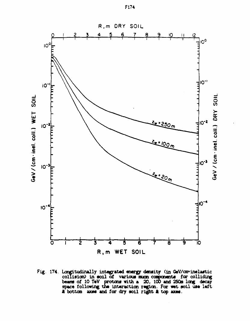
..J -0 (/)
I-w 3: ---0 u
Qi c: ·-. E u -...... > C>
(.!)
F174
R,m ORY SOIL
0 2 3 4 5 6 7 8 9 10 11 12
10·1
10·2
10"3
0
Fig. 174.
2 3 4 s R, m WET
6
SOIL
7 a
10· 1
10·2
10"3
9 10
Lcqitudinal.ly integrated energy derlsit.y (in GeV/cm-inela.stic: collision) in soil of varicq lllJCll c~ ... ta far colli~ beams of 10 TeV protal8 wi.Ui a 20. 1 and 2SQa l~ decay space foll~ the int.enct.icz regicz. Far wet. eoil uae left. I: bottan axes and far dry soil right. .t tcip axes.
...i
0 en >-a: c --Q u -QI c
e u -....... > QI
(.!)

10·1
..J 0 (/)
I-U.I ~
10·2 ---0 u
II> c ·-. e u
10"3 -..... > II>
<.::>
0
Fig. 175.
F175
R,m DRY SOIL
2 3 4 5 6 7 8 9 IQ 11 12
2 3 4 5
R, m WET
6
SOIL
7 8 9
10·1
10·2
10"3
10
l..a!gitu.:iin&l.ly integrated cm17 density <in GeV/cm•inelastic collisiai.> in 90il of vartous lllXl1 crn411ets far -colliding beams of 20 TeV protcN with a 20. 100 and 25Qn l~ decay space foll~ the interact.ia1 regiCll. Far wet eoil un left t bottc:m axes and far dry 90il right t top axes.
...J -0 (/)
>-a:: 0
--c; u
-II> c . e u -..... > II>
<.::>

7
6
_J
0 V> 5 I-w 3:
E 4
--0 JI 3 a::
I
a::
2
1
20
100 I -...
200
r--_
z ,ft WET
300 I
SOIL
400
-..............
~ "-~
10-•
-15 IO
500 I
10·•7
""
600
"'--
-........
t'--.:: -
- 20 --
" -
"""-. -
' - 15 ~
-- IO -- r---. -
r---. -
- ----
- 5 -
--
40 fiO 00 IQ() 120 140 160 180 13 200 BACK WALL
z ,m WET SOIL
_J
0 V>
I-w 3
-~ --
0 ~
a:: I
a::
fig. 176. Cant.ours or erpal <11:.e "'fllvalent. <in rfml'inel....t.ic collisioo> in soil side wall of colhsaun hall due lo - roe colli~ beam of 5 TeV each. A i.. tJuck be;aoipipe is p.-esait. s.c<SJt.aurs -1 be aait.ted foe cl...-it.y o.- due lo irt.at.ist.ic'"1 uncertauat.y
..., .... .._., 11\

7
6
....J
0 (/) 5 t--w 3:
E 4
. 0 ~ 3 fl::
I
a::
2
Fig 171
100 -- ·-
I
20 40
z ,fl WET SOIL
200 -- - - 300 400 - - - 500 - 600 - - -- r-._ I l I '"" --- f'.... -~ -
'-... 1017 -r--;..: - 20 .....
0--.
.
~ .
~ 15 -Hi
IO .
- r--r--. .
~ .
- 10 ..... !'.: .
-
1615 .
- 5 -
---
60 80 100 120 140 160 180 I 200 BACK WALL
z,m WET SOIL
_J
0 (/)
1--w ~
-.... --0 ~
a:: • a::
Catt.ours of "'fal - «fUvalait. <m r-'inelast.ic rolhsiaa> m sen I side ...i I of col11s1m hio.ll - I.a .... f..- colliding a- of al TeV each. A t.. Uuck 1Jeamp1pe 1s present. S.cmtours _, be outt.ed f..- clanLJ or - t.o at.at.urticill uncerta.111ty
....., .... :j

"
SID£ WALL
_J
g ..... ~ E
4J c c :::> -0::
I
0::
10
J ~
8
7 I-
6
5 ~
4
3 L-
2
I -.......
5 10 ---.. I I II I t
r
- t--- "-
t--_ 1013
I 2 3
z ,ft WET SOIL
15 20 25 30
30 I I I I I I 11 I I I I I I -.
I \n!.i5' ---. .
- 25 . --
_j . 20 0
(/)
..... w ~
15 -..... -~
-
r--. I0-14 .
r--.
-- -~
---::
4J - c
c . ::I -- 10 0:: . • . 0:: . -
- 5 .
-. -
4 5 6 7 8 9 10 z,m WET SOIL
Fig. 178. Cmttaurs of ...,..i ~ 81fUvalmt. <in .-..IU1elaat.1c rolhs1an> m soil - wall of col11&11I1 hall clJe t.o - flll" rollidilg i- of 20 TeV eadi. A 1- IJuck beaoip1pe is pr-esent. S.:CIIltaura _, be amt.tad fCll" clarit.)' or ... t.o st.at.1st.ical wicert.a.int.y
..,, ...., ...., a: