feeler ft-200-f001 65mm pc-a prog tail stock 0itd min/cont hp rpm 30 min/cont 20 hp /15 – 4,500rpm...
TRANSCRIPT
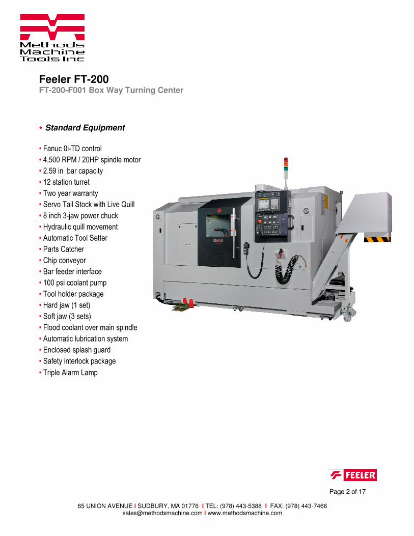
Feeler FT-200 FT-200-F001 Box Way Turning Center
Page 2 of 17
65 UNION AVENUE l SUDBURY, MA 01776 l TEL: (978) 443-5388 l FAX: (978) 443-7466 [email protected] l www.methodsmachine.com
• Standard Equipment
• Fanuc 0i-TD control
• 4,500 RPM / 20HP spindle motor
• 2.59 in bar capacity
• 12 station turret
• Two year warranty
• Servo Tail Stock with Live Quill
• 8 inch 3-jaw power chuck
• Hydraulic quill movement
• Automatic Tool Setter
• Parts Catcher
• Chip conveyor
• Bar feeder interface
• 100 psi coolant pump
• Tool holder package
• Hard jaw (1 set)
• Soft jaw (3 sets)
• Flood coolant over main spindle
• Automatic lubrication system
• Enclosed splash guard
• Safety interlock package
• Triple Alarm Lamp
Feeler FT-200 FT-200-F001 Box Way Turning Center
Page 3 of 17
65 UNION AVENUE l SUDBURY, MA 01776 l TEL: (978) 443-5388 l FAX: (978) 443-7466 [email protected] l www.methodsmachine.com
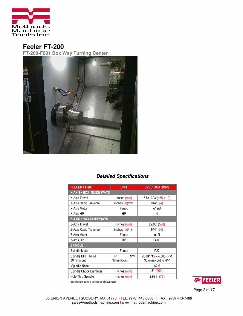
Detailed Specifications
FEELER FT-200 UNIT SPECIFICATIONS
X-AXIS • BOX GUIDE WAYS
X-Axis Travel inches (mm) 6.5+ .393“(165 + 10)
X-Axis Rapid Traverse inches (m)/min 944“ (24)
X-Axis Motor Fanuc α12iB
X-Axis HP HP 4
Z-AXIS • BOX GUIDEWAYS
Z-Axis Travel inches (mm) 22.83” (580)
Z-Axis Rapid Traverse inches (m)/min 944” (24)
Z-Axis Motor Fanuc α12i
Z-Axis HP HP 4.0
SPINDLE
Spindle Motor Fanuc P22
Spindle HP/ RPM 30 min/cont
HP RPM 30 min/cont
20 HP /15 – 4,500RPM 30 mins/cont to H/P
Spindle Nose - A2-6
Spindle Chuck Diameter Inches (mm) 8“ (200) Hole Thru Spindle Inches (mm) 2.99 in (76)
Specifiations subject to change without notice
Feeler FT-200 FT-200-F001 Box Way Turning Center
Page 4 of 17
65 UNION AVENUE l SUDBURY, MA 01776 l TEL: (978) 443-5388 l FAX: (978) 443-7466 [email protected] l www.methodsmachine.com
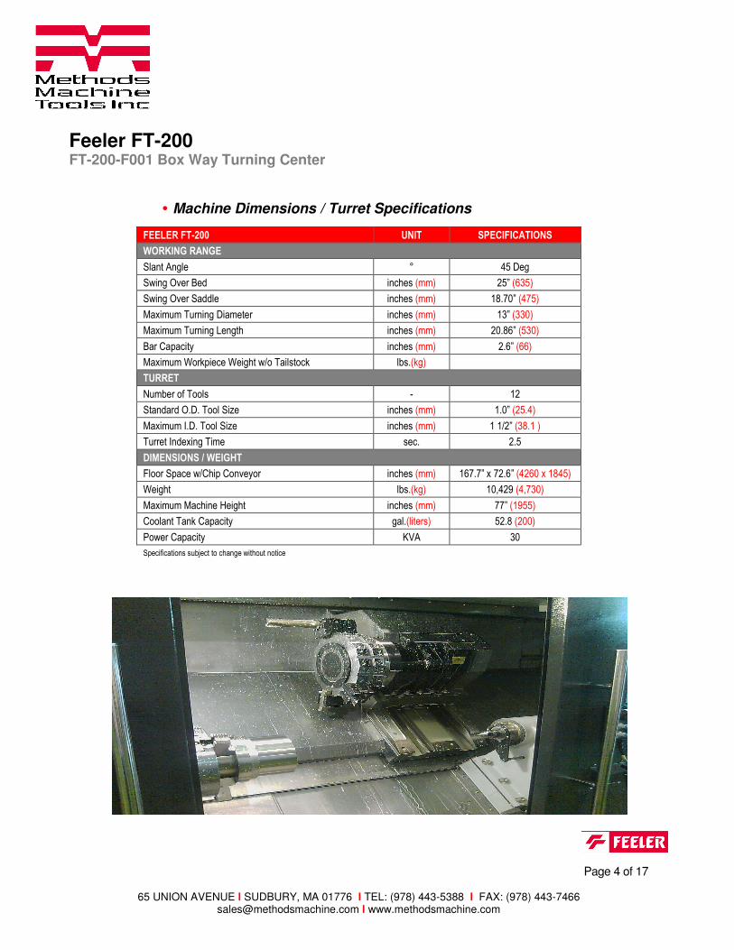
FEELER FT-200 UNIT SPECIFICATIONS
WORKING RANGE
Slant Angle ° 45 Deg
Swing Over Bed inches (mm) 25” (635)
Swing Over Saddle inches (mm) 18.70” (475)
Maximum Turning Diameter inches (mm) 13” (330)
Maximum Turning Length inches (mm) 20.86” (530)
Bar Capacity inches (mm) 2.6” (66)
Maximum Workpiece Weight w/o Tailstock lbs.(kg)
TURRET
Number of Tools - 12
Standard O.D. Tool Size inches (mm) 1.0” (25.4)
Maximum I.D. Tool Size inches (mm) 1 1/2” (38.1 )
Turret Indexing Time sec. 2.5
DIMENSIONS / WEIGHT
Floor Space w/Chip Conveyor inches (mm) 167.7” x 72.6” (4260 x 1845)
Weight lbs.(kg) 10,429 (4,730)
Maximum Machine Height inches (mm) 77” (1955)
Coolant Tank Capacity gal.(liters) 52.8 (200)
Power Capacity KVA 30
Specifications subject to change without notice
• Machine Dimensions / Turret Specifications
Feeler FT-200 FT-200-F001 Box Way Turning Center
Page 5 of 17
65 UNION AVENUE l SUDBURY, MA 01776 l TEL: (978) 443-5388 l FAX: (978) 443-7466 [email protected] l www.methodsmachine.com
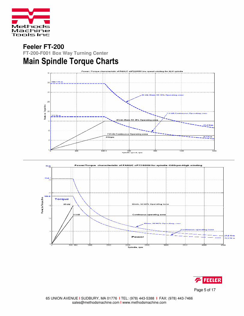
Main Spindle Torque Charts
Feeler FT-200 FT-200-F001 Box Way Turning Center
Page 6 of 17
65 UNION AVENUE l SUDBURY, MA 01776 l TEL: (978) 443-5388 l FAX: (978) 443-7466 [email protected] l www.methodsmachine.com
CONSTRUCTION
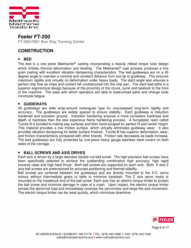
• BED
The bed is a one piece Meehanite casting incorporating a heavily ribbed torque tube design
which inhibits thermal deformation and twisting. The Meehanite cast process produces a fine grain casting with excellent vibration dampening characteristics. The bed guideways are on a 45 degree angle to maintain a minimal and constant distance from tool tip to guideway. This ensures maximum rigidity and virtually no deformation under heavy loads. The slant angle also ensures a perfect chip flow as chips and coolant fall unobstructed into the chip pan. The slant bed lathe is a superior ergonomical design because of the proximity of the chuck, turret and tailstock to the front of the machine. The ease with which operators are able to load/unload parts and change tools minimizes fatigue.
• GUIDEWAYS All guideways are wide wrap-around rectangular type for unsurpassed long-term rigidity and accuracy. The guideways are widely spaced to ensure stability. Each guideway is induction hardened and precision ground. Induction hardening ensures a more consistent hardness and depth of hardness than the less expensive flame hardening process. A fluroplastic resin called Turcite B is bonded to mating way surfaces and then hand scraped for perfect fit and center height. This material provides a low friction surface, which virtually eliminates guideway wear. It also provides vibration dampening for better surface finishes. Turcite B has superior deformation, wear, and friction characteristics compared with other brands. Friction rate decreases as loads increase. The bed guideways are fully protected by one-piece heavy gauge stainless steel covers on both sides of the carriage.
• BALL SCREWS AND AXIS DRIVES Each axis is driven by a large diameter double-nut ball screw. The high precision ball screws have been specifically selected to achieve the outstanding combination high accuracy, high rapid traverse rates and high feed thrust. Both ball screws are supported on each end. Both X and Z axis ball screws are pretensioned for accurate positioning and thermal stability. Ball screws are centered between the guideways and are directly mounted to the A.C. servo motors without intermediate gears or belts to minimize backlash. The Z axis servo motor is mounted on the headstock end of the ball screw. Each axis has an electric torque limiter to protect the ball screw and minimize damage in case of a crash. Upon impact, the electric torque limiter senses the abnormal load and immediately reverses the servomotor and stops the axis movement. The electric torque limiter can be reset quickly, which minimizes downtime.
Feeler FT-200 FT-200-F001 Box Way Turning Center
Page 7 of 17
65 UNION AVENUE l SUDBURY, MA 01776 l TEL: (978) 443-5388 l FAX: (978) 443-7466 [email protected] l www.methodsmachine.com
• SPINDLE AND HEADSTOCK The robust headstock casting is mounted on the same ground surface as the tailstock to maintain perfect alignment and center height regardless of the bed temperature. The headstock has ribs on the outside of the casting to increase the surface area for heat dissipation. The heavy-duty cartridge type spindle is supported by double row cylindrical roller bearings in the front and rear, and duplex angular thrust bearings in between. Cylindrical roller bearings feature a large contact surface which ensures the highest rigidity for heavy loads and high surface finishes. All spindle bearings are precision class P4 (AFBMA-B7) and are permanently grease lubricated. The precision NTN bearings and perfectly balanced spindle allow up to 4,500 RPM. Front bearing inner diameter is 4.33”.
• SPINDLE DRIVE A high-torque spindle motor provides power for heavy stock removal, reducing the number of roughing passes required. The powerful A.C.Dual Wound motor provides fast spindle acceleration and plenty of low-end torque. Full 20 Hp is available at 400 RPM and 344.1N-m of torgue @ low speed and 254.7N-m torque at 562 RPM @ High Speed . The spindle motor is flange mounted on the side of the bed casting, assuring perfect alignment with the headstock.
• SERVO TURRET --- BMT-65 Bolt On Holders The non-lifting turret design eliminates the possibility of chips reaching the coupling. This heavy-duty turret with 13,668Lb(6,200kgf) of clamping force provides high rigidity for heavy stock removal, fine surface finishes, long boring bar overhang ratios, and extended tool life. Turret clamp is confirmed by a proximity switch. Turret indexing is non-stop, bi-directional with a fast .3 second next station index time. Standard turning tool holders utilize 1" square shank tooling and boring holder capacity is 1 1/2". Holders are interchangeable from station to station.
Feeler FT-200 FT-200-F001 Box Way Turning Center
Page 8 of 17
65 UNION AVENUE l SUDBURY, MA 01776 l TEL: (978) 443-5388 l FAX: (978) 443-7466 [email protected] l www.methodsmachine.com
• SERVO DRIVE PROGRAMMABLE TAILSTOCK Widely spaced guideways and heavy duty design of the tailstock body ensure ample rigidity for both slender and heavy shafts. The quill diameter is 3.93 in. The quill stroke of 3.93 in is activated by foot pedal or program. The tail stock quill has a built in spindle for higher rigidity and load capacity. The tailstock body is positioned by a ball screw ,servo driven E Axis for fast positioning and is hydraulically clamped in position with 900 mm travel.
• AUTOMATIC TOOL SETTER ( Standard ) Tool offsets can be quickly and conveniently set with the automatic tool setter. The tool setting arm is mounted next to the chuck and swings down for setting tool offsets. The arm moves up and down manually or by program. The arm is made of tubular steel to minimize thermal expansion. A four position touch sensor mounted on the end of the arm allows tool setting in any direction. As tools are touched-off on the sensor, tool offset values are automatically calculated and entered.
• PART CATCHER The part catcher permits unattended operation with a barfeeder. The part catcher design allows the basket to remain vertical until just before part is discharged through an opening in the machine door. Parts accumulate in a box mounted in the door. The part catcher can handle parts 7.87” long, up to the diameter of the machine bar capacity. Maximum part weight is 4.4 lbs.
• COOLANT SYSTEM A 1.2 Hp high capacity multistage centrifugal pump delivers a high volume coolant through the turret to ball nozzles at each turret station. The pump delivers 100 PSI of pressure, High coolant pressure also significantly increases tool life. The FT-200 has a 53 gallon coolant tank The large coolant tanks and chip pans are separate from the machine bed, preventing heat transfer from the coolant to the machine casting. The coolant pan is mounted on rollers to facilitate removal for cleaning. Screen filters prevent small chips from reaching the coolant pump.
Feeler FT-200 FT-200-F001 Box Way Turning Center
Page 9 of 17
65 UNION AVENUE l SUDBURY, MA 01776 l TEL: (978) 443-5388 l FAX: (978) 443-7466 [email protected] l www.methodsmachine.com
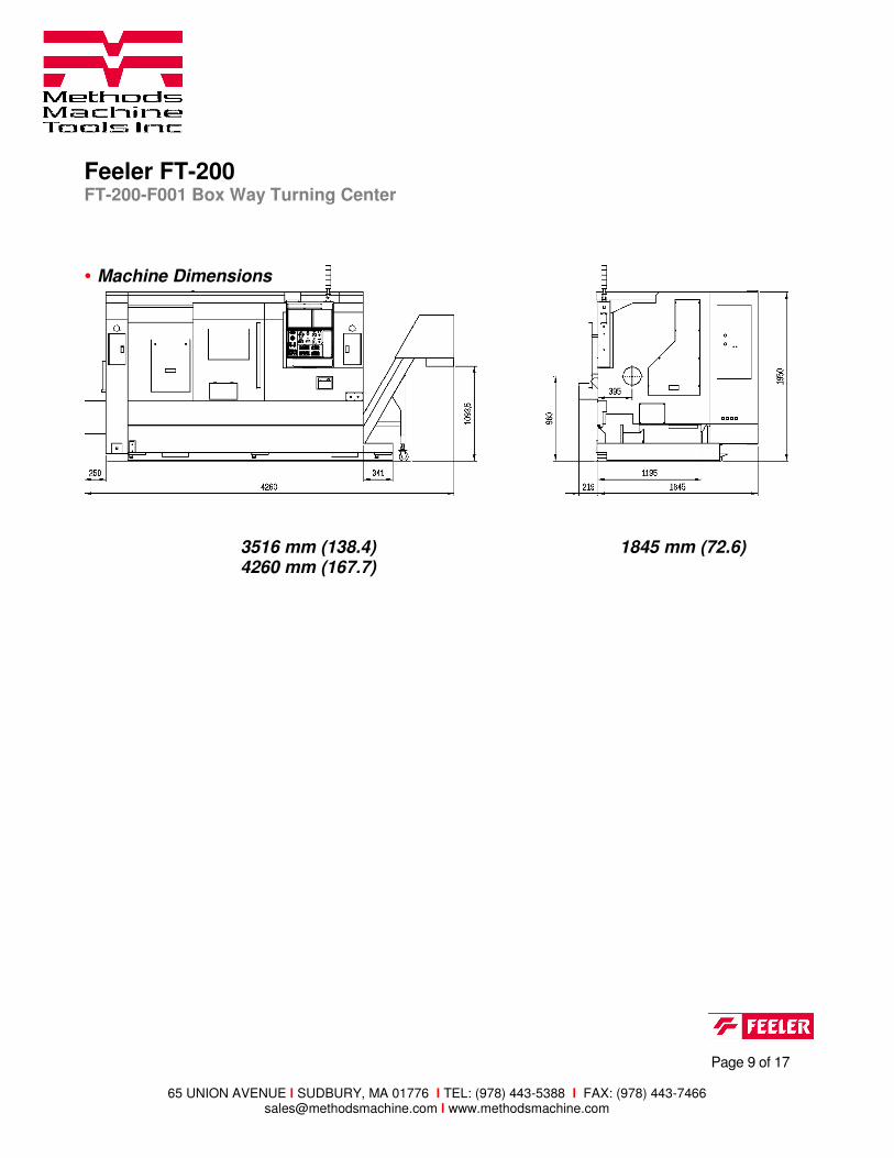
3516 mm (138.4) 1845 mm (72.6) 4260 mm (167.7)
• Machine Dimensions

Feeler FT-200 FT-200-F001 Box Way Turning Center
Page 10 of 17
65 UNION AVENUE l SUDBURY, MA 01776 l TEL: (978) 443-5388 l FAX: (978) 443-7466 [email protected] l www.methodsmachine.com
Standard Tooling Package
FT-200 tooling system (inch)
QTY P/N DESCRIPTION QTY P/N DESCRIPTION
1 MF05000342 BORING BAR SLEEVE, 0.5" 4 MF05000277 O.D. + FACE HOLDER
1 MF05000341 BORING BAR SLEEVE, 0.625" 2 MF05000255 I.D. + FACE HOLDER
1 MF05000340 BORING BAR SLEEVE, 0.75" 5 MF05000337 U DRILL HOLDER, 1.25"
1 MF05000339 BORING BAR SLEEVE, 1.00" 1 MF05000279 U DRILL HOLDER, 1.50"