feasibility study and experimental verification of
TRANSCRIPT

Feasibility Study and Experimental Verificationof Simplified Fiber-Supported 60-GHz PicocellMobile Backhaul LinksVolume 5, Number 4, August 2013
Alexander LebedevXiaodan PangJ. J. Vegas OlmosMarta BeltranRoberto LlorenteSøren ForchhammerIdelfonso Tafur Monroy
DOI: 10.1109/JPHOT.2013.22770111943-0655 � 2013 IEEE

Feasibility Study and ExperimentalVerification of Simplified Fiber-Supported60-GHz Picocell Mobile Backhaul Links
Alexander Lebedev,1 Xiaodan Pang,1 J. J. Vegas Olmos,1 Marta Beltran,2Roberto Llorente,2 Søren Forchhammer,1 and Idelfonso Tafur Monroy1
1DTU Fotonik, Department of Photonics Engineering, Technical University of Denmark,2800 Kongens Lyngby, Denmark
2Valencia Nanophotonics Technology Center, Universidad Politecnica de Valencia,46022 Valencia, Spain
DOI: 10.1109/JPHOT.2013.22770111943-0655 � 2013 IEEE
Manuscript received July 5, 2013; revised July 29, 2013; accepted July 30, 2013. Date of currentversion August 20, 2013. The work of J. J. Vegas Olmos was supported in part by the Marie CurieProgram through the WISCON project. M. Beltran and R. Llorente were supported by the SpainNational Plan TEC2012-38558-C02-01 MODAL project. Corresponding author: A. Lebedev (e-mail:[email protected]).
Abstract: We propose and experimentally demonstrate a fiber-wireless transmissionsystem for optimized delivery of 60-GHz radio frequency (RF) signals through picocellmobile backhaul connections. We identify advantages of 60-GHz links for utilization inshort-range mobile backhaul through feasibility analysis and comparison with an alternativeE-band (60–90 GHz) technology. The 60-GHz fiber-wireless-fiber setup is then introduced:two spans of up to 20 km of optical fiber are deployed and bridged by up to 4 m of wirelessdistance. The 60-GHz radio-over-fiber technology is utilized in the first span of fibertransmission. The system is simplified and tailored for delivery of on-off keying data signalsby employing a single module for lightwave generation and modulation combined with asimplified RF downconversion technique by envelope detection. Data signals of 1.25 Gb/sare transmitted, and a bit-error-rate performance below the 7% overhead forward-error-correction limit is achieved for a range of potential fiber deployment scenarios. A spuriousfree dynamic range of 73 dB-Hz2=3 is attained for a frequency-doubling photonic RF upcon-version technique. The power budget margin that is required to extend the wirelesstransmission distance from 4 m to a few hundred meters has been taken into account in thesetup design, and the techniques to extend the wireless distance are analyzed.
Index Terms: Microwave photonics, radio over fiber, optical communications.
1. IntroductionMobile traffic is predicted to grow at a fast pace with video and data communication playing a largerrole than voice communication and boosting the capacity requirements [1], [2]. There is a strongdemand for larger capacity short range backhaul links supporting picocell connections in dense urbanareas [3]. In metropolitan small cell wireless backhaul for picocell wireless networks, the maximumcapacity provision is essential, and the cell site spacing is limited to less than 1 km distance [3].
The 60 GHz wireless technology has been already widely adopted by industry for applicationssuch as wireless Gigabit Ethernet bridges reaching distances up to 1 km [4]–[6] and high-definitionmultimedia interface (HDMI) cable replacement [7]. There is an ongoing research and industrialdevelopment in application of the 60 GHz technology for the wireless personal area networking(WPAN) [8], data center interconnects [9]–[11] and mobile backhaul links [12], [13].
Vol. 5, No. 4, August 2013 7200913
IEEE Photonics Journal 60-GHz Picocell Mobile Backhaul Links

Telecommunication services such as broadband compressed and uncompressed high-definition(HD) video transmission in the 60 GHz electrical only [14]–[16] and combined 60 GHz fiber-wirelesssetups [17]–[22] have been recently reported. Advantages of the 60 GHz links for bandwidth-demanding applications include unlicensed operation in up to 9 GHz of spectrum depending on thenational wireless spectrum regulations, availability of narrow-beam compact antennas, and a highlevel of frequency reuse [23].
Recent industrial reports indicate the rapid progress in the 60 GHz electrical signal generation andcomponent miniaturization [7], [8], [24]. As a result of these developments, there appears also agrowing need to transport the RF signals across the optical fiber infrastructure. Photonic RFgeneration techniques are complementary to electronic techniques and are deployed for low-loss,low electromagnetic interference interconnection of wireless base stations (BS) to the central office(CO) over preexisting fiber infrastructure [25]. The recent development of highly linear high powerphotoreceivers [26] combining advancements in optoelectronics and mm-wave electronics furtherstrengthens the potential for commercial deployment of 60 GHz fiber-wireless links.
For mm-wave radio transmission, the simplicity and low cost of BS is advantageous as utilizationof the mm-wave bands would require a large number of BSs within a small geographical area. Inorder to simplify the BSs in a network with a fiber connection between the CO and the BS, a radioover fiber (RoF) technology was proposed. In RoF, the BSs are simplified to perform the functions ofoptical-to-electrical (O/E) conversion, RF amplification and filtering, while expensive mm-wave radiofrequency (RF) generation and mixing are avoided at the BSs [27]–[32]. Generation of RoF signalscan be performed with diverse optical components [33]–[36] and can be designed transparent toadvanced modulation formats [37].
In this paper, we study the application of the 60 GHz wireless technology for providing Gigabitpicocell wireless backhaul links fully integrated in a metro/access fiber network. State-of-the-artresearch on the fiber-wireless mobile backhaul links includes studies on microwave and E-band(60–90 GHz) technologies [38], [39]. In this work, we argue that the deployment of the 60 GHz linksfor fiber-supported picocell wireless backhaul is beneficial in terms of the link budget, the installationtime and the capacity availability for the unlicensed use.
We propose a simplified system in which integrated distributed feedback laser and electro-absorption modulator (DFB-EAM) modules are used for the lightwave generation and data modu-lation in both RoF and baseband fiber links. It is important to consider the low-cost broad linewidthoptical signal generation with a DFB laser in order to tailor the system for simplified on-off keying(OOK) modulation/envelope detection systems suitable for wireless Gigabit backhaul transmission.A broader linewidth of the laser is also reported to increase the threshold for the stimulated Brillouinscattering (SBS) effect [40].
Bit error rate (BER) performance below the 7% overhead forward error correction (FEC) limit for1.25 Gbps data signal is reported for transmission through a standard single mode fiber (SSMF) linkof 20 km, 4 m of wireless distance, and a second span of 20 km SSMF. Given that the wirelessdistance performance is only tested for up to 4 m because of laboratory space limitations, wepropose and analyze methods for further wireless distance extension. In this paper, we significantlyextend our work presented in [41] through the report on spurious free dynamic range (SFDR), thefeasibility study, updated and extended state-of-the-art in the field and the revised conclusions.
This paper is organized as follows: In Section 2, network architecture of the proposed 60 GHzmobile backhaul system is presented. In Section 3, the feasibility of deployment of 60 GHz links forpicocell mobile backhaul connections is analyzed in comparison to the E-band technology. InSection 4, the experimental setup for validation of the proposed architecture is presented. Mea-surements of the dynamic range of the RoF system in terms of nonlinearities are presented inSection 5. The experimental data are analyzed and the results are discussed in Section 6. Finally,we conclude the paper in Section 7.
2. Network Architecture and Potential Application ScenariosIn densely populated metropolitan areas, deployment of new mobile backhaul connections on awire becomes prohibitive due to increased installation time and decreased economical feasibility
IEEE Photonics Journal 60-GHz Picocell Mobile Backhaul Links
Vol. 5, No. 4, August 2013 7200913

[42]. Contrary to wired solutions, point-to-point mm-wave links can be installed quickly with wirelessaccess points mounted on roofs, walls, or telecommunication poles. As shown in Fig. 1, BS1�BS2
link represents the urban mobile backhaul connection. Fiber interface to the BS1 and the BS2
provides connection to the CO and the suburban BS3, respectively. BS1, BS2, and BS4 are sup-porting multiple urban picocells, and BS3 is supporting the suburban picocells. By adding a fiberconnection from BS2 to BS3, a hybrid solution for metropolitan/suburban backhaul of picocell net-works is provided.
We employ optical fiber for the RF signal delivery from the CO to the BS1. The data are thentransmitted wirelessly to the BS2 on the 60 GHz RF carrier. Outside of the central urban area,backhauling is then performed using preexisting optical fiber infrastructure (BS2�BS3 connection).The signal arrives to the BS3 in a baseband format where it can be subsequently upconverted forBS-access point communication.
It is also important to point out that the fiber infrastructure is expected to be shared betweenbaseband digital systems providing broadband fiber-to-the-home (FTTH) services simultaneouslywith backhaul traffic delivery. This architecture can also be extended to fit the RF generation anddelivery in wavelength division multiplexing (WDM) systems [43], [44], enabling simultaneousdelivery of the 60 GHz RF carrier in CO-BS1�BS2 and CO-BS1�BS4 directions.
3. Feasibility Modeling of Wireless Mobile Backhaul Links Transmissionin the 60 GHz BandIn this section, we perform a large-scale mm-wave channel modeling in which V (50–75 GHz) andE (60–90 GHz) band line-of-sight (LOS) outdoors RF transmission systems are compared. Weargue that the use of the 60 GHz technology is advantageous for the point-to-point picocell mobilebackhaul deployment on distances up to a few hundred meters.
Attenuation of the RF signals during air transmission for the LOS outdoors case consists of twomajor components: the free space path loss and the loss due to atmospheric absorption onmoleculesof oxygen and water vapor. We place the center frequencies in V- and E-band at the centers of
Fig. 1. Network scenario for the 60 GHz urban picocell mobile backhaul link fully supported with adiverse fiber infrastructure. CO: central office, BS: base station, FTTH: fiber to the home. BS1 and BS2operate on the 60 GHz frequency, BS3 is suggested to operate in the lower frequency licensedbandwidth.
IEEE Photonics Journal 60-GHz Picocell Mobile Backhaul Links
Vol. 5, No. 4, August 2013 7200913

spectrum windows available for unlicensed and Flight licensing_ deployment (60 GHz, 73.5 GHz, and83.5 GHz).
The free space path loss is calculated using the Friis transmission equation. By including theattenuation of the signal related to atmospheric absorption, we arrive to the Eq. (1) for calculation ofthe path loss for air transmission:
� ¼ 20 log104�R�
� �þ Lgas �Gtx �Grx ; (1)
where R (m) is a transmission distance, � (m) is a wavelength of the signal, Lgas (dB) is theatmospheric absorption related attenuation, Gtx and Grx are gain of transmitting and receivingantennas respectively (we set these to 25 dBi each). Gaseous attenuation including both watervapor and oxygen-related absorption peaks at the 60 GHz frequency reaching the value ofapproximately 15 dB/km due to the absorption peak on oxygen molecules, however across E-bandcombined attenuation on molecules of oxygen and water vapor is measured to be about 0.4 dB/km[45]. In order to compare the performance of V- and E-band systems for wireless distances suitablefor dense metropolitan backhaul of picocell networks, we plot the results of numerical calculation forthe combined signal attenuation in Fig. 2 (left).
From Fig. 2 (left), it can be seen that the 60 GHz transmission link shows a lower path loss in arange of about 200 m compared to the E-band solution centered at 83.5 GHz and at about130 meters for 73.5 GHz centered E-band link, the attenuation penalty does not exceed 3 dB in thelinks up to 300m. Thus, the 60 GHz links can achieve performance superior/close to the E-band linksin the range up to a few hundred meters in terms of added contributions from the free space path lossand atmospheric absorption on the molecules of oxygen and water vapor.
In Fig. 2 (right) the 60 GHz path loss for indoor wireless distances is presented. We have firstexperimentally measured the RF attenuation in a near-field area where the standard Friistransmission equation does not apply. The Fraunhofer distance defining the border between near-and far-field propagation is calculated according to:
df ¼2D2
�; (2)
where D is the largest dimension of an antenna, in our case it is equal to 0.039 m, and � is awavelength of the radio signal. The results show a close match around the Fraunhofer distancebetween experimentally measured values of attenuation in the near field and values calculatedaccording to Eq. (1) in the far field.
Using the Eq. (1), we obtain that, in order to extend the wireless distance from 4 m to 300 m,42 dB improvement in the electrical link budget is required. It is therefore critical that we designthe laboratory setup capable to accommodate this requirement.
Fig. 2. The combined free space path loss and atmospheric absorption as a function of wirelesstransmission distance for E- and V-band outdoors links (left) and indoor V-band links (right).
IEEE Photonics Journal 60-GHz Picocell Mobile Backhaul Links
Vol. 5, No. 4, August 2013 7200913

Another important performance criterion for wireless communication is stability of the link underthe weather influence. In this paper, we analyze the influence of rain on transmission performance.An estimate of the rain attenuation is given by:
�R ¼ kR�; (3)
where �R (dB/km) is the specific rain-related attenuation, and R (mm/hour) is the rain rate parameterdifferentiating the intensity of a rainfall. The coefficients k and � are frequency dependent and maybe either determined by curve-fitting equations or through a set of specified values given inRecommendation P.838-2 [46]. Rain types are separated as a Fdrizzle: 0.25 mm/hour_, a Flight rain:2.5 mm/hour_, a Fheavy rain: 25 mm/hour_, and a Ftropical rain: 100 mm/hour_ [3]. Fig. 3 (left)presents the simulation results based on the recommendation.
60 GHz links have slightly lower rainfall attenuation values compared to E-band links as depictedin Fig. 3 (left). In Fig. 3 (right) we display the effect that the Fheavy_ and the Ftropical_ rain will have onthe operation of the 60 GHz link in terms of shortening the transmission distance for a given signal-to-noise ratio (SNR) required at the receiver. We define the limit on the path loss by the closeness of the60 GHz RF signal power to the noise floor defined by the Johnson noise. The path loss margin �available for a given requirement on the SNR (we set SNR of 18 dB which for envelope-detectedsignals yields BER less than 10�12), given bandwidth of the signal ðB ¼ 2:5 GHzÞ, given RF powerbefore the antenna ðPtx ¼ 10 dBmÞ is then equal to:
� ¼ Ptx � 10log10ð1000� ktÞ � 10log10ðBÞ � SNR; (4)
where k is a Boltzmann’s constant, and t (K) is a room temperature. We have calculated � to beequal to 72 dB for our bitrate. The values of path loss are then calculated as a sum of (1) and (3) forantenna gain of 25 dBi. As we see in Fig. 3 (right), the influence of weather conditions shortens thereliable wireless link length, however, in order to combat this, FEC techniques are typically used[4], [6]. It is also clear from Fig. 3 (right) that the reliable link length can be extended by increasingthe power at the transmitter or increasing the antenna gain.
Given the modeling results, it is clear that the 60 GHz links are a good solution for the picocellbackhaul transmission systems on a distance up to a few hundred meters in terms of combinedeffects of the free space path loss, the atmospheric absorption and the possible rain attenuation.There are few additional aspects that have to be considered before making a choice between V- orE-band links for deployment in picocell mobile backhaul. First, V-band links provide unlicensedoperation, when E-band transmission requires light licensing which may incur additional delays inthe link installation time. Second, the current market costs of the equipment based on the V-bandtechnology are lower than that of the E-band links [4]. Last, with a quick reduction of power levelwhen the signal is following other than the LOS path, superior multipath interference immunity andhigh frequency reuse are enabled for 60 GHz systems.
Fig. 3. Rainfall attenuation as a function of frequency (left) and combined path loss and rainfallattenuation for 60 GHz RF propagation versus required SNR level (right) as a function of wirelessdistance.
IEEE Photonics Journal 60-GHz Picocell Mobile Backhaul Links
Vol. 5, No. 4, August 2013 7200913

We believe that the feasibility study presented in this section supports the relevance of studyingthe 60 GHz links for picocell mobile backhaul. In the next sections, a simplified 60 GHz fiber-wireless-fiber setup is built, and its performance is characterized experimentally.
4. Experimental Setup DescriptionThe schematics of the experimental setup of the 60 GHz fiber-wireless picocell mobile backhaul linkincluding two spans of fiber and a single 60 GHz wireless link in between is presented in Fig. 4. Foursubsystems are emulated: a CO transmitter and three BSs ðBS1�BS3Þ. RoF generation and datamodulation are located at the CO; BS1 performs the O/E conversion and amplifies the 60 GHz RFsignal before the radiation, BS2 performs the RF downconversion and remodulation onto thelightwave. BS3 recovers the original baseband data by O/E conversion.
A DFB-EAM module was used to produce a lightwave at a wavelength � ¼ 1550 nm with 4 dBmof optical power. A 1.25 Gbps nonreturn to zero (NRZ) pseudorandom binary sequence (PRBS)with a word length of 215 � 1 generated by a pulse pattern generator (PPG) was directly modulatedonto the lightwave at the DFB-EAM1. The use of the DFB-EAM for lightwave generation and datamodulation relaxes requirements for a peak-to-peak voltage of the electrical signal driving themodulator and simplifies the overall system installation. Chirp effects common to EAM technologywere controlled through application of an optimal voltage.
RF modulation of the lightwave was performed using a single-drive Mach-Zehnder modulator(MZM). A polarization controller (PC) was placed before the MZM in order to minimize thepolarization-dependent loss. The MZM was biased at a minimum transmission point and driven by ahigh-power sinusoidal local oscillator (LO) RF ðþ18 dBm; fLO ¼ 29:5 GHzÞ, resulting in asuppression of the original optical carrier and increase of optical power in upper and lowersidebands separated by twice the original RF frequency 2fLO . This technique for generation of RoFsignals is known as an optical carrier suppression (OCS) technique [47]. By using the OCS method,the requirements for high frequency RF components at the CO are alleviated, and high quality phasenoise performance is obtained due to the fact that upper and lower sidebands are produced by thesame laser. The optical spectrum of the generated double-sideband with a suppressed carrier(DSB-SC) signal is presented in Fig. 5 (left). A suppression of the optical carrier relative to the RF-produced sidebands of approximately 20 dB was achieved constrained by both the polarizationalignment and the extinction ratio of the modulator.
The signal was subsequently coupled into an Erbium doped fiber amplifier (EDFA) in order toimprove the power budget before the launch into the fiber. Subsequently, fiber transmission wasperformed through SSMF and non-zero dispersion shifted fiber (NZDSF). We detected the electricalRF signal through photomixing at a 75 GHz bandwidth p-i-n photodiode ðPD1Þ. The variable opticalattenuator ðVOA1Þ was placed before the PD1 in order to control the power entering the PD1. After
Fig. 4. Laboratory setup for a fiber-wireless-fiber 60 GHz link. DFB-EAM: distributed feedback laserintegrated with an electro-absorption modulator, PPG: pulse pattern generator, MZM: Mach-Zehndermodulator, LO: local oscillator, EDFA: Erbium doped fiber amplifier, HF PD: high frequency photodiode,LNA: low noise amplifier, BPF: bandpass filter, VOA: variable optical attenuator, VEA: variable electricalattenuator, PA: power amplifier, ED: envelope detector, BERT: bit error rate tester, CO: central office,BS: base station, SSMF: standard single mode fiber, NZDSF: non-zero dispersion shifted fiber, MMF:multimode fiber.
IEEE Photonics Journal 60-GHz Picocell Mobile Backhaul Links
Vol. 5, No. 4, August 2013 7200913

photomixing, the 60 GHz RF signal was amplified with a 40 dB gain double-stage low noiseamplifier (LNA), passed through a bandpass filter and radiated with a horn antenna (þ25 dBi gain).The spectrum of the modulated RF signal is depicted in Fig. 5 (right). The path loss for 4 m wirelessdistance including the combined gain of antennas (50 dBi) is equal to approximately 31 dB whichwas calculated using the Eq. (1) presented in Section 3. The equivalent omnidirectional path loss(antenna gain is excluded) is equal to 81 dB.
After reception with an equivalent antenna, the signal was amplified with a 40 dB gain LNA. Wehave then employed a variable electrical attenuator (VEA) and a power amplifier (PA) in order toemulate the effect of the possible wireless distance extension on the system performance. The VEAhas been set to attenuate the signal by 18 dB throughout the measurements. The signal was thenfiltered and the data signal were downconverted from RF into baseband at a zero-biased Schottkydiode serving as an envelope detector (ED). We refer the readers to [48] for a thorough study onbasic principles of Schottky diodes’ operation. Main advantage of the envelope detection techniqueis that it allows performing the RF signal downconversion without using an RF LO and a phaselocked loop circuitry required for the synchronous mixing detection technique. Following the ED, thesignal was amplified to bring the peak-to-peak voltage level of the signal to a value required foreffective driving of the DFB-EAM2.
After the subsequent remodulation on the lightwave, the signal was passed through diverse typesof optical fiber. We have included multimode fiber (MMF) in a second span of fiber transmission inorder to address the fiber distribution in network connections where the metro/access delivery isintegrated with MMF-wired local area network (LAN) distribution. The baseband electrical data werefinally recovered with a 10 GHz bandwidth p-i-n PD. After amplification, it was fed to a BER tester(BERT) for further signal quality evaluation.
5. Characterization of the SFDRAn SFDR measurement is needed in order to quantify performance of the RoF system in terms ofnonlinearities of link components, i.e. appearance of spurious harmonics of the RF signal that arelocated in the bandwidth of data modulation and contribute to BER deterioration. The SFDR of thesystem is the range between the smallest signal that can be transmitted and received by thesystem and the largest signal that can be introduced into the system without creating distortionsabove the noise floor after detection in the bandwidth of interest [49]. SFDR gives better systemperformance estimate than maximum achievable SNR which is constrained by noise floor andsaturation only. Given that in order to extend the wireless link distance for outdoor scenarios weneed to improve the power budget, we have measured the SFDR including EDFA and increasedoptical power into the PD.
In Fig. 6, we present the setup for measuring the SFDR of the modulation and upconversion blockin the system. We built the SFDR setup based on a part of the general setupVa link between theCO and the BS1. The signal is then analyzed directly on the output of the PD.
Fig. 5. Optical spectra of the transmitted signal (left) and RF spectrum of the signal before radiation(right).
IEEE Photonics Journal 60-GHz Picocell Mobile Backhaul Links
Vol. 5, No. 4, August 2013 7200913
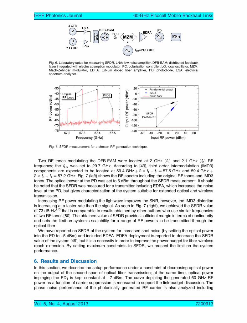
Two RF tones modulating the DFB-EAM were located at 2 GHz ðf1Þ and 2.1 GHz ðf2Þ RFfrequency; the fLO was set to 29.7 GHz. According to [49], third order intermodulation (IMD3)components are expected to be located at 59:4 GHzþ 2� f1 � f2 ¼ 57:5 GHz and 59:4 GHz þ2� f2 � f1 ¼ 57:2 GHz. Fig. 7 (left) shows the RF spectra including the original RF tones and IMD3tones. The optical power at the PD was set to 5 dBm throughout the SFDR measurement. It shouldbe noted that the SFDR was measured for a transmitter including EDFA, which increases the noiselevel at the PD, but gives characterization of the system suitable for extended optical and wirelesstransmission.
Increasing RF power modulating the lightwave improves the SNR, however, the IMD3 distortionis increasing at a faster rate than the signal. As seen in Fig. 7 (right), we achieved the SFDR valueof 73 dB-Hz2=3 that is comparable to results obtained by other authors who use similar frequenciesof two RF tones [50]. The obtained value of SFDR provides sufficient margin in terms of nonlinearityand sets the limit on system’s scalability for a range of RF powers to be transmitted through theoptical fiber.
We have reported on SFDR of the system for increased shot noise (by setting the optical powerinto the PD to +5 dBm) and included EDFA. EDFA deployment is reported to decrease the SFDRvalue of the system [49], but it is a necessity in order to improve the power budget for fiber-wirelessreach extension. By setting maximum constraints to SFDR, we present the limit on the systemperformance.
6. Results and DiscussionIn this section, we describe the setup performance under a constraint of decreasing optical poweron the output of the second span of optical fiber transmission; at the same time, optical powerimpinging the PD1 is kept constant at �7 dBm. The curve depicting the generated 60 GHz RFpower as a function of carrier suppression is measured to support the link budget discussion. Thephase noise performance of the photonically generated RF carrier is also analyzed including
Fig. 6. Laboratory setup for measuring SFDR. LNA: low noise amplifier, DFB-EAM: distributed feedbacklaser integrated with electro absorption modulator, PC: polarization controller, LO: local oscillator, MZM:Mach-Zehnder modulator, EDFA: Erbium doped fiber amplifier, PD: photodiode, ESA: electricalspectrum analyzer.
Fig. 7. SFDR measurement for a chosen RF generation technique.
IEEE Photonics Journal 60-GHz Picocell Mobile Backhaul Links
Vol. 5, No. 4, August 2013 7200913

measurements for different types of optical fiber in the first fiber transmission span. BER has beenused as a main criterion of system performance constrained by the values of optical powerimpinging the PD2, the length of fiber and the wireless transmission distance.
First, we present the results with relaxed requirements for the first span of fiber transmission interms of dispersion in Fig. 8 (left). We transmit the signal back-to-back (B2B) or employ 5.5 kmNZDSF in the first fiber span of the setup and fiber of different lengths and types in the second span.Fig. 8 (left) shows that deployment of SSMF and NZDSF in the second span of transmissionintroduces no penalty compared to B2B case; however, in all three cases of fiber deployment (B2B,SSMF, NZDSF) in the second span, we observed an error floor on BER performance atapproximately 10�8 level for 1 m of wireless distance. We suggest that the error floor is not relatedto chromatic dispersion (CD) given that the distortion of 60 GHz RoF 1.25 Gbps data signal due toCD can be considered negligible in 5.5 km NZDSF and absent in B2B transmission case. Wesuggest that the error floor is therefore related to degradation of the SNR in the system and to themodulation efficiency of the DFB-EAM2 which depends on the peak-to-peak voltage level of thebaseband electrical signal recovered with ED. Optical B2B curve for 4 m wireless distance in Fig. 8(left) indicates that, by extending the wireless distance, we are improving the DFB-EAM2
modulation performance, and the error floor is avoided for extended wireless distances for the sameSNR before remodulation on the lightwave. We therefore conclude that presence of the error floor isnot related to performance of the wireless channel, i.e. only extension of the wireless distance, andcan be mitigated by installing an automatic level control circuit before remodulation on theDFB-EAM2 to preserve high modulation efficiency and avoid overmodulation.
We then proceeded to emulate deployment of larger distances of fiber in the first span oftransmission. Fig. 8 (right) indicates that, when we deploy about 20 km of fiber in both spans, anerror floor is present at about a 10�6 level. Presence of an error floor is now related to CD impairingthe signal in the first span of transmission. When two sidebands are photomixed at the PD, thesignal suffers from intersymbol interference caused by a delay between the pulses transmitted onupper and lower sidebands which is reported as a Fbit walk-off_ in [51]. However, the periodicdispersion-induced RF power fading is eliminated when the optical carrier is suppressed [51]. Forboth 1 m and 4 m wireless transmission cases employing fibers with different values of dispersion(NZDSF, SSMF), we demonstrate BER performance well below the 2� 10�3 limit corresponding toa 7% FEC overhead. BER degradation due to the time shifting of the pulses in the upper and lowersidebands in the first fiber span can be overcome by using a single sideband modulation or diverseCD compensation techniques, however this would increase the setup complexity. Overall,considering the original goal of building a simplified setup, the fact that the penalty is also relatedto multiple noise sources, and the fact that the FEC is typically implemented in the 60 GHz links [4],[6], we believe that our setup will be a suitable solution for simplified fiber-supported 60 GHzpicocell mobile backhaul links.
Fig. 8. BER as a function of optical power measured at the PD2 for B2B/5.5 km NZDSF (left) and22.8 km SSMF (right) of fiber distance in the first span.
IEEE Photonics Journal 60-GHz Picocell Mobile Backhaul Links
Vol. 5, No. 4, August 2013 7200913

We have investigated SSMF deployment interfaced with MMF (Fig. 8, right), an appropriatescenario for this combination will be the interface between the access network deployed usingSSMF and LAN using MMF. Lightwave was centrally launched from SSMF into MMF which enablesmode filtering by exciting only a limited number of lower order modes in the MMF [52]. Intermodaldispersion is thus mitigated because in this case coupling between high and low order modes isreduced significantly. On the receiving side, MMF has been interfaced to the PD by a shortpatchcord of SSMF (used 75 GHz bandwidth PD only had the SSMF interface) by using which werecover the lowest-order mode ðLP01Þ which implies higher power loss on coupling from MMF toSSMF.
RoF systems in general suffer from the high loss on O/E and E/O conversion due to the resistiveimpedance matching being an issue at both the transmitter and the receiver. In Fig. 9, we depictpower of the 60 GHz RF signal as a function of the sideband-to-carrier suppression ratio which wasvaried by applying a changing bias voltage. As depicted in Fig. 9, in our system, high power 30 GHzRF signal (þ18 dBm) applied at the E/O conversion point is subsequently recovered afterphotomixing as a �30 dBm 60 GHz RF signal for optimized value of 20 dB carrier suppression anda fixed PD1 input optical power of 0 dBm. 1 dB reduction in optical power entering the PD will resultin 2 dB reduction in the 60 GHz RF power. Thus, at �7 dBm optical power entering the PD, RF atthe PD output will be equal to �44 dBm.
In order to extend the wireless link length from 4 m to 300 m of wireless distance, we have toaddress the necessary provision of 42 dB power margin compared to the link budget of 4 m wirelessdistance as calculated in Section 3. There are few generally applied techniques to improve theelectrical link budget and increase the wireless transmission distance. First, a common technique isto use antennas of higher gain. For V-band, antennas of 42 dBi gain are commercially availablewhich may simultaneously add 34 dB to a power budget of the link. Second, the link distance can beextended through amplification. VEA-PA combination that we employ at the BS2 may be adjusted tobring the additional 18 dB power without introduction of noise by setting the VEA attenuation to 0.The noise figure of the PA is already a part of the link impairments. Depending on link design, PAmight be also offset to the transmitting side. These two methods combined bring a gain of 52 dB tothe link that surpasses the required margin of 42 dB. However, it must be taken into account for thelink design that, when employing a higher gain antenna, the Fraunhofer distance will increase. For acommercially available lens horn antenna of 42 dBi gain with a diameter of 0.25 m, the Fraunhoferdistance is equal to 25 m.
In this work, we study transmission of the OOK signals. However, transparency for higher ordermodulation formats is an important design criterion for RoF links. High performance of the RFoscillator in terms of phase noise is required to enable such transparency. DSB-SC RoF setups areknown to have an excellent performance in terms of phase noise because the sidebands areproduced by the same laser source and thus are correlated with each other. We depict the phase
Fig. 9. 60 GHz RF power on the PD output as a function of carrier suppression of the DSB-SC signal.
IEEE Photonics Journal 60-GHz Picocell Mobile Backhaul Links
Vol. 5, No. 4, August 2013 7200913
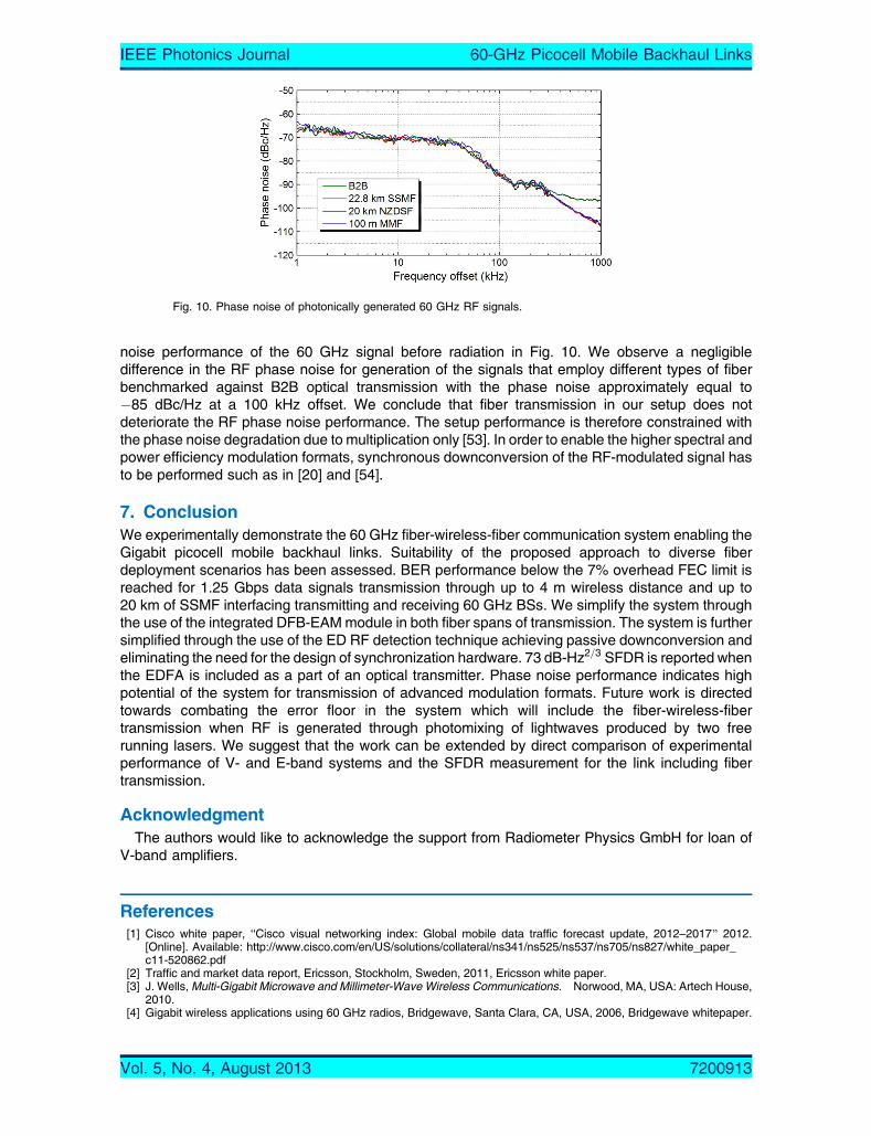
noise performance of the 60 GHz signal before radiation in Fig. 10. We observe a negligibledifference in the RF phase noise for generation of the signals that employ different types of fiberbenchmarked against B2B optical transmission with the phase noise approximately equal to�85 dBc/Hz at a 100 kHz offset. We conclude that fiber transmission in our setup does notdeteriorate the RF phase noise performance. The setup performance is therefore constrained withthe phase noise degradation due to multiplication only [53]. In order to enable the higher spectral andpower efficiency modulation formats, synchronous downconversion of the RF-modulated signal hasto be performed such as in [20] and [54].
7. ConclusionWe experimentally demonstrate the 60 GHz fiber-wireless-fiber communication system enabling theGigabit picocell mobile backhaul links. Suitability of the proposed approach to diverse fiberdeployment scenarios has been assessed. BER performance below the 7% overhead FEC limit isreached for 1.25 Gbps data signals transmission through up to 4 m wireless distance and up to20 km of SSMF interfacing transmitting and receiving 60 GHz BSs. We simplify the system throughthe use of the integrated DFB-EAMmodule in both fiber spans of transmission. The system is furthersimplified through the use of the ED RF detection technique achieving passive downconversion andeliminating the need for the design of synchronization hardware. 73 dB-Hz2=3 SFDR is reported whenthe EDFA is included as a part of an optical transmitter. Phase noise performance indicates highpotential of the system for transmission of advanced modulation formats. Future work is directedtowards combating the error floor in the system which will include the fiber-wireless-fibertransmission when RF is generated through photomixing of lightwaves produced by two freerunning lasers. We suggest that the work can be extended by direct comparison of experimentalperformance of V- and E-band systems and the SFDR measurement for the link including fibertransmission.
AcknowledgmentThe authors would like to acknowledge the support from Radiometer Physics GmbH for loan of
V-band amplifiers.
References[1] Cisco white paper, ‘‘Cisco visual networking index: Global mobile data traffic forecast update, 2012–2017[ 2012.
[Online]. Available: http://www.cisco.com/en/US/solutions/collateral/ns341/ns525/ns537/ns705/ns827/white_paper_c11-520862.pdf
[2] Traffic and market data report, Ericsson, Stockholm, Sweden, 2011, Ericsson white paper.[3] J. Wells,Multi-Gigabit Microwave and Millimeter-Wave Wireless Communications. Norwood, MA, USA: Artech House,
2010.[4] Gigabit wireless applications using 60 GHz radios, Bridgewave, Santa Clara, CA, USA, 2006, Bridgewave whitepaper.
Fig. 10. Phase noise of photonically generated 60 GHz RF signals.
IEEE Photonics Journal 60-GHz Picocell Mobile Backhaul Links
Vol. 5, No. 4, August 2013 7200913

[5] A. Mathew, Local Area Networking Using MillimetreWaves. Acton, MA, USA: NewLANs, Inc., 2005.[6] AIRLINX Communications, Inc. specification datasheet, ‘‘GigaLink 6221/6421/6451[ 2013, (AIRLINX Communications,
Inc.).[7] WirelessHD Specification Version 1.1 Overview, WirelessHD, Morgan Hill, CA, USA, 2010, WirelessHD white paper.[8] WiGig white paper, Defining the future of multi-gigabit wireless communication, Jul. 2010, (WiGig alliance).[9] K. Ramachadran, R. Kokku, R. Mahindra, and S. Rangarajan, B60 GHz data-center networking: Wireless worry less?’’
NEC, Princeton, NJ, USA, Tech. Rep., 2008.[10] S. Kandula, J. Padhye, and P. Bahi, BFlyways to de-congest data center networks,[ in Proc. 8th ACM Workshop Hot
Topics Netw., 2009, pp. 1–6.[11] K. Kawasaki, Y. Akiyama, K. Komori, M. Uno, H. Takeuchi, T. Itagaki, Y. Hino, Y. Kawasaki, K. Ito, and A. Hajimiri,
BA millimeter-wave intra-connect solution,[ in Proc. IEEE Int. Solid-State Circuits Conf., 2010, pp. 414–415.[12] Ceragon application note, Wireless backhaul solutions for small cells, (Ceragon).[13] Sub10 Systems Limited White Paper, ‘‘60GHz metro cell and small cell backhauling for service providers,[ 2011,
(Sub10 Systems Limited).[14] H. Singh, J. Oh, C. Kweon, X. Qin, H. Shao, and C. Ngo, BA 60 GHz wireless network for enabling uncompressed video
communication,[ IEEE Commun. Mag., vol. 46, no. 12, pp. 71–78, Dec. 2008.[15] Z. Lan, J. Wang, C.-S. Sum, T. Baykas, C. Pyo, F. Kojima, H. Harada, and S. Kato, BUnequal error protection for
compressed video streaming on 60 GHz WPAN system,[ in Proc. Int. Wireless Commun. Mobile Comput. Conf., 2008,pp. 689–693.
[16] H. Singh, X. Qin, H. Shao, C. Ngo, C. Kwon, and S. S. Kim, BSupport of uncompressed video streaming over 60 GHzwireless networks,[ in Proc. 5th IEEE Consum. Commun. Netw. Conf., 2008, pp. 243–248.
[17] A. Chowdhury, H.-C. Chien, Y.-T. Hsueh, and G.-K. Chang, BAdvanced system technologies and field demonstrationfor in-building optical-wireless network with integrated broadband services,[ J. Lightw. Technol., vol. 27, no. 12,pp. 1920–1927, Jun. 2009.
[18] A. Lebedev, T. T. Pham, M. Beltran, X. Yu, A. Ukhanova, R. Llorente, and I. Tafur Monroy, BOptimization of high-definition video coding and hybrid fiber-wireless transmission in the 60 GHz band,[ Opt. Exp., vol. 19, no. 26,pp. 895–904, Dec. 2011.
[19] A. Lebedev, J. J. Vegas Olmos, X. Pang, S. Forchhammer, and I. Tafur Monroy, BDemonstration and comparison studyfor V- and W-band real-time high-definition video delivery in diverse fiber-wireless infrastructure,[ Fiber Integr. Opt.,vol. 32, no. 2, pp. 93–104, 2013.
[20] A. Lebedev, J. J. Vegas Olmos, M. Iglesias, S. Forchhammer, and I. T. Monroy, BEnabling uncompressedvideo transmission in double-sideband 60 GHz radio-over-fiber links,[ in Proc. IEEE IPC, 2012, pp. 578–579,Paper WS2.
[21] Z. Tang and S. Pan, BTransmission of 3-Gb/s uncompressed HD video in a optoelectronic-oscillator-based radio overfiber link,[ in Proc. IEEE 13th Topical Meet. SiRF, 2013, pp. 219–221.
[22] J. Guillory, A. Pizzinat, P. Guignard, F. Richard, B. Charbonnier, P. Chanclou, and C. Algani, BSimultaneousimplementation of gigabit Ethernet, RF TV and radio mm-wave in a multiformat home area network,[ presented at the37th Eur. Conf. Exhibition Optical Communication (ECOC), Geneva, Switzerland, 2011, Paper We.7.C.3.
[23] S.-K. Yong, 60 GHz Technology for Gbps WLAN and WPAN: From Theory to Practice. Hoboken, NJ, USA: Wiley,2011.
[24] Siversima application note, ‘‘58–63 GHz V-band converter,[ 2013, (Siversima).[25] C. Lim, A. Nirmalathas, M. Bakaul, P. Gamage, K.-L. Lee, Y. Yang, D. Novak, and R. Waterhouse, BFiber-wireless
networks and subsystem technologies,[ J. Lighwave Technol., vol. 28, no. 4, pp. 390–405, Feb. 2010.[26] S. Fedderwitz, C. Leonhardt, J. Honecker, P. Muller, and A. Steffan, BA high linear and high power photoreceiver
suitable for analog applications,[ in Proc. IEEE IPC, 2012, pp. 308–309, Paper TuL3.[27] K. Xu, X. Sun, J. Yin, H. Huang, J. Wu, X. Hong, and J. Lin, BEnabling ROF technologies and integration architectures
for in-building optical–wireless access networks,[ IEEE Photon. J., vol. 2, no. 2, pp. 102–112, Apr. 2010.[28] A. Kanno, P. T. Dat, T. Kuri, I. Hosako, T. Kawanishi, Y. Yoshida, Y. Yasumura, and K. Kitayama, BCoherent radio-
over-fiber and millimeter-wave radio seamless transmission system for resilient access networks,[ IEEE Photon. J.,vol. 4, no. 6, pp. 2196–2204, Dec. 2012.
[29] X. Zhang, B. Hraimel, and K. Wu, BBreakthroughs in optical wireless broadband access networks,[ IEEE Photon. J.,vol. 3, no. 2, pp. 331–336, Apr. 2011.
[30] X. Li, J. Yu, Z. Dong, and N. Chi, BPhotonics millimeter-wave generation in the E-band and bidirectional transmission,[IEEE Photon. J., vol. 5, no. 1, p. 7 900 107, Feb. 2013.
[31] A. M. Zin, M. S. Bongsu, S. M. Idrus, and N. Zulkifli, BAn overview of radio-over-fiber network technology,[ in Proc. IEEEInt. Conf. Photon., 2010, pp. 1–3, Paper ICP2010-85.
[32] M. C. Parker, S. D. Walker, R. Llorente, M. Morant, M. Beltran, I. Mollers, D. Jager, C. Vazquez, D. Montero, I. Libran,S. Mikroulis, S. Karabetsos, and A. Bogris, BRadio-over-fibre technologies arising from the building the future opticalnetwork in Europe (BONE) project,[ IET Optoelectron., vol. 4, no. 6, pp. 247–259, Dec. 2010.
[33] M. Beltran, J. B. Jensen, R. Llorente, and I. Tafur Monroy, BExperimental analysis of 60-GHz VCSEL and ECL photonicgeneration and transmission of impulse-radio ultra-wideband signals,[ IEEE Photon. Technol. Lett., vol. 23, no. 15,pp. 1055–1057, Aug. 2011.
[34] X. Pang, M. Beltran, J. Sanchez, E. Pellicer, J. J. Vegas Olmos, R. Llorente, and I. Tafur Monroy, BDWDM fiber-wirelessaccess system with centralized optical frequency comb-based RF carrier generation,[ presented at the Conf. OpticalFiber Communication, Nat. Fiber Optic Engineers Conf., Anaheim, CA, USA, 2013, Paper JTh2A.56.
[35] X. Pang, A. Caballero, A. Dogadaev, V. Arlunno, L. Deng, R. Borkowski, J. S. Pedersen, D. Zibar, X. Yu, andI. Tafur Monroy, B25 Gbit/s QPSK hybrid fiber-wireless transmission in the W-band (75–110 GHz) with remote antennaunit for in-building wireless networks,[ IEEE Photon. J., vol. 4, no. 3, pp. 691–698, Jun. 2012.
[36] X. Pang, X. Yu, Y. Zhao, L. Deng, D. Zibar, and I. Tafur Monroy, BExperimental characterization of a hybrid fiber-wireless transmission link in the 75 to 110 GHz band,[ Opt. Eng., vol. 51, no. 4, pp. 045004-1–045004-5, Apr. 2012.
IEEE Photonics Journal 60-GHz Picocell Mobile Backhaul Links
Vol. 5, No. 4, August 2013 7200913

[37] A. Caballero, D. Zibar, R. Sambaraju, J. Martı, and I. T. Monroy, BHigh-capacity 60 GHz and 75–110 GHz bandlinks employing all-optical OFDM generation and digital coherent detection,[ J. Lighwave Technol., vol. 30, no. 1,pp. 147–155, Jan. 2012.
[38] T. P. McKenna, J. A. Nanzer, M. L. Dennis, and T. R. Clark, BFully fiber-remoted 80 GHz wireless communication withmulti-subcarrier 16-QAM,[ in Proc. IEEE IPC, 2012, pp. 576–577, Paper WS1.
[39] G. Shen, R. S. Tucker, and C.-J. Chae, BFixed mobile convergence architectures for broadband access: Integration ofEPON and WiMAX,[ IEEE Commun. Mag., vol. 45, no. 8, pp. 44–50, Aug. 2007.
[40] M. Sauer, A. Kobyakov, and A. B. Ruffin, BRadio-over-fiber transmission with mitigated stimulated Brillouin scattering,[IEEE Photon. Technol. Lett., vol. 19, no. 19, pp. 1487–1489, Oct. 2007.
[41] A. Lebedev, X. Pang, J. J. Vegas Olmos, M. Beltran, R. Llorente, S. Forchhammer, and I. Tafur Monroy, BFiber-supported 60 GHz mobile backhaul links for access/metropolitan deployment,[ in Proc. ONDM, 2013, pp. 190–193.
[42] SKYFIBER whitepaper, ‘‘Breaking the backhaul bottleneck: How to meet your backhaul capacity needs whilemaximizing revenue,[ 2012, (SKYFIBER).
[43] J. Yu, Z. Jia, L. Yi, Y. Su, G.-K. Chang, and T. Wang, BOptical millimeter-wave generation or up-conversion usingexternal modulators,[ IEEE Photon. Technol. Lett., vol. 18, no. 1, pp. 265–267, Jan. 2006.
[44] K. Kojucharow, M. Sauer, H. Kaluzni, D. Sommer, F. Poegel, W. Nowak, A. Finger, and D. Ferling, BSimultaneouselectrooptical upconversion, remote oscillator generation, and air transmission of multiple optical WDM channels for60-GHz high-capacity indoor system,[ IEEE Trans. Microw. Theory Tech., vol. 47, no. 12, pp. 2249–2256, Dec. 1999.
[45] ITU-R P.676-9 Recommendation (2012) Attenuation by atmospheric gases.[46] ITU-R P.838-2 Recommendation (2003) Specific attenuation model for rain for use in prediction methods.[47] J. J. O’Reilly, P. M. Lane, R. Heidemann, and R. Hofstetter, BOptical generation of very narrow linewidth millimeter wave
signals,[ Electron. Lett., vol. 28, no. 25, pp. 2309–2311, Dec. 1992.[48] Skyworks application noteMixer and detector diodes,[ 2008, (Skyworks).[49] C. H. Cox, Analog Optical Links. New York, NY, USA: Cambridge Univ. Press, 2004.[50] C. S. Park, Y.-K. Yeo, and L. C. Ong, BDemonstration of the GbE service in the converged radio-over-fiber/optical
networks,[ J. Lighw. Technol., vol. 28, no. 16, pp. 2307–2314, Aug. 2010.[51] C. Lim, K.-L. Lee, A. Nirmalathas, D. Novak, and R. Waterhouse, BImpact of chromatic dispersion on 60 GHz radio-
over-fiber transmission,[ in Proc. 21st Annu. Mee. IEEE Lasers Electro-Optics Soc., 2008, pp. 89–90, Paper MJ5.[52] I. Gasulla and J. Capmany, B1 Tb/sIkm multimode fiber link combining WDM transmission and low-linewidth lasers,[
Opt. Exp., vol. 16, no. 11, pp. 8033–8038, May 2008.[53] G. Qi, J. Yao, J. Seregelyi, and S. Paquet, BPhase-noise analysis of optically generated millimeter-wave signals with
external optical modulation techniques,[ J. Lighw. Technol., vol. 24, no. 12, pp. 4861–4875, Dec. 2006.[54] A. Lebedev, J. J. Vegas Olmos, M. Iglesias, S. Forchhammer, and I. TafurMonroy, BA novel method for combating
dispersion induced power fading in dispersion compensating fiber,[ Opt. Exp., vol. 21, no. 11, pp. 13 617–13 625,Jun. 2013.
IEEE Photonics Journal 60-GHz Picocell Mobile Backhaul Links
Vol. 5, No. 4, August 2013 7200913