fantasea line fg9x housing...(cat. no. 1397) for canon powershot g9 x and g9 x mark ii instruction...
TRANSCRIPT

FG9X Housing Instruction Manual 20190204 www.fantasea.com | www.canondive.com
Fantasea Line
FG9X Housing (Cat. No. 1397)
For Canon PowerShot G9 X and G9 X Mark II
Instruction Manual

FG9X Housing Instruction Manual 20190204 2 www.fantasea.com | www.canondive.com
TABLE OF CONTENTS
TABLE OF CONTENTS ............................................................................................................................................. 2
DISCLAIMER .......................................................................................................................................................... 3
INTRODUCTION .................................................................................................................................................... 3
GENERAL INFORMATION ...................................................................................................................................................... 3 FEATURES & SPECIFICATIONS ................................................................................................................................................ 4
INCLUDED IN PACKAGE ......................................................................................................................................... 5
IDENTIFICATION OF HOUSING CONTROLS & FEATURES .......................................................................................... 6
CANON POWERSHOT G9 X AND G9 X MARK II DIGITAL CAMERAS ........................................................................ 13
SETTING UP THE HOUSING .................................................................................................................................. 14
PREPARING THE CAMERA ................................................................................................................................................... 14 PREPARING THE HOUSING .................................................................................................................................................. 14 OPENING THE HOUSING .................................................................................................................................................... 16 CHECKING THE O-RING ...................................................................................................................................................... 17 INSTALLING THE CAMERA ................................................................................................................................................... 18 CLOSING THE HOUSING ..................................................................................................................................................... 19 REMOVING THE CAMERA FROM THE HOUSING ..................................................................................................................... 20 USING THE CAMERA BUILT-IN FLASH.................................................................................................................................... 21 TOUCH SCREEN CONTROLS FRIENDLY GUIDELINES .................................................................................................................. 22
OPTIONAL ACCESSORIES ..................................................................................................................................... 26
EXTERNAL FLASHES ........................................................................................................................................................... 26 FLASH & VIDEO LIGHTING SETS ........................................................................................................................................... 28 LENS ACCESSORIES ............................................................................................................................................................ 28 COLD-SHOE CONNECTOR FOR LIGHTING ACCESSORIES ............................................................................................................ 28 FG9X HOUSING ACCESSORY SYSTEM ................................................................................................................................... 29
HOUSING HAND GRIP STRAP ............................................................................................................................... 30
FANTASEA MOISTURE DETECTOR ........................................................................................................................ 31
IDENTIFICATION OF PARTS .................................................................................................................................................. 32 SILENCING THE ALARM ...................................................................................................................................................... 32 REPLACING BATTERIES ....................................................................................................................................................... 33 REPLACING THE ALARM UNIT .............................................................................................................................................. 34
CARE & MAINTENANCE ....................................................................................................................................... 35
FANTASEA PRODUCT CONSUMER LIMITED WARRANTY ....................................................................................... 36

FG9X Housing Instruction Manual 20190204 3 www.fantasea.com | www.canondive.com
DISCLAIMER
While every effort has been made in order to ensure that the information included in this instruction
manual is accurate and complete, no liability will be accepted for any errors or omissions. Fantasea Line
reserves the right to change product specifications and features described herein at any time without prior
notice. No part of this instruction manual may be copied, translated or reproduced without the prior
written permission of Fantasea Line. Fantasea Line makes no warranties aside from limited product
warranty as described at the end of this manual.
INTRODUCTION
General Information
The FG9X Housing features a stylish and ergonomic design, specifically created for the Canon PowerShot
G9 X and G9 X Mark II digital cameras. The FG9X Housing is manufactured to the highest professional
standards of function, style and durability. It is depth rated to 60m/200 feet and features ergonomically
designed and labeled controls. The Fantasea FG9X is the ultimate waterproof home for the Canon G9 X and
G9 X Mark II.
The FG9X Housing is ideal for outdoor and underwater photography. Underwater photographers can dive
or snorkel and capture all the excitement of this fascinating world, while outdoor photographers also have
the option of capturing the action of outdoor and water sports activities, such as paddle sports, sailing,
boating, surfing, fishing, hunting, backpacking and camping. The FG9X Housing is shock resistant and
protects the camera from water, sand, dust, frost, impact, as well as other damaging elements and harmful
occurrences. The FG9X Housing was designed to be compatible with a complete accessory system, enabling
photographers to enhance the quality of their images.
Note Please read this manual carefully in order to properly operate the FG9X
Housing. Store this manual in a safe place for further reference once you have
read it.

FG9X Housing Instruction Manual 20190204 4 www.fantasea.com | www.canondive.com
Features & Specifications
Depth rated to 60m/200 feet
Made from durable injection molded Polycarbonate
New touch screen technology
Full access to all camera buttons with clearly labeled controls
Access to essential contact points on the camera touch screen
Shock resistant
Double O-ring main seal
Special cold-shoe mount for lighting accessories
Removable double fiber optic cable connection plate
Removable flash diffuser
Removable anti-glare hood for the LCD screen
Easy and secure installation of camera
Moisture Detector and Alarm
Lens Port Cover
Hand Strap
Compatible with a wide range of underwater photo accessories
Weight (without camera on land): 619g
Weight of housing with camera underwater (salt water): 74g
Dimensions (without accessories): 15.7 x 11.6 x 10.3 cm \ 6.18 x 4.57 x 4.1 inch (W x D x H)
Manufacturer’s warranty included

FG9X Housing Instruction Manual 20190204 5 www.fantasea.com | www.canondive.com
INCLUDED IN PACKAGE
1. FG9X Housing 2. Removable flash diffuser 3. Hand lanyard 4. Silicone grease 5. Anti-glare hood for LCD screen 6. Screwdriver
7. Silica gel packs 8. O-ring remover 9. Spare back door O-ring seal 10. Hand strap 11. Lens Port Cover
1
5
6
8
2
9
10
3
4
7
11

FG9X Housing Instruction Manual 20190204 6 www.fantasea.com | www.canondive.com
IDENTIFICATION OF HOUSING CONTROLS & FEATURES
Corresponding numbered descriptions are found on the following page
Note
1. Please refer to the Canon G9 X or G9 X Mark II camera instruction
manual for detailed descriptions and instructions regarding all camera
controls and functions.
2. It is strongly recommended that you familiarize yourself with all the
controls topside before using these controls underwater.
Zoom Lever
Shutter Release
Mode Dial
Cold Shoe Mount
Flash Push-Down Lever
Control Ring
Lens Port 3 Tray Mounting Screw Holes (bottom)
1
2 3 4
Fiber Optic Cable Plate
5
6
8
9 10
Latch Dial Lock 11
12 Latch Dial 7 Mobile
Connect (on side)
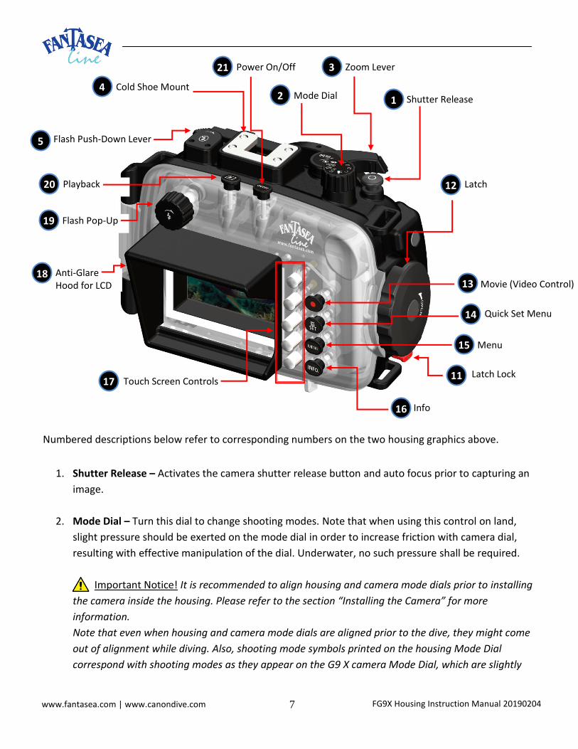
FG9X Housing Instruction Manual 20190204 7 www.fantasea.com | www.canondive.com
Numbered descriptions below refer to corresponding numbers on the two housing graphics above.
1. Shutter Release – Activates the camera shutter release button and auto focus prior to capturing an
image.
2. Mode Dial – Turn this dial to change shooting modes. Note that when using this control on land,
slight pressure should be exerted on the mode dial in order to increase friction with camera dial,
resulting with effective manipulation of the dial. Underwater, no such pressure shall be required.
Important Notice! It is recommended to align housing and camera mode dials prior to installing
the camera inside the housing. Please refer to the section “Installing the Camera” for more
information.
Note that even when housing and camera mode dials are aligned prior to the dive, they might come
out of alignment while diving. Also, shooting mode symbols printed on the housing Mode Dial
correspond with shooting modes as they appear on the G9 X camera Mode Dial, which are slightly
Flash Pop-Up
Movie (Video Control)
Menu
Latch
Latch Lock
19
Flash Push-Down Lever 5
Zoom Lever
Cold Shoe Mount
3
4 Mode Dial 2 Shutter Release 1
Playback 20
Power On/Off 21
Anti-Glare Hood for LCD
12
13
14 Quick Set Menu
15
11
Info 16
Touch Screen Controls 17
18

FG9X Housing Instruction Manual 20190204 8 www.fantasea.com | www.canondive.com
different than those featured on the G9 X Mark II camera. Therefore, always confirm selection of
proper shooting mode by referring to the LCD screen (top left corner).
3. Zoom Lever – Turning this control activates the camera zoom button.
a. In Shooting Mode – the zoom lever on the housing works in a reverse direction of the zoom
control on the camera. Confirm zoom direction and position by viewing the LCD screen:
i. Turn the zoom lever clockwise to zoom out, increasing the area visible in the frame.
ii. Turn the zoom lever counterclockwise to zoom in, so that the subject fills a larger
area of the frame and for close-up and macro images to be taken.
b. In Playback Mode - use the zoom lever as an index or playback lever.
4. Cold-Shoe Mount for Lighting Accessories- Enables mounting a flash, video light, torch, focus light or
action camera (like the GoPro) on top of the housing by using a dedicated connector. For further
information regarding such connectors, please visit the Fantasea website – www.fantasea.com
5. Flash Push-Down Lever – This lever allows blocking the camera built-in flash after it has been
popped-up by using the Flash Pop-Up switch.
a. In order to prevent the camera built-in flash from firing, apply slight downward pressure on
the Flash Push-Down lever and slide it rightwards until it sits securely in the small slot toward
the right side, as indicated by the arrow direction on top of the control. This pushes down
the camera built-in flash enough in order to prevent it from firing.
b. In order to release the camera built-in flash again, slide the Flash Push-Down lever leftwards
(towards hinge side of the housing) until it returns to its original position on the left. This will
enable the flash to pop-up again and to fire whenever activated.
6. Fiber Optic Cable Plate-
a. When installed on the housing, the fiber optic cable plate and the two adaptors inserted
inside it allow for an easy attachment of 2 fiber optic cables to the housing. For further
instructions, please refer to the section “External Flashes”.
b. Remove the fiber optic cable plate from the housing when using the camera’s internal flash
during your dive. In order to remove the plate, insert your fingers beneath the adaptors
installed inside the plate and pull the plate upwards till it is removed from its slot. Note that
when photographing using the camera built-in flash only, the flash diffuser accessory should
be installed, or else unwanted shading will occur in most images taken.
c. Make sure the fiber optic cable plate is secured to the housing by its secure line in order to
avoid losing it during the dive.

FG9X Housing Instruction Manual 20190204 9 www.fantasea.com | www.canondive.com
d. If using only one external flash, make sure the second fiber optic cable adaptor remains in its
place to block any light coming out of the exposed adaptor hole.
7. Mobile Connect - Rotating this control clockwise activates the camera Mobile Device Connection
button, thereby connecting the camera to a smart phone and allowing you to share your images.
8. Control Ring – Turning this control activates the control ring around the camera lens.
a. In shooting mode, the Control Ring can be used to adjust exposure settings (such as ISO
speed, Exposure Compensation, Shutter Speed and Aperture Value). To switch between the
function currently configured with the Control Ring, simply push the symbol on the
screen (Control Ring Function Switch) using the 2nd Touch Screen Control on the housing
(from the top).
b. If the symbol happens to be missing on the screen (Control Ring Function Switch) in
shooting mode, enter Menu Shooting Settings Page 2 Control Ring Settings
Switch with select “Enable”.
c. Alternatively, the Control Ring can be assigned to a commonly used setting by entering Menu
Shooting Settings Page 2 Control Ring Settings Switch with select
“Disable” Scroll down to Set Function select the requested function.
d. In playback mode, the Control Ring can be used in order to scroll between the images and
videos.
e. When entering camera menus, the Control Ring can be used to scroll between the different
items.
9. Lens Port - The housing lens port features a 67mm thread and it’s compatible with a wide variety of
“wet” accessory filters and lenses, including macro lenses, wide angle lenses and color correction
filters. In order to maintain the threads of the lens port, it is recommended to apply a small amount
of silicone grease to the threads on the housing port and on the accessory lens prior to installation.
For a selection of lens accessories available, visit the Fantasea website www.fantasea.com
10. 3 Trays Mounting Screw Holes – Enable mounting the housing on a tray, thereby allowing for the
addition of various image enhancement accessories to your underwater photo system. By choosing
any one of 3 adjustment positions, you can better determine how and where to position the housing
on the tray. This configuration also allows for the use of 2 set screws for the tray mount, thereby
preventing any swiveling of the housing on the tray.
11. Latch Lock (red lever) – This lock ensures the housing’s locking mechanism doesn’t accidently open
during the dive. For further instructions, please refer to the sections "Opening the Housing” and

FG9X Housing Instruction Manual 20190204 10 www.fantasea.com | www.canondive.com
“Closing the Housing”.
12. Latch – Once rotated and clicked into place, this latch ensures the housing is properly locked with a
watertight seal. For further instructions, please refer to the sections "Opening the Housing” and
“Closing the Housing”.
13. Movie (Video Control) –
a. To start recording a video, press the Movie control (red dot) in any shooting mode. The record
symbol (REC) appears and displayed with the elapsed time.
b. Push the Movie control again in order to stop recording.
c. If the Movie Control isn’t often made use of for recording videos, note that it can be assigned to
a different commonly used setting or function by entering Menu Shooting Settings Page 2
Set Video Button select the requested function.
14. Quick Set Menu – Pressing this control activates the Quick Set Menu button on the camera.
a. In shooting mode, push this control to enter the Quick Set Menu, which allows configuring
commonly used functions. Note that menu options and items vary depending on the
shooting mode.
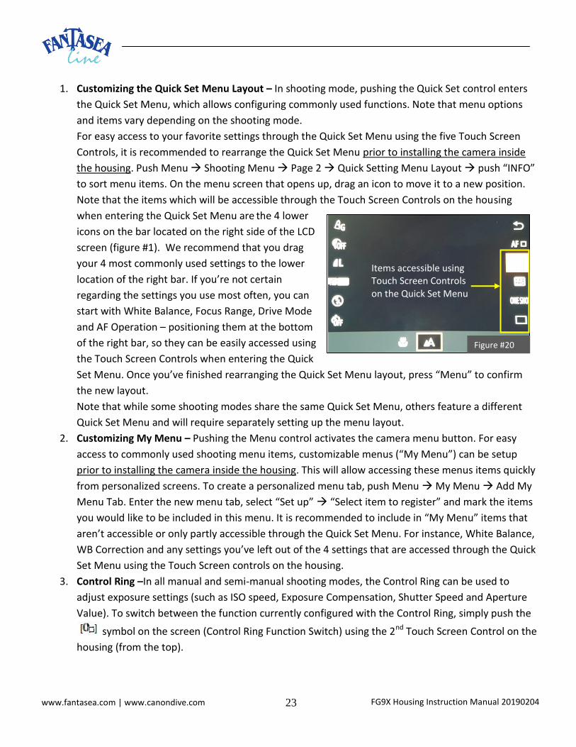
b. For easy access to your favorite settings through the Quick Set Menu using the five Touch
Screen Controls, it is recommended to rearrange the Quick Set Menu prior to installing the
camera inside the housing. In order to configure, push Menu Shooting Menu Page 2
Quick Setting Menu Layout push “INFO” to sort menu items. On the menu screen that
opens up, drag an icon to move it to a new position. Note that the items which will be
accessible through the Touch Screen
Controls on the housing when entering the
Quick Set Menu are the 4 lower icons on the
bar located on the right side of the LCD
screen (figure #1). We recommend that you
drag your 4 most commonly used settings to
the lower location of the right bar. If you’re
not certain regarding the settings you use
most often, you can start with White
Balance, Focus Range, Drive Mode and AF
Operation – positioning them at the bottom of the right bar, so they can be easily accessed
using the Touch Screen Controls when entering the Quick Set Menu. Once you’ve finished
rearranging the Quick Set Menu layout, press “Menu” to confirm the new layout.
Items accessible using Touch Screen Controls on the Quick Set Menu
Figure #1

FG9X Housing Instruction Manual 20190204 11 www.fantasea.com | www.canondive.com
c. Note that while some shooting modes share the same Quick Set Menu, others feature a
different Quick Set Menu and will require separately setting up the menu layout.
d. When entering camera menus, the Quick Set control can be used to confirm selections.
15. Menu - Pushing this control activates the camera menu button.
a. For easy access to commonly used shooting menu items, customizable menus (“My Menu”)
can be setup prior to installing the camera inside the housing. This will allow accessing these
menus items quickly from personalized screens.
b. To create a personalized menu tab, push Menu My Menu Add My Menu Tab. Enter the
new menu tab, select “Set up” “Select item to register” and mark the items you would like
to be included in this menu.
c. It is recommended to include in “My Menu” items that aren’t accessible or only partly
accessible through the Quick Set Menu. For instance, White Balance, WB Correction and any
settings you’ve left out of the 4 settings that are accessed through the Quick Set Menu using
the Touch Screen controls on the housing.
16. INFO – Pushing this control activates the INFO button on the camera.
a. In shooting mode, pushing the INFO button scrolls between the various information screens.
The information displayed once the INFO button is pushed in shooting mode can be
customized by pushing Menu Shooting Menu Page 1 Shooting information display.
b. In playback mode, pushing the INFO button scrolls between the various screens of
information provided for the previewed image or video file.
17. Touch-Screen Controls – The 5 Touch-Screen Controls were designed based on a new touch screen
technology and provide access to essential contact points on the camera touch screen. For useful
tips, recommended camera settings and helpful Touch Screen Controls guidelines, please refer to the
“Touch Screen Controls Friendly Guidelines” section.
Important Notice- If wearing gloves, Touch-Screen Controls will respond underwater, but will
respond in a dry environment only if the material the glove is made of is conductive.
18. Anti-Glare Hood for LCD - The anti-glare hood enables a better view of the LCD screen when shooting
in bright conditions. It can be removed and installed during the dive. For further instructions, refer to
the section “Preparing the Housing”. Note that the Anti-Glare Hood must be attached with a secure
line to the lower left housing loop (from back view) so it does not float away if mistakenly pulled off.
19. Flash Pop-Up - Turning this control counterclockwise pops up the camera built-in flash.
Note that once the camera built-in flash has been popped up, it can only be disabled by using the
Flash Push-Down Lever (no. 5) or through camera menus. Turning the Flash Pop-Up control clockwise

FG9X Housing Instruction Manual 20190204 12 www.fantasea.com | www.canondive.com
will not have any effect on the built-in flash.
20. Playback – Pushing this control activates the camera Playback button, allowing you to enter the
playback mode and to review images or videos stored on the memory card.
21. Power On/Off- Pushing this control activates the camera power switch button and turns the camera
on/off.

FG9X Housing Instruction Manual 20190204 13 www.fantasea.com | www.canondive.com
CANON POWERSHOT G9 X AND G9 X MARK II DIGITAL CAMERAS
Impressive image quality and stunning videos are produced by a camera that’s slim, fashionable and comfortable. The PowerShot G9 X and G9 X Mark II cameras are all this and more, featuring a 20.2 Megapixel, 1.0-inch High-Sensitivity CMOS sensor and a fast, f/2.0–4.9 lens that helps you capture inspiring images – even in deep water and low light – with detail and color to match. Subjects in the distance become closer with a 3x Optical Zoom lens (28–84mm equivalent). On the G9 X Mark II, a new DIGIC 7 image processor offers better autofocus performance, improved noise reduction at high ISOs and much faster continuous shooting performance, particularly when shooting RAW images. Movement can be captured in stunning Full HD video, or frozen in beautiful increments with up to 6.0 fps continuous shooting. At 1.0 inch, the image sensor on the PowerShot G9 X and G9 X Mark II cameras is larger than the ones on most other compact cameras. This allows it to capture a greater range of light, so bright areas of the image can be more detailed and less likely to be washed or blown out. With low-light scenes, like when diving in deep water, an ISO range of 125–12800 lets you use fast shutter speeds to help keep photos sharp and virtually unaffected by camera shake. The 20.2-Megapixel resolution is outstandingly high, giving you the option of printing out bigger photos or cropping in to highlight the best part. These two cameras are equipped with an intuitive and friendly user interface. Camera menus are customizable, meaning the settings you adjust frequently are easily accessible. The control ring allows making adjustments to various settings, simplifying the process even further.
Canon PowerShot G9 X and G9 X Mark II Highlights
1. 20.2 MP 1.0-inch high sensitivity CMOS sensor
2. Bright F2.0 28-84mm equiv. lens
3. 3x optical zoom
4. Minimum focus range of 2-inch
5. Wide ISO range of 125–12800
6. Full HD 1080p/60p video recording capabilities
7. 3.0-inch touch panel
8. Impressive range of creative shooting modes
9. Lightweight - only 7.37 ounces (209g)
10. Convenient control ring and mode dial for intuitive manual adjustment
11. ND (Neutral Density) filter for long exposure times and very wide apertures
12. NFC smartphone linking – Simple connectivity to smartphones via Wi-Fi

FG9X Housing Instruction Manual 20190204 14 www.fantasea.com | www.canondive.com
SETTING UP THE HOUSING
PREPARING THE CAMERA
1. Install a (preferably empty) memory card (16 GB+ capacity recommended) and a fully charged
battery inside the camera.
2. Remove the camera strap from the camera if one was installed.
3. Turn the Mode Dial so the Auto shooting mode is selected and aligned with the mark on the left
of the wheel. This will allow for the camera and housing mode dials to be aligned, so the housing
mode dial will indicate the proper mode selected by the camera dial.
4. It is recommended to program the camera to the most frequently used touch screen settings prior to installing the camera in the housing. Please refer to the “Touch Screen Controls Friendly Guidelines” section for further information.
PREPARING THE HOUSING
1. When using the housing for the first time-
a. Peel the transparent plastic screen protector off the back door exterior of the housing.
b. Install the hand lanyard on the housing by inserting it through the lanyard loop on the
bottom right of the housing (facing from back), then pulling it through itself and testing it
in order to make sure it is secure (figure #2 on the following page).
c. Install the housing side of the diffuser and lens port cover quick release secure lines by
tying them around the lower rectangular loops at the bottom of the housing (figure #3 on
the following page). Please note that these lines may come assembled and then there is
no need for installation.
d. Open the housing (see section “Opening the Housing” on the following page) and remove
the anti-glare hood out of the housing. Secure the anti-glare hood to the housing by tying
its secure string around the same loop – the lower rectangular loop at the bottom left
side of the housing.
Note
It is important that a first dive is always carried out with the housing
empty (no camera installed inside) in order to verify that the housing
watertight seal has not been affected during transport and after long
periods of storage.

FG9X Housing Instruction Manual 20190204 15 www.fantasea.com | www.canondive.com
e. Install the anti-glare hood over the anti-
glare hood rails at the back of the
housing. First install the anti-glare hood
over the top rail starting from the left
corner (figure #4), gently inserting it
between the top rail and the Flash Pop-
Up switch until it is properly seated on
the rail. Carefully stretch it to the right
so it is completely installed on the top
rail. Then stretch the anti-glare hood
downwards to install it on the bottom
rail, eventually making sure it’s sitting securely on both upper and lower rails. This can be
verified by looking at the housing from the left side and ensuring that the anti-glare hood
is close fitted to the housing with a noticeable space between the anti-glare hood and
the Flash Pop-Up switch on top of it (figure #5). Note that failure to properly install the
anti-glare hood on the top rail might result with inability to rotate the Flash Pop-Up
switch on top of the anti-glare hood.
Figure #2 Figure #3
Figure #4
Figure #5

FG9X Housing Instruction Manual 20190204 16 www.fantasea.com | www.canondive.com
f. If using a Hand Strap, install it on the two loops found at the right side of the housing.
Please refer to the section “Hand Strap” for further information.
g. It is important that a first dive with the housing is always made without the camera in
order to verify that the housing watertight seal has not been affected during transport
and after long periods of storage.
OPENING THE HOUSING
1. Pull the small red tab located at the bottom of the latch outwards (up and away from the
housing), as indicated by the arrow direction (figure #6). There is no need to apply any force.
2. While holding the latch lock up, turn the latch counterclockwise until the red latch tab is located
at the top of the latch and cannot be turned any further (figure #7). There is no need to apply
any force.
3. Carefully open the back side of the housing.
4. Note that when opening the housing for the first time or when opening it after airplane trips, increased resistance might be encountered. Therefore, it is important not to lock the housing and to leave it slightly open when transporting by air.
Figure #6 Figure #7

FG9X Housing Instruction Manual 20190204 17 www.fantasea.com | www.canondive.com
CHECKING THE O-RING
1. Prior to each closure of the housing, the back door black O-ring should be visually inspected. If there is any debris present, including dirt, sand, dust, hair or any other matter, it must be cleaned to ensure a proper watertight seal.
2. In order to clean the black O-ring, first remove it from the housing: a. Insert the O-ring remover between the black O-ring and the groove it is seated in (figure #8). b. Slip the tip of the inserted O-ring remover below the black O-ring, while making sure the O-
ring doesn’t get damaged (figure #9). c. Carefully hold the O-ring with your fingertips in order to remove it from the groove.
3. Cleaning the O-ring is a simple matter of wiping it with a damp, soft cloth to remove the foreign
matter. Be careful the cloth you use does not leave any of its own material behind as this can also
affect the effectiveness of the seal.
4. Apply a slight layer of silicone grease on the black O-ring. Please note that the amount of
lubrication required on the O-ring is only enough to allow it to slip into place without friction, so it
does not twist or become dislodged. More grease is not necessarily better, and in some cases might
interfere with the watertight seal of the housing. To avoid any damage caused to the O-ring by the
use of incompatible grease, it is recommended to apply only the silicone grease supplied by
Fantasea on the housing O-ring.
5. When reinstalling the O-ring, place it back into the groove starting at one corner and gently
pressing it into the groove all around the housing until it is all seated in the groove and no part of it
is sticking up or out of the groove.
6. The white O-ring featured on the back side of the front door should be visually inspected prior to
each dive. If there is any debris present, gently wipe the area with a soft cloth in order to cleanse it.
7. Silicone grease must NOT be applied on the white O-ring featured on the back side of the front
door. In addition, this white O-ring shouldn’t be removed unless it’s damaged.
Figure #8 Figure #9

FG9X Housing Instruction Manual 20190204 18 www.fantasea.com | www.canondive.com
INSTALLING THE CAMERA
Since the FG9X Housing is specifically designed for the Canon G9 X and G9 X Mark II digital cameras,
installing the camera in the housing is quite simple.
1. Make sure the camera is turned off.
2. Lift the housing Mode Dial so it doesn’t interfere with camera installation (figure #10).
3. Make sure that the Flash Push-Down Lever is raised and pulled all the way to the left.
4. Hold the camera parallel to the housing and then gently install it inside (figure #11). Avoid
inserting one side of the camera prior to the other, as this will make the installation difficult and
might cause damage to the camera or housing.
5. Take special care not to touch or damage the moisture detector device when installing the
camera. The Device is located inside the housing on the inner (right) side of the housing
interior to the latch (figure #12).
MOISTURE DETECTOR
Figure #10
Figure #12
Figure #11
MODE DIAL

FG9X Housing Instruction Manual 20190204 19 www.fantasea.com | www.canondive.com
6. Once the camera is inserted inside the housing, push the housing mode dial back down, so it
touches the camera mode dial.
7. If inserting a silica gel pack inside the housing in order to prevent moisture, it is best to insert it
on the left side of the camera, in the slot midway up between the two rubber shock absorber
mounts, where it doesn’t interfere with proper housing operation. It is important to make sure
that the silica gel pack doesn’t stick out, or else it might interfere with the watertight seal of the
housing.
CLOSING THE HOUSING
1. Turn the housing Mode Control Dial till the Auto
shooting mode symbol is positioned at the left
(figure #13). Make sure not to accidently turn this
control any further before closing the housing.
2. Turn the latch so that the small red tab located on
the latch is pointed towards the front side of the
housing (figure #14).
3. Carefully close the back door of the housing, pushing it against the front door, while making sure
there is nothing sticking out of the housing or impairing the smooth closure of the back door.
Then firmly press the back door against the forward section of the housing.
4. Turn the latch clockwise until the latch clicks. The small red tab should then be pointed towards
the bottom of the housing (figure #15).
Figure #13
Figure #14 Figure #15
AUTO
FG9X Housing Instruction Manual 20190204 20 www.fantasea.com | www.canondive.com
5. Gently try pulling the back door away from the front door. If the housing is properly closed, it should
be impossible to open the back door. 6. Visually inspect the black O-ring through the transparent back door for proper closure. Make
sure it isn’t twisted or out of the groove and that no foreign matter has been caught in the seal,
such as secure lines, sand, grit, hairs or any other foreign substance.
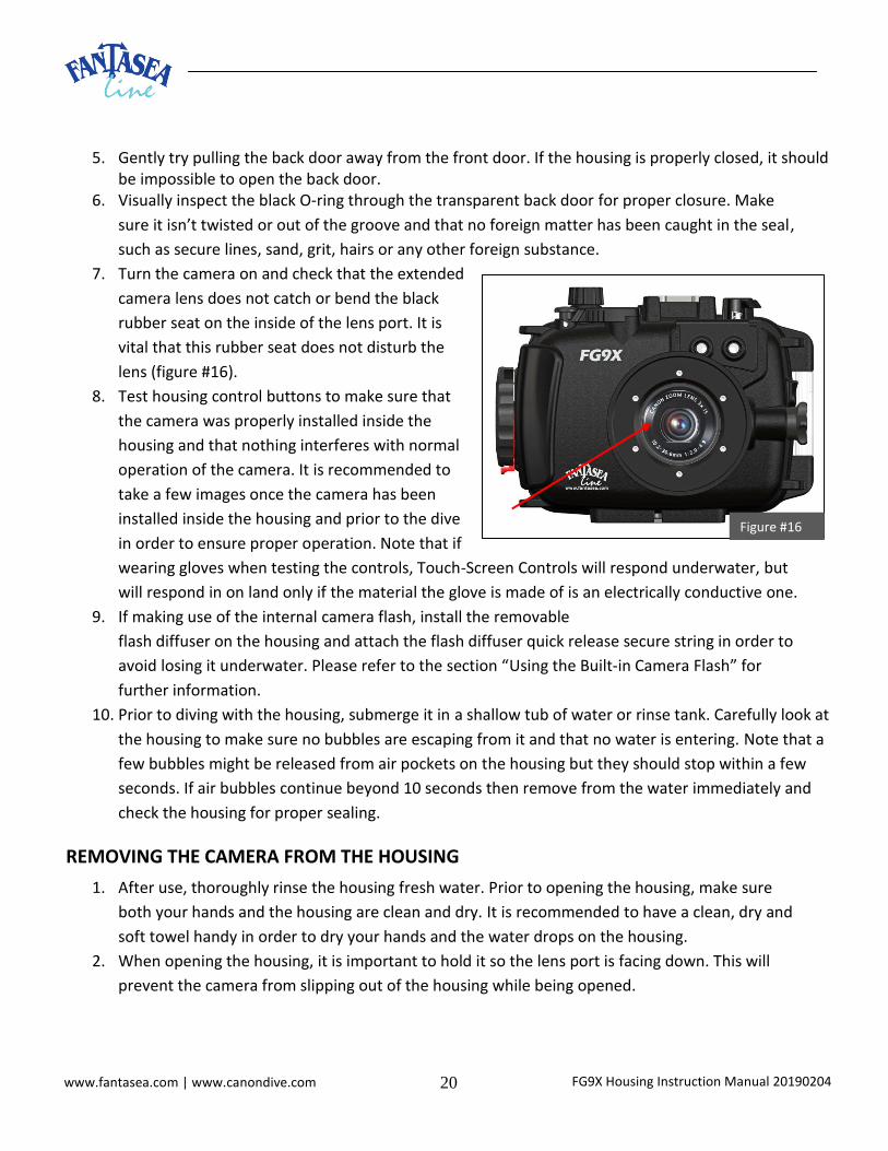
7. Turn the camera on and check that the extended
camera lens does not catch or bend the black
rubber seat on the inside of the lens port. It is
vital that this rubber seat does not disturb the
lens (figure #16).
8. Test housing control buttons to make sure that
the camera was properly installed inside the
housing and that nothing interferes with normal
operation of the camera. It is recommended to
take a few images once the camera has been
installed inside the housing and prior to the dive
in order to ensure proper operation. Note that if
wearing gloves when testing the controls, Touch-Screen Controls will respond underwater, but
will respond in on land only if the material the glove is made of is an electrically conductive one.
9. If making use of the internal camera flash, install the removable
flash diffuser on the housing and attach the flash diffuser quick release secure string in order to
avoid losing it underwater. Please refer to the section “Using the Built-in Camera Flash” for
further information.
10. Prior to diving with the housing, submerge it in a shallow tub of water or rinse tank. Carefully look at
the housing to make sure no bubbles are escaping from it and that no water is entering. Note that a
few bubbles might be released from air pockets on the housing but they should stop within a few
seconds. If air bubbles continue beyond 10 seconds then remove from the water immediately and
check the housing for proper sealing.
REMOVING THE CAMERA FROM THE HOUSING
1. After use, thoroughly rinse the housing fresh water. Prior to opening the housing, make sure
both your hands and the housing are clean and dry. It is recommended to have a clean, dry and
soft towel handy in order to dry your hands and the water drops on the housing.
2. When opening the housing, it is important to hold it so the lens port is facing down. This will
prevent the camera from slipping out of the housing while being opened.
Figure #16

FG9X Housing Instruction Manual 20190204 21 www.fantasea.com | www.canondive.com
3. Open the housing as described in the section “Opening the Housing” and carefully remove the
camera from the housing. Take sufficient care that no water drips from your hair and body onto
the housing and camera.
USING THE CAMERA BUILT-IN FLASH
1. The Canon G9 X and G9 X Mark II have a built-in flash capable of illuminating nearby underwater
subjects. For stronger lighting, illuminating subjects that are farther away, avoiding backscatter,
eliminating shadowing effects and photographing in deep water, an accessory slave flash is
recommended. For further information, please refer to the section “External Flashes”.
2. In order to make use of the built-in camera flash, remove the Fiber Optic Cable Plate from the
housing. Insert your fingers beneath the adaptors installed inside the plate and push the plate
upwards till it is removed from its slot. Make sure the fiber optic cable plate is secured to the
housing by the dedicated secure line in order to avoid losing it during the dive.
3. The removable flash diffuser included assists with softening the built-in flash output, increasing its
angle of coverage and decreasing the amount of backscatter in the images (the unattractive
snowstorm effect of the flash reflecting off suspended particles in the water).
a. In order to install the removable flash
diffuser, hold the diffuser against the
housing lens port so it is inserted inside
the dedicated rail around the lens port
and pointed towards the top left corner
of the housing (facing from back) at a 45-
degree angle (figure #17).
b. Turn the diffuser counterclockwise
around the lens port until it reaches a
proper vertical position and clicks (figure
#18).
c. Attach the flash diffuser quick release
secure string to the other side of the
string connected to the housing in order
to avoid losing the flash diffuser
underwater.
d. In order to remove the flash diffuser from
the housing, gently pull it towards the top
left corner of the housing at a 45-degree
angle until it snaps out of place.
Figure #17
Figure #18

FG9X Housing Instruction Manual 20190204 22 www.fantasea.com | www.canondive.com
e. During the dive, in order to disable the flash diffuser, the diffuser can be turned clockwise
around the lens port until it reaches a horizontal position and clicks (figure #19 below). This
rest-point of the diffuser eliminates the need to completely remove it from the housing during
the dive.
4. It is best to set the camera flash mode to “Flash
Always” as artificial light is required in most
compositions for the purpose of color and light
reproduction. This will ensure the built-in camera
flash fires on every image taken regardless of
ambient light available. Please refer to the Canon
G9 X or G9 X Mark II instruction manual for
further instructions regarding such settings.
5. Turn the Flash Pop-Up dial counterclockwise in
order to pop up the camera built-in flash.
6. Note that once the camera built-in flash has been
popped up, it can be disabled again using the Flash
Push-Down Lever or through camera menus.
Turning the Flash Pop-Up control clockwise will not have any effect on the built-in flash.
7. To use the Flash Push-Down Lever in order to disable the camera built-in flash once it has been
popped up, apply slight downward pressure on the lever and slide it rightwards until it sits securely
in the small slot toward the right side, as indicated by the arrow direction on top of the control. This
pushes down the camera built-in flash enough in order to prevent it from firing.
8. In order to release the camera built-in flash again, slide the Flash Push-Down lever leftwards
until it returns to its original position on the left. This will enable the flash to pop-up again and to
fire whenever activated.
TOUCH SCREEN CONTROLS FRIENDLY GUIDELINES
The FG9X Housing features 5 silvery Touch-Screen Controls on the back door, designed based on a new
touch screen technology. These controls provide access to essential contact points on the right side of the
camera LCD touch screen. Below you will find a few useful tips, recommended camera settings and helpful
guidelines for enhancing camera functions accessibility using the dedicated Touch-Screen Controls.
Figure #19
Important Notice
This section refers to certain camera functions and settings which can be easily accessed using housing
Touch-Screen Controls following simple camera menu configurations.
Note that almost all other camera functions, even if not mentioned below, can still be accessed through
the housing, either by Touch Screen Controls or through camera menus.
FG9X Housing Instruction Manual 20190204 23 www.fantasea.com | www.canondive.com
1. Customizing the Quick Set Menu Layout – In shooting mode, pushing the Quick Set control enters
the Quick Set Menu, which allows configuring commonly used functions. Note that menu options
and items vary depending on the shooting mode.
For easy access to your favorite settings through the Quick Set Menu using the five Touch Screen
Controls, it is recommended to rearrange the Quick Set Menu prior to installing the camera inside
the housing. Push Menu Shooting Menu Page 2 Quick Setting Menu Layout push “INFO”
to sort menu items. On the menu screen that opens up, drag an icon to move it to a new position.
Note that the items which will be accessible through the Touch Screen Controls on the housing
when entering the Quick Set Menu are the 4 lower
icons on the bar located on the right side of the LCD
screen (figure #1). We recommend that you drag
your 4 most commonly used settings to the lower
location of the right bar. If you’re not certain
regarding the settings you use most often, you can
start with White Balance, Focus Range, Drive Mode
and AF Operation – positioning them at the bottom
of the right bar, so they can be easily accessed using
the Touch Screen Controls when entering the Quick
Set Menu. Once you’ve finished rearranging the Quick Set Menu layout, press “Menu” to confirm
the new layout.
Note that while some shooting modes share the same Quick Set Menu, others feature a different
Quick Set Menu and will require separately setting up the menu layout.
2. Customizing My Menu – Pushing the Menu control activates the camera menu button. For easy
access to commonly used shooting menu items, customizable menus (“My Menu”) can be setup
prior to installing the camera inside the housing. This will allow accessing these menus items quickly
from personalized screens. To create a personalized menu tab, push Menu My Menu Add My
Menu Tab. Enter the new menu tab, select “Set up” “Select item to register” and mark the items
you would like to be included in this menu. It is recommended to include in “My Menu” items that
aren’t accessible or only partly accessible through the Quick Set Menu. For instance, White Balance,
WB Correction and any settings you’ve left out of the 4 settings that are accessed through the Quick
Set Menu using the Touch Screen controls on the housing.
3. Control Ring –In all manual and semi-manual shooting modes, the Control Ring can be used to
adjust exposure settings (such as ISO speed, Exposure Compensation, Shutter Speed and Aperture
Value). To switch between the function currently configured with the Control Ring, simply push the
symbol on the screen (Control Ring Function Switch) using the 2nd Touch Screen Control on the
housing (from the top).
Items accessible using Touch Screen Controls on the Quick Set Menu
Figure #20

FG9X Housing Instruction Manual 20190204 24 www.fantasea.com | www.canondive.com
If the symbol happens to be missing on the screen (Control Ring Function Switch) in shooting
mode, enter Menu Shooting Settings Page 2 Control Ring Settings Switch with
select “Enable”.
4. White Balance –
The following guideline is only relevant if you choose to include White Balance in the 4 items
available through the Quick Set Menu using Touch Screen Controls (see section #1- “Customizing the
Quick Set Menu Layout”).
In most Quick Set Menu items, once an item (setting type) is selected, rotating the control ring
scrolls between the various options available for this setting. However, in most shooting modes,
when selecting White Balance through the Quick Set Menu using Touch Screen Controls, rotating
the Control Ring does not allow scrolling between the various white balance modes available on this
camera. Instead, rotating the Control Ring in this case only manually corrects white balance
temperature. There are a few methods to adapt in order to have full control and access to this
setting:
o Prior to installing the camera inside the housing, enter the white balance item through the
Quick Set Menu and use the touch screen to select the white balance mode you’re most
likely to be working with underwater. The camera “saves” this mode as the default one and
displays this mode first whenever entering the White Balance item on the Quick Set Menu,
even if the camera is turned off and on again. During the dive, selecting White Balance on
the Quick Set Menu using Touch Screen Controls will automatically select the white balance
mode you’ve set prior to the dive, thereby providing you with easy access to your preferred
white balance mode. Note that while some shooting modes share the same default settings,
others feature different ones and will require separately setting up the default white balance
mode.
o In case a different white balance mode is requested during the dive (rather than the initial
white balance mode set up as the default one prior to installing the camera inside the
housing), it can be selected through the camera main menu. Push Menu Shooting Menu
Page 6 White Balance. Once the white balance menu has been entered, rotating the
Control Ring allows scrolling between the various modes available. Note that once a new
mode is selected, it also becomes the default one when entering the White Balance item on
the Quick Set Menu.
o White Balance advanced manual (color temperature) adjustment can be accessed by pushing
the Menu once a mode is selected inside the white balance item on the Quick Set Menu. Use
the control ring in order to shift the colors horizontally (between A and B) and use the two
top Touch Screen Controls in order to shift the colors vertically (between G and M).
5. Manual Focus – In most shooting modes, a Focus Mode icon (AF/MF) appears on the right bar.
When this icon is pushed using the 4th Touch Screen Control (from the top), it shifts between Auto

FG9X Housing Instruction Manual 20190204 25 www.fantasea.com | www.canondive.com
Focus (AF) and Manual Focus (MF). When shifting to Auto Focus, no further menus open up, as the
camera simply activates its automatic focus algorithm. When shifting to Manual Focus, a control bar
shows up on the screen, allowing for manual focus adjustment. Although it might seem as if Touch
Screen Controls can be used to access the arrows adjusting the focus on the right side of the control
bar, these arrows cannot be accessed using the housing Touch Screen Controls. Instead, manual
focus adjustment can be made on the control bar using the Control Ring. To return to Auto Focus
mode, push the Quick Menu Set control to exit the control bar display and then use the 4th Touch
Screen Control from the top again to select “Auto Focus”.
When recording videos, manual focus can be adjusted using the Control Ring prior to capturing the
video or using Touch Screen Controls during video recording.
6. Flash Mode - In manual shooting modes, when selecting Flash Mode through the Quick Set Menu
using Touch Screen Controls, rotating the Control Ring does not allow scrolling between the various
flash modes available on this shooting mode. Instead, rotating the Control Ring in this case only
adjusts flash compensation. There are two alternative ways in which flash mode can be selected
and accessed in these shooting modes:
o Enter the Quick Set Menu and select the item Flash Mode using Touch Screen Controls
(assuming that Flash Mode is one of the items positioned at the bottom of the right Quick
Set Menu bar and can be accessed using one of the Touch Screen Controls). Once the Flash
Mode item has been entered, press Menu Flash Firing. Rotating the Control Ring allows
scrolling between the various modes available in this particular shooting mode.
o The requested flash mode can be selected through the camera main menu. Push Menu
Shooting Menu Page 5 Flash Settings Flash Firing. Rotating the Control Ring allows
scrolling between the various modes available in this particular shooting mode.
o Note that once a new flash mode is selected, it also becomes the default one when entering
the Flash Mode item on the Quick Set Menu.
7. Picture Style – On the G9 X Mark II camera (only), the Quick Menu includes an item called “Picture
Style”. If making use of this item during the dive and including it as one of the items accessible
through the housing (on the right column of the Quick Menu), note that some settings might require
advance setup (prior to installing the camera inside the housing). While scrolling through the styles
and making a selection is possible through housing controls, advanced settings for each style
(available through the “INFO” button), might not be fully accessible through housing controls and
therefore frequently used attributes should be set ahead for these styles.
Note On the G9 X Mark II, camera notifications occasionally appear on the
screen and must be cleared in order to continue using the camera. When
camera is installed inside the housing, these notifications can be cleared
by activating the camera zoom control.

FG9X Housing Instruction Manual 20190204 26 www.fantasea.com | www.canondive.com
OPTIONAL ACCESSORIES
For the full selection of Fantasea accessories compatible with the FG9X Housing, please refer to the
Fantasea website – WWW.FANTASEA.COM
EXTERNAL FLASHES
Underwater flashes and strobes were designed to improve the color, lighting and quality of your
underwater images. Since light and color are absorbed by water, using an external flash is recommended in
all depths, during daylight and night dives. In addition to retrieving the color and light absorbed by water,
underwater flashes also allow for creative lighting, assist in reducing the amount of backscatter and prevent
the shadowing effect caused by the housing lens port when using the built-in camera flash, especially when
accessory lenses are mounted on the housing.
The FG9X Housing can be used with underwater slave flashes. These external flashes feature a slave sensor
which triggers the external flash to fire in sync with the internal camera flash.
Most underwater slave strobes are capable of synchronizing with the internal camera flash without any
cables under certain diving conditions. They feature a slave sensor that triggers the strobe to fire in sync
with the camera built-in flash as long as the strobe and the camera are positioned on the same axis and as
long as there is not much ambient light available. However, if the strobe slave sensor isn’t pointed directly
at the internal camera flash, or when photographing during daylight, in clear water and bright conditions,
the slave sensor might fail recognizing the output of the internal camera flash. Connecting a fiber optic
cable between the internal camera flash and the slave strobe ensures full synchronization in all angles and
diving conditions.
Attaching Fiber Optic Cables to the Housing
o When installed on the housing, the fiber optic cable plate and the two adaptors inserted inside it
allow for an easy attachment of up to 2 fiber optic
cables to the housing.
o If the fiber optic cable you have features a different
type of adaptor, remove this adaptor from the end of
the cable and use the adaptors included with the FG9X
Housing instead.
o Remove the Fiber Optic Cable Plate from the housing.
Insert your fingers beneath the adaptors installed
inside the plate and push the plate upwards till it is
removed from its slot.
Figure #21

FG9X Housing Instruction Manual 20190204 27 www.fantasea.com | www.canondive.com
o Prior to installing the fiber optic cable on the Fiber Optic Cable Plate, make sure that the two black
adaptors are firmly and properly installed inside the plate (figure #21 on the previous page).
o Insert the exposed end of the fiber optic cable into the small hole of the adaptor unit, starting from
the end that features a screw and pushing it towards the end that features an O-ring (figure #22),
until the fiber optic cable reaches the end of the adaptor, which can be verified by looking from the
other side of the Fiber Optic Cable Plate. The fiber optic cable should be extending out no more
than 1mm (figure #23).
o Use the screwdriver included in order to tighten the screw on the adaptor (figure #24). Tighten it
enough to stabilize the fiber optic cable inside the adaptor, but don't tighten it too strongly.
Tightening the screw too much might damage the fiber
optic cable.
O Once the fiber optic cable has been installed on the
Fiber Optic Cable Plate, install the Fiber Optic Cable
Plate by inserting it inside the dedicated slot on the
housing and pushing it all the way in. o When installed on the housing, the Fiber Optic Cable
Plate blocks the internal camera flash, so only the
external slave flash illuminates the subject. This
diminishes the effects of backscatter, as well as
eliminates any shadowing effect caused by housing lens
port, especially when lens accessories are mounted on
the housing.
8. Follow the instructions in your strobe manual on how to
synchronize your camera with the external strobe and to
select the proper pre-flash program for your camera. It is
recommended to test the synchronization when
photographing opposite a mirror. In this case, the output
of both the built-in camera flash and the strobe should
be visible in the test shot taken.
9. When attaching Sea&Sea fiber optic cables to the
housing, housing adaptors should first be removed off
the fiber optic cable plate. This can be done by gently
pulling them out from the front side of the plate, using
the aid of a small needle nose set of pliers. Make sure
not to damage the fiber optic cable. It’s recommended
to apply some silicone grease on the small o-rings of
these adaptors, so they can be installed and removed
Figure #22
Figure #23
Figure #24

FG9X Housing Instruction Manual 20190204 28 www.fantasea.com | www.canondive.com
more easily. Sea&Sea fiber optic cables feature an adaptor that fits right inside the fiber optic cable
plate. Simply push the adaptor featured at the end of the cable into the dedicated slots on the front
side of the plate, instead of the adaptors you’ve just pulled out, till they are fully fitted inside. Gently
pull the fiber optic cable in order to make sure that it doesn’t come off easily.
FLASH & VIDEO LIGHTING SETS
A variety of Fantasea flash and video lighting sets are available for the FG9X Housing, enabling you to
further enhance your images and videos. These sets include trays, Flex arms, slave flashes, powerful and
sturdy yet stylish video lights, fiber optic cables, focus lights, padded bags and more.
LENS ACCESSORIES
The FG9X Housing lens port features a 67mm thread which can accommodate all 67mm conversion lenses
and color correction filters, such as:
10. Optical Wide Angle Wet Lenses: Wide angle lenses allowing for high quality wide angle images up to
14mm.
11. BigEye Wide Angle Lenses: Perfect for shooting seascape, divers, ship wrecks and schools of fish,
without moving further away from the subject, thereby still taking full advantage of water clarity
and artificial light sources.
12. SharpEye Macro Lenses: Perfect for shooting close-up images of fish, corals, textures and more.
These macro lenses magnify the subject and enable the camera to focus on short distances for
creating super sharp images.
13. RedEye & PinkEye Color Correction Filters: Used to restore the colors absorbed by the water. In
shallow depths, these filters can serve as an attractive alternative to artificial light sources. These
filters can be mounted directly on the housing lens port, and can also be installed inside BigEye and
SharpEye accessory lenses.
14. EyeGrabber Lens Holders: Attach to Flex or Ball & Joint arms, enabling safe, secure and easily
accessible storage for your lens accessories when not in use during the dive.
Important Notice
In order to maintain the threads on the lens port, it is recommended to apply a small amount of silicone
grease to the threads on the housing port and on the accessory lens prior to installation.
COLD-SHOE CONNECTOR FOR LIGHTING ACCESSORIES
The Cold-Shoe Mount featured on the housing enables mounting a flash, video light, night dive torch or
focus light on top of the housing by using a standard Cold-Shoe connector mount.
FG9X Housing Instruction Manual 20190204 29 www.fantasea.com | www.canondive.com
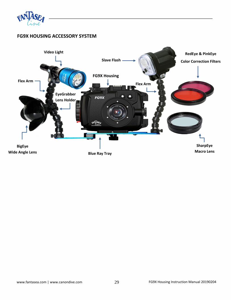
FG9X HOUSING ACCESSORY SYSTEM
Slave Flash
Flex Arm
SharpEye
Macro Lens
FG9X Housing
Video Light
Flex Arm
BigEye
Wide Angle Lens
EyeGrabber
Lens Holder
Blue Ray Tray
RedEye & PinkEye
Color Correction Filters
Flex Arm

FG9X Housing Instruction Manual 20190204 30 www.fantasea.com | www.canondive.com
HOUSING HAND GRIP STRAP
The FG9X Housing features two hand strap loops on the “latch” side of the housing, which enable the
attachment of an optional hand grip strap for the housing in order to improve hand grip, especially when
using the housing during extreme sports activities.
Installing the Fantasea Hand Strap (Cat. No. 11188) on the Housing
1. Pull the narrow nylon Velcro strip through top of lower housing ring (below the locking latch) in a
downward direction to the end of the strip (figure #25 and #26).
2. Place the wide flat Velcro mid-section over the locking latch and pull the thin Velcro strip over the top
of this mid-section and through the upper housing ring from bottom to top all the way through (figure
#27).
3. Double back the thin nylon Velcro strip and secure it tight to the top of the Velcro strip previously
inserted (same strip) and press down. Then cover with the wide flap (should be on the right side) over
the thin Velcro strips (figure #28).
Figure #25 Figure #26
Figure #27
Figure #28

FG9X Housing Instruction Manual 20190204 31 www.fantasea.com | www.canondive.com
4. Place top flap (with logo) over bottom flap and press to close (figures #29 and #30).
5. To use, slide right hand from back side to front of the Hand Strap with knuckles protruding slightly out
of the front (lens side) of the strap (figure #29). Have it snug but not too tight, to allow for control
manipulation.
6. Always use the wrist lanyard with the hand strap.
7. When opening or closing the housing, you may need to loosen the Hand Strap slightly in
order to rotate it forward to allow for easier opening and closing of the latch.
8. When closing the housing, take special notice and care not to close part of the Hand Strap
inside the housing, which will interfere with the watertight seal of the housing.
9. Make sure to rinse the Hand Strap in fresh water and then dry after every use. Store in a dry,
shaded area.
FANTASEA MOISTURE DETECTOR
Note!
Never soak or wash the interior of the housing with water. This will set off the alarm in a way that cannot be disabled, eventually causing irreparable damage to the electronic unit!
The moisture detector is a bonus add-on component and not an integral part of the housing. Accordingly, it is not part of the housing warranty coverage. The moisture detector has no warranty coverage.
Figure #29 Figure #30
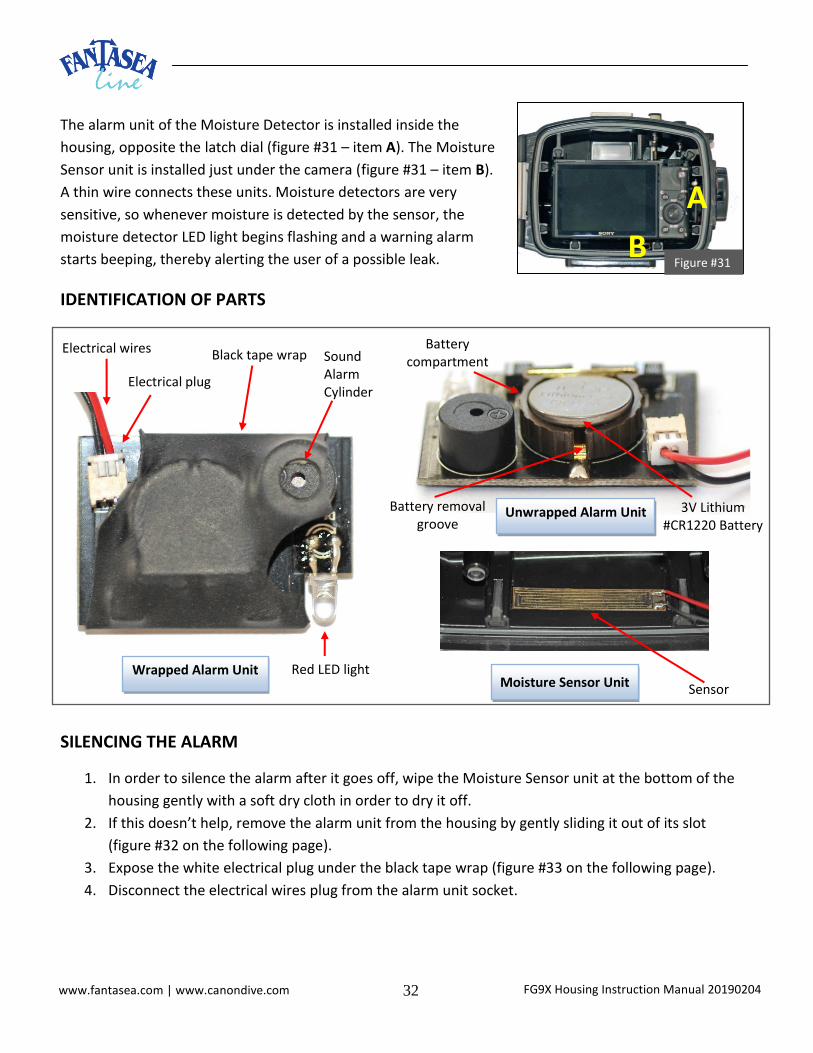
FG9X Housing Instruction Manual 20190204 32 www.fantasea.com | www.canondive.com
The alarm unit of the Moisture Detector is installed inside the
housing, opposite the latch dial (figure #31 – item A). The Moisture
Sensor unit is installed just under the camera (figure #31 – item B).
A thin wire connects these units. Moisture detectors are very
sensitive, so whenever moisture is detected by the sensor, the
moisture detector LED light begins flashing and a warning alarm
starts beeping, thereby alerting the user of a possible leak.
IDENTIFICATION OF PARTS
SILENCING THE ALARM
1. In order to silence the alarm after it goes off, wipe the Moisture Sensor unit at the bottom of the
housing gently with a soft dry cloth in order to dry it off.
2. If this doesn’t help, remove the alarm unit from the housing by gently sliding it out of its slot
(figure #32 on the following page).
3. Expose the white electrical plug under the black tape wrap (figure #33 on the following page).
4. Disconnect the electrical wires plug from the alarm unit socket.
Figure #31
Electrical wires
Electrical plug
Black tape wrap Sound Alarm Cylinder
Red LED light
Battery compartment
Wrapped Alarm Unit
Unwrapped Alarm Unit 3V Lithium #CR1220 Battery
Battery removal groove
Moisture Sensor Unit Sensor
A
B

FG9X Housing Instruction Manual 20190204 33 www.fantasea.com | www.canondive.com
REPLACING BATTERIES
1. Remove the alarm unit from the housing by gently sliding it
out of its slot (figure #32).
2. Disconnect the electrical wires plug from the unit socket
(figure #33).
3. Peel the black tape wrapped around the Alarm unit by gently
cutting it with a utility knife (figure #34). Make sure that the
knife doesn’t come in contact with the unit under
the tape and that you only cut the tape.
4. Remove the old battery by lifting it with a small
screwdriver through the battery removal groove
(figure #35).
5. Prepare a new 3V Lithium #CR1220 battery, widely
available at any hardware store or watch repair
shop.
6. IMPORTANT! The battery should be installed with
the “+” symbol facing up and out of the unit!
7. Gently push the new battery it into the battery compartment and make sure it doesn’t fall off
easily.
WARNING Install only 3V Lithium #CR1220 batteries inside the Moisture Alarm unit. Using any other type
of batteries will cause irreparable damage to the electrical unit. 8. To secure the battery and make sure it doesn’t fall out of place, wrap the battery compartment
area with a small piece of electrical tape. Be careful not to cover the round cylinder which
Figure #32 Figure #33
Figure #34
Figure #35

FG9X Housing Instruction Manual 20190204 34 www.fantasea.com | www.canondive.com
produces the alarm sound. Alternatively, you can wrap the whole alarm unit with tape and then
make a hole over the alarm cylinder (figure #36).
9. Insert the electrical wires plug back into the alarm unit socket.
10. Slide the alarm unit back into the dedicated slot inside the housing, opposite the buckle. Make
sure to install the unit with the round alarm cylinder facing the housing interior and the LED
pointing outwards, to the back of the housing (figure #37).
11. You can test the Moisture Detector by placing a wet finger over the moisture sensor unit at the
bottom of the housing. Once you have confirmed that the alarm is working, gently dry off the
moisture sensor unit. This should silence the alarm.
REPLACING THE ALARM UNIT
1. Remove the alarm unit from the housing by gently sliding it out of its slot (figure #32 on the
previous page).
2. Expose the white electrical plug under the black tape wrap (figure #33 on the previous page).
3. Disconnect the electrical wires plug from the alarm unit socket.
4. Connect the electrical wires plug to the socket of a new alarm unit.
5. Slide the alarm unit back into the dedicated slot inside the housing, opposite the buckle. Make
sure to install the alarm unit with the round alarm cylinder facing the housing interior and the
LED pointing outwards, to the back of the housing (figure #37 on the previous page).
6. You can test the Moisture Detector by placing a wet finger over the moisture sensor unit at the
bottom of the housing. Once you have confirmed that the alarm is working, gently dry off the
moisture sensor unit. This should silence the alarm.
Figure #36 Figure #37

FG9X Housing Instruction Manual 20190204 35 www.fantasea.com | www.canondive.com
CARE & MAINTENANCE
The Fantasea FG9X Housing requires only a minimum amount of care for safe and reliable performance. The following tips will enable you to get the best results:
1. Always rinse your housing in streaming fresh water and if possible soak the housing in a fresh water tub or rinse tank for about 20 minutes after every dive in order to dissolve the salt water crystals from around the controls and openings of the housing. Manipulate each of the movable controls to assist the removal of salt particles from these tight areas.
2. Allow the housing to dry thoroughly before packing away for the day or for the trip home. You may use a soft towel or cloth to dry the housing. Be sure there is no grease or other debris on the towel.
3. Visually check the condition of the black O-ring before every dive. If it is dirty, clean it with fresh water and dry it with a soft cloth as described throughout the manual. If it is damaged in any way, such as cut or perforated, replace it before using the housing again.
4. It is recommended to slightly lubricate the black O-ring periodically. It's important to note that the amount of lubrication required on the O-ring is only enough to allow it to slip into place without friction, so it does not twist or become dislodged. More grease is not necessarily better, and in some cases might interfere with the housing watertight seal.
5. Use only the supplied silicone grease for lubricating the back door black O-ring. Use of any other grease might impair the watertight seal of the housing.
6. Avoid removing the white O-ring featured on the back side of the front door unless it’s damaged. 7. Be careful not to get greasy fingerprints or dirt on the lens port. This will affect the image quality.
Wipe any dirt or grease off with fresh water and a soft cloth. 8. Never handle the housing with your hands coated in suntan, oil or cream. Avoid getting any oils, creams
or petrol-related substances or liquids on the housing surface, as this can distort and damage the housing materials.
9. Do not drop the housing on hard surfaces, it could crack and its watertight seal might be damaged.
10. Do not disassemble or modify the housing, as this may cause leaks. 11. Do not leave the housing in direct sunlight, inside a car in hot weather, or near a heater. Heat
may warp the housing and cause leaks. If you have to leave the housing in the sun, it is important to cover it with a towel.
12. Travel with the housing protected in a padded case. It is best to remove the camera from inside the housing when traveling and to provide it with its own protective case or compartment.
13. Always leave the housing slightly open when transporting by air. 14. Never dive with the Fantasea FG9X Housing to a depth greater than 60 meters/200 feet. 15. It is important to carry out the first dive without the camera inside the housing. Check that the
watertight seal has not been affected during transport and long periods of storage. 16. It is likewise recommended to visually monitor the housing during every descent, especially for
the first 10 meters/33 feet. If water is observed entering the housing or bubbles escaping from it, the housing should be rotated to a port down position and held that way as you return to the surface immediately and get it out of the water.

FG9X Housing Instruction Manual 20190204 36 www.fantasea.com | www.canondive.com
17. When mounting wet lenses on the housing lens port, it is recommended to follow the guidelines below in order to avoid wearing out the threads of the housing lens port and lenses over time:
a. Prior to installing the lens on the housing, it is recommended to apply a small amount of silicone grease on the threaded area of the lens (and adaptor, if used) to reduce the amount of friction.
b. Install the lens on the housing lens port underwater only and remove it prior to ending the dive. Once removed, the lens can be mounted on a lens holder. Avoid having the lens assembled on the housing on land as much as possible, as it is heavier and exerts more pressure on the threads.
c. It is recommended to reduce wearing of the threads by using lens mounting accessories such as bayonet mounts or flip adaptors.
d. These guidelines apply to all wet lenses brands and models, but especially important when making use of relatively heavy wet lenses.
FANTASEA PRODUCT CONSUMER LIMITED WARRANTY
“Fantasea” warrants this Fantasea Line branded product against defects in materials and workmanship under reasonable use for a period of ONE (1) YEAR, (two years, where required by law as determined by the origin of the authorized dealer). This warranty is effective from the date of retail purchase from Fantasea or an authorized Fantasea dealer, by the original end-user purchaser (“Warranty Period”). This warranty does not cover any commercial use of the product. If a product defect arises and a valid claim is received within the Warranty Period, at its option, Fantasea, or its authorized service facilities will either (1) repair the product defect at no charge, (2) exchange the product with a product that is new or which has been manufactured from new or serviceable used parts and is at least functionally equivalent to the original product. The warranty will not extend beyond the original warranty period. Your Fantasea Product should be registered within 30 days of purchase. You must keep the proof of purchase which indicates the date on which the purchase was made; as you may be required to show proof of purchase if you need warranty service. The following conditions apply: 1. This warranty extends to the original purchaser only. It is not assignable or transferable. 2. The warranty does not cover damage resulting from misuse, abuse, negligence, or accidents. Proper maintenance of the Product is the responsibility of the owner. 3. The warranty does not cover damage directly or indirectly resulting from the use of unauthorized replacement parts or service performed by unauthorized facilities. 4. This warranty does not cover any damage to any other product used in conjunction with the Fantasea product, including cameras and lenses, and resulting from any defect in the product materials or workmanship. 5. The cost of sending the product back to Fantasea or its authorized service facilities is the responsibility of the customer. 6. The warranty does not cover any incidental damages resulting from any defects in the product. This expressly includes any travel reimbursements or any other costs associated with the purchaser’s optional use of the product. The conditions of this warranty are expressly in lieu of all other expressed warranties, including the payment of consequential or incidental damages for the breach of any warranty. Please register your product on line at this URL: http://www.fantasea.com/registration.