facility design for containment€¦ · © pharmout 2016 facility design for containment gordon...
TRANSCRIPT
© PharmOut 2016
Facility design for containment
Gordon Farquharson, July 2016

© PharmOut 2016
Agenda
• Understanding the hazards.
• Containment principles.
• Primary and secondary containment.
• Facility features:
• Layout & Air locks.
• Pressurisation.
• Leakage.
• HVAC configuration & Air filtration.

© PharmOut 2016
Understanding the hazards

© PharmOut 2016
• Toxic effect likely to be dose related.
• Ability to metabolise varies.
• Can be very difficult to render safe. May have to rely on cleaning.
• Broad occupational health and cross-contamination rules apply.
• Industry defines OELs & OEBs, and develops hazard risk mitigation measures.
• GMPs express cross-contamination ADE principles.
• Approach to risk management:
• Risk assessment.
• Define mitigation measures.
• PPE a last resort.
• Prove performance of equipment & systems.
• Document rationale.
• Explain and GMP/SHE conflicts.

© PharmOut 2016
• Harmful effect sometimes dose related.
• One bacteria could proliferate and kill/injure you.
• Severity of harm organism related.
• Can be inactivated by sterilisation or alternative bio-decontamination.
• There are bio-safety rules and guidance classifying levels of risk (BSL 1-4), and associated risk mitigation measures.
• Approach to risk management:
• Risk assessment.
• Define mitigation measures.
• PPE a last resort. May not be acceptable in some markets.
• Prove performance of equipment & systems.
• Document rationale.
• Explain and GMP/SHE conflicts.
© PharmOut 2016
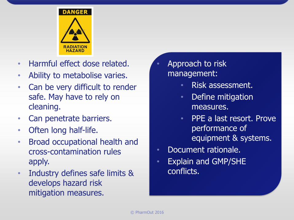
• Harmful effect dose related.
• Ability to metabolise varies.
• Can be very difficult to render safe. May have to rely on cleaning.
• Can penetrate barriers.
• Often long half-life.
• Broad occupational health and cross-contamination rules apply.
• Industry defines safe limits & develops hazard risk mitigation measures.
• Approach to risk management:
• Risk assessment.
• Define mitigation measures.
• PPE a last resort. Prove performance of equipment & systems.
• Document rationale.
• Explain and GMP/SHE conflicts.

© PharmOut 2016
Containment principles

© PharmOut 2016
Principles of handling hazardous materials – an escalating approach.
• Use an alternative less hazardous material.
• Dilute the hazardous agent.
• Work in a less hazardous material phase – liquid vs gas or solid/powder.
• Handle materials in closed systems.
• Place open systems in primary containment enclosures with secondary containment and PPE as appropriate.
• Place open process in containment room with reliance on PPE for operator protection.

© PharmOut 2016
Principles
Closed process
Open process in isolator
Open processOperator PPE

© PharmOut 2016
Open aseptic process in an isolator
• Which way would you go?
• -ve or +ve pressure isolator
• Leakage integrity of isolator
• Cleanliness Grade of the surrounding room
• Depends on the RISK of an adverse event:
• Operator exposure vs Sterility assurance.
Grade C/D Room +ve
Grade A Isolator+ve or -ve

© PharmOut 2016
Facility features
Layout, Air locks & Pressurisation

© PharmOut 2016
Airlocks in a containment scenario
Safe corridor 0
Process room++ve
A/L+ve
Sink A/L-ve
Process room- -ve
A/L-ve
Bubble A/L+ve
Process room- -ve
A/L-ve
Sink Bubble Cascade

© PharmOut 2016
Facility features
Room leakage
© PharmOut 2016
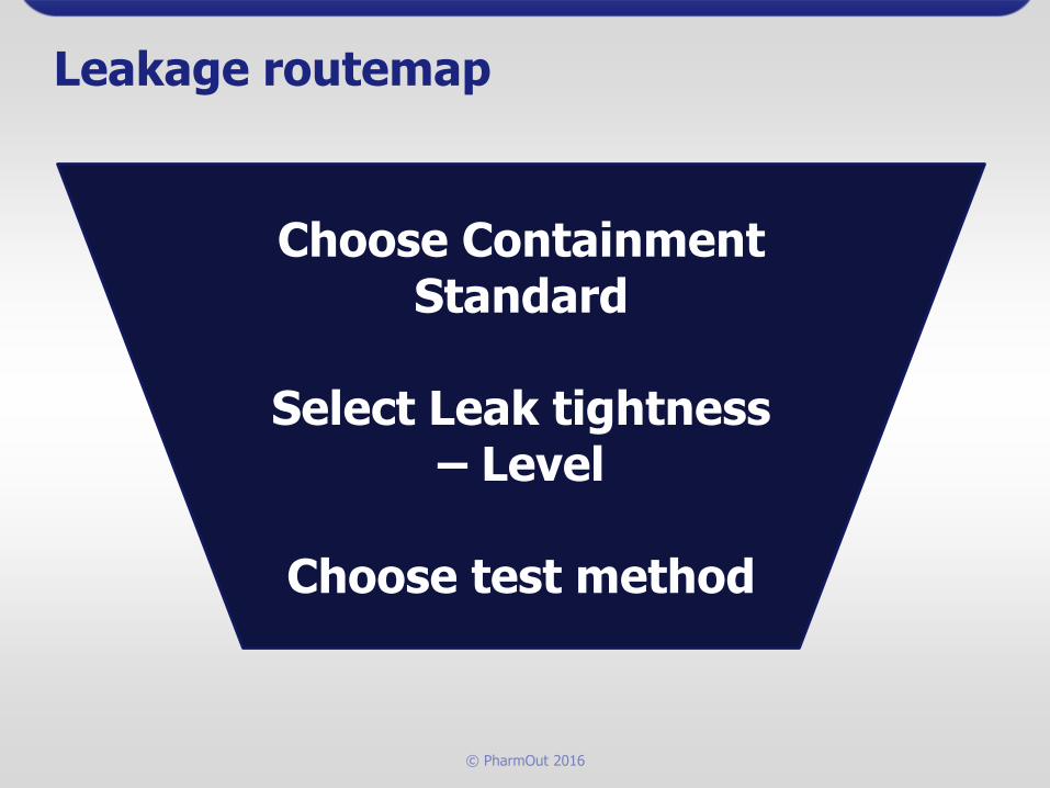
Leakage routemap
Choose Containment Standard
Select Leak tightness – Level
Choose test method

© PharmOut 2016
Available standards & guidance
Generally (exception Health Canada) national containment guidelines for
human & animal pathogens, and genetically manipulated organisms are silent
about room or device air-tightness (specific values).
• Means we have to use a risk based approach supported by the
available guidance and standards.
Most significant/important guidance & standards are:
• EN 12469:2000 – Microbiological safety cabinets.
• AS/NZS 2243.3-2002 Safety in laboratories - Microbiological aspects
and containment facilities.
• Canadian Guidance lbg_2004_e (Matrix 6 – Room Integrity).
• ASTM : E 779 – 03, Standard Test Method for Determining Air Leakage
Rate by Fan Pressurization

© PharmOut 2016
Most common test methods
• Pressure decay (low leakage small enclosures, gloves)
• Pressure hold or leakage rate (high leakage & large enclosures)
• Oxygen diffusion testing methods can be used (low leakage small enclosures,
gloves)
• Soap bubbles, aerosols, and ammonia can be used to trace leaks..
For test methods:
• EN/ISO14644-7 “Separative Enclosures”
• EN 12469 for microbiological safety cabinets.
• NSF 49 for microbiological safety cabinets.
• Lots of good information from the nuclear industry:
• e.g. ISO 10648-2 “Containment Enclosures- Classification according to leak tightness and
associated checking methods”.
Enclosure Leakage

© PharmOut 2016
Choosing a level of leakage(1)This needs to be a risk based decision. Take into account:
• The level/class of biological agent.
• The concentration of the biological agent inside the containment
boundary.
• The concentration of bio-inactivation chemical (usually
formaldehyde, chlorine dioxide or hydrogen peroxide) inside the
containment boundary.
• The potential for escape through the containment envelope
(usually HVAC failure modes will present the worst case
situation), and the relationship with the resilience of the
associated HVAC system.
• Also critical if a classified cleanroom is held at negative pressure.

© PharmOut 2016
Choosing a level of leakage (2)The clearest standard to use is AS/NZS 2243.3-2002
• Appendix G applies. This considers the following:
• The risk of biological agent escape (pathogen hazard)
• Acceptable loss of bio-decontamination gas commensurate with obtaining
the necessary kill
• The acceptable leakage of the bio-decontamination gas through the fabric
• It defines a leakage coefficient b (m3/Pa.sec)
• Gives examples of b for isolators, Australian CSIRO, US Dept of Agriculture,
and Health Canada
• Gives suggested leakage levels:
• CL3 & 4 using Class lll MBSCs, b= 10-4 10-5 at 200 Pa.
• CL 3 or 4 using room as primary containment , b= 10-6 at 200 Pa.

© PharmOut 2016
Choosing a level of leakage (3)
Look at the application of these leakage levels using AS/NZS 2243.3-
2002 :
• Consider a CL3 room using Class lll MBSCs
• b= 10-4 10-5 at 200 Pa from the standard
• This gives a leakage range of 20 2 litres/sec at 200 Pa for any
size room
• It is also necessary to test the safety & efficacy of the bio-
decontamination process for the completed facility
Other common leakage specifications – there are many used by different
organisations.
• ~0.1 m3/m2.hr – based on surface area of containment
© PharmOut 2016
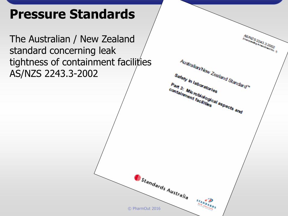
Pressure Standards
The Australian / New Zealand standard concerning leak tightness of containment facilitiesAS/NZS 2243.3-2002

© PharmOut 2016
Pressure Standards
ASTM Test Method standardASTM : E 779 – 03

© PharmOut 2016
Specification of fabric & finishes
Options for construction
• In-situ (stick built)
• Pre-fabricated & pre-finished systems (cleanroom)
• Evaluation of options
Specification of components & details
• Services penetrations
• Windows
• Doors
Build and approve mock-up unless prior experience exists

© PharmOut 2016
Specify the Containment solution
Materials, components

© PharmOut 2016
Services entry details
Services distributed
in “safe” service
chase. Entries
inspectable both
sides.
Walk-in service chase between clean containment labs

© PharmOut 2016
Services entry detailsDucts & pipes enter via service plates on ceiling membrane.
Entries inspectable both sides.

© PharmOut 2016
Services entry detailsIndustrial transits used to provide flexible entry of cables and pipes. Inspectableboth sides.Door control mechanism (access & interlock), surface mounted in sealed assembly to avoid wall penetrations.
Interlock status
Card reader
Small power
outlet

© PharmOut 2016
Construction & Installation
QA
(Including Leak Testing)

© PharmOut 2016
QA Construction & Installation
Clean construction protocol
• Control materials
• Inspect build quality progressively
Leak testing – select appropriate method
• Pressure hold – leak rate test. (most suitable for CL3 and CL4 cabinet line
rooms.
• Pressure decay (most suitable for Class lll MBSCs and CL4 rooms).
• Photometer & aerosol method (method suitable for seeking leak pathways).
• Ultrasound (method suitable for seeking leak pathways).
• Tracer gas (method suitable for seeking leak pathways).
Undertake leak testing progressively
• At the conclusion of the construction of the basic shell.
• When service penetrations have been cut and service entries installed.
• When final finishes have been applied.

© PharmOut 2016
Pressure Hold Test Apparatus
Testing in accordance with ASTM : E 779 – 03.
Very similar to a ductwork leak-rate test.Measures the air volume required to compensate for leakage and maintain constant pressure.Typical test pressure 50-200 Pa
P

© PharmOut 2016
Pressure Hold Test Apparatus
Test being applied to CL3 and 4 containment facilities.
Notice the blank door used for this test, with pressure tapping connected to the test apparatus.
This test was used to prove compliance with a leakage rate specified in accordance with AS/NZS 2243.3-2002 . The test was carried out in accordance with the principles specified in ASTM : E 779 – 03
Image courtesy of Bovis Lend Lease

© PharmOut 2016
And finallyOngoing Operations
Periodic Room Leak Testing

© PharmOut 2016
Routine room leakage test
Not mandated in regulations (typical for MBSCs).
Becoming more common – safety risk management.
Typical frequencies
• 6 monthly
• Annually
• For cause – e.g. After major maintenance or works.
Infrastructure should be build in to do this conveniently
• Ability to isolate the HVAC system and any bio-safety cabinet connections.
• Provision of a port to apply test pressure to each separate enclosure to be
tested.
• Availability of test points for pressure monitoring (and temperature in the case
of the pressure decay test).
© PharmOut 2016
Facility features
HVAC systems & Air filtration

© PharmOut 2016
Potent Compounds - OSD, API Use of HEPA filters• Cross-contamination control in recirculation air handling
systems.
• Prevention of discharge of potent compound dust to
atmosphere – security or policing filters.
• HEPA filters of H13 or H14 specification are chosen
because they can be leak tested:
• Aerosol photometer method – scan or average leak test.
• Particle counter method.

© PharmOut 2016
Let’s look at some of the position options
There are several possible locations:
• Recirculation systems –
• 1. Final filter in air supply AHU.
• 2. Terminal supply to room.
• 3. In Return air duct to AHU.
• 4. In Return at room boundary.
• Once through systems
• 5. In Exhaust air duct to atmosphere.
• 6. In Exhaust at room boundary + In Exhaust to
atmosphere
Incre
asin
g P
ote
ncy/T
ox
icity

© PharmOut 2016
1. Recirculation–HEPA at AHU Supply

© PharmOut 2016
2. Recirculation–HEPA at Room Supply Terminal

© PharmOut 2016
Process
Room 2Process
Room 1
F7 - + F7 Option H13
F7
H13 or 14
G4
3. Recirculation – In return duct to AHU
G4

© PharmOut 2016
Process
Room 2Process
Room 1
F7 - + F7 Option H13
G4 +H13/14
4. Recirculation – In return at room boundary
G4 +H13/14

© PharmOut 2016
5. Once Through – HEPA at room exhaust

© PharmOut 2016
6. Once Through –HEPA at room exhaust + System Exhaust
Bag-outFilter in duct

© PharmOut 2016
Extract - Double Exhaust room filter (with bag-in/bag-out)
H14
G4
TSD
H14
Camfil WM BIBO illustrated

© PharmOut 2016
Bag-out systems
• Only provides protection to personnel during filter change.
• Essential in chemical and potent compound handling safety.
• Should not be used in bio-safety applications.
• Is a cumbersome
manipulation to
execute well.
• Consumes additional
space in technical
areas.

© PharmOut 2016
In-situ testing options
& developments

© PharmOut 2016
In-situ leak test methods
Most common• Aerosol/Photometer method using Emery 3004 PAO.
• Most parties are happy with volumetric , global or average leak test; some require face scan leak test.
Some• Use particle counter with enhanced aerosol.
• Most happy with volumetric or average leak test; some require face scan leak test.
• A few using automated face scan particle counter method.
A few• Use biological challenge (bacillus Subtilis-Collison aerosol
generator & cascade impactor sampler)
© PharmOut 2016
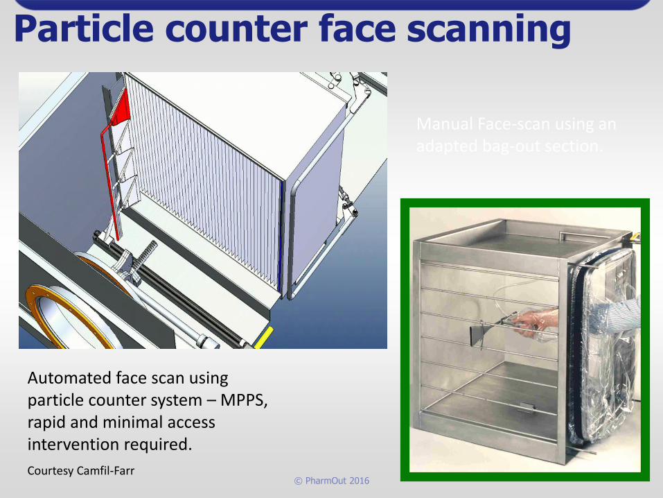
Particle counter face scanning
Automated face scan using particle counter system – MPPS, rapid and minimal access intervention required.
Courtesy Camfil-Farr
Manual Face-scan using an adapted bag-out section.

© PharmOut 2016
Risk of missing a leak – single hole equivalent – PAO & Photometer
Will different leak test accept
criteria detect the leaks ?
Global Leak Test
single hole 0.01% 0.003% 0.001%
1 mm dia no no no
2 mm dia no no no
3 mm dia no no yes
6 mm dia no yes yes
10 mm dia yes yes yes
80 mg/litre Emery 3004 challenge
610 x 610 filter handling 0.5 m3/sec
Assume all leakage through single hole (a simple approximation)
This is why a scan test is better than an average volumetric test.
This is why for higher hazard groups, 2 HEPAs in series are required.

© PharmOut 2016
A Filtration Route map
• Be aware of the filter grades and how they are tested by the
suppliers.
• Understand the configuration options.
• Define the stages of filtration required (Supply & Extract).
Including pre-filters to prolong HEPA life.
• Select the in-situ leak test required (Face scan vs Average
Volumetric).
• Configure filter network.
• Develop the leak testing procedure (on-line or off-line, depending
on redundancy in the design).
• Review change-out procedure.

© PharmOut 2016
Thanks for your attention Questions???

© PharmOut 2016
This presentation has been prepared
and delivered by:-
Gordon J Farquharson
Principal
Critical Systems Ltd
Consulting in Safety & Quality Critical Systems
Guildford, Surrey, GU1 2SY, UK
tel +44 (0)1252 703 663
www.critical-systems.co.uk
CRI ICAL
SYSTEMS
CRI ICAL
SYSTEMS