a vapor containment performance protocol for closed … · a vapor containment performance protocol...
TRANSCRIPT
This information is distributed solely for the purpose of pre dissemination peer review under applicable information quality guidelines. It has not been formally disseminated by the National Institute for Occupational Safety and Health. It does not represent and should not be construed to represent any agency determination or policy.
1
A Vapor Containment Performance Protocol for Closed System Transfer Devices Used During Pharmacy Compounding and Administration of Hazardous Drugs
This information is distributed solely for the purpose of pre dissemination peer review under applicable information quality guidelines. It has not been formally disseminated by the National Institute for Occupational Safety and Health. It does not represent and should not be construed to represent any agency determination or policy.
2
Disclaimer Mention of any company or product does not constitute endorsement by NIOSH. In addition, citations to websites external to NIOSH do not constitute NIOSH endorsement of the sponsoring organizations or their programs or products. Furthermore, NIOSH is not responsible for the content of these websites. All Web addresses referenced in this document were accessible as of the publication date.
Authorship This document is based on the research of National Institute for Occupational Safety and Health (NIOSH) scientists Deborah V.L. Hirst, Ph.D., P.E. and Kenneth R. Mead, Ph.D., P.E., the principal authors. Coauthors included Luci Power, MS, RPh, of Power Enterprises and Eric Kastango, MBA, RPh, FASHP, of Clinical IQ, LLC, as well as NIOSH personnel Ronald Kovein, EET; Dylan Neu; and Amy Feng, M.S. Consultation assistance was provided by James Wagner of Controlled Environment Consulting. The document was prepared by NIOSH staff. Cover design graphics were developed by NIOSH engineering technician Graeham Heil. Pictures are courtesy of NIOSH photographer Brenda Jones. Cover design and document layout was also performed by Brenda Jones of NIOSH.
Acknowledgments The contributions of the following individuals are greatly appreciated: Dawn R. Farwick, Stanley Shulman, Trudi McCleery, Jerry Kratzer, Daniel Farwick, Michael Gressel, Duane Hammond, Thomas Connor, Michael Elliot, Jack Pretty, Robert Streicher, Paula Fey O’Connor, Donald Booher, Barbara MacKenzie, and Kenneth Fent.
This information is distributed solely for the purpose of pre dissemination peer review under applicable information quality guidelines. It has not been formally disseminated by the National Institute for Occupational Safety and Health. It does not represent and should not be construed to represent any agency determination or policy.
3
ContentsDisclaimer ................................................................................................................................................................. 2
Authorship ................................................................................................................................................................. 2
Acknowledgments ..................................................................................................................................................... 2
Introduction ............................................................................................................................................................... 4
Background ........................................................................................................................................................... 9
CSTD Vapor Containment Test Development ........................................................................................................ 10
Environmental Test Chamber .............................................................................................................................. 12
NIOSH Application of the Vapor Containment Performance Protocol .............................................................. 13
Data Analysis................................................................................................................................................... 13
Data Interpretation and Discussion.................................................................................................................. 16
Application of the Vapor Containment Performance Protocol ............................................................................ 19
Summary ............................................................................................................................................................. 19
References ........................................................................................................................................................... 22
Figures ................................................................................................................................................................. 25
Appendix A—Laboratory Vapor Containment Performance Test Protocol for Closed System Transfer Devices (CSTDs) ................................................................................................................................................................... 30
Purpose ................................................................................................................................................................ 30
Scope of Use ........................................................................................................................................................ 30
Compounding and Administration Materials ...................................................................................................... 31
Vial Preparation ................................................................................................................................................... 32
Test Procedures ................................................................................................................................................... 32
Task 1: Prepare 500 mL 0.9% sodium chloride IV bag with 90 mL of 70% IPA vials using 45 mL transfers33
Task 2: Prepare 45 mL 70% IPA in 60 mL syringes for IV push and Y-site administration .......................... 36
Data Analysis....................................................................................................................................................... 40
Appendix B—Materials and Assembly of Environmental Test Chamber .............................................................. 44
Appendix C—IPA Detector Span Check ................................................................................................................ 53
Appendix D—Model Closed System Transfer Device Certification ...................................................................... 55
This information is distributed solely for the purpose of pre dissemination peer review under applicable information quality guidelines. It has not been formally disseminated by the National Institute for Occupational Safety and Health. It does not represent and should not be construed to represent any agency determination or policy.
4
Introduction
This protocol originates from a collaborative effort between healthcare industry representatives and
NIOSH researchers to develop a performance test protocol for closed system transfer devices (CSTDs)
[NIOSH 2004]. A CSTD, also known as a closed system drug-transfer device, is used to facilitate the
transfer of drug from one reservoir to another, and may be used throughout the drug-handling chain
from pharmaceutical compounding to patient dose administration. CSTDs limit the potential for
aerosolizing drug contamination and exposing workers to sharps, thus reducing the likelihood of
occupational exposure to hazardous drugs [NIOSH 2004]. By definition, the CSTD mechanically
prohibits the transfer of environmental contaminants into the system and the escape of hazardous drug or
vapor concentrations outside the system [NIOSH 2004]. CSTD manufacturers utilize one of two
approaches to achieve the “…prohibits the transfer…” requirements in this definition: (1) those that
intend to function as a truly closed system where a physical barrier prevents all mass from crossing the
system boundary or (2) those that intend to use air-cleaning technologies to specifically prohibit
environmental contaminants and hazardous drug concentrations from crossing the system.
In 2004, NIOSH released the NIOSH Alert: Preventing Occupational Exposures to Antineoplastic and
Other Hazardous Drugs in Health Care Settings [NIOSH 2004]. In this Alert, NIOSH identifies CSTDs
as supplemental controls that should only be used in combination with primary engineering controls
(biological safety cabinets and containment isolators) to further protect against worker exposures to
hazardous drugs. At the time of the release of the NIOSH Alert, limited models of CSTDs were
available in the market. More recently, the number of marketed CSTD models has increased. Interest in
This information is distributed solely for the purpose of pre dissemination peer review under applicable information quality guidelines. It has not been formally disseminated by the National Institute for Occupational Safety and Health. It does not represent and should not be construed to represent any agency determination or policy.
5
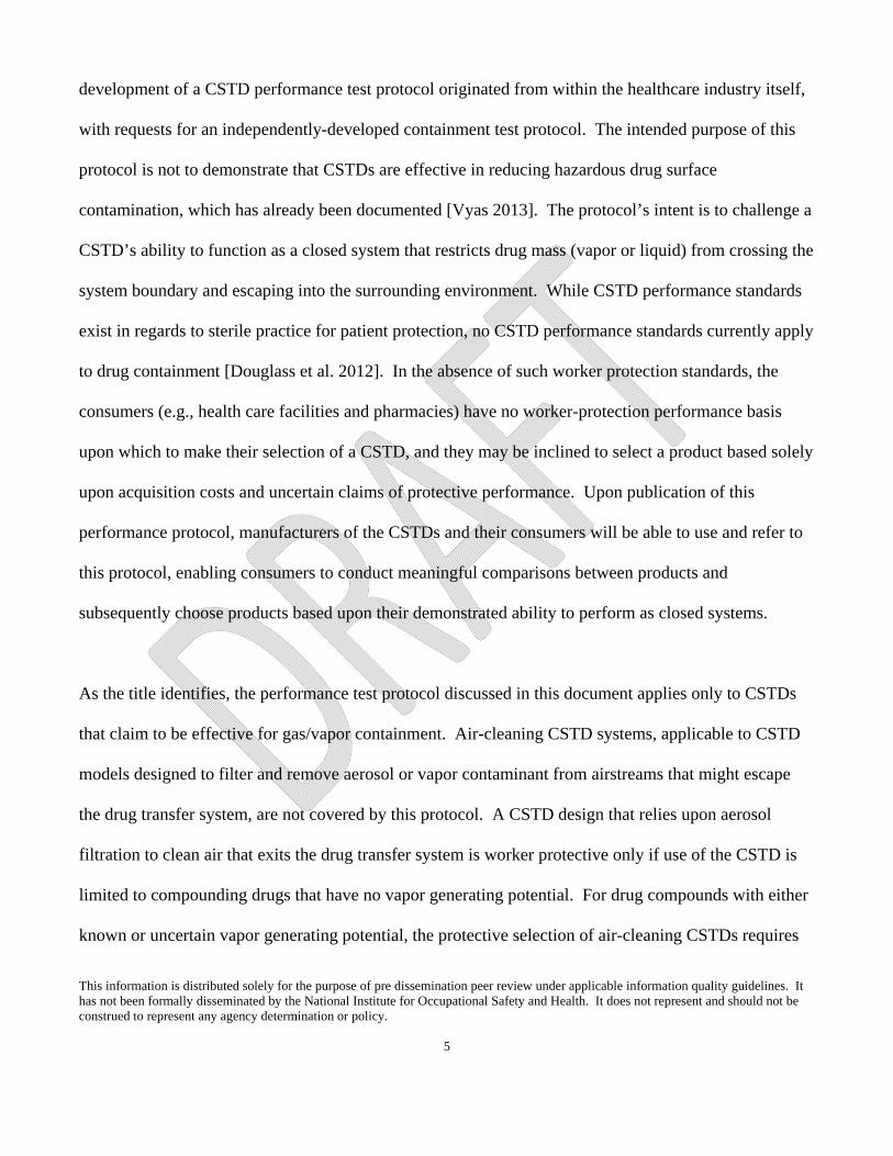
development of a CSTD performance test protocol originated from within the healthcare industry itself,
with requests for an independently-developed containment test protocol. The intended purpose of this
protocol is not to demonstrate that CSTDs are effective in reducing hazardous drug surface
contamination, which has already been documented [Vyas 2013]. The protocol’s intent is to challenge a
CSTD’s ability to function as a closed system that restricts drug mass (vapor or liquid) from crossing the
system boundary and escaping into the surrounding environment. While CSTD performance standards
exist in regards to sterile practice for patient protection, no CSTD performance standards currently apply
to drug containment [Douglass et al. 2012]. In the absence of such worker protection standards, the
consumers (e.g., health care facilities and pharmacies) have no worker-protection performance basis
upon which to make their selection of a CSTD, and they may be inclined to select a product based solely
upon acquisition costs and uncertain claims of protective performance. Upon publication of this
performance protocol, manufacturers of the CSTDs and their consumers will be able to use and refer to
this protocol, enabling consumers to conduct meaningful comparisons between products and
subsequently choose products based upon their demonstrated ability to perform as closed systems.
As the title identifies, the performance test protocol discussed in this document applies only to CSTDs
that claim to be effective for gas/vapor containment. Air-cleaning CSTD systems, applicable to CSTD
models designed to filter and remove aerosol or vapor contaminant from airstreams that might escape
the drug transfer system, are not covered by this protocol. A CSTD design that relies upon aerosol
filtration to clean air that exits the drug transfer system is worker protective only if use of the CSTD is
limited to compounding drugs that have no vapor generating potential. For drug compounds with either
known or uncertain vapor generating potential, the protective selection of air-cleaning CSTDs requires
This information is distributed solely for the purpose of pre dissemination peer review under applicable information quality guidelines. It has not been formally disseminated by the National Institute for Occupational Safety and Health. It does not represent and should not be construed to represent any agency determination or policy.
6
specific test data for every drug type and formulation they will contact, since air-cleaning technologies
can have varying efficiencies based upon the chemical and physical make-up of the contaminant.
The CSTD test protocol is located in Appendix A—Laboratory Vapor Containment Performance Test
Protocol for CSTDs. Initially, NIOSH researchers presented their draft test protocol for performance
and concept testing to the CSTD focus group, a subgroup of the NIOSH Hazardous Drug Working
Group. Pharmacist partners within the focus group identified specific compounding and drug-
administering tasks to incorporate into the protocol to ensure that the evaluated tasks represented real
world health care industry scenarios. The NIOSH researchers and pharmacist partners conducted
preliminary test runs using a NIOSH-designed environmental test chamber and data collection protocol.
While results of the preliminary test runs verified the protocol’s concept, additional modifications to the
environmental test chamber and performance test protocol were necessary. Subsequently, NIOSH
engineers met again with the CSTD focus group to evaluate CSTD vapor containment using an updated
performance test protocol and a new environmental test chamber design. Testing of the established
protocol used registered pharmacists familiar with CSTDs who performed each of the protocol-
prescribed compounding/administration tasks while using multiple manufacturers and types of CSTDs.
The use of challenge agents as hazardous contaminant substitutes is a valuable practice used to evaluate
the performance of engineering control and work practice interventions designed to mitigate
occupational exposures [Mead et al. 1999; Nygren et al. 2002; Steil 2011]. It is not necessary for the
challenge agent to mimic the chemical or physical structure of the contaminant for which the
intervention is intended to control. Rather, the challenge agent selection is based upon the challenge
This information is distributed solely for the purpose of pre dissemination peer review under applicable information quality guidelines. It has not been formally disseminated by the National Institute for Occupational Safety and Health. It does not represent and should not be construed to represent any agency determination or policy.
7
agent’s ability to be easily and accurately detected, and can be used to evaluate the intervention and
assess the ability of the device to control the contaminant. For example, sulfur hexafluoride (SF6), an
inorganic tracer gas, is commonly used to test engineering controls designed to control gases, vapors,
and very small aerosols that are influenced by prevailing wind currents [NIOSH 1997]. Lactose powder
may be used as a challenge agent for controls and equipment intended to handle active pharmaceutical
ingredients [Steil 2011]. Fluorescent compounds that are only visible under ultraviolet light, are
commonly used to evaluate the effectiveness of engineering control and work practice interventions
intended to prevent contact contamination [Jorgenson et al. 2008; Massoomi 2009; Lamerie et al. 2011;
Power 2013]. For the CSTD vapor containment performance protocol, the desired challenge agent
required the ability to be manipulated as a liquid, since the CSTDs under evaluation were all designed
for transfer of liquid hazardous drugs between vessels or between a vessel and the patient. In addition,
since the protocol is a vapor containment test protocol, the challenge agent required a significant vapor
pressure in order to produce sufficient vapor for a rigorous challenge to the vapor containment
performance of the CSTD device. When used for an intervention evaluation purpose, selected challenge
agents should be relatively safe, easy to acquire, and accurately measurable in low concentrations. For
the vapor containment performance protocol for closed system transfer devices, isopropyl alcohol (70%)
(IPA) was the chosen challenge agent. The selection of IPA as the challenge agent was based on several
factors:
IPA is a liquid when contained at room temperature and can be manipulated using the same
syringes, tubing, bags and vials that are used for compounding and administration of hazardous
drugs;
This information is distributed solely for the purpose of pre dissemination peer review under applicable information quality guidelines. It has not been formally disseminated by the National Institute for Occupational Safety and Health. It does not represent and should not be construed to represent any agency determination or policy.
8
Background concentrations of IPA can be easily removed from the test environment using
affordable and readily-available organic vapor filters, thus measured concentrations within the
test environment can be exclusively attributed to the IPA challenge agent under manipulation
within the CSTD;
IPA has a high vapor pressure that easily results in vapor generation at standard room
temperature and pressure, thus it intentionally provides a rigorous challenge for CSTDs that
claim to provide a “closed system” capable of containing both aerosol and vapor releases
generated during hazardous drug compounding;
IPA’s high vapor pressure also results in quick evaporation and easy detection of any liquid
challenge agent that escapes the closed system boundaries of the CSTD device whereas the
detection of leaked liquids that did not evaporate would be subject to the detection, sampling and
analytical errors associated with surface-wipe sampling methods;
IPA is easily detected using highly specific real-time detectors that are commonly available
within the pharmacy certification community; and
IPA is a relatively safe challenge agent selection that is commonly available within pharmacy
compounding environments.
During evaluations of the vapor containment performance protocol, a highly specific gas analyzer
(hereafter called IPA detector) was used to measure vapor concentrations of IPA that escaped the CSTD
during the identified tasks. The NIOSH researchers kept the IPA detector’s responses “blind” from the
CSTD focus group throughout the testing and data analysis process. In addition, a NIOSH statistician
blind-coded the instrument responses to prevent association of containment performance with any
This information is distributed solely for the purpose of pre dissemination peer review under applicable information quality guidelines. It has not been formally disseminated by the National Institute for Occupational Safety and Health. It does not represent and should not be construed to represent any agency determination or policy.
9
individual CSTD. NIOSH personnel subsequently evaluated the blind-coded data and statistics to
validate the test protocol procedures.
Background
Health care settings use CSTDs to transfer liquid drugs throughout their handling sequence from their
primary packaging to dose preparation and even patient administration. NIOSH recommends using
CSTDs when transferring hazardous drugs from primary packaging such as vials to dosing equipment
such as infusion bags, bottles, or pumps [NIOSH 2004]. CSTDs can protect the compounder during the
preparation of the hazardous drug as well as the attending health care worker(s) during later
administration of the hazardous drug to the patient [ISOPP 2007; Lamerie et al. 2011]. Although,
CSTDs may reduce worker exposure to hazardous drugs, they may not entirely eliminate exposure
[Sessink and Bos 1999; Nygren et al. 2002; NIOSH 2004; Harrison et al. 2006; Nyman et al. 2007;
Yoshida et al. 2009; Sessink et al. 2010; Vyas 2013]. It is also important that any selected CSTD be
compatible with the drugs and diluents to which it will come into contact. The use of CSTDs may not
be advised if the hazardous drugs are mixed with solvents, such as N,N-Dimethylacetamide, that are
incompatible with the plastic parts of CSTDs [ICU Medical 2015; ISMP 2015]. Such solvents might
dissolve the plastic components within the CSTD and allow the hazardous drug to escape or introduce
contaminants into the drug that jeopardize the health of the patient. NIOSH identifies CSTDs as
supplemental controls and advises that they are not a substitute for ventilated engineering controls such
as biological safety cabinets and containment isolators. During hazardous drug compounding, CSTDs
should only be used within ventilated engineering controls [NIOSH 2004; USP 2008]. Appropriate
This information is distributed solely for the purpose of pre dissemination peer review under applicable information quality guidelines. It has not been formally disseminated by the National Institute for Occupational Safety and Health. It does not represent and should not be construed to represent any agency determination or policy.
10
work practices and personal protective equipment should also be used when handling or operating
CSTDs [USP 2008].
Each CSTD system traditionally consists of a syringe adapter (a.k.a. CSTD syringe connector) plus three
component adapters: vial adapter, IV port adapter or Y-site adapter, and a bag adapter or infusion
adapter. Each of these adapters mates with the syringe adapter. The syringe adapter attaches to the
syringe in a manner that eliminates the presence of an exposed needle and thus prevents needle-stick
injuries. When used with a mating component adapter, the syringe-component adapter connection
allows for a sealed transfer of drug between the syringe and the attached component (vial, IV bag, or IV-
set). The vial adapter attaches to the vial and prevents leaks due to vacuum and overpressure when
diluent or air is injected or withdrawn [Connor et al. 2002; Wick et al. 2003]. The IV port adapter
provides a sealed connection between the IV administration set and the syringe adapter and is used to
transfer drug from the syringe into an IV administration set that is connected to the patient [Wick et al.
2003]. The bag adapter attaches to the IV bag and provides a sealed transfer route for the drug into the
IV bag [Wick et al. 2003].
CSTD Vapor Containment Test Development
The development of the CSTD vapor containment performance protocol required identification of a
functional test environment, a challenge agent for manipulation by the CSTD, a detection device for
measuring leaked challenge agent, and a list of prescribed tasks. NIOSH researchers developed a
strategy to quantitatively evaluate CSTD containment performance with a challenge agent (70% IPA),
within a custom-built environmental test chamber. The IPA detector used to measure IPA vapor that
This information is distributed solely for the purpose of pre dissemination peer review under applicable information quality guidelines. It has not been formally disseminated by the National Institute for Occupational Safety and Health. It does not represent and should not be construed to represent any agency determination or policy.
11
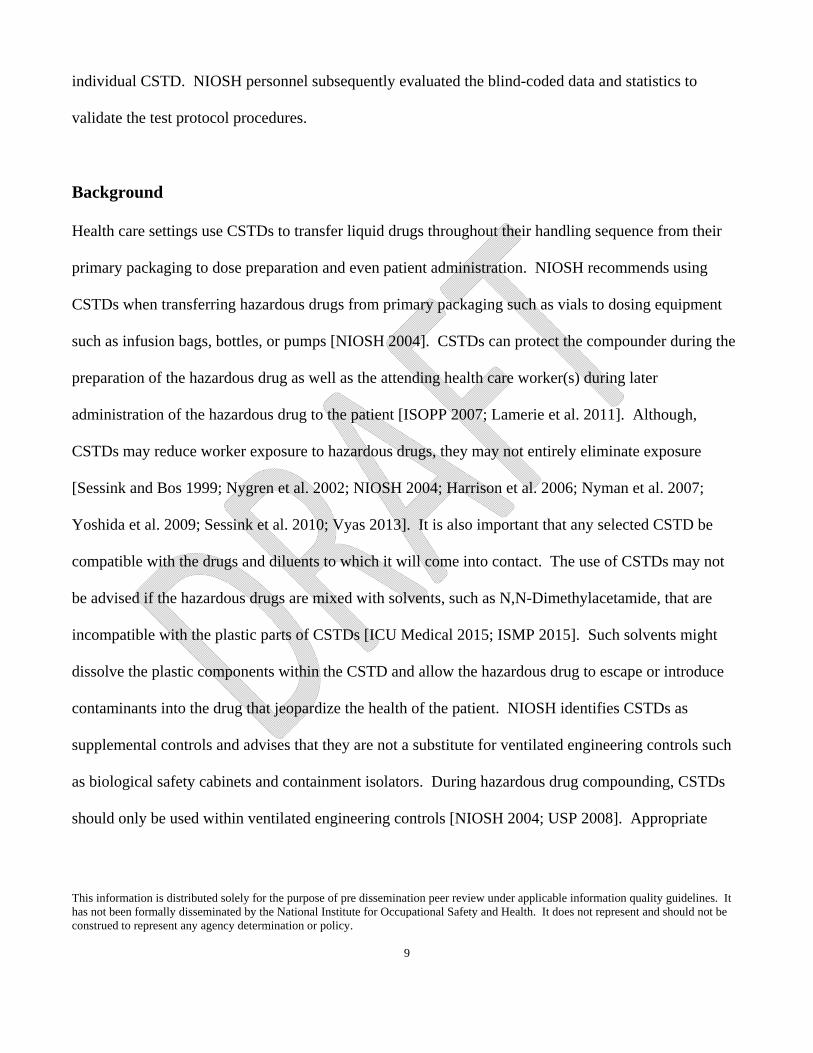
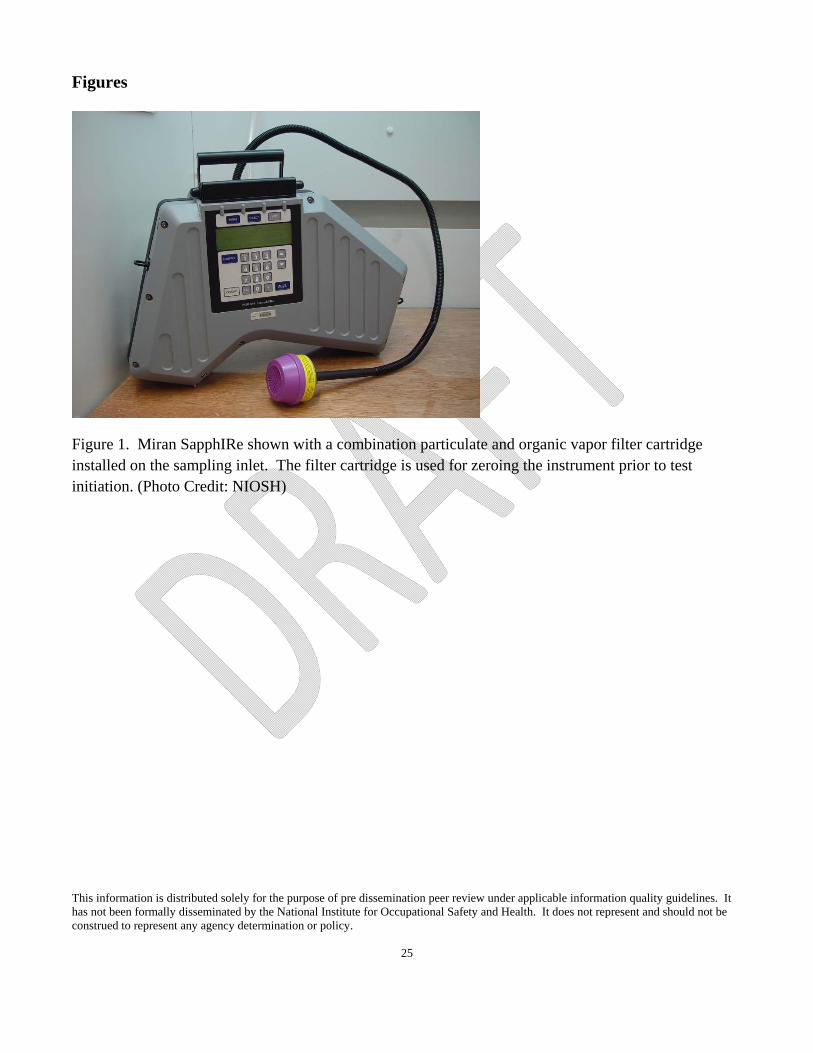
escaped during the prescribed pharmacy compounding and administration manipulations was a Miran
SapphIRe XL Infrared Analyzer model 205B-XL (Thermo Electron Corporation, Franklin, MA),
hereafter called Miran SapphIRe (Figure 1). The Miran SapphIRe was chosen to quantitatively measure
IPA because the instrument is capable of providing a specific response to IPA, the detection limit is
moderately low (0.30 ppm when calibrated and operated using the long pathlength with an 8.852
wavelength in IPA detection mode), and the instrument is regularly used among pharmacy
cleanroom/equipment certifiers and thus is commonly available to the industry. The Miran SapphIRe
measured IPA vapor concentrations from the test environment once every second and recorded the data
in parts per million, ppm.
The test protocol evaluated the CSTD systems during compounding and administration processes, which
included two tasks:
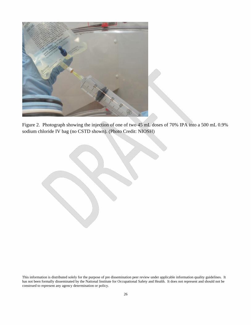
Task 1 (compounding)—the pharmacist prepared one 500 mL 0.9% sodium chloride IV bag with
90 mL of 70% IPA (Figure 2), using two 45 mL transfers from two 60 mL syringes and two vials
(Figure 3). The CSTD components evaluated under this task included one bag adapter, two vial
adapters, and two syringe adapters.
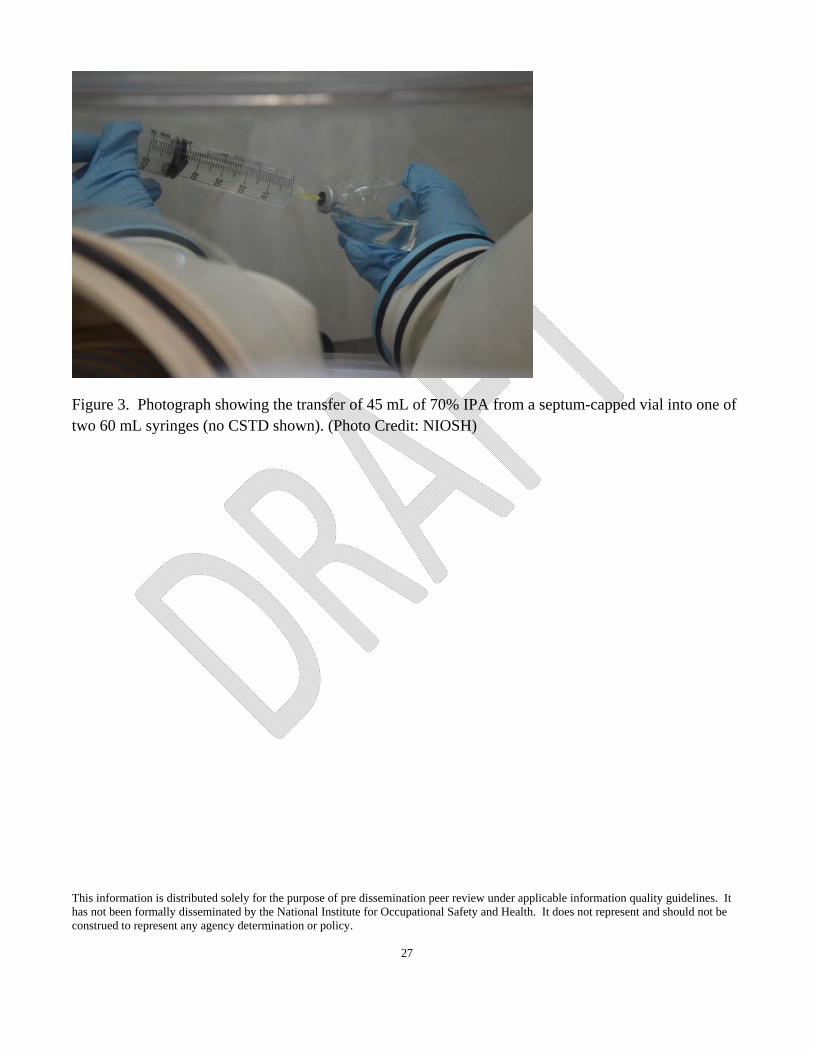
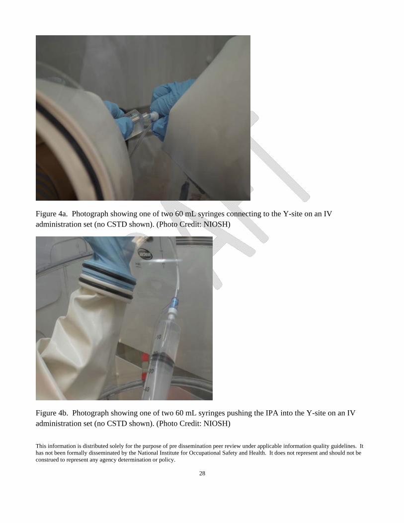
Task 2 (compounding/administration)—the pharmacist prepared a 45 mL dose of 70% IPA in
each of two 60 mL syringes for the IV push and injected each prepared syringe into the Y-site of
the IV tubing (Figures 3, 4a, and 4b). The CSTD components evaluated under this task included
two vial adapters, two syringe adapters, one bag adapter, and one IV port adapter.
This information is distributed solely for the purpose of pre dissemination peer review under applicable information quality guidelines. It has not been formally disseminated by the National Institute for Occupational Safety and Health. It does not represent and should not be construed to represent any agency determination or policy.
12
Environmental Test Chamber
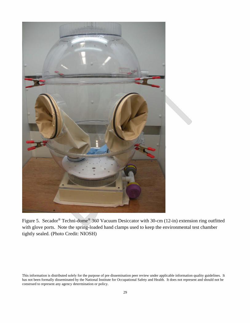
The environmental chamber selected for the CSTD vapor containment performance protocol was a
customized Secador® Techni-dome® 360 Large Vacuum Desiccator (Bel-Art Products, Pequannock, NJ)
(Figure 5). The Secador® Techni-dome® is a sphere of 52.1-centimeter (cm) inner diameter (20.5 inch
[in]) that separates at its horizontal equator into equal lower and upper halves. The NIOSH researchers
customized the sphere with a 30 cm (12 in) extension ring, fitted with 20 cm (8 in) glove ports and
installed between the lower and upper sphere halves (Custom Part #800260055, Bel-Art Products,
Pequannock, NJ). The addition of the extension ring converted the round Techni-dome® sphere into a
cylinder with hemispherical ends. This modified enclosure has sufficient interior volume to allow for
full pharmacy manipulations. The interior volume and wall-contour of the resulting test chamber
provides an optimum environment for introduction of clean make-up air into the bottom of the chamber
while sampling for escaped IPA vapor through a sample port in the chamber’s top. The IPA detector’s
sampling pump pulls make-up air into the bottom of the test chamber where it distributes across the full
cross-section and flows upward towards the chamber’s sampling port. Room air first passes through two
organic vapor respirator cartridges to provide a source of clean make-up air into the environmental test
chamber. The respirator cartridges connect to the bottom of the environmental test chamber using
polyvinyl chloride (PVC) pipe and fittings. Near the bottom of the chamber, a coarse nonwoven filter
and a perforated shelf provide sufficient backpressure to distribute the clean make-up air evenly across
the environmental test chamber’s horizontal cross-section. If IPA vapor escapes the CSTD system
during a pharmacy manipulation, it mixes with the upwardly moving make-up air, exits the chamber at
the sampling port connection, and the IPA detector detects the resulting concentration regardless of the
CSTD system proximity in the environmental test chamber. The IPA detector samples the air from the
This information is distributed solely for the purpose of pre dissemination peer review under applicable information quality guidelines. It has not been formally disseminated by the National Institute for Occupational Safety and Health. It does not represent and should not be construed to represent any agency determination or policy.
13
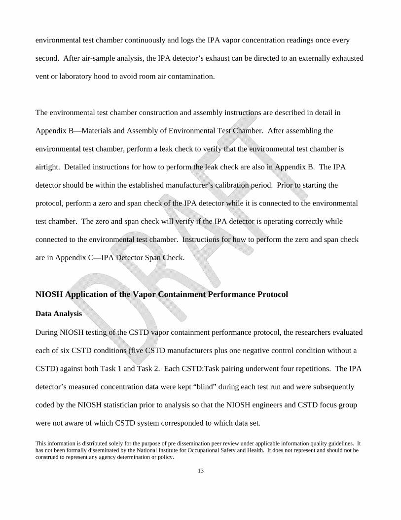
environmental test chamber continuously and logs the IPA vapor concentration readings once every
second. After air-sample analysis, the IPA detector’s exhaust can be directed to an externally exhausted
vent or laboratory hood to avoid room air contamination.
The environmental test chamber construction and assembly instructions are described in detail in
Appendix B—Materials and Assembly of Environmental Test Chamber. After assembling the
environmental test chamber, perform a leak check to verify that the environmental test chamber is
airtight. Detailed instructions for how to perform the leak check are also in Appendix B. The IPA
detector should be within the established manufacturer’s calibration period. Prior to starting the
protocol, perform a zero and span check of the IPA detector while it is connected to the environmental
test chamber. The zero and span check will verify if the IPA detector is operating correctly while
connected to the environmental test chamber. Instructions for how to perform the zero and span check
are in Appendix C—IPA Detector Span Check.
NIOSH Application of the Vapor Containment Performance Protocol
Data Analysis During NIOSH testing of the CSTD vapor containment performance protocol, the researchers evaluated
each of six CSTD conditions (five CSTD manufacturers plus one negative control condition without a
CSTD) against both Task 1 and Task 2. Each CSTD:Task pairing underwent four repetitions. The IPA
detector’s measured concentration data were kept “blind” during each test run and were subsequently
coded by the NIOSH statistician prior to analysis so that the NIOSH engineers and CSTD focus group
were not aware of which CSTD system corresponded to which data set.
This information is distributed solely for the purpose of pre dissemination peer review under applicable information quality guidelines. It has not been formally disseminated by the National Institute for Occupational Safety and Health. It does not represent and should not be construed to represent any agency determination or policy.
14
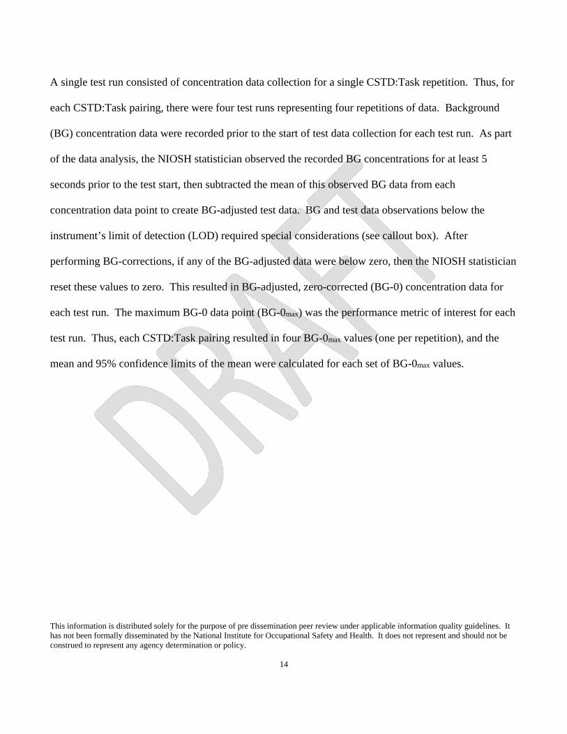
A single test run consisted of concentration data collection for a single CSTD:Task repetition. Thus, for
each CSTD:Task pairing, there were four test runs representing four repetitions of data. Background
(BG) concentration data were recorded prior to the start of test data collection for each test run. As part
of the data analysis, the NIOSH statistician observed the recorded BG concentrations for at least 5
seconds prior to the test start, then subtracted the mean of this observed BG data from each
concentration data point to create BG-adjusted test data. BG and test data observations below the
instrument’s limit of detection (LOD) required special considerations (see callout box). After
performing BG-corrections, if any of the BG-adjusted data were below zero, then the NIOSH statistician
reset these values to zero. This resulted in BG-adjusted, zero-corrected (BG-0) concentration data for
each test run. The maximum BG-0 data point (BG-0max) was the performance metric of interest for each
test run. Thus, each CSTD:Task pairing resulted in four BG-0max values (one per repetition), and the
mean and 95% confidence limits of the mean were calculated for each set of BG-0max values.
This information is distributed solely for the purpose of pre dissemination peer review under applicable information quality guidelines. It has not been formally disseminated by the National Institute for Occupational Safety and Health. It does not represent and should not be construed to represent any agency determination or policy.
15
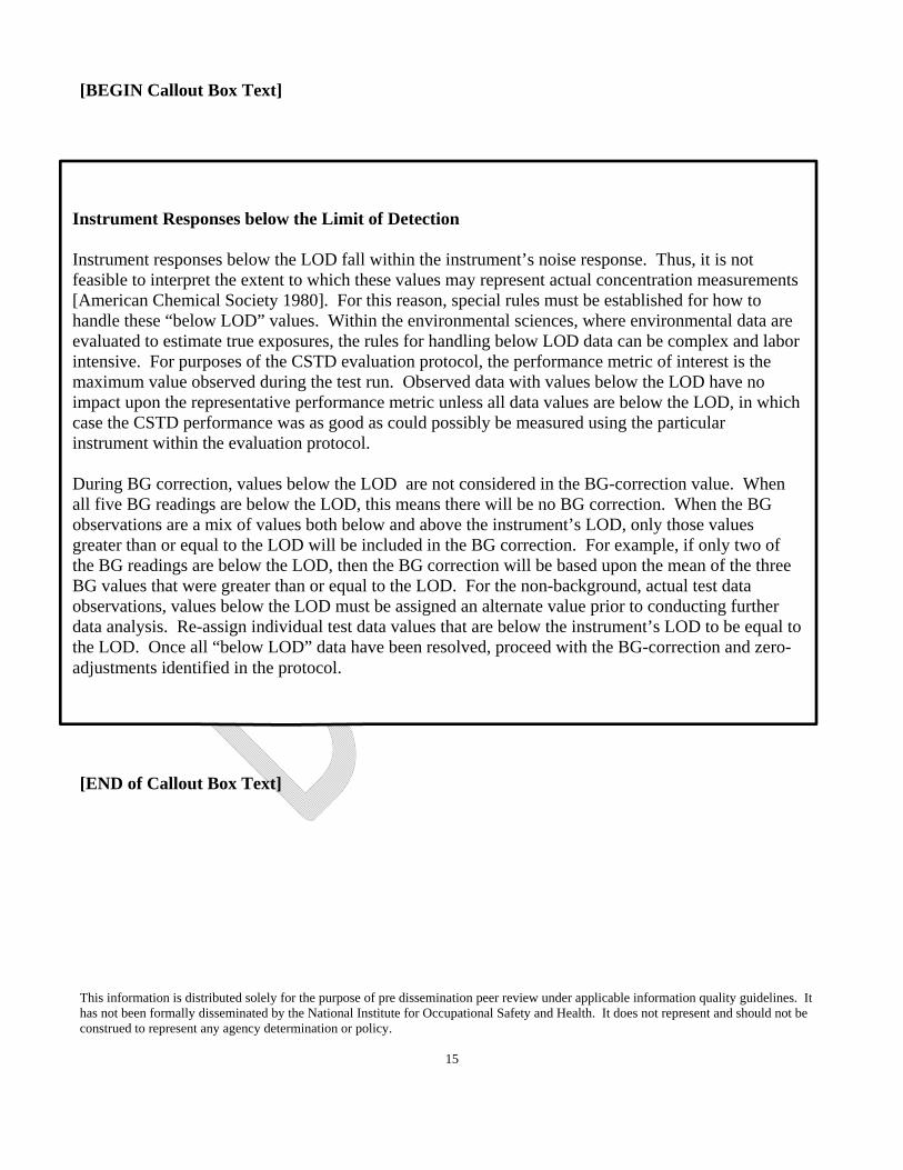
[BEGIN Callout Box Text]
[END of Callout Box Text]
Instrument Responses below the Limit of Detection Instrument responses below the LOD fall within the instrument’s noise response. Thus, it is not feasible to interpret the extent to which these values may represent actual concentration measurements [American Chemical Society 1980]. For this reason, special rules must be established for how to handle these “below LOD” values. Within the environmental sciences, where environmental data are evaluated to estimate true exposures, the rules for handling below LOD data can be complex and labor intensive. For purposes of the CSTD evaluation protocol, the performance metric of interest is the maximum value observed during the test run. Observed data with values below the LOD have no impact upon the representative performance metric unless all data values are below the LOD, in which case the CSTD performance was as good as could possibly be measured using the particular instrument within the evaluation protocol. During BG correction, values below the LOD are not considered in the BG-correction value. When all five BG readings are below the LOD, this means there will be no BG correction. When the BG observations are a mix of values both below and above the instrument’s LOD, only those values greater than or equal to the LOD will be included in the BG correction. For example, if only two of the BG readings are below the LOD, then the BG correction will be based upon the mean of the three BG values that were greater than or equal to the LOD. For the non-background, actual test data observations, values below the LOD must be assigned an alternate value prior to conducting further data analysis. Re-assign individual test data values that are below the instrument’s LOD to be equal to the LOD. Once all “below LOD” data have been resolved, proceed with the BG-correction and zero-adjustments identified in the protocol.
This information is distributed solely for the purpose of pre dissemination peer review under applicable information quality guidelines. It has not been formally disseminated by the National Institute for Occupational Safety and Health. It does not represent and should not be construed to represent any agency determination or policy.
16
Data Interpretation and Discussion
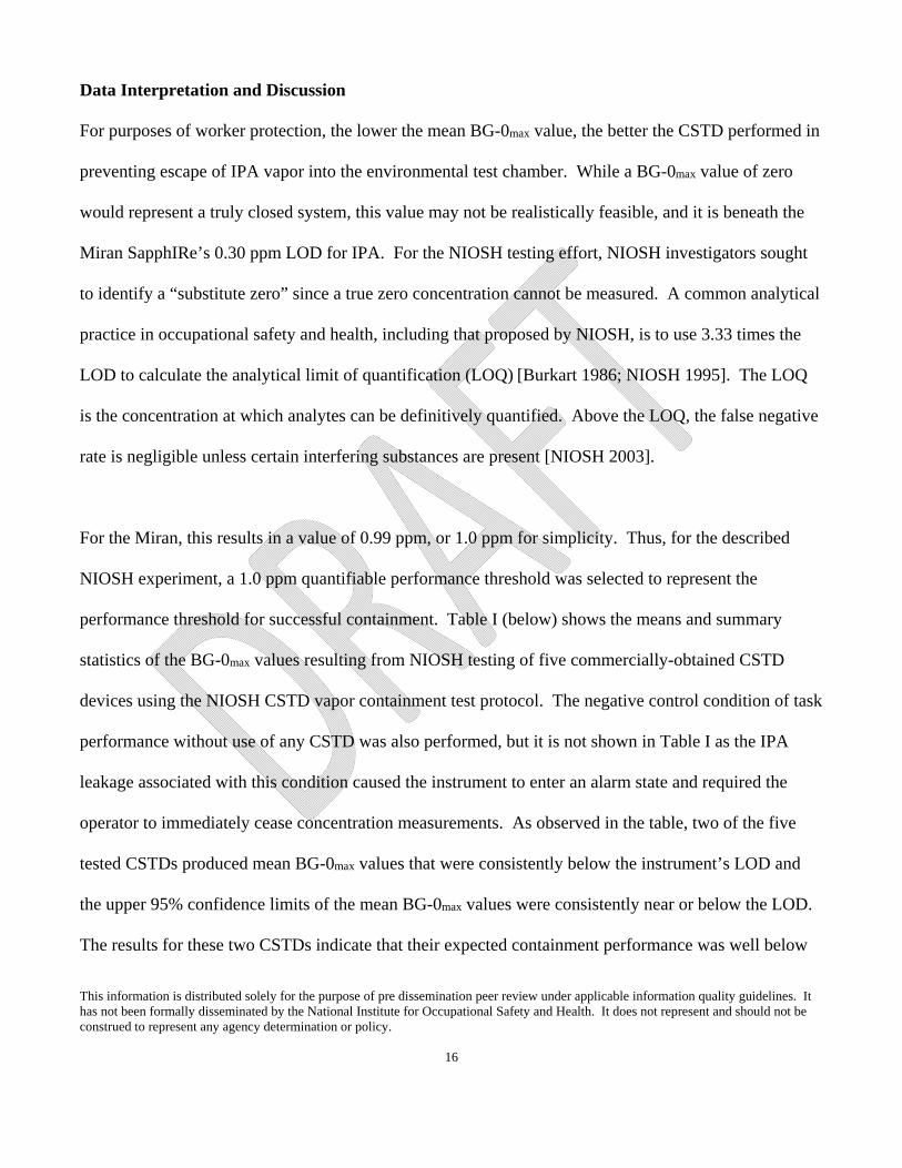
For purposes of worker protection, the lower the mean BG-0max value, the better the CSTD performed in
preventing escape of IPA vapor into the environmental test chamber. While a BG-0max value of zero
would represent a truly closed system, this value may not be realistically feasible, and it is beneath the
Miran SapphIRe’s 0.30 ppm LOD for IPA. For the NIOSH testing effort, NIOSH investigators sought
to identify a “substitute zero” since a true zero concentration cannot be measured. A common analytical
practice in occupational safety and health, including that proposed by NIOSH, is to use 3.33 times the
LOD to calculate the analytical limit of quantification (LOQ) [Burkart 1986; NIOSH 1995]. The LOQ
is the concentration at which analytes can be definitively quantified. Above the LOQ, the false negative
rate is negligible unless certain interfering substances are present [NIOSH 2003].
For the Miran, this results in a value of 0.99 ppm, or 1.0 ppm for simplicity. Thus, for the described
NIOSH experiment, a 1.0 ppm quantifiable performance threshold was selected to represent the
performance threshold for successful containment. Table I (below) shows the means and summary
statistics of the BG-0max values resulting from NIOSH testing of five commercially-obtained CSTD
devices using the NIOSH CSTD vapor containment test protocol. The negative control condition of task
performance without use of any CSTD was also performed, but it is not shown in Table I as the IPA
leakage associated with this condition caused the instrument to enter an alarm state and required the
operator to immediately cease concentration measurements. As observed in the table, two of the five
tested CSTDs produced mean BG-0max values that were consistently below the instrument’s LOD and
the upper 95% confidence limits of the mean BG-0max values were consistently near or below the LOD.
The results for these two CSTDs indicate that their expected containment performance was well below

This information is distributed solely for the purpose of pre dissemination peer review under applicable information quality guidelines. It has not been formally disseminated by the National Institute for Occupational Safety and Health. It does not represent and should not be construed to represent any agency determination or policy.
17
the 1.0 ppm performance threshold selected for the described NIOSH testing. These data show that
adoption of this LOQ threshold would be a realistically feasible threshold when using the prescribed test
protocol in the manner described by the NIOSH testing.

This information is distributed solely for the purpose of pre dissemination peer review under applicable information quality guidelines. It has not been formally disseminated by the National Institute for Occupational Safety and Health. It does not represent and should not be construed to represent any agency determination or policy.
18
Table I. Means and Summary Statistics of the BG-0max Values for Each CSTD:Task Pairing
Analysis Variable: BG-0max
Task
CSTD
Device
Number of
BG-0max Observations
Mean of
BG-0max
Observations (ppm)
Lower 95% Confidence Limit
(ppm)
Upper 95% Confidence Limit
(ppm)
Standard Deviation
(ppm)
1 1 4 0.25* 0.09 0.41 0.10
2 3 0.33* 0.19 0.48 0.06
3 4 8.8 5.4 12 2.1
4 4 8.9 -1.8 20 6.7
5 4 16 4.9 27 7.0
2 1 8 0.28* 0.18 0.37 0.12
2 6 0.25* 0.12 0.38 0.12
3 8 4.7 0.42 9.0 5.1
4 8 1.3 0.69 1.9 0.73
5 7 16 -3.5 35 21
Note: Values shown with an “*” had actual real-time concentration measurements below the
instrument’s reported LOD of 0.30 ppm. The previously described special rules for handling
data below the instrument’s LOD were applied to these values.
This information is distributed solely for the purpose of pre dissemination peer review under applicable information quality guidelines. It has not been formally disseminated by the National Institute for Occupational Safety and Health. It does not represent and should not be construed to represent any agency determination or policy.
19
Application of the Vapor Containment Performance Protocol
Interested parties may adopt the NIOSH Vapor Containment Performance Protocol for CSTDs as
described in this document for multiple purposes, including prototype evaluation by manufacturers,
comparative product evaluation by potential consumers or even adoption by jurisdictions for use as a
performance certification protocol. Depending upon the intended purpose, the declaration of a
performance threshold may not be beneficial. Where a performance threshold is desired, it is important
that the threshold actually be a value that is measurable by the analytical device in use. Values below
the instrument’s LOD will not meet this requirement. A calculated LOQ, as used during the NIOSH
CSTD testing, may be selected as the performance threshold. Alternatively, some other criterion such as
the detection instrument’s LOD may also be selected. If the vapor containment performance protocol is
adopted as a performance certification protocol, NIOSH recommends that an independent laboratory
perform the certification testing and generate a performance report that certifies the CSTD’s vapor
containment performance (see Appendix D—Model Closed System Transfer Device Certification
Letter).
Summary
Healthcare industry representatives and NIOSH researchers collaborated to develop the CSTD vapor
containment performance protocol. The purpose of the protocol was to test a CSTD’s capability to
perform as a closed system. As a test of the protocol, registered pharmacists, familiar with the use of
CSTDs, tested the protocol’s prescribed compounding and administration tasks using five commercially
available CSTDs. They also performed the assigned tasks using a negative control condition without a
This information is distributed solely for the purpose of pre dissemination peer review under applicable information quality guidelines. It has not been formally disseminated by the National Institute for Occupational Safety and Health. It does not represent and should not be construed to represent any agency determination or policy.
20
CSTD. Prescribed tasks were performed in an environmental test chamber with 70% IPA as the
challenge agent. A highly specific gas analyzer (Miran SapphIRe XL), with measurement capabilities
specific to IPA and with a low limit of detection, was used to detect vapor concentrations of escaped
IPA during the tasks. The instrument responses were background-corrected and kept blind from the
research team to protect against potential interpretation bias. While an instrument response of zero
would represent a true closed system, this measurement is not analytically feasible with real-time
detection as it is lower than any known instrument’s LOD for IPA. Thus, if a performance threshold is
desired, some alternative value (other than zero) must be chosen. The protocol has multiple applications
and can be used by manufacturers to evaluate prototype CSTDs, by consumers to compare CSTD
products, or by jurisdictions wishing to adopt the protocol for a performance certification protocol. If a
performance pass/fail threshold is desired, users of the protocol may choose to adopt a common
analytical practice in occupational safety and health (3.33 x instrument LOD) to determine a calculated
LOQ value as the pass/fail performance threshold [Burkart 1986; NIOSH 1995]. During NIOSH-
application of the proposed vapor containment performance protocol, two of the five tested CSTDs
consistently produced responses below the chosen analytical instrument’s calculated LOQ threshold.
The application of this vapor containment performance protocol can be useful to evaluate containment
efficacy of CSTDs without creating potential exposures to hazardous drugs. The protocol evaluates the
closed system performance of the CSTD. It can be used to provide baseline containment comparisons
between different makes and models of CSTDs and to evaluate containment performance evaluations for
the majority of hazardous drugs for which an analytical method does not yet exist. However, it is
important to note that the numerical results are not directly comparable to materials with different

This information is distributed solely for the purpose of pre dissemination peer review under applicable information quality guidelines. It has not been formally disseminated by the National Institute for Occupational Safety and Health. It does not represent and should not be construed to represent any agency determination or policy.
21
physical properties nor do the results guarantee any resulting exposures with actual hazardous drug
compounds will be safe or in compliance with any known occupational exposure limits.
This information is distributed solely for the purpose of pre dissemination peer review under applicable information quality guidelines. It has not been formally disseminated by the National Institute for Occupational Safety and Health. It does not represent and should not be construed to represent any agency determination or policy.
22
References
American Chemical Society [1980]. Guidelines for data acquisition and data quality evaluation in environmental chemistry. Anal Chem 52: 2242-2249. Burkart JA [1986]. General procedures for limit of detection calculations in the industrial hygiene chemistry laboratory. Appl Ind Hyg 1(3): 153-155. Butler O, Forder J, Saunders J [2014]. Analytical protocol for the sensitive determination of mannitol, sorbitol and glucose containing powders in pharmaceutical workplaces by ion chromatography using a pulsed amperometric detector. J Pharm Biomed Anal. 2014 Oct 12. pii: S0731-7085(14)00497-X. doi: 10.1016/j.jpba.2014.10.006. [Epub ahead of print]. Connor TH, Anderson RW, Sessink PJ, Spivey SM [2002]. Effectiveness of a closed-system device in containing surface contamination with cyclophosphamide and ifosfamide in an i.v. admixture area. Am J Health-Syst Pharm 59:68–72. Douglass K, Kastango E, Cantor P [2012]. State regulations impact USP <797> compliance. Pharmacy Purchasing & Products 9(4)(suppl). Harrison BR, Peters BG, Bing MR [2006]. Comparison of surface contamination with cyclophosphamide and fluorouracil using a closed-system drug transfer device versus standard preparation techniques. Am J Health-Syst Pharm 63: 1736-1744. ISOPP (International Society of Oncology Pharmacy Practitioners Standards Committee) [2007]. ISOPP standards of practice. Safe handling of cytotoxics. J Oncol Pharm Practice 13 (suppl):1-81. Jorgenson JA, Spivey SM, Au C, Cannan D, Ritter H, Smith B [2008]. Contamination comparison of transfer devices intended for handling hazardous drugs. Hos Pharm 43(9): 723-727. Lamerie TQ, Carrez L, Décaudin B, Bouchoud L, Goossens J, Barthélémy C, Bonnabry P, Odou P [2011]. Multiple-test assessment of devices to protect healthcare workers when administering cytotoxic drugs to patients. J Oncol Pharm Practice 18(2):191–200. Massoomi F [2009]. Assessing vial transfer devices for handling hazardous drugs. Pharmacy Purchasing & Products 6(3): 18-22. Mead KR, Mickelsen RL, Brumagin TE [1999]. Factory Performance Evaluations of Engineering Controls for Asphalt Paving Equipment. Appl Occup Environ Hyg 14(8): 565-573. NIOSH [1995]. Guidelines for air sampling and analytical method development and evaluation. Cincinnati, OH: U.S. Department of Health and Human Services, Centers for Disease Control and Prevention, National Institute for Occupational Safety and Health, DHHS (NIOSH) Publication No. 95-117.
This information is distributed solely for the purpose of pre dissemination peer review under applicable information quality guidelines. It has not been formally disseminated by the National Institute for Occupational Safety and Health. It does not represent and should not be construed to represent any agency determination or policy.
23
NIOSH [1997]. Engineering control guidelines for hot mix asphalt pavers: part 1—new highway-class pavers. By Mead K and Mickelsen L. Cincinnati, OH: U.S. Department of Health and Human Services, Centers for Disease Control and Prevention, National Institute for Occupational Safety and Health, DHHS (NIOSH) Publication No. 97-105. NIOSH [2003]. NIOSH Manual of Analytical Methods, Publication 2003-154. Retrieved August 29, 2014, from http://www.cdc.gov/niosh/docs/2003-154/ NIOSH [2004]. NIOSH alert: preventing occupational exposures to antineoplastic and other hazardous drugs in health care settings. Cincinnati, OH: U.S. Department of Health and Human Services, Centers for Disease Control and Prevention, National Institute for Occupational Safety and Health, DHHS (NIOSH) Publication No. 2004-165. Nygren O, Gustavsson B, Ström L, Eriksson R, Jarneborn L, Friberg A [2002]. Exposure to anti-cancer drugs during preparation and administration. Investigations of an open and a closed system. J Environ Monit 4: 739–742. Nyman HA, Jorgenson JA, Slawson MH [2007]. Workplace contamination with antineoplastic agents in a new cancer hospital using a closed-system drug transfer device. Hos Pharm 2(3): 219-225. Power LA [2013]. Closed-system transfer devices for safe handling of injectable hazardous drugs. Pharm Practice News June 2013: 1-16. Sessink PJM, Bos RP [1999]. Evaluation of methods for monitoring occupational exposure to cytostatic drugs. Drug Safety 20(4): 347-359. Sessink PJM, Connor TH, Jorgenson JA, Tyler TG [2010]. Reduction in surface contamination with antineoplastic drugs in 22 hospital pharmacies in the US following implementation of a closed-system drug transfer device. J Oncol Pharm Pract 0: 1-10. Steil D [2011]. Case study: using surrogate testing to determine selection and performance of contained dust collection systems. Pharm Eng 31(3): 1-7. USP (United States Pharmacopeia) [2008]. USP chapter <797> pharmaceutical compounding-sterile preparations. Second Supplement to USP 31/NF26. Vyas N, Yiannakis D, Turner A, Sewell GJ [2013]. Occupational exposure to anti-cancer drugs: A review of effects of new technology. J Oncol Pharm Pract 20(4): 278-287. Wick C, Slawson MH, Jorgenson JA, Tyler LS [2003]. Using a closed-system protective device to reduce personnel exposure to antineoplastic agents. Am J Health-Syst Pharm 60: 2314–2320.

This information is distributed solely for the purpose of pre dissemination peer review under applicable information quality guidelines. It has not been formally disseminated by the National Institute for Occupational Safety and Health. It does not represent and should not be construed to represent any agency determination or policy.
24
Yoshida J, Genshin T, Mochizuki C, Masu Y, Koda S, Kumagai S [2009]. Use of a closed system device to reduce occupational contamination and exposure to antineoplastic drugs in the hospital work environment. Ann Occup Hyg 53(2): 153-160.
This information is distributed solely for the purpose of pre dissemination peer review under applicable information quality guidelines. It has not been formally disseminated by the National Institute for Occupational Safety and Health. It does not represent and should not be construed to represent any agency determination or policy.
25
Figures
Figure 1. Miran SapphIRe shown with a combination particulate and organic vapor filter cartridge installed on the sampling inlet. The filter cartridge is used for zeroing the instrument prior to test initiation. (Photo Credit: NIOSH)
This information is distributed solely for the purpose of pre dissemination peer review under applicable information quality guidelines. It has not been formally disseminated by the National Institute for Occupational Safety and Health. It does not represent and should not be construed to represent any agency determination or policy.
26
Figure 2. Photograph showing the injection of one of two 45 mL doses of 70% IPA into a 500 mL 0.9% sodium chloride IV bag (no CSTD shown). (Photo Credit: NIOSH)
This information is distributed solely for the purpose of pre dissemination peer review under applicable information quality guidelines. It has not been formally disseminated by the National Institute for Occupational Safety and Health. It does not represent and should not be construed to represent any agency determination or policy.
27
Figure 3. Photograph showing the transfer of 45 mL of 70% IPA from a septum-capped vial into one of two 60 mL syringes (no CSTD shown). (Photo Credit: NIOSH)
This information is distributed solely for the purpose of pre dissemination peer review under applicable information quality guidelines. It has not been formally disseminated by the National Institute for Occupational Safety and Health. It does not represent and should not be construed to represent any agency determination or policy.
28
Figure 4a. Photograph showing one of two 60 mL syringes connecting to the Y-site on an IV administration set (no CSTD shown). (Photo Credit: NIOSH)
Figure 4b. Photograph showing one of two 60 mL syringes pushing the IPA into the Y-site on an IV administration set (no CSTD shown). (Photo Credit: NIOSH)
This information is distributed solely for the purpose of pre dissemination peer review under applicable information quality guidelines. It has not been formally disseminated by the National Institute for Occupational Safety and Health. It does not represent and should not be construed to represent any agency determination or policy.
29
Figure 5. Secador® Techni-dome® 360 Vacuum Desiccator with 30-cm (12-in) extension ring outfitted with glove ports. Note the spring-loaded hand clamps used to keep the environmental test chamber tightly sealed. (Photo Credit: NIOSH)
This information is distributed solely for the purpose of pre dissemination peer review under applicable information quality guidelines. It has not been formally disseminated by the National Institute for Occupational Safety and Health. It does not represent and should not be construed to represent any agency determination or policy.
30
Appendix A—Laboratory Vapor Containment Performance Test Protocol for
Closed System Transfer Devices (CSTDs)
Purpose
To quantitatively evaluate the combined liquid, aerosol, and vapor containment performance of
commercially-available closed system transfer devices (CSTDs) within a controlled test environment.
Scope of Use
This test protocol provides a methodology for evaluating challenge agent containment performance of
CSTDs under the identified compounding and administration tasks. The protocol evaluates the CSTDs
using prescribed pharmacy and administration manipulations performed with a known challenge agent
(70% isopropyl alcohol [IPA]) inside a custom environmental test chamber. If desired, additional
compounding and administration procedures may be used to examine various CSTD components within
the framework of this test protocol. A real-time IPA detection instrument (hereafter called IPA detector)
is required to evaluate the performance of CSTDs by measuring the concentrations of IPA that leak from
the CSTD system into the environmental test chamber environment. The IPA detector should have the
following specifications for IPA vapor detection: accuracy of ± 10% of the reading; range up to 100
parts per million (ppm); and a minimum sampling flowrate of 10 L/min when the sampling hose is
attached to the discharge port of the environmental test chamber. The IPA detector should be within the
manufacture recommended factory-level calibration period. Within 24 hours of the CSTD test
This information is distributed solely for the purpose of pre dissemination peer review under applicable information quality guidelines. It has not been formally disseminated by the National Institute for Occupational Safety and Health. It does not represent and should not be construed to represent any agency determination or policy.
31
procedures, configure the IPA detector to sample from the environmental test chamber and conduct a
zero and span check with known concentrations of test gas (see Appendix C—IPA Detector Span
Check). Results of the test protocol may be used to compare containment performance across multiple
CSTD models or against a selected maximum leak performance threshold for CSTDs. Based on testing
performed within NIOSH laboratories, a maximum leak performance threshold of 1.0 ppm of IPA vapor
was determined to be a feasible performance value when measured in accordance with the procedures
spelled out within this protocol. Jurisdictions adopting this protocol may chose a different threshold
value to fit their purposes, however it should be above the analytical instrument’s limit of detection
(LOD) in order to provide meaningful evaluation of the data. It is important to note that IPA vapor
concentration measurements above the instrument’s LOD are representative of aerosol and vapor that
escaped CSTD containment when handled in accordance with this protocol. Any IPA vapor
concentration measurements observed during use of this protocol are useful as a comparative index for
CSTD containment and have not been correlated with specific exposure reductions expected to occur
during actual pharmacy compounding or drug administration manipulations.
Compounding and Administration Materials
Table AI is a list of the supplies needed for the compounding and administration task procedure in this
protocol. The supplies for each task can be placed into plastic trays (Figure A1). Conduct the test
procedures within the NIOSH-designed custom environmental test chamber (see Appendix B for
detailed description). If desired, clean the inside of the environmental test chamber with an alcohol-free
cleaner prior to test initiation. Avoid cleaners and wipes with alcohol as they may interfere with the IPA
detector’s ability to detect the escape of IPA vapor from the CSTD system.

This information is distributed solely for the purpose of pre dissemination peer review under applicable information quality guidelines. It has not been formally disseminated by the National Institute for Occupational Safety and Health. It does not represent and should not be construed to represent any agency determination or policy.
32
Vial Preparation
Label the four 100 mL Wheaton glass vials one through four. Transfer 50 mL of the 70% IPA into each
of the glass vials using a 60 mL syringe, pipettor, or graduated cylinder. Prepare the vials within an
externally exhausted laboratory hood. Place one septum cap on each vial (with the 10 mm center hole
face down), place the aluminum crimp seal over the septum cap, and seal each vial using the 20 mm
crimping tool.
Test Procedures
Before the start of each task, measure the background concentration of IPA vapor inside the room. If
room concentrations exceed 4 times the IPA detector’s LOD, identify and remove sources of IPA vapor
and ventilate the room. Place the task-specific test components within the environmental test chamber,
close the chamber and attach the IPA detector’s sampling hose to the chamber’s outlet port. Observe the
concentrations inside the environmental test chamber. If the test chamber background concentrations
are below the instrument’s LOD, then proceed with testing. If the measured concentration inside the
environmental test chamber exceeds the room background concentration as well as the instrument’s
LOD, then a septum leak or vial surface contamination may be present. If this happens, do not continue
with testing. Open the environmental test chamber to remove and inspect the test components and
replace them if warranted. Re-insert the test components, and allow the environmental test chamber to
return to room background concentration before proceeding with protocol testing. A complete CSTD
test evaluation includes four repetitions of paired sequential tasks, identified as Task 1 and Task 2.
Within each paired task repetition, conduct Task 1 procedures first, followed by Task 2.
This information is distributed solely for the purpose of pre dissemination peer review under applicable information quality guidelines. It has not been formally disseminated by the National Institute for Occupational Safety and Health. It does not represent and should not be construed to represent any agency determination or policy.
33
Task 1: Prepare 500 mL 0.9% sodium chloride IV bag with 90 mL of 70% IPA vials using 45 mL
transfers
Summary Description of Task 1: To simulate reconstitution, withdraw 45 mL of 70% IPA from Vial 1
and inject into Vial 2 (for a total volume of 95 mL in Vial 2). Swirl the 70% IPA in Vial 2 to simulate
reconstitution. Withdraw 90 mL of 70% IPA from Vial 2 in 45 mL increments using the two 60 mL
syringes with syringe adapters (or connectors). Inject both the syringes into the 500 mL 0.9% sodium
chloride IV bag through the bag adapter. Label the bag and place in a Ziploc bag.
Task 1 Procedures: Assemble the following supplies, and place into small supply trays for each test run:
2 × septum-capped vial containing 50 mL of 70% IPA, labeled 1 and 2
2 × 60 mL syringes, labeled 1 and 2
1 × 500 mL 0.9% sodium chloride IV bag
2 × CSTD vial adapters
2 × CSTD syringe adapters
1 × CSTD bag adapter
1. Place the trays with the supplies into the environmental test chamber, close chamber, and
position spring-loaded hand clamps onto environmental test chamber to create a tight chamber
seal. Initiate the IPA detector’s data logging to observe and record background IPA
concentrations within the test chamber. (Do not proceed if concentrations exceed 125% of room
background concentration.)
This information is distributed solely for the purpose of pre dissemination peer review under applicable information quality guidelines. It has not been formally disseminated by the National Institute for Occupational Safety and Health. It does not represent and should not be construed to represent any agency determination or policy.
34
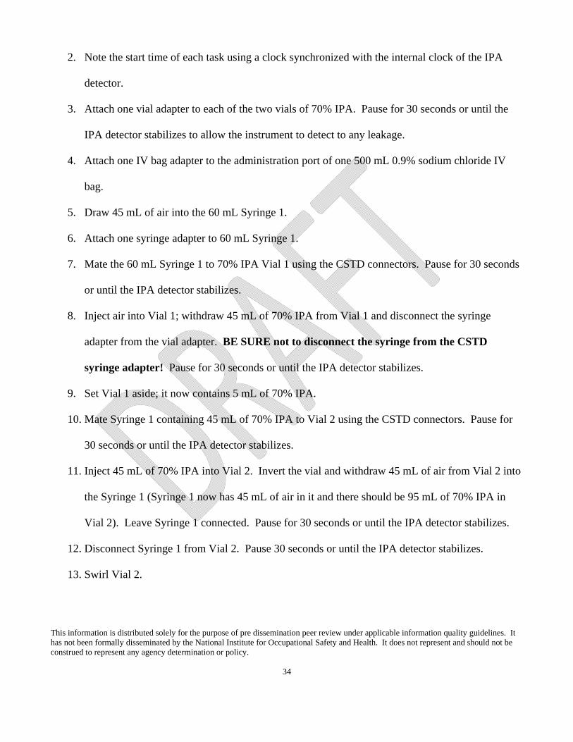
2. Note the start time of each task using a clock synchronized with the internal clock of the IPA
detector.
3. Attach one vial adapter to each of the two vials of 70% IPA. Pause for 30 seconds or until the
IPA detector stabilizes to allow the instrument to detect to any leakage.
4. Attach one IV bag adapter to the administration port of one 500 mL 0.9% sodium chloride IV
bag.
5. Draw 45 mL of air into the 60 mL Syringe 1.
6. Attach one syringe adapter to 60 mL Syringe 1.
7. Mate the 60 mL Syringe 1 to 70% IPA Vial 1 using the CSTD connectors. Pause for 30 seconds
or until the IPA detector stabilizes.
8. Inject air into Vial 1; withdraw 45 mL of 70% IPA from Vial 1 and disconnect the syringe
adapter from the vial adapter. BE SURE not to disconnect the syringe from the CSTD
syringe adapter! Pause for 30 seconds or until the IPA detector stabilizes.
9. Set Vial 1 aside; it now contains 5 mL of 70% IPA.
10. Mate Syringe 1 containing 45 mL of 70% IPA to Vial 2 using the CSTD connectors. Pause for
30 seconds or until the IPA detector stabilizes.
11. Inject 45 mL of 70% IPA into Vial 2. Invert the vial and withdraw 45 mL of air from Vial 2 into
the Syringe 1 (Syringe 1 now has 45 mL of air in it and there should be 95 mL of 70% IPA in
Vial 2). Leave Syringe 1 connected. Pause for 30 seconds or until the IPA detector stabilizes.
12. Disconnect Syringe 1 from Vial 2. Pause 30 seconds or until the IPA detector stabilizes.
13. Swirl Vial 2.
This information is distributed solely for the purpose of pre dissemination peer review under applicable information quality guidelines. It has not been formally disseminated by the National Institute for Occupational Safety and Health. It does not represent and should not be construed to represent any agency determination or policy.
35
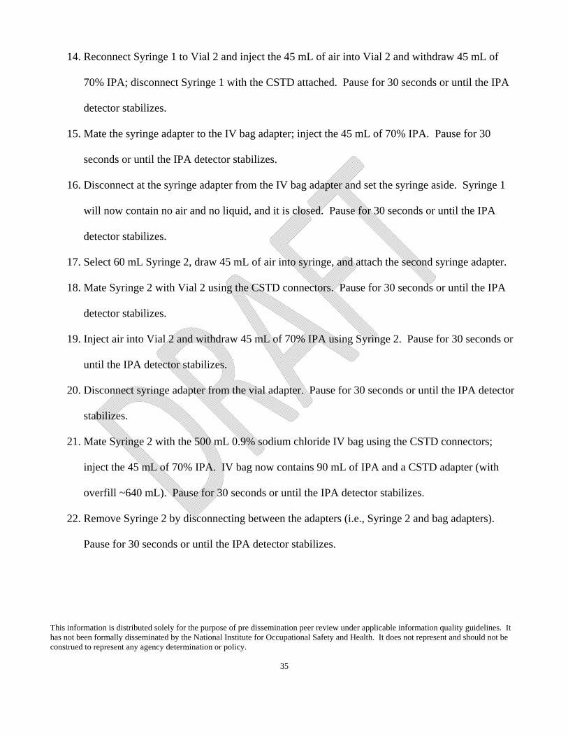
14. Reconnect Syringe 1 to Vial 2 and inject the 45 mL of air into Vial 2 and withdraw 45 mL of
70% IPA; disconnect Syringe 1 with the CSTD attached. Pause for 30 seconds or until the IPA
detector stabilizes.
15. Mate the syringe adapter to the IV bag adapter; inject the 45 mL of 70% IPA. Pause for 30
seconds or until the IPA detector stabilizes.
16. Disconnect at the syringe adapter from the IV bag adapter and set the syringe aside. Syringe 1
will now contain no air and no liquid, and it is closed. Pause for 30 seconds or until the IPA
detector stabilizes.
17. Select 60 mL Syringe 2, draw 45 mL of air into syringe, and attach the second syringe adapter.
18. Mate Syringe 2 with Vial 2 using the CSTD connectors. Pause for 30 seconds or until the IPA
detector stabilizes.
19. Inject air into Vial 2 and withdraw 45 mL of 70% IPA using Syringe 2. Pause for 30 seconds or
until the IPA detector stabilizes.
20. Disconnect syringe adapter from the vial adapter. Pause for 30 seconds or until the IPA detector
stabilizes.
21. Mate Syringe 2 with the 500 mL 0.9% sodium chloride IV bag using the CSTD connectors;
inject the 45 mL of 70% IPA. IV bag now contains 90 mL of IPA and a CSTD adapter (with
overfill ~640 mL). Pause for 30 seconds or until the IPA detector stabilizes.
22. Remove Syringe 2 by disconnecting between the adapters (i.e., Syringe 2 and bag adapters).
Pause for 30 seconds or until the IPA detector stabilizes.
This information is distributed solely for the purpose of pre dissemination peer review under applicable information quality guidelines. It has not been formally disseminated by the National Institute for Occupational Safety and Health. It does not represent and should not be construed to represent any agency determination or policy.
36
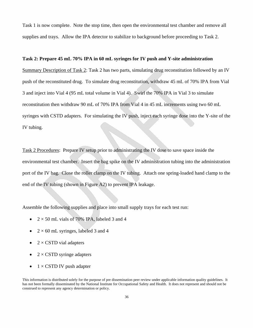
Task 1 is now complete. Note the stop time, then open the environmental test chamber and remove all
supplies and trays. Allow the IPA detector to stabilize to background before proceeding to Task 2.
Task 2: Prepare 45 mL 70% IPA in 60 mL syringes for IV push and Y-site administration
Summary Description of Task 2: Task 2 has two parts, simulating drug reconstitution followed by an IV
push of the reconstituted drug. To simulate drug reconstitution, withdraw 45 mL of 70% IPA from Vial
3 and inject into Vial 4 (95 mL total volume in Vial 4). Swirl the 70% IPA in Vial 3 to simulate
reconstitution then withdraw 90 mL of 70% IPA from Vial 4 in 45 mL increments using two 60 mL
syringes with CSTD adapters. For simulating the IV push, inject each syringe dose into the Y-site of the
IV tubing.
Task 2 Procedures: Prepare IV setup prior to administrating the IV dose to save space inside the
environmental test chamber. Insert the bag spike on the IV administration tubing into the administration
port of the IV bag. Close the roller clamp on the IV tubing. Attach one spring-loaded hand clamp to the
end of the IV tubing (shown in Figure A2) to prevent IPA leakage.
Assemble the following supplies and place into small supply trays for each test run:
2 × 50 mL vials of 70% IPA, labeled 3 and 4
2 × 60 mL syringes, labeled 3 and 4
2 × CSTD vial adapters
2 × CSTD syringe adapters
1 × CSTD IV push adapter
This information is distributed solely for the purpose of pre dissemination peer review under applicable information quality guidelines. It has not been formally disseminated by the National Institute for Occupational Safety and Health. It does not represent and should not be construed to represent any agency determination or policy.
37
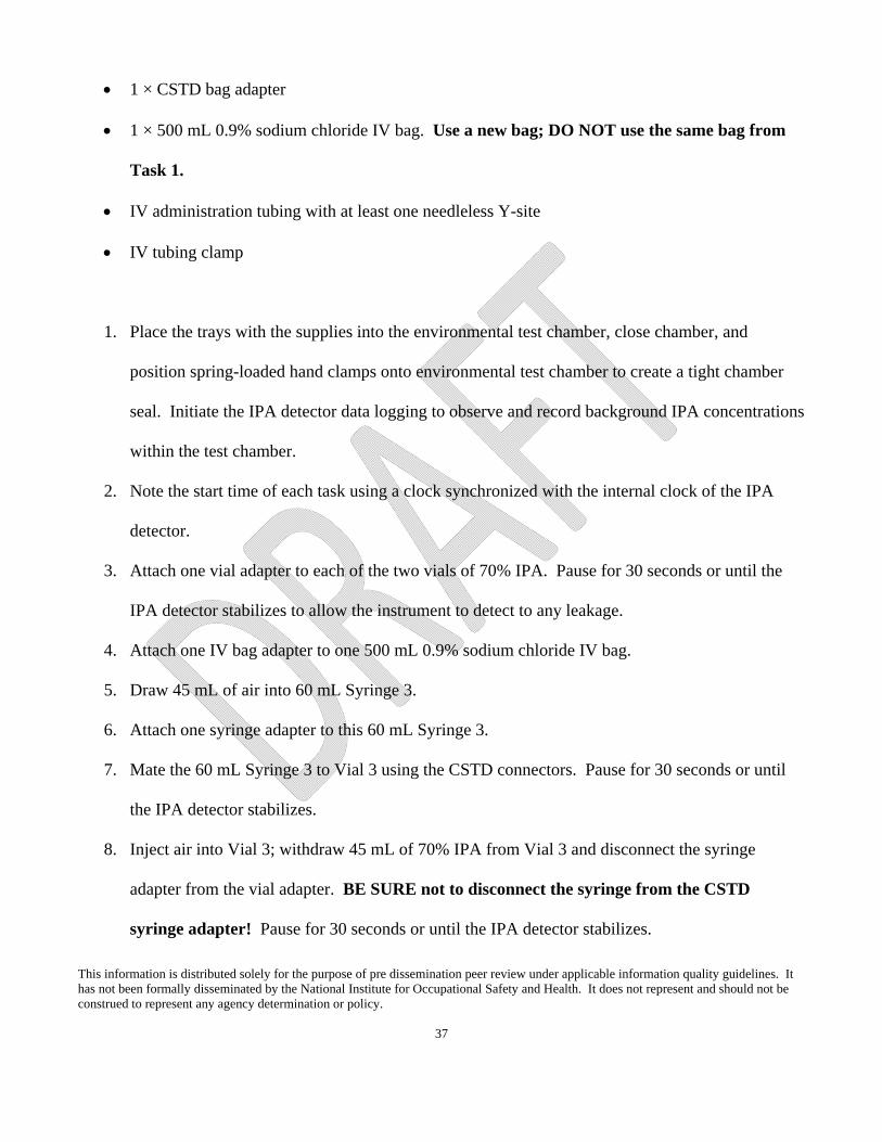
1 × CSTD bag adapter
1 × 500 mL 0.9% sodium chloride IV bag. Use a new bag; DO NOT use the same bag from
Task 1.
IV administration tubing with at least one needleless Y-site
IV tubing clamp
1. Place the trays with the supplies into the environmental test chamber, close chamber, and
position spring-loaded hand clamps onto environmental test chamber to create a tight chamber
seal. Initiate the IPA detector data logging to observe and record background IPA concentrations
within the test chamber.
2. Note the start time of each task using a clock synchronized with the internal clock of the IPA
detector.
3. Attach one vial adapter to each of the two vials of 70% IPA. Pause for 30 seconds or until the
IPA detector stabilizes to allow the instrument to detect to any leakage.
4. Attach one IV bag adapter to one 500 mL 0.9% sodium chloride IV bag.
5. Draw 45 mL of air into 60 mL Syringe 3.
6. Attach one syringe adapter to this 60 mL Syringe 3.
7. Mate the 60 mL Syringe 3 to Vial 3 using the CSTD connectors. Pause for 30 seconds or until
the IPA detector stabilizes.
8. Inject air into Vial 3; withdraw 45 mL of 70% IPA from Vial 3 and disconnect the syringe
adapter from the vial adapter. BE SURE not to disconnect the syringe from the CSTD
syringe adapter! Pause for 30 seconds or until the IPA detector stabilizes.
This information is distributed solely for the purpose of pre dissemination peer review under applicable information quality guidelines. It has not been formally disseminated by the National Institute for Occupational Safety and Health. It does not represent and should not be construed to represent any agency determination or policy.
38
9. Set Vial 3 aside—it now contains 5 mL of 70% IPA.
10. Mate Syringe 3 with 45 mL of 70% IPA to Vial 4 using the CSTD connectors. Pause for 30
seconds or until the IPA detector stabilizes.
11. Inject 45 mL of 70% IPA into Vial 4. Invert the vial and withdraw 45 mL of air from Vial 4 into
the Syringe 3 (Syringe 3 now has 45 mL of air in it and there should be 95 mL of 70% IPA in
Vial 4). Leave syringe connected. Pause for 30 seconds or until the IPA detector stabilizes.
12. Disconnect Syringe 3 from Vial 4. Pause 30 seconds or until the IPA detector stabilizes.
13. Swirl Vial 4.
14. Reconnect Syringe 3 to Vial 4 and inject the 45 mL of air into Vial 4 and withdraw 45 mL of
70% IPA; disconnect Syringe 3 with the CSTD attached. This syringe now contains 45 mL of
70% IPA to administer later into the IV administration set. Pause for 30 seconds or until the IPA
detector stabilizes.
15. Draw 45 mL of air into 60 mL Syringe 4 and attach the syringe adapter.
16. Mate Syringe 4 with Vial 4 using the CSTD connectors. Pause for 30 seconds or until the IPA
detector stabilizes.
17. Inject air into Vial 4 and withdraw 45 mL of 70% IPA using Syringe 4. Pause for 30 seconds or
until the IPA detector stabilizes.
18. Disconnect syringe adapter from the vial adapter. Syringe 4 now contains 45 mL of 70% IPA to
administer later into the IV administration set. Pause for 30 seconds or until the IPA detector
stabilizes.
19. Check that the roller clamps on IV administration tubing are closed, including the ones to the Y-
site and below.

This information is distributed solely for the purpose of pre dissemination peer review under applicable information quality guidelines. It has not been formally disseminated by the National Institute for Occupational Safety and Health. It does not represent and should not be construed to represent any agency determination or policy.
39
20. Take the cover off the spike of the IV administration tubing and open the infusion port on the
bag adapter of the 500 mL 0.9% sodium chloride IV bag.
21. Insert the tubing spike into the port of the bag adapter affixed to the 500 mL 0.9% sodium
chloride IV bag. Pause for 30 seconds or until the IPA detector stabilizes.
22. Gently squeeze the 500 mL 0.9% sodium chloride IV bag to verify there is flow into the drip
chamber.
23. Attach the IV push adapter into the Y-Site. Attach Syringe 3 dose (45 mL of 70% IPA in 60 mL
syringe) with syringe adapter already connected (from step 14) to the push adapter. Pause for 30
seconds or until the IPA detector stabilizes.
24. Open all IV administration tubing roller clamps below the Y-site, and push the first “syringe
dose” from Syringe 3 through the IV push adapter and tubing into the 500 mL 0.9% sodium
chloride IV bag until the Syringe 3 is empty. Pause for 30 seconds or until the IPA detector
stabilizes.
25. Remove Syringe 3 by disconnecting between the adapters (i.e., Syringe 3 and IV push adapters).
Pause for 30 seconds or until the IPA detector stabilizes.
26. Select Syringe 4 for the second “syringe dose” (45 mL of 70% IPA in 60 mL syringe) with
syringe adapter already connected (from step 18) and attach it to the push adapter. Pause for 30
seconds or until the IPA detector stabilizes.
27. Push the second “syringe dose” from Syringe 4 through the IV push adapter and tubing into the
500 mL 0.9% sodium chloride IV bag until the syringe is empty. Pause for 30 seconds or until
the IPA detector stabilizes.
This information is distributed solely for the purpose of pre dissemination peer review under applicable information quality guidelines. It has not been formally disseminated by the National Institute for Occupational Safety and Health. It does not represent and should not be construed to represent any agency determination or policy.
40
28. Remove Syringe 4 by disconnecting between the adapters (i.e., Syringe 4 and IV push adapters).
Pause for 30 seconds or until the IPA detector stabilizes.
29. Close all IV administration tubing roller clamps.
Task 2 is now complete. Note the stop time, then open the environmental test chamber and remove all
supplies and trays. Allow the IPA detector to stabilize to background before proceeding with repetitions
of Task 1 and Task 2.
Data Analysis
The data analyses may be most easily conducted using common spreadsheet programs, such as
Microsoft Excel. Advanced statistical programming is not required. Download the recorded data from
the IPA detector as instructed in the instrument’s operating manual. Evaluate the observed BG
concentrations from the 5 seconds of IPA concentration data recorded immediately prior to the start of
each test run. Calculate the mean of these BG observations, ignoring any BG reading that is below the
instrument’s LOD. Subtract this mean BG concentration from each concentration data point collected
during the test run to create BG-adjusted test data. If all five of the BG observations were below the
instrument’s LOD, then there is no BG-correction. After performing the BG adjustment, if any of the
BG-adjusted data are below zero, then reset these values to zero. This will result in BG-adjusted, zero-
corrected (BG-0) concentration data for each test run. The maximum BG-0 data point (BG-0max) is the
performance metric of interest for each test run. If all data observations during the actual test run are
less than the instrument’s LOD, then consider the maximum value metric representing that test run to be
equal to the instrument’s LOD. The test runs for both Task 1 and Task 2 should be repeated three times

This information is distributed solely for the purpose of pre dissemination peer review under applicable information quality guidelines. It has not been formally disseminated by the National Institute for Occupational Safety and Health. It does not represent and should not be construed to represent any agency determination or policy.
41
for a total of four repetitions. Thus, the resulting data analysis will result in four BG-0max values for
each Task. Calculate the mean of these four BG-0max values as the overall Task performance metric.
This information is distributed solely for the purpose of pre dissemination peer review under applicable information quality guidelines. It has not been formally disseminated by the National Institute for Occupational Safety and Health. It does not represent and should not be construed to represent any agency determination or policy.
42
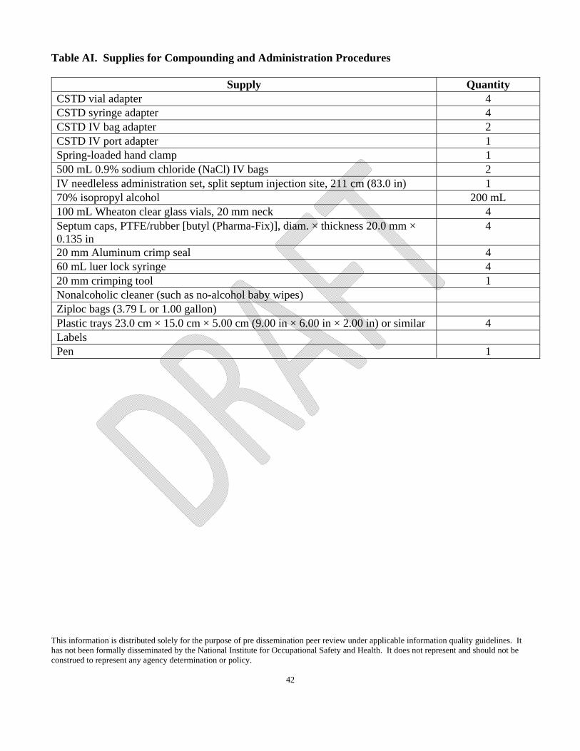
Table AI. Supplies for Compounding and Administration Procedures
Supply Quantity CSTD vial adapter 4 CSTD syringe adapter 4 CSTD IV bag adapter 2 CSTD IV port adapter 1 Spring-loaded hand clamp 1 500 mL 0.9% sodium chloride (NaCl) IV bags 2 IV needleless administration set, split septum injection site, 211 cm (83.0 in) 1 70% isopropyl alcohol 200 mL 100 mL Wheaton clear glass vials, 20 mm neck 4 Septum caps, PTFE/rubber [butyl (Pharma-Fix)], diam. × thickness 20.0 mm × 0.135 in
4
20 mm Aluminum crimp seal 4 60 mL luer lock syringe 4 20 mm crimping tool 1 Nonalcoholic cleaner (such as no-alcohol baby wipes) Ziploc bags (3.79 L or 1.00 gallon) Plastic trays 23.0 cm × 15.0 cm × 5.00 cm (9.00 in × 6.00 in × 2.00 in) or similar 4 Labels Pen 1
This information is distributed solely for the purpose of pre dissemination peer review under applicable information quality guidelines. It has not been formally disseminated by the National Institute for Occupational Safety and Health. It does not represent and should not be construed to represent any agency determination or policy.
43
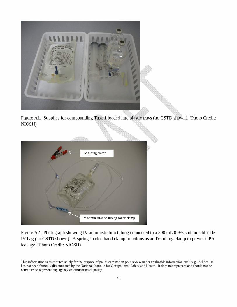
Figure A1. Supplies for compounding Task 1 loaded into plastic trays (no CSTD shown). (Photo Credit: NIOSH)
Figure A2. Photograph showing IV administration tubing connected to a 500 mL 0.9% sodium chloride IV bag (no CSTD shown). A spring-loaded hand clamp functions as an IV tubing clamp to prevent IPA leakage. (Photo Credit: NIOSH)
IV administration tubing roller clamp
IV tubing clamp

This information is distributed solely for the purpose of pre dissemination peer review under applicable information quality guidelines. It has not been formally disseminated by the National Institute for Occupational Safety and Health. It does not represent and should not be construed to represent any agency determination or policy.
44
Appendix B—Materials and Assembly of Environmental Test Chamber
The following modifications apply to a Secador® Techni-dome® 360 vacuum desiccator (or the
Environmental Test Chamber) to result in the NIOSH-developed environmental test chamber for the
vapor containment performance protocol. Table BI is a materials list of parts required to make the
necessary modifications. Figures B1 and B2 are exploded diagrams of the base and chamber
components of the environmental test chamber. It is important to size the male tube adapter to the
diameter of the IPA detector’s sampling hose. The following instructions for the male tube adapter and
relevant drill taps are specific to the IPA detector (Miran SapphIRe model 205B-XL) used during the
NIOSH CSTD testing. For final assembly, use PVC cement to secure all PVC slip-fit connections. The
environmental test chamber is modified and assembled in the following order:
1. Drill 2.50 cm (1 in) hole in the center of one of the four 30.0 cm (12.0 in) wood pieces (Part
Number 1 in Table BI) as shown in Figure B1. Use wood screws or nails (Part 25) plus wood
glue (Part 26) to assemble all four wood pieces into a square base measuring 34.0 cm x 34.0 cm
x 3.9 cm (13.5 in x 13.5 in x 3.5 in).
2. Drill four 0.16 cm (1/16 in) holes through Part Number 2 and into wood base. Countersink holes
in Part Number 2 using a 0.64 cm (1/4 in) countersink. Using four #8 x 2.54 cm (1.0 in) drywall
screws (Part Number 3), attach Part Number 2 to the wood base. [Figure B1]
3. Drill holes centered into the top and bottom portions of environmental test chamber (Part
Numbers 4 and 5, respectively) for airflow. For the top hole, use a 1.11 cm (7/16 in) drill bit.
Tap threads into this hole using a ¼ in-18 NPT tap. For the bottom, the hole should be 2.50 cm
(1 in). [Note: It is very important that you drill slowly using slight pressure so as not to crack
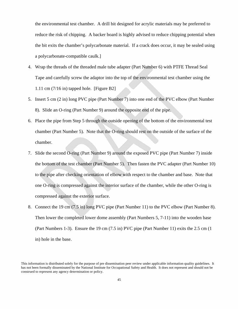
This information is distributed solely for the purpose of pre dissemination peer review under applicable information quality guidelines. It has not been formally disseminated by the National Institute for Occupational Safety and Health. It does not represent and should not be construed to represent any agency determination or policy.
45
the environmental test chamber. A drill bit designed for acrylic materials may be preferred to
reduce the risk of chipping. A backer board is highly advised to reduce chipping potential when
the bit exits the chamber’s polycarbonate material. If a crack does occur, it may be sealed using
a polycarbonate-compatible caulk.]
4. Wrap the threads of the threaded male tube adapter (Part Number 6) with PTFE Thread Seal
Tape and carefully screw the adaptor into the top of the environmental test chamber using the
1.11 cm (7/16 in) tapped hole. [Figure B2]
5. Insert 5 cm (2 in) long PVC pipe (Part Number 7) into one end of the PVC elbow (Part Number
8). Slide an O-ring (Part Number 9) around the opposite end of the pipe.
6. Place the pipe from Step 5 through the outside opening of the bottom of the environmental test
chamber (Part Number 5). Note that the O-ring should rest on the outside of the surface of the
chamber.
7. Slide the second O-ring (Part Number 9) around the exposed PVC pipe (Part Number 7) inside
the bottom of the test chamber (Part Number 5). Then fasten the PVC adapter (Part Number 10)
to the pipe after checking orientation of elbow with respect to the chamber and base. Note that
one O-ring is compressed against the interior surface of the chamber, while the other O-ring is
compressed against the exterior surface.
8. Connect the 19 cm (7.5 in) long PVC pipe (Part Number 11) to the PVC elbow (Part Number 8).
Then lower the completed lower dome assembly (Part Numbers 5, 7-11) into the wooden base
(Part Numbers 1-3). Ensure the 19 cm (7.5 in) PVC pipe (Part Number 11) exits the 2.5 cm (1
in) hole in the base.

This information is distributed solely for the purpose of pre dissemination peer review under applicable information quality guidelines. It has not been formally disseminated by the National Institute for Occupational Safety and Health. It does not represent and should not be construed to represent any agency determination or policy.
46
9. Connect two 5 cm (2 in) long PVC pipes (Part Number 7) to opposite ends of the PVC T-
connector (Part Number 12). Join the pipes (Part Number 7) to the threaded male adapters (Part
Number 13).
10. Wrap the threads of the threaded male pipe adapters (Part Number 13) with PTFE Thread Seal
Tape.
11. Attach filter cartridges (Part Number 14) to threaded male pipe adapters (Part Number 13) to
complete T-assembly.
12. Attach gloves (Part Number 15) to sleeves (Part Number 16) using glove cuff (Part Number 17)
and transition O-rings (Part Number 18). Attach sleeves to ports in environmental test
chamber’s extension piece (Part Number 19) using the larger outer retention bands (Part Number
20) to seal them against the outside of the ports. [Steps 11-16, See Figure B2]
13. Remove the clear gasket supplied with the Secador® Techni-dome® 360 vacuum desiccator
sphere (Part Numbers 4 and 5). Apply foam tape seals (Part Number 21) to the flat mating
circumference of both top and bottom portions of the environmental test chamber. Make sure the
foam tape sits in the groove of environmental test chamber’s top and bottom mating surfaces and
is secured all the way around the circumference of the seal. Verify there is no gap where the tape
ends meet.
14. Place the non-woven filter material (Part Number 22) in the bottom piece of the environmental
test chamber (Part Number 5).
15. Place the 38.0 cm (15.0 in) perforated shelf (Part Number 23) on top of the non-woven filter
material.
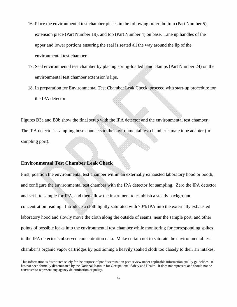
This information is distributed solely for the purpose of pre dissemination peer review under applicable information quality guidelines. It has not been formally disseminated by the National Institute for Occupational Safety and Health. It does not represent and should not be construed to represent any agency determination or policy.
47
16. Place the environmental test chamber pieces in the following order: bottom (Part Number 5),
extension piece (Part Number 19), and top (Part Number 4) on base. Line up handles of the
upper and lower portions ensuring the seal is seated all the way around the lip of the
environmental test chamber.
17. Seal environmental test chamber by placing spring-loaded hand clamps (Part Number 24) on the
environmental test chamber extension’s lips.
18. In preparation for Environmental Test Chamber Leak Check, proceed with start-up procedure for
the IPA detector.
Figures B3a and B3b show the final setup with the IPA detector and the environmental test chamber.
The IPA detector’s sampling hose connects to the environmental test chamber’s male tube adapter (or
sampling port).
Environmental Test Chamber Leak Check
First, position the environmental test chamber within an externally exhausted laboratory hood or booth,
and configure the environmental test chamber with the IPA detector for sampling. Zero the IPA detector
and set it to sample for IPA, and then allow the instrument to establish a steady background
concentration reading. Introduce a cloth lightly saturated with 70% IPA into the externally exhausted
laboratory hood and slowly move the cloth along the outside of seams, near the sample port, and other
points of possible leaks into the environmental test chamber while monitoring for corresponding spikes
in the IPA detector’s observed concentration data. Make certain not to saturate the environmental test
chamber’s organic vapor cartridges by positioning a heavily soaked cloth too closely to their air intakes.

This information is distributed solely for the purpose of pre dissemination peer review under applicable information quality guidelines. It has not been formally disseminated by the National Institute for Occupational Safety and Health. It does not represent and should not be construed to represent any agency determination or policy.
48
If the IPA detector’s concentration baseline remains steady, then the environmental test chamber is
sufficiently airtight. If the concentration fluctuates above the IPA detector’s limit of detection, then
inspect closely and adjust the environmental test chamber as necessary to ensure an airtight fit.
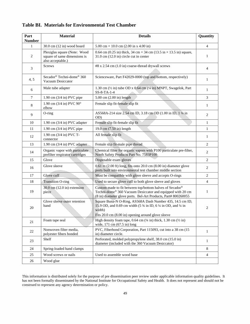
This information is distributed solely for the purpose of pre dissemination peer review under applicable information quality guidelines. It has not been formally disseminated by the National Institute for Occupational Safety and Health. It does not represent and should not be construed to represent any agency determination or policy.
49
Table BI. Materials for Environmental Test Chamber
Part Number
Material Details Quantity
1 30.0 cm (12 in) wood board 5.00 cm × 10.0 cm (2.00 in x 4.00 in) 4
2 Plexiglas square (Note: Wood square of same dimensions is also acceptable.)
0.64 cm (0.25 in) thick, 34 cm × 34 cm (13.5 in × 13.5 in) square, 31.0 cm (12.0 in) circle cut in center 1
3 Screws #8 x 2.54 cm (1.0 in) coarse-thread drywall screws
4
4, 5 Secador® Techni-dome® 360 Vacuum Desiccator
Scienceware, Part F42029-0000 (top and bottom, respectively) 1
6 Male tube adapter 1.30 cm (½ in) tube OD x 0.64 cm (¼ in) MNPT, Swagelok, Part SS-8-TA-1-4
1
7 1.90 cm (3/4 in) PVC pipe 5.00 cm (2.00 in) length 3
8 1.90 cm (3/4 in) PVC 90° elbow
Female slip fit-female slip fit 1
9 O-ring AS568A-214 size 2.54 cm ID, 3.18 cm OD (1.00 in ID, 1 ¼ in OD)
2
10 1.90 cm (3/4 in) PVC adapter Female slip fit-female slip fit 1
11 1.90 cm (3/4 in) PVC pipe 19.0 cm (7.50 in) length 1
12 1.90 cm (3/4 in) PVC T-connector
All female slip fit 1
13 1.90 cm (3/4 in) PVC adapter Female slip fit-male pipe thread 2
14 Organic vapor with particulate prefilter respirator cartridges
Chemical filter for organic vapors with P100 particulate pre-filter, North Safety Products Part No. 7583P100
2
15 Glove Disposable exam gloves 2
16 Glove sleeve 0.61 m (2.00 ft) long, fits onto 20.0 cm (8.00 in) diameter glove ports built into environmental test chamber middle section
2
17 Glove cuff Must be compatible with glove sleeve and accepts O-rings 2
18 Transition O-ring Used to secure glove cuff to both glove sleeve and gloves 4
19 30.0 cm (12.0 in) extension piece
Custom made to fit between top/bottom halves of Secador® Techni-dome® 360 Vacuum Desiccator and equipped with 20 cm (8 in) diameter glove ports. Bel-Art Products, Part# 800260055
1
20
Glove sleeve outer retention band
Square Buna-N O-Ring, AS568A Dash Number 435, 14.5 cm ID, 15.9 OD, and 0.69 cm width (5 ¾ in ID, 6 ¼ in OD, and ¼ in width) Fits 20.0 cm (8.00 in) opening around glove sleeve
2
21 Foam tape seal High density foam tape, 0.64 cm (¼ in) thick, 1.30 cm (½ in) wide, 171 cm (67.5 in) long
22 Nonwoven filter media, polyester fibers bonded
PVC, Fiberbond Corporation, Part 115093, cut into a 38 cm (15 in) diameter circle.
1
23 Shelf Perforated, molded polypropylene shelf, 38.0 cm (15.0 in) diameter (included with the 360 Vacuum Desiccator)
1
24 Spring-loaded hand clamps 8
25 Wood screws or nails Used to assemble wood base 4
26 Wood glue
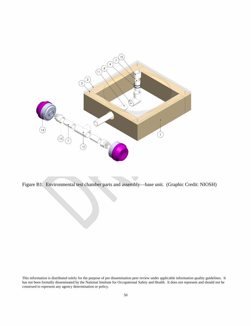
This information is distributed solely for the purpose of pre dissemination peer review under applicable information quality guidelines. It has not been formally disseminated by the National Institute for Occupational Safety and Health. It does not represent and should not be construed to represent any agency determination or policy.
50
Figure B1. Environmental test chamber parts and assembly—base unit. (Graphic Credit: NIOSH)
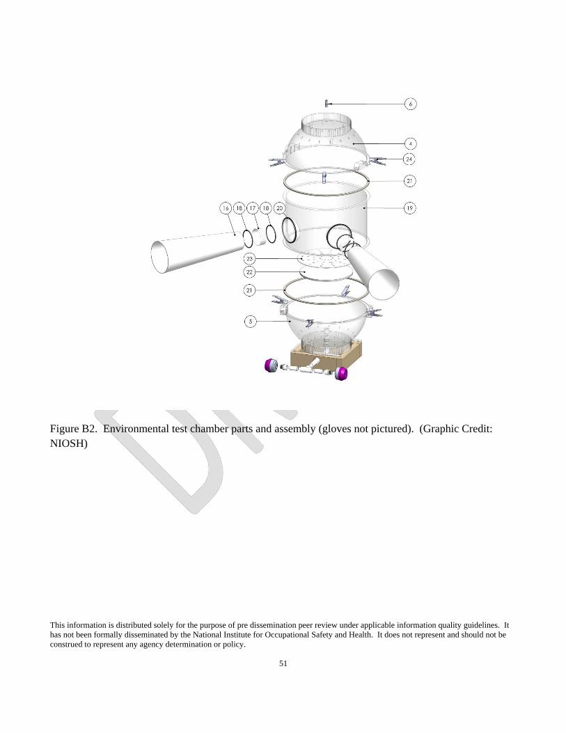
This information is distributed solely for the purpose of pre dissemination peer review under applicable information quality guidelines. It has not been formally disseminated by the National Institute for Occupational Safety and Health. It does not represent and should not be construed to represent any agency determination or policy.
51
Figure B2. Environmental test chamber parts and assembly (gloves not pictured). (Graphic Credit: NIOSH)
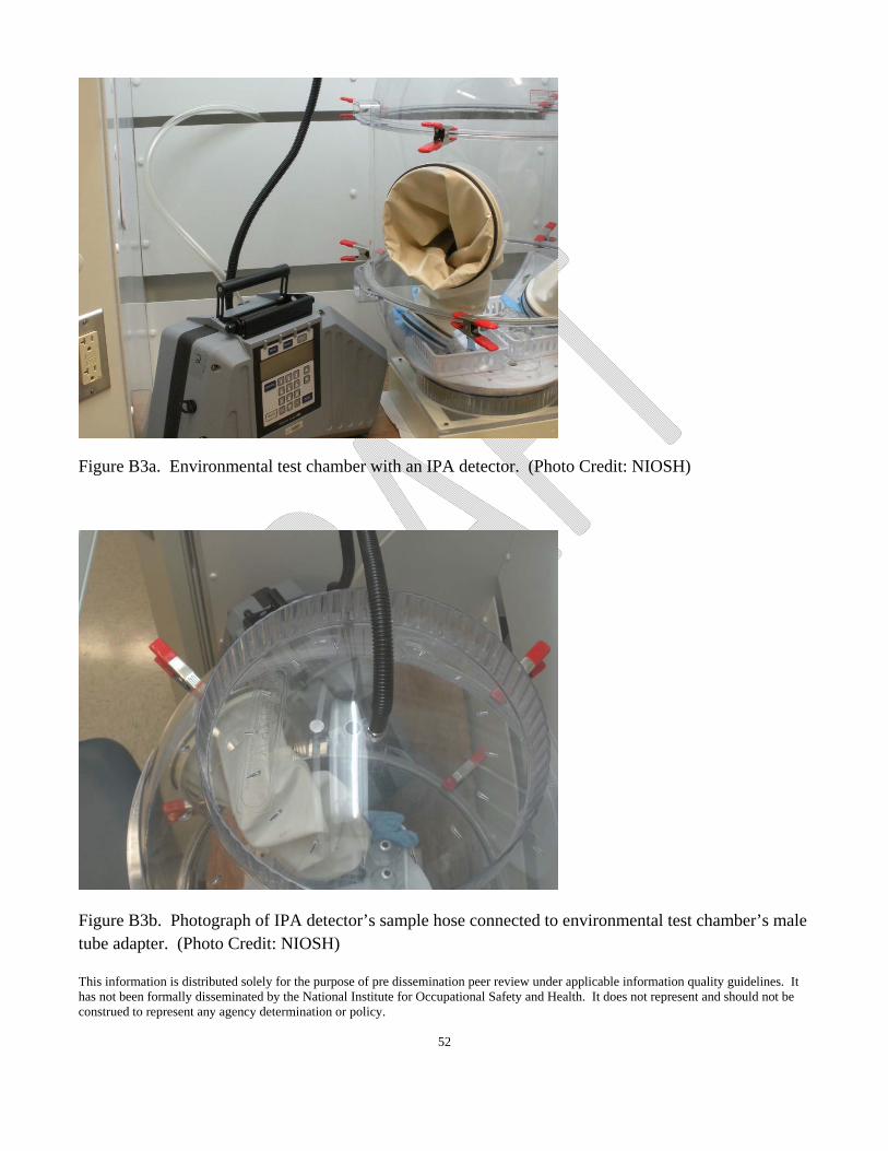
This information is distributed solely for the purpose of pre dissemination peer review under applicable information quality guidelines. It has not been formally disseminated by the National Institute for Occupational Safety and Health. It does not represent and should not be construed to represent any agency determination or policy.
52
Figure B3a. Environmental test chamber with an IPA detector. (Photo Credit: NIOSH)
Figure B3b. Photograph of IPA detector’s sample hose connected to environmental test chamber’s male tube adapter. (Photo Credit: NIOSH)
This information is distributed solely for the purpose of pre dissemination peer review under applicable information quality guidelines. It has not been formally disseminated by the National Institute for Occupational Safety and Health. It does not represent and should not be construed to represent any agency determination or policy.
53
Appendix C—IPA Detector Span Check
Within 24 hours before beginning the test protocol, the IPA detector’s operational response should be
verified by performing a span check with known concentrations of span gas. The intent of the span
check is to confirm operational compatibility of the IPA detector when connected to the environmental
test chamber. The intent is to verify the configuration setup and since some span gases are more easily
acquired than others, it is not imperative that the span gas be IPA. Rather, it is important that the span
gas be a gas and a concentration for which the IPA detector is compatible. Place the zero and span gas
cylinders into the environmental test chamber prior to initiating the zero and span checks. The slightly
modify the manufacturer’s zero and span check procedures for compatibility with the environmental test
chamber. Table CI lists the materials needed for the span check. Instructions of how to perform the
span check are below.
1. Verify that the IPA detector is factory calibrated and within the factory-level calibration period.
2. Activate the IPA detector and allow time for adequate warm up as directed by manufacturer.
3. Zero the IPA detector in accordance with the manufacturer instructions.
4. Follow the IPA detector’s instructions for span procedure (modified slightly to account for
sample inlet positioning at the environmental test chamber’s male tube adaptor) with the known
concentration of span gas in air.
5. Attach regulator and/or gas sampling accessory to span gas cylinder.
6. Initiate span check using the low-concentration span gas then repeat with the high-concentration
span gas. Instrument’s display gas readings may take a few minutes to stabilize.
7. Record the instrument concentration readings.
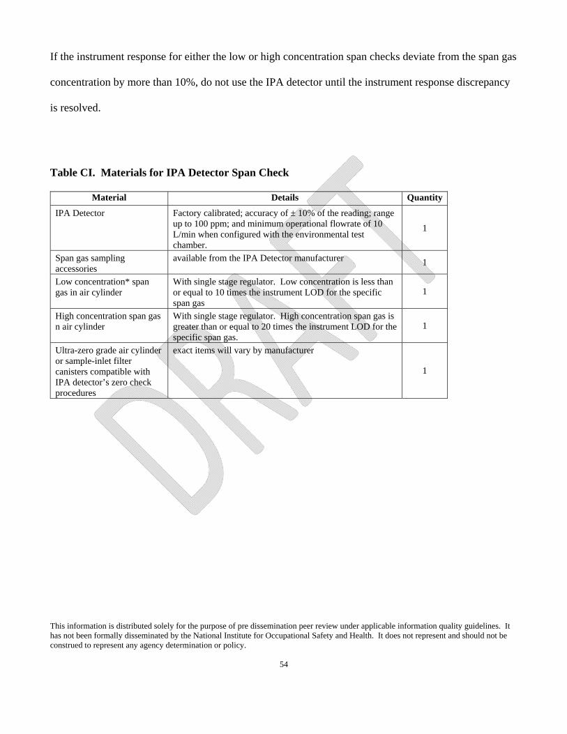
This information is distributed solely for the purpose of pre dissemination peer review under applicable information quality guidelines. It has not been formally disseminated by the National Institute for Occupational Safety and Health. It does not represent and should not be construed to represent any agency determination or policy.
54
If the instrument response for either the low or high concentration span checks deviate from the span gas
concentration by more than 10%, do not use the IPA detector until the instrument response discrepancy
is resolved.
Table CI. Materials for IPA Detector Span Check
Material Details Quantity
IPA Detector Factory calibrated; accuracy of ± 10% of the reading; range up to 100 ppm; and minimum operational flowrate of 10 L/min when configured with the environmental test chamber.
1
Span gas sampling accessories
available from the IPA Detector manufacturer 1
Low concentration* span gas in air cylinder
With single stage regulator. Low concentration is less than or equal to 10 times the instrument LOD for the specific span gas
1
High concentration span gas n air cylinder
With single stage regulator. High concentration span gas is greater than or equal to 20 times the instrument LOD for the specific span gas.
1
Ultra-zero grade air cylinder or sample-inlet filter canisters compatible with IPA detector’s zero check procedures
exact items will vary by manufacturer
1
This information is distributed solely for the purpose of pre dissemination peer review under applicable information quality guidelines. It has not been formally disseminated by the National Institute for Occupational Safety and Health. It does not represent and should not be construed to represent any agency determination or policy.
55
Appendix D—Model Closed System Transfer Device Certification
— [Independent Test Laboratory] hereby certifies that a closed system transfer device [Model Number]
manufactured by [Manufacturing Company] was tested on [Date] in accordance with “Appendix A—
Laboratory Vapor Containment Performance Test Protocol for CSTDs” of the Technical Report, A
Vapor Containment Performance Protocol for Closed System Transfer Devices Used During Pharmacy
Compounding and Administration of Hazardous Drugs, published by the National Institute for
Occupational Safety and Health (NIOSH). During the four repetitions of each prescribed Task
identified in the protocol, the average of the maximum vapor concentrations of isopropyl alcohol
detected to escape from the tested closed system transfer device was X.XX ppm during Task 1 and
Y.YY ppm during Task 2 as measured using (make/model of detection instrument) with a calibration
date of (mm/dd/yyyy) and an instrument limit of detection (LOD) of x.xx ppm of isopropyl alcohol.
[NOTE: Any measured concentration of isopropyl alcohol that is above the instrument’s LOD is simply
an indicator of isopropyl aerosol and/or vapor escape that exceeds that which would escape from a 100%
closed system. Reported measurements greater than 3.33 times the LOD may be interpreted as their
actual concentration value. Any measured IPA concentration has not been correlated with a specific
hazardous drug exposure reduction expected to occur during pharmacy compounding or drug
administration manipulations.]