facially related maxillary occlusal plane transfer · adjust scan data orientation (optional) ......
TRANSCRIPT

2020 © Kois Center, LLC
Kois Digital Transfer Adapter Instructions
WWW.KOISCENTER.COM
2. Adjust Scan Data Orientation (Optional)
• Click “Set current view as axis”• Click “Next”Note: Virtual Articulator will be disabled until thisstep is completed.
1. Import the Upper and Lower Scans as Prompted
FIGURE 1 - Jaw Scan (MX) FIGURE 2 - Antagonist (MN)
FIGURE 3 - Adjust Scan Data Orientation
3. Enter Expert Mode
• Expert mode should be assumed from here on.
4. Tools > Add Picture(s)
Retracted Photo• Click Load image from file• Select the “Retracted Front Facing” photo.• Click the Rescale Tab in 2D Image Loader Menu• Zoom in on one of the target circles.• Click to set the 1st point.• Zoom in on the opposite target circles.• Click to set the 2nd point.• Enter “140” into the desired length text box.• Click “Rescale”• Click “Add Image” Tab.
Tilted Up Photo• Click Load image from file• Select the “Tilted Up” photo.• Click the Rescale Tab in 2D Image Loader Menu• Zoom in on one of the target circle.• Click to set the first point.• Zoom in on the opposite target circles.• Click to set the 2nd point.• Enter “140” into the desired length text box.• Click “Rescale”
• Click “OK”
FIGURE 4 -Retracted Teeth Apart FIGURE 5 - Tilted Up Photo
FIGURE 6 - Point #1 FIGURE 7 - Point #2
Facially Related Maxillary Occlusal Plane Transfer

2020 © Kois Center, LLC
Kois Digital Transfer Adapter Instructions
WWW.KOISCENTER.COM
5. Import Alignment Mesh
• Tools > Add/Remove Mesh Note: Designating it a Generic Visualization Mesh seems to make it easier to align through a photo but is unimportant to the process.
• Click Load• Select the Upper Model• Click Ok• Match Scene (Arbitrary)
6. Save and Close the Project
• Not all meshes are not freely moveable unless the scene is closed and reopened.
7. Re-open the Project File (Load Scene Data)
• The scene should look similar to this.
FIGURE 8 - Alignment Copy (MX)
FIGURE 9 - Jaw Scan (MX)
FIGURE 10 - Scene Assets
2020 © Kois Center, LLC
Kois Digital Transfer Adapter Instructions
WWW.KOISCENTER.COM
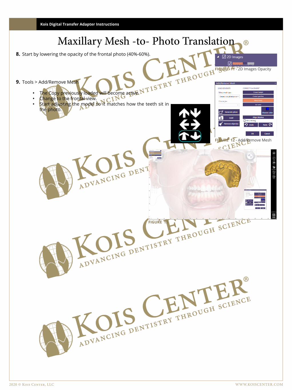
8. Start by lowering the opacity of the frontal photo (40%-60%).
9. Tools > Add/Remove Mesh
• The Copy previously loaded will become active.• Change to the frontal view.• Start adjusting the model so it matches how the teeth sit in
the photo.
FIGURE 11 - 2D Images Opacity
FIGURE 12 - Add/Remove Mesh
FIGURE 13
Maxillary Mesh -to- Photo Translation

2020 © Kois Center, LLC
Kois Digital Transfer Adapter Instructions
WWW.KOISCENTER.COM
11. Rotating the model until some of the for more prominent & easily distinguishable vertical edges are matching up with the same edges in the photo.
12. Move the model further down overlapping 3/4 of the teeth in the photo.
• Keeping the vertical edges lined up.• Begin matching the horizontal edges by adjusting
the Roll and Pitch of the model.
FIGURE 14 - 1st Pass Alignment
10. Move the model just above the teeth in the photo.
FIGURE 15 - 1st Pass Alignment
FIGURE 16 - 2nd Pass Alignment
FIGURE 17 - 2nd Pass Alignment
FIGURE 18 - 3rd Pass Alignment
13. Bring the model down until it is completely over the photo teeth.

2020 © Kois Center, LLC
Kois Digital Transfer Adapter Instructions
WWW.KOISCENTER.COM
16. Switch to a side view and using the gray arrows, rotate the picture forward until it is matching the angle of the photo.
FIGURE 19 - Antagonist (MN)
14. Tools > Add Picture
• Adjust the opacity of the two photos until both sets of facial reference glasses are visible.
• Verify that the verical line on the facial glasses are aligned between the two images.
• Verify that the horizontal planes of the facial glasses run parrallel between the images.
15. Select the tilted up photo from the loaded images.
• Change to the side view• The tilted photo may only be rotated along the horizontal axis.• This does not require a exact matchuntil it closly matches the angle of the photo.• It may require changing between views • Verify that the verical line on the facial glasses are aligned between the two images.
17. Move the photo down along the axis until the occlusal surface of both images is visible.
• Change to the side view• Verify the vertical rotation of the mesh in relation
to the photo to improve the translation accuracy.
18. Adjustments should only be made from the frontal view.
• If adjustment are to be made, go back to the front facing view and make the adjustments. • Do not adjust the model from tilted photo view. It is only to verify the vertical rotation.
Secondary Angle Verification (Optional)

2020 © Kois Center, LLC
Kois Digital Transfer Adapter Instructions
WWW.KOISCENTER.COM
19. Align Jaw Scan & Antagonist to Alignment Copy
• Set the first point for the floating mesh on the Original Upper Arch and then again on the coresponding spot on the Alignment Copy (Fixed Mesh).
• Set the Second and Third Points.• Once the three points are set, unhide the antagonist and click the “Select additional
floating part” checkbox and select the antagonist from the list.• Click Preform Alignment• Click Best Fit Matching• There should be no decrepencies, as it is the same exact model.• Click Close.
2020 © Kois Center, LLC
Kois Digital Transfer Adapter Instructions
WWW.KOISCENTER.COM
Model Creation with exocadPrep Files1. Virtually Oriented Upper and Lower Scan(s).
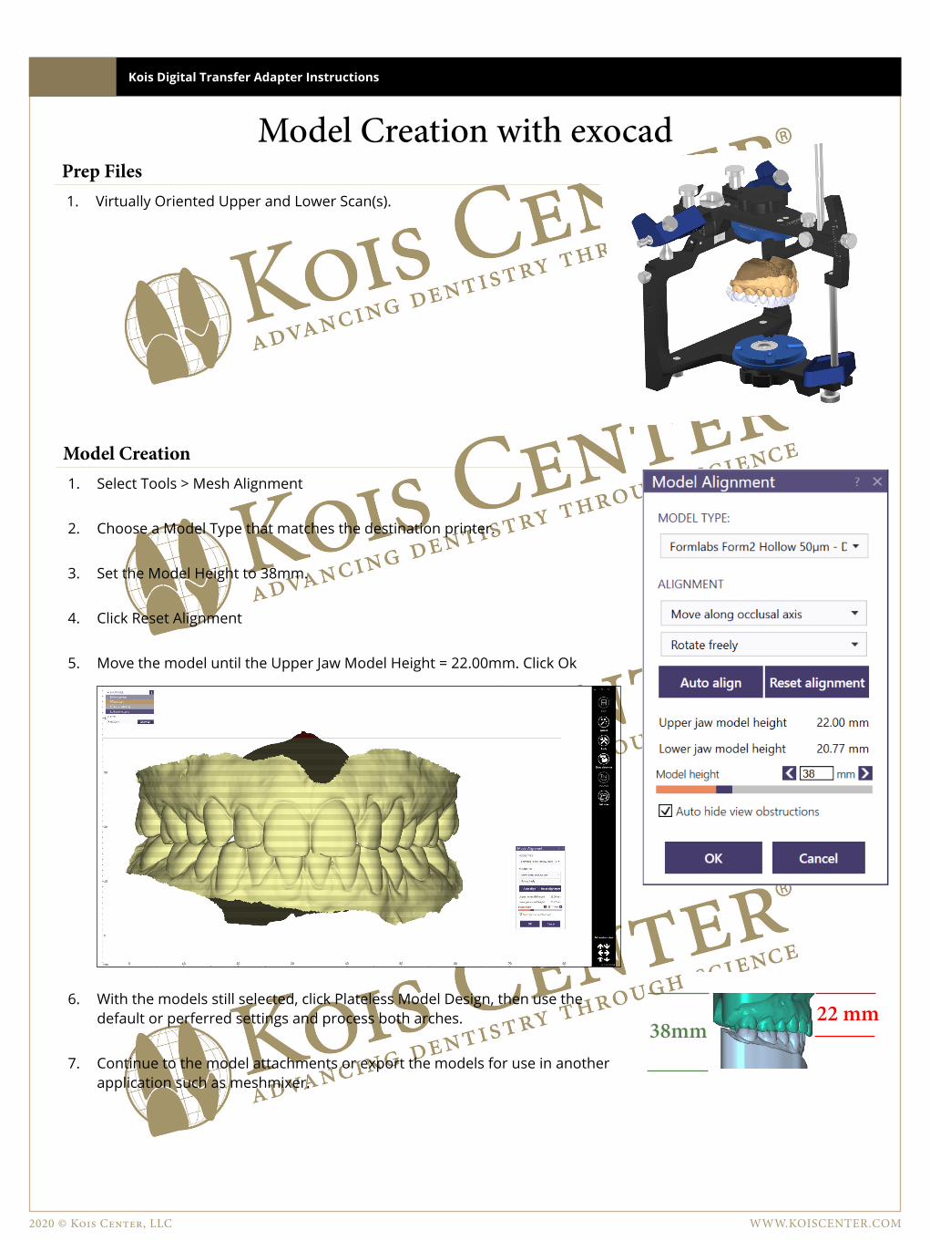
Model Creation1. Select Tools > Mesh Alignment
2. Choose a Model Type that matches the destination printer.
3. Set the Model Height to 38mm.
4. Click Reset Alignment
5. Move the model until the Upper Jaw Model Height = 22.00mm. Click Ok
6. With the models still selected, click Plateless Model Design, then use the default or perferred settings and process both arches.
7. Continue to the model attachments or export the models for use in another application such as meshmixer.
22 mm38mm

2020 © Kois Center, LLC
Kois Digital Transfer Adapter Instructions
WWW.KOISCENTER.COM
Model Attachment with exocadPrep Files1. Virtually Mounted Upper and Lower Scan(s).
2. exocad Model Builder Module.
3. Kois Attachments for exocad model builder. www.koiscenter.com/wp-content/uploads/2020/02/Kois-Attachment-v2.zip
Model Attachment with exocad Model Builder1. Select Tools > Model Attachment
2. Choose the Kois Attachment and click on the back of the upper model.
3. Change to the Top-Down view.
4. Zoom in to the area on the attachment with the pin holes.
5. Hold CTRL and rotate the attachment until it lines up with the grid lines perfectly.
6. Zoom out and drag the attachment so the front area of the attachment is in front of the model.
7. Change to the front-view and move the attachment left/right until the center notch lines up with the midline.
8. Finally change to the side-view and move the model so the front incisal edge is at the 71mm gridline.
9. Next, pull the attachment back until the back edge is at the 0mm gridline.
10. Click Ok to process the attachments.
11. Save the files out and print.
0mm 71mm
FIGURE 1 — Line up the attachment with the gridlines.
FIGURE 2 — Moving the attachment so the center notch is visible from the front.
FIGURE 3 — Lining up the attachment with the facial midline.
FIGURE 4 — Setting the model/attachment length.