lingual orthodontic appliancescodental.uobaghdad.edu.iq/wp-content/uploads/sites/... · generation...
TRANSCRIPT
Republic of Iraq
Ministry of Higher Education
And scientific Research
University of Baghdad
College of Dentistry
Lingual orthodontic
appliances
A project
Submitted to Collage of Dentistry, University of Baghdad.
Department of orthodontics in fulfillment for the requirement of B.D.S degree
Done by
Maryam Jaber Hussein 5th Grade
Supervisor
Lecturer Dr. Ammar Salim
B.D.S, M.S.C (orthodontics)
Baghdad-Iraq
2017-1438

i

ii
Acknowledgement
At the beginning I would like to express my gratitude to my
dear God for his continuous reconcile.
I would like to dedicate this project to Imam Al-Mahdi (Oh Allah
hasten his appearance).
Also I would like to express my special thanks of gratitude to Dr
Hussein Al-Huwaizi , Dr Dhiaa Al-Dabbagh and my supervisor Dr.
Ammar Salim who gave me the golden opportunity to do this wonderful
project on the topic Lingual orthodontic appliance, which also helped me
in doing a lot of research and I came to know about so many new things I
am really thankful to them.
Secondly I would also like to thank my parents, friends and specially my
husband who helped and supported me a lot in finalizing this project
within the limited time frame.
iii
Abstract
The development of lingual orthodontic appliances dates back to the 70‟s
of the past century. A lot of development occurred since then. These
appliances are usually associated with more patient discomfort, more
technically demanding, and greater cost. However, their greatest
advantage is esthetic, being placed on the lingual side of the teeth,
patients can enjoy smiling. The latest advances that depend on
CAD/CAM technology have overcome lots of the problems associated
with the previous lingual appliances, and they can be considered a good
treatment choice when esthetic is a major concern.
iv
List of contents
ACKNOWLEDGEMENT ............................................................................................... II
ABSTRACT ................................................................................................................ III
LIST OF CONTENTS............................................................................................ IV
LIST OF FIGURES ....................................................................................................... VI
INTRODUCTION ..................................................................................................... VIII
AIMS OF THE STUDY ................................................................................................ IX
REVIEW OF LITERATURE............................................................................................ 1
1.1. HISTORY ............................................................................................................. 1
1.2. GENERATION DEVELOPMENT OF LINGUAL APPLIANCE ..................................... 2
1.2.1. GENERATION #1—1976 .................................................................................... 2
1.2.2. GENERATION #2—(1980).................................................................................. 2
1.2.3. GENERATION #3—(1981).................................................................................. 3
1.2.4. GENERATION #4—(1982–1984) ........................................................................ 3
1.2.5. GENERATION #5—(1985–1986) ........................................................................ 4
1.2.6. GENERATION #6—(1987–1990) ........................................................................ 4
1.2.7. GENERATION #7—1990 TO PRESENT .................................................................... 5
1.3. ADVANTAGES OF LINGUAL ORTHODONTICS ..................................................... 5
1.4. DISADVANTAGES ............................................................................................... 6
1.5. MAIN DIFFERENCES BETWEEN LABIAL AND LINGUAL TECHNIQUES: ................. 6
1.5.1. ANATOMIC VARIATIONS OF THE LINGUAL TOOTH SURFACES ........................................ 6
1.5.2. FIRST-ORDER COMPENSATIONS ............................................................................ 7
1.5.1. TORQUE CONTROL............................................................................................. 8
1.5.2. EXPOSURE OF BONDING AREA ............................................................................ 10
1.5.3. EFFICIENT LEVELING AND ALIGNING WITH LINGUAL APPLIANCES ................................... 10
1.5.3.1. Aligning Type 1 11
1.5.3.2 Aligning Type 2 11
1.5.3.3. Aligning Type 3 12
1.6. INDICATIONS AND CONTRA INDICATIONS: ...................................................... 12
1.7. SITUATIONS WHERE LINGUAL APPLIANCES ARE MORE EFFECTIVE THAN LABIAL
APPLIANCES 13
1.7.1. INTRUSION OF ANTERIOR TEETH .......................................................................... 13
1.7.2. MAXILLARY ARCH EXPANSION ............................................................................ 15
1.7.3. COMBINING MANDIBULAR REPOSITIONING THERAPY WITH ORTHODONTIC MOVEMENTS . 16
1.7.4. DISTALIZATION OF MAXILLARY MOLARS ................................................................ 17
1.8. PROBLEM ASSOCIATED WITH LINGUAL APPLIANCE ......................................... 17
v
1.8.1. TISSUE IRRITATION AND SPEECH DIFFICULTIES ........................................................ 17
1.8.2. GINGIVAL IMPINGEMENT ................................................................................... 17
1.8.3. OCCLUSAL INTERFERENCE .................................................................................. 18
1.8.4. APPLIANCE CONTROL ....................................................................................... 19
1.8.5. BASE PAD ADAPTATION .................................................................................... 19
1.8.6. APPLIANCE PLACEMENT AND BONDING................................................................. 19
1.8.7. APPLIANCE PRESCRIPTION ................................................................................. 20
1.8.8. WIRE PLACEMENT ........................................................................................... 21
1.8.9. LIGATION ...................................................................................................... 21
1.8.10 ATTACHMENTS ............................................................................................. 22
1.9. BONDING IN LINGUAL ORTHODONTIC APPLIANCE .......................................... 22
1.9.1. INDIRECT BONDING .......................................................................................... 22
1.10. THE INCOGNITO LINGUAL APPLIANCE ........................................................... 25
1.10.1. PROBLEMS ................................................................................................... 29
1.10.1.1. Patient difficulties during the adaptation stage....................... 29
1.10.1.2. Difficulties with exact rebonding in the event of bracket loss ............ 30
1.10.1.3.Exact finishing ....................................... 31
CONCLUSIONS......................................................................................................... 33
REFERENCE.............................................................................................................. 34

vi
List of figures
FIGURE 1. GENERATION #1—1976 FLAT MAXILLARY OCCLUSAL BITE PLANE FROM CANINE TO CANINE
THE LOWER ANTERIORS AND PREMOLARS HAD LOW PROFILE, HALF-ROUND BRACKETS. THERE
WERE NO HOOKS ON ANY BRACKETS. ............................................................................ 2
FIGURE 2 GENERATION #2—1980. HOOKS WERE ADDED TO ALL CANINE BRACKETS. ...................... 2
FIGURE 3 GENERATION #3—1981. HOOKS WERE ADDED TO ALL ANTERIOR AND PREMOLAR BRACKETS.
........................................................................................................................... 3
FIGURE 4 GENERATION #4— ADDITION OF A LOW PROFILE ANTERIOR INCLINED PLANE ON THE CENTRAL
AND LATERAL INCISORS. HOOKS WERE OPTIONAL. ............................................................ 3
FIGURE 5 GENERATION #5—1985–86. A TRANSPALATAL BAR ATTACHMENT WAS NOW AVAILABLE
FOR THE FIRST MOLAR BRACKET. .................................................................................. 4
FIGURE 6 GENERATION #6—1987–90. THE INCLINED PLANE ON THE MAXILLARY ANTERIORS BECAME
MORE SQUARE IN SHAPE. ........................................................................................... 4
FIGURE 7 GENERATION #7—1990–PRESENT. THE MAXILLARY ANTERIOR INCLINED PLANE IS HEART-
SHAPED WITH SHORT HOOKS. THE LOWER ANTERIOR BRACKETS HAVE A LARGER INCLINED PLANE
WITH SHORT HOOKS AND ALL HOOKS HAVE A GREATER RECESS/ACCESS FOR LIGATION. .............. 5
FIGURE 8 A SLIGHTLY DIFFERENT POSITIONING HEIGHT OF THE BRACKET HAS ONLY A SMALL IMPACT ON
TORQUE (2 DEGREES) WITH A LABIAL APPLIANCE. ON THE LINGUAL ASPECT, THE SAME HEIGHT
DIFFERENCE RESULTS IN A MAJOR TORQUE DIFFERENCE (22 DEGREES)................................... 7
FIGURE 9 A, DIFFERENT TOOTH THICKNESSES ARE COMPENSATED BY FIRST-ORDER ARCHWIRE BENDS. B,
THE ARCHWIRE IS STRAIGHT. C, MUSHROOM ARCH FORM. D, SUPERPOSITION OF THE THREE
TYPES OF ARCHWIRES. .............................................................................................. 9
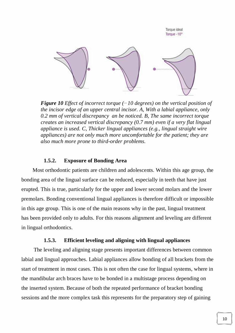
FIGURE 10 EFFECT OF INCORRECT TORQUE (−10 DEGREES) ON THE VERTICAL POSITION OF THE INCISOR
EDGE OF AN UPPER CENTRAL INCISOR. A, WITH A LABIAL APPLIANCE, ONLY 0.2 MM OF VERTICAL
DISCREPANCY AN BE NOTICED. B, THE SAME INCORRECT TORQUE CREATES AN INCREASED
VERTICAL DISCREPANCY (0.7 MM) EVEN IF A VERY FLAT LINGUAL APPLIANCE IS USED. C, THICKER
LINGUAL APPLIANCES (E.G., LINGUAL STRAIGHT WIRE APPLIANCES) ARE NOT ONLY MUCH MORE
UNCOMFORTABLE FOR THE PATIENT; THEY ARE ALSO MUCH MORE PRONE TO THIRD-ORDER
PROBLEMS. .......................................................................................................... 10
FIGURE 11 ALIGNING TYPE1 ........................................................................................... 11
FIGURE 12 ALIGNING TYPE 2 .......................................................................................... 11
FIGURE 13 ALIGNING TYPE 3 ........................................................................................... 12
FIGURE 14 . THE CENTER OF RESISTANCE OF THE TOOTH IS LOCATED CLOSER TO THE LINGUAL BRACKET
......................................................................................................................... 14
FIGURE 15 OCCLUSAL VIEW OF THE MANDIBULAR ARCH, JUST AFTER THE PARTIAL LINGUAL BONDING;
THE MOLARS WERE BANDED AFTERWARDS) .................................................................. 14
FIGURE 16 (LEFT) THE UPPER ARCH (OCCLUSAL VIEW), JUST AFTER PLACING THE FIRST SUPERELASTIC
TWIST-FLEX TYPE ARCHWIRE. (RIGHT) FOUR MONTHS LATER, NOTICE THE AMOUNT OF THE
TRANSVERSE AND SAGITTAL EXPANSION....................................................................... 15
FIGURE 17 LEFT INTRAORAL VIEW DURING THE LAST PHASES OF THE CLASS II MECHANICS ............... 16
FIGURE 18 INITIALLY, ANTERIOR BRACKETS HAD LONG GINGIVAL HOOKS RESPONSIBLE FOR CALCULUS
BUILD-UP. ........................................................................................................... 18

vii
FIGURE 19 THE INCLINE PLANE. THE RED ARROWS REPRESENT THE PRIMARY FORCE APPLIED, AND THE
BROKEN BLACK LINES REPRESENT THE SECONDARY/RESULTANT FORCES EXERTED .................... 18
FIGURE 20 LOCKING OF THE MOLARS TO THE LINGUAL ATTACHMENT WAS THOUGHT TO GIVE GREATER
APPLIANCE CONTROL. ............................................................................................. 19
FIGURE 21 WIDENING OF THE MESIAL APERTURE TO PROVIDE EASE OF WIRE INSERTION. ................ 21
FIGURE 22 FRONTAL VIEW OF THE LINGUAL BRACKET DESIGNED FOR THE MAXILLARY ..................... 21
FIGURE 23 A LOW-SPEED HANDPIECE WITH A CLEANSING BRUSH IS RECOMMENDED ..................... 22
FIGURE 24 CHEEK, LIP, AND TONGUE RETRACTORS ............................................................... 23
FIGURE 25 AFTER THE PLACEMENT OF 37 % PHOSPHORIC ACID GEL .......................................... 23
FIGURE 26 A DRY AIR SYRINGE IS USEFUL TO OBTAIN A FROSTY ENAMEL SURFACE ......................... 24
FIGURE 27 LIGHT-CURE BONDING AGENT ADHESIVE IN PLACE .................................................. 24
FIGURE 28 MOLAR TRANSFERRING CAP IN PLACE .................................................................. 25
FIGURE 29 EASY METHOD TO REMOVE THE INDIVIDUAL TRANSFER CAP ...................................... 25
FIGURE 30 CONTEMPORARY UPPER LINGUAL APPLIANCE AND CONTEMPORARY LOWER LINGUAL
APPLIANCE. .......................................................................................................... 25
FIGURE 31 TWO-PHASE POLYVINYL SILOXANE IMPRESSIONS ARE TAKEN TO PRODUCE ACCURATE MODELS
OF THE PATIENT’S TEETH. ......................................................................................... 26
FIGURE 32 3D DIGITAL REPRESENTATION OF A TOOTH FROM THE TARGET SETUP. ARCH.................. 27
FIGURE 33 THE VIRTUAL BRACKETS CONFORM EXACTLY TO THE INDIVIDUAL PATIENT’S DENTAL
MORPHOLOGY. ..................................................................................................... 27
FIGURE 34 THE VIRTUAL BRACKETS ARE NOW A REALITY IN WAX (WAX PATTERNS) PRIOR TO CASTING. 27
FIGURE 35 COMPLETE SET OF VIRTUAL BRACKETS CONSTRUCTED FOR AN INDIVIDUAL’S MAXILLARY ... 27
FIGURE 36 THE FINAL BRACKETS AFTER INVESTMENT CASTING, THE POLISHED GOLD BRACKETS ARE
PLACED ON THE ORIGINAL MALOCCLUSION MODEL. ........................................................ 28
FIGURE 37 AN INDIRECT BONDING TRAY CONTAINING THE BRACKETS. (THE FITTING SURFACES OF THE
LINGUAL BRACKETS ARE A DARK COLOR DUE TO THE APPLICATION OF BONDING MATERIALS.)..... 28
FIGURE 38 COMPARISON OF A CONVENTIONAL LINGUAL BRACKET (LEFT) WITH INCOGNITO BRACKET
(RIGHT) SHOWS A PRONOUNCED DIFFERENCE IN SIZE. ..................................................... 30
FIGURE 39 SCREENSHOTS OF THE 3D REPRESENTATION OF THE POSITIONED BRACKETS FROM VARIOUS
ANGLES (AS ABOVE) SERVE AS AN ADDITIONAL REBONDING AID. ........................................ 30
FIGURE 40 : INCORRECT TORQUE WILL CAUSE VERTICAL DISCREPANCIES IN THE POSITION OF THE INCISAL
EDGES. ............................................................................................................... 31

viii
Introduction
Lingual orthodontics as we understand it today began in the 1970s.
A Japanese orthodontist, Dr Kinja Fujita, developed the appliance, not
primarily for aesthetic reasons but rather to protect the soft tissues (lips
and cheeks) of his orthodontic patients who practiced martial arts.
Independently, in the USA, Dr Craven Kurz worked to develop a lingual
appliance at this time. The first lingual appliances used standard labial
brackets, which were modified by the clinician and bonded to the teeth
using a direct technique, the same technique as is employed to bond labial
brackets. Lingual orthodontics achieved a certain amount of popularity in
the 1980s; however, its popularity soon decreased due to clinical
difficulties associated with the technique (Buckly et al, 2012).
The Lingual technique is becoming more widely used as patients
are increasingly aware of the advantages and possibilities that it makes
available. Many clinicians are now practiced in the technique and are able
to offer it to their patients. This treatment is an alternative to conventional
fixed appliances and is fixed to the labial aspect of their teeth.
Lingual orthodontics was initially pioneered in the 1970s in Japan, where
it was intended as an alternative for patients who took part in martial arts,
and in America, where it was seen as an aesthetic option. The
development was slow as the 1980s saw the introduction of aesthetic
bracket and invisible aligners, which offered patients another, less visible,
alternative to metal brackets (Grist, 2010).

ix
Aims of the study
This project aims to have a brief review about lingual appliance and
their use in orthodontic treatment, and to compare them with the
conventional labial orthodontic appliance.

1
Review of literature
1.1. History
Even before the development of a true lingual appliance the orthodontic material
company Ormco in conjunction with Dr. Jim Wildman, had attempted to develop a
system to align the dentition using the lingual approach. This system consisted of a
pedicle positioner, rather than a multi-bracketed system. Although innovative, the
inherent limitations of this system prevented it from gaining widespread popularity in
the orthodontic community. It was only in the early 1970s that Dr. Craven Kurz, an
assistant professor at UCLA School of Dentistry, realized that a major portion of his
private orthodontic practice was dominated by adult patients. Since many of his
patients were public figures, esthetics became a concern. This led to the development
of the concept for the lingually bonded appliance. Dr. Kurz developed the first true
lingual appliance, consisting of plastic Lee Fisher brackets bonded to the lingual
aspect of the anterior dentition and metal brackets bonded to the lingual aspect of the
posterior dentition. The plastic brackets were used for the inherent ease of
recontouring and reshaping them to avoid direct contact with the opposing teeth.
Around the same time Dr K Fujita of Japan published cases treated with his
modification of the Begg light wire appliance. He had bonded the Begg brackets
lingually and used the same Australian AJ Wilcock wires contoured to the lingual
aspect of the teeth. He explained the arch form which resembled a mushroom (when
viewed occlusally) and advocated the same basic steps as in the conventional Begg
technique to be used with the Begg bracket with a modified base. Further research was
carried out by individuals and groups of individuals associated together, with financial
funding from the orthodontics manufacturing companies. The Lingual Task Force was
set-up (by the orthodontic material company Ormco) to develop (Singh et al, 2007).
2
1.2. Generation development of lingual appliance
1.2.1. Generation #1—1976
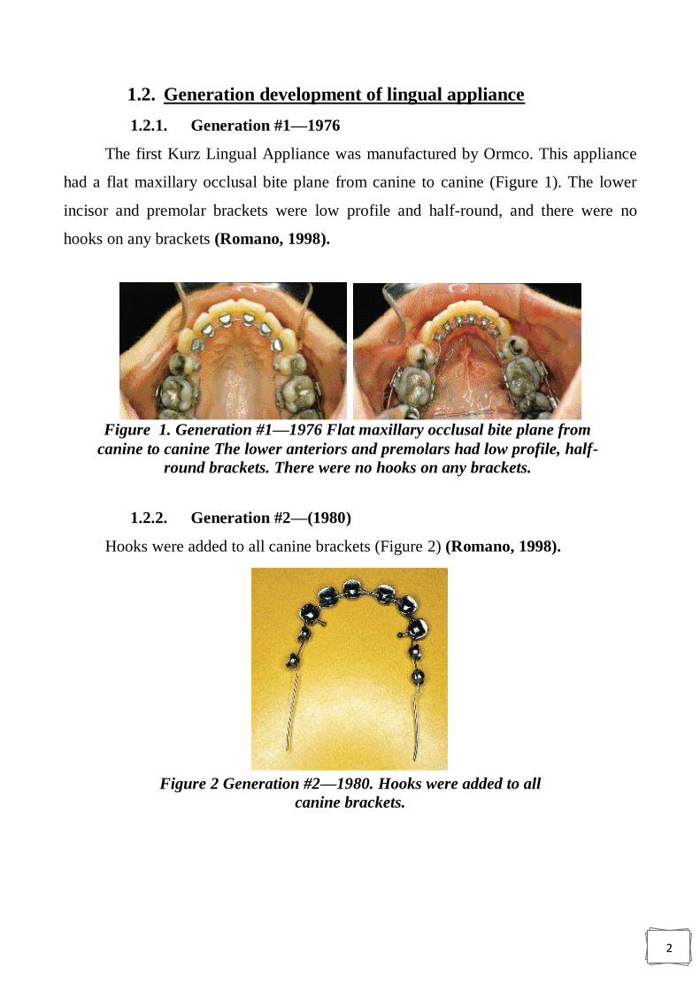
The first Kurz Lingual Appliance was manufactured by Ormco. This appliance
had a flat maxillary occlusal bite plane from canine to canine (Figure 1). The lower
incisor and premolar brackets were low profile and half-round, and there were no
hooks on any brackets (Romano, 1998).
1.2.2. Generation #2—(1980)
Hooks were added to all canine brackets (Figure 2) (Romano, 1998).
Figure 1. Generation #1—1976 Flat maxillary occlusal bite plane from
canine to canine The lower anteriors and premolars had low profile, half-
round brackets. There were no hooks on any brackets.
Figure 2 Generation #2—1980. Hooks were added to all
canine brackets.
3
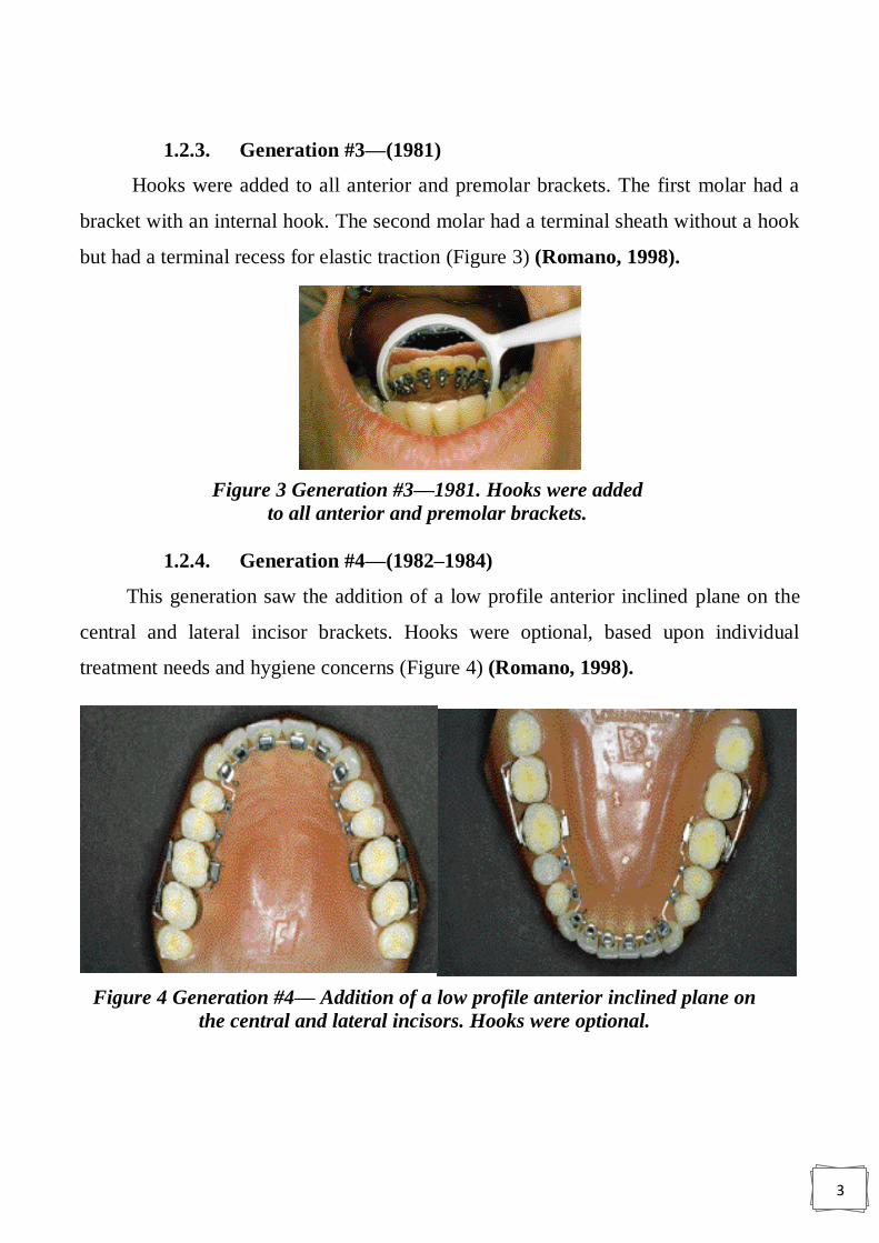
1.2.3. Generation #3—(1981)
Hooks were added to all anterior and premolar brackets. The first molar had a
bracket with an internal hook. The second molar had a terminal sheath without a hook
but had a terminal recess for elastic traction (Figure 3) (Romano, 1998).
1.2.4. Generation #4—(1982–1984)
This generation saw the addition of a low profile anterior inclined plane on the
central and lateral incisor brackets. Hooks were optional, based upon individual
treatment needs and hygiene concerns (Figure 4) (Romano, 1998).
Figure 3 Generation #3—1981. Hooks were added
to all anterior and premolar brackets.
Figure 4 Generation #4— Addition of a low profile anterior inclined plane on
the central and lateral incisors. Hooks were optional.
4
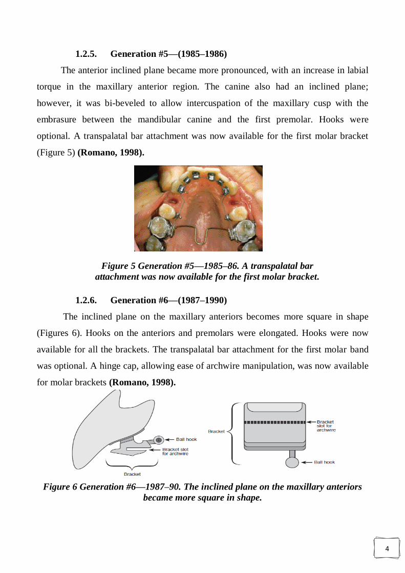
1.2.5. Generation #5—(1985–1986)
The anterior inclined plane became more pronounced, with an increase in labial
torque in the maxillary anterior region. The canine also had an inclined plane;
however, it was bi-beveled to allow intercuspation of the maxillary cusp with the
embrasure between the mandibular canine and the first premolar. Hooks were
optional. A transpalatal bar attachment was now available for the first molar bracket
(Figure 5) (Romano, 1998).
1.2.6. Generation #6—(1987–1990)
The inclined plane on the maxillary anteriors becomes more square in shape
(Figures 6). Hooks on the anteriors and premolars were elongated. Hooks were now
available for all the brackets. The transpalatal bar attachment for the first molar band
was optional. A hinge cap, allowing ease of archwire manipulation, was now available
for molar brackets (Romano, 1998).
Figure 6 Generation #6—1987–90. The inclined plane on the maxillary anteriors
became more square in shape.
Figure 5 Generation #5—1985–86. A transpalatal bar
attachment was now available for the first molar bracket.

5
1.2.7. Generation #7—1990 to present
The maxillary anterior inclined plane is now heart-shaped with short hooks. The
lower anterior brackets have a larger inclined plane with short hooks. All hooks have
greater recess/access for ligation. The premolar brackets were widened mesiodistally
and the hooks were shortened. The increased width of the premolar bracket allows
better angulation and rotation control. The molar brackets now come with either a
hinge cap or a terminal sheath (Figures 7) (Romano, 1998).
Figure 7 Generation #7—1990–present. The maxillary anterior inclined plane is
heart-shaped with short hooks. The lower anterior brackets have a larger inclined
plane with short hooks and all hooks have a greater recess/access for ligation.
1.3. Advantages of lingual orthodontics
A. Aesthetics.
B. No risk to the labial enamel through decalcification.
C. Position of the teeth can be seen more accurately as it is not obscured by the
appliance.
D. Some lingual brackets create a bite-plane effect on the upper incisors and canines,
making these types of brackets useful for treating deep overbites (Michelle, 2013).
E. More beneficial to patients who play musical instruments by mouth, especially
clarinets and saxophones (Grist, 2010).

6
1.4. Disadvantages
A. Patients sometimes have difficulties with speech (Grist, 2010; Papageorgiou et
al, 2016).
B. Masticatory difficulties (Michelle, 2013; Papageorgiou et al, 2016).
C. There can be trauma to edges of the tongue (ulceration) Because of their
position in the mouth, the pliers and hand instruments that are used to fit and
adjust labial appliances would be of little use with lingual appliances. They
need to have very fine edges which allow easy access to the brackets and give a
less restricted view in the mouth. Impression materials are usually rubber based
and models are cast in stone or a hard material (Grist, 2010).
D. More technically demanding for the operator, which increases them Chair-time
and therefore the cost of this approach (Michelle, 2013).
E. Operator proficiency in indirect bonding is required and rebonding failed
brackets can be difficult (Michelle, 2013).
F. More difficult to clean (Michelle, 2013; Ata-Ali et al,2015).
G. Initial alignment can be more challenging in more crowded cases due to reduced
interbracket span (Michelle, 2013).
H. Increased bracket loss (Michelle, 2013).
I. Decreased intermolar width (Papageorgiou et al, 2016)
1.5. Main differences between labial and lingual techniques:
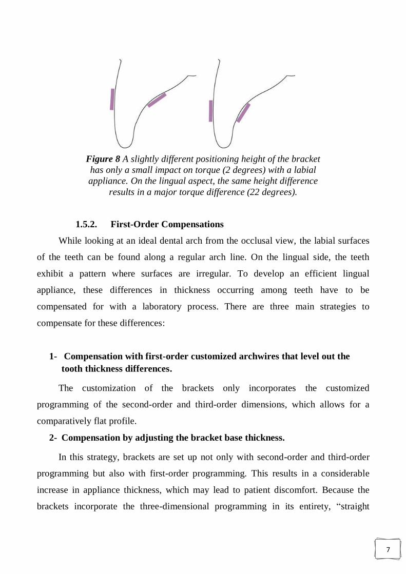
1.5.1. Anatomic Variations of the Lingual Tooth Surfaces
The labial surface of an upper central incisor always follows a similar pattern,
but its lingual surface shows marked morphologic variations among individuals. Even
a small height (vertical) deviation in the position of the brackets results in a marked
effect on the third-order prescription.
7
1.5.2. First-Order Compensations
While looking at an ideal dental arch from the occlusal view, the labial surfaces
of the teeth can be found along a regular arch line. On the lingual side, the teeth
exhibit a pattern where surfaces are irregular. To develop an efficient lingual
appliance, these differences in thickness occurring among teeth have to be
compensated for with a laboratory process. There are three main strategies to
compensate for these differences:
1- Compensation with first-order customized archwires that level out the
tooth thickness differences.
The customization of the brackets only incorporates the customized
programming of the second-order and third-order dimensions, which allows for a
comparatively flat profile.
2- Compensation by adjusting the bracket base thickness.
In this strategy, brackets are set up not only with second-order and third-order
programming but also with first-order programming. This results in a considerable
increase in appliance thickness, which may lead to patient discomfort. Because the
brackets incorporate the three-dimensional programming in its entirety, “straight
Figure 8 A slightly different positioning height of the bracket
has only a small impact on torque (2 degrees) with a labial
appliance. On the lingual aspect, the same height difference
results in a major torque difference (22 degrees).

8
wires” may be used. Although the use of straight wire appliances has been established
in labial techniques, it results in considerable disadvantages in the lingual technique
for both the patient and the orthodontist because of the markedly thicker brackets.
(Graber et al. 2017).
Hohoff et al (2003) reported that thicker appliances cause more patient
discomfort and more problems during speaking and eating. Tongue irritation is also
observed more frequently when brackets encroach on tongue space.
The interbracket distance becomes even shorter because of the increased bracket
thickness. This not only makes inserting the archwires more challenging but also
makes complete bonding of all brackets impossible at the start of treatment, even in
moderate cases of crowding, because of the brackets‟ size. When thicker brackets are
used, the distance between the center of resistance of the tooth and the point of force
application increases, making it more challenging to correct torque problems in the
third dimension. The larger and thicker the bracket, the higher the rate of bracket loss
because there is more chance of biting and debonding a thicker bracket (Graber et al.
2017).
3- Compensation by partial first-order bend of the archwires.
In this case, only the difference in thickness between the canine and the first
premolar is compensated with a first-order bend of the archwire. The archwire is
straight from canine to canine and from first premolar to second molar. The shape of
this archwire setup reminds one of a mushroom, which is why the lingual technique
was also called the “mushroom technique” by its pioneers.
1.5.1. Torque Control
Incorrect torque control results in a completely different effect in a labial bracket
versus a lingual bracket . Two upper central incisors are depicted, one of which
exhibits an ideal position; the other one displays a torque problem of −10 degrees.
When a labial appliance is used, the effect of 10 degrees of torque discrepancy will be
unnoticed by the patient, and only a very detail-oriented orthodontist could recognize
the problem. When a lingual appliance is used, an incorrect torque of −10 degrees

9
directly causes a visible malposition in the vertical plane, and the tooth appears
extruded. This is even more severe as the distance between the tooth surface and the
archwire increases, which is the standard situation when using a lingual straight wire
approach with thicker brackets; vertical discrepancies are easily detected by the patient
(Graber et al., 2017).
Figure 9 A, Different tooth thicknesses are compensated by first-order
archwire bends. B, The archwire is straight. C, Mushroom arch form. D,
Superposition of the three types of archwires.
10
1.5.2. Exposure of Bonding Area
Most orthodontic patients are children and adolescents. Within this age group, the
bonding area of the lingual surface can be reduced, especially in teeth that have just
erupted. This is true, particularly for the upper and lower second molars and the lower
premolars. Bonding conventional lingual appliances is therefore difficult or impossible
in this age group. This is one of the main reasons why in the past, lingual treatment
has been provided only to adults. For this reasons alignment and leveling are different
in lingual orthodontics.
1.5.3. Efficient leveling and aligning with lingual appliances
The leveling and aligning stage presents important differences between common
labial and lingual approaches. Labial appliances allow bonding of all brackets from the
start of treatment in most cases. This is not often the case for lingual systems, where in
the mandibular arch braces have to be bonded in a multistage process depending on
the inserted system. Because of both the repeated performance of bracket bonding
sessions and the more complex task this represents for the preparatory step of gaining
Figure 10 Effect of incorrect torque (−10 degrees) on the vertical position of
the incisor edge of an upper central incisor. A, With a labial appliance, only
0.2 mm of vertical discrepancy an be noticed. B, The same incorrect torque
creates an increased vertical discrepancy (0.7 mm) even if a very flat lingual
appliance is used. C, Thicker lingual appliances (e.g., lingual straight wire
appliances) are not only much more uncomfortable for the patient; they are
also much more prone to third-order problems.
11
space for the respective individual teeth and attachments, this multistage bonding
process is associated with a considerable additional investment in treatment time
(Graber et el, 2017).
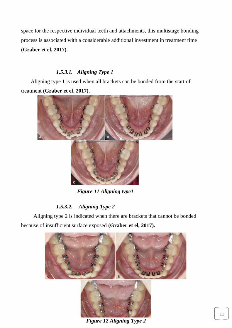
1.5.3.1. Aligning Type 1
Aligning type 1 is used when all brackets can be bonded from the start of
treatment (Graber et el, 2017).
1.5.3.2. Aligning Type 2
Aligning type 2 is indicated when there are brackets that cannot be bonded
because of insufficient surface exposed (Graber et el, 2017).
Figure 11 Aligning type1
Figure 12 Aligning Type 2

12
1.5.3.3. Aligning Type 3
Aligning type 3 is defined by a clinical situation when the dental surface is not
exposed at all, typically when the tooth is impacted or deviated out of arch form
(Graber et el, 2017).
1.6. INDICATIONS and contra indications:
Gupta and Thukral (2015) identified the indications for lingual appliances as
follows:
1. Deep bite cases
2. Class I with mild crowding
3. Class I with generalized spacing
4. Arch expansion
5. Diastema closure
6. Class II with retruded mandible
7. Class I bimaxillary protrusion - all first bicuspid extraction, where in
anchorage is not critical
8. Class II only upper bicuspid extraction
Figure 13 Aligning type 3
13
9. Surgical cases
10. class III cases
While they listed contraindications as follows:
1. Acute Temporo mandibular joint dysfunction
2. Mutilated posterior occlusions
3. High angle / dolichofacial patterns
4. Extensive anterior prosthesis
5. Short clinical crowns
6. Critical anchorage cases
7. Poor oral hygiene or unresolved periodontal involvement
8. Unadaptable or demanding personality types.
1.7. Situations where lingual appliances are more effective
than labial appliances
There are four distinct situations exist where lingual appliances may be more
effective than labial appliances because of their unique mechanical characteristics.
These include:
1. Intrusion of anterior teeth.
2. Maxillary arch expansion.
3. Combining mandibular repositioning therapy with orthodontic movements.
4. Distalization of maxillary molars (Romano. 1998).
1.7.1. Intrusion of Anterior Teeth
The biomechanics of lingual techniques differ considerably from labial
biomechanics. Both arch circumference and inter bracket distance are reduced,
requiring lighter force application for tooth movement.
Lingual bracket position, which is dictated by the morphology of the lingual
surface of the tooth, places the bracket closer to the center of resistance of the tooth
14
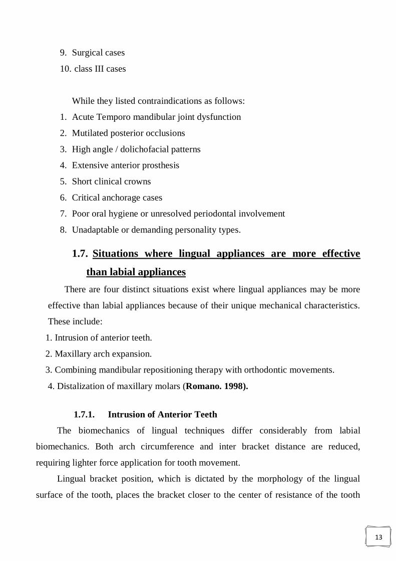
than is found with labial bracket placement (Figure 14).10 An important clinical
implication of this unique bracket position and design is that the intrusive force vector
is directed through the center of resistance of the tooth (Romano, 1998).
As the mandibular anterior dentition occluded with the anterior horizontal plane
of the maxillary anterior brackets, a bite plane effect results. Since the appliance is
bonded, the bite plane is always present. The net effect appears to be a light,
continuous, intrusive force. In addition to these active intrusive forces on the anterior
dentition, a passive extrusion occurs in the posterior segments. Deep-bite correction
Figure 14 . The center of resistance of the tooth is
located closer to the lingual bracket
Figure 15 Occlusal view of the mandibular arch, just after the
partial lingual bonding; the molars were banded afterwards)
15
through this passive increase in posterior vertical dimension and active decrease in
anterior vertical dimension occurs quickly and easily.
Malocclusions requiring open-bite correction obviously would not benefit from
this technique. To prevent the passive extrusion of the posterior segments in these
patients, acrylic posterior overlays are used (Romano, 1998).
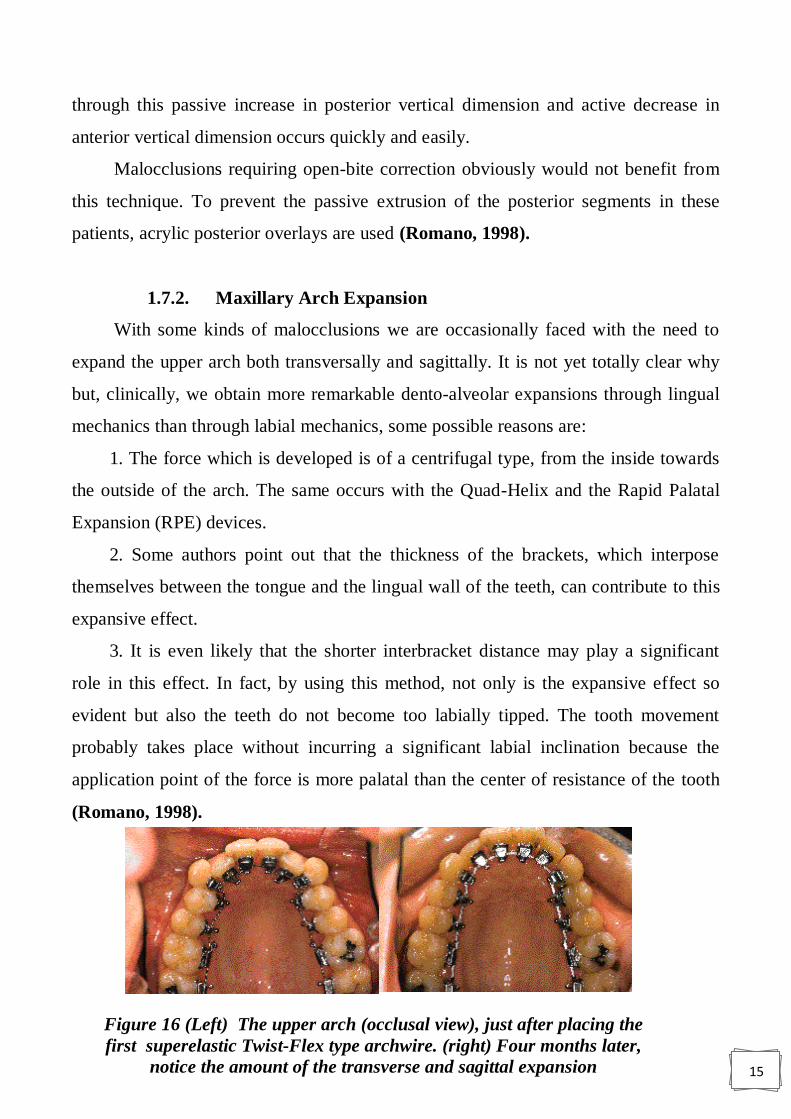
1.7.2. Maxillary Arch Expansion
With some kinds of malocclusions we are occasionally faced with the need to
expand the upper arch both transversally and sagittally. It is not yet totally clear why
but, clinically, we obtain more remarkable dento-alveolar expansions through lingual
mechanics than through labial mechanics, some possible reasons are:
1. The force which is developed is of a centrifugal type, from the inside towards
the outside of the arch. The same occurs with the Quad-Helix and the Rapid Palatal
Expansion (RPE) devices.
2. Some authors point out that the thickness of the brackets, which interpose
themselves between the tongue and the lingual wall of the teeth, can contribute to this
expansive effect.
3. It is even likely that the shorter interbracket distance may play a significant
role in this effect. In fact, by using this method, not only is the expansive effect so
evident but also the teeth do not become too labially tipped. The tooth movement
probably takes place without incurring a significant labial inclination because the
application point of the force is more palatal than the center of resistance of the tooth
(Romano, 1998).
Figure 16 (Left) The upper arch (occlusal view), just after placing the
first superelastic Twist-Flex type archwire. (right) Four months later,
notice the amount of the transverse and sagittal expansion
16
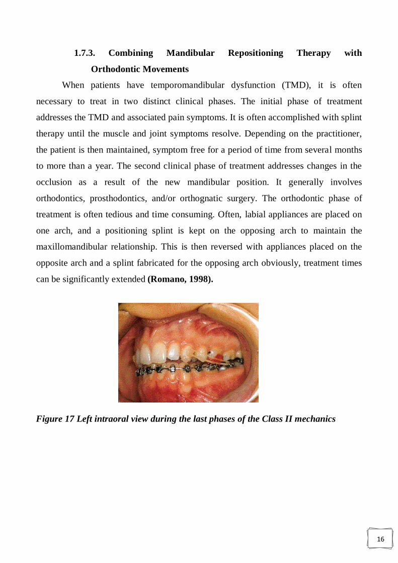
1.7.3. Combining Mandibular Repositioning Therapy with
Orthodontic Movements
When patients have temporomandibular dysfunction (TMD), it is often
necessary to treat in two distinct clinical phases. The initial phase of treatment
addresses the TMD and associated pain symptoms. It is often accomplished with splint
therapy until the muscle and joint symptoms resolve. Depending on the practitioner,
the patient is then maintained, symptom free for a period of time from several months
to more than a year. The second clinical phase of treatment addresses changes in the
occlusion as a result of the new mandibular position. It generally involves
orthodontics, prosthodontics, and/or orthognatic surgery. The orthodontic phase of
treatment is often tedious and time consuming. Often, labial appliances are placed on
one arch, and a positioning splint is kept on the opposing arch to maintain the
maxillomandibular relationship. This is then reversed with appliances placed on the
opposite arch and a splint fabricated for the opposing arch obviously, treatment times
can be significantly extended (Romano, 1998).
Figure 17 Left intraoral view during the last phases of the Class II mechanics
17
1.7.4. Distalization of Maxillary Molars
Lingual brackets are placed closer to the center of rotation (CR) of the tooth
than labial brackets. It is possible that molar distalization through lingual techniques
produce more bodily movement of the tooth and less distal tipping. Because of the
angulation of the multiple roots of maxillary molars, the center of resistance is found
just lingual to the average long axis of the roots (Romano, 1998).
1.8. Problem associated with lingual appliance
The following is a summary listing of some of the difficulties encountered
during the development of lingual orthodontic therapy and the current solutions:
1.8.1. Tissue Irritation and Speech Difficulties
The earlier brackets placed on the lingual surface of the teeth were irritating to
the tongue and impeded normal speech. The current generation of brackets has been
(Figure 18). Initially, anterior brackets had long gingival hooks responsible for
calculus build-up. Lingual orthodontics redesigned with smooth exterior surfaces and
a low profile. The increased comfort allows normal tongue activity, hence speech is
not affected significantly (Romano, 1998).
1.8.2. Gingival Impingement
Earlier generations of the lingual appliance had a broad bonding base extending
towards the gingival margin (Figure 18). Access for adequate oral hygiene and the
self-cleansing nature of the oral cavity were compromised. Brackets have been
redesigned to be more self-cleansing. The base now extends incisally and
mesiodistally, providing adequate bond strength, yet retaining hygienic qualities. The
mandibular anterior teeth are particularly vulnerable to calculus accumulation due to
their close proximity to the submandibular salivary glands. These brackets have 1.5 to
2 mm clearance between the base and the gingival margin. Additionally, the bracket
hooks have been redesigned with a lower profile and are located several millimeters
from the gingival margin (Figures 19) (Romano, 1998).

18
1.8.3. Occlusal Interference
A predominant problem with the original appliance was the effect of the
shearing forces on the brackets, particularly in the maxillary anterior dentition. (In the
absence of a cross-bite, the lingual aspect of the mandibular dentition is generally not
in direct contact with the maxillary dentition; therefore, the shearing forces were not a
problem. Likewise, the relatively high maxillary crown height and low mandibular
cusp height in the posterior segments allow adequate clearance to avoid the severe
shearing forces seen in the maxillary anterior region.) The bracket was redesigned
with an inclined or bite plane strategically placed to redirect the vertical shearing
forces to a horizontal seating force (Figure 19). The location of the inclined plane is
such that when a 1 mm overjet and overbite relationship is obtained; all mandibular
anterior contact with the inclined plane is eliminated. To avoid deleterious effects
caused by tooth contact with the archwire, the inclined plane is located incisal to the
slot. Patient tolerance of the bite plane effect of the inclined plane has been favorable
(Romano, 1998).
Figure 18 Initially, anterior brackets had long gingival hooks responsible for
calculus build-up.
Figure 19 The incline plane. The red arrows represent the primary force
applied, and the broken black lines represent the secondary/resultant forces
exerted

19
1.8.4. Appliance Control
Since the introduction of lingual therapy, control has been a concern. To allow
better control of tooth movements, the appliance was fabricated in high tensile metal
which provides a greater degree of accuracy. First and second molar bands were
manufactured, allowing control from both the buccal and lingual sides of the posterior
segments. An initial treatment approach joined the buccal and lingual attachment
when the wire was engaged. This coupling was thought to prevent vertical and
horizontal rotation of the buccal segments (Figure 20). Clinically, however, this
coupling proved to be unnecessary because one full arch wire from 7-7 was able to
offer much more stability. Currently, transpalatal bars are used for additional stability.
They can be attached to either the first or second molar (Romano. 1998).
1.8.5. Base Pad Adaptation
As with all appliances, accurate contour of base pads improves not only
retentive capabilities but also the accuracy of bracket placement and therefore the
quality of treatment. Topographic maps were constructed for each tooth and individual
bracket base curvatures were calculated (Romano, 1998).
1.8.6. Appliance Placement and Bonding
The original appliances were direct bonded. With the variability of lingual tooth
contours, accurate bracket placement was difficult. This approach produced
unpredictable tooth alignment with tremendous variations in tip, torque, and tooth
height. Initially, the Torque Angulation Referencing Guide (TARG) system was used.
Figure 20 Locking of the molars to the lingual attachment was thought to give
greater appliance control.

20
The TARG instrument was designed to place brackets on the lingual surfaces using
conventional landmarks as references. Although substantial improvements were made
in the accuracy and efficiency of bonding, the system was still inadequate. A more
sophisticated system, using a diagnostic set-up constructed from articulated models
was developed and has met with considerable success.
This method, the Custom Lingual Appliance Set-Up Service (CLASS), involves
indirect bonding set-up on a diagnostic or ideal model of the teeth. The brackets are
then transferred back to the original malocclusion, and transfer trays prepared
(Romano, 1998).
1.8.7. Appliance Prescription
In the early 1970s, Dr. Lawrence Andrews developed and patented a fully
programmed orthodontic appliance, which he introduced as the Straight Wire
Appliance. This philosophy involves programming all the elements necessary to
achieve an optimal occlusion into each bracket.
The initial lingual appliance used a custom-modified labial appliance bonded to
the lingual surface. Tip and torque angulations were not ideal. A similar philosophy
was used to design the Kurz Lingual Appliance. A site was selected on the lingual
surface of each tooth. It was consecutively transferred from the lingual first molar, as
high as it could go, without missing the rounded lingual anatomy.
Reciprocal tip and torque values to Andrew‟s published values were used to
establish the prescription. There was no grand procedure used in obtaining the
reciprocal lingual reference of angles with regard to Andrew‟s published values.
It was a simple matter of mathematically milling a hundred molds to a constant
labial vertical.
The in-out values varied dramatically between the anterior and posterior
segments. To adjust for this with bracket design alone would make the anterior z
brackets thicker than is reasonable, so a true straight wire was not feasible. A first

21
order bend was placed at the junctions of the canine and premolar, and the premolar
and molar. These wires could be prefabricated in the laboratory (Romano, 1998).
1.8.8. Wire Placement
Access for the placement of wires in the molar tubes from the lingual was
limited. Tubes were redesigned by widening the mesial aperture of the slot of the first
molar bracket, creating a funnel effect (Figure 21) (Romano, 1998).
1.8.9. Ligation
To permit stable ligation with ligature wires or elastics, ligature locking grooves
that are both deep set and easy to hook have been designed. When teeth are crowded
and slot engagement is especially difficult, a vertical slot is provided so the archwire
can be attached to the bracket even through the initial stages of leveling and aligning
(Figure 22). A double over-tie with metal is used when a tooth is to be an attachment
for anchorage or rotation of the other teeth (Romano, 1998).
Figure 21 Widening of the mesial aperture to provide ease of wire insertion.
Figure 22 Frontal view of the lingual bracket designed for the maxillary
22
1.8.10. Attachments
A gingival hook is an integral part of the bracket and provides rotational control.
The original hook was large and in close proximity to the gingival margin, impeding
access for hygiene. This hook was redesigned with a lower profile and moved away
from the gingival margin (Romano, 1998).
1.9. Bonding in lingual orthodontic appliance
Among the challenges of lingual orthodontic treatment is the management and
handling of the appliance. This is because the clinician cannot directly see the lingual
surfaces of the teeth and the morphology of the lingual surface of teeth not only varies
among individuals but also presents several features including the cingulum in anterior
teeth, marginal ridges, linguoincisol edge, and lingual grooves. Thus it can be difficult
to place lingual brackets precisely. For these reasons, indirect bonding systems have
become invaluable in lingual orthodontics Lingual orthodontics a new approach using
STB light lingual system & lingual straight wire (Romano, 1998).
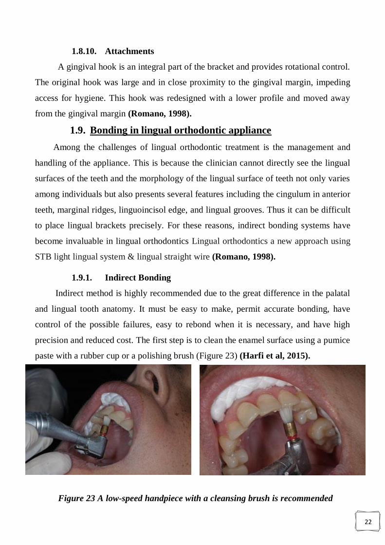
1.9.1. Indirect Bonding
Indirect method is highly recommended due to the great difference in the palatal
and lingual tooth anatomy. It must be easy to make, permit accurate bonding, have
control of the possible failures, easy to rebond when it is necessary, and have high
precision and reduced cost. The first step is to clean the enamel surface using a pumice
paste with a rubber cup or a polishing brush (Figure 23) (Harfi et al, 2015).
Figure 23 A low-speed handpiece with a cleansing brush is recommended
23
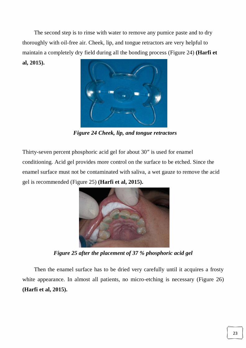
The second step is to rinse with water to remove any pumice paste and to dry
thoroughly with oil-free air. Cheek, lip, and tongue retractors are very helpful to
maintain a completely dry field during all the bonding process (Figure 24) (Harfi et
al, 2015).
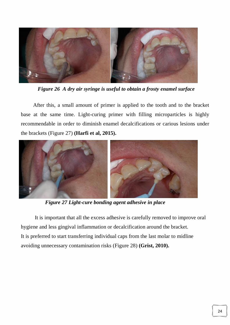
Thirty-seven percent phosphoric acid gel for about 30″ is used for enamel
conditioning. Acid gel provides more control on the surface to be etched. Since the
enamel surface must not be contaminated with saliva, a wet gauze to remove the acid
gel is recommended (Figure 25) (Harfi et al, 2015).
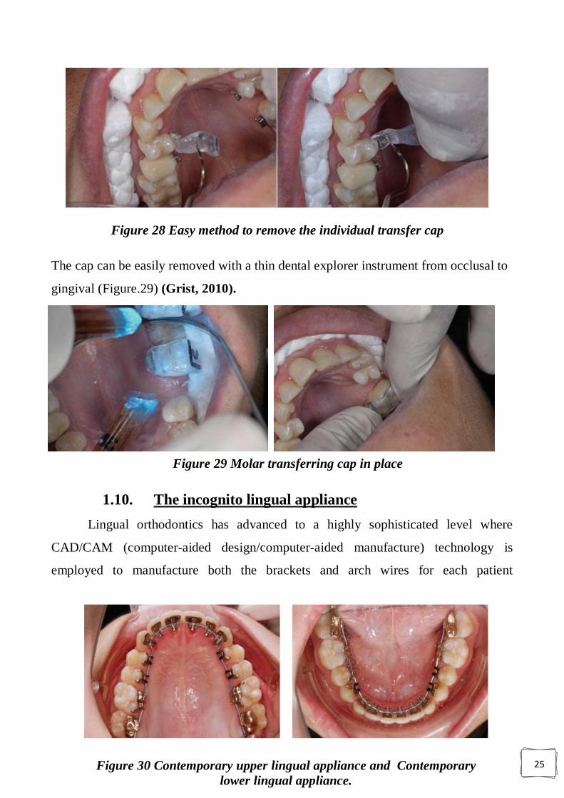
Then the enamel surface has to be dried very carefully until it acquires a frosty
white appearance. In almost all patients, no micro-etching is necessary (Figure 26)
(Harfi et al, 2015).
Figure 24 Cheek, lip, and tongue retractors
Figure 25 after the placement of 37 % phosphoric acid gel
24
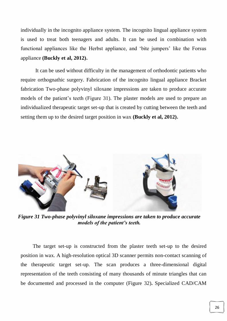
After this, a small amount of primer is applied to the tooth and to the bracket
base at the same time. Light-curing primer with filling microparticles is highly
recommendable in order to diminish enamel decalcifications or carious lesions under
the brackets (Figure 27) (Harfi et al, 2015).
It is important that all the excess adhesive is carefully removed to improve oral
hygiene and less gingival inflammation or decalcification around the bracket.
It is preferred to start transferring individual caps from the last molar to midline
avoiding unnecessary contamination risks (Figure 28) (Grist, 2010).
Figure 26 A dry air syringe is useful to obtain a frosty enamel surface
Figure 27 Light-cure bonding agent adhesive in place
25
The cap can be easily removed with a thin dental explorer instrument from occlusal to
gingival (Figure.29) (Grist, 2010).
1.10. The incognito lingual appliance
Lingual orthodontics has advanced to a highly sophisticated level where
CAD/CAM (computer-aided design/computer-aided manufacture) technology is
employed to manufacture both the brackets and arch wires for each patient
Figure 28 Easy method to remove the individual transfer cap
Figure 29 Molar transferring cap in place
Figure 30 Contemporary upper lingual appliance and Contemporary
lower lingual appliance.
26
individually in the incognito appliance system. The incognito lingual appliance system
is used to treat both teenagers and adults. It can be used in combination with
functional appliances like the Herbst appliance, and „bite jumpers‟ like the Forsus
appliance (Buckly et al, 2012).
It can be used without difficulty in the management of orthodontic patients who
require orthognathic surgery. Fabrication of the incognito lingual appliance Bracket
fabrication Two-phase polyvinyl siloxane impressions are taken to produce accurate
models of the patient‟s teeth (Figure 31). The plaster models are used to prepare an
individualized therapeutic target set-up that is created by cutting between the teeth and
setting them up to the desired target position in wax (Buckly et al, 2012).
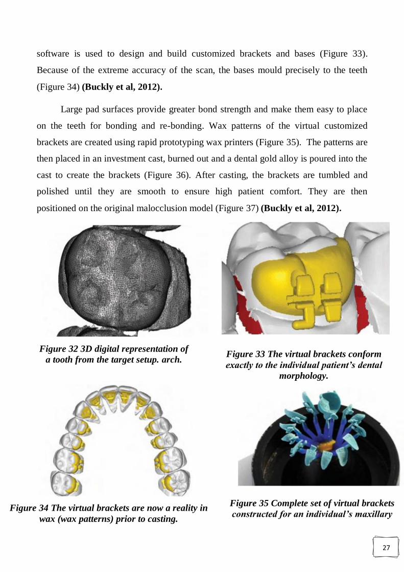
The target set-up is constructed from the plaster teeth set-up to the desired
position in wax. A high-resolution optical 3D scanner permits non-contact scanning of
the therapeutic target set-up. The scan produces a three-dimensional digital
representation of the teeth consisting of many thousands of minute triangles that can
be documented and processed in the computer (Figure 32). Specialized CAD/CAM
Figure 31 Two-phase polyvinyl siloxane impressions are taken to produce accurate
models of the patient’s teeth.
27
software is used to design and build customized brackets and bases (Figure 33).
Because of the extreme accuracy of the scan, the bases mould precisely to the teeth
(Figure 34) (Buckly et al, 2012).
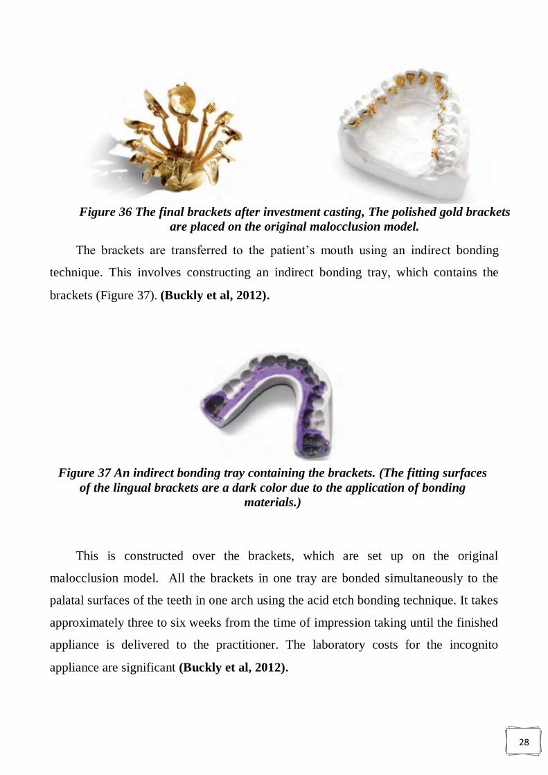
Large pad surfaces provide greater bond strength and make them easy to place
on the teeth for bonding and re-bonding. Wax patterns of the virtual customized
brackets are created using rapid prototyping wax printers (Figure 35). The patterns are
then placed in an investment cast, burned out and a dental gold alloy is poured into the
cast to create the brackets (Figure 36). After casting, the brackets are tumbled and
polished until they are smooth to ensure high patient comfort. They are then
positioned on the original malocclusion model (Figure 37) (Buckly et al, 2012).
Figure 35 Complete set of virtual brackets
constructed for an individual’s maxillary
Figure 32 3D digital representation of
a tooth from the target setup. arch. Figure 33 The virtual brackets conform
exactly to the individual patient’s dental
morphology.
Figure 34 The virtual brackets are now a reality in
wax (wax patterns) prior to casting.
28
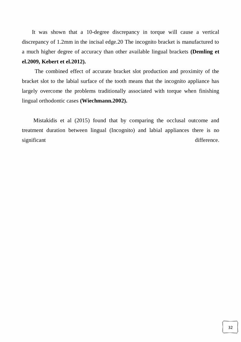
The brackets are transferred to the patient‟s mouth using an indirect bonding
technique. This involves constructing an indirect bonding tray, which contains the
brackets (Figure 37). (Buckly et al, 2012).
This is constructed over the brackets, which are set up on the original
malocclusion model. All the brackets in one tray are bonded simultaneously to the
palatal surfaces of the teeth in one arch using the acid etch bonding technique. It takes
approximately three to six weeks from the time of impression taking until the finished
appliance is delivered to the practitioner. The laboratory costs for the incognito
appliance are significant (Buckly et al, 2012).
Figure 36 The final brackets after investment casting, The polished gold brackets
are placed on the original malocclusion model.
Figure 37 An indirect bonding tray containing the brackets. (The fitting surfaces
of the lingual brackets are a dark color due to the application of bonding
materials.)

29
1.10.1. Problems
According to Buckley et al (2012), the incognito appliance has largely overcome
the three main problems originally associated with the lingual orthodontics technique,
namely:
1. Patient difficulties during the adaptation stage.
2. Difficulties with exact rebonding in the event of bracket loss.
3. Exact finishing.
1.10.1.1. Patient difficulties during the adaptation stage
During the initial adaptation stage, immediately after the appliances are fitted,
patients may experience three main problems speech disturbances, irritation of the
tongue and, masticatory difficulties (Fillion, 1997).
Most patients report a decline in these symptoms in the first two to four weeks of
treatment, though a few are affected for a longer period (Fritz et el, 2002; Hohoff et
el, 2003).
At the initial consultation, it is important to explain to patients about these three
potential problems and to explain that there is an adaptation phase.
In general, in adults only one arch is bonded initially (normally the lower) and
then the other arch is bonded a few weeks later when the patient has had a chance to
adapt. Once patients are aware that there is an adaptation phase this provides
reassurance during the period immediately after the appliances have been fitted.
In general, with teenagers both arches are bonded at the same time, as they adapt
very quickly to the appliances. The incognito lingual bracket system uses custom-
made brackets, which are much thinner than the conventional brackets used in
previous lingual orthodontic appliances (Buckly et al, 2012).
The lower profile of the incognito brackets causes significantly less severe
symptoms during the adaptation phase, and shortens the period of adaptation (Figure
38) (Wiechmann, 2002; Hohoff et el, 2004).

30
1.10.1.2. Difficulties with exact rebonding in the event of bracket
loss
The debond rate of the incognito lingual bracket is very low and comparable to
labial appliances. The extensive individualized base of the incognito lingual bracket,
which covers much of the tooth surface (significantly more than for a labial bracket on
the same tooth), allows each bracket to be directly bonded. This means that a bracket
can be directly rebonded accurately without the additional support of positioning aids
such as small silicone trays. The fact that the base of the bracket is made to precisely
fit the lingual surface of the tooth results in a positive lock when the bracket is pressed
onto the tooth; this greatly facilitates accurate repositioning of the debonded bracket.
In addition, where the teeth have less pronounced morphology, as found in
particular on the lingual surfaces of the lower incisors, accurate rebonding of the
lingual brackets is facilitated by means of „screen shots‟ (Figure 39) from the
manufacturing process, which are routinely supplied with each case (Buckly et al,
2012)
Figure 38 Comparison of a conventional lingual bracket (left) with
incognito bracket (right) shows a pronounced difference in size.
Figure 39 Screenshots of the 3D representation of the positioned brackets
from various angles (as above) serve as an additional rebonding aid.

31
1.10.1.3. Exact finishing
Wiechmann et el (2003) stated that with lingual appliance, finishing and
detailing of the occlusion was a major problem. Three factors originally contributed to
problems in the finishing phase of lingual orthodontic treatment:
1. Inaccurate bracket positioning (Buckly et al, 2012).
2. Inaccurate arch wire fabrication (Rummel et el, 1999).
3. Inaccurate fit between brackets and arch wires (torque play) (Buckly et al, 2012).
Inaccurate bracket positioning
The virtual production of the brackets on the computer almost completely eliminates
errors in the actual production of the bracket bases. By using the extended bases
(positive lock) and the screen shots, positioning the brackets on the individual teeth is
relatively easy, with little room for error. Inaccurate arch wire fabrication all of the
arch wires in the incognito system are produced with CAD/CAM technology; because
of this, inaccurate arch wire fabrication is of minor significance.
This has helped to simplify finishing with lingual orthodontics. Inaccurate fit
between brackets and arch wires (torque play) Torque play in lingual orthodontics
contributed to substantial difficulty in finishing cases in the past.
This is because before the development of the incognito appliance, the arch
wires used tended to be smaller and the slots noticeably larger than the given values
these two factors alone contributed to significant torque play. Incorrect torque will
affect the vertical position of the incisal edges of the teeth (Figure 40) (Buckly et al,
2012).
Figure 40 : Incorrect torque will cause vertical discrepancies in the position of the
incisal edges.
32
It was shown that a 10-degree discrepancy in torque will cause a vertical
discrepancy of 1.2mm in the incisal edge.20 The incognito bracket is manufactured to
a much higher degree of accuracy than other available lingual brackets (Demling et
el.2009, Kebert et el.2012).
The combined effect of accurate bracket slot production and proximity of the
bracket slot to the labial surface of the tooth means that the incognito appliance has
largely overcome the problems traditionally associated with torque when finishing
lingual orthodontic cases (Wiechmann.2002).
Mistakidis et al (2015) found that by comparing the occlusal outcome and
treatment duration between lingual (Incognito) and labial appliances there is no
significant difference.

33
Conclusions
1) Lingual orthodontic appliances are effective in the treatment of malocclusion,
and they represent a good choice for adults where esthetics is a major concern,
especially when cost is not a matter.
2) With the development of customized lingual appliances much of the problems
associated with the previous lingual appliances were overcome.
34
Reference
1. Ata-Ali F, Ata-Ali J, Ferrer-Molina M, Cobo T, De Carlos F, Cobo J.
Adverse effects of lingual and buccal orthodontic techniques: A systematic
review and meta-analysis. Am J Orthod Dentofacial Orthop 2016; 149(6): 820-
829.
2. Buckley, John. Lingual orthodontics. An illustrated review with the incognito
fully customized appliance. Journal of the Irish Dental Association 2012; 58 (3):
149-155
3. Demling A, Dittmer M, Schwestka-Polly R. Comparative analysis of slot
dimension in lingual bracket systems. Head Face Med 2009; 5: 27.
4. Fillion D. Improving patient comfort with lingual brackets. J Clin Orthod 1997;
31: 689-694.
5. Fritz U, Diedrich P, Wiechmann, D. Lingual technique – patients‟
characteristics, motivation and acceptance: Interpretation of a retrospective
survey. J Orofac Orthop 2002; 63: 227-33.
6. Grist F. Basic Guide to Orthodontic Dental Nursing. 1st edition. Blackwell
Publishing Ltd. 2010.
7. Gupta A, Thukral R. Lingual orthodontics – an esthetic
consideration. J Adv Med and Dent Sc Res 2015; 3(5): S54-S56.
8. Harfin J, Ureña A. Achieving Clinical Success in Lingual Orthodontics. New
York: Springer International Publishing, 2015.
9. Hohoff A, Seifert E, Fillion D, Stamm T, Heinecke A et al. Speech
performance in lingual orthodontic patients measured by sonography and
auditive analysis. Am J Orthod Dentofacial Orthop 2003; 123: 146-152.
35
10. Hohoff A, Stamm T, Ehmer U. Comparison of the effect on oral discomfort of
two positioning techniques with lingual brackets. Angle Orthod 2004; 74: 226-
233.
11. Kebert M, mcdonal F, Sherriff M, Cash A. Slot size of lingual orthodontic
brackets: are manufacturing standards being met? Abstract. European Society of
Lingual Orthodontics London UK. 2012: 13.
12. Mistakidis I, Katib H, Vasilakos G, Kloukos D, Gkantidis N. Clinical
outcomes of lingual orthodontic treatment: a systematic review. Eur J
Orthodontics 2016; 38:447-458.
13. Mitchell L. An Introduction to Orthodontics. 4th
Ed., New York: Oxford
University Press, 2013.
14. Papageorgiou SN, G€olz L, J€ager A, Eliades T, Bourauel C. Review
Lingual vs. Labial fixed orthodonticappliances: systematic review and meta-
analysis of treatment effects. European Journal of , 2016 ;124: 105–118.
15. Romano R. Lingual orthodontics. London: B.C .Decker, 1998.
16. Rummel V, Wiechmann D, Sachdeva R. Precision finishing in lingual
orthodontics. J Clin Orthod 1999; 23: 101-113
17. Scuzzo G, Takemoto K. lingual orthodontics A New Approach Using STB
Light Lingual System & Lingual Straight Wire. London, Berlin, Chicago,
Tokyo, Barcelona: quintessence publishing, 2010.
18. Singh G. Textbook of orthodontics (second edition). New delhi: jaypee
brothers medical publishers, 2007.

36
19. Wiechmann D, Rummel V, Thalheim A, Simon J, Wiechmann L.
Customized brackets and archwires for lingual orthodontic treatment. Am J
Orthod Dentofacial Orthop 2003: 124: 593-599.
20. Wiechmann D. A new bracket system for lingual orthodontic treatment. Part 1.
Theoretical background and development. J Orofac Orthop 2002; 63: 234-245.