fabrication of hydrophilic s/in2o3 core–shell nanocomposite for enhancement of photocatalytic...
TRANSCRIPT
Fei
Sa
b
a
ARRAA
KSCBHM
1
eSfCuttteh
Af
h0
Applied Surface Science 324 (2015) 188–197
Contents lists available at ScienceDirect
Applied Surface Science
journa l h om epa ge: www.elsev ier .com/ locate /apsusc
abrication of hydrophilic S/In2O3 core–shell nanocomposite fornhancement of photocatalytic performance under visible lightrradiation
ugang Menga, Zhisheng Caoa, Xianliang Fua, Shifu Chena,b,∗
Department of Chemistry, Huaibei Normal University, Anhui Huaibei, 235000, People’s Republic of ChinaDepartment of Chemistry, Anhui Science and Technology University, Anhui Fengyang, 233100, People’s Republic of China
r t i c l e i n f o
rticle history:eceived 22 September 2014eceived in revised form 18 October 2014ccepted 19 October 2014vailable online 24 October 2014
eywords:/In2O3
ore–shell nanocompositeall-millingeterostructureechanism
a b s t r a c t
Recently, elemental semiconductors as new photocatalysts excited by visible light have attracted greatattention due to their potential applications for environmental remediation and clean energy generation.However, it is still a challenge to fabricate elemental photocatalysts with high activity and stability. In thispaper, a straightforward ball-milling method was carried out to fabricate core–shell S/In2O3 nanocom-posite photocatalyst with high performance. The photocatalyst was characterized by scanning electronmicroscopy (SEM), transmission electron microscopy (TEM), X-ray diffraction (XRD), X-ray photoelec-tron spectroscopy (XPS), UV–vis diffuse reflectance spectroscopy (DRS), Brunauer–Emmett–Teller (BET)method, photoluminescence spectra (PL) and super-hydrophilic experiment. The results showed thatIn2O3 nanoparticles were successfully grown round of S blocks and formed core–shell heterostructures.The 10% S/In2O3 core–shell nanocomposite exhibited the highest photocatalytic activity for degradationof rhodamine B (RhB) under visible light irradiation. The reaction rate constant (k) of the 10% S/In2O3
core–shell nanocomposite is about 8.7 times as high as the sum of pure In2O3 and S because of the forma-tion of core–shell S/In2O3 heterostructures, which might remedy the drawbacks of poor hydrophilicity of
S, enhance visible light absorption and separate the photogenerated carriers efficiently. Furthermore, themechanism of influence on the photocatalytic activity of the S/In2O3 core–shell nanocomposite was alsodiscussed. It is anticipated that our work may open up a new direction for the fabrication of core–shellheterostructure to remedy the drawbacks of a photocatalyst and expand its application in the field of photocatalysis.. Introduction
In recent years, with the development of industry and economy,nvironmental problems have become more and more serious [1].ince Fujishima and Honda reported the evolution of H2 and O2rom a TiO2 electrode under UV-light irradiation in 1972 [2], andarey [3] and Bard [4] found organic pollutants could be degradedsing TiO2 under UV-light irradiation in 1976 and 1977, respec-ively. Semiconductor photocatalysis, as one of the most promisingechnology for environmental remediation and hydrogen produc-
ion, has attracted great attention because it is solar light driven,nvironmental friendly, effective and economical [5–7]. Now itas become a hot spot in many research fields all over the world∗ Corresponding author at: Department of Chemistry, Huaibei Normal University,nhui Huaibei, 235000, People’s Republic of China. Tel.: +86 550 6372001;
ax: +86 550 6732001.E-mail address: [email protected] (S. Chen).
ttp://dx.doi.org/10.1016/j.apsusc.2014.10.104169-4332/© 2014 Elsevier B.V. All rights reserved.
© 2014 Elsevier B.V. All rights reserved.
[8,9]. However, the common photocatalysts (TiO2 [10], ZnO [11],NaNbO3 [12], etc. [13–15]) have such drawbacks as low quan-tum efficiency, rapid recombination of photogenerated carriers andnarrow optical response, which greatly limit their applications inthe treatment of organic pollutants [5–7]. To solve the problem,many semiconductor materials have been exploited as photocata-lysts such as Ag-based semiconductor Ag3PO4 [16], metal-freepolymeric semiconductor g-C3N4 [17], hydroxyl semiconductor[18], graphene–semiconductor composites [19], etc. [20–22]. Thesenovel semiconductors have been proved to be the successful photo-catalysts for degradation of organic pollutants or H2 evolution, andhave expanded the alternative scope of photocatalysts. However,the photocatalytic materials must be improved in order to meetengineering requirements, thus it is of great importance to identifyand design new semiconductor photocatalysts that are abundant,
efficient and stable [7,23].Recently, elemental semiconductors such as B [24], S [25],P [26], Si [27] and Se [28] were introduced as the new metal-free photocatalysts. Among these materials, �-S, being abundant,
ace Sc
saonrprfammwprgsimimS(moohTen
fwscTpBcpmS
2
2
aausCDt
2
swaf
I
I
S. Meng et al. / Applied Surf
table and responsive to visible light, was regarded as one of thelternative semiconductors for splitting water and decomposingrganic molecules under visible light illumination [25,29]. Unfortu-ately, the photocatalytic activity of �-S is too low because of highecombination of photoexcited carriers and poor hydrophilicity. Aossible solution to this problem is to develop methods to reduceecombination of photoexcited carriers and modify the crystal sur-ace of sulfur to be hydrophilic. However, the related researchesbout modifying its surface or improving its photocatalytic perfor-ance have not been reported. Aiming at this project, ball-millingethod was carried out to structure core–shell heterojunction,hich is to erase its hydrophobicity and enhance photocatalyticerformance. At present, the method is widely used for the prepa-ation of nanomaterials and heterostructure owing to its simple andreen process [30–32]. The S-core and hydrophilic semiconductor-hell structure would be able to remedy the hydrophobicity of S andmprove the separation of photogenerated carriers due to the for-
ation of heterostructure. In the paper, Indium trioxide (In2O3), anmportant transparent conducting oxide widely applied in sensor
odules and solar cells [33–36], was selected as shell parts in the-core/semiconductor-shell structure due to its conduction bandCB, about −0.63 eV) and valence band (VB, about 2.17 eV) which
atch well with the CB (about −0.40 eV) and VB (about 2.39 eV)f S [25,35]. Because of the CB of In2O3 is more negative than thatf S, and the VB of S is more positive than that of In2O3, efficienteterostructures could be formed when coupling them together.his will be favorable for the separation of photogenerated carri-rs and improve the photocatalytic efficiency of S/In2O3 core–shellanocomposite dramatically.
In the paper, S-core/In2O3-shell nanocomposite was success-ully prepared by ball-milling of In2O3 mixed with �-S in deionizedater. Various characterizations were performed on the as-
ynthesized samples to get the information of crystal phase,ore–shell structure, surface composition and optical properties.he photocatalytic activity of the S/In2O3 core–shell nanocom-osite was evaluated by photocatalytic degradation of rhodamine
(RhB) under visible light irradiation (� > 420 nm). The S/In2O3ore–shell nanocomposite exhibited remarkable photocatalyticerformance compared with pure S and In2O3. Moreover, theechanism of influence on the photocatalytic activity of the
/In2O3 core–shell photocatalyst was also investigated in detail.
. Experimental
.1. Materials
Indium nitrate (In(NO3)3·5H2O), �-sulfur (S), ammonia solution,nhydrous ethanol, iso-propyl alcohol (IPA), benzoquinone (BQ),mmonium oxalate (AO), rhodamine B (RhB) and other chemicalssed in the experiments are of analytical reagent grade and wereupplied from Sinopharm chemical reagent Co., Ltd. (Shanghai,hina). All of the materials were used without further purification.eionized water used in the synthesis and experiments was from
he local sources.
.2. Preparation of S/In2O3
(a) Synthesis of In2O3 nanoparticles. In2O3 nanoparticles wereynthesized through programmed thermal treatment of In(OH)3,hich was prepared via the precipitation of indium nitrate in
mmonia solution. The compound reactions can be expressed as
ollows:n(NO3)3 + NH4OH → In(OH)3 ↓ +NH4NO3 (1)
n(OH)3 → In2O3 + H2O (2)
ience 324 (2015) 188–197 189
A 12% NH4OH aqueous solution was slowly added into 0.3 MIn(NO3)3 solution under continuous stirring until the final pH of thesolution was up to 8.0. The precipitate was then collected by cen-trifugation, washed with deionized water, and fully dried at 60 ◦Cin an oven to get In(OH)3. In2O3 nanoparticles were obtained byheat treatment of In(OH)3 samples at 360 ◦C for 5 h with a rate of2 ◦C/min.
(b) Fabrication of S/In2O3 core–shell nanocomposite. The S/In2O3photocatalyst was prepared by a simple ball-milling treatmentprocedure. For each sample, 5.0 mL H2O and 1.0 g In2O3 with thedifferent amounts of S were added into an agate tank. The ball-milling was performed at 400 rpm for 3 h. By changing the amountof S powder, the S/In2O3 composites with 0.1, 0.5, 1, 5, 10 and15 wt.% of S were synthesized, labeled by 0.1% S/In2O3, 0.5% S/In2O3,1% S/In2O3, 5% S/In2O3, 10% S/In2O3, 15% S/In2O3, respectively. Forcomparison, �-sulfur S and the synthesized In2O3 were all treatedby the ball-milling method under the same conditions.
2.3. Photoreaction apparatus and procedure
The photocatalytic performance of the samples was evaluatedby degradation of RhB under visible light irradiation. A 500 WXenon lamp (Institute of Electric Light Source, Beijing) with a max-imum emission at about 470 nm was used as visible light source.The lamp was placed in an empty chamber of the annular tube, andrunning water passed through an inner thimble of the annular tubeto cool the system. A 420 nm cutoff filter was placed before the ves-sel to ensure that the reaction system was irradiated only by visiblelight wavelengths. The 0.2 g photocatalyst was added into 100 mLof 1.0 × 10⁻⁵ mol/L RhB solution contained in a 200 mL Pyrex glassvessel.
Prior to illumination, the suspension was magnetically stirredin the dark for 30 min to reach adsorption–desorption equilibrium.After the reaction, 3 mL of reaction solution was sampled at giventime intervals, and centrifuged to remove the photocatalyst. Thecatalyst-free solution was analyzed with a SP-721 spectrophotome-ter (Shanghai Instrument Co., Ltd., China). The concentration ofRhB in solution was determined from its maximum absorption ata wavelength of 554 nm. The photodegradation efficiency of RhBwas calculated from the following expression:
� =[
(C0 − Ct)C0
]× 100% (3)
where � is the photocatalytic degradation efficiency of RhB; C0 isthe initial concentration of RhB; Ct is the concentration of RhB afterillumination time t. In order to determine the reproducibility of theresults, at least triplicate runs were carried out for each conditionfor averaging the results. And the experimental standard error wasfound to be within 0.12%.
In order to test the photocatalytic stability of the samples, theas-prepared photocatalyst was reused five times in the decompo-sition of RhB. After each photocatalytic reaction, the sample wascentrifuged from the reaction solution. The obtained sample waswashed and then dried at 60 ◦C for 3 h. Though the sample was sta-ble and not dissolved in the reaction solution, the loss of the samplewas inevitable in the recycling process. Therefore, the fresh sample(less than 5 wt.%) was added in the next cyclic experiment.
2.4. Characterization of S/In2O3 photocatalysts
X-ray diffraction measurement was carried out at room temper-ature using a BRUKER D8 ADVANCE X-ray powder diffractometer
(XRD) with Cu K� radiation (� = 1.5406 A). The sample’s mor-phology was investigated on JEOL JSM-6610LV scanning electronmicroscope (SEM). X-ray photoelectron spectroscopy (XPS) exam-ination was carried out on a Thermo ESCALAB 250 multifunctional
190 S. Meng et al. / Applied Surface Sc
smtfruart4ls(swlwe6d(aeebtpaacr
3
3
pp2tIridcea
Fig. 1. XRD patterns of In2O3, S and S/In2O3 samples with different contents of S.
pectrometer at 3.0 × 10⁻¹⁰ mbar with Al K� X-ray beam. Trans-ission electron microscopy (TEM) images and high resolution
ransmission electron microscopy (HRTEM) images were per-ormed on a JEOL model JEM 2010 Ex instrument. UV–vis diffuseeflectance spectroscopy (DRS) measurements were carried outsing a Hitachi UV-365 spectrophotometer, and BaSO4 was useds a reflectance standard. Photoluminescence (PL) spectra wereecorded on a JASCO FP-6500 type fluorescence spectrophotome-er with 325 nm excited source over a wavelength range of00–650 nm. Nitrogen adsorption–desorption isotherm was col-
ected at 77 K using OMNISORP100CX equipment. The specificurface area was calculated using the Brunauer–Emmett–TellerBET) method. Fourier transform infrared (FT-IR) spectra of theample before and after the photocatalytic reaction in KBr pelletsere recorded on a Nicolet Avatar 670 FT-IR spectrometer (Nico-
et Corp., USA). The spectra were collected from 4000 to 400 cm−1
ith a 4 cm−1 resolution over 64 scans. The photoelectrochemicalxperiment was measured on an electrochemical station (CHI-60D, China) using a three-electrode system. The samples wereeposited as a film on a 0.5 cm × 0.5 cm fluorine-doped tin oxideFTO) conducting glass to obtain the working electrode. Pt wirend Ag/AgCl were served as the counter electrode and the refer-nce electrode, respectively. 0.2 M Na2SO4 solution was utilized aslectrolyte. The generation of hydroxyl radicals (•OH) was provedy the method of photoluminescence technique with 5 mM tereph-halic acid (PL-TA) and 0.01 M NaOH, and the maximum absorptioneak is 425 nm. Nitroblue tetrazolium (NBT, 2.5 × 10⁻⁵ M, showingn absorption maximum peak at 259 nm, which would be vanisheds NBT captured the generated superoxide radical) was used toheck superoxide radical (•O2
−) generated from the photocatalyticeaction.
. Results and discussion
.1. Characterization of S/In2O3 photocatalysts
Fig. 1 shows the XRD patterns of In2O3, S and S/In2O3 com-osites after ball-milling for 3 h. It can be seen that the crystalhase of In2O3 is cubic with the main diffraction peaks at about� = 20.8◦, 30.1◦, 35.0◦, 50.4◦ and 60.4◦, which could be indexed tohe (2 1 1), (2 2 2), (4 0 0), (4 4 0) and (6 2 2) crystal faces of cubicn2O3, respectively (JCPDS No. 65-3170). The XRD pattern of S cor-esponds to orthorhombic �-S (JCPDS No. 13-0144). Meanwhile, its clear that when the amount of S is lower than 10%, no obvious
iffraction peak of S is found in the S/In2O3 composites. This may beaused by the fact that S is the core in the S/In2O3 composites andxhibits low diffraction. However, with the increase of the loadingmount of S from 10% to 15%, the �-S phase peaks (2� = 23.3◦, 28.3◦ience 324 (2015) 188–197
corresponding to the (1 0 1) and (3 0 0) crystal planes of �-S, respec-tively) are observed and gradually strengthened. Since no newcrystal phases are detected in the S/In2O3 composites, it can beconcluded that a new solid is not formed in the ball-milling pro-cess of S and In2O3. Notably, the diffraction peaks of S and In2O3have no change after ball-milling for 3 h. It is demonstrated that Sand In2O3 keep pure phases in the S/In2O3 composites, and no S isdoped into In2O3 crystal lattice.
SEM was used to investigate the morphology and the effectof In2O3 nanoparticles on the microstructure of the samples.As shown in Fig. 2, spherical In2O3 nanoparticles and irregularS micro-blocks are obtained with the average diameter around10–30 nm and 1–5 �m after ball-milling for 3 h, respectively. WhenIn2O3 nanoparticles are mixed with S micro-blocks for synthe-sis of S/In2O3 composites, the morphology of the as-synthesizedS/In2O3 composites can be chemically tuned, which is quite differ-ent from In2O3 nanoparticles and S micro-blocks. It can be seenfrom Fig. 2c that the characteristic nanoparticle of In2O3 is stillretained, which spreads on the surface of S micro-blocks and formssphere-like core–shell heterostructure. From the hydrophilicitytest, it is notable that S micro-blocks have poor hydrophilicity(the water contact angle, CA = 134.3◦), and that is a vital draw-back of S as a photocatalyst. However, S/In2O3 composites exhibitgood wettability (CA = 9.3◦) because hydrophilic In2O3 nanoparti-cles (CA = 7.3◦) are deposited on the surface of S micro-blocks andformed core–shell heterostructure, which makes it easy to pro-duce good suspensions in aqueous solution and thus increases itsphotocatalytic activity.
To further obtain the core–shell heterostructure information,TEM and energy dispersive spectroscopy (EDS) mapping analysisof S/In2O3 composites have been carried out, as shown in Fig. 3. Itcan be seen from Fig. 3a and b that S/In2O3 composites are coveredwith a large number of In2O3 nanoparticles, which can be provedfrom Fig. 3c and d. The fringes spacing measured at different partsof S/In2O3 nanocomposites are about 0.293 nm and 0.413 nm, cor-responding to the (2 2 2) and (2 1 1) crystal planes of cubic In2O3,respectively. Unfortunately, the fringe spacing possessed S or amor-phous S is not detected. This may be caused by S located at the coreand surrounded by lots of In2O3 nanoparticles.
More importantly, the EDS mapping results (Fig. 3f) further con-firm the composition of an individual heterostructure with a coreof S and a shell of In2O3. In Fig. 3e, the corresponding ringlike pat-tern of selected-area electron diffraction (SAED) indicates that thecomposites have a polycrystalline structure [37]. These results con-firm that the core–shell heterostructure is well-formed betweenS and In2O3 nanoparticles. The rugged In2O3 nanoparticle shellsbring about three merits for the photocatalysis process: modifyingthe crystal surface of sulfur to be hydrophilic; promoting the con-tact of the reactant with the surface of the sample; and formingheterostructure between S and In2O3.
To further investigate the chemical composition and purity ofthe synthesized core–shell S/In2O3 nanocomposite, 10% S/In2O3nanocomposite was further studied by XPS analysis, and the resultsare showed in Fig. 4. The binding energies obtained in the XPS analy-sis are corrected for the C 1s peak at 284.6 eV from the adventitioushydrocarbon contamination. The survey spectra exhibit that theelements such as In, O and S exist in S/In2O3 nanocomposite, and Ccomes from the graphite conductive adhesive. The high-resolutionXPS spectra with scanning over the area corresponding to the bind-ing energies of In, O and S are analyzed in Fig. 4b–d. For In, thepeak located at 451.44 eV corresponds to the In 3d3/2 and anotherone located at 443.89 eV is assigned to In 3d5/2 [37–39]. The split-
ting between 3d3/2 and In 3d5/2 is 7.55 eV, demonstrating a normalstate of In3+ in the S/In2O3 nanocomposite. And the binding energypeaks of O 1s located at 530.81 eV and 529.32 eV are attributed tothe O2− in In2O3 lattice (In–O–In) and the adsorbed oxygen species,
S. Meng et al. / Applied Surface Science 324 (2015) 188–197 191
e on t
r1et4oepsXp
Fig. 2. SEM images and the corresponding photographs of a water droplet shap
espectively [38,39]. What’s more, the S 2p core line fixed at63.9 eV is assigned to the element S, confirming that S remainedlement sulfur after ball-milling with In2O3. It has been reportedhat In 3d signals of In2S3 and metallic In appeared at 445.0 eV,52.5 eV and 443.6 eV, respectively [40,41], and S 2p binding energyf In2S3 is located at 161.3 eV [41]. The absence of these peaksxcludes the existence of metallic In and In2S3, and no obvious
eaks for other impurities are observed. Therefore, the as-preparedample is composed of pure In2O3 and pure S based on the results ofPS measurements. This indicates that the core–shell S/In2O3 com-osite could be easily synthesized by a facile ball-milling approach.Fig. 3. (a and b) TEM images, (c and d) HRTEM images, (e) SAED p
he (a) In2O3, (b) S and (c) 10% S/In2O3 samples (CA is the water contact angle).
Fig. 5 shows the UV–vis diffuse reflectance spectra (DRS) of S,In2O3 and S/In2O3 composites. Compared with the In2O3, the pho-toexcited wavelength ranges of the S/In2O3 composites increasewith the increase of the amount of S. It reveals the good incor-poration between S and In2O3. Moreover, the light absorption ofthe 10% S/In2O3 composite is extended greatly towards the visi-ble light ranges, and the absorption intensity also increases. This
may be favorable for the use of solar light and increases greatly thegeneration rate of photoexcited electron–hole pairs on its surface.Therefore, it can be said that the enhanced light absorption propertyis the precondition for excellent photocatalytic performance.attern and (f) EDS mapping images of 10% S/In2O3 sample.

192 S. Meng et al. / Applied Surface Science 324 (2015) 188–197
pectr
cEpoitaprgw
S
Fw
Fig. 4. XPS spectra of the 10% S/In2O3 composite: (a) survey s
It is known that the optical absorption near the band edge of arystal obeys the equation: ˛hv = A(hv − Eg)n/2, where ˛, h, v, A, andg are absorption coefficient, Planck constant, light frequency, pro-ortionality constant and band gap, respectively; n decides the typef the transition in a semiconductor (n = 1, direct absorption; n = 4,ndirect absorption) [42,43]. In2O3 is an indirect band semiconduc-or, and the value of n is 4 [25]. S is a direct band semiconductor,nd the value of n is 1 [37]. The intercept of the tangent to thelot gives a good approximation of the band gap energy for indi-ect/direct band gap semiconductors. As shown in Fig. S1, the band
aps of In2O3 and S are about 2.80 eV and 2.79 eV, respectively,hich is consistent with the previous reports [25,37].A typical nitrogen adsorption-desorption isotherm of 10%/In2O3 composite is shown in Fig. S2. It is clear that the S/In2O3
200 30 0 40 0 50 0 60 0 70 0 80 0
S 10% S /In 2O3
15% S/ In2O3
5% S/In2O3
1% S/ In2O3
0.5% S/ In2O3
0.1% S/ In2O3
In2O3
Abs
orba
nce
(a.u
.)
Wavelength(nm)
ig. 5. The UV–vis diffuse reflectance spectra of In2O3, S and S/In2O3 compositesith different contents of S.
um and (b–d) high-resolution spectra of In 3d, O 1s and S 2p.
composite exhibits type IV isotherms with type H3 hysteresis loop,implying the sample has porous structure as a result of the accumu-lation of In2O3 nanoparticles and S blocks [44]. The correspondingpore size distribution of the sample is shown in the inset of Fig. S2.The wide pore size distribution may be due to the irregular accu-mulation of In2O3 nanoparticles around S blocks. The BET specificsurface area of the sample is about 5.2 m2 g−1.
3.2. Evaluation of the photocatalytic property
The photocatalytic performance is evaluated by photocatalyticdegradation of RhB under visible light irradiation (� > 420 nm). RhBis selected as a model pollutant, because it is a common con-taminant in industrial wastewater [45]. In order to illustrate thephotocatalytic activity of the photocatalysts, the blank test and thedark absorption test were carried out first. The blank test showsphoto-induced self-sensitized photodegradation has little influ-ence on the results of the experiment. At the same time, the darkabsorption test in the absence of irradiation but with the catalystsshows that no significant change in the substrate concentrationis found. Therefore, the presence of both photocatalyst and illu-mination is necessary for the photocatalytic degradation of RhB.Temporal variations in the concentration of RhB are monitored bydetecting the changes in the maximal absorption in the UV–visspectra at 554 nm. Fig. S3 displays the temporal UV–vis spectralchanges of RhB for the 10% S/In2O3 core–shell photocatalyst. It isclear that the absorption peak of RhB at 554 nm decreases quicklyunder visible light irradiation, and after 80 min of illumination,it reduces almost 90%. Fig. 6 presents the photocatalytic activi-ties of S/In2O3 composites. It is clear that with the increase of Sweight ratio, the photocatalytic activity of the samples increases
greatly up to 10%. When the S weight ratio is higher than 10%, thephotocatalytic activity of the samples gradually decreases. For com-parison, the photocatalytic activities of pure In2O3 and S samplesprepared under identical conditions are also tested and shown in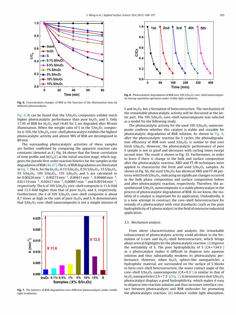
S. Meng et al. / Applied Surface Science 324 (2015) 188–197 193
0 20 40 60 800.0
0.2
0.4
0.6
0.8
1.0
blank In2O3
S 0.1% S/In2O3
0.5% S/ In2O3
1% S/ In2O3
5% S/In2O3
10 % S/ In2O3
15 % S/ In2O3
C/C
0
Time (min)
Fd
Fh1iip8
acogdi5b0raF8t
Fl
4003202401608000.0
0.2
0.4
0.6
0.8
1.0 5th4th3rd2nd
C/C
0
Time (min)
1st
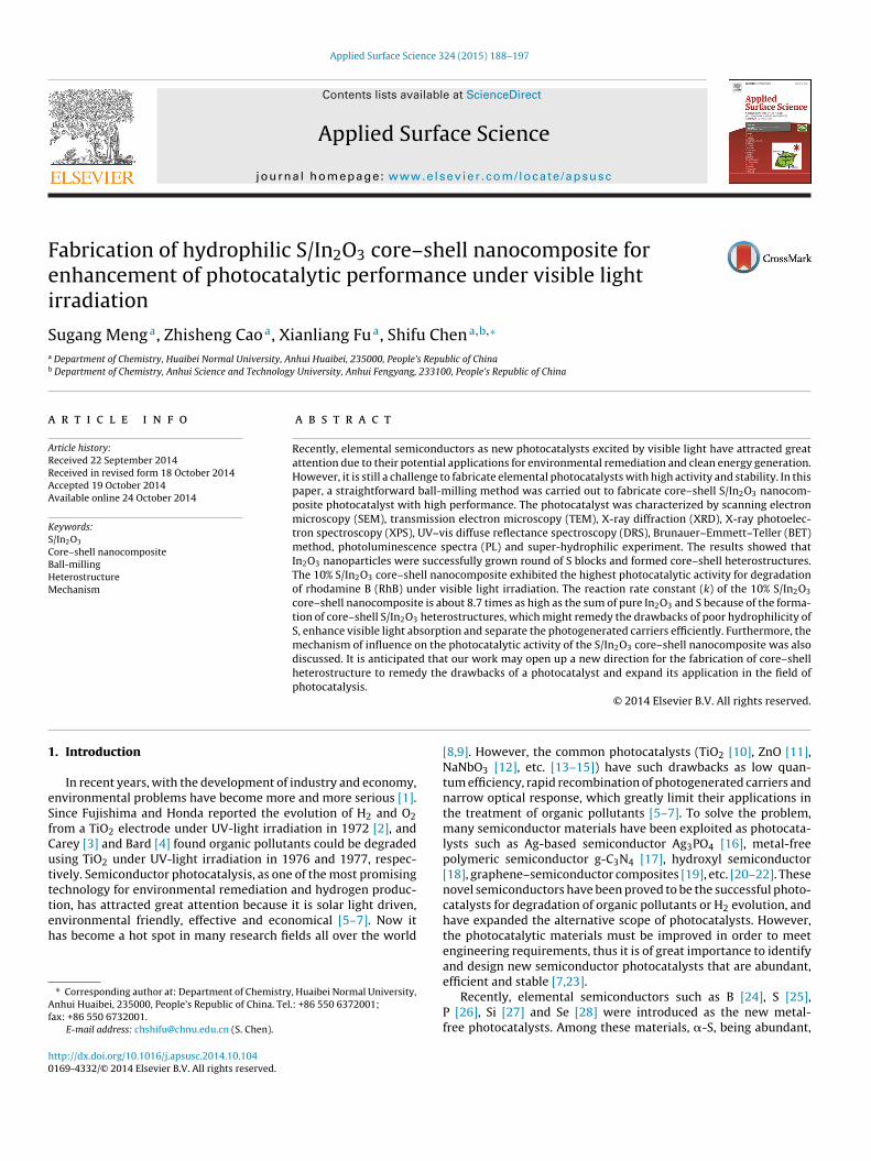
ig. 6. Concentration changes of RhB as the function of the illumination time byifferent photocatalysts.
ig. 6. It can be found that the S/In2O3 composites exhibit muchigher photocatalytic performance than pure In2O3 and S. Only7.9% of RhB for In2O3 and 14.4% for S are degraded after 80 min
llumination. When the weight ratio of S in the S/In2O3 compos-te is 10%, the S/In2O3 core–shell photocatalyst exhibits the highesthotocatalytic activity and almost 90% of RhB are decomposed in0 min.
The outstanding photocatalytic activities of these samplesre further confirmed by comparing the apparent reaction rateonstants (denoted as k). Fig. S4 shows that the linear correlationf time profile and ln(C0/C) at the initial reaction stage, which sug-ests the pseudo first-order reaction kinetics for the samples in theegradation of RhB [46,47]. The ks of RhB degradation are illustrated
n Fig. 7. The ks for the In2O3, 0.1% S/In2O3, 0.5% S/In2O3, 1% S/In2O3,% S/In2O3, 10% S/In2O3, 15% S/In2O3 and S are calculated toe 0.00226 min−1, 0.00273 min−1, 0.00411 min−1, 0.00460 min−1,.01119 min−1, 0.02617 min−1, 0.00807 min−1 and 0.00194 min−1,espectively. The k of 10% S/In2O3 core–shell composite is 11.6-fold
nd 13.5-fold higher than that of pure In2O3 and S, respectively.urthermore, the k of 10% S/In2O3 core–shell composite is about.7 times as high as the sum of pure In2O3 and S. It demonstrateshat S/In2O3 core–shell nanocomposite is not a simple mixture ofS15%10%5%1%0.5%0.1%0.000
0.005
0.010
0.015
0.020
0.025
X 11 .6
k (m
in-1
)
Samples ( X% S/In2O3)
X 13 .5
In2O3
ig. 7. The kinetics of RhB degradation over different photocatalysts under visibleight irradiation.
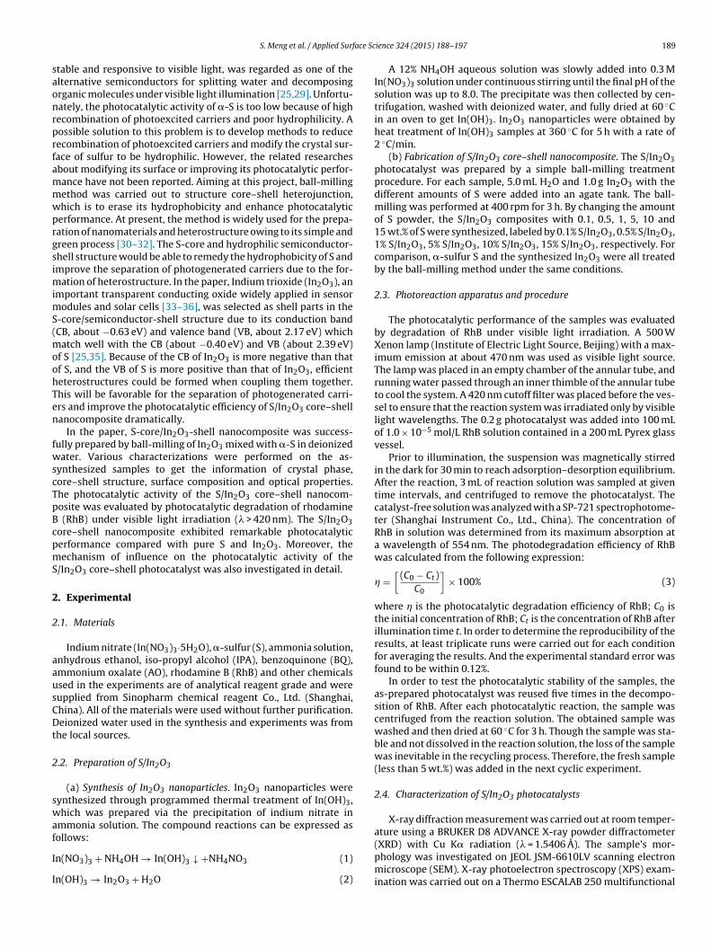
Fig. 8. Photocatalytic degradation of RhB over 10% S/In2O3 core–shell nanocompos-ite during repetition operation under visible light irradiation.
S and In2O3 but a formation of heterostructure. The mechanism ofthe remarkable photocatalytic activity will be discussed at the lat-ter part. The 10% S/In2O3 core–shell nanocomposite was selectedas a model for the following study.
The photocatalytic activity for the used 10% S/In2O3 nanocom-posite confirms whether this catalyst is stable and reusable forphotocatalytic degradation of RhB solution. As shown in Fig. 8,after the photocatalytic reaction for 5 cycles, the photodegrada-tion efficiency of RhB over used S/In2O3 is similar to that overfresh S/In2O3. However, the photocatalytic performance of pureS sample is not so good and decreases with cycling times exceptsecond time. The result is shown in Fig. S5. Furthermore, in orderto learn if there is change in the bulk and surface compositionafter the photocatalytic reaction, XRD and FT-IR techniques wereapplied to characterize the fresh and used S/In2O3 samples. Asshown in Fig. S6, the used S/In2O3 has identical XRD and FT-IR pat-terns with fresh S/In2O3, indicating no significant changes occurredin the bulk phase composition and surface composition beforeand after photocatalytic reaction, respectively. Therefore, the as-synthesized S/In2O3 nanocomposite is a stable photocatalyst in theprocess of photocatalytic degradation of RhB. As we know, the sta-bility of a catalyst is important for its application. Undoubtedly, itis a new attempt to construct the core–shell heterostructure forremedy of a photocatalyst with vital drawbacks (such as the poorhydrophilicity of S photocatalyst) in the field of extensive industrialapplication.
3.3. Mechanism analysis
From above characterization and analysis, the remarkableenhancement of photocatalytic activity could attribute to the for-mation of S-core and In2O3-shell heterostructure, which bringsabout several highlights for the photocatalytic reaction: (i) improvethe wettability of S. The poor hydrophilicity of S (CA = 134.3◦)as a photocatalyst makes it difficult to disperse into aqueoussolution and thus substantially weakens its photocatalytic per-formance. However, when In2O3 sphere-like nanoparticles, ahydrophilic material, are surrounded on the surface of S blocksto form core–shell heterostructure, the water contact angle of thecore–shell S/In2O3 nanocomposite (CA = 9.3◦) is similar to that ofIn2O3 nanoparticles (CA = 7.3◦) (Fig. 1). It demonstrates that S/In2O3
photocatalyst displays a good hydrophilicity, which makes it easyto disperse into reaction solution and thus increases interface con-tact between photocatalysts and RhB molecules for promotingthe photocatalytic reaction; (ii) enhance visible light absorption.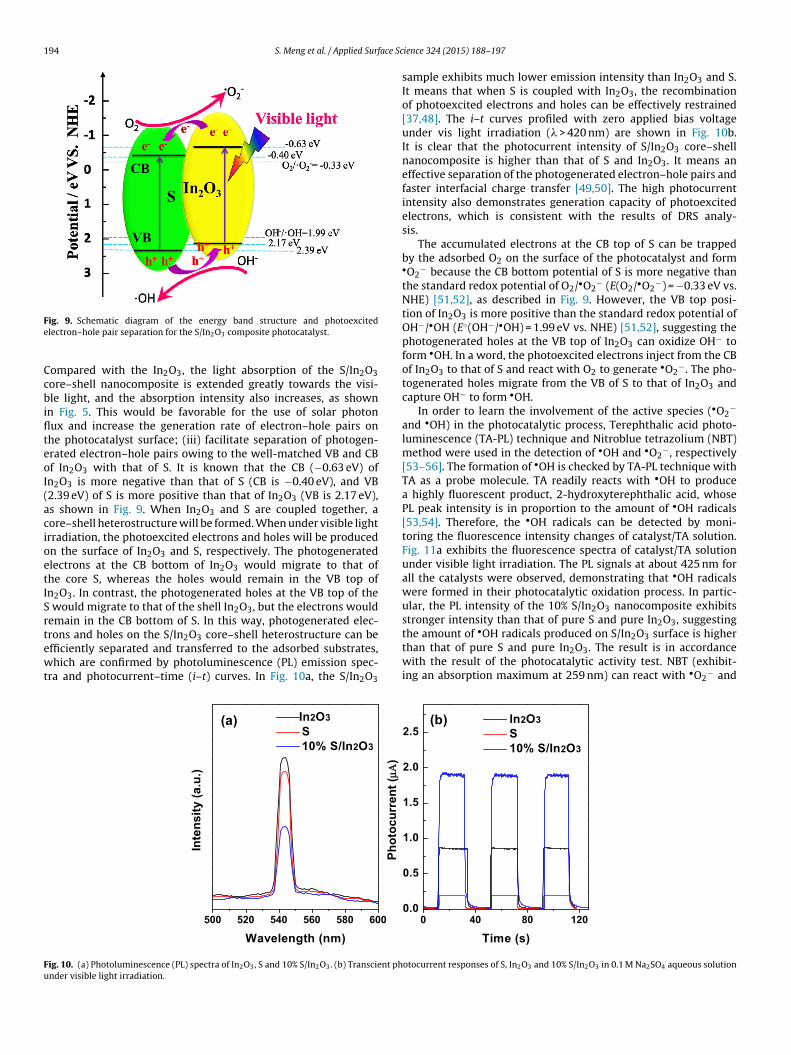
194 S. Meng et al. / Applied Surface Sc
Fe
CcbiflteoI(acioetISrtewt
the amount of •OH radicals produced on S/In O surface is higher
Fu
ig. 9. Schematic diagram of the energy band structure and photoexcitedlectron–hole pair separation for the S/In2O3 composite photocatalyst.
ompared with the In2O3, the light absorption of the S/In2O3ore–shell nanocomposite is extended greatly towards the visi-le light, and the absorption intensity also increases, as shown
n Fig. 5. This would be favorable for the use of solar photonux and increase the generation rate of electron–hole pairs onhe photocatalyst surface; (iii) facilitate separation of photogen-rated electron–hole pairs owing to the well-matched VB and CBf In2O3 with that of S. It is known that the CB (−0.63 eV) ofn2O3 is more negative than that of S (CB is −0.40 eV), and VB2.39 eV) of S is more positive than that of In2O3 (VB is 2.17 eV),s shown in Fig. 9. When In2O3 and S are coupled together, aore–shell heterostructure will be formed. When under visible lightrradiation, the photoexcited electrons and holes will be producedn the surface of In2O3 and S, respectively. The photogeneratedlectrons at the CB bottom of In2O3 would migrate to that ofhe core S, whereas the holes would remain in the VB top ofn2O3. In contrast, the photogenerated holes at the VB top of the
would migrate to that of the shell In2O3, but the electrons wouldemain in the CB bottom of S. In this way, photogenerated elec-rons and holes on the S/In O core–shell heterostructure can be
2 3fficiently separated and transferred to the adsorbed substrates,hich are confirmed by photoluminescence (PL) emission spec-ra and photocurrent–time (i–t) curves. In Fig. 10a, the S/In2O3
600580560540520500
Inte
nsity
(a.u
.)
Wavelength ( nm)
In2O3S10% S/I n2O3
(a)
Phot
ocur
rent
(μμΑΑ
)
ig. 10. (a) Photoluminescence (PL) spectra of In2O3, S and 10% S/In2O3. (b) Transcient phnder visible light irradiation.
ience 324 (2015) 188–197
sample exhibits much lower emission intensity than In2O3 and S.It means that when S is coupled with In2O3, the recombinationof photoexcited electrons and holes can be effectively restrained[37,48]. The i–t curves profiled with zero applied bias voltageunder vis light irradiation (� > 420 nm) are shown in Fig. 10b.It is clear that the photocurrent intensity of S/In2O3 core–shellnanocomposite is higher than that of S and In2O3. It means aneffective separation of the photogenerated electron–hole pairs andfaster interfacial charge transfer [49,50]. The high photocurrentintensity also demonstrates generation capacity of photoexcitedelectrons, which is consistent with the results of DRS analy-sis.
The accumulated electrons at the CB top of S can be trappedby the adsorbed O2 on the surface of the photocatalyst and form•O2
− because the CB bottom potential of S is more negative thanthe standard redox potential of O2/•O2
− (E(O2/•O2−) = −0.33 eV vs.
NHE) [51,52], as described in Fig. 9. However, the VB top posi-tion of In2O3 is more positive than the standard redox potential ofOH−/•OH (E◦(OH−/•OH) = 1.99 eV vs. NHE) [51,52], suggesting thephotogenerated holes at the VB top of In2O3 can oxidize OH− toform •OH. In a word, the photoexcited electrons inject from the CBof In2O3 to that of S and react with O2 to generate •O2
−. The pho-togenerated holes migrate from the VB of S to that of In2O3 andcapture OH− to form •OH.
In order to learn the involvement of the active species (•O2−
and •OH) in the photocatalytic process, Terephthalic acid photo-luminescence (TA-PL) technique and Nitroblue tetrazolium (NBT)method were used in the detection of •OH and •O2
−, respectively[53–56]. The formation of •OH is checked by TA-PL technique withTA as a probe molecule. TA readily reacts with •OH to producea highly fluorescent product, 2-hydroxyterephthalic acid, whosePL peak intensity is in proportion to the amount of •OH radicals[53,54]. Therefore, the •OH radicals can be detected by moni-toring the fluorescence intensity changes of catalyst/TA solution.Fig. 11a exhibits the fluorescence spectra of catalyst/TA solutionunder visible light irradiation. The PL signals at about 425 nm forall the catalysts were observed, demonstrating that •OH radicalswere formed in their photocatalytic oxidation process. In partic-ular, the PL intensity of the 10% S/In2O3 nanocomposite exhibitsstronger intensity than that of pure S and pure In2O3, suggesting
2 3than that of pure S and pure In2O3. The result is in accordancewith the result of the photocatalytic activity test. NBT (exhibit-ing an absorption maximum at 259 nm) can react with •O2
− and
120804000.0
0.5
1.0
1.5
2.0
2.5(b)
Time (s)
In2O3S10% S/In2O3
otocurrent responses of S, In2O3 and 10% S/In2O3 in 0.1 M Na2SO4 aqueous solution

S. Meng et al. / Applied Surface Science 324 (2015) 188–197 195
350 400 450 500 550 200 250 300 350 400 4500.0
0.2
0.4
0.6
0.8
1.0 (b)
Inte
nsity
(a.u
.)
Waveleng th (nm )
10% S/In2O3In2O3STA solution
(a)
Abs
orba
nce
(a.u
.)
Waveleng th (nm )
NBT solutionSIn2O310% S/In2O3
F cts fos prese
tuougatgSo
mtomscw
so
Fefs
ig. 11. (a) The Photoluminescence emission spectral features of the TA–•OH adduolution. (b) The absorbance of nitroblue tetrazolium (NBT) aqueous solution in the
hen its absorption peak would be reduced. So NBT is a widelysed reagent for detection of •O2
− [55,56]. From Fig. 11b, it is obvi-us that the absorbance decreases over all catalyst/NBT solutionnder visible light irradiation, demonstrating that there is •O2
−
enerated from the S/In2O3 photocatalytic system. Specifically, thebsorbance of S/In2O3/NBT solution is the lowest, indicating thathe concentration of NBT in the reaction process was reducedreatly. That is to say, more •O2
− radicals were generated over/In2O3 photocatalytic system. It is in agreement with the resultsf •OH experiment.
The photogenerated electrons and holes are the center of theechanism of the photocatalysis. For photodegradation of dye in
he liquid phase, hole is an important active species, whose strongxidation ability can not only oxidize OH groups to •OH but alsoineralize organic pollutants directly. Electron, another crucial
pecies, can be trapped by molecular oxygen to produce •O2− radi-
als. Therefore, h+, •OH and •O2− are the important active species,
hich directly lead to dye degradation [5].
In order to further understand the roles of these reactivepecies involved in the degradation of RhB in an aqueous phasever S/In2O3 core–shell nanocomposite, the scavenger study was
AOIPABQblank0
20
40
60
80
100
Samples
ηη (%
)
ig. 12. Effects of a series of scavengers (blank, no scavenger added; BQ, scav-nger for superoxide radicals; IPA, scavenger for hydroxyl radicals; AO, scavengeror holes) on the RhB degradation over 10% S/In2O3 photocatalyst (the dosage ofcavengers = 0.1 mmol/L, illumination time t = 80 min).
rmed under visible light irradiation for different samples in terephthalic acid (TA)nce of S, In2O3 and 10% S/In2O3 under visible light irradiation.
performed, which employed different scavengers to remove thecorresponding reactive species, so that the functions of differentreactive species in the photocatalytic process could be understoodbased on the changes of photocatalytic efficiency. The scavengersused in this study were ammonium oxalate (AO, a hole capturer)[57], benzoquinone (BQ, for trapping •O2
−) [58], and isopropanol(IPA, for quenching •OH) [59,60]. From Fig. 12, it can be seen thatthe photodegradation efficiency of RhB over S/In2O3 nanocompos-ite is remarkably decreased when IPA was added into the reactionsystem. The degradation of RhB is also obviously suppressed byadding AO or BQ, but it is not as significant as that with IPA added.The above results indicate that •OH plays a more important rolethan h+ and •O2
− for the degradation of RhB over the core–shellS/In2O3 photocatalyst under visible light irradiation.
4. Conclusions
The core–shell S/In2O3 nanocomposite photocatalyst was suc-cessfully prepared by a facile ball-milling method under mildcondition, and the optimum content of S was found to be 10%.The as-synthesized S/In2O3 nanocomposite is a stable and effi-cient photocatalyst for the photocatalytic degradation of RhB, andthe apparent reaction rate constant of 10% S/In2O3 is 11.6-foldand 13.5-fold higher than that of pure In2O3 and S, respectively.The remarkable enhancement of photocatalytic performance couldattribute to the formation of S-core and In2O3-shell heterostruc-ture, which improves the wettability of S, enhances the visible lightabsorption and facilitates the separation of the photogeneratedelectron–hole pairs owing to the well-matched VB and CB of In2O3with that of S. During the photocatalytic process, •OH plays a moreimportant role than h+ and •O2
−. It is hoped that this work couldrender guided information for remedying drawbacks of a photocat-alyst (such as S photocatalyst which possessed poor hydrophilicity)and steering toward the design and application of such a core–shellnanocomposite with excellent photocatalytic performance.
Acknowledgements
This study was supported by the Natural Science Founda-tion of China (NSFC, grant nos. 51472005, 51172086, 21473066,51272081 and 21103060) and the Natural Science Foundation ofAnhui Province (grant no. 1408085QB38).

1 ace Sc
A
f2
R
[
[
[
[
[
[
[
[
[
[
[
[
[
[
[
[
[
[
[
[
[
[
[
[
[
[
[
[
[
[
[
[
[
[
[
[
[
[
[
96 S. Meng et al. / Applied Surf
ppendix A. Supplementary data
Supplementary data associated with this article can beound, in the online version, at http://dx.doi.org/10.1016/j.apsusc.014.10.104.
eferences
[1] S. Verenich, J. Kallas, Wet oxidation lumped kinetic model for wastewaterorganic burden biodegradability prediction, Environ. Sci. Technol. 36 (2002)3335–3339.
[2] A. Fujishima, K. Honda, Photolysis-decomposition of water at the surface of anirradiated semiconductor, Nature 238 (1972) 37–38.
[3] J.H. Carey, J. Lawrence, H.M. Tosine, Photodechlorination of PCBs in the presenceof titanium dioxide in aqueous suspensions, Bull. Environ. Contam. Toxicol. 16(1976) 697–701.
[4] S.N. Frank, A.J. Bard, Heterogeneous photocatalytic oxidation of cyanide ionin aqueous solutions at titanium dioxide powder, J. Am. Chem. Soc. 99 (1977)303–304.
[5] M.R. Hoffmann, S.T. Martin, W. Choi, D.W. Bahnemann, Environmental appli-cations of semiconductor photocatalysis, Chem. Rev. 95 (1995) 69–96.
[6] X. Chen, S.S. Mao, Titanium dioxide nanomaterials: synthesis, properties, mod-ifications, and applications, Chem. Rev. 107 (2007) 2891–2959.
[7] H. Tong, S.X. Ouyang, Y.P. Bi, N. Umezawa, M. Oshikiri, J.H. Ye, Nano-photocatalytic materials: possibilities and challenges, Adv. Mater. 24 (2012)229–251.
[8] D.M. Schultz, T.P. Yoon, Solar synthesis: prospects in visible light photocata-lysis, Science 343 (2014), 1239176-1–1239176-8.
[9] D.Y.C. Leung, X.L. Fu, C.F. Wang, M. Ni, M.K. Leung, X.X. Wang, X.Z. Fu, Hydro-gen production over titania-based photocatalysts, ChemSusChem 3 (2010)681–694.
10] K.R. Gopidas, M. Bohorquez, P.V. Kamat, Photophysical and photochemicalaspects of coupled semiconductors: charge-transfer processes in colloidal cad-mium sulfide-titania and cadmium sulfide-silver(I) iodide systems, J. Phys.Chem. 94 (1990) 6435–6440.
11] P. Spathis, I. Poulios, The corrosion and photocorrosion of zinc and zinc oxidecoatings, Corros. Sci. 37 (1995) 673–680.
12] K. Katsumata, C.E.J. Cordonier, T. Shichi, A. Fujishima, Photocatalytic activity ofNaNbO3 thin films, J. Am. Chem. Soc. 131 (2009) 3856–3857.
13] C. Burda, Y.B. Lou, X.B. Chen, A.C.S. Samia, J. Stout, J.L. Gole, Enhanced nitrogendoping in TiO2 nanoparticles, Nano Lett. 3 (2003) 1049–1051.
14] W.F. Yao, X.H. Xu, H. Wang, J.T. Zhou, X.N. Yang, Y. Zhang, S.X. Shang, B.B. Huang,Photocatalytic property of perovskite bismuth titanate, Appl. Catal. B: Environ.52 (2004) 109–116.
15] R. Asahi, T. Morikawa, T. Ohwaki, K. Aoki, Y. Taga, Visible-light photocatalysisin nitrogen-doped titanium oxides, Science 293 (2001) 269–271.
16] Z.G. Yi, J.H. Ye, N. Kikugawa, T. Kako, S.X. Ouyang, H. Stuart-Williams, H. Yang,J.Y. Cao, W.J. Luo, Z.S. Li, Y. Liu, R.L. Withers, An orthophosphate semiconductorwith photooxidation properties under visible-light irradiation, Nat. Mater. 9(2010) 559–564.
17] X.C. Wang, K. Maeda, A. Thomas, K. Takanabe, G. Xin, K. Domn, M. Antonietti, Ametal-free polymeric photocatalyst for hydrogen production from water undervisible light, Nat. Mater. 8 (2009) 76–80.
18] (a) X.L. Fu, X.X. Wang, Z.X. Ding, D.Y.C. Leung, Z.Z. Zhang, J.L. Long, W.X. Zhang,Z.H. Li, X.Z. Fu, Hydroxide ZnSn(OH)6: a promising new photocatalyst for ben-zene degradation, Appl. Catal. B: Environ. 91 (2009) 67–72;(b) S.G. Meng, D.Z. Li, M. Sun, W.J. Li, J.X. Wang, J. Chen, X.Z. Fu, G.C. Xiao, Sono-chemical synthesis, characterization and photocatalytic properties of a novelcube-shaped CaSn(OH)6, Catal. Commun. 12 (2011) 972–975.
19] (a) M.Q. Yang, N. Zhang, M. Pagliaro, Y.J. Xu, Artificial photosynthesis overgraphene–semiconductor composites. Are we getting better? Chem. Soc. Rev.(2014), http://dx.doi.org/10.1039/c4cs00213j;(b) N. Zhang, R. Ciriminna, M. Pagliaro, Y.J. Xu, Nanochemistry-derived Bi2WO8nanostructures: towards production of sustainable chemicals and fuels inducedby visible light, Chem. Soc. Rev. 43 (2014) 5276–5287;(c) N. Zhang, Y.H. Zhang, Y.J. Xu, Recent progress on graphene-based photocata-lysts: current status and future perspectives, Nanoscale 4 (2012) 5792–5813;(d) M.Q. Yang, Y.J. Xu, Selective photoredox using graphene-based compositephotocatalysts, Phys. Chem. Chem. Phys. 15 (2013) 19102–19118;(e) Y.H. Zhang, Z.R. Tang, X.Z. Fu, Y.J. Xu, TiO2-graphene nanocomposites forgas-phase photocatalytic degradation of volatile aromatic pollutant: is TiO2-graphene truly different from other TiO2-carbon composite materials? ACSNano 4 (2010) 7303–7314.
20] X. Zong, H.J. Yan, G.P. Wu, G.J. Ma, F.Y. Wen, L. Wang, C. Li, Enhancement ofphotocatalytic H2 evolution on CdS by loading MoS2 as cocatalyst under visiblelight irradiation, J. Am. Chem. Soc. 130 (2008) 7176–7177.
21] S. Dong, Y. Cui, Y. Wang, Y. Li, L. Hu, J. Sun, J. Sun, Designing three-dimensionalacicular sheaf shaped BiVO4/reduced graphene oxide composites for efficient
sunlight-driven photocatalytic degradation of dye wastewater, Chem. Eng. J.249 (2014) 102–110.22] S.G. Meng, D.Z. Li, X.Z. Zheng, J.X. Wang, J. Chen, J.L. Fang, Y. Shao, X.Z. Fu, ZnOphotonic crystals with enhanced photocatalytic activity and photostability, J.Mater. Chem. A 1 (2013) 2744–2747.
[
ience 324 (2015) 188–197
23] Y.Q. Qu, X.F. Duan, Progress, challenge and perspective of heterogeneous photo-catalysts, Chem. Soc. Rev. 42 (2013) 2568–2580.
24] G. Liu, L.C. Yin, P. Niu, J. Wei, H.M. Cheng, Visible-light-responsive �-rhombohedral boron photocatalysts, Angew. Chem. Int. Ed. 52 (2013)6242–6245.
25] G. Liu, P. Niu, L.C. Yin, H.M. Cheng, �-Sulfur crystals as a visible-light-activephotocatalyst, J. Am. Chem. Soc. 134 (2012) 9070–9073.
26] F. Wang, W.K.H. Ng, J.C. Yu, H.J. Zhu, C.H. Li, L. Zhang, Z.F. Liu, Q. Li, Red phos-phorus: an elemental photocatalyst for hydrogen formation from water, Appl.Catal. B: Environ. 111–112 (2012) 409–414.
27] Z.H. Kang, C.H.A. Tsang, N.B. Wong, Z.D. Zhang, S.T. Lee, Silicon quantum dots:a general photocatalyst for reduction, decomposition, and selective oxidationreactions, J. Am. Chem. Soc. 129 (2007) 12090–12091.
28] Y.D. Chiou, Y.J. Hsu, Room-temperature synthesis of single-crystalline Senanorods with remarkable photocatalytic properties, Appl. Catal. B: Environ.105 (2011) 211–219.
29] G. Liu, P. Niu, H.M. Cheng, Visible-light-active elemental photocatalysts,ChemPhysChem 14 (2013) 885–892.
30] (a) S.F. Chen, L. Ji, W.M. Tang, X.L. Fu, Fabrication, characterization andmechanism of a novel Z-scheme photocatalyst NaNbO3/WO3 with enhancedphotocatalytic activity, Dalton Trans. 42 (2013) 10759–10768;(b) N. Zhang, Y.J. Xu, Aggregation- and leaching-resistant, reusable and multi-functional Pd@CeO2 as a robust nanocatalyst achieved by a hollow core–shellstrategy, Chem. Mater. 25 (2013) 1979–1988;(c) N. Zhang, S.Q. Liu, Y.J. Xu, Recent progress on metal core@semiconductorshell nanocomposites as a promising type of photocatalyst, Nanoscale 4 (2012)2227–2238;(d) S.Q. Liu, N. Zhang, Y.J. Xu, Core–shell structured nanocomposites for pho-tocatalytic selective organic transformations, Part. Part. Syst. Char. 31 (2014)540–556.
31] D. Chen, Y. Zhang, Z. Kang, A low temperature synthesis of MnFe2O4 nanocrys-tals by microwave-assisted ball-milling, Chem. Eng. J. 215–216 (2013) 235–239.
32] I.Y. Jeon, H.J. Choi, S.M. Jung, J.M. Seo, M.J. Kim, L. Dai, J.B. Baek, Large-scaleproduction of edge-selectively functionalized graphene nanoplatelets via ballmilling and their use as metal-free electrocatalysts for oxygen reduction reac-tion, J. Am. Chem. Soc. 135 (2013) 1386–1393.
33] G. kolb, S. Keller, D. Tiemann, K.-P. Schelhaas, J. Schürer, O. Wiborg, Design andoperation of a compact microchannel 5 kWel,net methanol steam reformer withnovel Pt/In2O3 catalyst for fuel cell applications, Chem. Eng. J. 207–208 (2012)388–402.
34] X. Li, M.W. Wanlass, T.A. Gessert, K.A. Emery, T.J. Coutts, High-efficiency indiumtin oxide/indium phosphide solar cells, J. Appl. Phys. Lett. 54 (1989) 2674–2676.
35] X. Xiang, L. Xie, Z. Li, F. Li, Ternary MgO/ZnO/In2O3 heterostructured photocata-lysts derived from a layered precursor and visible-light-induced photocatalyticactivity, Chem. Eng. J. 221 (2013) 222–229.
36] L.C. Chen, C.M. Huang, C.S. Gao, G.W. Wang, M.C. Hsiao, A comparative study ofthe effects of In2O3 and SnO2 modification on the photocatalytic activity andcharacteristics of TiO2, Chem. Eng. J. 175 (2011) 49–55.
37] J.B. Mu, B. Chen, M.Y. Zhang, Z.C. Guo, P. Zhang, Z.Y. Zhang, Y.Y. Sun, C.L. Shao,Y.C. Liu, Enhancement of the visible-light photocatalytic activity of In2O3-TiO2
nanofiber heteroarchitectures, ACS Appl. Mater. Interfaces 4 (2012) 424–430.38] C. Donley, D. Dunphy, D. Paine, C. Carter, K. Nebesny, P. Lee, D. Alloway, N.R.
Armstrong, Characterization of indium-tin oxide interfaces using X-ray photo-electron spectroscopy and redox processes of a chemisorbed probe molecule:effect of surface pretreatment conditions, Langmuir 18 (2002) 450–457.
39] T. Maruyama, K. Yorozu, T. Noguchi, Y. Seki, Y. Saito, T. Araki, Y. Nanishi, Sur-face treatment of GaN and InN using (NH4)2Sx , Phys. Status Solidi C 0 (2003)2031–2034.
40] B. Pujilaksono, U. Klement, L. Nyborg, U. Jelvestam, S. Hill, D. Burgard, X-rayphotoelectron spectroscopy studies of indium tin oxide nanocrystalline pow-der, Mater. Charact. 54 (2005) 1–7.
41] S. Rengaraj, S. Venkataraj, C. Tai, Y. Kim, E. Repo, M. Sillanpää, Self-assembled mesoporous hierarchical-like In2S3 hollow microspheres composedof nanofibers and nanosheets and their photocatalytic activity, Langmuir 27(2011) 5534–5541.
42] M.A. Butler, Photoelectrolysis and physical properties of the semiconductingelectrode WO2, J. Appl. Phys. 48 (1977) 1914–1920.
43] J.W. Tang, Z.G. Zou, J.H. Ye, Photophysical and photocatalytic properties ofAgInW2O8, J. Phys. Chem. B 107 (2003) 14265–14269.
44] B. Lee, D. Lu, J.N. Kondo, K. Domen, Three-dimensionally ordered mesoporousniobium oxide, J. Am. Chem. Soc. 124 (2002) 11256–11257.
45] D. Kornbrust, T. Barfknecht, Testing of 24 food, drug, cosmetic, and fabric dyesin the in vitro and the in vivo/in vitro rat hepatocyte primary culture DNA repairassays, Environ. Mutagen. 7 (1985) 101–120.
46] R.W. Matthews, Photocatalytic oxidation and adsorption of methylene blue onthin films of near-ultraviolet-illuminated TiO2, J. Chem. Soc. Faraday Trans. 185 (1989) 1291–1302.
47] S. Pirard, C.M. Malengreaux, D. Toye, B. Heinrichs, How to correctly determinethe kinetics of a photocatalytic degradation reaction? Chem. Eng. J. 249 (2014)1–5.
48] Y.D. Hou, L. Wu, X.C. Wang, Z.X. Ding, Z.H. Li, X.Z. Fu, Photocatalytic performance
of �-, �-, and �-Ga2O3 for the destruction of volatile aromatic pollutants in air,J. Catal. 250 (2007) 12–18.49] H.W. Han, X.Z. Zhao, J. Liu, Enhancement in photoelectric conversion proper-ties of the dye-sensitized nanocrystalline solar cells based on the hybrid TiO2
electrode, J. Electrochem. Soc. 152 (2005) A164–A166.

ace Sc
[
[
[
[
[
[
[
[
[
[
S. Meng et al. / Applied Surf
50] H. Zhang, R.L. Zong, Y.G. Zhu, Photocorrosion inhibition and photoactivityenhancement for zinc oxide via hybridization with monolayer polyaniline, J.Phys. Chem. C 113 (2009) 4605–4611.
51] D.W. Bahnemann, M. Hilgendorff, R. Memming, Charge carrier dynamics atTiO2 particles: reactivity of free and trapped holes, J. Phys. Chem. B 101 (1997)4265–4275.
52] M. Mrowetz, W. Balcerski, A.J. Colussi, M.R. Hoffmann, Oxidative power ofnitrogen-doped TiO2 photocatalysts under visible illumination, J. Phys. Chem.B 108 (2004) 17269–17273.
53] J.C. Barreto, G.S. Smith, N.H.P. Strobel, P.A. McQuillin, T.A. Miller, Terephthalicacid: a dosimeter for the detection of hydroxyl radicals in vitro, Life Sci. 56(1994) 89–96.
54] K. Ishibashi, A. Fujishima, T. Watanabe, K. Hashimato, Quantum yields of active
oxidative species formed on TiO2 photocatalyst, J. Photochem. Photobiol. A 134(2000) 139–142.55] B.H.J. Bielski, H.W. Richter, A study of the superoxide radical chemistry bystopped-flow radiolysis and radiation induced oxygen consumption, J. Am.Chem. Soc. 99 (1977) 3019–3023.
[
ience 324 (2015) 188–197 197
56] L.Q. Ye, J.Y. Liu, Z. Jiang, T.Y. Peng, L. Zan, Facets coupling of BiOBr-gC3N4 composite photocatalyst for enhanced visible-light-drivenphotocatalytic activity, Appl. Catal. B: Environ. 142–143 (2013)1–7.
57] H. Kominami, A. Furusho, S. Murakami, H. Inoue, Y. Kera, B. Ohtani, Effectivephotocatalytic reduction of nitrate to ammonia in an aqueous suspension ofmetal-loaded titanium (IV) oxide particles in the presence of oxalic acid, Catal.Lett. 76 (2001) 31–34.
58] R. Palominos, J. Freer, M.A. Mondaca, H.D. Mansilla, Evidence for hole par-ticipation during the photocatalytic oxidation of the antibiotic flumequine, J.Photochem. Photobiol. A 193 (2008) 139–145.
59] Y. Lin, D. Li, J. Hu, G. Xiao, J. Wang, W. Li, X. Fu, Highly efficient photocatalyticdegradation of organic pollutants by PANI-modified TiO2 composite, J. Phys.
Chem. C 116 (2012) 5764–5772.60] M. Sadakane, K. Sasaki, H. Kunioku, B. Ohtani, W. Ueda, R. Abe, Preparation ofnano-structured crystalline tungsten(VI) oxide and enhanced photocatalyticactivity for decomposition of organic compounds under visible light irradiation,Chem. Commun. 48 (2008) 6552–6554.