exploration, sampling, and in situ soil fileretaining walls, sheet pile bulkheads, ... damage, etc.)...
TRANSCRIPT

1
Exploration, Sampling, and In Situ Soil Measurements

2
Subsurface ExplorationThe purpose of a soil-exploration program is to obtain information on;• Selection of the type and the depth of foundation
fsuitable for a given structure• Evaluation of the load-bearing capacity of the foundation• Estimation of the probable settlement of a structure• Determination of potential foundation problems (for example, expansive soil, collapsible soil, sanitary landfill, and so on)• Establishment of ground water table• Establishment of ground water table• Prediction of lateral earth pressure for structures like retaining walls, sheet pile bulkheads, and braced cuts• Establishment of construction methods for changingsubsoil conditions
3
Purpose of Soil Exploration• Information to determine the type of foundation required
(shallow or deep).• Information to allow the geotechnical engineer to make a• Information to allow the geotechnical engineer to make a
recommendation on the allowable load capacity of the foundation.
• Sufficient data/laboratory tests to make settlement predictions.
• Location of the groundwater table (or determination of whether it is in the construction zone).
Purpose of Soil Exploration Cont’
• Information so that the identification and solution of construction problems (sheeting and dewatering or rockconstruction problems (sheeting and dewatering or rock excavation) can be made.
• Identification of potential problems (settlements, existing damage, etc.) concerning adjacent property.
• Identification of environmental problems and their solution.

4
Planning The Exploration Program
• The subsurface exploration program in l i f th tgeneral comprises of three steps
– Collection of primary data
– Reconnaissance
– Site Investigation
*Locate Utilities

5
Geology Maps
ReconnaissanceThe engineer should always make a visual inspection of the
site to obtain information about
1. The general topography of the site, the possible existence g p g p y , pof drainage ditches, abandoned dumps of debris, and other materials present at the site .
2. Soil stratification from deep cuts, such as those made for the construction of nearby highways and railroads.
3. The type of vegetation at the site, which may indicate the nature of the soilnature of the soil.
4. Groundwater levels, which can be determined by checking nearby wells.

6
5 Th t f t ti b d th i t5. The types of construction nearby and the existence of any cracks in walls or other problems.
6. The nature of the stratification and physical properties of the soil nearby also can be obtained from any available soil- exploration reports on existing structures
Site Investigation
The site investigation phase of the exploration program consists ofp p g
• planning,
• making test boreholes, and
• collecting soil samples at desired intervals for subsequent observation and
• laboratory tests.

7
Types of Investigation
1. Remote sensing
2 G h i l i ti ti2. Geophysical investigations
3. Disturbed sampling
4. In-situ investigation
5. Undisturbed sampling
8
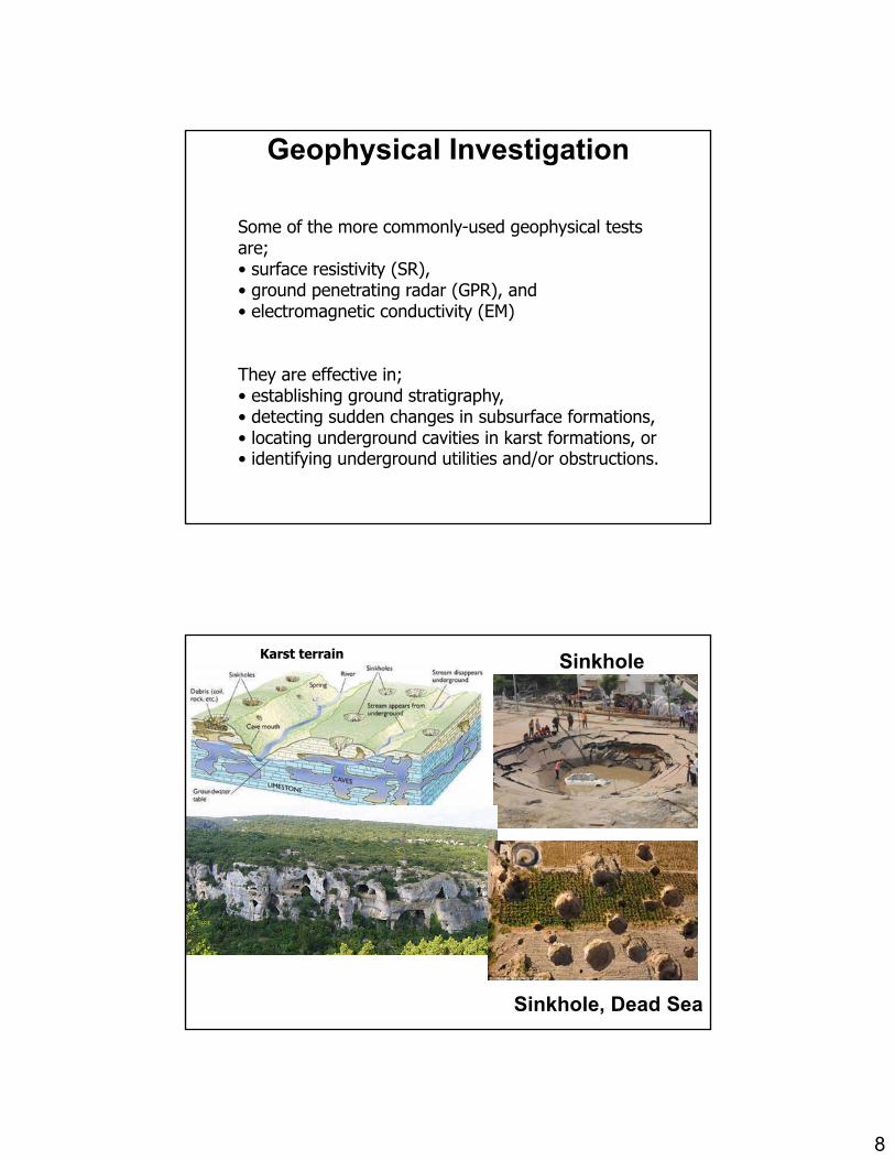
Geophysical Investigation
Some of the more commonly-used geophysical tests are;• surface resistivity (SR),• ground penetrating radar (GPR), and• electromagnetic conductivity (EM)
They are effective in;• establishing ground stratigraphy• establishing ground stratigraphy,• detecting sudden changes in subsurface formations,• locating underground cavities in karst formations, or• identifying underground utilities and/or obstructions.
Karst terrain Sinkhole
Sinkhole, Dead Sea

9
Geophysical Investigation

10
Advantages of Geophysics• Nondestructive and/or non-invasive
Geophysical Investigation
• Nondestructive and/or non-invasive• Fast and economical testing• Applicable to soil and rock
Disadvantages of Geophysics• No sample or direct physical penetration• No sample or direct physical penetration• Models assumed by interpolation• Affected by clay, water, and depth
Types of Investigation
1. Remote sensing
2 G h i l i ti ti2. Geophysical investigations
3. Disturbed sampling
4. In-situ investigation
5. Undisturbed sampling

11
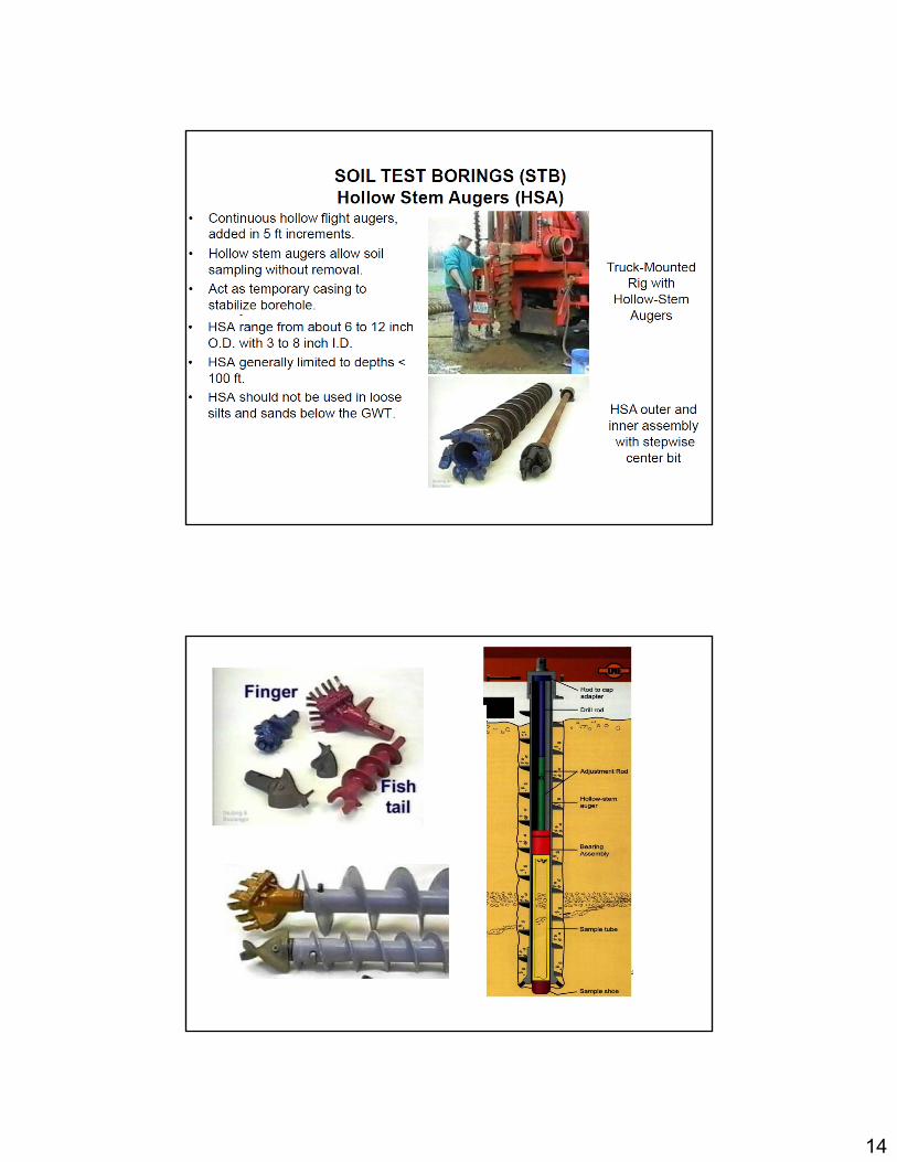
Disturbed sampling
• Disturbed samples are obtained to determine the soil type, gradation, classification, consistency, density, presence of contaminants stratification etcpresence of contaminants, stratification, etc.
• Disturbed samples may be obtained by hand, excavating methods by picks and shovels, or by truck-mounted augers and other rotary drilling techniques.
• These samples are considered “disturbed” since the• These samples are considered disturbed since the sampling process modifies their naturalstructure.
Disturbed sampling

12

13
• track mounted rig
14

15

16
17
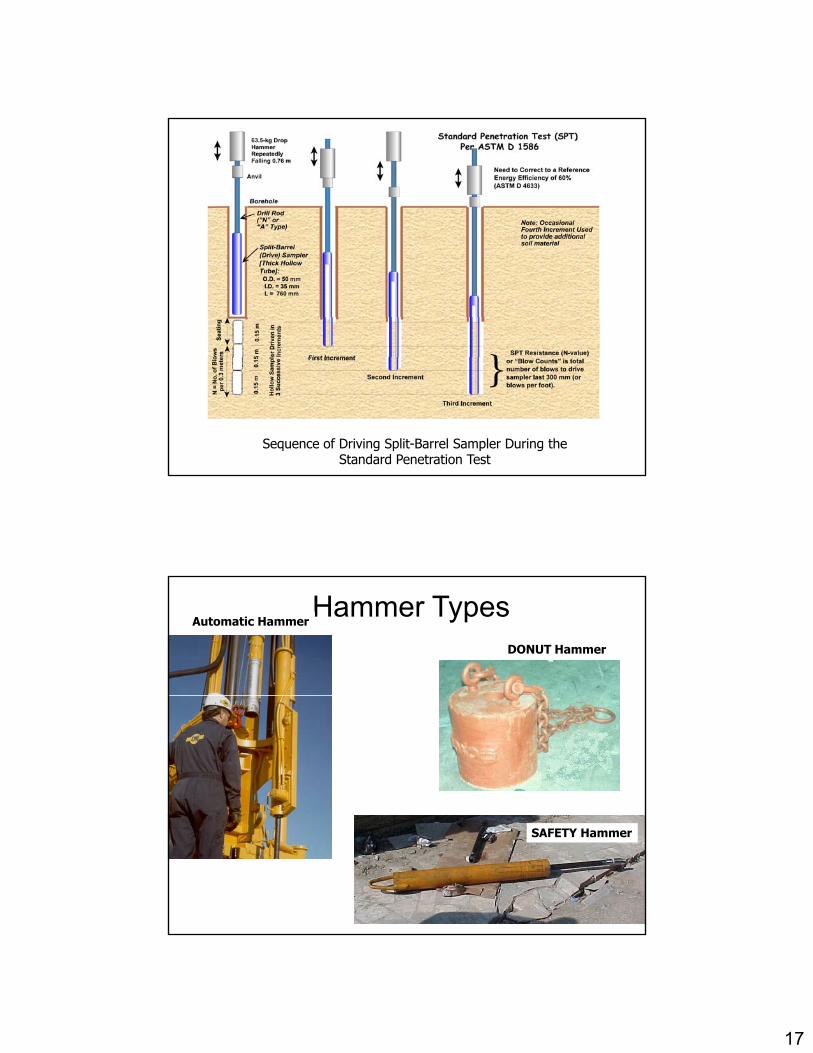
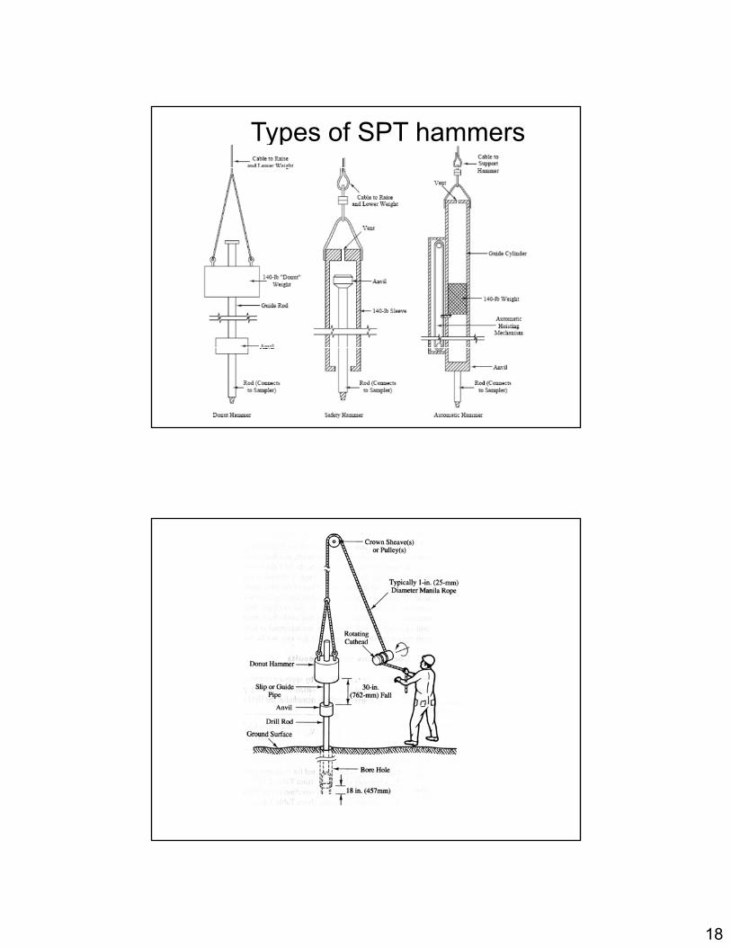
Sequence of Driving Split-Barrel Sampler During the Standard Penetration Test
Hammer TypesDONUT Hammer
Automatic Hammer
SAFETY Hammer
18
Types of SPT hammers

19
STANDARD PENETRATION TEST
• The standard penetration test (SPT) is performed during the advancement of a soil boring to obtain an approximate measure of the dynamic soil resistance, as well as a disturbed drive sample (split barrel type).
• The SPT involves the driving of a hollow thick walled tube into the ground and measuring the number of blows to advance the split-barrel sampler a vertical distance of 300 mm (1 foot).
• A drop weight system is used for the pounding where a 63.5-kg (140-lb) hammer repeatedly falls from 0.76 m (30 inches) to achieve three successive increments of 150-mm (6-inches) each
STANDARD PENETRATION TEST
• The first increment is recorded as a “seating”, while the number of blows to advance the second and third i t d t i th N l ("blincrements are summed to give the N-value ("blow count") or SPT Resistance (reported in blows/0.3 m or blows per foot).
• For partial increments, the depth of penetration is recorded in addition to the number of blows.
• The test can be performed in a wide variety of soil types, as well as weak rocks yet is not particularly useful in theas well as weak rocks, yet is not particularly useful in the characterization of gravel deposits nor soft clays

20
SPT hammer efficiency•• The SPT hammer energy efficiency can be expressed as
• Energy transmitted E= Wh = 63.5 kgf * 76.2 cm = 4838,7 kgf cm= 475 joule 100% efficiency theoretical free fall
• several factors contribute to the variation of the standard penetration number (N) at a given depth for similar soil p ( ) g pprofiles.
1. SPT hammer efficiency,
2. borehole diameter,
3. sampling method, and
4. rod length
•In the field, the magnitude of Er can vary from 30 to 90%. Most correlation were determined using SPT results obtained using the safety hammer. The standard practice now is to express the N-value to anpractice now is to express the N value to anaverage energy ratio of 60% (≈N60) • Thus, correcting for field procedures and on the basis of field observations
21
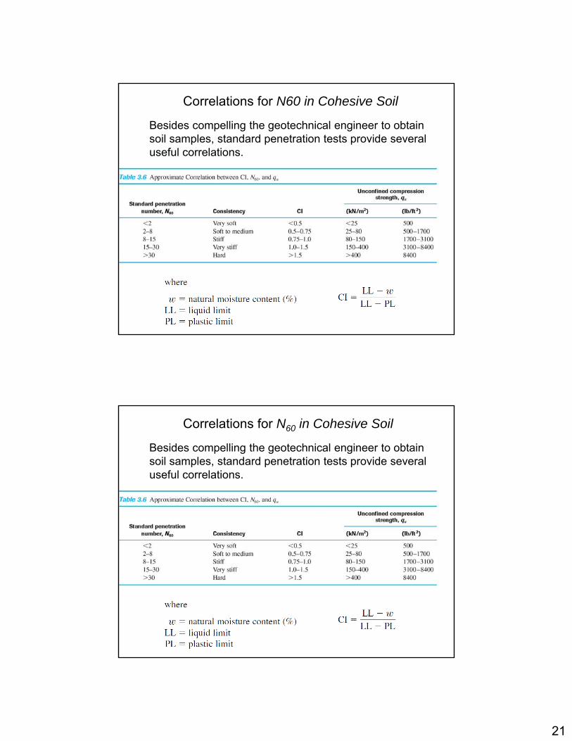
Besides compelling the geotechnical engineer to obtain soil samples, standard penetration tests provide several useful correlations.
Correlations for N60 in Cohesive Soil
Besides compelling the geotechnical engineer to obtain soil samples, standard penetration tests provide several useful correlations.
Correlations for N60 in Cohesive Soil

22
In granular soils, the value of N60 is affected by the effective overburden pressure, vo.
Correction for N60 in Granular Soil
There are different empirical relationships to estimateThere are different empirical relationships to estimate CN
23
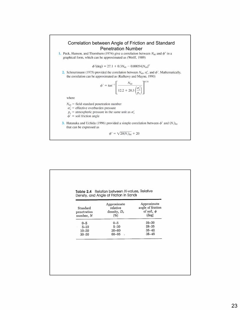
Correlation between Angle of Friction and StandardPenetration Number

24
Correlation between Modulus of Elasticity and Standard Penetration Number
• The modulus of elasticity of granular soils (Es) is an important parameter in estimating the elastic settlementimportant parameter in estimating the elastic settlement of foundations. A first-order estimation for Es was given by Kulhawy and Mayne (1990) as
The following qualifications should be noted when standard penetration resistance values are used in the preceding correlations to estimate soil parameters:
1. The equations are approximate.2 Because the soil is not homogeneous the values of2. Because the soil is not homogeneous, the values of
obtained from a given borehole vary widely.3. In soil deposits that contain large boulders and gravel,standard penetration numbers may be erratic and unreliable.
• Although approximate, with correct interpretation the standard penetration test provides a good evaluation of soilstandard penetration test provides a good evaluation of soil properties.
25
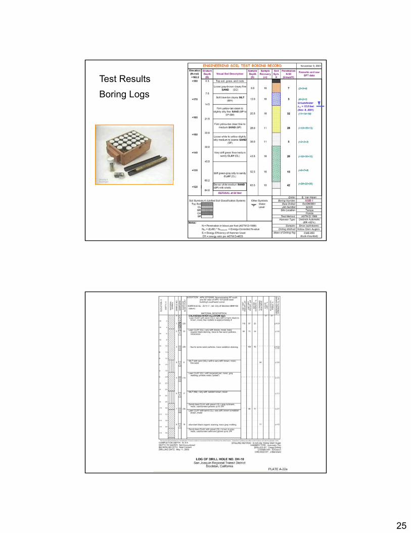
Test Results
Boring Logs

26
Soil Profile
CONE PENETRATION TESTING

27
Cone Penetration Test
Mechanical cone Electric cone

28
CONE PENETRATION TESTING (CPT, PCPT, SCPT)
RESULTS OF A TYPICAL CPT TEST
29
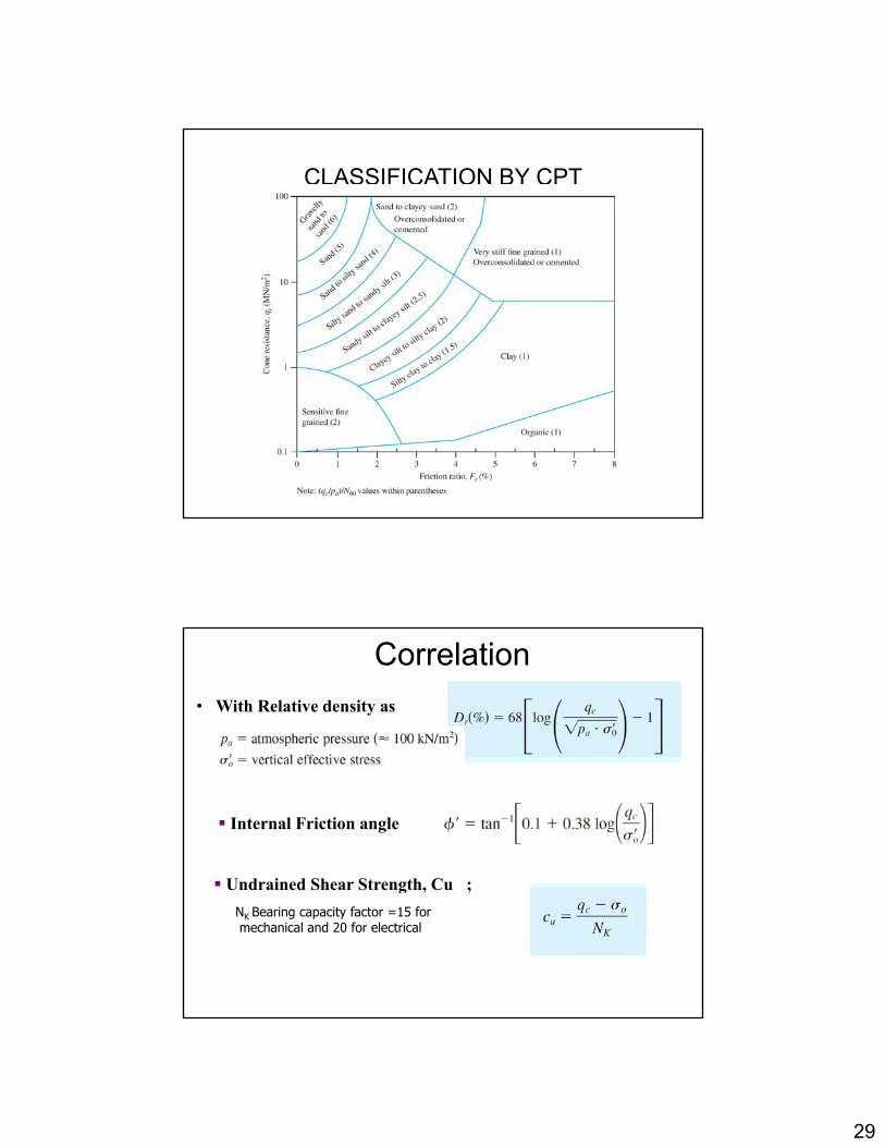
CLASSIFICATION BY CPT
Correlation
• With Relative density as
Internal Friction angle
Undrained Shear Strength, Cu ;Undrained Shear Strength, Cu ;
NK Bearing capacity factor =15 formechanical and 20 for electrical

30
Correlation between qc/N60 and the mean grain size, D50.
FIELD VANE SHEAR TESTING (FVST)
Vane Shear Test

31
Vane Shear Test
• It may be used during the drilling operation to determine the in situ undrained shear strength (Cu ) of clay soils-particularly soft clays.• The vanes of the apparatus are pushed into the soil at the bottom of a borehole without disturbing the soil significantly.• Torque is applied at the top of the rod to rotate the vanes at a standard rate of 0.1 °/sec• This rotation will induce failure in a soil of cylindrical shape surrounding the vanes.
Th i t T li d t f il i• The maximum torque, T, applied to cause failure is measured.

32

33
Sample Disturbance
When the area ratio is 10% or less, the sample generally is considered to be undisturbed.
For a standard split-spoon samplerFor a standard split spoon sampler
Thin Wall Sampler
• The thin-wall tube (Shelby) sampler is commonlyused to obtain relatively undisturbed samples ofcohesive soils for strength and consolidationtestingtesting.• The sampler commonly used has a 76 mmoutside diameter and a 73 mm inside diameter,resulting in an area ratio of 9 percent.• Thin wall samplers vary in outside diameterbetween 51 mm and 76 mm and typically comein lengths from 700 mm to 900 mmin lengths from 700 mm to 900 mm

34
Soil Sampling-source of errors1) The sample is always unloaded from the in situ confining pressures.
2) Sample friction on the sides of the collection device tends to compressthe sample during recovery.
3) There are unknown changes in water content depending on recovery3) There are unknown changes in water content depending on recoverymethod and the presence or absence of water in the ground or borehole.
4) Loss of hydrostatic pressure may cause gas bubble voids to form in thesample.
5) Handling and transporting a sample from the site to the laboratory
6) The quality or attitude of drilling crew, laboratory technicians, and thesupervising engineer may be poor.
7) O h t ld d l d h d t f if t7) On very hot or cold days, samples may dehydrate or freeze if notprotected on-site. Furthermore, worker attitudes may deteriorate intemperature extremes.
ROCK SAMPLING• blow counts are at the refusal level
(N > 100)Use Rock cores
• Coring Bits
The coring bit is the bottommost component of the core barrel assembly.
It is the grinding action of this component that cuts the core from the rock mass.
Three basic categories of bits are; diamond, carbide insert, and sawtooth

35
Rock Drilling and Sampling
36
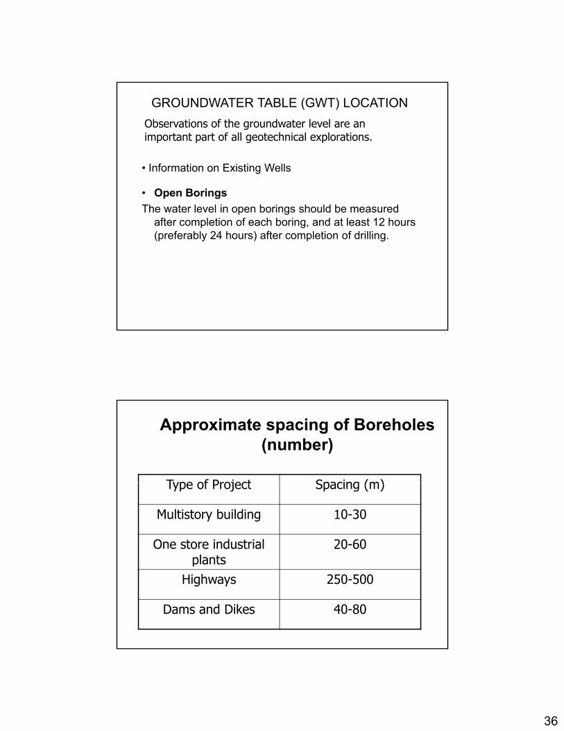
GROUNDWATER TABLE (GWT) LOCATION
Observations of the groundwater level are an important part of all geotechnical explorations.
I f ti E i ti W ll
• Open Borings
The water level in open borings should be measured after completion of each boring, and at least 12 hours (preferably 24 hours) after completion of drilling.
• Information on Existing Wells
Approximate spacing of Boreholes (number)
Type of Project Spacing (m)Type of Project Spacing (m)
Multistory building 10-30
One store industrial plants
20-60p
Highways 250-500
Dams and Dikes 40-80
37
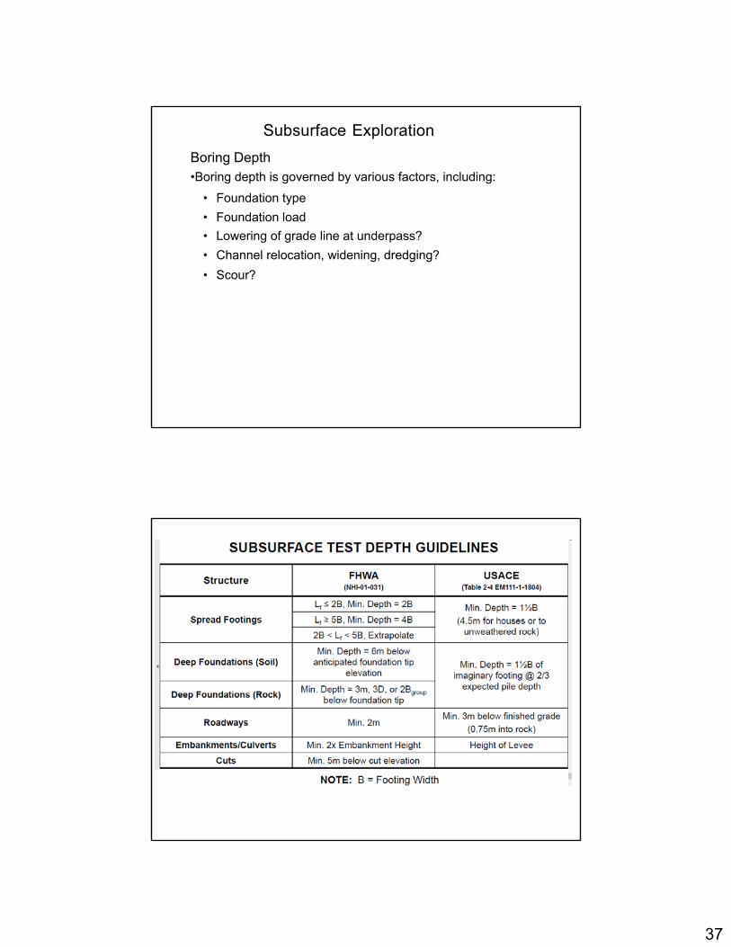
Subsurface Exploration
Boring Depth•Boring depth is governed by various factors, including:
• Foundation type
F d ti l d• Foundation load
• Lowering of grade line at underpass?
• Channel relocation, widening, dredging?
• Scour?

38
Determination of the minimum depth of boring
1.Determine the net increase in the effective stress, ’, under a foundation with depthfoundation with depth.2. Estimate the variation of the vertical effective stress, o’, with depth3.Determine the depth, D1, at which the ’=0.1q ( 10dq (q is estimated net stress on the foundation).
4 D t i th d th D2 t hi h ’/ ’ 0 054. Determine the depth, D2, at which ’/ o’,=0.05.5. Choose the smaller of the two depths, D1 and D2, just determined as the approximate minimum depth of boring required, unless bedrock is encountered.