experimental investigation of flow boiling heat transfer of jet impingement on smooth and micro...
TRANSCRIPT

International Journal of Heat and Mass Transfer 55 (2012) 5093–5101
Contents lists available at SciVerse ScienceDirect
International Journal of Heat and Mass Transfer
journal homepage: www.elsevier .com/locate / i jhmt
Experimental investigation of flow boiling heat transfer of jet impingementon smooth and micro structured surfaces
Sidy Ndao ⇑, Yoav Peles, Michael K. JensenDepartment of Mechanical, Aerospace, and Nuclear Engineering, Rensselaer Polytechnic Institute, Troy, NY 12180, USA
a r t i c l e i n f o
Article history:Available online 14 June 2012
Keywords:Flow boiling heat transferJet impingementMicro pin finsElectronics cooling
0017-9310/$ - see front matter � 2012 Elsevier Ltd. Ahttp://dx.doi.org/10.1016/j.ijheatmasstransfer.2012.05
⇑ Corresponding author. Address: DepartmentMassachusetts Institute of Technology, 77 MassacMA 02139-4307, USA.
E-mail addresses: [email protected] (S. Ndao), pelesyrpi.edu (M.K. Jensen).
a b s t r a c t
Flow boiling heat transfer experiments using R134a were carried out for jet impingement on smooth andenhanced surfaces. The enhanced surfaces were circular micro pin fins, hydrofoil micro pin fins, andsquare micro pin fins. The effects of saturation pressure, heat flux, Reynolds number, pin fin geometry,pin fin array configuration, and surface aging on flow boiling heat transfer characteristics were investi-gated. Flow boiling experiments were carried out for two different saturation pressures, 820 kPa and1090 kPa. Four jet exit velocities ranging from 1.1–4.05 m/s were investigated. Flow boiling jet impinge-ment on smooth surfaces was characterized by large temperature overshoots, exhibiting boiling hyster-esis. Flow boiling jet impingement on micro pin fins displayed large heat transfer coefficients. Heattransfer coefficients as high as 150,000 W/m2 K were observed at a relatively low velocity of 2.2 m/s withthe large (D = 125 lm) circular micro pin fins. Jet velocity, surface aging, and saturation pressure werefound to have significant effects on the two-phase heat transfer characteristics. Subcooled nucleate boil-ing was found to be the dominant heat transfer mechanism.
� 2012 Elsevier Ltd. All rights reserved.
1. Introduction the increase in the heat transfer coefficients with increasing
Single-phase jet impingement heat transfer studies (e.g., [1–5])have shown high heat transfer coefficients compared to parallelflow situations. Further increases in the heat transfer coefficientscan be achieved with flow boiling. Enhancement in the heat trans-fer coefficients for flow boiling jet impingement is generally attrib-uted to the associated latent heat of vaporization and flow mixinginduced by the violent departure on bubbles from the heated sur-face. Studies of submerged jet impingement have suggested twotypes of boiling regimes [6], namely nucleate boiling and convec-tive boiling. An extensive survey of the literature of phase-changejet impingement can be found in Cohen et al. [6]; hence, we willlimit this review to only a few papers relevant to the current study.
Ma and Bergles [7] experimentally investigated characteristicsof nucleate boiling with jet impingement using R113 with varyingvelocity, subcooling, flow direction and surface condition. Two jetdiameters, 1.07 mm and 1.81 mm, and two heaters, 5 � 5 mmand 3 � 3 mm, were used in the experiments. The effects of jetvelocity were manifested by a decrease in temperature overshootwith increasing jet velocity. This observation was attributed to
ll rights reserved..009
of Chemical Engineering,husetts Avenue, Cambridge,
@rpi.edu (Y. Peles), JenseM@
velocities. Surface condition was also found to have significant ef-fects on the fully developed boiling regime with the boiling curvessignificantly shifting as a result of surface aging.
Mudawar and Wadsworth [8] investigated the CHF condition ofboiling heat transfer from a smooth heat source using a rectangularnozzle jet of dielectric Fluorinert FC-72. The heater had dimensionsof 12.7 � 12.7 mm, nozzle width and jet-to-surface height werevaried from 0.127–0.508 mm and 0.508–5.08 mm, respectively.The inlet subcooling was varied from 0 to 40 �C. For mediumvelocities, stand-off ratios had little effect on the CHF. For relativelyhigh velocities, decreasing the stand-off ratio increased the CHF. Anempirical correlation was developed for the medium velocityregime.
Wolf et al. [9] studied local jet impingement boiling heat trans-fer to reveal the fundamental issues that influence boiling heattransfer to a free-surface planar jet of water. They concluded thatthe heat transfer mechanisms within the fully-developed boilingregime were insensitive to jet velocity but, rather, were dominatedby evaporation and intense mixing due to bubbles departure. How-ever, in the single-phase and partial boiling regimes, jet velocityhad significant effects on the heat transfer coefficients due to theconvective nature of the heat transfer mechanism in those regimes.Streamwise distance from the stagnation point showed some ef-fects on the single-phase heat transfer coefficients, while thatwas not the case for the fully-developed regime. Based on theexperimental data and their interpretation, a correlation for thefully-developed boiling region was developed and given by:

Nomenclature
A area (m2)d diameter (m)D pin fin diameter (m)h average heat transfer coefficient (W/m2 K)I current (A)k thermal conductivity (W/m K)Q heat input (W)q00 heat flux (W/cm2)Red Reynolds number based on diameter (d)t thickness (m)T temperature (K)V velocity (m/s)VT voltage (V)
Greek symbolsl viscosity (kg/m s)
q density (kg/m3)
Subscriptsconv convectivef fluidh heateri inletj jetl liquids solidsat saturationsub subcooledw wall
5094 S. Ndao et al. / International Journal of Heat and Mass Transfer 55 (2012) 5093–5101
q00 ¼ 63:7DT2:95sat ð1Þ
where DTsat is the wall superheat. As can be seen from the correla-tion, the heat flux is independent of velocity and can only be usedfor water.
Zhou et al. [10] experimentally studied the boiling hysteresischaracteristics of impinging circular submerged jets with highlywetting liquids. The effects of jet exit velocity, jet diameter, radialdistance from the stagnation point, and fluid subcooling on incipi-ent boiling superheat and superheat excursion were investigated.R113 and L12378 were selected as working fluids. Nozzles haddiameters of 0.96 and 1.01 mm and lengths of 30 and 35 mm.The results showed that incipient boiling superheat decreased onlywith fluid subcooling and was independent of the jet parameters.Similar to previous researchers’ findings, the superheat excursionincreased with decreasing jet velocity. Temperature overshootwas also found to increase with jet diameter and fluid subcooling.Significant effects on the heat transfer coefficients due to agingwere also observed.
To improve the performance of jet impingement, the introduc-tion of highly engineered enhanced structures on the impingementsurface has been proposed [11–26]. The nature of the enhancedsurfaces ranged from roughened and extended surfaces to vortexgenerators. The rational behind the use of enhanced surfaces isto increase the hA product by augmenting the heat transfer areawhile enhancing the heat transfer coefficients through turbulenttransport and interruption of the boundary layer growth.
Single-phase results of jet impingement on enhanced surfaceshave shown significant enhancements of the heat transfer coeffi-cients when compared to smooth surfaces. Single-phase heattransfer coefficients as high as 90,000 W/m2 K were observed[26] using R134a and a heater base area of 2 � 2 mm2. Higher heattransfer coefficients are expected with boiling due to the associ-ated latent heat of vaporization. Wadsworth and Mudawar [24]investigated the boiling characteristics of single jet impingementon microgrooves and microstuds using FC-72. Both the heat trans-fer coefficients and CHF were enhanced as a result of the microstructures, with the microgrooves displaying relatively better per-formance. CHF values exceeding 160 W/cm2 at a jet velocity of2 m/s were reached. Related work was carried by Copeland [25]who studied the CHF condition for multiple submerged jetsimpinging on a 1 cm2 copper rectangular fins heat sink usingFC-72 as well. As in the previously mentioned study, enhancementof the CHF was also observed.
In the current study, the impingement point heat transfer char-acteristics of flow boiling jet impingement on smooth and en-hanced micro structured surfaces using R134a are experimentallyinvestigated for the thermal management of high heat flux micro-eclectronics. The objective consists of understanding the effects ofsaturation pressure, heat flux, Reynolds number, pin fin geometry,pin fin array configuration, and surface aging on flow boiling heattransfer characteristics of jet impingement on smooth surfaces andmicro pin fins.
2. Experimental description and data reduction
Fig. 1 shows CAD drawings of the micro devices. The micro pinfins are etched on the top silicon substrate. An oxide layer of thick-ness 880 nm, used as an electrical insulator, was directly depositedunderneath the silicon substrate. A 2 � 2 mm2 titanium heaterwith a thickness of 100 nm is located below the oxide layer. Cur-rent flow to the heater was made possible via the two 1 lm thickaluminum pads. For structural consideration, a 1 mm predrilledPyrex wafer was bonded to the bottom of the micro devices.
The micro pin fins goemetries investigated in the current studywere circular pin fins (Fig. 2A), square pin fins (Fig. 2B), andhydrofoil pin fins (Fig. 2C). Each micro device had an array of 64pin fins radially oriented from the center of the device. The heightand pitch of each pin fin array were kept fixed at 230 lm and250 lm, respectively. The micro devices were fabricated usingMEMS microfabrication techniques, consisting of steps of thin filmdeposition, photolithography, etching, CMP, bonding, and dicing.SEM images of the micro devices are shown in Fig. 3. Detaileddescription of the microfabrication process flow of the devicescan be found in [23].
Fig. 4 shows a schematic representation of the experimentalsetup used in the current study. The test section assemby consistsof the micro device sandwiched between two blocks. A 2.0 mmhole drilled through the top block represents the jet orifice. Thejet orifice is located right above the heater (concentric) with ajet stand-off ratio and area ratio of 0.86 and 0.785, respectively.Several fluid exits and a pressure transducer port were drilledon the bottom block of the test section fixture. Two small holesare also drilled through the bottom block to allow for electricalcontact. From the experimental setup, power applied to theheater (product of measured voltage and current), fluid inlet tem-perature, differential, and absolute pressures were recorded.Average heater temperature was obtained by taking advantageof the relationship between temperature and electrical resistivity.
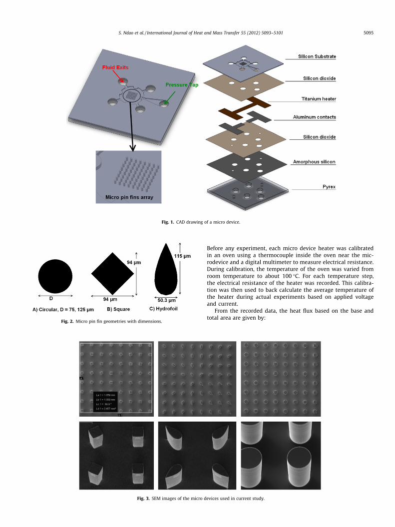
Fig. 3. SEM images of the micro d
Fig. 1. CAD drawing of a micro device.
Fig. 2. Micro pin fin geometries with dimensions.
S. Ndao et al. / International Journal of Heat and Mass Transfer 55 (2012) 5093–5101 5095
Before any experiment, each micro device heater was calibratedin an oven using a thermocouple inside the oven near the mic-rodevice and a digital multimeter to measure electrical resistance.During calibration, the temperature of the oven was varied fromroom temperature to about 100 �C. For each temperature step,the electrical resistance of the heater was recorded. This calibra-tion was then used to back calculate the average temperature ofthe heater during actual experiments based on applied voltageand current.
From the recorded data, the heat flux based on the base andtotal area are given by:
evices used in current study.

Fig. 4. Schematic representation of the experimental setup used in the current study.
Fig. 5. Boiling curve for jet impingement on a smooth surface, Tin = 26 �C,Tsat = 31 �C.
5096 S. Ndao et al. / International Journal of Heat and Mass Transfer 55 (2012) 5093–5101
q00total ¼Q conv
Atotalð2Þ
q00base ¼Q conv
Abaseð3Þ
where
Q conv ¼ Q applied � Qloss ¼ IVT � Qloss ð4Þ
and Atotal is the total surface area (base plus fins) and Abase is thebase (plan) area of the heater. Using 1-D conduction, the wall sur-face temperature was computed from the heater measured temper-ature using the following equation:
Tw ¼ Th �q00basetoxide
ksð5Þ
where Tw and Th are average temperatures of the base (exposed tothe fluid) and the heater (Titanium heater), respectively. toxide isthe thickness of the oxide layer. The thickness of the silicon sub-strate (20 lm) was not included because of the insignificant tem-perature drop across it over the range of heat fluxes studied. Thesubcooled temperature is defined as:
DTsub ¼ Tsat � Tf ;in ð6Þ
while the wall superheat is given by:
DTsat ¼ Tw � Tsat ð7Þ
The Reynolds number based on the jet diameter was calculatedfrom the following definition:
Red ¼qVdj
l ð8Þ
All thermodynamics properties were computed based on jet inletconditions.
Heat loss in the experiments was estimated using COMSOL Mul-tiPhysics. Detailed description of the model has already been pub-lished in [26]. Average calculated heat losses were in the order of29.5–38.5%. Using standard propagation of error analysis methoddeveloped by Kline and McClintock [27], maximum uncertainties
on the heat flux, temperature, and mass flowrate were estimatedto be about 6.5%, 2 �C, and 0.5%, respectively.
3. Results and discussion
3.1. Flow boiling jet impingement heat transfer on smooth surfaces
Flow boiling experiments with R134a were carried out for twodifferent saturation pressures, 820 kPa and 1090 kPa, correspond-ing to saturation temperatures of approximately 31 �C and 45 �C,respectively. Three Reynolds numbers, Re = 13,600, 28,300, and50,100, corresponding to jet velocities ranging from 1.1–4.05 m/swere investigated.
Fig. 5 shows the boiling curve for jet impingement on a smoothsurface. At wall temperatures below saturation temperature, theheat transfer mechanism was purely single-phase convection;

Fig. 7. Boiling curve for jet impingement on a smooth surface – effects of velocity,Tin = 26 �C, Tsat = 31 �C.
S. Ndao et al. / International Journal of Heat and Mass Transfer 55 (2012) 5093–5101 5097
hence the heat transfer coefficients were independent of heat flux.Further increases in the heat flux increased the wall temperaturesabove the saturation temperature without any sign of boiling.Hence, in this region, Tw–Tsat < 17 �C, single-phase convective heattransfer was still prelevant. The prelevance of single-phase heattransfer at wall temperatures above saturation temperature wasdue to the highly wetting characteristics of R134a and to the al-most perfectly smooth surface of silicon, the combination of whichdelayed the formation of vapor pockets on the heated surface. At ahigher wall superheat of about 19 �C, onset of nucleate boiling(ONB) occured. Incipient boiling was marked by a sharp increasein the heat transfer coefficients characterized by a large wall super-heat drop for a relatively constant heat flux. The observed temper-ature excursion was due to the activation of nucleation sites. Theflow boiling regime, following the ONB, was characterized by highheat transfer coefficients due to the combined effects of inducedmixing due to violent release of vapor bubbles along with the asso-ciated latent heat of vaporization.
Fig. 6 shows a boiling curve similar to Fig. 5. However, this timeafter sustained boiling, the heat fluxes were subsequently reduced.Reducing the heat flux decreased the wall superheat within theboiling and single-phase region without any manifestation of tem-perature overshoot, thus, exhibiting a phenomenon known as boil-ing hysteresis. Reducing power of the heater resulted initially to areverse path of the boiling curve, which then bypassed the temper-ature overshoot phenomenon to return to the single-phase region.The absence of temperature overshoot is largely attributed to thealready activated state of the nucleation sites. The slight tempera-ture jump at around wall superheat of 5 �C was probably caused byabrupt deactivation of some of the nucleation sites. The above-mentioned observation has been also found by other researcherssuch as [10]. Considering the uncertainties in the wall superheat(2 �C) and the stochastic nature of boiling heat transfer, thedecreasing heat flux in some cases did not follow exactly the samepath as the increasing heat flux curve.
Fig. 7 shows the boiling curves on smooth surfaces for variousjet exit velocities. For all case studied, increasing jet velocity re-sulted in boiling heat transfer augmentation. This enhancementcould be due to indirect single-phase effects in the boiling regime.The heat transfer augmentation could have been also caused byhigher velocities being able to resupply cold liquid to the heatedsurface allowing for more evaporative heat transfer. Wolf et al.[9] have found jet velocity to have no effect on the boiling heattransfer. In their experiments; however, the wall jet region contrib-uted to a major portion of the average heat transfer coefficients.
Fig. 6. Boiling curve for jet impingement on a smooth surface – increasing vsdecreasing heat flux, V = 1.1 m/s, Tin = 26 �C, Tsat = 31 �C.
The wall jet region could have possibly overshadowed the effectsof jet velocity as the bulk flow in the wall jet region may have sup-pressed complete departure of the bubbles. As also shown on thefigure, increasing jet exit velocity decreased temperature over-shoot. Ma and Bergles [7] attributed this observation to high heattransfer coefficients with increasing velocities. From the above dis-cussion, it can be concluded that jet impingement flow boiling atthe stagnation point displays distinct characteristics in which jetvelocity plays an important role.
Because of the nature of nucleate boiling, surface treatment andsurface conditions have significant effects on the boiling heattransfer characteristics. As shown in Fig. 8, surface condition hada significant effect on the boiling regime with the boiling curvessignificantly shifting as a result of surface aging and wear. In thepresent experiment, between the first experimental run to the sec-ond one, 18 days later, the micro device was safely kept inside awafer casset. Aging and surface wear due to the experimental runsmay have roughened the micro device surface, resulting in theenhancement of the boiling heat transfer coefficients. Similarobservations have been also made by other researchers, [7,10].Zhou et al. [10] have presented significant shifts of the boilingcurve in a time span of about 9 h and causing lower incipient boil-ing superheat. Ma and Bergles [7] have also observed significantday-to-day shifts in the fully developed boiling curves. Similar to
Fig. 8. Boiling curve for jet impingement on a smooth surface – effects of aging,Tin = 26 �C, Tsat = 31 �C.

Fig. 9. Boiling curve for jet impingement on a smooth surface – effects of saturationpressure.
Fig. 10. Flow boiling jet impingement on micro pin fins, V = 1.7 m/s, Tin = 26 �C,Tsat = 31 �C.
5098 S. Ndao et al. / International Journal of Heat and Mass Transfer 55 (2012) 5093–5101
the current findings, the general trend of the boiling curve shiftswas toward an enhancement of the boiling heat transfer coeffi-cients with time. Aging can lead to changes in surface chemistryand more roughness of the heated surface, thus, increasing theprobability of potential nucleation sites.
The effect of saturation pressure on the boiling characteristic ofjet impingement on smooth surfaces is shown in Fig. 9 for twopressures, 820 kPa and 1090 kPa. Note that boiling points at wallsuperheat below 0 �C could be due to experimental discrepanciesand uncertainties on the wall superheat temperature (about±2 �C). Based on the results, increasing the saturation pressurehad an effect of increasing the boiling performance. Note that therelatively larger heat flux at the ONB for the higher pressure canbe attributed to larger inlet subcooling. A considerable reductionof temperature overshoots (incipient superheat) was also observedas a result of the increase in saturation pressure. These findings arevery much in agreement with the literature (some of which havebeen listed in [28]), in which it has been shown that increase insaturation pressure resulted in increase of the heat transfercoefficients.
Fig. 11. Boiling curve – smooth vs enhanced surface, V = 2.2 m/s, Tin = 26 �C,Tsat = 31 �C.
3.2. Flow boiling jet impingement heat transfer on micro pin fins
The enhancement surfaces used in this study consist of circularmicro pin fins of diameters 125 lm and 75 lm, hydrofoil micro pinfins, and square micro pin fins. Flow boiling experiments werecarried out at a saturation pressure of 820 kPa, corresponding toa saturation temperature of approximately 31 �C. Four velocitiesranging from 1.1–4.0 m/s were investigated and presented. Notethat unless otherwise mentioned, the term ‘‘heat flux’’ refers tothe heat flux based on the base area.
Fig. 10 shows the boiling curve for jet impingement on circularmicro pin fins of diameters 125 lm. The boiling curve was similarto that of flow boiling jet impingement on a smooth surface, and,hence, a similar description is applied. However, we can notetwo major differences, the most important one being the absenceof a temperature overshoot. Transition from single-phase to two-phase regime occured relatively very smoothly. This characteristicof flow boiling jet impingement on micro pin fins can be attributedto a few factors. The first being the increase of possible nucleationsites as a result of surface augmentation. The added surface in-creased the probability for a wider range of cavity sizes, thusincreasing the probability for nucleation. Besides the additionalsurface, the mere presence of the micro pin fins presented oppor-
tunities for more active cavities. Another source of increased nucle-ation sites is the DRIE microfabrication process used to fabricatethe pin fins. DRIE produced deep vertical sidewalls on the siliconwafer with characteristic peak-to-peak roughness of about0.3 lm, forming cavities which could act as nucleation sites. Thismay suggest that surface condition played an even more importantrole than fluid wettability on boiling inception. The second distinc-tion between the present boiling curve and that of a smooth sur-face is the difference in thermal performance. Boiling jetimpingement on micro pin fins accommodated higher heat fluxesfor a given wall superheat.
Fig. 11 shows a comparison between flow boiling jet impinge-ment on circular micro pin fins (D = 75 lm, area = 7.46 mm2) anda smooth surface (area = 4.0 mm2). Heat transfer enhancementsas high as 1.6 and 2.4 at a velocity of 2.2 m/s were observed forarea enhancements of 1.86 and 2.44, respectively. Unlike the sin-gle-phase heat transfer results [26], heat transfer enhancementswere slightly smaller than the area enhancements. This is possiblybecause nucleate boiling is more important than convective boilingin the boiling regime; hence, most of the enhancement occurred inareas of high active nucleation site density. Similar observationrelated to the heat transfer enhancement has also been reportedin [29] for droplet impingement. At higher velocities, the heat

Fig. 12. effects of velocity on the boiling curve – square pin fins, tin = 26 �c,tsat = 31 �c.
Fig. 13. Hydrofoil pin fins boiling curve and CHF, Tin = 26 �C, Tsat = 36 �C.
Fig. 14. Boiling curve based on base area – effects of pin fin diameter, V = 2.2 m/s,Tin = 26 �C, Tsat = 31 �C.
S. Ndao et al. / International Journal of Heat and Mass Transfer 55 (2012) 5093–5101 5099
transfer enhancements are expected to be greater than the areaenhancements. Besides the suppression of temperature overshootsand higher heat transfer coefficients, the ONB was shown to occurat a relatively lower wall superheat when compared to flow boilingjet impingement on smooth surfaces. This is also due to a combina-tion of higher heat transfer coefficients and enhanced nucleateboiling. Note that kinks on the circular micro pin fins plot wereprobably from experimental uncertainties due to shifts in contactresistances or perhaps from small temperature excursions due toactivation of new nucleation sites.
Fig. 12 shows the effects of velocity on the boiling curves of thesquare pin fin micro device. Similar to jet impingement on smoothsurfaces, increasing jet exit velocity increased the heat transfercoefficients while reducing the wall superheat at the ONB. This isvery beneficial for electronics cooling as it reduces thermal stressand delays CHF. Except for the lowest jet velocity plot, no temper-ature overshoot was observed for the same reasons mentioned ear-lier. Temperature overshoot at the lowest velocity, V = 1.1 m/s, isdue to lower heat transfer coefficients and possibly the inabilityof the fluid to penetrate deep enough to the base of the pin fin ar-ray. As the jet exit velocity was increased, temperature overshootsstarted to disappear. Temperature overshoots are also expected todecrease with increasing area enhancement for a given jet exitvelocity.
High heat transfer coefficients were achieved with flow boilingjet impingement on micro pin fins. Heat transfer coefficientsexceeding 150,000 W/m2 K were observed at a relatively lowvelocity of 2.2 m/s with the large (D = 125 lm) circular micro pinfins. Heat fluxes above 200 W/cm2 for wall superheat less than15 �C and inlet subcooling as little as 5 �C have been demonstrated.Higher heat fluxes could have been achieved; however, to avoiddevice burnout, the experiments were carried out at heat fluxesmuch below expected CHF condition. One set of experimentswhere CHF was believed to have been occured is shown inFig. 13 for the hydrofoil pin fins. For an inlet subcooling of about10 �C, CHF was reached at a heat flux of 275 W/cm2.
Fig. 14 shows the effects of fin diameter on the boiling curvebased on the base area. The larger diameter micro pin fins outper-formed the smaller diameter micro pin fins. For a given jet exitvelocity, boiling heat transfer enhancement could have beencaused by area enhancement, nucleation site count, and indirectsingle-phase convection. The enhancement factors in this casewere approximately the same as the area enhancement, about1.3. Based on earlier discussion comparing enhanced to smooth
surface, it can be concluded that nucleate boiling enhancementplayed an important role here besides area enhancement. Largersurface area inherently increases the probability of active nucle-ation sites. The larger diameter micro pin fins were therefore morelikely to exhibit higher nucleation site density and, thus, betternucleate boiling performance. If single-phase convection had anyeffects, it would have been manifested possibly by better perfor-mance of the larger diameter micro pin fins when the two boilingcurves (circular pin fins – D = 125 and 75 lm) based on the totalarea were compared as done in Fig. 15. The larger the diameterof the pin fin is, the smaller the flow area will be. Smaller flow areameans higher local velocities within the pin fin array for a given jetvelocity and, hence, higher average heat transfer coefficients. How-ever, as seen in Fig. 15, the two boiling curves were almost identi-cal, with perhaps a slightly higher performance of the largerdiameter micro pin fins. Similar to the single-phase experiments[26], it can be concluded that the heat transfer enhancement acrosspin fins was largely due to area enhancement (by the addition ofmore nucleation sites) and nucleate boiling enhancement. Flowvisualization; however, will be necessary to validate this conclu-sion, as flow visualization will indicate whether there were hiddeneffects of velocity on the boiling performance such as increase inbubble departure frequency.

Fig. 15. Boiling curve based on total area – effects of pin fin diameter, V = 2.2 m/s,Tin = 26 �C, Tsat = 31 �C.
Fig. 16. Boiling curve based on base area – effects of pin fins geometry, Tin = 26 �C.
5100 S. Ndao et al. / International Journal of Heat and Mass Transfer 55 (2012) 5093–5101
Fig. 16 shows a comparison of the various micro pin fins consid-ered in this study. The circular pin fins and the square pin finsshowed better thermal performance than the hydrofoil pin fins.Note that the hydrofoil pin fins’s boiling curve appearance to behigher than that of the square pin fins was due the higher satura-tion temperature (e.g., higher subcooling) used in the former.Based on these results, area enhancement played a very importantrole in flow boiling jet impingement. In the case of single-phase jetimpingement, heat transfer coefficients enhancement was ob-served besides area enhancement [26], further supporting our ear-lier conclusion that subcooled nucleate boiling was the dominantheat transfer mechanism in flow boiling experiments.
4. Conclusions
Flow boiling heat transfer experiements were carried out tostudy the flow boiling heat transfer mechanisms of jet impinge-ment on smooth and enhanced surfaces. The effects of saturationpressure, heat flux, Reynolds number, pin fin geometry, pin fin ar-ray configuration, and surface aging on flow boiling heat transfercharacteristics have been presented and discussed.
Flow boiling jet impingement on smooth surfaces is character-ized by large temperature overshoots, exhibiting boiling hysteresis.
Subcooled nucleate boiling was concluded to be the dominant heattransfer mechanism. Both the ONB and the fully-developed flowboiling heat transfer coefficients have been found to increase withincreasing Re, while the wall superheat decreased with increasingRe. Increasing Re and saturation pressure showed decreases in tem-perature overshoots. Surface condition and surface aging were alsofound to have significant effects on the fully developed boiling re-gime with the boiling curves significantly shifting causing lowerincipient boiling superheat and higher heat transfer coefficients.
Flow boiling jet impingement on enhanced surfaces is character-ized by the suppression of temperature overshoots. Transition fromsingle-phase to the two-phase boiling occured relatively smoothly,hence, suppressing any boiling hysteresis. When compared tosmooth surfaces, boiling jet impingement on the micro pin finsaccommodated higher heat fluxes for a given wall superheat.Two-phase heat transfer coefficients exceeding 150,000 W/m2 Kwere observed at a relatively low velocity of 2.2 m/s with the large(D = 125 lm) circular micro pin fins using R134a. Besides the sup-pression of temperature overshoots and higher heat transfer coeffi-cients, the ONB was shown to occur at a relatively lower wallsuperheat when compared to flow boiling jet impingement onsmooth surfaces. Heat transfer enhancement was largely due to areaenhancement and nucleate boiling enhancement with subcoolednucleate boiling being the dominant heat transfer mechanism.
Acknowledgments
The authors acknowledge the financial support of Office of Na-val Research through a MURI grant, Grant No. N00014–07-1–0723,entitled ‘‘System-Level Approach for Multi-Phase, Nanotechnol-ogy-Enhanced Cooling of High-Power Microelectronic Systems.’’The authors would like to also acknowledge support from theDepartment of Mechanical, Aerospace, and Nuclear Engineeringat Rensselaer Polytechnic Institute.
This work was performed in part at the Cornell NanoScale Facil-ity, a member of the National Nanotechnology Infrastructure Net-work, which is supported by the National Science Foundation(Grant ECS-0335765).
References
[1] H. Martin, Heat and mass transfer between impinging gas jets and solidsurfaces, Adv. Heat Transfer 13 (1977) 1–60.
[2] K. Jambunathan, E. Lai, M.A. Moss, B.L. Button, A review of heat transfer datafor single circular jet impingement, Int. J. Heat Fluid Flow 13 (2) (1992) 106–115.
[3] B.W. Webb, C.-F. Ma, Single-phase liquid jet impingement heat transfer, Adv.Heat Transfer 26 (1995) 105–217.
[4] S.V. Garimella, Heat transfer and flow fields in confined jet impingement, Ann.Rev. Heat Transfer 11 (1999) 413–494.
[5] B. Agostini, M. Fabbri, J.E. Park, L. Wojtan, J.R. Thome, B. Michel, State of the artof high heat flux cooling technologies, Heat Transfer Eng. 28 (2007) 258–281.
[6] A.B. Cohen, R. Bahadura, M. Iyengar, Least-energy optimization of air-cooledheat sinks for sustainability-theory, geometry and material selection, Energy31 (2006) 579–619.
[7] C.F. Ma, A.E. Bergles, Jet impingement nucleate boiling, Int. J. Heat MassTransfer 29 (8) (1986) 1095–1101.
[8] I. Mudawar, D.C. Wadsworth, Critical heat flux from a simulated electronicchip to a confined rectangular impinging jet of dielectric liquid, Int. J. HeatMass Transfer 34 (1991) 1465–1480.
[9] D.H. Wolf, F.P. Incropera, R. Viskanta, Local jet impingement boiling heattransfer, Int. J. Heat Mass Transfer 39 (7) (1996) 1395–1406.
[10] D.W. Zhou, C.F. Ma, J. Yu, Boiling hysteresis of impinging circular submergedjets with highly wetting liquids, Int. J. Heat Fluid Flow 25 (2004) 81–90.
[11] P.F. Sullivan, S. Ramadhyani, F.P. Incropera, Use of smooth and roughenedspreader plates to enhance impingement cooling of small heat sources withsingle circular liquid jets, Topics in Heat Transfer HTD-vol. 206-2 (1993) 103–110.
[12] S.V. Ekkad, D. Kontrovitz, Jet impingement heat transfer on dimpled targetsurfaces, Int. J. Heat Fluid Flow 23 (2002) 22–28.
[13] K.L. Teuscher, S. Ramadhyani, F.P. Incropera, Jet impingement cooling of anarray of discrete heat sources with extended surfaces, Enhanced CoolingTechniques for Electronics Applications HTD-vol. 263 (1993) 1–10.

S. Ndao et al. / International Journal of Heat and Mass Transfer 55 (2012) 5093–5101 5101
[14] Y. Kondo, H. Matsushina, T. Komatsu, Optimization of pin-fin heat sinks forimpingement cooling of electronic pakages, IEEE Trans. Compon. Pack.Technol. 23 (2000) 240–246.
[15] L.A. Brignoni, S.V. Garimella, Experimental optimization of confined air jetimpingement on a pin fin heat sink, IEEE Trans. Compon. Pack. Technol. 22(1999) 399–404.
[16] H.A. El-Sheikh, S.V. Garimella, Heat transfer from pin-fin heat sinks undermuliple impinging jets, IEEE Trans. Compon. Pack. Technol. 23 (2001) 113–120.
[17] H.A. El-Sheikh, S.V. Garimella, Enhancement of air jet impingement heattransfer using pin-fin heat sinks, IEEE Trans. Compon. Pack. Technol. 23 (2000)300–308.
[18] J.G. Maveety, H.H. Jung, Heat transfer from square pin-fin heat sinks using airimpingement cooling, IEEE Trans. Compon. Pack. Technol. 25 (3) (2002) 459–469.
[19] S.P. Jang, S.J. Kim, Fluid flow and thermal characteristics of a microchannelheat sink subject to an impinging air jet, J. Heat Transfer 127 (2005) 770–779.
[20] H.Y. Li, S.M. Chao, G.L. Tsai, Thermal performance measurement of heat sinkswith confined impinging jet by infrared thermography, Int. J. Heat MassTransfer 48 (2005) 5386–5394.
[21] D.K. Kim, S.J. Kim, J.K. Bae, Comparison of thermal performaces of plate-fin andpin-fin heat sinks subject to an impinging flow, Int. J. Heat Mass Transfer 52(2009) 3510–3517.
[22] D.Y. Lee, K. Vafai, Comparative analysis of jet impingement and microchannelcooling for high heat flux applications, Int. J. Heat Mass Transfer 42 (1999)1555–1568.
[23] S. Ndao, Single-phase and flow boiling heat transfer of jet impingement onsmooth and enhanced micro structured surfaces, PhD thesis, RensselaerPolytechnic Institute, Troy, NY, 2010.
[24] D. Wadsworth, I. Mudawar, Enhancement of single-phase heat transfer andcritical heat flux from an ultra-high-flux simulated microelectronic heatsource to a rectangular impinging jet of dielectric liquid, J. Heat Transfer 114(3) (1992) 764–768.
[25] D. Copeland, Single-phase and boiling cooling of small pin fin arrays bymultiple nozzle jet impingement, J. Electron. Pack. 118 (1996) 21–26.
[26] S. Ndao, H.J. Lee, Y. Peles, M.K. Jensen, Heat transfer enhancement from micropin fins subjected to an impinging jet, Int. J. Heat Mass Transfer 55 (1–3)(2012) 413–421.
[27] S.J. Kline, F.A. McClintock, Describing uncertainties in single sampleexperiments, Mech. Eng. 75 (1953) 3–8.
[28] K.N. Rainey, S.M. You, S. Lee, Effect of pressure, subcooling, and dissolved gason pool boiling heat transfer from microporous surfaces in FC-72, J. HeatTransfer 125 (1) (2003) 75–83.
[29] C.H. Amon, S.C. Yao, C.F. Wu, C.C. Hsieh, Microelectromechanical system-Basedevaporative thermal management of high heat flux electronics, J. Heat Transfer127 (1) (2005) 66–75.