experience with modified aerospace reliability and quality ... · pdf filemodified aerospace...
TRANSCRIPT

I --- --.~ ---
DOE/NASAl20320-38 NASA TM-82803
Experience with
ASA-TM-82803 198200 11676
Modified Aerospace Reliability and Quality Assurance Method for Wind Turbines
William E. 'Klein National Aeronautics and Space Administrat ion Lewis Research Center
Work performed for U.S. DEPARTMENT OF ENERGY Conservation and Renewable Energy Division of Wind Energy Systems
Prepared for
B ARY COpy I r? 2 1982
LANGLEY RESEARf:H Ct:.NTER LIBRARY. NASA
HAMPTON, VIRGINIA
Nineth Annual Engineering Conference on Reliability Hershey, Pennsylvania, June 16-18, 1982
J
https://ntrs.nasa.gov/search.jsp?R=19820011676 2018-05-16T20:35:03+00:00Z

NOTICE
This report was prepared to docu ment work sponsored by the United States Government Neither the United States nor Its agent . the Uni ted States Department of Energy . nor any Federal employees . nor any of their contractors . subcontractors ortheir employees . makes any wa rranty . express or Implied. or assumes any legal liability or responslolli ty for the accuracy . completeness . or usefulness of any Information . apparatus . product or process di sclosed . or represents that Its use would not Infringe privately owned righ ts

- - --~-~--- ~-~----~' --
Experience with Modified Aerospace Reliability and Quality Assurance Method for Wind Turbines
William E. Klein National Aeronautics and Space Administration Lewis Research Center Cleveland, Ohio 44135
Work performed for U.S. DEPARTMENT OF ENERGY Conservation and Renewable Energy Division of Wind Energy Systems Washington, D.C. 20545 Under Interagency Agreement DE-AI01-76ET20320
Prepared for Nineth Annual Engineering Conference on Reliability Hershey, Pennsylvania, June 16-18, 1982
DOE/NASAl20320-$8 NASA TM-82803
'p:- I JIIYL-/ 9fftJ I

~~- -- --~-- ---
1982 ENGINEERING CONFERENCE ON RELIABILITY FOR THE ELECTRIC POWEH INDUSTRY
Experience with Modified Aerospace Reliability and Quality Assurance Method for Wind Turbines*
William E. Klein National Aeronautics and Space Administration
Lewis Research Center Cleveland, Ohio
Abstract Description of Original Design
This paper describes the original Safety, Reliability and Quality Assurance (SR&QA) approach developed for the first large wind turbine generator project, Mod OA. The SR&QA approach to be used had to assure that the machine would not be hazardous to the public or operating personnel, would operate unattended on a utility grid, would demonstrate reliable operation and would help establish the quality assurance and maintainability requirements for future wind turbine projects. Since the utlimate objective of the wind energy program is to provide wind power at a cost competitive with other energy sources, the final SR&QA activities were to be accomplished at a minimum of cost and manpower. The final approach consisted of a modified Failure Modes and Effects Analysis (FMEA) during the design phase, minimal hardware inspection during parts fabrication, and three simple documents to control activities during machine construction and operation. Five years experience has shown that this low cost approach has worked well enough that it should be considered by others for similar projects.
Introduction
The NASA Lewis Research Center is conducting research and development of large horizontal axis Wind Turbine Generators (WTG's) for the Department of Energy as one phase of the overall Federal Wind Energy Program. Wind turbines ranging in size from 100 kilowatts (kW) to 4000 kW have been designed and built as part of this program. Two machines of about 7200 kW are presently in the design stage. The object of the program is to develop wind turbines which will generate electricity at a cost which is competitive with alternatives, particularly oil. This paper describes the SR&QA approach originally developed for the first large wind turbine project, Mod OA, a 200 kW, l25-foot diameter machine. This project has been a combination of in-house and contracted effort and is a unique joining of aerospace technology and standard utility practices. This project formed the base for future development of large wind turbines and this SR&QA approach was subsequently applied to other NASA/DOE WTG projects.
*Revised version of NASA TM-79284, "Modified Aerospace Reliability and Quality Assurance Method for Wind Turbines," by William E. Klein presented at the Reliability and Maintainability Symposium, January 22-24, 1980.
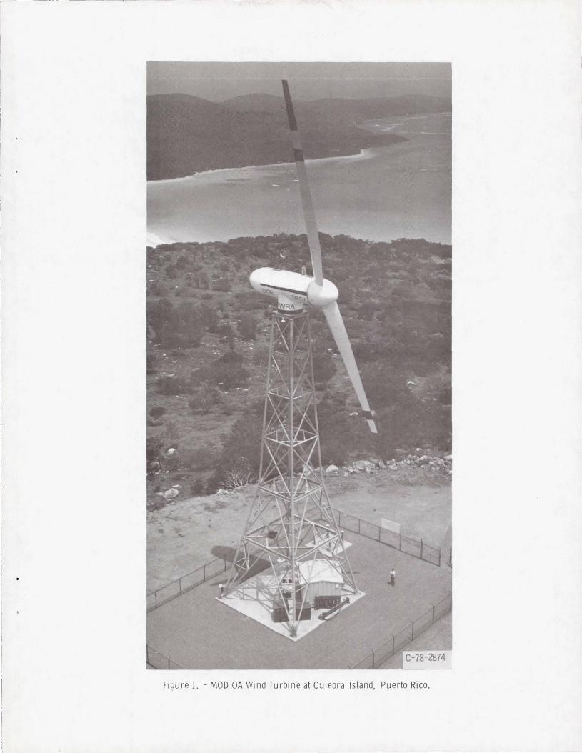
A photograph of one Mod OA machine, located on Culebra Island, Puerto Rico, is shown as Fig. 1. Three similar machines are located in Clayton, New Mexico, on Block Island, Rhode Island, and on Oahu, Hawaii. The two blades measure 125 feet, tip-to-tip. The hub centerline is 100 feet above ground level. The blades rotate at 40 rpm on two machines and 31.5 rpm on the other two machines. The blades are mounted on the rotor hub, as shown in the cutaway drawing included as Fig. 2. The pitch actuator pitches the blades through a set of bevel gears located inside the hub. The hub is attached to a low speed shaft which drives a speed increaser gearbox. In the original design, a high speed shaft transmitted power to V-belts which drove a synchronous alternator. Each machine is housed in an 8-foot diameter nacelle and is mounted on a turntable bearing located on top of a truss tower. A yaw drive system keeps the machine aligned with the wind.
In the original deSign, the wind turbine was controlled by a microprocessor, two closed loop servo systems, and a safety system. The microprocessor is the heart of the control system. It monitors machine status and wind conditions. When the wind speed reaches 10 mph, the microprocessor signals the pitch controller to start pitching the blades, gradually increasing blade rotation. When the alternator reaches synchronous speed, it is synchronized with the utility grid. After synchronization, the blades remain in the full power pOSition, generating increasing power as the winds increase, until the full output of 200 kW is reached at a wind speed of about 20 mph. As winds increase further, the blades pitch towards the feather position, spilling some of the wind, to maintain the 200 kW output.
If the power drops below -10 kW, the machine is shut down. If the wind speed increases above 40 mph, the machine is shut down to avoid high blade loads. When the wind speed drops back to 35 mph, the machine is restarted. The microprocessor also monitors several noncritical variables to shut the machine down if necessary.
In the original design, one closed loop servo system regulated the pitch of the blades. Blade pitch regulates machine speed from initial blade rotation until synchronization with the utility grid and regulates the power generated after synchronization. The second closed loop servo measured the difference between the actual wind direction and the nacelle direction to keep the machine aligned with the wind. The machine operates with the blades downwind and is kept aligned within 25° of the wind direction.

---~-- ------ ----
1982 ENGINEERING CONFERENCE ON RELIABILITY FOR THE ELECTRIC POWER INDUSTRY
The safety system, as the name implies, measures several operating variables, shutting the machine down if any of these variables go out of limits. These variables include speed, current, pneumatic and hydraulic pressures, several temperatures, and vibration. In most cases, the safety system shutdown signal goes into the microprocessor, but there are several signals which directly shut the machine down, regardless of what the microprocessor, the control system, or the safety system are doing.
Background
The Reliability and Quality Assurance (R&QA) Office was given the responsiblity to determine the safety, reliability, and quality assurance program that was to be initiated for these machines. The program had to be low cost and was further complicated by a unique combination of in-house and contract effort. The machine was designed in-house. Originally , this was a one machine program with options for two more machines. The schedule was very tight. Therefore, Lewis Research Center ordered a few long-lead items for all three machines, several additional items for two machines, and all hardware for the first machine . The Department of Energy quickly exercised the options for the additional two machines. The first machine was assembled in-house. The contractor was responsible for erection of the first machine, assembly and erection of the second machine (including the purchase of the remaining parts), and essentially all phases of the third machine. When the fourth machine was added later, the contractor was given total responsiblity for that machine. This meant that the SR&QA program had to operate under several combinations of in-house and contracted effort. The operation of the machine by the utility also had to be considered.
Safety and Reliability Approach
After considering numerous R&QA and safety techniques, a modified FMEA was chosen to be the main tool for listing and analyzing the various possible failures, and the results or effects of those failures. For the purposes of this project, the FMEA was performed for each functional mode of a system, subsystem, or component.
The analysis was qualitative in nature and the actual probability of occurance of a failure was not considered. However, the more probable failures were considered for possible redesign or addition of redundant systems, particularly for the failures that would have severe consequences. The basic ground rule used throughout the analysis was that no single point failure would be catastrophic even if a previous undetected failure had already occurred. For ~i ng le point failure items such as the blades, tower, ma chine bedplate, etc. it was verified that the item had been designed to a safe operating life with a significant factor of safety.
The FMEA has been used extenSively for design and operational safety reviews. It emphasizes the criticality of some hardware such as blades and hub. While performing the FMEA, it soon became obvious ~hat a significant overspeed would be the worst possible failure, since it could result in throwing a blade. The consequences of all other failures would be relatively minor by comparison. Based on this
2
finding, several design changes were made and redundant systems added. A disc brake was added to the high speed shaft to stop the rotor, even with the blades in the full power position. Also, a redundant overspeed switch was added that would operate the brake directly, rather than acting through the safety system as most of the other sensors do. The FMEA gives project management a qualitative evaluation of the degree of the risk the design imposes on both personnel and machine safety. Trade offs of degree of risk versus the need for additional redundancy or periodic inspection or mai ntenance can then be assessed. The FMEA has proven very useful when new design changes were being considered.
To complete the reliability phase of the original program, a simple Discrepancy Report (DR) form was developed as the main failure reporting system. A sample DR is included in Fig. 3. The DR form is also used to track failure analysis, when required, to assure initiation of eng ineering changes and to help control configuraton. The form is based on discrepancy and failure report forms used in earlier programs and works quite well .
Experience showed us that critical components need to be i nspected at the vendors plant during machining and assemb ly to save cost and schedule problems later. We also found that it was wise to perform some inspection and checkouts of the more important fabricated hardware, such as the switchgear. Where inspection at the vendors plant was not practical, receiving inspection activity was augmented. Highly stressed unique hardware such as the blades and hub were of particular concern. Further developments indicated the need to maintain dimensional records of critical components during assembly and maintenance operations to allow a continuing assessment of component performance in areas such as wear rates of bearings, deformation of structural elements, etc. The one area where it has not been necessary to perform much inspection is for commercial, off-the-shelf components. We have experienced very few difficulties in this area.
Two more activities round out the qua lity efforts on the project. An Engineering Work Order form is used to document changes made to the system. This form is virtually identical to the DR form in Fig. 3, except for the Material Review Board items. This form documents the change to be made and is used for configuration control. The form also assures all personnel that the project manager has given his approval to make the change. Finally, a daily log is kept for each phase of the project to record all significant activities.
Most of the above discussions relating to Discrepancy Reports, Engineering Work Orders, inspecton records (for recording dimensions, etc.) and the daily log was basically for our in-house efforts. However, we have been very successful in having each of our contractors and each utility use their own internal paperwork system to perform the intent of each of the above documents. The contractors maintain a daily log to comp lete the the R&QA requirements. Each utility maintains a daily log and reports all failures on their weekly summary reports. The reader can refer to Ref. 1 for more details on the original SR&QA program and how it was set up.
- ----- ---- - --- ---- -- - - -

1982 ENGINEERING CONFERENCE ON RELIABILITY FOR THE ELECTRIC POWER INDUSTRY
Early experince with the first machines indicated that several design changes were desireabJe. The contractor was made totally responsible ·for most of the changes, including the design, changing drawings, work coordination, etc. One example included changing the alternator to a direct drive system, eliminating a longer high speed shaft, t~o high speed bearings and the drive belts. This change has been made only on the fourth machine at this point. The project still desires to maintain the flexibilty of being able to change rotor speeds by changing the belts and pulleys on two of the machines. A decision has not been made on converting the fourth machine. A second example involved adding an additional wind speed sensor mounted on the top of the nacelle. This sensor axis is fixed parallel to the nacelle so that the sensed wind speed acts as a redundant check on both wind speed and direction. This eliminated the need to use signals from the meterological tower and greatly simplified the hardware that was needed to perform the redundant checks. A third example was to use the yaw error signal, which was already in the microprocessor, to command the yaw function of the machine. This completely eliminated one of the closed loop control systems. These last two changes, plus several more minor changes, made the microprocessor and the control program more complicated, but eliminated a large amount of electronics and a number of relays. Experience has shown that the microprocessor has been much more reliable than most of the other electronic hardware.
The above changes were listed for several reasons. The original SR&QA program maintained the desired controls on the work performed and the proper configuration control, while maintaining the required redundancy and maintaining safe operation. Each change was reviewed to be sure that it improved the reliability and/or safe operation of the machine. Each change was also thoroughly reviewed against the FMEA to be sure that the safety or reliability guidelines were not compromised. Because of the numerous changes to the program, we have just completed a contract which updated the FMEA. The FMEA was completely reviewed and updated as necessary. The periodic reviews performed prior to each change have fulfilled a useful function, because there were no safety problems or lack of redundancy uncovered during the update.
As the machines have gained operating time and federal manpower cutbacks have occurred, more and more of the maintenance and inspection activites have been contracted out. Contracts have been awarded to the utilities to do the routine maintenance and inspection activities. Also, the original machine contractor is taking over more and more .of the nonroutine maintenance and inspection activities. As this change has been taking place, virtually no change in the original SR&QA approach has been necessary.
A wind turbine experience data bank has been established for all of the wind turbines in the Department of Energy/NASA programs (Mod OA, Mod 1, Mod 2, etc.). A summary of all Discrepancy Reports, Engineering Work Orders, and Project Information Release reports (PIR's) are being entered into the data bank. (A PIR is an informal report that allows preliminary release of machine performance data, trade-off studies, design information, etc.) The
3
search program is very flexible and allows searches by system, sub-system, part, dates, machine number, plus many other choices. The program will also calculate MTBF for any desired category. This has proven very valuable and time saving when the operating experience on some part or system is desired. A printout of a sample search is included as Table 1.
Conclusion
The SR&QA approach described above was initiated on what was basically a research and development project and then revised and expanded as the project evolved. Part of the safety and reliability requirements are met .by performing a modified FMEA during the design phase. A Discrepancy Report is used to record all failures and discrepancies. Part of the quality requirements are met by performing some vendor inspections and inspecting all machined items and most of the fabricated items upon delivery. An inspection report is kept, recording all important dimensions. An Engineering Work Order form is used for configuration control. A daily log rounds out the quality control activities.
This SR&QA approach has been successful in assuring safe operation of the units and in demonstrating those aspects of standard safety, reliability and quality practices which are most applicable and cost effective to this type hardware. We have been getting good dimensional data on critical hardware and we have a good record of the configuration of each machine. The first Mod OA has accumulated 12,000 hours of synchronized time and has reached a Mean Time Between Failures (MTBF) of 360 hours. The accumulated run time of all four machines has reached 34,000 hours with a MTBF of 450 hours. Although this sounds low, several utilities have told us they feel this is excellent for this stage of a development program for a new power source. Experience has shown that the SR&QA approach we developed for the Mod OA program has been suffficiently successful that similar approaches are being instituted on the newer, more advanced machines leading to low cost commercialization of wind turbines.
The SR&QA approach described in this paper has worked well enough that we are recommending that such an approach be considered for other projects of similar complexity. The prime considerations are that the SR&QA approach needs to be simple, reasonable, and flexible.
Reference
1. W. E. Klein, "Modified Aerospace Reliability and Quality Assurance Methods for Wind Turbines," NASA TM-79284, Prepared for Annual Reliability and Maintainability Symposium, January 22-24, 1980.
Biography
William E. Klein, P.E. NASA Lewis Research Center 21000 Brookpark Road Cleveland, Ohio 44135

1982 ENGINEERING CONFERENCE ON RELIABILITY FOR THE ELECTRIC POWER INDUSTRY
Mr. Klein is the Product Assurance Manager for the 200 kW Wind Turbine Project, which is being " managed by the Lewi s Research Center for the Depa"rtment of Energy. Since 1977, he has been responsible for all reliability and quality assurance activities for this program. He is also Product Assurance Manager for a 7200-kW low-cost wind turbine project, an in-house low cost wind turbine project, and for the 100-kW wind turbine being used for supporting research and technology at Lewis Research Center's Plum Brook Station. In 1976 and 1977, he was Product Assurance Manager for the Centaur Launch Vehicle inertial guidance system. From 1974 through 1976, he was Flight Systems Safety Engineer for the Canadian Communication Technology Satellite and contract auditor for launch vehicle contracts. From 1970 through 1974 he was the Project Engineer and from 1964 through 1970 he was a System Engineer (Mechanical and Electrical) at two large test stands at the Plum Brook Station. Mr. Klein received "his Bachelor of Mechanical Engineering degree from General Motors Institute in Flint, Michigan, and his Master of Science in Mechanical Engineering degree from Case Institute of Technology, Cleveland, Ohio.
4

TABLE I. - SAMPLE DATA BANK SEARCH
DATE OF REQUEST---FEBRUARY 11. 1982
SAMPLE DATA BANK SEARCH FOR TM-82803 lOA-I. PITCH SYSTEM. FLUID COUPLING)
PROGRAM OA
REPORT TYPE FA IlURE
PART NAME FLUID COUPLING
MANUFACTURER
MACHINE NUMBER 1
MICROFICHE # 31
REPORT OATE DEC 3 77 1773371
SERIAL NUMBER
MODEL NUMBER
REFERENCE DOCUMENTS
REPORT NAME DR
SYSTEM PITCH
DRAWING NUMBER
DEUBLIN COUPLING LEAKING. DEUBLIN REPLACED.
PROGRAM OA
REPORT TYPE ~'ODIFICATION
PART NAME FLUID COUPLING
MANUFACTURER
~'ACHINE NUMBER 1
MICROFICHE # 40
REPORT DATE JAN 4 78(78004)
SERIAL NUMBER
MODEL NUMBER
REFERENCE DOCUMENTS EWO 2091
REPORT NAME DR
SYSTEM PITCH
DRAWING NUMBER
REPORT NUMBER 2030-1
SUB-SYSTEM HYD SUPPLY
SYNC TIME o
REPORT NUMBER 2038
SUB-SYSTEM HYD SUPPLY
SYNC TIME 11
COAXIAL FLOW LINE NOT CENTERED---RUBBING ON WIRES IN 40 RPM SLIP RING. COLLAPSED SPONGE MATERIAL WHICH CENTERS DEUBLIN IN BRACKET
PROGRAM MICROFICHE # REPORT NAME o A 69 DR
REPORT TYPE REPORT DATE SYSTEM FAILURE SEP 11 78(78254) PITCH
PART NAME SERIAL NUMBER DRAWING NUMBER FLUID COUPLING
MANUFACTURER
~' ACHINE NUMBER 1
MODEL NUMBER
REFERENCE DOCUMENTS EWO 2133
H.P. DEUBLIN LEAKS. H.P . DEUBLIN REPLACED.
PROGRAM OA
REPORT TYPE FAILURE
PART NAME FLUID COUPLING
MANUFACTURER
MACHINE NUMBER 1
MICROFICHE # 143
REPORT DATE AUG 13 79(79225)
SERIAL NUMBER
MODEL NUMBER
REFERENCE DOCUMENTS
REPORT DR
SYSTEM PITCH
DRAWING
HIGH PR ESSURE DEUBLIN COUPLING FAILED.
NAME
NUMBER
REPORT NUMBER 2066
SUB-SYSTEM HYD SUPPLY
SYNC TIME 1873
REPORT NUMBER 2099
SUB-SYSTEM HYD SUPPLY
SYNC TIME o
1- ----- ---,---- ----- - - - - ----
Figure 1. - MOD OA Wind Turbine at Culebra Island, Puerto Rico.
-,
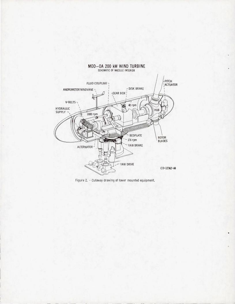
MOD-OA 200 kW WIND TURBINE SCHEMATIC OF NACELLE INTERIOR
FLUID COUPLING -, I
ANEMOMETER/WINDVANE .., I r DISK BRAKE
I
V-BELTS ""\
HYDRAULIC SUPPLY ~\
\ \ , GEAR BOX I
'- I
Figure 2. - cutaway drawi ng of tower mounted equipment.
C D-12362-44
,
__ J

CONTRAC T N O . D. R. NO .
FA CI L ITY C-.A<;II:;?>P DISCREPANCY REPORT 20b0
PART NO . R~E~ P~(&.; ~6. oft-~ (
, A-G2.YS USEe ON DWG .
k OJE N G o TE C H SE RVI CES DATE ? EQU IP .
svy;.cM-~p If SE:'P7 S-y<, CJ R6QA CJ CONTRACTOR - REPO RTER NOTIF IED AFFECTS FLI GHT HAROWARE MR iltE QUI REO D YES CJ NO
~YES 'I NO PROJ ENG ---- R60A ___ _ MRB REQUIREO CJVES CJ NO
OISCREPAN CY DESC RIP TION (Refer to ~opIicabie dt8wing ~nd pt'OCeclJre (Mlr_ or team
;U~ d:.,p TJ2U£U;.J .:27fJ-/LTO ) Sl'1UH11J6 [p.j
MR/ MRB OISPOSIT$ _
t:::-;P~c:-e # ,,P Dez;~.u ~ PJdloLA/7 3 ,
MR/ MRB
Cl P R OJ ENG D R6QA o TEC H SERVICES O CONTR ACTOR
COR RE CTIvE ACTION TECH SERVICES OU AL ITY
SHOP'/ PLA NNER BUY-OF" CONTROL
.tJ.~-I) f } /// J /)" ; FINA L BUY - OFF
~ROJ ENG je -)(..Y~..../--DR6QA DCONT"ACTOR
NASA-C·1 2 (Rev. 2.75)
Figure 3. - Typical discrepancy report.

1-- . -~- ----_ .. , -- _ ._- - - _. __ .. _ -----
1. Report No. I 2. Government Accession No. 3. Recipient's Catalog No.
NASA TM-82803 4. Title and Subtitle 5. Report Date
EXPERIENCE WITH MODIFIED AEROSPACE RELIABILITY
AND QUALITY ASSURANCE METHOD FOR WIND TURBINES 6. Performing Organization Code
776-33-41
7. Author(s) B. Performing Organization Report No.
William E. Klein E-1142
10. Work Unit No.
9. Performing Organization Name and Address
National Aeronautics and Space Administration 11 . Contract or Grant No.
Lewis Research Center
Cleveland, Ohio 44135 13. Type of Report and Period Covered
12. Sponsoring Agency Name and Address Technical Memorandum U. S. Department of Energy Di vision of Wind Energy Systems 14. Sponsoring Agency ~ Report No.
Washington, D. C. 20545 OOE/ NASA/ 20320-38 15. Supplementary Notes
Prepared under Interagency Agreement DE- AI01-76ET20320. Prepar ed for Nineth Annual Engineering Conference on Reliability, Hershey, Pennsylvania, June 16-18, 1982. This repor t is a revised version of NA SA TM-79284, "Modified Aerospace Reliability and Quality Assurance Method for Wind Turbines, " by William E. Klein presented at the Reliability and Maintainability Symposium, January 22-24, 1980.
16. Abstract
This paper describes the original Safety, Reliability and Quality Assurance (SR&OA) approach
developed for the first large wind turbine generator project, Mod OA. The SR&Q.A approach to
be used had to assure that the machine would not be hazardous to the public or operating person-
nel, would operate unattended on a utility grid, would demonstrate reliable operation and would
help establish the quality assurance and maintainability requirements for future wind turbine
projects. Since the utlimate objective of the wind energy program is to provide wind power at a
cost competitive with other energy sources, the final SR&QA activities were to be accomplished
at a minimum of cost and manpower. The final approach consisted of modified Failure Modes
and Effects AnalYSis (FMEA) during the design phase, minimal hardware inspection during parts
fabrication , and three simple documents to control activities during machine construction and
operation. Five years experience has shown that this low cost approach has worked well enough
that it should be considered by others for similar projects.
17. Key Words (Suggested by Author(s)) 18. Distribution Statement
System safety; FMEA; Safety; Low costs; Unclassified - unlimited
Hazard analysis; Methodology; Quality STAR Category 38
assurance; Reliability DOE Category UC-60
19. Securit y Classif. (of this report ) 20. Security Classi f . (of this page) 21 . No. of Pages 22. Price .
Unclassified Unclassified
• For sale by the Nati onal Techn ical Informa tion Service , Springfie ld , Virg inia 22161
---- ._------- ---. -----

11 11 1 111111 1~~~rllI111~llrfl]ll~fll~r~lllm 111111I111I 3 1176 00502 7132
----