expansion joints mageba modular expansion joints – the ... · mageba modular expansion joints –...
TRANSCRIPT
Expansion Joints
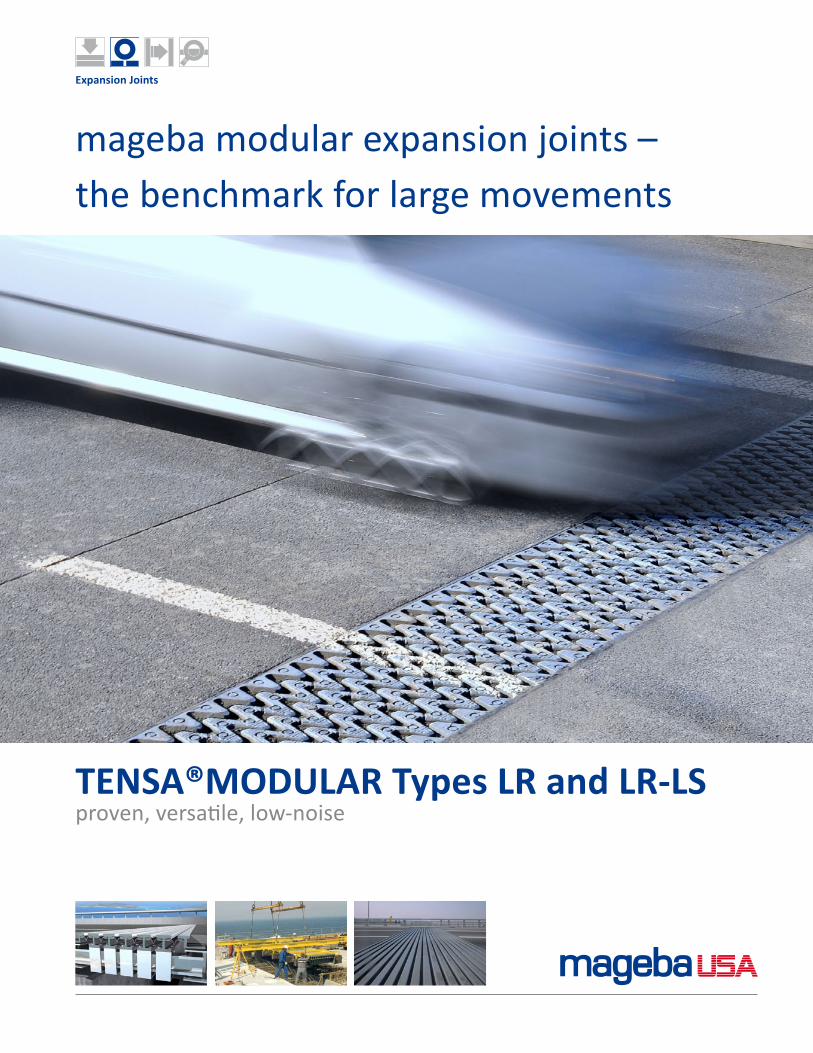
TENSA®MODULAR Types LR and LR-LSproven, versatile, low-noise
mageba modular expansion joints – the benchmark for large movements
2
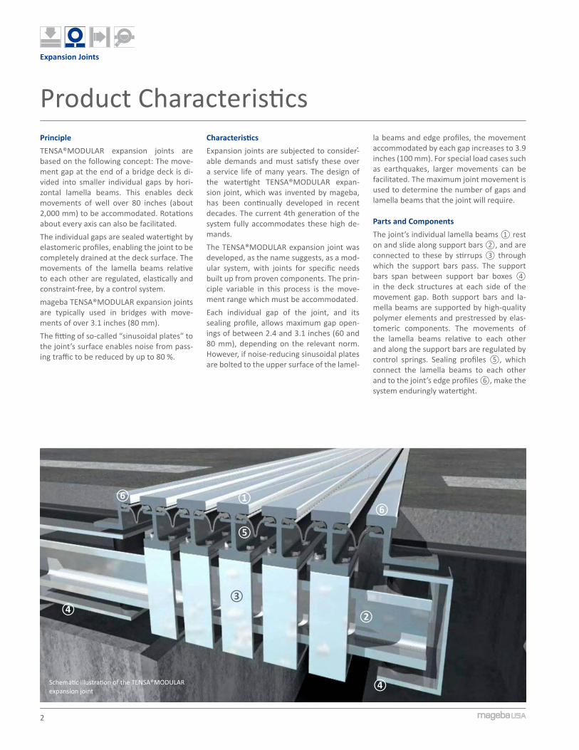
Schematic illustration of the TENSA®MODULAR expansion joint
Expansion Joints
Product CharacteristicsPrincipleTENSA®MODULAR expansion joints are based on the following concept: The move-ment gap at the end of a bridge deck is di-vided into smaller individual gaps by hori-zontal lamella beams. This enables deck movements of well over 80 inches (about 2,000 mm) to be accommodated. Rotations about every axis can also be facilitated.The individual gaps are sealed watertight by elastomeric profiles, enabling the joint to be completely drained at the deck surface. The movements of the lamella beams relative to each other are regulated, elastically and constraint-free, by a control system.mageba TENSA®MODULAR expansion joints are typically used in bridges with move-ments of over 3.1 inches (80 mm).The fitting of so-called “sinusoidal plates” to the joint’s surface enables noise from pass-ing traffic to be reduced by up to 80 %.
CharacteristicsExpansion joints are subjected to consider-able demands and must satisfy these over a service life of many years. The design of the watertight TENSA®MODULAR expan-sion joint, which was invented by mageba, has been continually developed in recent decades. The current 4th generation of the system fully accommodates these high de-mands.The TENSA®MODULAR expansion joint was developed, as the name suggests, as a mod-ular system, with joints for specific needs built up from proven components. The prin-ciple variable in this process is the move-ment range which must be accommodated.Each individual gap of the joint, and its sealing profile, allows maximum gap open-ings of between 2.4 and 3.1 inches (60 and 80 mm), depending on the relevant norm. However, if noise-reducing sinusoidal plates are bolted to the upper surface of the lamel-
la beams and edge profiles, the movement accommodated by each gap increases to 3.9 inches (100 mm). For special load cases such as earthquakes, larger movements can be facilitated. The maximum joint movement is used to determine the number of gaps and lamella beams that the joint will require.
Parts and ComponentsThe joint’s individual lamella beams ① rest on and slide along support bars ②, and are connected to these by stirrups ③ through which the support bars pass. The support bars span between support bar boxes ④ in the deck structures at each side of the movement gap. Both support bars and la-mella beams are supported by high-quality polymer elements and prestressed by elas-tomeric components. The movements of the lamella beams relative to each other and along the support bars are regulated by control springs. Sealing profiles ⑤, which connect the lamella beams to each other and to the joint’s edge profiles ⑥, make the system enduringly watertight.
①
②
③④
④
⑤
⑥⑥

3
3
21
54
Expansion Joints
Client Benefits
1 Installation works on the Run Yang Bridge2 TENSA®MODULAR joint featuring sinusoidal
plates – in service3 Installed 24-gap joint allowing 75.6 inches (1,920
mm) of movement and weighing 90,390 lb4 Control system with control springs and
connection plates5 Recesses prior to concreting
Highlights• Allows free movements in all direc-
tions and rotations about every axis• Completely watertight system with
drainage at the bridge surface• Versatile and freely adaptable to suit
client’s wishes• Can be used on all types of bridges• Based on well-proven and thoroughly
tested components and parts• Low-noise when fitted with sinusoidal
plates
Design• Welding is avoided in all highly stressed
connections, increasing durability.• All of the joint’s well-proven wear parts
are bolted in place, and can be replaced if necessary with little effort and without disrupting traffic.
• For the installation of the joint, only rela-tively small recesses are required in the bridge structure at each side. Thanks to its asymmetric design, it can be easily adapted to suit specific circumstances.
• The orientation of the support bars, in the direction of the deck’s span, simpli-fies the placing of the connecting deck reinforcement.
Functionality• All parts of the joint are elastically pre-
stressed, making them highly resistant to fatigue.
• The elastic gap control system increases the service life of the entire joint by damping the impact loading from over-rolling traffic.
• The joint’s prestressed connections damp impacts and vibrations, while facilitating large transverse movements, vertical dis-placements and rotations.
• Sinusoidal plates, which can optionally be fitted to the surface of the joint, reduce noise from over-rolling traffic by up to 80%, making the joint suitable for use in noise-sensitive areas.
4
1
2
Expansion Joints
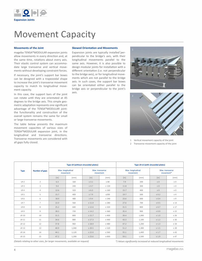
1 Vertical movement capacity of the joint2 Transverse movement capacity of the joint
Movements of the Jointmageba TENSA®MODULAR expansion joints allow movements in every direction and, at the same time, rotations about every axis. Their elastic control system can accommo-date large transverse and vertical move-ments without developing constraint forces.If necessary, the joint’s support bar boxes can be designed with a trapezoidal shape to increase the joint’s transverse movement capacity to match its longitudinal move-ment capacity.In this case, the support bars of the joint can rotate until they are orientated at 45 degrees to the bridge axis. This simple geo-metric adaptation represents one significant advantage of the TENSA®MODULAR joint: the functionality and construction of the overall system remains the same for small or large transverse movements.The table below presents the maximum movement capacities of various sizes of TENSA®MODULAR expansion joint, in the longitudinal and transverse directions. Transverse movements are considered with all gaps fully closed.
Skewed Orientation and MovementsExpansion joints are typically installed per-pendicular to the bridge’s axis, with their longitudinal movements parallel to the same axis. However, it is also possible to design modular joints for installation with a different orientation (i.e. not perpendicular to the bridge axis), or for longitudinal move-ments which are not parallel to the bridge axis. In such cases, the support bar boxes can be orientated either parallel to the bridge axis or perpendicular to the joint’s axis.
Movement Capacity
Type Number of gaps
Type LR (without sinusoidal plates) Type LR-LS (with sinusoidal plates)
Max. longitudinal movement
Max. transverse movement
Max. longitudinal movement
Max. transverse movement*
[in] [mm] [in] [mm] [in] [mm] [in] [mm]
LR 2 2 6.3 160 ± 3.1 ± 80 7.9 200 ± 0 ± 0
LR 3 3 9.4 240 ± 4.7 ± 120 11.8 300 ± 0 ± 0
LR 4 4 12.6 320 ± 6.3 ± 160 15.7 400 ± 0 ± 0
LR 5 5 15.7 400 ± 7.9 ±200 19.7 500 ± 0.2 ± 4
LR 6 6 18.9 480 ± 9.4 ± 240 23.6 600 ± 0.4 ± 9
LR 7 7 22.0 560 ± 11.0 ± 280 27.6 700 ± 0.5 ± 13
LR 8 8 25.2 640 ± 12.6 ± 320 31.5 800 ± 0.7 ± 17
LR 9 9 28.3 720 ± 14.2 ± 360 35.4 900 ± 0.9 ± 22
LR 10 10 31.5 800 ± 15.7 ± 400 39.4 1,000 ± 1.0 ± 26
LR 11 11 34.6 880 ± 17.3 ± 440 43.3 1,100 ± 1.2 ± 30
LR 12 12 37.8 960 ± 18.9 ± 480 47.2 1,200 ± 1.3 ± 34
LR 13 13 40.9 1,040 ± 20.5 ± 520 51.2 1,300 ± 1.5 ± 39
LR 14 14 44.1 1,120 ± 22.0 ± 560 55.1 1,400 ± 1.7 ± 43
LR 15 15 47.2 1,200 ± 23.6 ± 600 59.1 1,500 ± 1.9 ± 47
(Details relating to other sizes, for larger movements, available on request) *) Values significantly increased at reduced longitudinal movements
5
C
B2B1 A
C
Expansion Joints
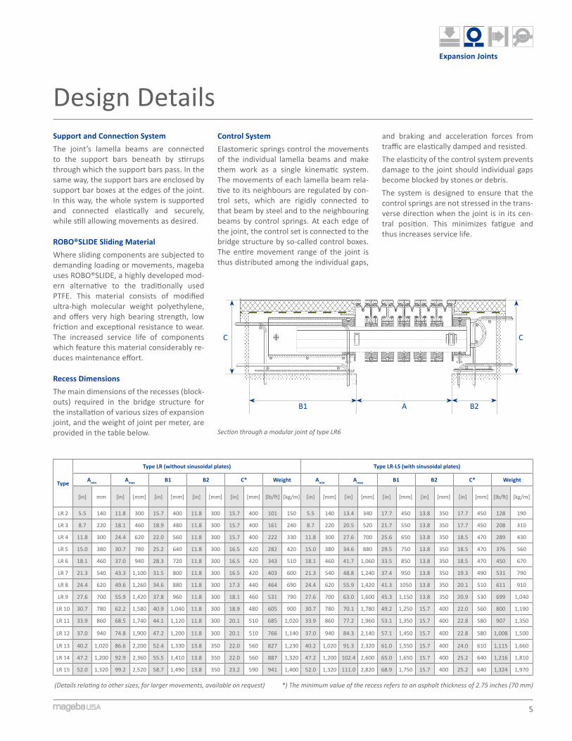
Design DetailsSupport and Connection SystemThe joint’s lamella beams are connected to the support bars beneath by stirrups through which the support bars pass. In the same way, the support bars are enclosed by support bar boxes at the edges of the joint. In this way, the whole system is supported and connected elastically and securely, while still allowing movements as desired.
ROBO®SLIDE Sliding MaterialWhere sliding components are subjected to demanding loading or movements, mageba uses ROBO®SLIDE, a highly developed mod-ern alternative to the traditionally used PTFE. This material consists of modified ultra-high molecular weight polyethylene, and offers very high bearing strength, low friction and exceptional resistance to wear. The increased service life of components which feature this material considerably re-duces maintenance effort.
Recess DimensionsThe main dimensions of the recesses (block-outs) required in the bridge structure for the installation of various sizes of expansion joint, and the weight of joint per meter, are provided in the table below.
Control SystemElastomeric springs control the movements of the individual lamella beams and make them work as a single kinematic system. The movements of each lamella beam rela-tive to its neighbours are regulated by con-trol sets, which are rigidly connected to that beam by steel and to the neighbouring beams by control springs. At each edge of the joint, the control set is connected to the bridge structure by so-called control boxes. The entire movement range of the joint is thus distributed among the individual gaps,
Type
Type LR (without sinusoidal plates) Type LR-LS (with sinusoidal plates)
Amin Amax B1 B2 C* Weight Amin Amax B1 B2 C* Weight
[in] mm [in] [mm] [in] [mm] [in] [mm] [in] [mm] [lb/ft] [kg/m] [in] [mm] [in] [mm] [in] [mm] [in] [mm] [in] [mm] [lb/ft] [kg/m]
LR 2 5.5 140 11.8 300 15.7 400 11.8 300 15.7 400 101 150 5.5 140 13.4 340 17.7 450 13.8 350 17.7 450 128 190
LR 3 8.7 220 18.1 460 18.9 480 11.8 300 15.7 400 161 240 8.7 220 20.5 520 21.7 550 13.8 350 17.7 450 208 310
LR 4 11.8 300 24.4 620 22.0 560 11.8 300 15.7 400 222 330 11.8 300 27.6 700 25.6 650 13.8 350 18.5 470 289 430
LR 5 15.0 380 30.7 780 25.2 640 11.8 300 16.5 420 282 420 15.0 380 34.6 880 29.5 750 13.8 350 18.5 470 376 560
LR 6 18.1 460 37.0 940 28.3 720 11.8 300 16.5 420 343 510 18.1 460 41.7 1,060 33.5 850 13.8 350 18.5 470 450 670
LR 7 21.3 540 43.3 1,100 31.5 800 11.8 300 16.5 420 403 600 21.3 540 48.8 1,240 37.4 950 13.8 350 19.3 490 531 790
LR 8 24.4 620 49.6 1,260 34.6 880 11.8 300 17.3 440 464 690 24.4 620 55.9 1,420 41.3 1050 13.8 350 20.1 510 611 910
LR 9 27.6 700 55.9 1,420 37.8 960 11.8 300 18.1 460 531 790 27.6 700 63.0 1,600 45.3 1,150 13.8 350 20.9 530 699 1,040
LR 10 30.7 780 62.2 1,580 40.9 1,040 11.8 300 18.9 480 605 900 30.7 780 70.1 1,780 49.2 1,250 15.7 400 22.0 560 800 1,190
LR 11 33.9 860 68.5 1,740 44.1 1,120 11.8 300 20.1 510 685 1,020 33.9 860 77.2 1,960 53.1 1,350 15.7 400 22.8 580 907 1,350
LR 12 37.0 940 74.8 1,900 47.2 1,200 11.8 300 20.1 510 766 1,140 37.0 940 84.3 2,140 57.1 1,450 15.7 400 22.8 580 1,008 1,500
LR 13 40.2 1,020 86.6 2,200 52.4 1,330 13.8 350 22.0 560 827 1,230 40.2 1,020 91.3 2,320 61.0 1,550 15.7 400 24.0 610 1,115 1,660
LR 14 47.2 1,200 92.9 2,360 55.5 1,410 13.8 350 22.0 560 887 1,320 47.2 1,200 102.4 2,600 65.0 1,650 15.7 400 25.2 640 1,216 1,810
LR 15 52.0 1,320 99.2 2,520 58.7 1,490 13.8 350 23.2 590 941 1,400 52.0 1,320 111.0 2,820 68.9 1,750 15.7 400 25.2 640 1,324 1,970
(Details relating to other sizes, for larger movements, available on request)
Section through a modular joint of type LR6
and braking and acceleration forces from traffic are elastically damped and resisted.The elasticity of the control system prevents damage to the joint should individual gaps become blocked by stones or debris.The system is designed to ensure that the control springs are not stressed in the trans-verse direction when the joint is in its cen-tral position. This minimizes fatigue and thus increases service life.
*) The minimum value of the recess refers to an asphalt thickness of 2.75 inches (70 mm)
6
4
1
2
3
Expansion Joints
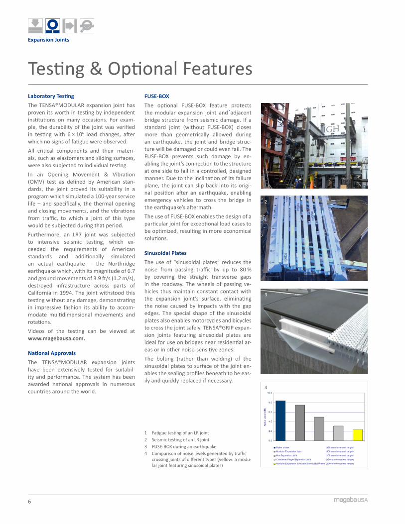
Testing & Optional FeaturesLaboratory TestingThe TENSA®MODULAR expansion joint has proven its worth in testing by independent institutions on many occasions. For exam-ple, the durability of the joint was verified in testing with 6 × 10⁶ load changes, after which no signs of fatigue were observed.All critical components and their materi-als, such as elastomers and sliding surfaces, were also subjected to individual testing.In an Opening Movement & Vibration (OMV) test as defined by American stan-dards, the joint proved its suitability in a program which simulated a 100-year service life – and specifically, the thermal opening and closing movements, and the vibrations from traffic, to which a joint of this type would be subjected during that period.Furthermore, an LR7 joint was subjected to intensive seismic testing, which ex-ceeded the requirements of American standards and additionally simulated an actual earthquake – the Northridge earthquake which, with its magnitude of 6.7 and ground movements of 3.9 ft/s (1.2 m/s), destroyed infrastructure across parts of California in 1994. The joint withstood this testing without any damage, demonstrating in impressive fashion its ability to accom-modate multidimensional movements and rotations. Videos of the testing can be viewed at www.magebausa.com.
National Approvals The TENSA®MODULAR expansion joints have been extensively tested for suitabil-ity and performance. The system has been awarded national approvals in numerous countries around the world.
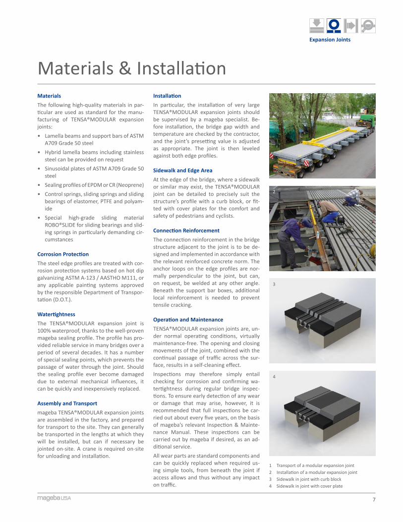
1 Fatigue testing of an LR joint2 Seismic testing of an LR joint3 FUSE-BOX during an earthquake4 Comparison of noise levels generated by traffic
crossing joints of different types (yellow: a modu-lar joint featuring sinusoidal plates)
FUSE-BOX The optional FUSE-BOX feature protects the modular expansion joint and adjacent bridge structure from seismic damage. If a standard joint (without FUSE-BOX) closes more than geometrically allowed during an earthquake, the joint and bridge struc-ture will be damaged or could even fail. The FUSE-BOX prevents such damage by en-abling the joint’s connection to the structure at one side to fail in a controlled, designed manner. Due to the inclination of its failure plane, the joint can slip back into its origi-nal position after an earthquake, enabling emergency vehicles to cross the bridge in the earthquake’s aftermath.The use of FUSE-BOX enables the design of a particular joint for exceptional load cases to be optimized, resulting in more economical solutions.
Sinusoidal PlatesThe use of “sinusoidal plates” reduces the noise from passing traffic by up to 80 % by covering the straight transverse gaps in the roadway. The wheels of passing ve-hicles thus maintain constant contact with the expansion joint’s surface, eliminating the noise caused by impacts with the gap edges. The special shape of the sinusoidal plates also enables motorcycles and bicycles to cross the joint safely. TENSA®GRIP expan-sion joints featuring sinusoidal plates are ideal for use on bridges near residential ar-eas or in other noise-sensitive zones.The bolting (rather than welding) of the sinusoidal plates to surface of the joint en-ables the sealing profiles beneath to be eas-ily and quickly replaced if necessary.
Roller shuter (450 mm movement range)
Modular Expansion Joint (400 mm movement range)
Mat Expansion Joint (100 mm movement range)
Cantilever Finger Expansion Joint (150 mm movement range)
Modular Expansion Joint with Sinusoidal Plates (400 mm movement range)
7
2
1
3
4
Expansion Joints
Materials & Installation
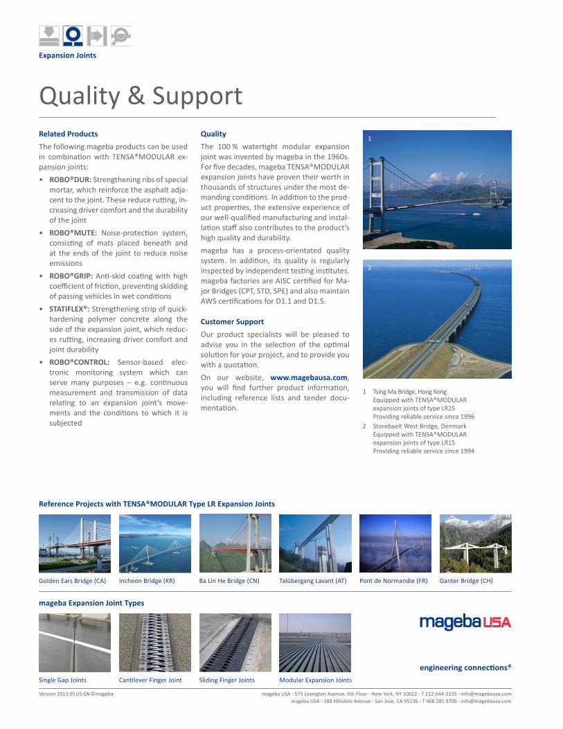
1 Transport of a modular expansion joint2 Installation of a modular expansion joint3 Sidewalk in joint with curb block4 Sidewalk in joint with cover plate
MaterialsThe following high-quality materials in par-ticular are used as standard for the manu-facturing of TENSA®MODULAR expansion joints:• Lamella beams and support bars of ASTM
A709 Grade 50 steel• Hybrid lamella beams including stainless
steel can be provided on request• Sinusoidal plates of ASTM A709 Grade 50
steel• Sealing profiles of EPDM or CR (Neoprene)• Control springs, sliding springs and sliding
bearings of elastomer, PTFE and polyam-ide
• Special high-grade sliding material ROBO®SLIDE for sliding bearings and slid-ing springs in particularly demanding cir-cumstances
Corrosion ProtectionThe steel edge profiles are treated with cor-rosion protection systems based on hot dip galvanizing ASTM A-123 / AASTHO M111, or any applicable painting systems approved by the responsible Department of Transpor-tation (D.O.T.).
WatertightnessThe TENSA®MODULAR expansion joint is 100% waterproof, thanks to the well-proven mageba sealing profile. The profile has pro-vided reliable service in many bridges over a period of several decades. It has a number of special sealing points, which prevents the passage of water through the joint. Should the sealing profile ever become damaged due to external mechanical influences, it can be quickly and inexpensively replaced.
Assembly and Transportmageba TENSA®MODULAR expansion joints are assembled in the factory, and prepared for transport to the site. They can generally be transported in the lengths at which they will be installed, but can if necessary be jointed on-site. A crane is required on-site for unloading and installation.
InstallationIn particular, the installation of very large TENSA®MODULAR expansion joints should be supervised by a mageba specialist. Be-fore installation, the bridge gap width and temperature are checked by the contractor, and the joint’s presetting value is adjusted as appropriate. The joint is then leveled against both edge profiles.
Sidewalk and Edge Area At the edge of the bridge, where a sidewalk or similar may exist, the TENSA®MODULAR joint can be detailed to precisely suit the structure’s profile with a curb block, or fit-ted with cover plates for the comfort and safety of pedestrians and cyclists.
Connection ReinforcementThe connection reinforcement in the bridge structure adjacent to the joint is to be de-signed and implemented in accordance with the relevant reinforced concrete norm. The anchor loops on the edge profiles are nor-mally perpendicular to the joint, but can, on request, be welded at any other angle. Beneath the support bar boxes, additional local reinforcement is needed to prevent tensile cracking.
Operation and MaintenanceTENSA®MODULAR expansion joints are, un-der normal operating conditions, virtually maintenance-free. The opening and closing movements of the joint, combined with the continual passage of traffic across the sur-face, results in a self-cleaning effect.Inspections may therefore simply entail checking for corrosion and confirming wa-tertightness during regular bridge inspec-tions. To ensure early detection of any wear or damage that may arise, however, it is recommended that full inspections be car-ried out about every five years, on the basis of mageba’s relevant Inspection & Mainte-nance Manual. These inspections can be carried out by mageba if desired, as an ad-ditional service.All wear parts are standard components and can be quickly replaced when required us-ing simple tools, from beneath the joint if access allows and thus without any impact on traffic.
1
2
Expansion Joints
Quality & SupportRelated ProductsThe following mageba products can be used in combination with TENSA®MODULAR ex-pansion joints:• ROBO®DUR: Strengthening ribs of special
mortar, which reinforce the asphalt adja-cent to the joint. These reduce rutting, in-creasing driver comfort and the durability of the joint
• ROBO®MUTE: Noise-protection system, consisting of mats placed beneath and at the ends of the joint to reduce noise emissions
• ROBO®GRIP: Anti-skid coating with high coefficient of friction, preventing skidding of passing vehicles in wet conditions
• STATIFLEX®: Strengthening strip of quick-hardening polymer concrete along the side of the expansion joint, which reduc-es rutting, increasing driver comfort and joint durability
• ROBO®CONTROL: Sensor-based elec-tronic monitoring system which can serve many purposes – e.g. continuous measurement and transmission of data relating to an expansion joint’s move-ments and the conditions to which it is subjected
QualityThe 100 % watertight modular expansion joint was invented by mageba in the 1960s. For five decades, mageba TENSA®MODULAR expansion joints have proven their worth in thousands of structures under the most de-manding conditions. In addition to the prod-uct properties, the extensive experience of our well-qualified manufacturing and instal-lation staff also contributes to the product’s high quality and durability.mageba has a process-orientated quality system. In addition, its quality is regularly inspected by independent testing institutes. mageba factories are AISC certified for Ma-jor Bridges (CPT, STD, SPE) and also maintain AWS certifications for D1.1 and D1.5.
Customer SupportOur product specialists will be pleased to advise you in the selection of the optimal solution for your project, and to provide you with a quotation.On our website, www.magebausa.com, you will find further product information, including reference lists and tender docu-mentation.
Reference Projects with TENSA®MODULAR Type LR Expansion Joints
mageba Expansion Joint Types
1 Tsing Ma Bridge, Hong Kong Equipped with TENSA®MODULAR expansion joints of type LR25 Providing reliable service since 1996
2 Storebaelt West Bridge, Denmark Equipped with TENSA®MODULAR expansion joints of type LR15 Providing reliable service since 1994
Golden Ears Bridge (CA) Incheon Bridge (KR) Ba Lin He Bridge (CN) Talübergang Lavant (AT) Ganter Bridge (CH)Pont de Normandie (FR)
Sliding Finger JointsCantilever Finger JointSingle Gap Joints Modular Expansion Joints
mageba USA - 575 Lexington Avenue, 4th Floor - New York, NY 10022 - T 212-644-3335 - [email protected] USA - 188 Hillsdale Avenue - San Jose, CA 95136 - T 408 281 9700 - [email protected]
Version 2013.05 US-EN ©mageba