expanded by jozef goetz, 2009 the mcgraw-hill companies, inc., 2006
DESCRIPTION
Chapter 3 Signals. PART III. expanded by Jozef Goetz, 2009 The McGraw-Hill Companies, Inc., 2006. expanded by Jozef Goetz, 2009. 3.4 Transmission Imp a irment. Att e nuation Dist o rtion Noise. Figure 3.25 Imp a irment types. Att e nuation = means loss of energy. - PowerPoint PPT PresentationTRANSCRIPT

Jozef Goetz, 2009
1
expanded by Jozef Goetz, 2009
The McGraw-Hill Companies, Inc., 2006
expanded by Jozef Goetz, 2009
PART IIIPART III
Jozef Goetz, 2009
2
3.4 Transmission Imp3.4 Transmission Impaairmentirment
Attenuation
Distortion
Noise
Jozef Goetz, 2009
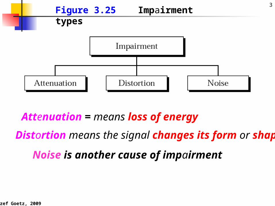
3Figure 3.25 Impairment types
Distortion means the signal changes its form or shape
Attenuation = means loss of energy
Noise is another cause of impairment
Jozef Goetz, 2009
4
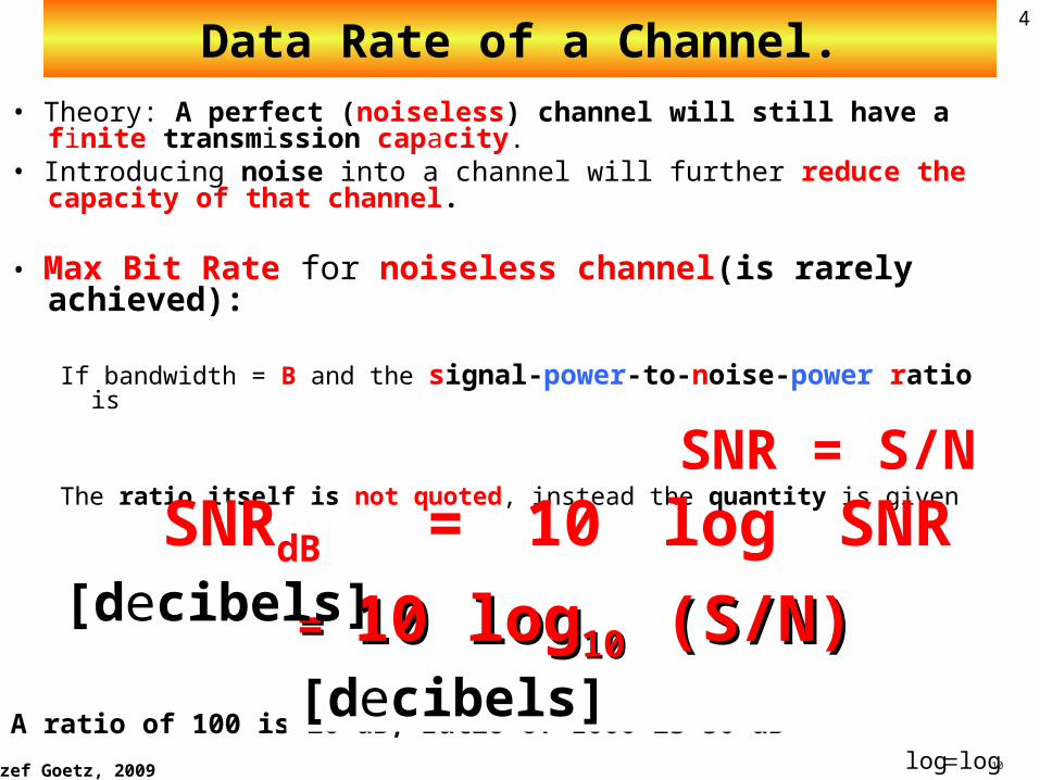
Data Rate of a Channel.• Theory: A perfect (noiseless) channel will still have a finite
transmission capacity.• Introducing noise into a channel will further reduce the
capacity of that channel.
• Max Bit Rate for noiseless channel(is rarely achieved):
If bandwidth = B and the signal-power-to-noise-power ratio is
SNR = S/NThe ratio itself is not quoted, instead the quantity is given
A ratio of 100 is 20 dB, ratio of 1000 is 30 dB 10loglog
= = 10 log10 log1010 (S/N) (S/N) [decibels]
SNRdB = 10 log SNR [decibels]
Jozef Goetz, 2009
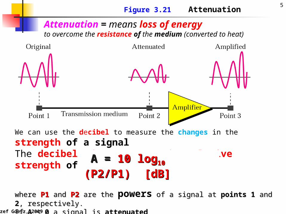
5 Figure 3.21 Attenuation
We can use the decibel to measure the changes in the strength of a signal
The decibel (dB) measures the relative strength of 2 signals
where where P1P1 and and P2P2 are the are the powers of a signal at of a signal at points 1points 1 and and 22, respectively., respectively.If If A < 0A < 0 a signal is a signal is attenuatedattenuatedIf If A > 0A > 0 a signal is a signal is amplifiedamplified
A = A = 10 log10 log1010 (P2/P1) [dB] (P2/P1) [dB]
Attenuation = means loss of energy to overcome the resistance of the medium (converted to heat)
Jozef Goetz, 2009
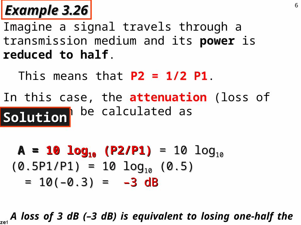
6Example 3.26Example 3.26
Imagine a signal travels through a transmission medium and its power is reduced to half.
This means that P2 = 1/2 P1.
In this case, the attenuation (loss of power) can be calculated as
SolutionSolution
A = A = 10 log10 log1010 (P2/P1) (P2/P1) = 10 log= 10 log1010 (0.5P1/P1) = 10 log (0.5P1/P1) = 10 log1010 (0.5) (0.5)
= 10(–0.3) = = 10(–0.3) = –3 dB –3 dB
A loss of 3 dB (–3 dB) is equivalent to losing one-half the power.
Jozef Goetz, 2009
7
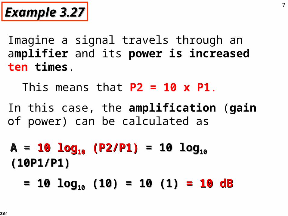
Example 3.27Example 3.27
Imagine a signal travels through an amplifier and its power is increased ten times.
This means that P2 = 10 x P1.
In this case, the amplification (gain of power) can be calculated as
AA = = 10 log10 log1010 (P2/P1) (P2/P1) = 10 log= 10 log1010 (10P1/P1) (10P1/P1)
= 10 log= 10 log1010 (10) = 10 (1) (10) = 10 (1) = 10 dB = 10 dB
What is A when its power is increased 2 times?What is A when its power is increased 2 times?
Jozef Goetz, 2009
8
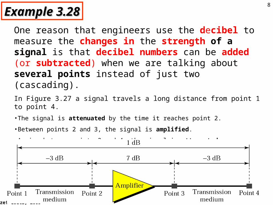
Example 3.28Example 3.28
One reason that engineers use the decibel to measure the changes in the strength of a signal is that decibel numbers can be added (or subtracted) when we are talking about several points instead of just two (cascading).
In Figure 3.27 a signal travels a long distance from point 1 to point 4.
•The signal is attenuated by the time it reaches point 2.
•Between points 2 and 3, the signal is amplified.
•Again, between points 3 and 4, the signal is attenuated.
•We can find the resultant decibel for the signal just by adding the decibel measurements between each set of points.
Jozef Goetz, 2009
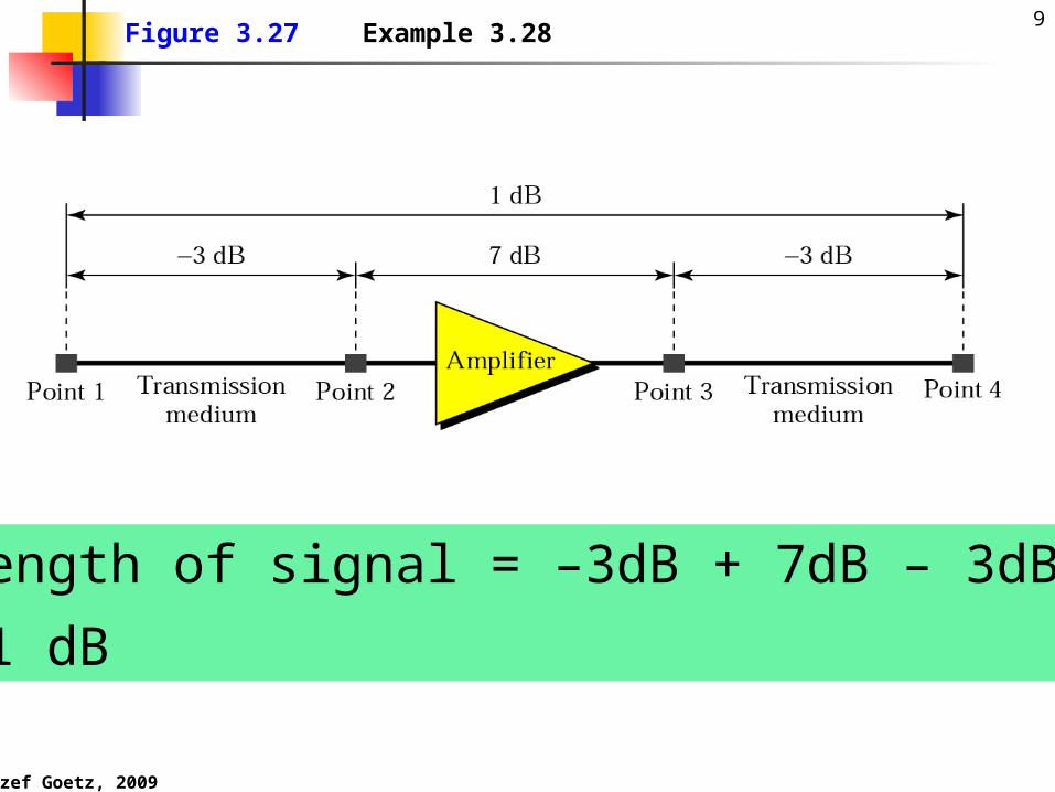
9Figure 3.27 Example 3.28
strength of signal = –3dB + 7dB – 3dB
= +1 dB
Jozef Goetz, 2009
10
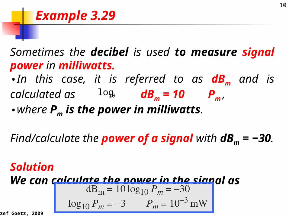
Sometimes the decibel is used to measure signal power in milliwatts. •In this case, it is referred to as dBm and is calculated as
dBm = 10 Pm , •where Pm is the power in milliwatts.
Find/calculate the power of a signal with dBm = −30.
SolutionWe can calculate the power in the signal as
Example 3.29
10log

Jozef Goetz, 2009
11
The loss in a cable is usually defined in decibels per kilometer (dB/km). If the signal at the beginning of a cable with −0.3 dB/km has a power of 2 mW, what is the power of the signal at 5 km?SolutionThe loss in the cable in decibels is 5 × (−0.3) = −1.5 dB. We can calculate the power as
Example 3.30
dBXXXXXX
Jozef Goetz, 2009
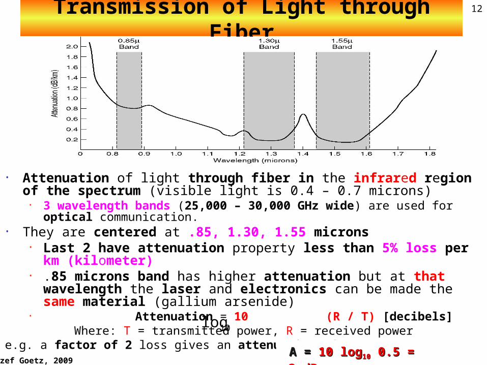
12Transmission of Light through Fiber
• Attenuation of light through fiber in the infrared region of the spectrum (visible light is 0.4 – 0.7 microns)
• 3 wavelength bands (25,000 – 30,000 GHz wide) are used for optical communication.
• They are centered at .85, 1.30, 1.55 microns• Last 2 have attenuation property less than 5% loss per
km (kilometer)• .85 microns band has higher attenuation but at that
wavelength the laser and electronics can be made the same material (gallium arsenide)
• Attenuation = 10 (R / T) [decibels]Where: T = transmitted power, R = received power
e.g. a factor of 2 loss gives an attenuation of A = A = 10 log10 log1010 0.5 = -3 dB 0.5 = -3 dB
10log

Jozef Goetz, 2009
13Figure 3.28 Distortion
Distortion means the signal changes its form or shape.
Each signal has its own propagation speed through a medium,so its own delay
Jozef Goetz, 2009
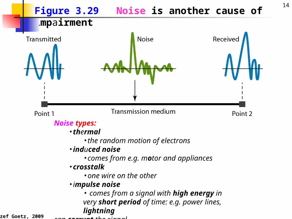
14Figure 3.29 Noise is another cause of impairment
Noise types: •thermal
•the random motion of electrons •induced noise
•comes from e.g. motor and appliances•crosstalk
•one wire on the other•impulse noise
• comes from a signal with high energy in very short period of time: e.g. power lines, lightning
can corrupt the signal.
Jozef Goetz, 2009
15
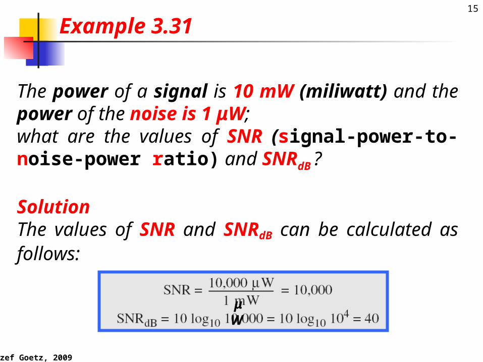
The power of a signal is 10 mW (miliwatt) and the power of the noise is 1 μW; what are the values of SNR (signal-power-to-noise-power ratio) and SNRdB ?
Solution The values of SNR and SNRdB can be calculated as follows:
Example 3.31
μW
Jozef Goetz, 2009
16
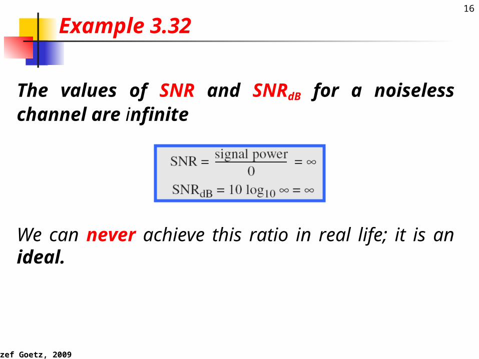
The values of SNR and SNRdB for a noiseless channel are infinite
Example 3.32
We can never achieve this ratio in real life; it is an ideal.
Jozef Goetz, 2009
17
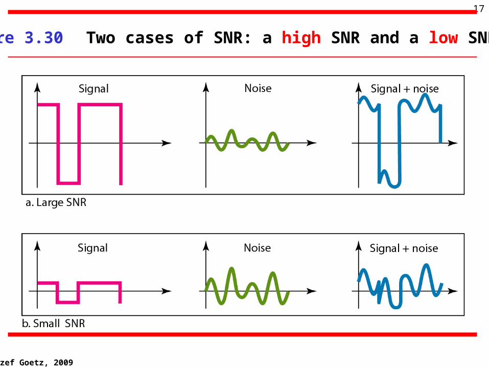
Figure 3.30 Two cases of SNR: a high SNR and a low SNR
Jozef Goetz, 2009
18
3.5 Data Rate Limits3.5 Data Rate Limits
Noiseless Channel: Nyquist Bit Rate
Noisy Channel: Shannon Capacity
Using Both Limits
Jozef Goetz, 2009
19
3.5 Data Rate Limits3.5 Data Rate Limits
Data Rate depends on 3 factors:1.The bandwidth available2.The levels of signals we can use3.The quality (level of the noise) of the channel
A very important consideration in data A very important consideration in data communications is communications is how fast we can send datahow fast we can send data, , inin bits per secondbits per second, over a channel. , over a channel.
Jozef Goetz, 2009
20
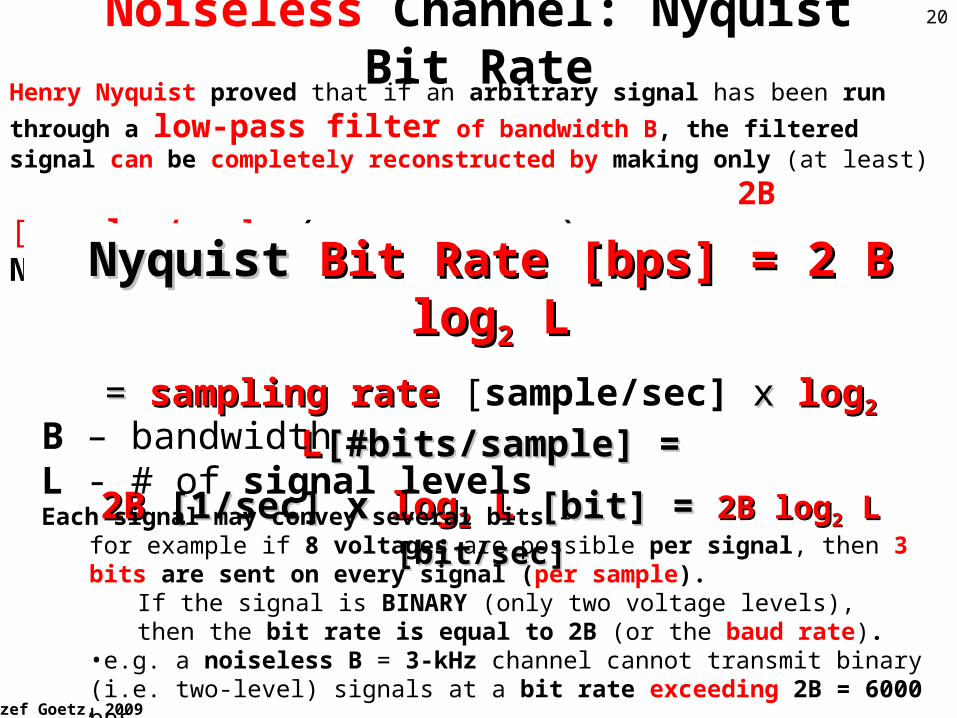
Henry Nyquist proved that if an arbitrary signal has been run through a low-pass filter of bandwidth B, the filtered signal can be completely reconstructed by making only (at least)
2B [samples/sec] (data encoded rate)Nyquist theoretical maximum bit rate:
NyquistNyquist BitBit RateRate [bps] [bps] = 2 = 2 BB log log22 LL
= = sampling rate sampling rate [sample/sec] x x loglog22 LL[#bits/sample] =[#bits/sample] =
2B2B [1/sec] x [1/sec] x loglog22 L L [bit][bit] = = 2B2B loglog22 L L [bit/sec][bit/sec]
Noiseless Channel: Nyquist Bit Rate
B – bandwidthL - # of signal levelsEach signal may convey several bits –
for example if 8 voltages are possible per signal, then 3 bits are sent on every signal (per sample).
If the signal is BINARY (only two voltage levels), then the bit rate is equal to 2B (or the baud rate).
•e.g. a noiseless B = 3-kHz channel cannot transmit binary (i.e. two-level) signals at a bit rate exceeding 2B = 6000 bps.
Jozef Goetz, 2009
21
Increasing the levels of a signal L may reduce the reliability of the system
•b/c it is very unreliable to distinguish signals for high value of L e.g. 64 by the receiver
Note
Jozef Goetz, 2009
22
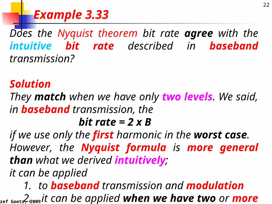
Does the Nyquist theorem bit rate agree with the intuitive bit rate described in baseband transmission?
SolutionThey match when we have only two levels. We said, in baseband transmission, the bit rate = 2 x B if we use only the first harmonic in the worst case. However, the Nyquist formula is more general than what we derived intuitively; it can be applied
1. to baseband transmission and modulation2. it can be applied when we have two or more levels
of signals.
Example 3.33

Jozef Goetz, 2009
23
Example 3.34Example 3.34
Consider a noiseless channel with a bandwidth of 3000 Hz transmitting a signal with two signal levels.
The maximum bit rate can be calculated as
BitBit RateRate = 2 = 2 3000 3000[1/sec][1/sec] log log22 2 2 [bit] [bit] = = 6000 6000 [[bpsbps]]
BitBit RateRate [bps] [bps] = 2 = 2 BB log log22 LL

Jozef Goetz, 2009
24
Example 3.35Example 3.35
Consider the same noiseless channel, transmitting a signal with 4 signal levels (for each level, we send 2 bits). The maximum bit rate can be calculated as:
Bit Rate = Bit Rate = 2 x 3000 [1/sec] x log2 x 3000 [1/sec] x log22 4 [bit]= 4 [bit]= 12,000 [bps]12,000 [bps]
BitBit RateRate [bps] [bps] = 2 = 2 BB log log22 LL
Jozef Goetz, 2009
25
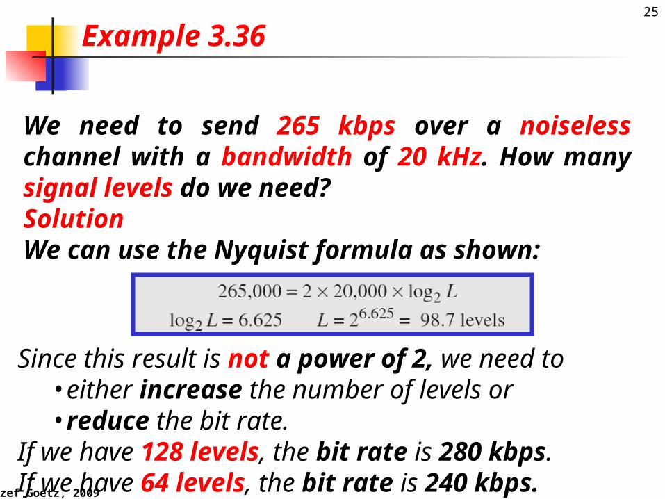
We need to send 265 kbps over a noiseless channel with a bandwidth of 20 kHz. How many signal levels do we need?SolutionWe can use the Nyquist formula as shown:
Example 3.36
Since this result is not a power of 2, we need to •either increase the number of levels or •reduce the bit rate.
If we have 128 levels, the bit rate is 280 kbps. If we have 64 levels, the bit rate is 240 kbps.

Jozef Goetz, 2009
26Noisy Channel: Shannon Capacity
Theory: A perfect (noiseless) channel will still have a finite transmission capacity.
• Introducing noise (thermal or white noise) into a channel will further reduce the capacity of that channel.
Theoretical maximum data rate for a noisy channel = Capacity C
SNR - signal-to-noise ratio
the formula defines characteristic of the channel, not the method of transmission b/c there is no indication of the signal level
• E.g. a channel of B = 3000 Hz bandwidth with the a signal to thermal noise ratio of 3162 dB (typical for analog tel. system) can never transmit much more than 30,000 bps
• No matter how many or how few signal levels are used and• No matter how often or how infrequently samples are taken
C C [bps][bps] = B log= B log22 (1 + SNR) (1 + SNR)

Jozef Goetz, 2009
27
Example 3.37Example 3.37
Consider an extremely noisy channel in which the value of the signal-to-noise ratio is almost zero.
In other words, the noise is so strong that the signal is faint. For this channel the capacity is calculated as
C C [bps][bps] = B log= B log22 (1 + SNR) (1 + SNR) == B logB log22 (1 + 0) (1 + 0)
= B log= B log22 (1) = B (1) = B 0 0 == 0 0
Jozef Goetz, 2009
28
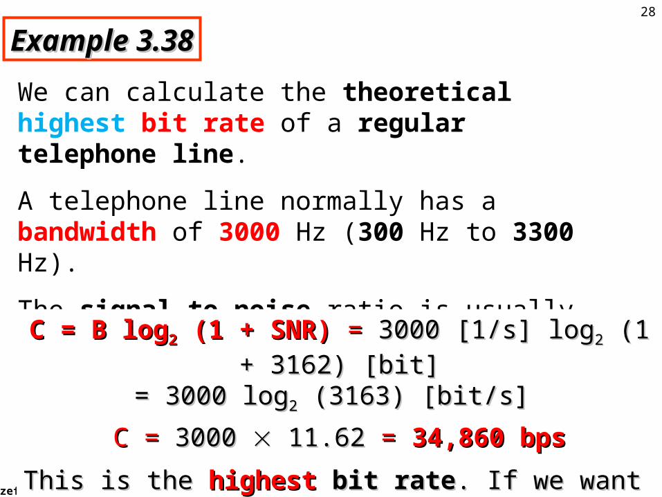
Example 3.38Example 3.38
We can calculate the theoretical highest bit rate of a regular telephone line.
A telephone line normally has a bandwidth of 3000 Hz (300 Hz to 3300 Hz).
The signal-to-noise ratio is usually 3162. For this channel the capacity is calculated as
C = B logC = B log22 (1 + SNR) (1 + SNR) = = 3000 [1/s] log3000 [1/s] log22 (1 + 3162) [bit] (1 + 3162) [bit]
= 3000 log= 3000 log22 (3163) [bit/s] (3163) [bit/s]
C = C = 3000 3000 11.62 11.62 = = 34,860 bps34,860 bps
This is the This is the highesthighest bit rate bit rate. If we want to send faster than . If we want to send faster than this, we can either increase this, we can either increase BB or or SNRSNR
Jozef Goetz, 2009
29
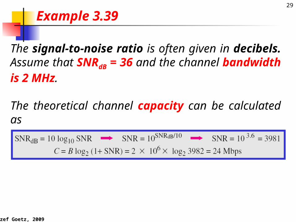
The signal-to-noise ratio is often given in decibels. Assume that SNRdB = 36 and the channel bandwidth is 2 MHz.
The theoretical channel capacity can be calculated as
Example 3.39
Jozef Goetz, 2009
30
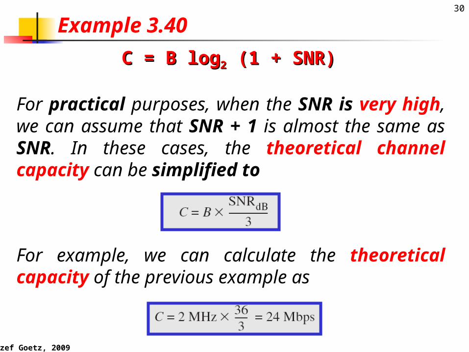
For practical purposes, when the SNR is very high, we can assume that SNR + 1 is almost the same as SNR. In these cases, the theoretical channel capacity can be simplified to
Example 3.40
For example, we can calculate the theoretical capacity of the previous example as
C = B logC = B log22 (1 + SNR) (1 + SNR)
Jozef Goetz, 2009
31
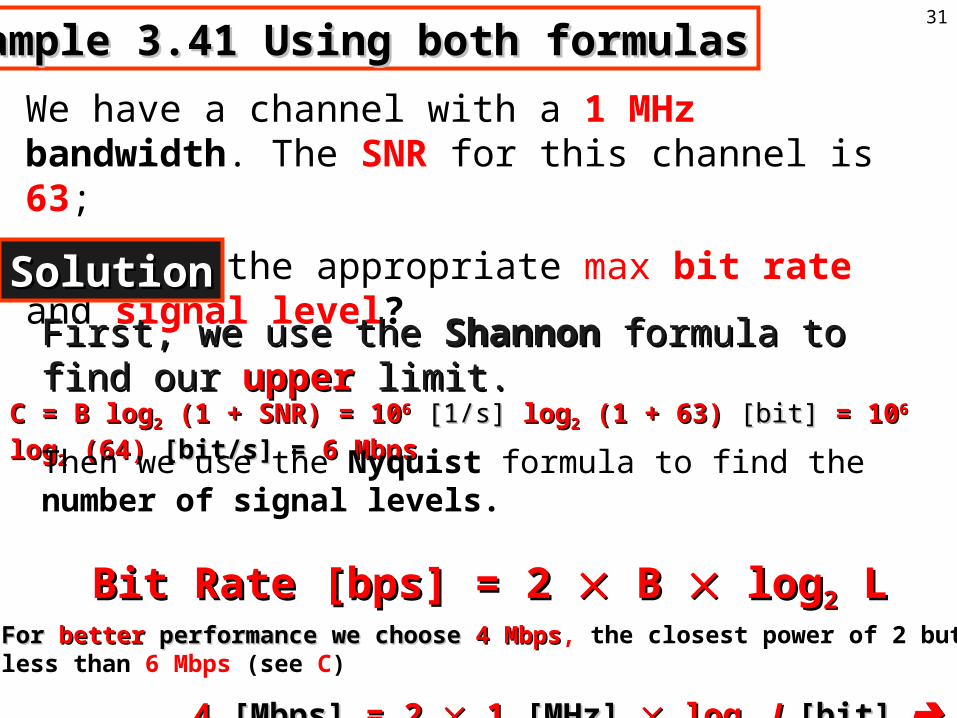
Example 3.41 Using both formulasExample 3.41 Using both formulas
We have a channel with a 1 MHz bandwidth. The SNR for this channel is 63;
•what is the appropriate max bit rate and signal level?
SolutionSolution
C = B logC = B log22 (1 + SNR) = 10 (1 + SNR) = 1066 [1/s] [1/s] loglog22 (1 + 63) (1 + 63) [bit] [bit] = 10= 1066 log log22 (64) (64) [bit/s] = [bit/s] = 6 Mbps6 Mbps
Then we use the Nyquist formula to find the number of signal levels.
For For betterbetter performance we choose performance we choose 4 Mbps4 Mbps, the closest power of 2 but less than 6 Mbps (see C)
4 4 [[MbpsMbps]] = 2 = 2 1 1 [[MHzMHz]] log log22 LL [bit][bit] L = 4 L = 4
First, we use the First, we use the ShannonShannon formula to find our formula to find our upperupper limit.limit.
BitBit RateRate [bps] [bps] = 2 = 2 BB log log22 LL
Jozef Goetz, 2009
32
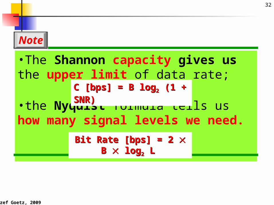
•The Shannon capacity gives us the upper limit of data rate;
•the Nyquist formula tells us how many signal levels we need.
Note
BitBit RateRate [bps] [bps] = 2 = 2 BB log log22
LL
C C [bps][bps] = B log= B log22 (1 + SNR) (1 + SNR)

Jozef Goetz, 2009
33
3-6 PERFORMANCE3-6 PERFORMANCE
•One important issue in networking is the One important issue in networking is the performanceperformance of of the network—how good is it? the network—how good is it? •We discuss We discuss quality of servicequality of service, an , an overall measurement overall measurement of network performanceof network performance, in greater detail in Chapter 24. , in greater detail in Chapter 24. •In this section, we introduce terms that we need for future In this section, we introduce terms that we need for future chapters.chapters.
BandwidthThroughputLatency (Delay)Bandwidth-Delay Product
Topics discussed in this section:Topics discussed in this section:
Jozef Goetz, 2009
34
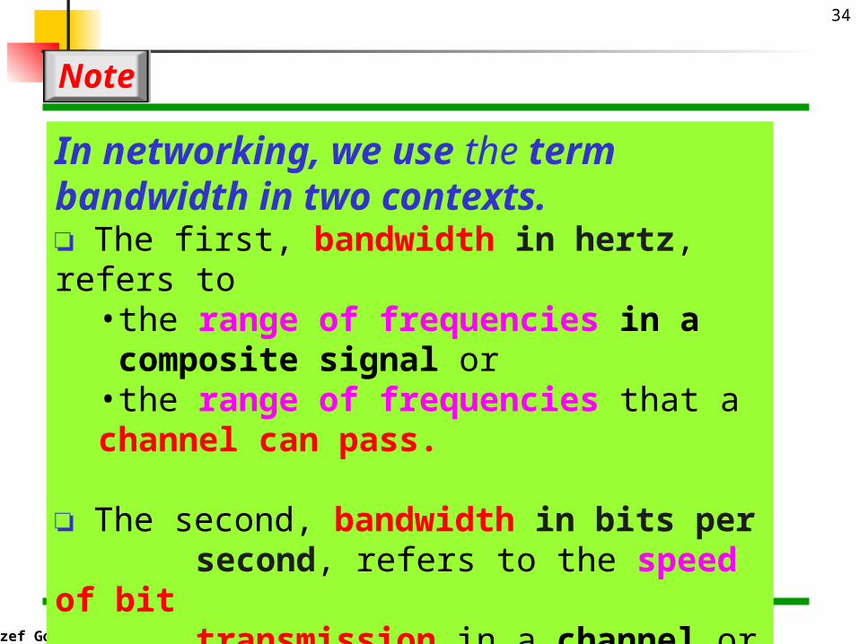
In networking, we use the term bandwidth in two contexts.❏ The first, bandwidth in hertz, refers to
•the range of frequencies in a composite signal or •the range of frequencies that a channel can pass.
❏ The second, bandwidth in bits per second, refers to the speed of bit transmission in a channel or link.
Note
Jozef Goetz, 2009
35
An increase in bandwidth in hertz means an increase in bandwidth in bits/second
Note
Jozef Goetz, 2009
36
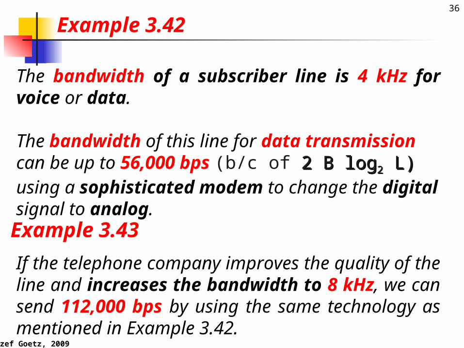
The bandwidth of a subscriber line is 4 kHz for voice or data.
The bandwidth of this line for data transmissioncan be up to 56,000 bps (b/c of 2 2 BB log log22 L) L) using a sophisticated modem to change the digital signal to analog.
Example 3.42
If the telephone company improves the quality of the line and increases the bandwidth to 8 kHz, we can send 112,000 bps by using the same technology as mentioned in Example 3.42.
Example 3.43
Jozef Goetz, 2009
37Throughput
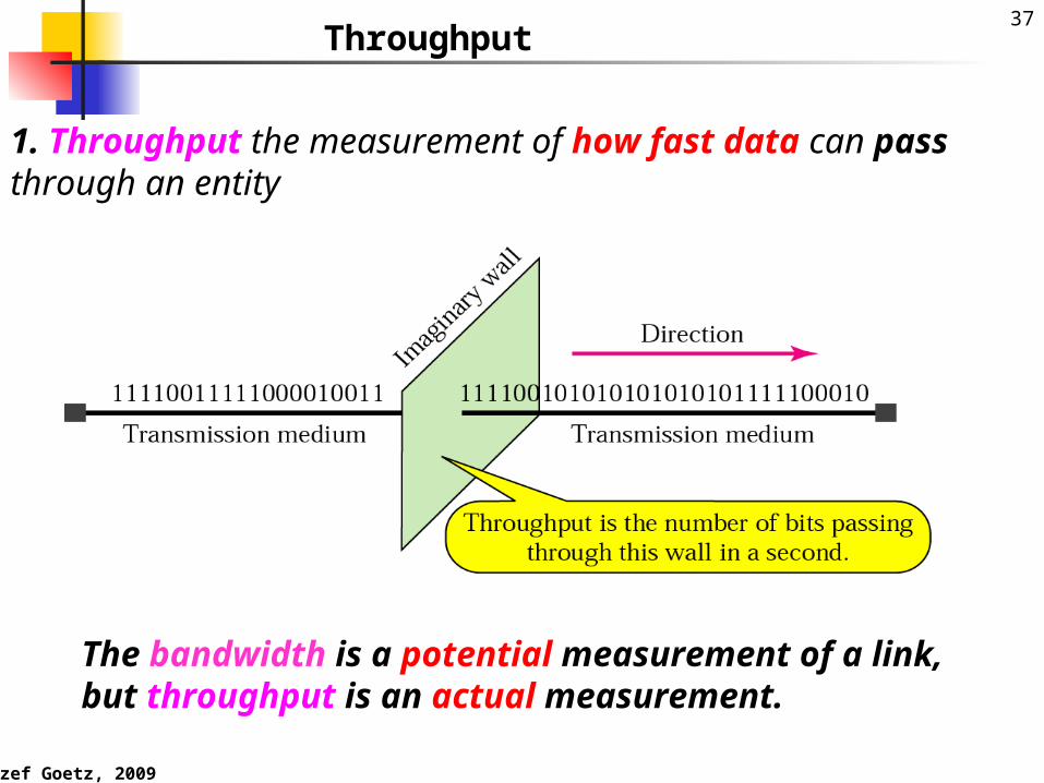
1. Throughput the measurement of how fast data can pass through an entity
The bandwidth is a potential measurement of a link, but throughput is an actual measurement.
Jozef Goetz, 2009
38
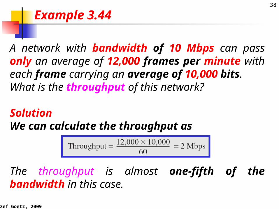
A network with bandwidth of 10 Mbps can pass only an average of 12,000 frames per minute with each frame carrying an average of 10,000 bits. What is the throughput of this network?
SolutionWe can calculate the throughput as
Example 3.44
The throughput is almost one-fifth of the bandwidth in this case.
Jozef Goetz, 2009
39Propagation
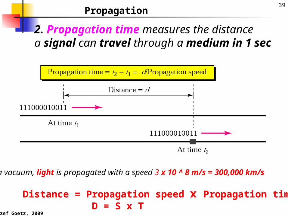
2. Propagation time measures the distance a signal can travel through a medium in 1 sec
In a vacuum, light is propagated with a speed 3 x 10 ^ 8 m/s = 300,000 km/s
Distance = Propagation speed x Propagation time D = S x T
Jozef Goetz, 2009
40
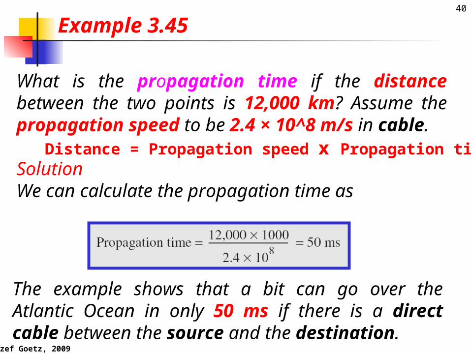
What is the propagation time if the distance between the two points is 12,000 km? Assume the propagation speed to be 2.4 × 10^8 m/s in cable.
SolutionWe can calculate the propagation time as
Example 3.45
The example shows that a bit can go over the Atlantic Ocean in only 50 ms if there is a direct cable between the source and the destination.
Distance = Propagation speed x Propagation time

Jozef Goetz, 2009
41
Transmission time3. Transmission time measures the time required for transmission of a message•A time between the first bit leaving the sender and the last bit arriving at the receiver.
Transmission time = Message size / Bandwidth or Message size = Bandwidth x Transmission timeIn a vacuum, light is propagated with a speed 3 x 10 ^ 8 m/s = 300,000 km/s
Jozef Goetz, 2009
42
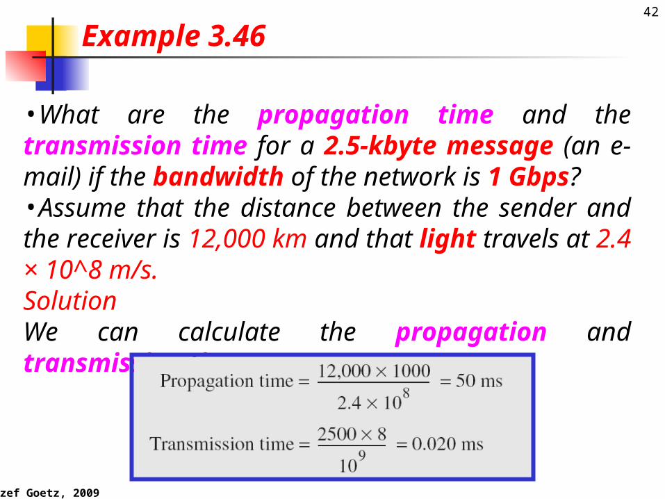
•What are the propagation time and the transmission time for a 2.5-kbyte message (an e-mail) if the bandwidth of the network is 1 Gbps? •Assume that the distance between the sender and the receiver is 12,000 km and that light travels at 2.4 × 10^8 m/s.SolutionWe can calculate the propagation and transmission time
Example 3.46
Jozef Goetz, 2009
43
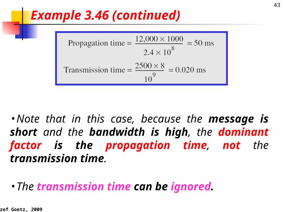
•Note that in this case, because the message is short and the bandwidth is high, the dominant factor is the propagation time, not the transmission time.
•The transmission time can be ignored.
Example 3.46 (continued)

Jozef Goetz, 2009
44
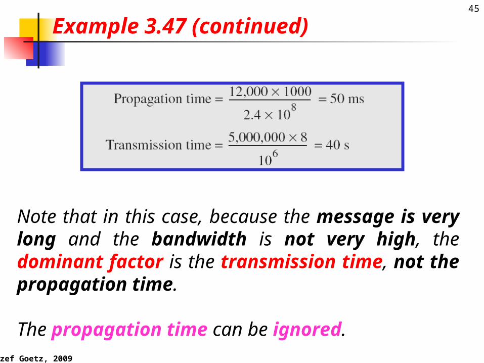
What are the propagation time and the transmission time for a 5-Mbyte message (an image) if the bandwidth of the network is 1 Mbps? •Assume that the distance between the sender and the receiver is 12,000 km and that light travels at 2.4 × 10⁸ m/s.
Solution
Example 3.47
Jozef Goetz, 2009
45
Note that in this case, because the message is very long and the bandwidth is not very high, the dominant factor is the transmission time, not the propagation time.
The propagation time can be ignored.
Example 3.47 (continued)
Jozef Goetz, 2009
46
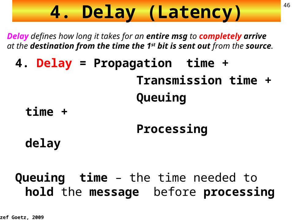
4. Delay (Latency)
4. Delay = Propagation time + Transmission time + Queuing time + Processing delay
Queuing time – the time needed to hold the message before processing
Delay defines how long it takes for an entire msg to completely arrive at the destination from the time the 1st bit is sent out from the source.

Jozef Goetz, 2009
47
Figure 3.31 Filling the link with bits for case 1
Delay defines how long it takes for an entire msg to completely arrive at the destination from the time the 1st bit is sent out from the source.
Product 1 x 5 is the maximum bits can fill the link.
Jozef Goetz, 2009
48
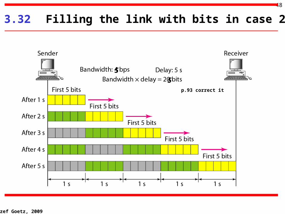
Figure 3.32 Filling the link with bits in case 2
5
5p.93 correct it
Jozef Goetz, 2009
49
5. The bandwidth-delay product defines the number of bits that can fill the link.
Note

Jozef Goetz, 2009
50
We can think about the link between two points as a pipe.
The cross section of the pipe represents the bandwidth, and the length of the pipe represents the delay.
We can say the volume of the pipe defines the
bandwidth-delay product, as shown in Figure 3.33.
Concept of bandwidth-delay product
Jozef Goetz, 2009
51
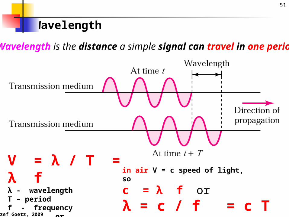
Wavelength
Wavelength is the distance a simple signal can travel in one period
V = λ / T = λ fλ - wavelength T – periodf - frequency or
T = λ/V
in air V = c speed of light, so
c = λ f or
λ = c / f = c T

Jozef Goetz, 2009
52 WavelengthWavelength λ binds the period T (or the frequency f ) of a simple sine wave to the propagation speed V of the medium.The frequency of a signal is independent of the medium the wavelength depends on both the frequency and the medium:
λ = c / f = c T
V = λ / T = λ fλ - wavelength T – periodf - frequency
in air V = c speed of light, so
c = λ f or
λ = c / f = c T

Jozef Goetz, 2009
53
Summary
The physical layer is responsible for transmitting a bit stream over a physical
medium. It is concerned witha. physical characteristics of the mediab. representation of bitsc. type of encodingd. synchronization of bitse. transmission rate and modef. the way devices are connected with
each other and to the links

Jozef Goetz, 2009
54
Analog = continuous
Digital = discrete
ANALOG AND DIGITAL DATA TRANSMISSION SUMMARY
Data - entities that convey meaning, or informationSignals - are electromagnetic representations of data.Signaling - is the physical propagation of signal along a suitable medium.
Transmission - communication of data by the propagation and processing of signals.
Jozef Goetz, 2009
55
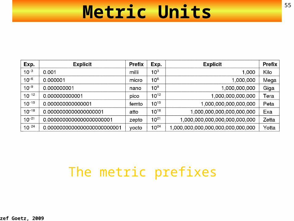
Metric Units
The metric prefixes

Jozef Goetz, 2009
56Analog and Digital Signals: Summary
•Signals are means by which data is propagated•Analog
• Continuously variable• Various media
• wire, fiber optic, • Speech bandwidth 100Hz to 7kHz• Telephone bandwidth 300Hz to 3400Hz• Video bandwidth 4MHz
Digital
Jozef Goetz, 2009
57
Summary
* Data must be transformed into electromagnetic signals prior to transmission across a network.
* Data and signals can be either analog or digital. * A signal is periodic if it consists of a continuously
repeating pattern. * Each sine wave can be characterized by its
amplitude, frequency, and phase. * Frequency and period are inverses of each other. * A time-domain graph plots amplitude as a
function of time. * A frequency-domain graph plots each sine
wave’s peak amplitude against its frequency. * By using Fourier analysis, any composite signal
can be represented as a combination of simple sine waves.
Jozef Goetz, 2009
58
Summary* The spectrum of a signal consists of the
sine waves that make up the signal. * The bandwidth of a signal is the range of
frequencies the signal occupies. * Bandwidth is determined by finding the
difference between the highest and lowest frequency components.
• Bit rate (number of bits per second) and bit interval (duration of 1 bit) are terms used to describe digital signals.
* A digital signal is a composite signal with an infinite bandwidth.
* Bit rate and bandwidth are proportional to each other.
Jozef Goetz, 2009
59
Summary
* The Nyquist formula determines the theoretical data rate for a noiseless channel.
* The Shannon capacity determines the theoretical maximum data rate for a noisy channel.
* Attenuation, distortion, and noise can impair a signal.
* Attenuation is the loss of a signal’s energy due to the resistance of the medium.
* The decibel measures the relative strength of two signals or a signal at two different points.
* Distortion is the alteration of a signal due to the differing propagation speeds of each of the frequencies that make up a signal.
* Noise is the external energy that corrupts a signal.
Jozef Goetz, 2009
60Wavelength – ignore it
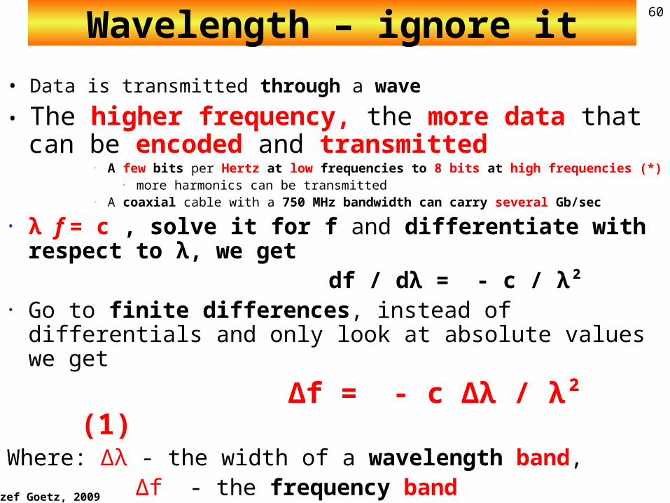
• Data is transmitted through a wave
• The higher frequency, the more data that can be encoded and transmitted
• A few bits per Hertz at low frequencies to 8 bits at high frequencies (*)
• more harmonics can be transmitted• A coaxial cable with a 750 MHz bandwidth can carry several Gb/sec
• λ f = c , solve it for f and differentiate with respect to λ, we get
df / dλ = - c / 법 Go to finite differences, instead of differentials
and only look at absolute values we get
Δf = - c Δλ / λ² (1)Where: Δλ - the width of a wavelength band,
Δf - the frequency band
Jozef Goetz, 2009
61
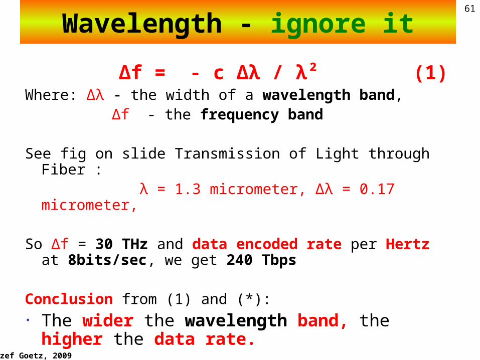
Δf = - c Δλ / λ² (1)Where: Δλ - the width of a wavelength band,
Δf - the frequency band
See fig on slide Transmission of Light through Fiber : λ = 1.3 micrometer, Δλ = 0.17 micrometer,
So Δf = 30 THz and data encoded rate per Hertz at 8bits/sec, we get 240 Tbps
Conclusion from (1) and (*):• The wider the wavelength band, the
higher the data rate.
WavelengthWavelength - ignore it