excel 10 w7750a,b,c constant volume ahu controller - honeywell · excel 10 w7750a,b,c constant...
TRANSCRIPT

SYSTEM ENGINEERING
74-2958�2
Excel 10W7750A,B,C CONSTANT VOLUME AHU CONTROLLER
ContentsIntroduction .................................................................................................................................. 6
Description of Devices .............................................................................................. 6Control Application .................................................................................................... 6Control Provided ....................................................................................................... 7Products Covered...................................................................................................... 8Applicable Literature ................................................................................................. 8Organization of Manual ............................................................................................. 8Product Names ......................................................................................................... 8Agency Listings ......................................................................................................... 8Abbreviations and Definitions.................................................................................... 9Construction .............................................................................................................. 11
Controllers ........................................................................................................... 11Performance Specifications ............................................................................. 13LONMARK® Functional Profile .......................................................................... 17
Inputs/Outputs ..................................................................................................... 18Analog Inputs................................................................................................... 18Digital Inputs .................................................................................................... 19Triac Outputs (W7750B,C Models Only) ......................................................... 19Digital Outputs ................................................................................................. 19
Wall Modules ....................................................................................................... 20Duct Sensor ......................................................................................................... 20
Configurations ........................................................................................................... 21General ................................................................................................................ 21Allowable Heating and Cooling Equipment Configurations ................................. 23
Staged Heating/Cooling Control ...................................................................... 24Modulating Heating/Cooling Control ................................................................ 24Heat Pump Control .......................................................................................... 24Economizer Control ......................................................................................... 25Pneumatic Actuator Control............................................................................. 26Mixed Output-type Control............................................................................... 26
Occupancy Sensor .............................................................................................. 26Window Open/Closed Digital Input ...................................................................... 26Wall Module Options ........................................................................................... 26Dirty Filter Monitor ............................................................................................... 27Indoor Air Quality (IAQ) Override ........................................................................ 27Smoke Control ..................................................................................................... 27Freeze Stat (W7750B2011 or W7750C) .............................................................. 27
Modes of Operation................................................................................................... 27
Application Steps .................................................................................................................................. 28Overview ................................................................................................................... 28Step 1. Plan the System............................................................................................ 29Step 2. Determine Other Bus Devices Required....................................................... 29Step 3. Lay Out Communications and Power Wiring ................................................ 30
LONWORKS® Bus Layout ..................................................................................... 30Power Wiring ....................................................................................................... 32
Power Budget Calculation Example ................................................................ 32Line Loss ......................................................................................................... 32
Step 4. Prepare Wiring Diagrams.............................................................................. 35

EXCEL 10 W7750A,B,C CONSTANT VOLUME AHU CONTROLLER
74-2958�2 2
General Considerations ...................................................................................... 35W7750 Controllers .............................................................................................. 35
Factory Default Digital Outputs........................................................................ 37LONWORKS® Bus Termination Module ................................................................ 43
Step 5. Order Equipment .......................................................................................... 45Step 6. Configure Controllers.................................................................................... 48Step 7. Troubleshooting ............................................................................................ 48
Troubleshooting Excel 10 Controllers and Wall Modules .................................... 48Temperature Sensor and Setpoint Potentiometer Resistance Ranges ............... 49Alarms ................................................................................................................. 49Broadcasting the Service Message ..................................................................... 50W7750 Controller Status LED ............................................................................. 51T7770C,D Wall Module Bypass Pushbutton and Override LED ......................... 51T7560A,B Bypass Pushbutton and LCD Display Occupancy Symbols ............... 51
Appendices .................................................................................................................................. 52Appendix A: Using LONSPEC�/Care to Commission a W7750 Controller................ 52
Sensor Calibration ............................................................................................... 52Setting the Pid Parameters ................................................................................. 52
Appendix B: Sequences of Operation....................................................................... 53Common Operations ........................................................................................... 53
Room Temperature Sensor (RmTemp) ........................................................... 54Remote Setpoint (RmtStptPot) ........................................................................ 55Setpoint Limits (LoSetptLim and HiSetptLim).................................................. 55Bypass Mode (StatusOvrd and StatusLed)...................................................... 55BYPASSTIME.................................................................................................. 55OverrideType................................................................................................... 55OverridePriority ............................................................................................... 55Cycles per Hour (ubHeatCph and ubCoolCph) ............................................... 55T7770C,D or T7560A,B Wall Module Bypass Pushbutton Operation ............. 55Standby Mode (StatusOcySen) ....................................................................... 56Continuous Unoccupied Mode ........................................................................ 56Occupancy Mode and Manual Override Arbitration ........................................ 56Time Clock (Occ_Time_Clock) ........................................................................ 57Schedule Master (Sched_Master)................................................................... 57Setpoint Ramping............................................................................................ 57Recovery Ramping for Heat Pump Systems................................................... 57Fan Operation ................................................................................................. 58Window Sensor (StatusWndw)........................................................................ 58Smoke Control................................................................................................. 58Demand Limit Control (DLC) ........................................................................... 58Dirty Filter Monitor ........................................................................................... 59Start-Up ........................................................................................................... 59
Temperature Control Operations ......................................................................... 59Staged Cooling Control ................................................................................... 59Staged Heating Control ................................................................................... 60Cascade Control of Modulating Cooling/Heating ............................................ 61Series 60 Modulating Control .......................................................................... 61Pulse Width Modulating (PWM) Control .......................................................... 61Outdoor Air Lockout of Heating/Cooling.......................................................... 61Economizer Damper Control ........................................................................... 61Indoor Air Quality (IAQ) Override .................................................................... 61Freeze Stat ...................................................................................................... 62Discharge Air Low Limit Control ...................................................................... 62Economizer Enable/Disable Control................................................................ 62
Appendix C: Complete List of Excel 10 W7750 Controller User Addresses ............. 63User Address Indexes ......................................................................................... 63Mappable User Addresses and Table Number ................................................... 65Failure Detect User Addresses and Table Number ............................................. 65
Appendix D: XL5000 Q7750A Excel 10 Zone Manager Point Estimating Guide ......109Approximate Memory Size Estimating Procedure. ..............................................109
Appendix E: Sensor Data for Calibration .................................................................. 110Resistance Sensors ............................................................................................ 110Voltage/Current Sensors ..................................................................................... 111
0 A,B,C nt Vol-
HU Con-

EXCEL 10 W7750A,B,C CONSTANT VOLUME AHU CONTROLLER
3 74-2958�2
List of FiguresFig. 1. Typical system overview. ................................................................................................................................................ 6Fig. 2. Typical W7750 control application. ................................................................................................................................. 7Fig. 3. Excel 10 W7750A Constant Volume AHU Controller. ..................................................................................................... 12Fig. 4. W7750A construction in in. (mm). ................................................................................................................................... 13Fig. 5. Excel 10 W7750B Constant Volume AHU Controller. ..................................................................................................... 14Fig. 6. Excel 10 W7750C Constant Volume AHU Controller. .................................................................................................... 15Fig. 7. W7750B,C construction in in. (mm). W7750C (shown) has three 4 to 20 mA analog outputs.) ..................................... 16Fig. 8. DIN rail adapters. ............................................................................................................................................................ 17Fig. 9. Functional profile of LONMARK® RTU object details (variables not implemented in Excel 10 CVAHU are greyed). ....... 18Fig. 10. T7770A,B,C,D construction in in. (mm). ....................................................................................................................... 20Fig. 11. T7560A,B construction in in. (mm)................................................................................................................................. 21Fig. 12. C7770A construction in in. (mm).................................................................................................................................... 21Fig. 13. Fan with two stages of heating and two stages of cooling............................................................................................. 24Fig. 14. Fan, modulating heating and modulating cooling. ......................................................................................................... 24Fig. 15. Heat pump with two compressors and auxiliary heat stage(s)....................................................................................... 25Fig. 16. Economizer control. ...................................................................................................................................................... 25Fig. 17. Modulating heat with pneumatic valve actuator. ............................................................................................................ 26Fig. 18. Connecting the portable operator terminal to the LONWORKS® Bus.............................................................................. 29Fig. 19. Wiring layout for one doubly terminated daisy-chain LONWORKS® Bus segment. ........................................................ 31Fig. 20. Wiring layout for two singly terminated LONWORKS® Bus segments. ............................................................................ 32Fig. 21. NEMA class 2 transformer voltage output limits. ........................................................................................................... 33Fig. 22. Power wiring details for one Excel 10 per transformer. ................................................................................................. 33Fig. 23. Power wiring details for two or more Excel 10s per transformer. .................................................................................. 34Fig. 24. Transformer power wiring details for one Excel 10 used in UL 1995 equipment (U.S. only)......................................... 34Fig. 25. Attaching two or more wires at terminal blocks.............................................................................................................. 36Fig. 26. W7750B High-Side/Low-Side selectable switching and jumper location (on W7750B2011 and W7750C)................... 36Fig. 27. Typical W7750A Controller AHU application wiring. (For more information on note 2, refer to Fig. 25.)....................... 38Fig. 28. Typical W7750A Controller with separate transformer application wiring.
(For more information on note 2, refer to Fig. 25.) ............................................................................................................ 38Fig. 29. W7750A Controller floating economizer damper wiring. (For more information on note 2, refer to Fig. 25.)................. 39Fig. 30. Typical W7750B Controller with staged heating and cooling wiring. (For more information on note 2, refer to Fig. 25.) 40Fig. 31. W7750B Controller with floating heating, cooling and economizer wiring.
(For more information on note 2, refer to Fig. 25.) ............................................................................................................ 40Fig. 32. W7750B,C Controller PWM damper actuator wiring. (For more information on note 2, refer to Fig. 25.) ..................... 41Fig. 33. W7750B,C wiring with 4 to 20 mA enthalpy sensors and digital inputs.
(For more information on note 2, refer to Fig. 25.) ............................................................................................................ 41Fig. 34. W7750B,C wiring with C7600C 4 to 20 mA solid state humidity sensor.
(For more information on note 2, refer to Fig. 25.) ............................................................................................................ 42Fig. 35. W7750C Controller with 4 to 20 mA heating, cooling and economizer wiring. AOs must use terminals 16, 17 or 18.
The AOs can be set to be reverse acting. (For more information on note 2, refer to Fig. 25.)......................................... 42Fig. 36. Pneumatic transducer to W7750B,C.............................................................................................................................. 43Fig. 37. RP7517,B pneumatic transducer to W7750C. ............................................................................................................... 43Fig. 38. Typical doubly terminated daisy-chain LONWORKS® Bus segment termination module wiring. ................................... 44Fig. 39. LONWORKS® Bus termination wiring options. ............................................................................................................... 45Fig. 40. Temperature sensor resistance plots............................................................................................................................. 49Fig. 41. Location of the Service Pin Button................................................................................................................................. 51Fig. 42. LED location on W7750. ................................................................................................................................................ 51Fig. 43. The T7770C,D Wall Modules LED and Bypass pushbutton locations. .......................................................................... 51Fig. 44. T7560A,B Digital Wall Module Bypass pushbutton location. ......................................................................................... 51Fig. 45. LED and Bypass pushbutton operation. ....................................................................................................................... 56Fig. 46. Setpoint ramping parameters with ramp rate calculation............................................................................................... 57Fig. 47. Setpoint ramping parameters with setpoint calculation.................................................................................................. 58Fig. 48. Setpoint ramping parameters with ramp rate calculation............................................................................................... 58Fig. 49. Schematic diagram for a typical W7750B Unit. ............................................................................................................. 59Fig. 50. Staged output control versus PID Error. ....................................................................................................................... 60Fig. 51. Point capacity estimate for Zone Manager. .................................................................................................................. 109Fig. 52. PT3000 Sensor resistance versus temperature............................................................................................................. 110Fig. 53. 20K ohm sensor resistance versus temperature. .......................................................................................................... 110Fig. 54. C7600B Sensor voltage versus humidity. ...................................................................................................................... 111
Excel 10 W7750A,B,C Constant Vol-ume AHU Con-troller

EXCEL 10 W7750A,B,C CONSTANT VOLUME AHU CONTROLLER
74-2958�2 4
Fig. 55. C7600C output current versus humidity......................................................................................................................... 111Fig. 56. C7400A Sensor current versus enthalpy (volts). ........................................................................................................... 112Fig. 57. Partial psychrometric chart for a C7400A Solid State Enthalpy Sensor. ...................................................................... 113Fig. 58. C7400A Solid State Enthalpy Sensor output current versus relative humidity. ............................................................. 113Fig. 59. C7232, C7632 voltage versus CO2 concentration. ........................................................................................................ 114Fig. 60. P7640 voltage (Vdc) versus pressure (in. w.c.). ............................................................................................................ 114

EXCEL 10 W7750A,B,C CONSTANT VOLUME AHU CONTROLLER
5 74-2958�2
List of TablesTable 1. Agency Listing. ............................................................................................................................................................. 9Table 2. List of Differences in W7750A and W7750B,C Controllers........................................................................................... 11Table 3. Common Configuration Options Summary For W7750A,B,C Controllers..................................................................... 22Table 4. Configuration Options Summary for W7750A,B,C Controllers. .................................................................................... 23Table 5. Modes Of Operation For The Excel 10 W7750 Controller . .......................................................................................... 27Table 6. Application Steps. ......................................................................................................................................................... 28Table 7. LONWORKS® Bus Configuration Rules and Device Node Numbers. ............................................................................ 30Table 8. VA Ratings For Transformer Sizing. ............................................................................................................................. 32Table 9. Field Wiring Reference Table (Honeywell listed as AK#### or equivalent).................................................................. 35Table 10. W7750A Version I/O Description. ............................................................................................................................... 37Table 11. Excel 10 W7750 Controller Ordering Information. ...................................................................................................... 46Table 12. Excel 10 Alarms. ......................................................................................................................................................... 50Table 13. Recommended Values For PID Parameters............................................................................................................... 52Table 14. Common Configuration Options Summary For W7750A,B,C Controllers................................................................... 53Table 15. Configuration Options Summary For W7750A,B,C Controllers. ................................................................................. 54Table 16. Bypass Pushbutton Operation. ................................................................................................................................... 55Table 17. Interstage Minimum Times.......................................................................................................................................... 60Table 18. Excel 10 W7750 Controller User Address Point Types. ............................................................................................. 63Table 19. Engineering Units For Analog Points. ......................................................................................................................... 66Table 20. Input/Output Points. .................................................................................................................................................... 67Table 21. Control Parameters..................................................................................................................................................... 74Table 22. Energy Management Points........................................................................................................................................ 78Table 23. Status Points............................................................................................................................................................... 81Table 24. Calibration Points........................................................................................................................................................ 93Table 25. Configuration Parameters. .......................................................................................................................................... 94Table 26. LONMARK®/Open System Points. ............................................................................................................................... 98Table 27. Direct Access And Special Points............................................................................................................................... 106Table 28. Data Share Points....................................................................................................................................................... 108Table 29. PT3000 Sensor Resistance Versus Temperature. ..................................................................................................... 110Table 30. C7600B Sensor Voltage Versus Humidity. ................................................................................................................. 111Table 31. C7600C Sensor Current Versus Humidity. ................................................................................................................. 111Table 32. C7400A Sensor Current Versus Enthalpy (volts)........................................................................................................ 112Table 33. C7232, C7632 Voltage Versus CO2 Concentration. ................................................................................................... 114Table 34. P7640 Voltage (Vdc) Versus Pressure (in. w.c.)......................................................................................................... 114
Excel 10 W7750A,B,C Constant Vol-ume AHU Con-troller

EXCEL 10 W7750A,B,C CONSTANT VOLUME AHU CONTROLLER
74-2958�2 6
INTRODUCTION
Description of DevicesThe W7750 is the Constant Volume Air Handling Unit (CVAHU) Controller in the Excel 10 product line family. The CVAHU is a LONMARK® compliant device designed to control single zone and heat pump air handlers. W7750 systems control the space temperature in a given zone by regulating the heating and cooling equipment in the air handler that delivers air to that space. The W7750 air handler is typically an all-in-one constant air volume packaged unit, located on the roof of the building. In addition to standard heating and cooling control, the W7750 provides many options and advanced system features that allow state-of-the-art commercial building control. The W7750 Controller is capable of stand-alone operation; however, optimum functional benefits are achieved when the network communication capabilities are used. The W7750 utilizes the Echelon® LONWORKS® network (LONWORKS Bus) for communications, and conforms with the LONMARK HVAC Interoperability standard for Roof Top Unit Controllers (see Fig. 9).
The T7770 or T7560 direct-wired Wall Modules are used in conjunction with W7750 Controllers. The zone controlled by the W7750 Controller typically can use a T7770A through D or a T7560A,B Wall Module. Additional features available in T7770A through D models include analog setpoint input knob, override digital input pushbutton, override status LED and LONWORKS Bus network access jack. Additional features available in T7560A,B models include analog setpoint input knob, override digital input pushbutton, humidity sensor (T7650B model), override status LCD and digital display.
The Q7750A Excel 10 Zone Manager is a communications interface that allows devices on the LONWORKS Bus network to communicate with devices on the standard EXCEL 5000® System C-Bus. Fig. 1 shows an overview of a typical system layout. The Q7750A also provides some control and monitoring functions.
Fig. 1. Typical system overview.
Control ApplicationW7750 systems in commercial buildings typically incorporate a packaged air handler system that delivers a constant volume of air at preconditioned temperatures to the zone being served. Each zone is usually serviced by a separate AHU; however, sometimes two or more AHUs service the same zone. Note that the W7750 is not designed to control Variable Air Volume (VAV) air handlers or Multi-Zone air handlers, where one air handler simultaneously controls the space temperature in many zones.
The W7750 can control staged or modulating heating and cooling coils, mixed air economizer dampers, and the system fan. Control of heat pump units, where the compressor(s) is used for both cooling and heating, is also provided. The zone the W7750 services can use a T7770 or T7650 for space temperature sensing and an LONWORKS Bus network access for users. Fig. 2 shows a typical W7750 control application.
PERSONAL COMPUTER TOOLS
LONSPEC, LONSTATION OR
CARE
Q7752A
LONWORKS BUS
SERIAL
ADAPTER
EXCEL 10
Q7750A
ZONE
MANAGER
C-BUS COMMUNICATION NETWORK
EXCEL 500EXCEL BUILDING SUPERVISOR
C-BUS TO LONWORKS BUS
INTERFACE DEVICE
EXCEL 10 W7751F
PANEL PLENUM
MOUNT VERSION
VARIABLE AIR VOLUME
CONTROLLER
LONWORKS-BUS COMMUNICATIONS NETWORK LONWORKS BUS COMMUNICATIONS NETWORK
Q7751A
FTT
LONWORKS BUS
ROUTER
EXCEL 10 T7770
WALL MODULE
EXCEL 10 T7560A, B
WALL MODULE
M17487A
EXCEL 10
W7750B
CVAHU
CONTROLLER
1 2 3 4 5 6 7 8 9 10 11 12 13 14 15 J3
31 30 29 28 27 26 25 24 23 22 21 20 19 18 17 16
Q7740A
2-WAY
REPEATER
0 A,B,C nt Vol-
HU Con-

EXCEL 10 W7750A,B,C CONSTANT VOLUME AHU CONTROLLER
7 74-2958�2
Fig. 2. Typical W7750 control application.
Control ProvidedThe W7750 Controller is designed to control a single air handler to maintain the units space temperature at the current setpoint. Heating and cooling control is provided for either staged or modulating equipment. Up to four stages of mechanical cooling and up to four stages of heating are allowed. Modulating outputs can be either floating type such as a Series 60 control, or Pulse Width Modulated (PWM W7750B,C only) control.
The economizer dampers can be controlled directly with floating or PWM outputs, or indirectly using a digital output as an enable/disable signal to a packaged economizer controller. The economizer enable function, which decides when to allow outdoor air to be used for free cooling, can be configured to one of ten strategies based on the inputs. For more details, see Appendix B�Sequences of Operation. When the economizer position is controlled from the W7750, the minimum position setting (for ventilation requirements) can be adjusted based on indoor air quality (IAQ) needs in the space. IAQ monitoring is provided through either a CO2 sensor or a digital input from a space-mounted IAQ limit switch.
For heat pump configurations, up to four compressors can be controlled, along with up to four stages of auxiliary heat, and a heat/cool change over valve. Including the supply fan, the combination of these items may not exceed eight outputs if a W7750B,C is used, or six outputs for a W7750A. (The eight outputs on the W7750C consist of five digital and three analog outputs.)
Like the W7751 VAV Box Controller, the W7750 Controller can monitor a space-mounted occupancy sensor, and a door/window contact. These inputs affect the operational mode of the controller (see Table 5 for a list of all possible modes of operation).
The W7750 Controller allows other controllers in the system to use the W7750s physical inputs and outputs. A digital input and an analog input can be configured to read switch states and voltage sensor values, respectively, and send them out over the LONWORKS Bus network. The Q7750A Zone Manager can use these values in custom control strategies. Additionally, two of the W7750 digital outputs are available for control program use. These outputs only respond to signals sent over the network, and are not controlled by the W7750 internal control algorithms.
WINDOW CONTACT
OCCUPANCYSENSOR
M
OA TEMP
FILTER
FAN
COOLCOIL
HEATCOIL
DA TEMPRA TEMP
EXCEL 10W7750CVAHU
T7770 OR T7560A,BRETURNAIR
DISCHARGEAIR
OUTDOORAIR
CEILING
ROOF
- +
M17488

EXCEL 10 W7750A,B,C CONSTANT VOLUME AHU CONTROLLER
74-2958�2 8
Products CoveredThis System Engineering Guide describes how to apply the Excel 10 family of W7750 CVAHU Controllers and related accessories to typical applications. The specific devices covered include:� W7750A,B,C Controllers.� T7770A through D Wall Modules.� T7560A,B Wall Modules.� Q7751A,B Router (FTT to FTT and TPT to FTT).� Q7752A Serial Interface.� Q7740A,B Repeaters (2-way and 4-way).� 209541B FTT Termination Module.
Applicable LiteratureThe following list of documents contains information related to the Excel 10 W7750 CVAHU Controller and the LCBS/ EXCEL 5000® OPEN� SYSTEM in general:
Organization of ManualThis manual is divided into three basic parts: the Introduction, the Application Steps, and the Appendices that provide supporting information. The Introduction and Application Steps 1 through 5 provide the information needed to make accurate material ordering decisions. Application Step 6 and
the Appendices include configuration engineering that can be started using LONSPEC� or Care PC Software after the devices and accessories are ordered. Application Step 7 is troubleshooting.
The organization of the manual assumes a project is being engineered from start to finish. If an operator is adding to, or is changing an existing system, the Table of Contents can provide the relevant information.
Product NamesThe W7750 Controller is available in three models:� W7750A Constant Volume AHU Controller - W7750A
Version.� W7750B Constant Volume AHU Controller - W7750B
Version.� W7750C Constant Volume AHU Controller - W7750C
Version.
The T7770 Wall Module is available in four models. The T7770 Wall Modules will work with all Excel 5000 and Excel 10 Controllers (except the W7751A,C,E,G):� T7770A1xxx Wall Module with nonlinearized 20K ohm
NTC sensor only.� T7770A2xxx Wall Module with nonlinearized 20K ohm
NTC sensor and LONWORKS Bus jack.� T7770A3xxx Wall Module with nonlinearized 10K ohm
NTC sensor for averaging two sensors.� T7770B1xxx Wall Module with nonlinearized 20K ohm
NTC sensor, 10K ohm setpoint, and LONWORKS Bus jack.� T7770C1xxx Wall Module with nonlinearized 20K ohm
NTC sensor, 10K ohm setpoint, bypass button and LED, and LONWORKS Bus jack.
� T7770D1xxx Wall Module with nonlinearized 20K ohm NTC sensor, bypass button and LED, and LONWORKS Bus jack.
NOTE: The T7770B,C Models are available with a absolute 55 to 85°F (10 to 85°C) or a relative scale plate adjustable to ±9°F (±5°C).
The T7560A,B Wall Module is available in two models:� T7560A Wall Module displays and provides space
temperature, setpoint, Occ/Unocc override, override status LCD and digital display.
� T7560B Wall Module displays and provides space temperature, humidity sensor, setpoint, Occ/Unocc override, override status LCD and digital display.
Other products:� Q7750A Excel 10 Zone Manager.� Q7751A,B Bus Router.� Q7752A Serial Adapter.� Q7740A,B FTT Repeaters.� 209541B FTT Termination Module.Refer to Table 11 in Application Step 5. Order Equipment for a complete listing of all available part numbers.
NOTE: The Q7750A Zone Manager is referred to as (E-Link) in internal software and CARE.
Agency ListingsTable 1 provides information on agency listings for Excel 10 products. Be sure to always follow Local Electrical Codes.
Form No Title74-2956 Excel 10 W7750A,B,C Controller Specification Data74-2697 Excel 10 T7770A,B,C,D,E,F,G Wall Module Specification Data74-3097 T7560A,B Digital Wall Module Specification Data74-2950 Excel 10 Q7750A, Zone Manager Specification Data74-2952 Excel 10 Q7751A,B Router Specification Data74-2954 Excel 10 Q7752A Serial Interface Specification Data74-3067 Q7752B PCMCIA LONWORKS PCC-10 Card Specification Data74-2858 Excel 10 Q7740A,B FTT Repeaters Specification Data74-2951 Excel 10 Q7750A Zone Manager Checkout and Test Manual95-7521 Excel 10 W7750A,B,C Controller Installation Instructions95-7538 Excel 10 T7770A-G Wall Module Installation Instructions95-7620 T7560A,B Digital Wall Module Installation Instructions95-7509 Excel 10 Q7750A Zone Manager Installation Instructions95-7510 Excel 10 Q7751A,B Router Installation Instructions95-7511 Excel 10 Q7752A Serial Interface Installation Instructions95-7613 Q7752B PCMCIA LONWORKS PCC-10 Card Installation
Instructions95-7555 Excel 10 Q7740A,B FTT Repeaters Installation Instructions95-7554 Excel 10 209541B Termination Module Installation Instructions74-2937 LONSPEC� User�s Guide74-3068 LONSTATION� User�s Guide74-5587 CARE User�s Manual74-1392 CARE Excel 10 Zone Manager User�s Guide74-5577 CARE Icon Guide74-2039 XBS User�s Manual74-5018 XBS Application Guide

EXCEL 10 W7750A,B,C CONSTANT VOLUME AHU CONTROLLER
9 74-2958�2
Table 1. Agency Listing.
Abbreviations and DefinitionsAHU⎯Air Handling Unit; the central fan system that includes
the blower, heating equipment, cooling equipment, ventilation air equipment, and other related equipment.
CO⎯Carbon Monoxide. Occasionally used as a measure of indoor air quality.
CO2⎯Carbon Dioxide. Often used as a measure of indoor air quality.
CARE⎯Computer Aided Regulation Engineering; the PC based tool used to configure C-Bus and LONWORKS Bus devices.
C-Bus⎯Honeywell proprietary Control Bus for communications between EXCEL 5000® System controllers and components.
CPU⎯Central Processing Unit; an EXCEL 5000® OPEN™ SYSTEM controller module.
cUL⎯Underwriters Laboratories Canada
CVAHU⎯Constant Volume AHU; refers to a type of air handler with a single-speed fan that provides a constant amount of supply air to the space it serves.
DDF⎯Delta Degrees Fahrenheit.
D/X⎯Direct Expansion; refers to a type of mechanical cooling where refrigerant is (expanded) to its cold state, within a heat-exchanging coil that is mounted in the air stream supplied to the conditioned space.
Echelon⎯The company that developed the LONWORKS Busand the Neuron® chips used to communicate on theLONWORKS Bus.
Economizer⎯Refers to the mixed-air dampers that regulate the quantity of outdoor air that enters the building. In cool outdoor conditions, fresh air can be used to supplement the mechanical cooling equipment. Because this action saves energy, the dampers are often referred to as economizer dampers.
EMI⎯Electromagnetic Interference; electrical noise that can cause problems with communications signals.
E-Link⎯Refers to the Q7750A Zone Manager. This name is used in internal software and in CARE software.
EMS⎯Energy Management System; refers to the controllers and algorithms responsible for calculating optimum operational parameters for maximum energy savings in the building.
Device Agency CommentsW7750A,B,C Controllers UL Tested and listed under UL916 (file number E87741). The CVAHU W7750A,B,C
Controllers are UL94-5V listed and suitable for plenum mounting.cUL Listed (E87741).CE General Immunity per European Consortium Standards EN50081-1 (CISPR 22, Class B)
and EN 50082-1:1992 (based on Residential, Commercial, and Light Industrial).EN 61000-4-2: IEC 1000-4-2 (IEC 801-2) Electromagnetic Discharge.EN 50140, EN 50204: IEC 1000-4-3 (IEC 801-3) Radiated Electromagnetic Field.EN 61000-4-4: IEC 1000-4-4 (IEC 801-4)
Electrical Fast Transient (Burst). Radiated Emissions and Conducted Emissions:
EN 55022: 1987 Class B.CISPR-22: 1985.
FCC Complies with requirements in FCC Part 15 rules for a Class B Computing Device. Operation in a residential area can cause interference to radio or TV reception and require the operator to take steps necessary to correct the interference.
T7770A,B,C,D and T7560A,B Wall Modules
UL (Not applicable.)cUL (Not applicable.)FCC (Not applicable.)
Q7750A Excel 10 Zone Manager UL Tested and listed under UL916, file number S4804 (QVAX, PAZY).
CSA Listing pending.FCC Complies with requirements in FCC Part 15 rules for a Class A Computing Device.
Operation in a residential area can cause interference to radio or TV reception and require the operator to take steps necessary to correct the interference.
Q7740A,B FTT Repeaters, Q7751A,B Routers and
UL UL1784.
Q7752A Serial Adapter CSA Listed.FCC Complies with requirements in FCC Part 15 rules for a Class B Computing Device.

EXCEL 10 W7750A,B,C CONSTANT VOLUME AHU CONTROLLER
74-2958�2 10
EEPROM⎯Electrically Erasable Programmable Read Only Memory; the variable storage area for saving user setpoint values and factory calibration information.
Enthalpy⎯The energy content of air measured in BTUs per pound (KiloJoules per Kg).
EPROM⎯Erasable Programmable Read Only Memory; the firmware that contains the control algorithms for the Excel 10 Controller.
Excel 10 Zone Manager⎯A controller that is used to interface between the C-Bus and the LONWORKS Bus. The Excel 10 Zone Manager also has the functionality of an Excel 100 Controller, but has no physical I/O points.
NOTE: The Q7750A Zone Manager can be referred to as E-Link in the internal software, CARE.
E-Vision⎯User interface software used with devices that operate via the FTT LONWORKS Bus communications protocol.
Firmware⎯Software stored in a nonvolatile memory medium such as an EPROM.
Floating Control⎯Refers to Series 60 Modulating Control of a valve or damper. Floating Control utilizes one digital output to pulse the actuator open, and another digital output to pulse it closed.
FTT⎯Free Topology Transceiver.
IAQ⎯Indoor Air Quality. Refers to the quality of the air in the conditioned space, as it relates to occupant health and comfort.
I/O⎯Input/Output; the physical sensors and actuators connected to a controller.
I x R⎯I times R or current times resistance; refers to Ohms Law: V = I x R.
K⎯Degrees Kelvin.
Level IV⎯Refers to a classification of digital communication wire. Formerly known as UL Level IV, but not equivalent to Category IV cable. If there is any question about wire compatibility, use Honeywell-approved cables (see Step 5 Order Equipment section).
LONWORKS Bus⎯Echelons LONWORKS network for communication among Excel 10 Controllers.
LONWORKS Bus Segment⎯An LONWORKS Bus section containing no more than 60 Excel 10s. Two segments can be joined together using a router.
NEC⎯National Electrical Code; the body of standards for safe field-wiring practices.
NEMA⎯National Electrical Manufacturers Association; the standards developed by an organization of companies for safe field wiring practices.
Node⎯A Communications Connection on a network; an Excel 10 Controller is one node on the LONWORKS Bus network.
NV⎯Network Variable; an Excel 10 parameter that can be viewed or modified over the LONWORKS Bus network.
PC⎯An Personal Computer with Pentium processor capable of running Microsoft® Windows™ 95.
Pot⎯Potentiometer. A variable resistance electronic component located on the T7770B,C or T7560A,B Wall Modules; used to allow user-adjusted setpoints to be input into the Excel 10 Controllers.
PWM⎯Pulse Width Modulated output; allows analog modulating control of equipment using a digital output on the controller.
RTD⎯Resistance Temperature Detector; refers to a type of temperature sensor whose resistance output changes according to the temperature change of the sensing element.
Subnet⎯A LONWORKS Bus segment that is separated by a router or repeater.
TOD⎯Time-Of-Day; the scheduling of Occupied and Unoccupied times of operation.
TPT⎯Twisted Pair Transceiver.
VA⎯Volt Amperes; a measure of electrical power output or consumption as applies to an ac device.
Vac⎯Voltage alternating current; ac voltage rather than dc voltage.
VAV⎯Variable Air Volume; refers to either a type of air distribution system, or to the W7751 Excel 10 VAV Box Controller that controls a single zone in a variable air volume delivery system.
VOC⎯Volatile Organic Compound; refers to a class of common pollutants sometimes found in buildings. Sources include out-gassing of construction materials, production-line by-products, and general cleaning solvents. A VOC is occasionally used as a measure of indoor air quality.
W7750⎯The model number of the Excel 10 CVAHU Controllers (also see CVAHU).
W7751⎯The model number of the Excel 10 VAV Box Controllers (also see VAV).
Wall Module⎯The Excel 10 Space Temperature Sensor and other optional controller inputs are contained in the T7770 or the T7560A,B Wall Modules. See Application Step 5. Order Equipment for details on the various models of Wall Modules.
XBS⎯Excel Building Supervisor; a PC based tool for monitoring and changing parameters in C-Bus devices.

EXCEL 10 W7750A,B,C CONSTANT VOLUME AHU CONTROLLER
11 74-2958�2
Construction
ControllersThe Excel 10 W7750 Controller is available in three different models. The W7750A Model, which is a low cost controller made for simple single zone air handlers and heat pump controls. The W7750B,C Models are intended for more complex applications.
The W7750B,C Models use Triacs for their digital outputs, where as the W7750A Model uses dry-contact relays. The W7750C Model also has three analog outputs available on terminals 16, 17 and 18.
All wiring connections to the controller are made at screw terminal blocks. Connection for operator access to the LONWORKS Bus is provided by plugging the SLTA connector cable into the LONWORKS Bus communications jack.
The W7750A,B,C Models consist of a single circuit board that is mounted in a sheet metal subbase and protected by a factory snap-on cover. The three controllers have the same physical appearance except for terminals 16 through 20
(W7750A) and different labels next to the wiring terminals (see Fig. 3, 5 or 6). Wires are attached to the screw terminal blocks on both sides of the controller. The controllers mount with two screws (see Fig. 4 or 7). The W7750 can also be mounted using DIN rail. To mount the W7750 on DIN rail, purchase two DIN rail adapters (obtain locally) part number TKAD, from Thomas and Betts, see Fig. 8, then snap onto standard EN 50 022 35 mm by 7.5 mm (1-3/8 in. by 5/16 in.) DIN rail. DIN rail is available through local suppliers.
A channel in the cover allows the controller status LED to be visible when the cover is in place. There are no field-serviceable parts on the circuit board and, therefore, it is intended that the cover never be removed.
The W7750A,B,C can be mounted in any orientation. Ventilation openings were designed into the cover to allow proper heat dissipation regardless of the mounting orientation. See Fig. 4 and 7.
The input/output and control differences between the two models are summarized in Table 2. The I/O points in Table 2 are the free I/O points that are not reserved for Wall Module use.
Table 2. List of Differences in W7750A and W7750B,C Controllers.
a The T7770 or the T7560 Wall Modules includes I/O points for two analog inputs for the space temperature and the setpoint knob, a digital input for the Bypass pushbutton, and a digital output for the LED Bypass Indicator. These W7750 I/O points are configurable, but are normally used for the Wall Module.
W7750A Model W7750B,C ModelsDigital Outputs Six Relay Outputs Eight Triac Outputs (Five Triac outputs on W7750C)Digital Inputs Two FourWall Module One* Onea
Analog Outputs None Three 4 to 20 mA Outputs (W7750C only)Analog Inputs One (Resistive Input Only) Four (Two Resistive and two Voltage/Current Inputs)DC Power None 20 Vdc available to power optional sensorsFloating (Series 60) Control Economizer Only Heating, Cooling, and/or EconomizerPWM Control None Heating, Cooling, and/or Economizer

EXCEL 10 W7750A,B,C CONSTANT VOLUME AHU CONTROLLER
74-2958�2 12
Fig. 3. Excel 10 W7750A Constant Volume AHU Controller.
M10099B
1 2 3 4 5 6 7 8 9 10 11 12 13 14 15 J3
31 30 29 28 27 26 25 24 23 22 21 20 19 18 17 16
EGND
LED SNSR GND SET PT AI-1 OHM
GND DI-1 GND GND DI-2 NOTUSED
LONWORKSBUS
LON
JACK
W1 W2 Y1 Y2 GNETWORK
DO Rc Rh24
VAC
W7750A
24 VACCOM
NOTUSED
NOTUSED
NOTUSED
NOTUSED
NOTUSED
BYPASS
EXCEL 10 W7750A,B,C CONSTANT VOLUME AHU CONTROLLER
13 74-2958�2
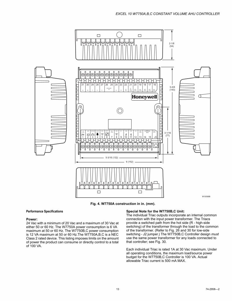
Fig. 4. W7750A construction in in. (mm).
Performance Specifications
Power:24 Vac with a minimum of 20 Vac and a maximum of 30 Vac at either 50 or 60 Hz. The W7750A power consumption is 6 VA maximum at 50 or 60 Hz. The W7750B,C power consumption is 12 VA maximum at 50 or 60 Hz.The W7750A,B,C is a NEC Class 2 rated device. This listing imposes limits on the amount of power the product can consume or directly control to a total of 100 VA.
Special Note for the W7750B,C Unit:The individual Triac outputs incorporate an internal common connection with the input power transformer. The Triacs provide a switched path from the hot side (R - high-side switching) of the transformer through the load to the common of the transformer. (Refer to Fig. 26 and 30 for low-side switching - J2 jumper.) The W7750B,C Controller design must use the same power transformer for any loads connected to that controller; see Fig. 30.
Each individual Triac is rated 1A at 30 Vac maximum. Under all operating conditions, the maximum load/source power budget for the W7750B,C Controller is 100 VA. Actual allowable Triac current is 500 mA MAX.
1 2 3 4 5 6 7 8 9 10 11 12 13 14 15 J3
E
GND
LED BYPASS SNSR GND SET PT AI-1
OHM
GND DI-1 GND GND DI-2 NOT
USEDLONWORKS
BUS
LON
JACK
31 30 29 28 27 26 25 24 23 22 21 20 19 18 17 16
WI W2 Y1 Y2 G
NEYWORK
DORc Rh
24
VAC
5-3/16 (132)
5-5/8(143)
3-1/16(77)
2-1/8(54)
6 (152)
M10098B
24
VAC
COM
NOT
USEDNOT
USED
NOT
USEDNOT
USED
NOT
USED

EXCEL 10 W7750A,B,C CONSTANT VOLUME AHU CONTROLLER
74-2958�2 14
Fig. 5. Excel 10 W7750B Constant Volume AHU Controller.
CPU:Motorola or Toshiba 3150 Neuron processor, containing three eight-bit CPUs. Each Neuron has a unique 48-bit network identification number.
Memory Capacity:64K ROM/PROM (6K reserved for network operations, 58K usable for control algorithm code).512 bytes EEPROM.2K RAM.
Specified Space Temperature Sensing Range:45 to 99°F (7 to 37°C) with an allowable control setpoint range from 50 to 90°F (10 to 32°C) when initiated from the network and 55 to 85°F (13 to 29°C) when configured and connected to T7770 or T7560 Wall Modules.
M6854B
1 2 3 4 5 6 7 8 9 10 11 12 13 14 15 J3
31 30 29 28 27 26 25 24 23 22 21 20 19 18 17 16
E GND
LED BYPASS SNSRSET PT AI-1
OHMA1-2 OHM
AI-3 V/mA
AI-4V/mA
20VDCOUT
DI-4DI-3 DI-2
DI-1VAC24
VAC24
COM1
OUT2
OUT3
OUT4
OUT5
OUT6
OUT7
OUT8
OUT
AIGND AI
GND AIGND LONWORKS
BUSLON
JACK
DIGND DI
GND

EXCEL 10 W7750A,B,C CONSTANT VOLUME AHU CONTROLLER
15 74-2958�2
Fig. 6. Excel 10 W7750C Constant Volume AHU Controller.
M17489
1 2 3 4 5 6 7 8 9 10 11 12 13 14 15 J3
31 30 29 28 27 26 25 24 23 22 21 20 19 18 17 16
E GND
LED BYPASS SNSRSET PT AI-1
OHMA1-2 OHM
AI-3 V/mA
AI-4V/mA
20VDCOUT
DI-4DI-3 DI-2
DI-1VAC24
VAC24
COM1
OUT2
OUT3
OUT4
OUT5
OUTA01
A02
A03
AIGND AI
GND AIGND LONWORKS
BUSLON
JACK
DIGND DI
GND

EXCEL 10 W7750A,B,C CONSTANT VOLUME AHU CONTROLLER
74-2958�2 16
Fig. 7. W7750B,C construction in in. (mm). W7750C (shown) has three 4 to 20 mA analog outputs.)
Communications:The W7750A,B,C Controller uses a Free Topology Transceiver (FTT) transformer-coupled communications port running at 78 kilobits per second (kbps). Using the transformer-coupled communications interface offers a much higher degree of common-mode noise rejection while ensuring dc isolation.
Approved cable types for LONWORKS Bus communications wiring is Level IV 22 AWG (0.34 mm2) plenum or nonplenum rated unshielded, twisted pair, solid conductor wire. For
nonplenum areas, use Level IV 22 AWG (0.34 mm2) such as: U.S. part AK3781 (one pair), U.S. part AK3798 (one pair stranded), or U.S. part AK3782 (two pair). In plenum areas, use plenum-rated Level IV, 22 AWG (0.34 mm2) such as U.S. part AK3791 (one pair) or U.S. part AK3792 (two pair). (See Tables 9 and 11 for part numbers.) Contact Echelon Corp. Technical Support for the recommended vendors of Echelon approved cables.
1 2 3 4 5 6 7 8 9 10 11 12 13 14 15 J3
E GND
LED BYPASS SNSR AIGND
AIGND
AIGND
SET PT AI-1OHM
AI-2OHM
AI-3V/mA
AI-4V/mA
20VDCOUT
LONWORKS
BUSLON
JACK
31 30 29 28 27 26 25 24 23 22 21 20 19 18 17 16
DI-4DI
GNDDI-3 DI-2
DIGND
DI-1VAC24
VAC24
COM1
OUT
2OUT
3OUT
4OUT
5OUT
A01
A02
A03
5-3/16 (132)
5-5/8(143)
3-1/16(77)
2-1/8(54)
6 (152)
M17490

EXCEL 10 W7750A,B,C CONSTANT VOLUME AHU CONTROLLER
17 74-2958�2
Fig. 8. DIN rail adapters.
The FTT supports polarity insensitive free topology wiring. This frees the system installer from wiring using a specific bus topology. T-tap, star, loop, and mixed wiring topologies are all supported by this architecture. The maximum LONWORKS Bus length when using a combination of T-tap, star, loop, and bus wiring (singly terminated) is 1640 ft. (500m) with the maximum node-to-node length of 1312 ft. (400m). In the event that the total wire length is exceeded, then a Q7740A 2-Way Repeater or a Q7740B 4-Way Repeater can be used to allow the number of devices to be spread out as well as increasing the length of wire over which they communicate. The maximum number of repeaters per segment is one. A Q7751A,B LONWORKS Bus Router can also be used to effectively double the maximum LONWORKS Bus length.
NOTE: For LCBS the router must be configured as a repeater.
The advantage of using the router is that it segregates traffic to a segment while when using the repeater, all traffic is repeated on each segment. When utilizing a doubly
terminated LONWORKS Bus structure, use a continuous daisy-chain with no stubs or taps from the main backbone, The maximum LONWORKS Bus length is 4593 ft. (1400m) with the maximum node-to-node length of 3773 ft. (1150m).
FTT networks are very flexible and convenient to install and maintain, but it is imperative to carefully plan the network layout and create and maintain accurate documentation. This aids in compliance verification and future expansion of the FTT network. This also keeps unknown or inaccurate wire run lengths, node-to-node (device-to-device) distances, node counts, total wire length, inaccurate repeater/router locations, and misplaced or missing terminations minimized. Refer to LONWORKS Bus Wiring Guidelines form, 74-2865 for complete description of network topology rules.
LONMARK® FUNCTIONAL PROFILEW7750 Controllers support the LONMARK Functional Profile number 8030 Roof Top Unit Controller, version 1.0 (see Fig. 9).
M6857
1
2
3

EXCEL 10 W7750A,B,C CONSTANT VOLUME AHU CONTROLLER
74-2958�2 18
Fig. 9. Functional profile of LONMARK® RTU object details (variables not implemented in Excel 10 CVAHU are
greyed).
Environmental:Operating Temperature: -40 to 150°F (-40 to 65.5°C).
Shipping Temperature: -40 to 150°F (-40 to 65.5°C).
Relative Humidity: 5% to 95% noncondensing.
Vibration: Rated V2 level compliant.
Inputs/OutputsThe W7750A Unit supports the following hardware features:� Three 20K ohm NTC (2021 ohms at 180°F through
834K ohms at -40F) or PT3000 (3973 ohms at 180ºF through 2916 ohms at -40°F) resistive analog inputs (one reserved for space temperature and one reserved for the setpoint knob).
� Three dry contact digital inputs (one reserved for the Bypass pushbutton).
� LED digital output (only for the wall module LED) 2.5V at 3 mA.
� Six 24 Vac relay digital outputs (1.5A relays rated at 7.5A inrush current).
The W7750B,C Units support the following hardware features:� Four 20K ohm NTC (2021 ohms at 180°F through
834K ohms at -40°F) or PT3000 (3973 ohms at 180ºF through 2916 ohms at -40°F) resistive analog inputs (one reserved for space temperature and one reserved for the setpoint knob).
� Two 0.2 to 10 Vdc or 4 to 20 mA (user selectable) analog inputs.
� Five dry contact digital inputs (one reserved for the Bypass pushbutton).
� Eight on the W7750B (five on the W7750C) 24 Vac Triac digital outputs (500 mA MAX). The W7750C Unit also supports three 4 to 20 mA analog outputs.
� LED digital output (only for the wall module LED, T7770 models or LCD, T7560A,B) 2.5V at 3 mA.
� One 20 Vdc power supply for auxiliary devices with a maximum current of 50 mA.
ANALOG INPUTSOnly one of each type of input is allowed. For example, only one Outdoor Air Temperature sensor is allowed. No duplicate Outdoor Air Temperature sensors are usable on the same controller.
Space Temperature: Type: RTD.Supported Sensors: T7770A,B,C,D; T7560A,B.
Discharge Air Temperature:Type: RTD.Supported Sensors: C7041B,C,D,F,J,K, C7100A1015 (see
note below), C7770A1006.
Outdoor Air Temperature:Type: RTD.Supported Sensors:
PT3000: C7170A1002, C7031G2014.20K ohm: C7041F.
Return Air Temperature:Type: RTD.Supported Sensors: C7041B,C, C7100A, C7770A.
NOTE: PT3000 sensors (such as the C7100A) are not recommended for floating control (real time - discharge or return configured as space sensor). They are intended for monitoring or differential (staged) control.
Outdoor Air Humidity (W7750B,C only):Type: Voltage/Current.Supported Sensors:
0-10 Vdc or 4-20 mA: H7635C.2 to 10 Vdc only: C7600B.4 to 20 mA only: C7600C.
HardwareOutput
Roof Top Unit Controller number 8030
Mandatory NetworkVariables
ManufacturerDefinedSection
OptionalNetworkVariables
nv9nviOutsideRH
SNVT_lev_percent
nv8nviOutsideTemp
SNVT_ temp_p
nv7nviSetPtOffset
SNVT_ temp_p
nv6nviOccCmd
SNVT_occupancy
nv5nviApplicModeSNVT_hvac_mode
nv16nvoCO2SNVT_ppm
nv12nvoOutsideRHSNVT_ lev_percent
nv11nvoOutsideTemp
SNVT_ temp_p
nv10nvoEffectSetPt
SNVT_ temp_p
nv2nviSetPoint
SNVT_temp_p
nv1nviSpaceTemp
SNVT_temp_p
nv4nvoUnitStatus
SNVT_hvac_status
nv3nvoSpaceTemp
SNVT_ temp_p
nv13nviSpaceRHSNVT_ lev_percent
nv14nviCO2SNVT_ppm
HardwareInput
nc42 - CO2Limit
nc49 - Send Heartbeat (mandatory)
nc60 - Occupancy Temperature Setpoints
(optional)nc48 - Maximum Receive Timenc17 - Location
(mandatory)
(optional)(mandatory)
Configuration Properties
nv15nviEmergCmd
SNVT_hvac_emerg
M11580

EXCEL 10 W7750A,B,C CONSTANT VOLUME AHU CONTROLLER
19 74-2958�2
Return Air Humidity (W7750B,C only):Type: Voltage/Current.Supported Sensors:
0-10 Vdc or 4-20 mA: H7625B, H7635B, H7655B.2 to 10 Vdc only: C7600B.4 to 20 mA only: C7600C.
Outdoor Air Enthalpy (W7750B,C only):Type: Current.Supported Sensors: C7400A1004 (4 to 20 mA).
Return Air Enthalpy (W7750B,C only):Type: Current.Supported Sensors: C7400A1004 (4 to 20 mA).
Air Filter Differential Pressure (W7750B,C only):Type: Voltage.Supported Sensors: P7640 (set for 4 to 20 mA; use 500 ohm
resistor for 2 to 10 Vdc) 0 to 5 in. w.c. (1.25 kPa).
CO2 Sensor (W7750B,C only):Type: Voltage.Supported Sensors: C7232A,B (set for 0-2000 ppm);
C7632A,B (0-2000 ppm, fixed), 0-10 Vdc for both.
Monitor Sensor for network use (W7750B,C only):Type: Voltage.Supported Sensors: Third party 2 to 10 Vdc, 2 to 10V dis-
played.
DIGITAL INPUTS
NOTE: Only one of each type of input is allowed. For example, only one Smoke Monitor is allowed. No duplicate Smoke Monitors are usable on the same controller.
Dry-contact inputs are sensed using a 9 milliamp at 4.8 volts detection circuit. It is very important that the device used contains high quality, noncorroding contacts with resistivity that does not degrade; that is, increase over time. Use noble metal (such as gold or silver), or pimpled or sealed contacts to assure consistent, long-term operation.
Two of the following Digital Inputs (DIs) can be configured when using the W7750A, and four of the following when using the W7750B,C:� Fan Status:
Contact Closed = Fan on� IAQ Switch:
Contact Closed = Poor Air Quality� Time Clock:
Contact Closed = Occupied Mode; Contact Open = Unoccupied Mode
� Schedule Master:Contact Closed = Local time clock is used as master time clock
� Economizer Enable Signal:Contact Closed = Economizer Enabled for cooling use
� Smoke Monitor:Contact Closed = Smoke Detected
� Dirty Filter:Contact Closed = Dirty Filter
� Shutdown Signal:Contact Closed = Shut off all equipment
� Occupancy Switch:Contact Closed = Room is Occupied; Contact Open = Room is Unoccupied
� Window Monitor:Contact Closed = Window is Closed
� Coil Freeze Stat: (Only use this DI when using E-Vision.)Contact Closed = Coil Freeze condition sensed
� Wall Module Bypass Pushbutton:Momentary DI (See Appendix B�Sequences of Operation for bypass details.)
TRIAC OUTPUTS (W7750B,C MODELS ONLY)
Power ratings: 20 Vac to 30 Vac at 25 mA MIN to 500 mA MAX current for any voltage.
IMPORTANTWhen any device is energized by a Triac, the device must be able to sink a minimum of 25 mA.
NOTE: Triacs sink current to the 24 Vac hot (high side switching - factory default) or common (low side switching); see Fig. 30 for wiring example of high side switching.
IMPORTANTIf non-Honeywell motors, actuators, or transducers are to be used with Excel 10 Controllers, Triac compatibility must be verified (see previous NOTE).
DIGITAL OUTPUTSCOOL STAGE 1COOL STAGE 2COOL STAGE 3COOL STAGE 4HEAT STAGE 1HEAT STAGE 2HEAT STAGE 3HEAT STAGE 4CHANGE OVER RELAYFANAUX ECONOCCUPANCY STATUSECON OPENECON CLOSECOOL OPENCOOL CLOSEHEAT OPENHEAT CLOSEHEAT COOL STAGE 1HEAT COOL STAGE 2HEAT COOL STAGE 3HEAT COOL STAGE 4FREE1 (NOTE: Free1, Free1 Pulse On and Free1 Pulse Off are three separate and unique digital output points. Because they are not related, they all can be configured in a CVAHU controller at the same time.)FREE2FREE1 PULSE ONFREE1 PULSE OFFECON PWMHEAT PWMCOOL PWMUNUSED

EXCEL 10 W7750A,B,C CONSTANT VOLUME AHU CONTROLLER
74-2958�2 20
Wall ModulesThe T7770 or T7560 Wall Modules for the Excel 10 Controllers are available in a variety of configurations. The models T7770A1006 and T7770C1002 are shown in Fig. 10. The T7770B,D are the same physical size (see Product Names section for differences). The models T7560A, and T7560B are shown in Fig. 11. The T7560A,B are the same physical size.
Duct SensorThe dimensions of the C7770A duct-mounted sensor are shown in Fig. 12.
Fig. 10. T7770A,B,C,D construction in in. (mm).
STANDARD
UTILITY
CONDUIT
BOX (2 X 4)
MOUNTING
HOLES
KNOCKOUTS FOR EUROPEAN
APPLICATIONS
3-5/32 (80)
2-3/8 (60)
29/32 (23)
5-1/16(128)
2-3/8(60)
T7
77
0A
10
06
M15119
STANDARD
UTILITY
CONDUIT
BOX (2 X 4)
MOUNTING
HOLES
KNOCKOUTS FOR EUROPEAN
APPLICATIONS
3-5/32 (80)
2-3/8 (60)
1-1/4 (32)
5-1/16(128)
2-3/8(60)
T7
77
0C
7065
60
55 85
80
75D
IP S
witch
S4
Se
ttin
gs:
1,3
,5=
on; 2,4
=off 2,4
=on; 1,3
,5=
off 1,2
,3,4
=on; 5=
0ff
W7
75
3X
L6
00
-XL
20
W7
75
2
LE
D R
ET
UR
N
BY
PA
SS
LE
D
FA
N
SE
TP
T
SE
NS
OR
GN
D
LE
D
SE
TP
T
SE
NS
OR
AL
CO
M
LE
D
SE
TP
T
SE
NS
OR
GN
D
BY
PA
SS
/FA
NB
YP
AS
S/F
AN
9 8 7 6 5 4 3 2 1
E-B
US
E-B
US

EXCEL 10 W7750A,B,C CONSTANT VOLUME AHU CONTROLLER
21 74-2958�2
Fig. 11. T7560A,B construction in in. (mm).
Configurations
GeneralTables 3 and 4 provide an overview of the Excel 10 W7750 configuration options. All W7750s are assumed to have a supply fan digital output. Additionally, Tables 3 and 4 list the general mechanical equipment options available with the W7750 Controller. See Application Step 6. Configure Controllers, for further information on configurations.
IMPORTANTFor floating control, the Excel 10 W7750 Controller is designed to work only with Series 60 valve and damper actuators. Full stroke actuator drive-time must be between 20 and 240 seconds (0.25 to 4.0 minutes).
Fig. 12. C7770A construction in in. (mm).
3-15/16 (99) 1-3/16 (30)
4-1/8(104)
M17479
1/4 (6)DIAMETER (2 HOLES)M17961
1(25)
3/4 (19)
1-1/2 (38)
2 (51) 1 (25)
1/16 (2)
6 (152)8 (203)
3/8 (9)FITTING
NEOPRENEGASKET

EXCEL 10 W7750A,B,C CONSTANT VOLUME AHU CONTROLLER
74-2958�2 22
Table 3. Common Configuration Options Summary For W7750A,B,C Controllers.Option Possible Configurations Common To All W7750 Models
Supply Fan 1. Mandatory Digital Output.Type of Air Handler 1. Conventional.
2. Heat Pump.Occupancy Sensor 1. None.
2. Connected: Contacts closed equals Occupied.3. Network (Occ/Unocc signal received via the LONWORKS Bus network).
Window Sensor 1. None.2. Physically Connected: Contacts closed equals window closed.3. Network (Window Open/Closed signal received via the LONWORKS Bus).
Wall Module Option 1. Local (direct wired to the controller).(The T7560A,B has no LONWORKS Bus access) 2. Network (sensor value received via the LONWORKS Bus).Wall Module Type 1. Sensor only.(All wall modules have a LONWORKS Bus access 2. Sensor and Setpoint adjust.jack except T7560A,B) 3. Sensor, Setpoint adjust and Bypass.
4. Sensor and Bypass.Smoke Emergency Initiation 1. None.
2. Physically Connected: Contacts closed equals smoke detected.3. Network (Emergency/Normal signal received via the LONWORKS Bus).

EXCEL 10 W7750A,B,C CONSTANT VOLUME AHU CONTROLLER
23 74-2958�2
Table 4. Configuration Options Summary for W7750A,B,C Controllers.
Allowable Heating and Cooling Equipment ConfigurationsEach W7750 device can control a variety of different types of mechanical cooling and heating equipment within roof top air
handlers. See Fig. 13 through 17 for a conceptual overview of some typical configurations. For specific wiring details, see the Prepare Wiring Diagrams section.
OptionPossible Configurations for the
W7750A Model Possible Configurations for the W7750B,C ModelsType of 1. One stage. 1. One stage.Heating 2. Two stages. 2. Two stages.
3. Three stages. 3. Three stages.4. Four stages. 4. Four stages.5. None. 5. Series 60 Modulating electric valve, or pneumatic via transducer.
6. Pulse Width Modulating electric valve, or pneumatic via transducer.7. None.
Type of 1. One stage. 1. One stage.Cooling 2. Two stages. 2. Two stages.
3. Three stages. 3. Three stages.4. Four stages. 4. Four stages.5. None. 5. Series 60 Modulating electric valve, or pneumatic via transducer.
6. Pulse Width Modulating electric valve, or pneumatic via transducer.7. None.
Type of Economizera
1. Digital Output Enable/Disable signal for controlling an external economizer package (comes on with the fan).
1. Digital Output Enable/Disable signal for controlling an external economizer package.
2. Series 60 Modulating electric damper motor, or pneumatic via transducer.
2. Series 60 Modulating electric damper motor, or pneumatic via transducer.
3. None. 3. Pulse Width Modulating electric damper motor, or pneumatic via transducer.
4. None.IAQ Option 1. None. 1. None.
2. Local IAQ Digital Input�directly wired to the controller. (Contacts closed means poor IAQ is detected.)
2. Local IAQ Digital Input�directly wired to the controller. (Contacts closed means poor IAQ is detected.)
3. Network (IAQ Override signal received via the LONWORKS Bus).
3. Network (IAQ Override signal received via the LONWORKS Bus).
4. Local CO2 Analog Input�directly wired to the controller. (The sensor must be a 0 to 10V device representing 0 to 2000 PPM CO2.)
Coil Freeze 1. None. 1. None.Stat Option 2. Local Coil Freeze Stat Digital
Input�directly wired to the controller. (Contacts closed means that coil freeze condition is sensed.)
2. Local Coil Freeze Stat Digital Input�directly wired to the controller. (Contacts closed means that coil freeze condition is sensed.)
Filter Monitor 1. None. 1. None.Option 2. Local Dirty Filter Digital
Input�directly wired to the controller. (Contacts closed means that the filter is dirty.)
2. Local Dirty Filter Digital Input�directly wired to the controller. (Contacts closed means that the filter is dirty.)
3. Local Analog Input for Differential Pressure across the Filter (directly wired to the controller). The sensor must be a 2 to 10V device representing 0 to 5 in. w.c. (1.25 kPa).

EXCEL 10 W7750A,B,C CONSTANT VOLUME AHU CONTROLLER
74-2958�2 24
Staged Heating/Cooling ControlStaged equipment control is available for up to four stages of heating or four stages of cooling. On the W7750, the stages are activated through digital outputs (Triacs on the W7750B,C and dry-contact relays on the W7750A) one for each stage wired to 24 Vac contactors (see Fig. 27 and 30 in Step 4. Prepare Wiring Diagrams section for wiring details). Note that the number of physical Digital Outputs (DOs) on the controller limits the total number of stages that can be controlled. For example, the W7750A Model has six digital outputs, and because one is used for the supply fan, there are five DOs available for any combination of heating and cooling stages (with a maximum of four stages of heating and four stages for cooling). The W7750B Model offers two additional DOs, for a total of eight. The W7750C offers five DOs and three Analog Outputs (AOs). Fig. 13 shows a typical application of two stages of heat and two stages of cooling.
Fig. 13. Fan with two stages of heating and two stages of cooling.
Modulating Heating/Cooling ControlThe W7750 Controller provides modulating equipment control for heating and cooling equipment (and economizer dampers, see Fig. 16) using either Series 60 Floating Control or Pulse Width Modulated (PWM) control, (PWM control is available on the W7750B,C only). The Series 60 Modulating Control is provided through two Relay digital outputs on the W7750A (for economizer only) or two Triac digital outputs on the W7750B,C (one to pulse the valve actuator open and one to pulse it closed). PWM control positions the actuator based on the length, in seconds, of the pulse from the digital output. For PWM, the controller outputs a pulse whose length consists of two parts, a minimum and a maximum. The minimum pulse
time represents the analog value of 0 percent and the maximum pulse length that represents an analog value of 100 percent. If the analog value is greater than 0 percent, an additional time is added to the minimum pulse time. The length of time added is directly proportional to the magnitude of the analog value. The PWM actuator will begin to use the analog value at the end of the pulse and will continue to use this value until a new pulse is received. Refer to Appendix B under PWM Control for an example. Series 60 actuators are generally less expensive than those for PWM, but the trade-off is that PWM requires only a single controller digital output while floating control uses two DOs. Refer to Appendix B under Series 60 Modulating Control for an example. Fig. 14 illustrates a system with modulating heating and cooling (see Fig. 29 and 31 in Step 4. Prepare Wiring Diagrams section.
Fig. 14. Fan, modulating heating and modulating cooling.
NOTE: Pneumatically actuated valves can be controlled using a pneumatic transducer device. See Fig. 17. Also, transducer devices are available from third party vendors to convert PWM outputs to a voltage or current signal if desired.
Heat Pump ControlThe W7750 Controller handles heat pump applications similarly to staged heating/cooling control. Heat pump applications are supported by providing outputs for up to four compressor stages, a change-over relay for the refrigerant reversing valve, and up to four stages of auxiliary heat. Note that the W7750A Model has six digital outputs, and therefore, with one DO used for the supply fan and one for the change-over relay, there are four outputs available for any combination of compressors and auxiliary heat stages. The W7750B Model offers two additional DOs for a total of eight, while the W7750C Model offers five DOs and 3 AOs. Fig. 15 illustrates a typical heat pump system with auxiliary heat.
M17491
MIXEDAIR
HEATCOIL
COOLCOIL
DISCHARGEAIR
W1 W2
Y1 Y2
- +
FAN
FANSTARTER
COMPRESSORS
GAS COMBUSTIONCONTROLS
EXCEL 10CVAHU
W7750A,B,C
T7560A,B OR T7770
MIXEDAIR
HEATCOIL
COOLCOIL
DISCHARGEAIR
- +
FAN
FANSTARTER
CHILLEDWATERVALVE
HOTWATERVALVE
M17492
EXCEL 10CVAHU
W7750A,B,C
T7560A,B OR T7770
EXCEL 10 W7750A,B,C CONSTANT VOLUME AHU CONTROLLER
25 74-2958�2
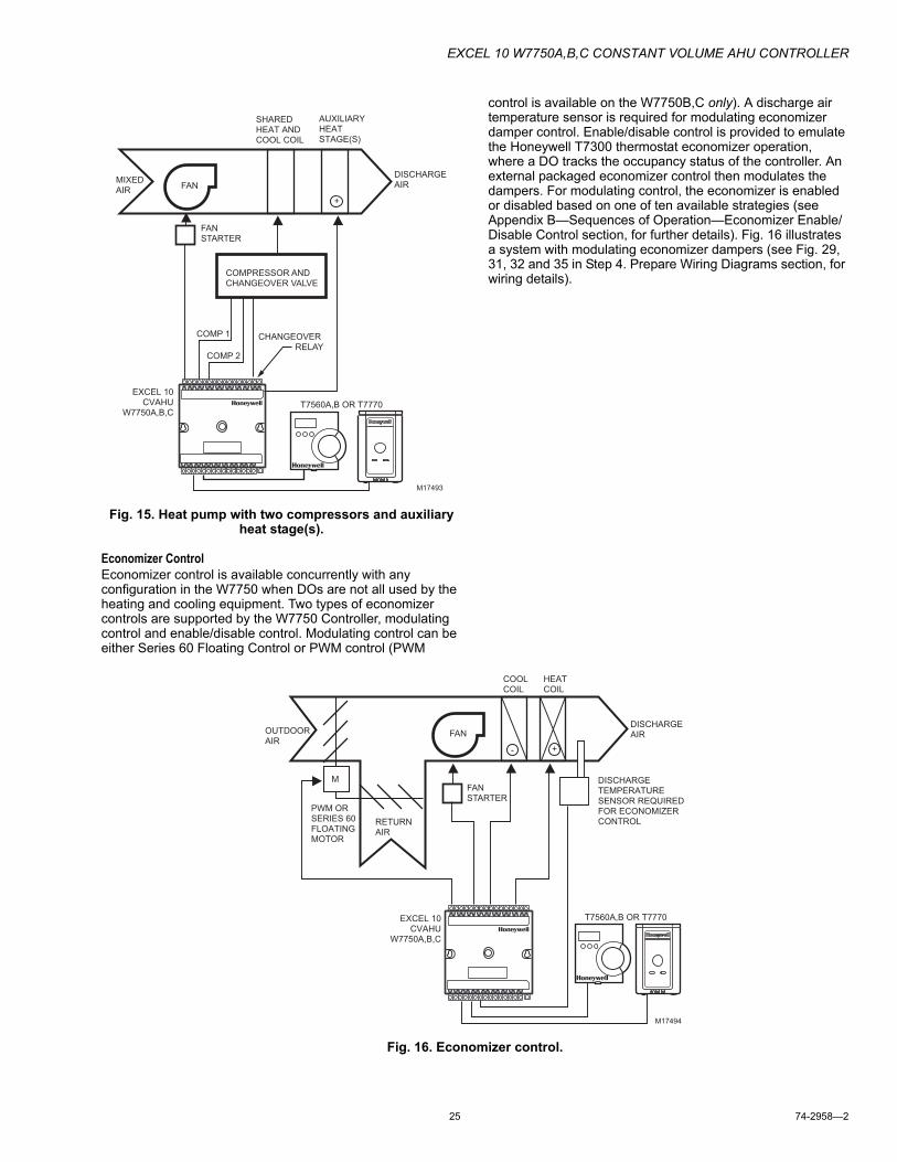
Fig. 15. Heat pump with two compressors and auxiliary heat stage(s).
Economizer ControlEconomizer control is available concurrently with any configuration in the W7750 when DOs are not all used by the heating and cooling equipment. Two types of economizer controls are supported by the W7750 Controller, modulating control and enable/disable control. Modulating control can be either Series 60 Floating Control or PWM control (PWM
control is available on the W7750B,C only). A discharge air temperature sensor is required for modulating economizer damper control. Enable/disable control is provided to emulate the Honeywell T7300 thermostat economizer operation, where a DO tracks the occupancy status of the controller. An external packaged economizer control then modulates the dampers. For modulating control, the economizer is enabled or disabled based on one of ten available strategies (see Appendix B�Sequences of Operation�Economizer Enable/Disable Control section, for further details). Fig. 16 illustrates a system with modulating economizer dampers (see Fig. 29, 31, 32 and 35 in Step 4. Prepare Wiring Diagrams section, for wiring details).
Fig. 16. Economizer control.
MIXEDAIR
AUXILIARYHEATSTAGE(S)
SHARED HEAT ANDCOOL COIL
DISCHARGEAIR
+
FAN
FANSTARTER
COMPRESSOR ANDCHANGEOVER VALVE
COMP 1
COMP 2
CHANGEOVER RELAY
M17493
EXCEL 10CVAHU
W7750A,B,CT7560A,B OR T7770
OUTDOORAIR
RETURNAIR
HEATCOIL
COOLCOIL
DISCHARGEAIR
- +
FAN
FANSTARTER
DISCHARGETEMPERATURESENSOR REQUIREDFOR ECONOMIZERCONTROL
M
PWM ORSERIES 60FLOATINGMOTOR
M17494
EXCEL 10CVAHU
W7750A,B,C
T7560A,B OR T7770

EXCEL 10 W7750A,B,C CONSTANT VOLUME AHU CONTROLLER
74-2958�2 26
Pneumatic Actuator ControlThe W7750B,C Controller can control pneumatic actuators for any or all of the three modulating outputs provided by the control algorithm (heat, cool and economizer). Control of pneumatic water/steam valves and damper actuators is provided through a transducer device using either Series 60 Floating Control or PWM DOs. A floating-to-pneumatic, or a PWM-to-pneumatic transducer is required for each output signal. The W7750A Controller can drive Series 60 Floating Control for only economizer control. There are no PWM outputs configurable on the W7750A model.
For projects with existing pneumatically actuated reheat valves, the Excel 10 W7750 Controller output must be converted to a pneumatic signal using a transducer device developed for use with Excel 10 Controllers. The transducer is available through Honeywell, or directly from a third party manufacturer.
Fig. 17 depicts a typical W7750 System with modulating heating valve using a pneumatic valve actuator. Also see Fig. 37 for wiring an RP7517B Pneumatic Transducer to a W7750C Controller.
NOTE: When choosing the pneumatic pressure range, make sure that the close-off pressure is 2 to 3 psi greater than that of the spring range. When using a spring range of 5 to 10 psi with 10 psi as the closed posi-tion, do not use a 0 to 10 psi model transducer; use a 0 to 20 psi transducer as the recommended selec-tion.
Fig. 17. Modulating heat with pneumatic valve actuator.
Mixed Output-type ControlThe W7750B,C Controller provides control for mixed-output-types of applications such as PWM heating and staged cooling control occurring simultaneously with Series 60 Floating Economizer Damper Control.
Occupancy SensorExcel 10 W7750 Controllers provide a digital input for connection to an occupancy sensor. This is a device, such as a passive infrared motion detector, that contains a dry contact
(see following NOTE) closure to indicate whether or not people are present in the space. The Excel 10 W7750 Controller expects a contact closure to indicate the space is Occupied. See Fig. 27 through 35 in Application Step 4, Prepare Wiring Diagrams, for details on wiring connections.
The control algorithm in the Excel 10 Controller uses the occupancy sensor, if configured, to determine the Effective Occupancy (see Table 5) mode of operation. If the Time Of Day (TOD) schedule indicates an Occupied state, and the occupancy sensor contact is closed, the Effective Occupancy mode is Occupied. However, if the TOD schedule indicates an Occupied state and the occupancy sensor contact is open, then the Effective Occupancy mode is STANDBY. The temperature control algorithm is then controlled to the STANDBY Cooling and Heating Setpoints.
If the occupancy sensor is not configured, a local controller can be put in the STANDBY mode only by either a one-to-one association of the occupancy sensor from another Excel 10 Controller to the local controller, or by receiving the STANDBY mode signal via the LONWORKS Bus.
NOTE: The Excel 10 Controller has limited power available (only 9 mA at 4.8 volts) for checking the digital inputs for contact closures. It is very important that the device used contains high quality, noncorroding con-tacts with resistivity that does not degrade; that is, increase over time. Use noble metal (such as gold or silver), or pimpled or sealed contacts to assure con-sistent, long-term operation.
Window Open/Closed Digital InputA digital input is also provided for detecting whether a window in the space was opened. The Excel 10 W7750 Controller can be connected to a dry contact (see the following NOTE and Fig. 27 through 35 in Application Step 4. Prepare Wiring Diagrams, for details) or a set of contacts wired in series (for monitoring multiple windows) to verify that the window(s) are closed. The algorithm expects a contact closure to indicate the window is closed. If an open window is detected, the algorithm changes the mode of operation to FREEZE_PROTECT, which shuts down the control functions, and watches for low space temperature conditions. The frost protection setpoint is 46.4°F (8°C), and the frost alarm occurs at 42.8°F (6°C).
NOTE: (This is the same NOTE as in the Occupancy Sensor section.) The Excel 10 has limited power available (only 9 mA at 4.8 volts) for checking the digital inputs for contact closures. It is very important that the device used contains high quality, noncorroding con-tacts with resistivity that does not degrade; that is, increase over time. Use noble metal (such as gold or silver), or pimpled or sealed contacts to assure con-sistent, long-term operation.
Wall Module OptionsAs previously discussed, there are four basic varieties of the T7770 Wall Modules and two of the T7560 Digital Wall Module (see the Product Names and the Construction sections). Also, a T7770 and T7560 Wall Modules can be shared among two or more W7750s. The control algorithm must be given this wall module information when configuring the W7750.
VALVE
PNEUMATIC
ACTUATOR
PNEUMATIC
TRANSDUCER
M
1
1
PNEUMATIC MAIN OR BRANCH LINE MUST BE 1/4 IN. (6 MM)
OR LARGER TUBING. A MINIMUM OF 6 FT (1.8M) OF TUBING
IS NEEDED IN A BRANCH LINE.
MIXED
AIR
HEAT
COIL
DISCHARGE
AIR
+
FAN
FAN
STARTER
M17495A
T7560A,B OR T7770
EXCEL 10 W7750A,B,C CONSTANT VOLUME AHU CONTROLLER
27 74-2958�2
Dirty Filter MonitorThe air filter in the air handler can be monitored by the W7750 and an alarm is issued when the filter media needs replacement. The two methods of monitoring the filter are:
1. Connecting a differential pressure switch to a digital input on the W7750A or W7750B,C.
2. Wiring a 2 to 10V differential pressure sensor (such as the P7640A,B 4-20 mA with 500 ohm resistor) to a voltage input on the W7750B,C. If the analog input sensor is used, its measured value 0 to 5 in. w.c. (0 to 1.25 kPa) is compared to a user-selectable setpoint [FltrPressStPt�valid range: 0 to 5 in. w.c. (0 to 1.25 kPa)], and the Dirty Filter alarm is issued when the pressure drop across the filter exceeds the setpoint.
Indoor Air Quality (IAQ) OverrideThe Excel 10 W7750 Controller provides IAQ ventilation control using one of two different methods of detecting poor air quality. The first is with an IAQ switch device connected to a digital input on the W7750 Controller, where a contact closure indicates poor air quality, and initiates the IAQ Override mode. The device can detect poor air quality using any desired measure such as CO2, VOC, CO, etc. The second method, which is only available on the W7750B,C, is through an analog input that connects to a CO2 sensor (0 to 10 Vdc, as provided with the C7232A,B). The measured value of CO2 from this sensor (0 to 2000 PPM) is compared to the setpoint (IAQSetpt). When the CO2 level is higher than the
setpoint (800 PPM adjustable), the IAQ Override is initiated. The IAQSetpt hysteresis is 50 PPM, IAQ Override is deactivated at a CO2 level less than 50 PPM below setpoint.
The effect of initiating the IAQ Override mode is that the economizer dampers are allowed to open above the standard minimum position setting to allow more fresh air to enter the building. See Appendix B�Sequences of Operation, for further control details.
Smoke ControlThe Excel 10 W7750 Controller supports smoke-related control strategies that are initiated either via a network command (DestEmergCmd) or from a local (physically connected) smoke detector digital input. The details of the W7750 smoke-related control operation are described in Appendix B�Sequences of Operation.
Freeze Stat (W7750B2011 or W7750C)A freeze stat can be monitored by the W7750 and issue a freeze stat alarm indicating the CVAHU is in danger of freezing its coil. The details of the W7750 freeze stat related control operation are described in Appendix B�Sequences of Operation.
Modes of OperationThe possible modes of operation for the W7750 Controller are listed in Table 5.
Table 5. Modes Of Operation For The Excel 10 W7750 Controller .Mode Description Events causing a controller to switch to this mode
Effective Occupancy (User Address: StatusOcc)OCCUPIED Controller is in Occupied mode Any of the following: Network input (DestSchedOcc) containing a
time-of-day schedule or a Time Clock DI, Occupancy Sensor DI; or from Network input (DestManMode) for manual override to OCC mode. DestManMode has the highest priority, followed by the Time Clock DI, and then DestSchedOcc.
STANDBY Controller is in Standby mode Either: (A) Network input (DestSchedOcc) containing a time-of-day schedule or other LONWORKS Bus node is STANDBY, or (B) Network input (DestSchedOcc) is OCCUPIED and the Occupancy Sensor DI is UNOCCUPIED.
UNOCCUPIED Controller is in Unoccupied mode Network input (DestSchedOcc) containing a time-of-day schedule or the network input DestManOcc has a value of UNOCCUPIED.
BYPASS OCCUPIED
Controller is in Occupied mode through a Bypass command
This mode is derived from the schedule occupancy (DestSchedOcc) having a state of UNOCCUPIED and a manual request for occupancy from one of three sources. Two of these are signals originated external to the unit, and received by DestManOcc and DestBypass. The third source for an occupancy request is from an override button located on a wall module. These three sources are arbitrated in a scheme determined by the configuration parameter (Network Wins or Last-in Wins from OvrdPriority).
Override Modes (User Address: StatusOvrd)OCCUPIED Controller occupancy mode was
overridden to Occupied modeNetwork input (DestManOcc) containing a time-of-day schedule override signal of OCCUPIED from another LONWORKS Bus device.
STANDBY Controller occupancy mode was overridden to Standby mode
Network input (DestManOcc) containing a time-of-day schedule override signal of STANDBY from another LONWORKS Bus device.
UNOCCUPIED Controller occupancy mode was overridden to Unoccupied mode
Network input (DestManOcc) containing a time-of-day schedule override signal of UNOCCUPIED from another LONWORKS Bus device.

EXCEL 10 W7750A,B,C CONSTANT VOLUME AHU CONTROLLER
74-2958�2 28
NOTE: During all modes all digital and analog physical inputs are periodically read, the diagnostic output network variables can be polled, the input network variables are received, and the output network variables are sent periodically.
APPLICATION STEPS
OverviewThe seven application steps shown in Table 6 are planning considerations for engineering an Excel 10 W7750 System. These steps are guidelines intended to aid understanding of the product I/O options, bus arrangement choices, configuration options and the Excel 10 W7750 Controller role in the overall LCBS/EXCEL 5000® OPEN� SYSTEM architecture.
Table 6. Application Steps.
BYPASS Controller occupancy mode was overridden to Bypass the current Unoccupied mode
DI (Bypass) was pressed, and the Bypass duration timer has not yet expired, or the network input DestManOcc has a value of BYPASS.
NOT ASSIGNED
No Bypass action No Override input received.
Operational Modes (User Address: StatusMode)START-UP AND WAIT
On power-up, provides a staggered start sequence to evenly apply the load to the electrical system.
This mode occurs on controller power-up, and after downloading to the controller from the configuration tool. Temperature control loops are disabled.
COOLING The Excel 10 is controlling the Cooling mode.
Space temperature has risen above the current cooling setpoint, or the network input (DestHvacMode) is COOL.
HEATING The Excel 10 is controlling the Heating mode.
Space temperature has fallen below the current heating setpoint, or the network input (DestHvacMode) is HEAT.
EMERGENCY HEAT
Compressors are disabled and only Auxiliary Heat stages are allowed to operate.
The network input (DestManHvacMode) is EMERG_HEAT.
OFF MODE The heat/cool control is turned off immediately. The node is not running its normal temperature control.
Network input (DestManMode) containing AHU operational mode information from C-Bus has value of MORNING WARM-UP.
DISABLED MODE
The heat/cool control and frost protection are turned off immediately. The node is not running its normal temperature control.
�
SMOKE EMERGENCY
The node has entered a smoke emergency. The fan and dampers are then set to the conditions configured by SmkCtlMode. The control remains in SMOKE_ EMERGENCY until power is cycled or the node receives DestEmergCmd set to EMERG_NORMAL.
Network input (DestEmergCmd) containing smoke control signal from another LONWORKS Bus device has value of SMOKE_EMERG.
FREEZE PROTECT
The temperature control is set to HEAT with the setpoint set to the frost limit setpoint 46.4°F (8°C).
The Window digital input detects an open window.
MANUAL POSITION
The physical outputs are being controlled manually. The temperature control loop is turned off.
Typically this is done by the user through LONSPEC� setting the point DestManMode to MANUAL mode.
FAN ONLY Control algorithm is disabled, except that the fan is turned on.
The space temperature sensor has failed, or the network input (DestHvacMode) is FAN ONLY.
DISABLED Control algorithm is shut off. Network input (DestManMode) containing AHU operational mode information from an operator or the network that has a value of DISABLED.
Table 5. Modes Of Operation For The Excel 10 W7750 Controller (Continued).Mode Description Events causing a controller to switch to this mode
Step No. Description1 Plan The System2 Determine Other Bus Devices Required3 Lay Out Communications and Power Wiring

EXCEL 10 W7750A,B,C CONSTANT VOLUME AHU CONTROLLER
29 74-2958�2
Step 1. Plan the SystemPlan the use of the W7750 Controllers according to the job requirements. Determine the location, functionality and sensor or actuator usage. Verify the sales estimate of the number of W7750 Controllers, T7770 and T7560 Wall Modules required for each model type. Also check the number and type of output actuators and other required accessories.
When planning the system layout, consider potential expansion possibilities to allow for future growth. Planning is very important to be prepared for adding HVAC systems and controllers in future projects.
T7560 Wall Modules can only be hard-wired, they have no LONWORKS Bus access. T7770 Wall Modules can be installed as either hard-wired I/O-only devices or additional wiring can be run to them (for the LONWORKS Bus network) to allow a LONSPEC� or Care user access to the LONWORKS Bus. The application engineer needs to determine how many wall modules, T7770s and T7560s are required. All T7770 Wall Modules, except the T7770A1006, can be connected via the LONWORKS Bus jack. Also the application engineer needs to know how many T7770s without LONWORKS Bus network connections are being installed on the job, and then clearly document which wall modules (if any) have network access. This information is required during installation to ensure that the proper number and type of wires are pulled to the wall modules, and the building operators are informed about where they can plug in to the LONWORKS Bus network with a portable operator terminal (see Fig. 18, 19 and 20). Refer to Step 4. Prepare Wiring Diagrams for details, about the about the wiring differences between the two types.
The FTT communication wiring, (LONWORKS Bus) between controllers is a free topology scheme that supports T-tap, star, loop, and mixed wiring architecture. Refer to the LONWORKS Bus Wiring Guidelines form, 74-2865 for complete description of network topology rules. See Application Step 3. Lay Out Communications and Power Wiring, for more information on bus wiring layout, and see Fig. 27 through 35 in Application Step 4. Prepare Wiring Diagrams, for wiring details.
Fig. 18. Connecting the portable operator terminal to the LONWORKS® Bus.
The application engineer must review the Direct Digital Control (DDC) job requirements. This includes the Sequences of Operation for the W7750 units, and for the system as a whole. Usually there are variables that must be passed between the W7750 Controllers and other zone controller(s), or central plant controller(s) that are required for optimum system-wide operation. Typical examples are the TOD Occ/Unocc signal, the outdoor air temperature, the demand limit control signal, and the smoke control mode signal.
It is important to understand these interrelationships early in the job engineering process to ensure implementation when configuring the controllers. (See Application Step 6. Configure Controllers, for information on the various Excel 10 parameters and on Excel 10 point mapping.)
Step 2. Determine Other Bus Devices RequiredA maximum of 62 nodes can communicate on a single LONWORKS Bus segment. Each W7750 (CVAHU) Controller constitutes one node. If more nodes are required, a Q7740A1008 Two-way Repeater, a Q7740B1006 Four-way Repeater, or a Q7751A,B Router is necessary. Using a router allows up to 125 nodes, divided between two LONWORKS Bus segments. The router accounts for two of these nodes (one node on each side of the router); an XL5000 Q7750A Excel 10 Zone Manager takes one node and two nodes are available for operator terminal nodes, leaving 120 nodes available for Excel 10/15 Controllers. All 120 controllers are able to talk to each other through the repeater/router.
Each LONWORKS Bus segment is set up with two unused nodes to allow for a LONSPEC�/LONSTATION� or CARE operator terminal to be connected to the LONWORKS Bus. Multiple CARE terminals (for XL5000 system), or one LonSpec and one LonStation (for LCBS systems) can be connected to the LONWORKS Bus at the same time. Table 7 summarizes the LONWORKS Bus segment configuration rules.
4 Prepare Wiring Diagrams5 Order Equipment6 Configure Controllers7 Troubleshooting
Step No. Description
M15120B
NOTEBOOK PC
LONWORKS BUS
PORT
EIA-232
SERIAL
PORT
LCBS/
Q7760A SLTA
CABLE
PART
NO. 205979
SHIELDED
INTERFACE
CABLE
EXCEL 10
W7750
CVAHU
CONTROLLER

EXCEL 10 W7750A,B,C CONSTANT VOLUME AHU CONTROLLER
74-2958�2 30
Table 7. LONWORKS® Bus Configuration Rules and Device Node Numbers.
Refer to the LONWORKS Bus Wiring Guidelines form, 74-2865 for complete description of network topology rules and the maximum wire length limitations. If longer runs are required, a Q7740A 2-Way or Q7740B 4-Way Repeater can be added to extend the length of the LONWORKS Bus. A Q7751A,B Router can be added to partition the system into two segments and effectively double the length of the LONWORKS Bus. Only one router is allowed with each Excel 10 Zone Manager, and each network segment can have a maximum of one repeater.
NOTE: LCBS does not support a router unless it is config-ured as a repeater.
In addition, all LONWORKS Bus segments require the installation of a 209541B Termination Module for a singly terminated LONWORKS Bus or two 209541B Termination Modules for a doubly terminated LONWORKS Bus. For more details on LONWORKS Bus termination, refer to the LONWORKS Bus Wiring Guidelines form, 74-2865, or see Application Step 3. Lay Out Communications and Power Wiring, and the LONWORKS Bus Termination Module subsection in Application Step 4.
Step 3. Lay Out Communications and Power Wiring
LONWORKS® Bus LayoutThe communications bus, LONWORKS Bus, is a 78-kilobits per second (kbps) serial link that uses transformer isolation and differential Manchester encoding. Approved cable types for
LONWORKS Bus communications wiring is Level IV 22 AWG (0.34 mm2) plenum or non-plenum rated unshielded, twisted pair, solid conductor wire. For nonplenum areas, use Level IV 22 AWG (0.325 mm2), such as U.S. part AK3781 (one pair) or U.S. part AK3782 (two pair). In plenum areas, use plenum-rated Level IV, 22 AWG (0.325 mm2) such as U.S. part AK3791 (one pair) or U.S. part AK3792 (two pair). See Tables 9 and 11 for part numbers. Contact Echelon Corp. Technical Support for the recommended vendors of Echelon approved cables. The FTT communications bus, LONWORKS Bus, supports a polarity insensitive, free topology wiring scheme that supports T-tap, star, loop, and mixed bus wiring.
LONWORKS Bus networks can be configured in a variety of ways, so refer to the LONWORKS Bus Wiring Guidelines form, 74-2865 for complete description of network topology rules and Table 7. Fig. 19 and 20 depict two typical LONWORKS Bus network topologies; One has only one doubly terminated LONWORKS Bus segment that has 60 nodes or less, and one showing two singly terminated LONWORKS Bus segments that has 120 nodes or less (60 MAX per each segment). The bus configuration is set up using the Network Manager tool from within LONSPEC� or CARE.
NOTE: For wiring details see the LONWORKS Bus Termination Module subsection in Step 4. For wall module wiring, U.S. part AK3782 (non-plenum) or U.S. part AK3792 (plenum) can be used. For a LONWORKS Bus that is a doubly terminated daisy-chain, these cables contain two twisted pairs (one for the run down to the wall module, and one for the run back up to the controller) for ease of installation.
One LONWORKS Bus Segment Example Maximum Number of Nodes Equals 62One Q7750A Excel 10 Zone Manager 1 node
Port for operator terminal access (LONSPEC� or CARE) 1 nodeMaximum number of Excel 10/15s 60 nodes (Excel 15s supported by LCBS only)
Total 62 nodes
Two LONWORKS Bus Segments Example Maximum Number of Nodes Equals 125One Q7750A Excel 10 Zone Manager 1 node (supported on XL5000 only)
One Q7751A,B Router 2 nodes (1 in each Bus Segment); Repeaters do not have nodesPorts for operator terminal access: two CARE terminals,
or one LONSPEC� and one LONSTATION� terminal2 nodes (1 in each Bus Segment)
Maximum number of Excel 10/15s in segment number one 60 nodes (Excel 15s supported by LCBS only)Maximum number of Excel 10/15s in segment number two 60 nodes (Excel 15s supported by LCBS only)
Total 125 nodes

EXCEL 10 W7750A,B,C CONSTANT VOLUME AHU CONTROLLER
31 74-2958�2
Fig. 19. Wiring layout for one doubly terminated daisy-chain LONWORKS® Bus segment.
NOTE: See the LONWORKS Bus Termination Module section for wiring details.
IMPORTANTNotes on communications wiring:� All field wiring must conform to local codes and
ordinances or as specified on installation wiring diagrams.
� Approved cable types for LONWORKS Bus communi-cations wiring is Level IV 22 AWG (0.34 mm2) plenum or non-plenum rated unshielded, twisted pair, solid conductor wire. For nonplenum areas, use Level IV 22 AWG (0.34 mm2), such as U.S. part AK3781 (one pair) or U.S. part AK3782 (two pair). In plenum areas, use plenum-rated Level IV, 22 AWG (0.34 mm2) such as U.S. part AK3791 (one pair) or U.S. part AK3792 (two pair). See Tables 9 and 11 for part numbers. Contact Echelon Corp. Technical Support for the recommended vendors of Echelon approved cables.
� Unswitched 24 Vac power wiring can be run in the same conduit as the LONWORKS Bus cable.
� Do not use different wire types or gauges on the same LONWORKS Bus segment. The step change in line impedance characteristics causes unpredictable reflections on the bus. When using different types is unavoidable, use a Q7751A,B Router at the junction.
� In noisy (high EMI) environments, avoid wire runs parallel to noisy power cables, or lines containing lighting dimmer switches, and keep at least 3 in. (76 mm) of separation between noisy lines and the LONWORKS Bus cable.
� Make sure that neither of the LONWORKS Bus wires is grounded.
M22743
EXCEL 10
VAV
EXCEL 10
VAV
EXCEL 10
CVAHU
EXCEL 10
CVAHU
EXCEL 10
CVAHU
EXCEL 10
CVAHU
EXCEL 10
VAV
EXCEL 10
VAV
EXCEL 10
VAV
LONWORKS BUS
LONWORKS BUS
LO
NW
OR
KS
BU
S
UP TO 60
TOTAL NODES
T7770T7770
T7770
T7770
JACK FOR
OPERATOR
TERMINAL
209541B
TERMINATION MODULES
(AT ENDS OF
LONWORKS BUS
DAISY-CHAIN)
T7770s
WITH
NO
LONWORKS BUS
ACCESS
LONWORKS BUS
I/O CONNECTIONS
EXCEL 10
CVAHU
EXCEL 10
CVAHU
T7770 OR T7560A,B
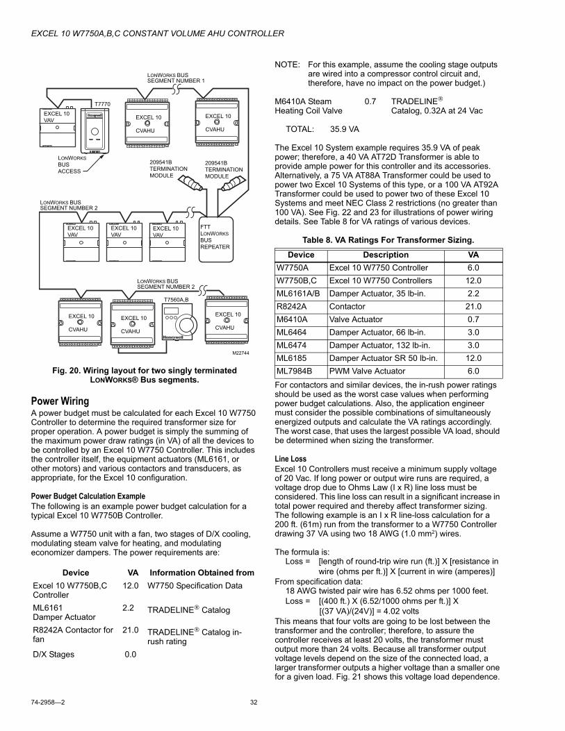
EXCEL 10 W7750A,B,C CONSTANT VOLUME AHU CONTROLLER
74-2958�2 32
Fig. 20. Wiring layout for two singly terminated LONWORKS® Bus segments.
Power WiringA power budget must be calculated for each Excel 10 W7750 Controller to determine the required transformer size for proper operation. A power budget is simply the summing of the maximum power draw ratings (in VA) of all the devices to be controlled by an Excel 10 W7750 Controller. This includes the controller itself, the equipment actuators (ML6161, or other motors) and various contactors and transducers, as appropriate, for the Excel 10 configuration.
Power Budget Calculation ExampleThe following is an example power budget calculation for a typical Excel 10 W7750B Controller.
Assume a W7750 unit with a fan, two stages of D/X cooling, modulating steam valve for heating, and modulating economizer dampers. The power requirements are:
NOTE: For this example, assume the cooling stage outputs are wired into a compressor control circuit and, therefore, have no impact on the power budget.)
M6410A Steam 0.7 TRADELINE®
Heating Coil Valve Catalog, 0.32A at 24 Vac
TOTAL: 35.9 VA
The Excel 10 System example requires 35.9 VA of peak power; therefore, a 40 VA AT72D Transformer is able to provide ample power for this controller and its accessories. Alternatively, a 75 VA AT88A Transformer could be used to power two Excel 10 Systems of this type, or a 100 VA AT92A Transformer could be used to power two of these Excel 10 Systems and meet NEC Class 2 restrictions (no greater than 100 VA). See Fig. 22 and 23 for illustrations of power wiring details. See Table 8 for VA ratings of various devices.
Table 8. VA Ratings For Transformer Sizing.
For contactors and similar devices, the in-rush power ratings should be used as the worst case values when performing power budget calculations. Also, the application engineer must consider the possible combinations of simultaneously energized outputs and calculate the VA ratings accordingly. The worst case, that uses the largest possible VA load, should be determined when sizing the transformer.
Line LossExcel 10 Controllers must receive a minimum supply voltage of 20 Vac. If long power or output wire runs are required, a voltage drop due to Ohms Law (I x R) line loss must be considered. This line loss can result in a significant increase in total power required and thereby affect transformer sizing. The following example is an I x R line-loss calculation for a 200 ft. (61m) run from the transformer to a W7750 Controller drawing 37 VA using two 18 AWG (1.0 mm2) wires.
The formula is:Loss = [length of round-trip wire run (ft.)] X [resistance in
wire (ohms per ft.)] X [current in wire (amperes)]From specification data:
18 AWG twisted pair wire has 6.52 ohms per 1000 feet.Loss = [(400 ft.) X (6.52/1000 ohms per ft.)] X
[(37 VA)/(24V)] = 4.02 voltsThis means that four volts are going to be lost between the transformer and the controller; therefore, to assure the controller receives at least 20 volts, the transformer must output more than 24 volts. Because all transformer output voltage levels depend on the size of the connected load, a larger transformer outputs a higher voltage than a smaller one for a given load. Fig. 21 shows this voltage load dependence.
Device VA Information Obtained fromExcel 10 W7750B,C Controller
12.0 W7750 Specification Data
ML6161 Damper Actuator
2.2 TRADELINE® Catalog
R8242A Contactor for fan
21.0 TRADELINE® Catalog in-rush rating
D/X Stages 0.0
EXCEL 10
VAV
EXCEL 10
VAV
EXCEL 10
VAV
LONWORKS BUS
SEGMENT NUMBER 2
LONWORKS BUS
SEGMENT NUMBER 1
LONWORKS BUS
SEGMENT NUMBER 2
T7770
LONWORKS
BUS
ACCESS
FTT
LONWORKS
BUS
REPEATER
EXCEL 10
VAV
209541B
TERMINATION
MODULE
209541B
TERMINATION
MODULE
M22744
EXCEL 10
CVAHU
EXCEL 10
CVAHU
EXCEL 10
CVAHU
EXCEL 10
CVAHU
EXCEL 10
CVAHU
T7560A,B
Device Description VAW7750A Excel 10 W7750 Controller 6.0W7750B,C Excel 10 W7750 Controllers 12.0ML6161A/B Damper Actuator, 35 lb-in. 2.2R8242A Contactor 21.0M6410A Valve Actuator 0.7ML6464 Damper Actuator, 66 lb-in. 3.0ML6474 Damper Actuator, 132 lb-in. 3.0ML6185 Damper Actuator SR 50 lb-in. 12.0ML7984B PWM Valve Actuator 6.0

EXCEL 10 W7750A,B,C CONSTANT VOLUME AHU CONTROLLER
33 74-2958�2
In the preceding I x R loss example, even though the controller load is only 37 VA, a standard 40 VA transformer is not sufficient due to the line loss. From Fig. 21, a 40 VA transformer is just under 100 percent loaded (for the 37 VA controller) and, therefore, has a secondary voltage of 22.9 volts. (Use the lower edge of the shaded zone in Fig. 21 that represents the worst case conditions.) When the I x R loss of four volts is subtracted, only 18.9 volts reaches the controller, which is not enough voltage for proper operation.
In this situation, the engineer basically has three alternatives:1. Use a larger transformer; for example, if an 80 VA
model is used, see Fig. 21, an output of 24.4 volts minus the four volt line loss supplies 20.4V to the controller. Although acceptable, the four-volt line-loss in this example is higher than recommended. See the following IMPORTANT.
2. Use heavier gauge wire for the power run. 14 AWG (2.0 mm2) wire has a resistance of 2.57 ohms per 1000 ft. which, using the preceding formula, gives a line-loss of only 1.58 volts (compared with 4.02 volts). This would allow a 40 VA transformer to be used. 14 AWG (2.0 mm2) wire is the recommended wire size for 24 Vac wiring.
3. Locate the transformer closer to the controller, thereby reducing the length of the wire run, and the line loss. The issue of line-loss is also important in the case of the output wiring connected to the Triac digital outputs. The same formula and method are used. The rule to remember is to keep all power and output wire runs as short as practical. When necessary, use heavier gauge wire, a bigger transformer, or install the transformer closer to the controller.
IMPORTANTNo installation should be designed where the line loss is greater than two volts to allow for nominal operation if the primary voltage drops to 102 Vac (120 Vac minus 15 percent).
To meet the National Electrical Manufacturers Association (NEMA) standards, a transformer must stay within the NEMA limits. The chart in Fig. 21 shows the required limits at various loads.
With 100 percent load, the transformer secondary must supply between 23 and 25 volts to meet the NEMA standard. When a purchased transformer meets the NEMA standard DC20-1986, the transformer voltage-regulating ability can be considered reliable. Compliance with the NEMA standard is voluntary.
The following Honeywell transformers meet this NEMA standard:
Fig. 21. NEMA class 2 transformer voltage output limits.
Attach earth ground to W7750 Controller terminal 1. See Fig. 22, 23, 24, and 27 through 35.
Fig. 22. Power wiring details for one Excel 10 per transformer.
See Fig. 23. for wiring more than one Excel 10 per transformer.
Transformer Type VA RatingAT20A 20
AT40A 40AT72D 40AT87A 50AK3310 Assembly 100
Transformer Type VA Rating
27
26
25
24
23
22
21
20
19
18
17
16
15
14
0 50 100 150
% OF LOAD
SE
CO
ND
AR
Y V
OL
TA
GE
200
M993
M10089B
CONNECT POWER TO TERMINALS 24 AND 25
TRIAC LINESTO ACTUATORSAND CONTACTORS
TRANSFORMER
W7750B,C
EARTHGROUND
20222425
1
OUTPUTDEVICEPOWER

EXCEL 10 W7750A,B,C CONSTANT VOLUME AHU CONTROLLER
74-2958�2 34
Fig. 23. Power wiring details for two or more Excel 10s per transformer.
IMPORTANTIf the W7750 Controller is used on Heating and Cooling Equipment (UL 1995 U.S. only) devices and the transformer primary power is more than 150 volts, connect the transformer secondary to earth ground, see Fig. 24.
Fig. 24. Transformer power wiring details for one Excel 10 used in UL 1995 equipment (U.S. only).
IMPORTANTNotes on power wiring:
� All field wiring must conform to local codes and ordi-nances or as specified on installation wiring dia-grams.
� To maintain NEC Class 2 and UL ratings, the installa-tion must use transformers of 100 VA or less capac-ity.
� For multiple controllers operating from a single trans-former, the same side of the transformer secondary must be connected to the same input terminal in each controller (21 on the W7750A and 24 on the W7750B,C) and the ground terminals must be con-nected to a verified earth ground for each controller in the group. See Fig. 23. (Controller configurations are not necessarily limited to three devices per trans-former.)
� For the W7750B,C Controller (which has Triac out-puts), all output devices must be powered from the same transformer as the one powering the Excel 10 W7750 Controller.
� Use the heaviest gauge wire available, up to 14 AWG (2.0 mm2) with a minimum of 18 AWG (1.0 mm2) for all power and earth ground connections.
� To minimize EMI noise, do not run Triac output wires in the same conduit as the input wires or the LON-WORKS Bus communications wiring.
� Unswitched 24 Vac power wiring can be run in the same conduit as the LONWORKS Bus cable.
� Make earth ground connections with the shortest possible wire run using 14 AWG (2.0 mm2) wire. A good earth ground is essential for W7750 operation. Ideally, connect the earth ground to the ground bus at a motor control center or circuit breaker panel. However, if the nearest ideal earth ground is inac-cessible, consider an alternate source for earth ground. Metal water pipe is generally a good ground, but do not use sprinkler pipe if prohibited by local codes. Attention must be given when duct work, con-duit, or rebar are to be considered as ground sources. It is the responsibility of the installer to assure that these structures are tied back to a known earth ground.
M10090A
24 VAC120/240 VAC
TRANSFORMER
W7750B,C
EARTHGROUND
2425
1
W7750B,C
EARTHGROUND
2425
1
W7750B,C
EARTHGROUND
2425
1
M10088A
24 VAC
LINE VOLTAGEGREATERTHAN 150 VAC
TRANSFORMER
W7750
EARTHGROUND
EARTHGROUND
IF THE W7750 CONTROLLER IS USED IN UL 1995 EQUIPMENT AND THE PRIMARY POWER IS MORE THAN 150 VOLTS, GROUND 24 VAC COM SIDE OF TRANSFORMER SECONDARY.
1
1
1
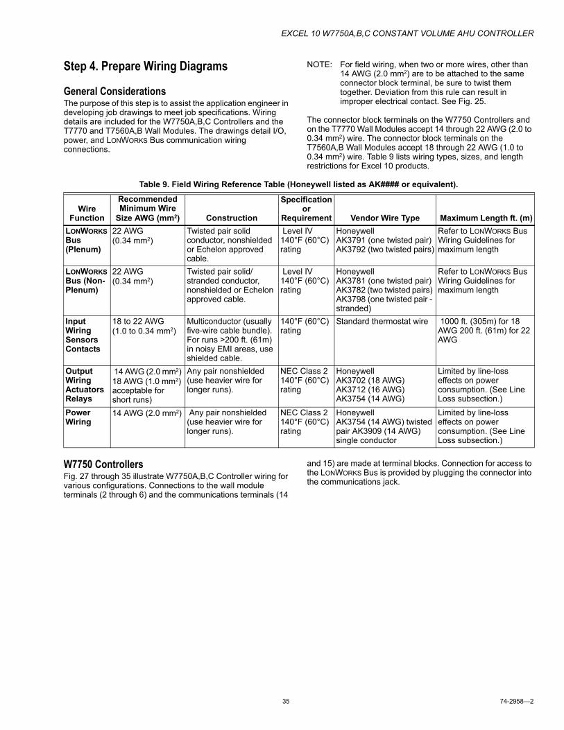
EXCEL 10 W7750A,B,C CONSTANT VOLUME AHU CONTROLLER
35 74-2958�2
Step 4. Prepare Wiring Diagrams
General ConsiderationsThe purpose of this step is to assist the application engineer in developing job drawings to meet job specifications. Wiring details are included for the W7750A,B,C Controllers and the T7770 and T7560A,B Wall Modules. The drawings detail I/O, power, and LONWORKS Bus communication wiring connections.
NOTE: For field wiring, when two or more wires, other than 14 AWG (2.0 mm2) are to be attached to the same connector block terminal, be sure to twist them together. Deviation from this rule can result in improper electrical contact. See Fig. 25.
The connector block terminals on the W7750 Controllers and on the T7770 Wall Modules accept 14 through 22 AWG (2.0 to 0.34 mm2) wire. The connector block terminals on the T7560A,B Wall Modules accept 18 through 22 AWG (1.0 to 0.34 mm2) wire. Table 9 lists wiring types, sizes, and length restrictions for Excel 10 products.
Table 9. Field Wiring Reference Table (Honeywell listed as AK#### or equivalent).
W7750 ControllersFig. 27 through 35 illustrate W7750A,B,C Controller wiring for various configurations. Connections to the wall module terminals (2 through 6) and the communications terminals (14
and 15) are made at terminal blocks. Connection for access to the LONWORKS Bus is provided by plugging the connector into the communications jack.
Wire Function
Recommended Minimum Wire
Size AWG (mm2) Construction
Specification or
Requirement Vendor Wire Type Maximum Length ft. (m)LONWORKS Bus (Plenum)
22 AWG (0.34 mm2)
Twisted pair solid conductor, nonshielded or Echelon approved cable.
Level IV 140°F (60°C) rating
HoneywellAK3791 (one twisted pair) AK3792 (two twisted pairs)
Refer to LONWORKS Bus Wiring Guidelines for maximum length
LONWORKS Bus (Non-Plenum)
22 AWG (0.34 mm2)
Twisted pair solid/stranded conductor, nonshielded or Echelon approved cable.
Level IV 140°F (60°C) rating
HoneywellAK3781 (one twisted pair) AK3782 (two twisted pairs) AK3798 (one twisted pair - stranded)
Refer to LONWORKS Bus Wiring Guidelines for maximum length
Input Wiring Sensors Contacts
18 to 22 AWG (1.0 to 0.34 mm2)
Multiconductor (usually five-wire cable bundle). For runs >200 ft. (61m) in noisy EMI areas, use shielded cable.
140°F (60°C) rating
Standard thermostat wire 1000 ft. (305m) for 18 AWG 200 ft. (61m) for 22 AWG
Output Wiring Actuators Relays
14 AWG (2.0 mm2) 18 AWG (1.0 mm2) acceptable for short runs)
Any pair nonshielded (use heavier wire for longer runs).
NEC Class 2 140°F (60°C) rating
HoneywellAK3702 (18 AWG) AK3712 (16 AWG) AK3754 (14 AWG)
Limited by line-loss effects on power consumption. (See Line Loss subsection.)
Power Wiring
14 AWG (2.0 mm2) Any pair nonshielded (use heavier wire for longer runs).
NEC Class 2 140°F (60°C) rating
HoneywellAK3754 (14 AWG) twisted pair AK3909 (14 AWG) single conductor
Limited by line-loss effects on power consumption. (See Line Loss subsection.)

EXCEL 10 W7750A,B,C CONSTANT VOLUME AHU CONTROLLER
74-2958�2 36
Fig. 25. Attaching two or more wires at terminal blocks.
The W7750B provides a jumper to select High-Side or Low-Side switching of the digital outputs. Fig. 26 shows the W7750B High-Side/Low-Side selectable switching. (See wiring diagrams, Fig. 30 through 34.)
Fig. 26. W7750B High-Side/Low-Side selectable switching and jumper location (on W7750B2011 and W7750C).
NOTE: If an Excel 10 W7750A,B,C Controller is not connected to a good earth ground, the controller internal transient protection circuitry is compromised and the function of protecting the controller from noise and power line spikes cannot be fulfilled. This can result in a damaged circuit board and require replacing the controller.
See Table 10 for a description of the W7750A terminals.
1/2(13)
STRIP 1/2 IN. (13 MM) FROM WIRES TO BE ATTACHED AT ONE TERMINAL.
1.
2. TWIST WIRES TOGETHER WITH PLIERS (A MINIMUM OF THREE TURNS).
3. CUT TWISTED END OF WIRES TO 3/16 IN. (5 MM) BEFORE INSERTING INTO TERMINAL AND TIGHTENING SCREW. THEN PULL ON EACH WIRE IN ALL TERMINALS TO CHECK FOR GOOD MECHANICAL CONNECTION. M17207
U3
Q4
J2
JUMPER
TERMINAL 24
J2 IS LOCATED NEAR TERMINAL 24 (COVER REMOVED).
W7750B IS FACTORY-DELIVERED WITH JUMPER ON HIGH-SIDE (PINS CLOSEST TO TERMINAL BLOCK). LOW-SIDE PINS ARE TWO PINS CLOSEST TO Q4.
1
1
2
2
M16418A
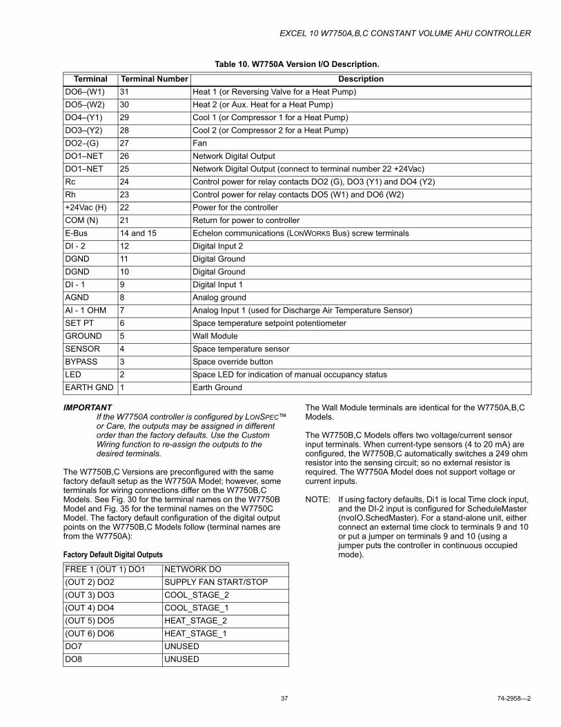
EXCEL 10 W7750A,B,C CONSTANT VOLUME AHU CONTROLLER
37 74-2958�2
Table 10. W7750A Version I/O Description.
IMPORTANTIf the W7750A controller is configured by LONSPEC� or Care, the outputs may be assigned in different order than the factory defaults. Use the Custom Wiring function to re-assign the outputs to the desired terminals.
The W7750B,C Versions are preconfigured with the same factory default setup as the W7750A Model; however, some terminals for wiring connections differ on the W7750B,C Models. See Fig. 30 for the terminal names on the W7750B Model and Fig. 35 for the terminal names on the W7750C Model. The factory default configuration of the digital output points on the W7750B,C Models follow (terminal names are from the W7750A):
Factory Default Digital Outputs
The Wall Module terminals are identical for the W7750A,B,C Models.
The W7750B,C Models offers two voltage/current sensor input terminals. When current-type sensors (4 to 20 mA) are configured, the W7750B,C automatically switches a 249 ohm resistor into the sensing circuit; so no external resistor is required. The W7750A Model does not support voltage or current inputs.
NOTE: If using factory defaults, Di1 is local Time clock input, and the DI-2 input is configured for ScheduleMaster (nvoIO.SchedMaster). For a stand-alone unit, either connect an external time clock to terminals 9 and 10 or put a jumper on terminals 9 and 10 (using a jumper puts the controller in continuous occupied mode).
Terminal Terminal Number DescriptionDO6�(W1) 31 Heat 1 (or Reversing Valve for a Heat Pump)DO5�(W2) 30 Heat 2 (or Aux. Heat for a Heat Pump)DO4�(Y1) 29 Cool 1 (or Compressor 1 for a Heat Pump)DO3�(Y2) 28 Cool 2 (or Compressor 2 for a Heat Pump)DO2�(G) 27 FanDO1�NET 26 Network Digital OutputDO1�NET 25 Network Digital Output (connect to terminal number 22 +24Vac)Rc 24 Control power for relay contacts DO2 (G), DO3 (Y1) and DO4 (Y2) Rh 23 Control power for relay contacts DO5 (W1) and DO6 (W2)+24Vac (H) 22 Power for the controllerCOM (N) 21 Return for power to controllerE-Bus 14 and 15 Echelon communications (LONWORKS Bus) screw terminalsDI - 2 12 Digital Input 2DGND 11 Digital GroundDGND 10 Digital GroundDI - 1 9 Digital Input 1AGND 8 Analog groundAI - 1 OHM 7 Analog Input 1 (used for Discharge Air Temperature Sensor)SET PT 6 Space temperature setpoint potentiometerGROUND 5 Wall ModuleSENSOR 4 Space temperature sensorBYPASS 3 Space override buttonLED 2 Space LED for indication of manual occupancy statusEARTH GND 1 Earth Ground
FREE 1 (OUT 1) DO1 NETWORK DO(OUT 2) DO2 SUPPLY FAN START/STOP(OUT 3) DO3 COOL_STAGE_2(OUT 4) DO4 COOL_STAGE_1(OUT 5) DO5 HEAT_STAGE_2(OUT 6) DO6 HEAT_STAGE_1DO7 UNUSEDDO8 UNUSED

EXCEL 10 W7750A,B,C CONSTANT VOLUME AHU CONTROLLER
74-2958�2 38
Fig. 27. Typical W7750A Controller AHU application wiring. (For more information on note 2, refer to Fig. 25.)
Fig. 28. Typical W7750A Controller with separate transformer application wiring.
(For more information on note 2, refer to Fig. 25.)
1 2 3 4 5 6 7 8
1
3
2
2
1
2
3
EARTH GROUND WIRE LENGTH SHOULD BE HELD TO A MINIMUM.USE THE HEAVIEST GAUGE WIRE AVAILABLE, UP TO 14 AWG (2.O MM2) WITH A MINIMUM OF 18 AWG (1.O MM2), FOR EARTH GROUND WIRE.
TO ASSURE PROPER ELECTRICAL CONTACT, WIRES MUST BE TWISTEDTOGETHER BEFORE INSERTION INTO THE TERMINAL BLOCK.
LOAD POWER WIRE CAN BE CONNECTED TO TERMINAL 22.
LO
NW
OR
KS-B
US
EA
RT
HG
RO
UN
D
JACK FOR LONWORKS-BUS NETWORKACCESS
7 6 5 4 3 2 1
T7770C
WALL
MODULE
SE
T P
T
GN
D
SE
NS
OR
BY
PA
SS
LE
D
E-B
US
E-B
US
9 10 11 12 14 J315
31 30 29 28 27 26 25 24 23 22 21 20
WALL MODULE
SE
T P
T
AI
GR
OU
ND
AI
GR
OU
ND
DI
GR
OU
ND
DI
GR
OU
ND
SE
NS
OR
BY
PA
SS
LE
D
LO
N
JA
CK
LO
NW
OR
KS
BU
S
NO
T U
SE
D
9 8
19 18 17 16
AI-
1 O
HM
DI-
1
DI-
2
13
TIME CLOCK
M10085C
DISCHARGE AIR TEMP
24
VA
C
24
VA
C C
OM
Rc
Rh
W1
W2
Y1
Y2 G NOT USED
24 VAC
+
-
LOAD AND CONTROLLERPOWERFAN
COMP2COMP 1HEAT 2HEAT 1
W7750A
CONSTANT
VOLUME AHU
CONTROLLER
NE
TW
OR
KD
O
1 2 3 4 5 6 7 8
W7750A
CONSTANT
VOLUME AHU
CONTROLLER
1
2
2
1
2
EARTH GROUND WIRE LENGTH SHOULD BE HELD TO A MINIMUM.USE THE HEAVIEST GAUGE WIRE AVAILABLE, UP TO 14 AWG (2.O MM2) WITH A MINIMUM OF 18 AWG (1.O MM2), FOR EARTH GROUND WIRE.
TO ASSURE PROPER ELECTRICAL CONTACT, WIRES MUST BE TWISTEDTOGETHER BEFORE INSERTION INTO THE TERMINAL BLOCK.
LO
NW
OR
KS-B
US
EA
RT
HG
RO
UN
D
JACK FOR LONWORKS-BUS NETWORKACCESS
7 69 8 5 4 3 2 1
T7770C
WALL
MODULE
SE
T P
T
GN
D
SE
NS
OR
BY
PA
SS
LE
D
E-B
US
E-B
US
9 10 11 12 14 J315
31 30 29 28 27 26 25 24 23 22 21 20
WALL MODULE
SE
T P
T
SE
NS
OR
BY
PA
SS
LE
D
NO
T U
SE
D
19 18 17 16
AI-
1 O
HM
DI-
1
DI-
2
13
TIME CLOCK
M10084C
DISCHARGE AIR TEMP
24
VA
C
24
VA
C C
OM
Rc
Rh
W1
W2
Y1
Y2 G NOT USED
24 VAC
24 VAC LINE AC
+
-
CONTROLLER POWER
LOAD POWERFAN
COMP2COMP 1HEAT 2HEAT 1
H
C
NE
TW
OR
KD
O
AI
GR
OU
ND
AI
GR
OU
ND
DI
GR
OU
ND
DI
GR
OU
ND
LO
N
JA
CK
LO
NW
OR
KS
BU
S

EXCEL 10 W7750A,B,C CONSTANT VOLUME AHU CONTROLLER
39 74-2958�2
Fig. 29. W7750A Controller floating economizer damper wiring. (For more information on note 2, refer to Fig. 25.)
NOTE: Digital outputs are configurable. The terminal locations for each function are user-selectable. The Network DO is configured to be economizer float close in this figure and W2 is configured to be economizer float open. Physical output terminal features are done in LONSPEC�/Care by the custom wiring function.
1 2 3 4 5 6 7 8
W7750A
CONSTANT
VOLUME AHU
CONTROLLER
1
2
2
1
2
3
EARTH GROUND WIRE LENGTH SHOULD BE HELD TO A MINIMUM.USE THE HEAVIEST GAUGE WIRE AVAILABLE, UP TO 14 AWG (2.O MM2) WITH A MINIMUM OF 18 AWG (1.O MM2), FOR EARTH GROUND WIRE.
TO ASSURE PROPER ELECTRICAL CONTACT, WIRES MUST BE TWISTEDTOGETHER BEFORE INSERTION INTO THE TERMINAL BLOCK.
LOAD POWER WIRE CAN BE CONNECTED TO TERMINAL 22.
LO
NW
OR
KS-B
US
EA
RT
HG
RO
UN
D
JACK FOR LONWORKS-BUS NETWORKACCESS
7 69 8 5 4 3 2 1
T7770C
WALL
MODULE
SE
T P
T
GN
D
SE
NS
OR
BY
PA
SS
LE
D
E-B
US
E-B
US
9 10 11 12 14 J315
31 30 29 28 27 26 25 24 23 22 21 20
WALL MODULE
SE
T P
T
SE
NS
OR
BY
PA
SS
LE
D
NO
T U
SE
D
19 18 17 16
AI-
1 O
HM
DI-
1
DI-
2
13
TIME CLOCK
M10083C
DISCHARGE AIR TEMP
24
VA
C
24
VA
C C
OM
Rc
Rh
NE
TW
OR
KD
O
W1
W2
Y1
Y2 G
24 VAC
+
-
3
LOAD AND CONTROLLER POWER
NOT USED
ML6161 FLOATINGACTUATOR
CW COM CCW
HEAT 1
AI
GR
OU
ND
AI
GR
OU
ND
DI
GR
OU
ND
DI
GR
OU
ND
LO
N
JA
CK
LO
NW
OR
KS
BU
S

EXCEL 10 W7750A,B,C CONSTANT VOLUME AHU CONTROLLER
74-2958�2 40
Fig. 30. Typical W7750B Controller with staged heating and cooling wiring. (For more information on note 2, refer
to Fig. 25.)Fig. 31. W7750B Controller with floating heating, cooling
and economizer wiring. (For more information on note 2, refer to Fig. 25.)
1 2 3 4 5 6 7 8
24
VA
C
W7750B CONSTANT
VOLUME AHU
CONTROLLER
1
2
2
1
2
3
4
3
4
EARTH GROUND WIRE LENGTH SHOULD BE HELD TO A MINIMUM.USE THE HEAVIEST GAUGE WIRE AVAILABLE, UP TO 14 AWG (2.O MM2) WITH A MINIMUM OF 18 AWG (1.O MM2), FOR EARTH GROUND WIRE.
TO ASSURE PROPER ELECTRICAL CONTACT, WIRES MUST BE TWISTEDTOGETHER BEFORE INSERTION INTO THE TERMINAL BLOCK.
WIRING DIAGRAM SHOWS JUMPER (FOR J2) IN FACTORY DEFAULT HIGH-SIDE POSITION.
ISOLATING RELAYS MUST BE USED WHEN CONNECTING TO STAGEDHEAT/COOL EQUIPMENT.
LO
NW
OR
KS-B
US
EA
RT
HG
RO
UN
D
JACK FOR LONWORKS-BUS NETWORKACCESS
7 69 8 5 4 3 2 1
T7770C
WALL
MODULE
SE
T P
T
GN
D
SE
NS
OR
BY
PA
SS
LE
D
E-B
US
E-B
US
9 10 11 12 14 J315
31 30 29 28 27 26 25 24 23 22 21 20
24
VA
C C
OM
WALL MODULE
SE
T P
T
SE
NS
OR
BY
PA
SS
LE
D
20
VD
C O
UT
19 18 17 16
AI-
1 O
HM
AI-
2 O
HM
AI-
4 V
/mA
OU
T 7
OU
T 6
OU
T 5
OU
T 4
OU
T 8
OU
T 1
OU
T 3
OU
T 2
AI-
3 V
/mA
13
DI-
2
DI-
4
DI-
1
DI-
3
DI
GR
OU
ND
M10082D
DI
GR
OU
ND
TRIAC EQUIVALENT CIRCUIT
24 VAC
+
-
HEATSTAGE 1
HEATSTAGE 2COOL
STAGE 1FANCOOLSTAGE 2
COOLSTAGE 3
COOLSTAGE 4
AI
GR
OU
ND
AI
GR
OU
ND
AI
GR
OU
ND
LO
N
JA
CK
LO
NW
OR
KS
BU
S
1 2 3 4 5 6 7 8
24
VA
C
W7750B CONSTANT
VOLUME AHU
CONTROLLER
1
2
2
1
2
3
EARTH GROUND WIRE LENGTH SHOULD BE HELD TO A MINIMUM.USE THE HEAVIEST GAUGE WIRE AVAILABLE, UP TO 14 AWG (2.O MM2) WITH A MINIMUM OF 18 AWG (1.O MM2), FOR EARTH GROUND WIRE.
TO ASSURE PROPER ELECTRICAL CONTACT, WIRES MUST BE TWISTEDTOGETHER BEFORE INSERTION INTO THE TERMINAL BLOCK.
WIRING DIAGRAM SHOWS JUMPER (FOR J2) IN FACTORY DEFAULTHIGH-SIDE POSITION.
LO
NW
OR
KS-B
US
EA
RT
HG
RO
UN
D
JACK FOR LONWORKS-BUS NETWORKACCESS
7 69 8 5 4 3 2 1
T7770C
WALL
MODULE
SE
T P
T
GN
D
SE
NS
OR
BY
PA
SS
LE
D
E-B
US
E-B
US
9 10 11 12 14 J315
31 30 29 28 27 26 25 24 23 22 21 20
24
VA
C C
OM
WALL MODULE
SE
T P
T
SE
NS
OR
BY
PA
SS
LE
D
20
VD
C O
UT
19 18 17 16
AI-
1 O
HM
AI-
2 O
HM
AI-
4 V
/mA
OU
T 7
OU
T 6
OU
T 5
OU
T 4
OU
T 8
OU
T 1
OU
T 3
OU
T 2
AI-
3 V
/mA
13
DI-
2
DI-
4
DI-
1
DI-
3
M10081C
TRIAC EQUIVALENT CIRCUIT
DISCHARGE AIR TEMP
24 VAC
+
-
SERIES 60 VALVE ACTUATOR
SERIES 60ACTUATOR
CW COM CCW
COM
STEMUP
STEMDOWN
SERIES 60 VALVE ACTUATOR
COM
STEMUP
STEMDOWN
ECONOMIZERDAMPER
TWO - OR THREE-WAYHOT WATER/STEAM VALVE
TWO - OR THREE-WAYCHILLER WATER VALVE
3
DI
GR
OU
ND
DI
GR
OU
ND
AI
GR
OU
ND
AI
GR
OU
ND
AI
GR
OU
ND
LO
N
JA
CK
LO
NW
OR
KS
BU
S

EXCEL 10 W7750A,B,C CONSTANT VOLUME AHU CONTROLLER
41 74-2958�2
Fig. 32. W7750B,C Controller PWM damper actuator wiring. (For more information on note 2, refer to Fig. 25.)
Fig. 33. W7750B,C wiring with 4 to 20 mA enthalpy sensors and digital inputs.
(For more information on note 2, refer to Fig. 25.)
1 2 3 4 5 6 7 8
24
VA
C
W7750B CONSTANT
VOLUME AHU
CONTROLLER
1
2
2
1
2
3
4
EARTH GROUND WIRE LENGTH SHOULD BE HELD TO A MINIMUM.USE THE HEAVIEST GAUGE WIRE AVAILABLE, UP TO 14 AWG (2.O MM2) WITH A MINIMUM OF 18 AWG (1.O MM2), FOR EARTH GROUND WIRE.
TO ASSURE PROPER ELECTRICAL CONTACT, WIRES MUST BE TWISTEDTOGETHER BEFORE INSERTION INTO THE TERMINAL BLOCK.
WIRING DIAGRAM SHOWS JUMPER (FOR J2) IN FACTORY DEFAULT HIGH-SIDE POSITION.
FOR WIRING DETAILS FOR PWM DEVICES, REFER TO DOCUMENTATIONINCLUDED WITH PWM DEVICES.
EA
RT
HG
RO
UN
D
7 69 8 5 4 3 2 1
T7770C
WALL
MODULE
SE
T P
T
GN
D
SE
NS
OR
BY
PA
SS
LE
D
E-B
US
E-B
US
9 10 11 12 14 J315
31 30 29 28 27 26 25 24 23 22 21 20
24
VA
C C
OM
WALL MODULE
SE
T P
T
GR
OU
ND
SE
NS
OR
BY
PA
SS
LE
D
20
VD
C O
UT
19 18 17 16
AI-
1 O
HM
GR
OU
ND
GR
OU
ND
AI-
2 O
HM
AI-
4 V
/mA
OU
T 7
OU
T 6
OU
T 5
OU
T 4
OU
T 8
OU
T 1
OU
T 3
OU
T 2
AI-
3 V
/mA
13
DI-
2
DI-
4
DI-
1
DI-
3
DI
GR
OU
ND
M10080C
DI
GR
OU
ND
TRIAC EQUIVALENT CIRCUIT
DISCHARGE AIR TEMP
24 VAC
+
-
4PWM ACTUATOR
24V COM 24V
ECONOMIZERDAMPER
POWER SIGNAL
SIG
LO
NW
OR
KS
BU
S
LO
N
JA
CK
LO
NW
OR
KS-B
US
JACK FOR LONWORKS-BUS NETWORKACCESS
3
1 2 3 4 5 6 7 8
24
VA
C
24 VAC
W7750B CONSTANT
VOLUME AHU
CONTROLLER
1
2
2
1
2
3
EARTH GROUND WIRE LENGTH SHOULD BE HELD TO A MINIMUM.USE THE HEAVIEST GAUGE WIRE AVAILABLE, UP TO 14 AWG (2.O MM2) WITH A MINIMUM OF 18 AWG (1.O MM2), FOR EARTH GROUND WIRE.
TO ASSURE PROPER ELECTRICAL CONTACT, WIRES MUST BE TWISTEDTOGETHER BEFORE INSERTION INTO THE TERMINAL BLOCK.
WIRING DIAGRAM SHOWS JUMPER (FOR J2) IN FACTORY DEFAULT HIGH-SIDE POSITION.
LO
NW
OR
KS-B
US
EA
RT
HG
RO
UN
D
JACK FORLONWORKS-BUS NETWORKACCESS
7 69 8 5 4 3 2 1
T7770C
WALL
MODULE
SE
T P
T
GN
D
SE
NS
OR
BY
PA
SS
LE
D
E-B
US
E-B
US
9 10 11 12 14 J315
31 30 29 28 27 26 25 24 23 22 21 20
24
VA
C C
OM
WALL MODULE
SE
T P
T
SE
NS
OR
BY
PA
SS
LE
D
20
VD
C O
UT
19 18 17 16
AI-
1 O
HM
AI-
2 O
HM
AI-
4 V
/mA
+
-
OU
T 7
OU
T 6
OU
T 5
OU
T 4
OU
T 8
OU
T 1
OU
T 3
OU
T 2
AI-
3 V
/mA
13
DI-
2
DI-
4
DI-
1
DI-
3
OCCUPANCY SENSOR(CONTACTS CLOSED EQUALS OCCUPIED)
WINDOWS CONTACTS(CONTACTS CLOSEDEQUALS WINDOWCLOSED)
M10079C
TRIAC EQUIVALENT CIRCUIT
DISCHARGE AIR TEMP
OUTDOORENTHALPY RETURN
ENTHALPY
3
DI
GR
OU
ND
DI
GR
OU
ND
AI
GR
OU
ND
AI
GR
OU
ND
AI
GR
OU
ND
LO
N
JA
CK
LO
NW
OR
KS
BU
S

EXCEL 10 W7750A,B,C CONSTANT VOLUME AHU CONTROLLER
74-2958�2 42
Fig. 34. W7750B,C wiring with C7600C 4 to 20 mA solid state humidity sensor.
(For more information on note 2, refer to Fig. 25.)
Fig. 35. W7750C Controller with 4 to 20 mA heating, cooling and economizer wiring. AOs must use terminals
16, 17 or 18. The AOs can be set to be reverse acting. (For more information on note 2, refer to Fig. 25.)
1 2 3 4 5 6 7 8
24
VA
C
24 VAC
W7750B CONSTANT
VOLUME AHU
CONTROLLER
1
2
2
1
2
3
EARTH GROUND WIRE LENGTH SHOULD BE HELD TO A MINIMUM.USE THE HEAVIEST GAUGE WIRE AVAILABLE, UP TO 14 AWG (2.O MM2) WITH A MINIMUM OF 18 AWG (1.O MM2), FOR EARTH GROUND WIRE.
TO ASSURE PROPER ELECTRICAL CONTACT, WIRES MUST BE TWISTEDTOGETHER BEFORE INSERTION INTO THE TERMINAL BLOCK.
WIRING DIAGRAM SHOWS JUMPER (FOR J2) IN FACTORY DEFAULT HIGH-SIDE POSITION.
EA
RT
HG
RO
UN
D
7 69 8 5 4 3 2 1
T7770C
WALL
MODULE
SE
T P
T
GN
D
SE
NS
OR
BY
PA
SS
LE
D
E-B
US
E-B
US
9 10 11 12 14 J315
31 30 29 28 27 26 25 24 23 22 21 20
24
VA
C C
OM
WALL MODULE
SE
T P
T
GR
OU
ND
SE
NS
OR
BY
PA
SS
LE
D
20
VD
C O
UT
19 18 17 16
AI-
1 O
HM
GR
OU
ND
GR
OU
ND
AI-
2 O
HM
AI-
4 V
/mA
+
-
OU
T 7
OU
T 6
OU
T 5
OU
T 4
OU
T 8
OU
T 1
OU
T 3
OU
T 2
AI-
3 V
/mA
13
DI-
2
DI-
4
DI-
1
DI-
3
DI
GR
OU
ND
OCCUPANCY SENSOR(CONTACTS CLOSED EQUALS OCCUPIED)
WINDOWS CONTACTS(CONTACTS CLOSEDEQUALS WINDOWCLOSED)
M11619B
DI
GR
OU
ND
TRIAC EQUIVALENT CIRCUIT
+–
C7600C
HUMIDITY(4 TO 20 MA)
LO
NW
OR
KS
BU
S
LO
N
JA
CK
LO
NW
OR
KS-B
US
JACK FOR LONWORKS-BUS NETWORKACCESS
3
1 2 3 4 5 6 7 8
24
VA
C
W7750C
CONSTANT VOLUME
AHU CONTROLLER
1
2
2
3
1
2
EARTH GROUND WIRE LENGTH SHOULD BE HELD TO A MINIMUM.
USE THE HEAVIEST GAUGE WIRE AVAILABLE, UP TO 14 AWG (2.O MM2)
WITH A MINIMUM OF 18 AWG (1.O MM2), FOR EARTH GROUND WIRE.
TO ASSURE PROPER ELECTRICAL CONTACT, WIRES MUST BE TWISTED
TOGETHER BEFORE INSERTION INTO THE TERMINAL BLOCK.
IF AN ANALOG OUTPUT DEVICE HAS A SIGNAL COM (-) TERMINAL,
CONNECT IT TO THE 24 VAC COM TERMINAL NUMBER 24.
WIRING DIAGRAM SHOWS JUMPER (FOR J2) IN FACTORY DEFAULT
HIGH-SIDE POSITION.
LO
NW
OR
KS-B
US
EA
RT
H
GR
OU
ND
JACK FOR
LONWORKS-BUS
NETWORK
ACCESS
7 69 8 5 4 3 2 1
T7770C
WALL
MODULE
SE
T P
T
GN
D
SE
NS
OR
BY
PA
SS
LE
D
E-B
US
E-B
US
9 10 11 12 14 J315
31 30 29 28 27 26 25 24 23 22 21 20
24
VA
C C
OM
WALL MODULE
SE
T P
T
SE
NS
OR
BY
PA
SS
LE
D
20
VD
C O
UT
19 18 17 16
AI-
1 O
HM
AI-
2 O
HM
AI-
4 V
/mA
AO
2
AO
1
OU
T 5
OU
T 4
AO
3
OU
T 1
OU
T 3
OU
T 2
AI-
3 V
/mA
13
DI-
2
DI-
4
DI-
1
DI-
3
M16417C
TRIAC EQUIVALENT CIRCUIT
DISCHARGE
AIR TEMP
24 Vac
+
+ +
-
-
3
4
SERIES 70
VALVE
ACTUATORML7161
4-20
mA
2-10
V24
Vac
COM 24
Vac
T1
IN-
PUTCOM
SERIES 70
VALVE
ACTUATOR
24
Vac
IN-
PUTCOM
ECONOMIZER
DAMPER
TWO - OR
THREE-WAY
HOT WATER/
STEAM VALVE
TWO - OR
THREE-WAY
CHILLER
WATER VALVE
FAN
T2
DI
GR
OU
ND
DI
GR
OU
ND
AI
GR
OU
ND
AI
GR
OU
ND
AI
GR
OU
ND
LO
N
JA
CK
LO
NW
OR
KS
BU
S
4

EXCEL 10 W7750A,B,C CONSTANT VOLUME AHU CONTROLLER
43 74-2958�2
See Fig. 36 or 37 to wire a pneumatic transducer to a W7750B or W7750C.
Fig. 36. Series 60 pneumatic transducer to W7750B,C.
To use the analog outputs on the W7750C with 2 to 10V actuators or transducers, a 500 ohm (1 percent or better tolerance) resistor must be placed across the 4 to 20 mA devices input and ground terminal. See Fig. 37 for an example. The resistor converts a 4 to 20 mA signal into a 2 to 10V signal.
NOTE: Wire the 500 ohm resistor physically as close as possible to the driven device. If the resistor is located far away from the driven device, it is possible that noise will be added onto the 2 to 10V signal to ground line. This noise could cause an actuator to re-position (jitter) and reduce the actuators life.
Fig. 37. RP7517B Pneumatic Transducer to W7750C.
LONWORKS® Bus Termination ModuleOne 209541B Excel 10 FTT Termination Module is required for a singly terminated LONWORKS Bus segment. Two 209541B Excel 10 FTT Termination Modules are required for a doubly terminated daisy-chain LONWORKS Bus segment (see Fig. 38). Refer to LONWORKS Bus Wiring Guidelines form, 74-2865 for termination module placement rules.
For 209541B Excel 10 FTT Termination module placement and wiring options, see Fig. 39.
24
VA
C
24
(H
)
24
(N
)
24
(H
)
24
(N
)
INC
RE
AS
E
DE
CR
EA
SE
24 VAC
W7750B,C CONSTANT
VOLUME AHU
CONTROLLER
PNEUMATIC
TRANSDUCER
1
2
3
4
4
MAKE SURE ALL TRANSFORMER/POWER WIRING IS AS SHOWN;
REVERSING TERMINATIONS RESULTS IN EQUIPMENT
MALFUNCTION.
OPTIONAL 24 VAC WIRING TO NEXT CONTROLLER.
USE 1/4 IN (6 MM) PNEUMATIC TUBING. MINIMUM BRANCH LINE
MUST BE 6 FT. (1.8M) OR LONGER.
W7750B SHOWN. TERMINALS 16,17,18 ARE DIGITAL OUTPUTS.
31 30 29 28 27 26 25 24 23 22 21 20
24
VA
C C
OM
19 18 17 16
+
-
3
21
OU
T 7
OU
T 6
OU
T 5
OU
T 4
OU
T 8
OU
T 1
OU
T 3
OU
T 2
DI-
2
DI-
4
DI-
1
DI-
3
DI
GR
OU
ND
DI
GR
OU
ND
PNEUMATIC
VALVE
M10078D
M
B
M
24
VA
C
24 VAC
W7750C CONSTANT
VOLUME AHU
CONTROLLER
RP7517B PNEUMATIC TRANSDUCER
1
2
3
3
ANALOG OUTPUTS FROM W7750C ARE 4 TO 20 mA SIGNALS. A 500 OHM1% TOLERANCE (OR BETTER) PRECISION RESISTOR IS REQUIRED TODRIVE THIS (RP7517B) AND OTHER 2 TO 10V DEVICES. PLACE THISRESISTOR AS CLOSE AS POSSIBLE TO THE DRIVEN DEVICE.
USE 1/4 IN (6 MM) PNEUMATIC TUBING. MINIMUM BRANCH LINEMUST BE 6 FT. (1.8M) OR LONGER.
TERMINALS 16 TO 18 ARE ANALOG OUTPUTS (W7750C ONLY).
31 30 29 28 27 26 25 24 23 22 21 20
24
VA
C C
OM
19 18 17 16
+-
2
1
AO
2
AO
1
BL
AC
K
BL
UE
BR
OW
N
OU
T 5
OU
T 4
AO
3
OU
T 1
OU
T 3
OU
T 2
DI-
2
DI-
4
DI-
1
DI-
3
PNEUMATICVALVE ACTUATOR
500
M17368
RP7517B
1 M2 B
M
DI
GR
OU
ND
DI
GR
OU
ND

EXCEL 10 W7750A,B,C CONSTANT VOLUME AHU CONTROLLER
74-2958�2 44
Fig. 38. Typical doubly terminated daisy-chain LONWORKS® Bus segment termination module wiring.
M10519A
PART NO. 209541BTERMINATIONMODULE
PART NO. 209541BTERMINATIONMODULE
W7750B, C
1415 1415
W7750B, C
1415
W7750B, C
BROWNBROWN
ORANGE
ORANGE

EXCEL 10 W7750A,B,C CONSTANT VOLUME AHU CONTROLLER
45 74-2958�2
Fig. 39. LONWORKS® Bus termination wiring options.
Step 5. Order EquipmentAfter compiling a bill of materials through completion of the previous application steps, refer to Table 11 for ordering information. Contact Honeywell for information about Controllers and Wall Modules with no logo. See Table 11. Excel 10 W7750 Controller Ordering Information.
M11618B
W7750
(D) LONWORKS Bus Termination network
switches in the Q7740A, B Repeaters(C) LONWORKS Bus Termination Module installed
at 2 x 4 or 60 mm box-mounted T7770
(E) Installing LONWORKS Bus Termination
Module at W7751H (terminals 11 and 12)
(F) Twist wires and attach wire nuts to RJ-45 Adapter
cables, LONWORKS Bus segment wires and Termination
Module to connect to a Q7751A,B Router
(B) Installing LONWORKS Bus
Termination Module at W7750
(A) Enabling Internal Termination Network using
jumpers in the Q7750A Zone Manager
RJ-45PLUG
PART NO. 209541BTERMINATIONMODULE
LONWORKS BUS
WIRE NUTS
LONWORKS BUS
TERMINAL BLOCKFOR Q7750A ZONE MANAGER
INSERT INTO TERMINALS 1 AND 2 WITH THE
LONWORKS BUS WIRE. TERMINATION MODULE IS
PHYSICALLY LOCATED BEHIND THE T7770
INSIDE THE 2 X 4 OR 60 MM BOX.
Q7751A LONWORKS BUSROUTER
LONWORKS BUS
8
7
6
5
4
3
LONWORKS BUS
LONWORKS BUS
INTERNALTERMINATION
NETWORK
INTERNALTERMINATION
NETWORKFIELD INSTALLED JUMPER
FIELD INSTALLED JUMPER
LONWORKS BUS
NE
T 2
SINGLY TERMINATED SEGMENT
USE FOR DOUBLYTERMINATEDDAISY-CHAINSEGMENT
PART NO. 209541BTERMINATIONMODULE
PART NO. 209541BTERMINATION MODULE
PART NO. 209541BTERMINATION MODULE
O I II
O I II
O I II
O I II
A B
C D
SWITCHES ON SIDE, UNDER Q7740A,B CIRCUIT BOARD.USE SMALL FLAT OBJECT TO MOVE THE SWITCHES AS NEEDED FROM POSITION O (NO TERMINATION)POSITION I (SINGLY TERMINATED)POSITION II (DOUBLY TERMINATED)
SEGMENTS
LABEL ON Q7740B 4 WAY REPEATER
Q7740B 4 WAY REPEATER SHOWN, Q7740A 2 WAY REPEATER HAS TWO SWITCHES.
NOTE:
1
1
1
1
1
209541B TERMINATION MODULE IS A THREE WIRE DEVICE. FOR SINGLE TERMINATED NETWORKS USE BROWN AND YELLOW LEADS.FOR DOUBLE TERMINATED NETWORKS USE BROWN AND ORANGE LEADS.

EXCEL 10 W7750A,B,C CONSTANT VOLUME AHU CONTROLLER
74-2958�2 46
Table 11. Excel 10 W7750 Controller Ordering Information. Part Number Product Description Comments
Excel 10 W7750 Controllers:W7750A2005 Constant Volume AHU Controller (W7750A) Three Analog Inputs, Three Digital Inputs and
Six 24 Vac Relay OutputsW7750B2011 Constant Volume AHU Controller (W7750B) Six Analog Inputs, Five Digital Inputs and Eight
(High-side Low-side switchable)Triac OutputsW7750C2001 Constant Volume AHU Controller (W7750C) Six Analog Inputs, Five Digital Inputs, Five Triac
Outputs and Three Analog OutputsEchelon Based Components and Parts:
Q7750A2003 Excel 10 Zone Manager Free Topology Tranceiver (FTT)Q7751A2002 Router (FTT)Q7751B2000 Router Twisted Pair Tranceiver (78 kbps) to FTTQ7752A2001 Serial Interface (FTT)Q7752A2009 Serial Interface (PCMCIA card) (FTT)Q7740A1008 Excel 10 2-Way Repeater Used to extend the length of the LONWORKS
Bus. Contains built in termination modules.Q7740B1006 Excel 10 4-Way Repeater Used to extend the length of the LONWORKS
Bus. Contains built in termination modules.XD 505A Standard C-Bus Communications Submodule �XD 508 C-Bus Communications Submodule (1 megabit
baud rate)�
209541B Termination Module One/two required per LONWORKS Bus segment205979 Operator Terminal Cable for LONWORKS Bus Serial interface to wall module or controller
T7770 and T7560 Wall Modules:T7770A1006 Sensor with Honeywell Logo Used with Excel 5000 and Excel 10 ControllersT7770A2004 Sensor, LONWORKS Jack and Honeywell Logo Used with Excel 5000 and Excel 10 ControllersT7770B1004 Sensor with Setpoint and LONWORKS Jack,
Honeywell LogoDegrees F Absolute
T7770B1046 Sensor with Setpoint and LONWORKS Jack, Honeywell Logo
Relative Setpoint
T7770B1020 Sensor with Setpoint and LONWORKS Jack, Honeywell Logo
Degrees C Absolute
T7770C1002 Sensor with Setpoint, Bypass/LED and LONWORKS Jack, Honeywell Logo
Degrees F Absolute
T7770C1044 Sensor with Setpoint, Bypass/LED and LONWORKS Jack, Honeywell Logo
Relative Setpoint
T7770C1010 Sensor with Setpoint, Bypass/LED and LONWORKS Jack, No Logo
Degrees F Absolute
T7770C1028 Sensor with Setpoint, Bypass/LED and LONWORKS Jack, Honeywell Logo
Degrees C Absolute
T7770C1051 Sensor with Setpoint, Bypass/LED and LONWORKS Jack, No Logo
Relative Setpoint
T7770D1000 Sensor with Bypass/LED and LONWORKS Jack, Honeywell Logo
Degrees F Absolute
T7560A1018 Digital Wall Module with Sensor, Setpoint and Bypass/LCD, Honeywell Logo
T7560A1042 Digital Wall Module with Sensor, Setpoint and Bypass/LCD, Honeywell Logo
All White
T7560B1016 Digital Wall Module with Sensor, Setpoint, Bypass/LCD and Humidity, Honeywell Logo
T7560B1032 Digital Wall Module with Sensor, Setpoint, Bypass/LCD and Humidity, Honeywell Logo
All White

EXCEL 10 W7750A,B,C CONSTANT VOLUME AHU CONTROLLER
47 74-2958�2
Temperature Sensors (Various Applications):C7041C2003 Duct Discharge/Return Air Sensor. 20K ohm 18 in. (457mm) insertion length.C7041D2001 Hot or chilled Water Temperature Sensor. 20K ohm
NTCUse 50001774-001 Immersion Well
C7041F2006 Outside Air Temperature Sensor. 20K ohm NTC W7750B,C onlyC7041J2007 Averaging Discharge/Return Air Temperature
Sensor. 20K ohm NTCDuct element cord length 12 ft. (3.7m).
C7041B2005 Discharge/Return Air Temperature Sensor. 20K ohm NTC
Element length 6 in. (152 mm).
C7041B2013 Discharge/Return Air Temperature Sensor. 20K ohm NTC
Element length 12 in. (305 mm).
C7041K2005 Hot or chilled Water Temperature Sensor. 20K ohm NTC
Strap-on
C7100A1015 Averaging Discharge/Return Air Temperature Sensor. PT3000
13 in. (330mm) insertion length.
C7031G2014 Outdoor Air Temperature Sensor. PT3000 Weatherproof, 1/2 in. conduit knockout.C7170A1002 Outdoor Air Temperature Sensor. PT3000 �C7770A1006 Air Temperature Sensor. 20K ohm NTC
nonlinearizedDuct-mounted sensor that functions as a primary and/or secondary sensor.
Sensors (CO2, Humidity, Enthalpy, and Pressure):C7232A1008 CO2 Wall Mount Sensor/Monitor with display Use to measure the levels of carbon dioxide
C7232A1016 CO2 Wall Mount Sensor/Monitor without display Use to measure the levels of carbon dioxide
C7232B1006 CO2 Duct Mount Sensor/Monitor with display Use to measure the levels of carbon dioxide
C7232B1014 CO2 Duct Mount Sensor/Monitor without display Use to measure the levels of carbon dioxide
C7400A1004 Solid State Enthalpy Sensor (4 to 20 mA) For outdoor and return air enthalpyC7600B2008 Solid State Humidity Sensor (2 to 10 Vdc) For wall mount air humidityC7600C1008 Solid State Humidity Sensor (4 to 20 mA) For outdoor and return air humidityC7632A1004 Solid State Humidity Sensor without display For wall mount air humidityC7632B1002 Solid State Humidity Sensor without display For duct mount air humidityH7625A, H7635A Solid State Humidity Sensor, wall mount Includes a 20K ohm temperature sensorH7625B, H7635B, H7655B
Solid State Humidity Sensor, duct mount Includes a 20K ohm temperature sensor
H7635C Solid State Humidity Sensor, outdoor mount Includes a 20K ohm temperature sensorP7640A,B Pressure Sensor (4 to 20 mA), use 500 ohm resistor Set for 0 to 5 in. w.c.
Accessories:ML7984B3000 Valve Actuator Pulse Width Modulation (PWM) Use with V5011 or V5013 F and G ValvesML6161B1000 Damper Actuator Series 60 �M6410A Valve Actuator Series 60 Use with V5852/V5853/V5862/V5863 ValvesML684A1025 Versadrive Valve Actuator with linkage, Series 60 Use with V5011 and V5013 ValvesML6464A1009 Direct Coupled Actuator, 66 lb-in. torque, Series 60 �ML6474A1008 Direct Coupled Actuator, 132 lb-in. torque, Series 60 �ML6185A1000 Direct Coupled Actuator, 50 lb-in. spring return Series 60V5852A/V5862A Two-way terminal unit water valve; 0.19, 0.29, 0.47,
0.74, 1.2, and 1.9 Cv 1/2 in. npt (13 mm) or 2.9 and 4.9 Cv 3/4 in. npt (19 mm)
Use with M6410 Valve Actuator. Close-off rating for 0.19 to 1.9 Cv is 65 psi; for 2.9 and 4.9, Cv is 45 psi. (Coefficient of volume or capacity index Cv = gallons per minute divided by the square root of the pressure drop across the valve.)
Table 11. Excel 10 W7750 Controller Ordering Information. (Continued) Part Number Product Description Comments
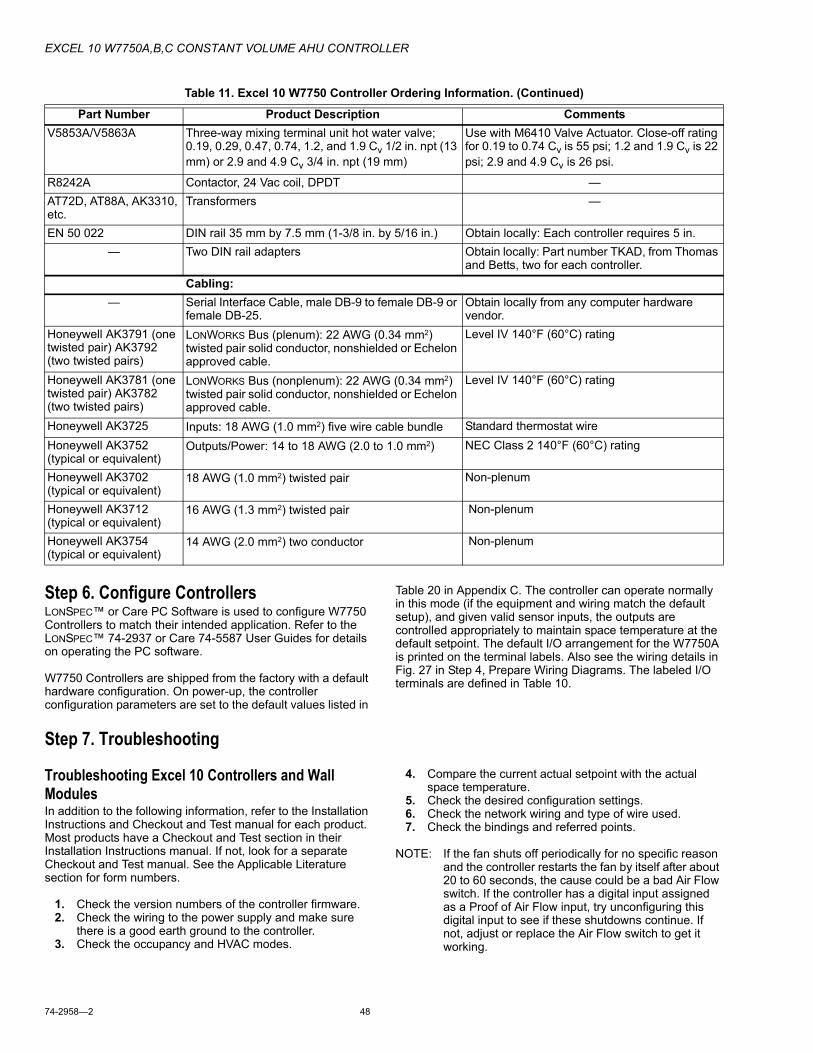
EXCEL 10 W7750A,B,C CONSTANT VOLUME AHU CONTROLLER
74-2958�2 48
Step 6. Configure ControllersLONSPEC� or Care PC Software is used to configure W7750 Controllers to match their intended application. Refer to the LONSPEC� 74-2937 or Care 74-5587 User Guides for details on operating the PC software.
W7750 Controllers are shipped from the factory with a default hardware configuration. On power-up, the controller configuration parameters are set to the default values listed in
Table 20 in Appendix C. The controller can operate normally in this mode (if the equipment and wiring match the default setup), and given valid sensor inputs, the outputs are controlled appropriately to maintain space temperature at the default setpoint. The default I/O arrangement for the W7750A is printed on the terminal labels. Also see the wiring details in Fig. 27 in Step 4, Prepare Wiring Diagrams. The labeled I/O terminals are defined in Table 10.
Step 7. Troubleshooting
Troubleshooting Excel 10 Controllers and Wall ModulesIn addition to the following information, refer to the Installation Instructions and Checkout and Test manual for each product. Most products have a Checkout and Test section in their Installation Instructions manual. If not, look for a separate Checkout and Test manual. See the Applicable Literature section for form numbers.
1. Check the version numbers of the controller firmware.2. Check the wiring to the power supply and make sure
there is a good earth ground to the controller.3. Check the occupancy and HVAC modes.
4. Compare the current actual setpoint with the actual space temperature.
5. Check the desired configuration settings.6. Check the network wiring and type of wire used.7. Check the bindings and referred points.
NOTE: If the fan shuts off periodically for no specific reason and the controller restarts the fan by itself after about 20 to 60 seconds, the cause could be a bad Air Flow switch. If the controller has a digital input assigned as a Proof of Air Flow input, try unconfiguring this digital input to see if these shutdowns continue. If not, adjust or replace the Air Flow switch to get it working.
V5853A/V5863A Three-way mixing terminal unit hot water valve; 0.19, 0.29, 0.47, 0.74, 1.2, and 1.9 Cv 1/2 in. npt (13 mm) or 2.9 and 4.9 Cv 3/4 in. npt (19 mm)
Use with M6410 Valve Actuator. Close-off rating for 0.19 to 0.74 Cv is 55 psi; 1.2 and 1.9 Cv is 22 psi; 2.9 and 4.9 Cv is 26 psi.
R8242A Contactor, 24 Vac coil, DPDT �AT72D, AT88A, AK3310, etc.
Transformers �
EN 50 022 DIN rail 35 mm by 7.5 mm (1-3/8 in. by 5/16 in.) Obtain locally: Each controller requires 5 in.� Two DIN rail adapters Obtain locally: Part number TKAD, from Thomas
and Betts, two for each controller.Cabling:
� Serial Interface Cable, male DB-9 to female DB-9 or female DB-25.
Obtain locally from any computer hardware vendor.
Honeywell AK3791 (one twisted pair) AK3792 (two twisted pairs)
LONWORKS Bus (plenum): 22 AWG (0.34 mm2) twisted pair solid conductor, nonshielded or Echelon approved cable.
Level IV 140°F (60°C) rating
Honeywell AK3781 (one twisted pair) AK3782 (two twisted pairs)
LONWORKS Bus (nonplenum): 22 AWG (0.34 mm2) twisted pair solid conductor, nonshielded or Echelon approved cable.
Level IV 140°F (60°C) rating
Honeywell AK3725 Inputs: 18 AWG (1.0 mm2) five wire cable bundle Standard thermostat wireHoneywell AK3752 (typical or equivalent)
Outputs/Power: 14 to 18 AWG (2.0 to 1.0 mm2) NEC Class 2 140°F (60°C) rating
Honeywell AK3702 (typical or equivalent)
18 AWG (1.0 mm2) twisted pair Non-plenum
Honeywell AK3712 (typical or equivalent)
16 AWG (1.3 mm2) twisted pair Non-plenum
Honeywell AK3754 (typical or equivalent)
14 AWG (2.0 mm2) two conductor Non-plenum
Table 11. Excel 10 W7750 Controller Ordering Information. (Continued) Part Number Product Description Comments

EXCEL 10 W7750A,B,C CONSTANT VOLUME AHU CONTROLLER
49 74-2958�2
Temperature Sensor and Setpoint Potentiometer Resistance RangesThe T7770 or T7560A,B Wall Modules or the C7770A Air Temperature Sensor has the following specified calibration points, which are plotted in Fig. 40:
Temperature (°F) Resistance Value (ohms)98 1175580 1847870 2402860 3152542 52675
The T7770 Wall Module setpoint potentiometers have the following linear calibration points:
Temperature (°F) Resistance Value (ohms)85 142670 550055 9574
Fig. 40. Temperature sensor resistance plots.
NOTE: 10K ohm values apply to the T7770A3xxx Sensors.
AlarmsWhen an Excel 10 has an alarm condition, it reports it to the central node on the LONWORKS Bus (typically, the Excel 15A Building Manager or the Excel 10 Zone Manager). See Table 12. Information contained in an alarm message is:
� Subnet Number:LONWORKS Bus subnet that contains the Excel 10 node that has the alarm condition.
� Node Number:Excel 10 node that has the alarm condition (see Network Alarm).
� Alarm Type:Specific alarm being issued. An Excel 10 can provide the alarm types listed in Table 12.
TEMPERATURE (DEGREES)
oF30 40 50 60 70 80 90 100 110
0 10 20 30 40
RE
SIS
TA
NC
E (
OH
MS
)
20K OHM AT 77oF (25oC)
80K
70K
60K
50K
40K
30K
20K
10K
oC
M11620
AIR TEMPERATURE SENSOR
10K OHM SETPOINT POTRESISTANCE VALUES

EXCEL 10 W7750A,B,C CONSTANT VOLUME AHU CONTROLLER
74-2958�2 50
NOTE: The node can be reset by switching the node to MANUAL and then to the normal operating mode (see Fan Operation in Appendix B).
Also, the Excel 10 variables, AlarmLogX where X is 1 through 5, that store the last five alarms to occur in the controller, are available. These points can be viewed through LONSPEC� LONSTATION� or Care.
Certain alarm conditions are suppressed conditionally as follows:
Broadcasting the Service MessageThe Service Message allows a device on the LONWORKS Bus to be positively identified. The Service Message contains the controller ID number and, therefore, can be used to confirm the physical location of a particular Excel 10 in a building.
There are three methods of broadcasting the Service Message from an Excel 10 W7750 Controller. One uses a hardware service pin button on the side of the controller (see Fig. 41). The second uses the wall module pushbutton (see
Fig. 43 and 44). By pressing the wall module pushbutton for more than four seconds, the controller sends out the Service Message. The third involves using the PC Configuration tool, as follows.
When an Assign ID command is issued from the commissioning tool, the node goes into the SERVICE_MESSAGE mode for five minutes. In the SERVICE_MESSAGE mode, pressing the Occupancy Override button on the remote wall module (refer to Fig. 43 and 44 for override button location) causes the Service Message to be broadcast on the network. All other functions are normal in the SERVICE_MESSAGE mode. Even if an Excel 10 W7750 Controller does not have an Override button connected, it can broadcast the Service Message on the network by temporarily shorting the Controller Bypass Input terminal to the Sensor Ground terminal on the W7750A,B,C (short terminals 3 and 5).
The LONSPEC� or Care PC tool is used to perform the ID Assignment task.
Table 12. Excel 10 Alarms.
Name of alarm or error bitAlarm type
number Meaning of alarm code or error bitRETURN_TO_NORMAL 128U Return to no alarm after being in an alarm condition. This code is added
numerically to another alarm code to indicate that the alarm condition has returned to normal.
ALARM_NOTIFY_DISABLED 255U The alarm reporting was turned off by DestManMode. No more alarms are reported until DestManMode turns on alarm reporting or on application restart.
NO_ALARM 0 No alarms presently detected.INPUT_NV_FAILURE 1 One or more NV inputs have failed in receiving an update within their specified
FAILURE_DETECT_TIME.NODE_DISABLED 2 The control algorithm has stopped because the controller is in
DISABLED_MODE, MANUAL or FACTORY_TEST mode. No more alarms are reported when the controller is in the DISABLED_MODE. Alarms continue to be reported if the controller is in the MANUAL or FACTORY_TEST mode.
SENSOR_FAILURE 3 One or more sensors have failed.FROST_PROTECTION_ALARM 4 The space temperature is below the frost alarm limit 42.8°F (6°C) when the
mode is FREEZE_PROTECT. The alarm condition remains until the temperature exceeds the alarm limit plus hysterisis.
INVALID_SET_POINT 5 One of the setpoints is not in the valid range.LOSS_OF_AIR_FLOW 6 The Fan Status DI indicates that there is no air flow when the node is
commanding the fan to run. The control is shut down and disabled until power is cycled or the node is reset. See NOTE below. The alarm is not issued until FanFailTime seconds have elapsed since the loss-of-flow condition was first reported
DIRTY_FILTER 7 The pressure drop across the filter exceeds the limit and the filter requires maintenance. The control runs normally.
SMOKE_ALARM 8 The smoke detector has detected smoke and the node has entered an emergency state.
IAQ_OVERRIDE 9 The indoor air quality sensor has detected that the indoor air quality is less than the desired standard and additional outdoor air is being brought into the conditioned space.
LOW_LIM_ECON_CLOSE 10 The economizer has to close beyond the minimum position to prevent the discharge air temperature from going below the discharge temperature low limit.

EXCEL 10 W7750A,B,C CONSTANT VOLUME AHU CONTROLLER
51 74-2958�2
Fig. 41. Location of the Service Pin Button.
W7750 Controller Status LEDThe LED on the front and center of a W7750 Controller provides a visual indication of the status of the device. See Fig. 42. When the W7750 receives power, the LED should appear in one of the following allowable states:
1. Off�no power to the processor.2. Continuously On�processor is in initialized state.3. Slow Blink�controlling, normal state.4. Fast Blink�when the Excel 10 has an alarm condition.
Fig. 42. LED location on W7750.
T7770C,D Wall Module Bypass Pushbutton and Override LEDPressing the bypass pushbutton, located on the T7770C,D Wall Modules in Fig. 43, causes the override LED to display the Manual Override mode of the controller. The modes are:
Fig. 43. The T7770C,D Wall Modules LED and Bypass pushbutton locations.
1. LED = Off. No override active.2. LED = Continuously on. Bypass mode (timed Occupied
override).3. LED = One flash per second. Continuous Unoccupied
override.4. LED = Two flashes per second. Remote only, continu-
ous Occupied override.
T7560A,B Bypass Pushbutton and LCD Display Occupancy SymbolsSee Fig. 44 for the T7560A,B Digital Wall Module bypass pushbutton location.
Press and release the bypass pushbutton, located on the T7560A,B Digital Wall Modules in Fig. 44 for more than one second to cause the sun symbol on the bottom right side of the LCD display to appear. Pressing the bypass pushbutton for more than four seconds causes the controller, hard-wired to the T7560A,B, to go into continuous unoccupied override. The T7560A,B displays the moon symbol.
Fig. 44. T7560A,B Digital Wall Module Bypass pushbutton location.
M10094
SERVICEPINBUTTON
M10095A
W7750
1 2 3 4 5 6 7 8 9 10 11 12 13 14 15 J3
31 30 29 28 27 26 25 24 23 22 21 20 19 18 17 16
E GND
LED BYPASS SNSRSET PT AI-1
OHMA1-2 OHM
AI-3 V/mA
AI-4V/mA
20VDCOUT
DI-4DI-3 DI-2
DI-1VAC
24
VAC
24COM
1
OUT2
OUT3
OUT4
OUT5
OUT6
OUT7
OUT8
OUT
AIGND AI
GND AIGND LONWORKS
-BUSLONJACK
DIGND DI
GND
STATUSLED
M11617
T7770C T7770D
OVERRIDELED
BYPASSPUSHBUTTON
BYPASSPUSHBUTTON
7065
60
55
75
80
85
OVERRIDELED
M17500
BYPASSPUSHBUTTON

EXCEL 10 W7750A,B,C CONSTANT VOLUME AHU CONTROLLER
74-2958�2 52
APPENDICES
Appendix A: Using LONSPEC�/Care to Commission a W7750 ControllerNOTE: When commissioning a CVAHU W7750 Controller,
the PC tool first checks that the actual hardware model (such as W7750A,B,C) is the same type which was selected from the Application Selection/Output tab. If the types do not match, the download does not occur and the user-entered values in the Application Selection screens all revert back to default values.
Sensor CalibrationThe space temperature, the optional resistive and voltage/current (W7750B,C only) inputs can all be calibrated. The wall module setpoint potentiometer can not be calibrated.
Perform the sensor calibration by adding an offset value (either positive or negative) to the sensed value using LONSPEC� or Care.
When calibrating voltage/current sensors on the (W7750B,C), the offset amount entered by the user is in volts, regardless of the inputs actual engineering units. See Appendix E for information on how to derive the proper voltage value to enter as an offset during calibration.
Setting the Pid ParametersThe W7750 is designed to control a wide variety of mechanical systems in many types of buildings. With this flexibility, it is necessary to verify the stability of the temperature control in each different type of application. Occasionally, the PID parameters require tuning to optimize comfort and smooth equipment operation. This applies to the W7750A,B,C Controllers.
CVAHU Controllers are configured by LONSPEC� or Care with default values of PID parameters as shown in Appendix C Table 21. If different values for these parameters are desired, Table 13 lists some recommended values to use as a starting point. These recommended values are based on past experience with the applications and in most cases do not require further adjustment.
Table 13. Recommended Values For PID Parameters.
If the PID parameters require adjustment away from these values, use caution to ensure that equipment problems do not arise (see Important below). If any change to PID control parameters is made, the adjustments should be gradual. After each change, the system should be allowed to stabilize so the effects of the change can be accurately observed. Then further refinements can made, as needed, until the system is operating as desired.
IMPORTANTMaking large or frequent changes to PID control parameters can cause equipment problems such as short cycling compressors (if stage minimum run times were disabled in User Addresses DisMinClTime or DisMinHtTime). Other problems that can occur include wide swings in space temperature and excessive overdriving of modulating outputs.
If adjustment of PID parameters is required, use the following. In the items that follow, the term, error, refers to the difference between the measured space temperature and the current actual space temperature setpoint.
� The Proportional Gain (also called Throttling Range) determines how much impact the error has on the output signal. Decreasing the Proportional Gain amplifies the effect of the error; that is, for a given error, a small Proportional Gain causes a higher output signal value.
� The Integral Gain (also called Integral Time) determines how much impact the error-over-time has on the output signal. Error-over-time has two components making up its value: the amount of time the error exists; and the size of the error. The higher the Integral Gain, the slower the control response. In other words, a decrease in Integral Gain causes a more rapid response in the output signal.
� The Derivative Gain (also called Derivative Time) determines how much impact the error rate has on the output signal. The error rate is how fast the error value is changing. It can also be the direction the space temperature is going, either toward or away from the setpoint, and its speed�quickly or slowly. A decrease in Derivative Gain causes a given error rate to have a larger effect on the output signal.
� The Control Band is used only for discharge temperature control of modulating outputs, which includes controlling the economizer dampers, and heating and cooling valves using Cascade Control. The Control Band dictates the
Equipment Configuration
Heat Prop. Gain
Heat Integ. Gain
Heat Deriv. Gain
Heat Control Band
Cool Prop. Gain
Cool Integ. Gain
Cool Deriv. Gain
Cool Control Band
Econ Control Band
Single Stage 2 3000 0 10 2 3000 0 10 10Two Stages 3 2000 0 10 3 2000 0 10 10Three Stages 4.5 1500 0 10 4.5 1500 0 10 10Four Stages 6 1000 0 10 6 1000 0 10 10Series 60 Modulating (Floating) 2 750 0 10 2 750 0 10 10PWM Modulating 2 900 0 10 2 900 0 10 10
EXCEL 10 W7750A,B,C CONSTANT VOLUME AHU CONTROLLER
53 74-2958�2
span through which the discharge temperature must travel to cause the output signal to go from fully closed to fully open. Also, 10 percent of the Control Band value is the size of the deadband around the setpoint where no actuator motion occurs. For example, if controlling a cooling valve with Cascade Control enabled and with the discharge temperature within 0.1 X DaTempClCtrlBd of the discharge setpoint, there is no change in the current valve position.The smaller the Control Band, the more responsive the
control output. A larger Control Band causes more sluggish control. Be careful not to set the Control Band too low and cause large over or under shoots (hunting). This can happen if the space or discharge sensors or wiring are in noisy environments and the value reported to the controller is not stable (such that it bounces). The Control Band is used only in modulating control, and has no purpose when staged control is configured.
Appendix B: Sequences of OperationThis Appendix provides the control sequences of operation for the models of the Excel 10 W7750 CVAHU Controller. The W7750A,B,C Controllers can be configured to control a wide variety of possible equipment arrangements. Tables 14 and 15 (copied from Tables 3 and 4) summarize the available options. This Appendix provides a more detailed discussion of these options.
Common OperationsThe Excel 10 W7750 Controller applications have many common operations that are applicable regardless of the type of heating, cooling, or economizer equipment configuration. These operations are available to the W7750A and the W7750B,C Versions of the CVAHU Controller, and the I/O and network configurations for them are summarized in Table 14.
Available input options are from the wall module and the hard-wired analog and digital inputs. Each application can have only a subset of these devices configured based on the number of physical I/O points available. However, some of the inputs are available over the LONWORKS Bus network.
NOTE: Each W7750 Controller must have a space temperature sensor input either wired directly to the controller, or shared from another LONWORKS Bus device, and must have a digital output configured for controlling the supply fan. In addition, if modulating economizer control is desired, a discharge air temperature sensor must be physically connected to the Excel 10 W7750 Controller. A discharge temperature signal cannot be brought into the controller through the LONWORKS Bus network.
Table 14. Common Configuration Options Summary For W7750A,B,C Controllers.Option Possible Configurations Common To All W7750 Models
Supply Fan 1. Mandatory Digital Output.Type of Air Handler 1. Conventional.
2. Heat Pump.Occupancy Sensor 1. None.
2. Connected: Contacts closed equals Occupied.3. Network (Occ/Unocc signal received via the LONWORKS Bus network).
Window Sensor 1. None.2. Physically Connected: Contacts closed equals window closed.3. Network (Window Open/Closed signal received via the LONWORKS Bus).
Wall Module Option(The T7560A,B have an optional accessory for LONWORKS Bus access)
1. Local (direct wired to the controller).2. Network (sensor value received via the LONWORKS Bus).
Wall Module TypeAll wall modules have a LONWORKS Bus access jack. (The T7560A,B requires an optional accessory.)
1. Sensor only.2. Sensor and Setpoint adjust.3. Sensor, Setpoint adjust and Bypass.4. Sensor and Bypass.
Smoke Emergency Initiation 1. None.2. Physically Connected: Contacts closed equals smoke detected.3. Network (Emergency/Normal signal received via the LONWORKS Bus).

EXCEL 10 W7750A,B,C CONSTANT VOLUME AHU CONTROLLER
74-2958�2 54
Table 15. Configuration Options Summary For W7750A,B,C Controllers.
ROOM TEMPERATURE SENSOR (RmTemp)This is the room space temperature sensor. This sensor is the T7770 or the T7560A,B Wall Module. When it is configured, it provides the temperature input for the W7750 temperature control loop. If it is not configured, it is required that a room temperature sensor value be transmitted from another
LONWORKS Bus device. If no valid room temperature value is available to the W7750 Controller, the temperature control algorithm in the controller is disabled, causing the heating, cooling, and economizer control outputs to be turned off. If the W7750 Controller is configured for Continuous Fan (rather
OptionPossible Configurations for the
W7750A Model Possible Configurations for the W7750B,C ModelsType of 1. One stage. 1. One stage.Heating 2. Two stages. 2. Two stages.
3. Three stages. 3. Three stages.4. Four stages. 4. Four stages.5. None. 5. Series 60 Modulating electric valve, or pneumatic via transducer.
6. Pulse Width Modulating electric valve, or pneumatic via transducer.7. None.
Type of 1. One stage. 1. One stage.Cooling 2. Two stages. 2. Two stages.
3. Three stages. 3. Three stages.4. Four stages. 4. Four stages.5. None. 5. Series 60 Modulating electric valve, or pneumatic via transducer.
6. Pulse Width Modulating electric valve, or pneumatic via transducer.7. None.
Type of Economizer
1. Digital Output Enable/Disable signal for controlling an external economizer package.
1. Digital Output Enable/Disable signal for controlling an external economizer package.
2. Series 60 Modulating electric damper motor, or pneumatic via transducer.
2. Series 60 Modulating electric damper motor, or pneumatic via transducer.
3. None. 3. Pulse Width Modulating electric damper motor, or pneumatic via transducer.
4. None.IAQ Option 1. None. 1. None.
2. Local IAQ Digital Input�directly wired to the controller. (Contacts closed means poor IAQ is detected.)
2. Local IAQ Digital Input�directly wired to the controller. (Contacts closed means poor IAQ is detected.)
3. Network (IAQ Override signal received via the LONWORKS Bus).
3. Network (IAQ Override signal received via the LONWORKS Bus).
4. Local CO2 Analog Input�directly wired to the controller. (The sensor must be a 0 to 10V device representing 0 to 2000 PPM CO2.)
Coil Freeze 1. None. 1. None.Stat Option 2. Local Coil Freeze Stat Digital
Input�directly wired to the controller. (Contacts closed means that coil freeze condition is sensed.)
2. Local Coil Freeze Stat Digital Input�directly wired to the controller. (Contacts closed means that coil freeze condition is sensed.)
Filter Monitor 1. None. 1. None.Option 2. Local Dirty Filter Digital
Input�directly wired to the controller. (Contacts closed means that the filter is dirty.)
2. Local Dirty Filter Digital Input�directly wired to the controller. (Contacts closed means that the filter is dirty.)
3. Local Analog Input for Differential Pressure across the Filter (directly wired to the controller). The sensor must be a 2 to 10V device representing 0 to 5 in. w.c. (1.25 kPa).

EXCEL 10 W7750A,B,C CONSTANT VOLUME AHU CONTROLLER
55 74-2958�2
than Intermittent Fan (see Fan Operation in this Appendix), and the mode is Occupied when the RmTemp value becomes invalid, the fan continues to run.
REMOTE SETPOINT (RmtStptPot)
NOTE: Unocc heat and cool setpoints cannot be changed without the pc tool.
This is the Setpoint Potentiometer contained in the T7770 or the T7560A,B Wall Module. When configured, this occupant value is set to calculate the actual cooling or heating Occupied Setpoint. There are two options for how to calculate the actual setpoint to be used by the temperature control algorithm: (Offset) and (Absolute Middle). When SetPtKnob is set to Offset, the Wall Module setpoint knob represents a number from -9° to +9°F (-5° to +5°C) which is added to the software occupied setpoints for the heat and the cool modes (CoolOccSpt and HeatOccSpt). When SetPtKnob is set to Absolute Middle, the setpoint knob becomes the center of the Zero Energy Band (ZEB) between the cooling and heating occupied setpoints. The size of the ZEB is found by taking the difference between the software heating and cooling occupied setpoints; therefore, for Absolute Middle, the actual setpoints are found as follows:
ActualCoolSpt = RmtStptPot + (CoolOccSpt - HeatOccSpt) / 2
ActualHeatSpt = RmtStptPot - (CoolOccSpt - HeatOccSpt) / 2
During Standby and Unoccupied times, the remote setpoint pot is not referenced, and the software setpoints for those modes are used instead.
SETPOINT LIMITS (LoSetptLim AND HiSetptLim)Remote setpoint pot limits are provided by LoSetptLim and HiSetptLim. The occupied setpoints used in the control algorithms are limited by these parameters. When the setpoint knob is configured to be of type Absolute Middle, the lowest actual setpoint allowed is equal to LoSetptLim, and the highest actual setpoint allowed is equal to HiSetptLim. When the setpoint knob is configured to be an Offset type, the lowest actual setpoint allowed is equal to HeatOccSpt - LoSetptLim, and the highest allowed is equal to CoolOccSpt + HiSetptLim.
BYPASS MODE (StatusOvrd AND StatusLed)During Unoccupied periods, the facility occupant can request that Occupied temperature control setpoints be observed by depressing the Bypass pushbutton on the wall module. When activated, the controller remains in Bypass mode until:
1. Bypass Duration Setting has timed out (BypTime), or2. User again presses the Wall Module pushbutton to
switch off Bypass mode, or3. Occupancy schedule (DestSchedOcc network input or
TimeClckOcc digital input) switches the mode to Occupied.
4. User sets the DestManOcc network point to Not Assigned.
The LED on the T7770 Wall Module (Override LED) indicates the current bypass mode status (see the T7770C,D Wall Module Bypass Pushbutton and Override LED section). The LCD on the T7560 Digital Wall Module indicates the current bypass mode status (see the T7560A,B Digital Wall Module Bypass Pushbutton and LCD Occupancy Symbols section).
BypassTimeBypassTime is the time between the pressing of the override button at the wall module (or initiating OC_BYPASS via nviManOcc) and the return to the original occupancy state. When the bypass state has been activated, the bypass timer is set to BypassTime (default of 180 minutes).
OverrideTypeOverrideType specifies the behavior of the override button on the wall module. There are three possible states that have the following meanings:
NONE disables the override button.NORMAL causes the override button to set the OverRide
state to OC_BYPASS for BypassTime (default 180 minutes), when the override button has been pressed for approximately 1 to 4 seconds, or to set the OverRide state to UNOCC when the button has been pressed for approximately 4 to 7 seconds. When the button is pressed longer than approximately 7 seconds, then the OverRide state is set to OC_NUL (no manual override is active).
BYPASS_ONLY causes the override button to set the OverRide state to OC_BYPASS for BypassTime (default 180 minutes), on the first press (1 to 7 seconds). On the next press, the OverRide state is set to OC_NUL (no manual over ride is active).
OverridePriorityOverridePriority configures the override arbitration between nviManOcc, nviBypass.state, and the wall module override button. There are two possible states which have the following meanings:
LAST specifies that the last command received from either the wall module or nviManOcc determines the effective override state.
NET specifies that when nviManOcc is not OC_NUL, then the effective occupancy is nviManOcc regardless of the wall module override state.
CYCLES PER HOUR (ubHeatCph AND ubCoolCph)ubHeatCph specifies the mid-load number of on / off cycles per hour (default is 6), when the mode is HEAT. ubCoolCph specifies the mid-load number of on / off cycles per hour (default is 3), when the mode is COOL. This is to protect the mechanical equipment against short cycling causing excessive wear. In addition the cycle rate specifies the minimum on and off time according to Table 17.
T7770C,D OR T7560A,B WALL MODULE BYPASS PUSHBUTTON OPERATIONThe Wall Module Bypass pushbutton is located on both the T7770C,D or the T7560A,B Wall Modules, see Fig. 43 and 44. The bypass pushbutton can change the controller into various occupancy modes, see Table 16.
Table 16. Bypass Pushbutton Operation.
If the pushbutton is held down for
But for not more than The resulting mode is
Less than 1 second � No Override is active1 second 4 seconds Bypass (a timed Occupied
Override)4 seconds 7 seconds Continuous Unoccupied
Override

EXCEL 10 W7750A,B,C CONSTANT VOLUME AHU CONTROLLER
74-2958�2 56
NOTES: If the pushbutton is held down for longer than seven seconds, the controller reverts back to No Override and repeats the cycle above. See Fig. 45.
Continuous Occupied override mode can only be initiated remotely; that is, over the LONWORKS Bus network.
Fig. 45. LED and Bypass pushbutton operation.
STANDBY MODE (StatusOcySen)The digital input for an occupancy sensor (usually a motion detector or possibly a time clock) provides the controller with a means to enter an energy-saving Standby mode whenever people are not in the room. Standby mode occurs when the scheduled occupancy is Occupied, and the occupancy sensor detects no people currently in the room (digital input contacts Closed means people are in the room, and contacts Open means the room is Unoccupied). When in Standby mode, the Excel 10 W7750 Controller uses the Standby Cooling Setpoint for cooling (CoolStbySpt), or the Standby Heating Setpoint for Heating (HeatStbySpt) as the Actual Space Temperature Setpoint. The occupancy sensor signal can also be a network input from another LONWORKS Bus device, so that no physical sensor is required at the receiving W7750 Controller.
IMPORTANTWhen the W7750 Controller is in Standby mode, the economizer minimum position setting is not observed. This means the fresh air dampers will go fully closed if there is no call for cooling.
CONTINUOUS UNOCCUPIED MODEThis mode is entered when a wall module is configured with a Bypass pushbutton that was pressed for four to seven seconds causing the wall module LED/LCD to blink. This mode can also be entered via a network command (ManualOcc set to Unoccupied). If the controller is in this mode, it reverts to the Unoccupied setpoints for temperature control, and the economizer does not observe its minimum position setting. The controller remains in this mode indefinitely until the Bypass pushbutton is pressed to exit the mode or a network command is sent to clear the mode. A configuration parameter is available to disable wall-module initiation of Continuous Unoccupied mode (OvrdType).
OCCUPANCY MODE AND MANUAL OVERRIDE ARBITRATIONThe W7750 has multiple sources for occupancy schedule information and, therefore, it employs an arbitration scheme to determine the current actual mode. Time-of-day (TOD) schedule status comes from two sources, a configured digital input for OccTimeClock or the DestSchedOcc network input received from a central control. If the digital input source is configured, it has highest priority and determines the Occupancy mode. This digital input is either ON (shorted = occupied), OFF (open = unoccupied), or not active (not configured); otherwise, the status is determined by the DestSchedOcc input from the network source. The DestSchedOcc has three possible states, occupied, unoccupied or standby.
Manual Override Status can be derived from three sources and governed by two selectable arbitration schemes. The two schemes are:� Network Wins or Last-in Wins, as set in OvrdPriority.
The three sources of manual override status are:DestManOcc - Has possible states: Occupied,
Unoccupied, Bypass, Standby and Not Assigned (not active). This input source has the highest priority in determining manual override status for a Network Wins arbitration scheme, and in the event there is more than one source change at a time in the Last-in Wins arbitration scheme. Here, bypass initiates a self-timed bypass of the control unit and expires upon completion of the defined timed period. The controller then treats the bypass status of this input as Not Assigned until the next change in status.
M8483A
RESET
NOT ASSIGNED(LED OFF)
PRESS FOR ONETO FOUR SECONDS
BYPASS OCCUPIED(LED ON)
BYPASSTIMEOUT
PRESS FOR FOUR TO SEVEN SECONDS
PRESS FOR LESS THAN ONE SECOND
UNOCCUPIED(LED BLINK)
PRESS FOR LESS THAN ONE SECOND
PRESS FOR MORE THAN SEVEN SECONDS

EXCEL 10 W7750A,B,C CONSTANT VOLUME AHU CONTROLLER
57 74-2958�2
DestBypass - Has possible states: Bypass On, Bypass Off or Not Assigned (not active). This input places the controller in an untimed bypass state or turns off the bypass mode. This source is second in priority to DestManOcc under the same arbitration schemes mentioned above.
Override Button -The wall module Override pushbutton can command status of Bypass, Continuous Unoccupied and Not Assigned. This source has the lowest priority status in the above mentioned schemes. The above mention sources of override must be either Not Assigned or Off before the Override pushbutton affects the manual override status in the Network Wins scheme. All actions, in this case, taken from the Override pushbutton are locked out.
Bypass status is a controller-timed event whose duration is set in BypTime. Upon expiration of the timer, the status returns to Not Assigned. The status of this input can be overridden with the receipt of Not Assigned from DestManOcc. This, in effect, cancels a timed bypass or a continuous unoccupied mode.
The Override pushbutton can be configured as Normal (all of the above mentioned states are possible), Bypass Only (Bypass and Not Assigned only) or None (effectively Disabling the Override pushbutton).
TIME CLOCK (Occ_Time_Clock)OccTimeClock is the state of the digital input configured and wired to a time clock. When the digital input is detected to be Closed (Occupied), the scheduled occupancy will be OC_OCCUPIED. If the detected state of the digital input is Open (Unoccupied), then the scheduled occupancy will be OC_UNOCCUPIED. If the Occ_Time_Clock is not configured, then either the DestSchedOcc network input received from a central control or the time clock that is broadcast from a Sched_Master configured W7750, controls the occupied mode.
SCHEDULE MASTER (Sched_Master)Sched_Master is the state of a digital input that is configured and wired to the W7750. If the Sched_Master input is closed (input shorted), the node is the schedule master and the state of the locally connected time clock will be broadcast out over the LONWORKS Bus to the other W7750 controllers. If the Sched_Master input is open, then the node is not a schedule master and the local time clock will not be sent out over the LONWORKS Bus even if the time clock input is configured. However, the DestSchedOcc network input received from a central control has a higher priority than the local time clock, and therefore overrides the local time clock. The W7750 controllers automatically bind without the need for a configuration tool.
SETPOINT RAMPINGThe W7750 Controller incorporates a ramping feature that gradually changes the space setpoints between occupancy modes. This feature is only operational if the network variable inputs DestSchedOcc, TodEventNext, and Time Until Next Change Of State (TUNCOS) are being used to change the W7750 Occupancy mode. The applicable Setpoints are OaTempMinHtRamp, OaTempMaxHtRamp, MinHtRamp and MaxHtRamp (for HEAT mode operation), and OaTempMinClRamp, OaTempMaxClRamp, MinClRamp and MaxClRamp (for the COOL mode operation). See Fig. 46 for a pictorial representation of how these setpoints interact.
During recovery operation, the setpoint changes at a rate in degrees per hour depending on the outdoor air temperature. If there is no outdoor air temperature sensor available, then MinHtRamp is used as the recovery rate.
Fig. 46. Setpoint ramping parameters with ramp rate calculation.
NOTE: Recovery ramping applies between scheduled heating or cooling setpoint changes from UNOCCUPIED to STANDBY, UNOCCUPIED to OCCUPIED, and STANDBY to OCCUPIED. Scheduled setpoint changes from OCCUPIED to UNOCCUPIED or OCCUPIED to STANDBY do not use a ramped setpoint but instead use a step change in setpoint. Recovery ramps begin before the next scheduled occupancy time and are ramped from the setpoint for the existing scheduled occupancy state to the setpoint for the next occupancy state.
RECOVERY RAMPING FOR HEAT PUMP SYSTEMSWhen the node is controlling heat pump equipment, during the recovery ramps, the heating setpoint is split into a heat pump setpoint (for compressors) and an auxiliary heat setpoint (for auxiliary heat stages). The heat pump setpoint is a step change at the recovery time prior to the OCCUPIED time. Recovery time is computed from the configured heat recovery ramp rate. The recovery time is calculated:Recovery time = (OCC setpoint - current setpoint)/ramp rate
See Fig. 47 for the various setpoints.
HEAT RECOVERY RAMP RATE(DEGREES/HOUR)
MaxHtRamp
MinHtRamp
OaTempMinHtRamp OaTempMaxHtRamp
OUTDOOR AIRTEMPERATURE
M10109A

EXCEL 10 W7750A,B,C CONSTANT VOLUME AHU CONTROLLER
74-2958�2 58
Fig. 47. Setpoint ramping parameters with setpoint calculation.
During the COOL recovery period, the setpoint changes at a rate in degrees per hour relative to the outdoor air temperature. If there is no outdoor air temperature sensor available, the MinClRamp is used as the recovery rate.
See Fig. 48 for the various setpoints.
Fig. 48. Setpoint ramping parameters with ramp rate calculation.
NOTES: The setpoint used during the COOL recovery period is similar to the heat mode in Fig. 46, except the slope of the line reverses for cooling.
Recovery ramping applies between scheduled heat-ing or cooling setpoint changes from UNOCCUPIED to STANDBY, UNOCCUPIED to OCCUPIED, and STANDBY to OCCUPIED. Scheduled setpoint changes from OCCUPIED to UNOCCUPIED or OCCUPIED to STANDBY do not use a ramped set-point, but instead, use a step change in setpoint. Recovery ramps begin before the next scheduled occupancy time and are ramped from the setpoint for the existing scheduled occupancy state to the set-point for the next occupancy state.
FAN OPERATIONThe W7750 supply fan can be controlled in one of two different ways. In Continuous Fan mode, the fan runs whenever the controller is in Occupied mode. When in Standby or Unoccupied modes, the fan cycles on with a call for cooling (or heating if the FanOnHtMode parameter is set). In Intermittent Fan mode, the fan cycles on with a call for cooling (or heating if the FanOnHtMode parameter is set), and cycles off when the space temperature control is satisfied.
The fan control supports an optional (Proof of Air Flow) digital input, that allows monitoring of the supply fans status. If the fan is commanded on, the Proof of Air Flow digital input is checked up to three times to verify that the fan is running after an initial delay of FanOnDelay seconds (adjustable). If the fan fails to start the CVAHU must be reset by first cycling CVAHU power. If this does not work, set DestManMode to Manual and then back to Enable. After a reset the application restarts�all outputs switch off and auto control is enabled.
Also, the W7750 Controller provides fan-run-on operation that keeps the fan running for a short time after heating or cooling shuts off. The amount of time that the fan continues to run is set in FanRunOnHeat for heating mode and FanRunOnCool for cooling mode.
WINDOW SENSOR (StatusWndw)The digital input for a window contact provides the algorithm with a means to disable its temperature control activities if someone has opened a window or door in the room. When a window is detected to be Open (digital input contacts Open equals window open), the normal temperature control is disabled, and the W7750 Controller enters the Freeze Protect mode. Freeze Protect mode sets the space setpoint to 46.4 °F (8°C) and brings on the fan and heat if the space temperature falls below this setpoint. Normal temperature control resumes on window closure. The Window sensor signal can also be a network input from another LONWORKS Bus device, so that no physical sensor is required at the receiving W7750 Controller.
SMOKE CONTROLThe Excel 10 W7750 Controller supports three smoke-related control strategies:
1. Emergency Shutdown (all outputs off).2. Depressurize (fan on, outdoor air damper closed).3. Pressurize (fan on, outdoor air damper open).
The controller is placed in one of these three control states whenever the W7750 mode becomes SMOKE_EMERGENCY, which can be initiated via a network command (DestEmergCmd) or from a local (physically connected) smoke detector digital input. When in SMOKE_EMERGENCY mode, the W7750 Controller uses the control strategy found in SmkCtlMode (one of the three listed above), and the normal temperature control function is disabled. If a W7750 local smoke detector trips, the SrcEmerg network variable (for other LONWORKS Bus devices to receive) is set to the Emergency state.
DEMAND LIMIT CONTROL (DLC)When The LONWORKS Bus network receives a high-electrical-demand signal, the controller applies a DlcBumpTemp amount to the current actual space temperature setpoint value. The setpoint is always adjusted in the energy-saving direction. This means that if the W7750 Controller is in Cooling mode, the DLC offset bumps the control point up, and when in Heating mode, bumps the control point down.
OCC setpoint
UN_OCC setpointOR
STANDBY setpoint
M10110
AUX HEATSETPOINT
HEAT PUMPSETPOINT(FOR COMPRESSORS)
RECOVERY TIME
OCCUPIED TIME
COOL RECOVERY RAMP RATE(DEGREES/HOUR)
MaxClRamp
MinClRamp
OaTempMinClRamp OaTempMaxClRamp
OUTDOOR AIRTEMPERATURE
M10111A

EXCEL 10 W7750A,B,C CONSTANT VOLUME AHU CONTROLLER
59 74-2958�2
DIRTY FILTER MONITORThe air filter in the air handler can be monitored by the W7750 and an alarm issued when the filter media needs replacement. The two methods of monitoring the filter are:
1. A differential pressure switch whose contacts are con-nected to a digital input on the W7750A or W7750B,C; and
2. A 2 to 10V differential pressure sensor wired to a current input on the W7750B,C. If the analog input sensor is used, its measured value 0 to 5 in. w.c. (0 to 1.25 kPa) is compared to a user-selectable setpoint (FltrPressStPt�valid range: 0 to 5 in. w.c. (0 to 1.25 kPa)), and the Dirty Filter alarm is issued when the pressure drop across the filter exceeds the setpoint.
START-UPSTART_UP_WAIT is the first mode after application restart or power-up. During START_UP_WAIT, the analog and digital inputs are being read for the first time, no control algorithms are active, and the physical outputs (fan and heat/cooling stages) are in the de-energized position. The node remains in
the START_UP_WAIT mode for a pseudo-random period (depending on neuron_id) between 12 and 22 seconds and then transitions to one of the operating modes, depending on the inputs that are read from the physical and network inputs. The pseudo random period prevents multiple controllers from simultaneously starting major electrical loads when power is restored to a building.
NOTES: After a controller download via LONSPEC�/Care, the delayed reset time is bypassed and the controller starts after a 40-second initialization.
Not all network inputs can be received during the START_UP_WAIT period because many network variables are updated at a slower rate; therefore some control decisions can be considered tempo-rarily inappropriate.
Temperature Control OperationsSee Fig. 49 for a diagram of a typical W7750 Unit.
Fig. 49. Schematic diagram for a typical W7750B Unit.
STAGED COOLING CONTROLThe Excel 10 W7750 Controller supports up to four stages of D/X cooling. As space temperature rises above the current
Cooling Setpoint, the controllers mode of operation is switched to the COOL mode. When in the COOL mode, all heating outputs are driven closed or off (with the exception
WINDOW CONTACT
OCCUPANCYSENSOR
M
OA TEMP
FILTER
FAN
COOLCOIL
HEATCOIL
DA TEMPRA TEMP
EXCEL 10W7750CVAHU
T7770 OR T7560A,BRETURNAIR
DISCHARGEAIR
OUTDOORAIR
CEILING
ROOF
- +
M17488

EXCEL 10 W7750A,B,C CONSTANT VOLUME AHU CONTROLLER
74-2958�2 60
that occurs during IAQ Override Operation, see above), and the staged cooling outputs are enabled for use. When in the COOL mode, the PID cooling control algorithm compares the current space temperature to the EffectiveCoolSetPt, and calculates a PID error signal. This error signal causes the cooling stage outputs to be cycled as required to drive the space temperature back to the setpoint. Fig. 50 illustrates the
relationship between PID error and staged output activity. As the error signal increases and the space temperature is getting farther away from setpoint, or is remaining above setpoint as time elapses, additional stages of cooling are energized until, if PID error reaches 100 percent, all configured stages are on.
Fig. 50. Staged output control versus PID Error.
If economizer dampers are configured, and the outdoor air is suitable for free cooling, the economizer operates as the first stage of cooling. For example, if a controller was configured with two stages of mechanical cooling and an economizer, the application should be viewed in Fig. 50 as a three-stage system.
Setpoints for the PID gains allow for unit-by-unit adjustment of the control loop, if required; however, any change from the default values should be minimal.
The PID control algorithm used to control staged cooling is anticipator-driven, and is similar to the algorithm used in the T7300 commercial thermostat. All staging events are subject to a minimum interstage time delay, which is based on the cycles per hour user setting (CoolCycHr). The minimum interstage time delay ranges from 90 seconds (at 12 cycles per hour) to 8.5 minutes (at two cycles per hour), see Table 17. The user has the option to disable the minimum run timer (DisMinClTimer for cooling). If the minimum run timer is disabled, the interstage time delay is fixed at 20 seconds. The cycling rate is separately selectable for heating and cooling between 2 and 12 cycles per hour (cph).
Table 17. Interstage Minimum Times
STAGED HEATING CONTROLThe Excel 10 W7750B,C Controller supports up to four stages of heating. As space temperature falls below the current Cooling Setpoint, the controller mode of operation is switched to the HEAT mode. When in the HEAT mode, all cooling outputs are driven closed or off, and the staged heating outputs are enabled for use. When in the HEAT mode, the PID cooling control algorithm compares the current space temperature to the EffectiveHeatSetPt, and calculates a PID error signal. This error signal causes the heating stage
NO. STAGES
CONFIGURED
PID
ERROR
ONE STAGE
TWO STAGES
THREE STAGES
FOUR STAGES
0% 25% 33% 50% 66% 75% 100% > 100%
CYCLING
STAGE 1
CYCLING
STAGE 1 LOCKED ON
STAGE 2 CYCLING
STAGE 1
CYCLING
STAGE 1 LOCKED ON
STAGE 2 CYCLING
STAGE 1,2 LOCKED ON
STAGE 3 CYCLING
ALL STAGES
LOCKED ON
ALL STAGES
LOCKED ON
ALL STAGES
LOCKED ON
ALL STAGES
LOCKED ON
STAGE 1
CYCLING
STAGE 1
LOCKED ON
STAGE 2
CYCLING
STAGE 1,2
LOCKED ON
STAGE 3
CYCLING
STAGE 1,2,3
LOCKED ON
STAGE 4
CYCLING
M10112
Cycles/Hour Selection Minimum On/Off time (Min.)2 8.53 5.54 4.05 3.56 3.07 2.58 2.09 2.010 2.011 1.512 1.5

EXCEL 10 W7750A,B,C CONSTANT VOLUME AHU CONTROLLER
61 74-2958�2
outputs to be cycled, as required, to drive the space temperature back to the Setpoint. Fig. 50 illustrates the relationship between PID error and staged output activity.
As the error signal increases, the space temperature gets further away from the setpoint, or is remaining below the setpoint as time elapses, additional stages of heating are energized until, if PID error reaches 100 percent, all configured stages are on.
The PID control algorithm used to control staged heating is anticipator-driven, and is similar to the algorithm used in the T7300 commercial thermostat. All staging events are subject to a minimum interstage time delay, that is based on the cycles per hour user setting (HeatCycHr). The minimum interstage time delay ranges from 90 seconds (at 12 cycles per hour) to eight minutes (at two cycles per hour). See Table 17. The user has the option to disable the minimum run timer for heating (DisMinHtTimer). If the minimum run timer is disabled, the interstage time delay is fixed at 20 seconds. The cycling rate is separately selectable for heating and cooling between two and 12 cycles per hour (cph).
Setpoints for the PID gains allow for unit-by-unit adjustment of the control loop, if required; however, any change from the default values should be minimal.
CASCADE CONTROL OF MODULATING COOLING/HEATINGThe Excel 10 W7750 Controller supports modulating cooling and heating valves. These valves can be controlled directly from the space temperature (like the staged control) or, if the CascCtrl flag is set, they are modulated to maintain the discharge air temperature at its setpoint. The discharge air setpoint is calculated based on the space temperature deviation from the space setpoint. This is commonly called cascade control. In the W7750 Controller, cascade control is available for use with PWM (W7750B,C only) and Series 60 modulating heating and cooling, but not for use with staged heating/cooling.
Setpoints for the PID gains and for the control band allow for unit-by-unit adjustment of the control loops, if required; however, any change from the default values should be minimal. Also, the W7750 Controller uses an adaptive algorithm (patent pending) to continuously assess the validity of the calculated discharge setpoint, and adjust it, as needed, to ensure precise, accurate control.
SERIES 60 MODULATING CONTROLSeries 60 Control is also commonly referred to as Floating Control. The Excel 10 W7750A,B,C Controllers can drive Series 60 type actuators (economizer only for W7750A) to control a modulating cooling valve, a heating valve, and economizer dampers. When floating control is used, the full-stroke motor drive time of the actuator must be entered into the configuration parameter CoolMtrSpd (for cooling), HeatMtrSpd (for heating), or EconMtrSpd (for the economizer dampers).
PULSE WIDTH MODULATING (PWM) CONTROLThe Excel 10 W7750B,C Controllers can drive a PWM-type actuator to control a modulating cooling valve, a heating valve, and economizer dampers. PWM control positions the actuator based on the length, in seconds, of the pulse from the digital output. The controller outputs a pulse whose length consists of two parts, a minimum and a maximum. The minimum pulse time represents the analog value of zero
percent (also indicates a signal presence) and the maximum pulse length that represents an analog value of 100 percent. If the analog value is greater than zero percent, an additional time is added to the minimum pulse time. The length of time added is directly proportional to the magnitude of the analog value. If PWM control is used, the configuration parameters for the PWM operation must be specified. These are PwmPeriod, PwmZeroScale, and PwmFullScale. These three parameters are shared by all configured PWM outputs; this means the heating, cooling, and economizer actuators must be configured to accept the same style of PWM signal.
Example: To find the pulse width of a valve actuator (for example stroke mid position - 50 percent) with the PwmZeroScale = 0.1 seconds, PwmFullScale = 25.5 seconds, and the PwmPeriod = 25.6 seconds. There are 256 increments available, so the number of increments required for 50 percent would be (0.5 X 256) or 128. The time for each increment for this industry standard pulse time is 0.1 seconds. The pulse width is the minimum time (0.1 second) + the number of increments (128 times the (0.1 second) plus 0. 1) = 12.9 seconds. The W7750B,C Controllers would command the valve output on for 12.9 seconds for the PwmPeriod of 25.6 seconds to maintain the valve position at 50 percent.
OUTDOOR AIR LOCKOUT OF HEATING/COOLINGA mechanism is provided in the W7750 to disable the heating equipment if the outdoor air temperature rises above the OaTempHtLkOut setpoint. Similarly, the cooling equipment is disabled if the outdoor air temperature falls below the OaTempClLkOut setpoint. The algorithm supplies a fixed 2°F (1.1°C) hysteresis with the lock-out control to prevent short cycling of the equipment.
ECONOMIZER DAMPER CONTROLA mixed-air economizer damper package can be controlled to assist mechanical cooling in maintaining the discharge air at setpoint. Therefore, if modulating economizer damper control is desired, a discharge air temperature sensor is required. If the outdoor air is not currently suitable for cooling use (see the Economizer Enable/Disable Control section), the outdoor air damper is held at the adjustable minimum position (EconMinPos) for ventilation purposes.
Because the outdoor air can be used to supplement mechanical cooling, the economizer operates as if it were the first stage of cooling. So, if the outdoor air is suitable for cooling use, the mechanical cooling (either staged or modulating) is held off until the economizer has reached its fully open position. Then, if the discharge temperature continues to be above setpoint, the mechanical cooling is allowed to come on. If the outdoor air is not suitable for cooling use, the economizer is set to its minimum position, and mechanical cooling is allowed to come on immediately.
When the controller is in the Heat mode, the economizer is held at the minimum position setting (EconMinPos). The minimum position setting is only used during Occupied mode operation. When in Standby or Unoccupied modes, the outdoor air dampers are allowed to fully close if there is no call for cooling, or if the outside air is not suitable for cooling use.
INDOOR AIR QUALITY (IAQ) OVERRIDEThe Excel 10 W7750 Controller supports an IAQ override feature that upon detection of poor air quality in the space, allows the economizer dampers to be opened above the standard minimum position setting to a value set in
EXCEL 10 W7750A,B,C CONSTANT VOLUME AHU CONTROLLER
74-2958�2 62
EconIAQPos. Two different methods of detecting poor air quality are supported, The first is by using an IAQ switch device connected to a digital input on the W7750 Controller, where a contact closure indicates poor air quality and initiates the IAQ override mode. The second, which is only available on the W7750B,C is through an analog input that connects to a CO2 Sensor (0 to 10V), such as the C7232A,B or C7632A,B. The measured value of CO2 from this sensor (0 to 2000 ppm) is compared to the setpoint IAQSetpt. When the CO2 level is higher than the setpoint (800 PPM), the IAQ override is initiated. The IAQSetpt hysteresis is 50 PPM, IAQ override is deactivated at a CO2 level less than 750 PPM.
When the W7750 Controller is in the COOL mode during an IAQ override, it is possible for the heating outputs to be activated. This can occur if the outdoor air temperature is cold enough to cause the discharge air temperature to drop below the DaTempLoLim setpoint when the dampers open to the EconIAQPos position, and the IaqUseHeat flag is set. If this situation occurs, the heating is controlled to maintain the discharge air temperature at 1°F (0.65°C) above the DaTempLoLim setpoint.
FREEZE STATUpon receiving a contact closure, the W7750 control algorithm will close the outdoor air damper and open the hot water and chilled water valves (if available) to the full open position as a safety precaution. If manual-reset operation is desired, the Freeze Stat device must provide the physical pushbutton, which the operator presses, to reset the system after a freeze condition has occurred.
DISCHARGE AIR LOW LIMIT CONTROLIf the discharge air temperature falls below the adjustable discharge air low limit setpoint (DaTempLoLim), an alarm is issued, and the outdoor air damper is driven below the minimum position setting until the discharge temperature is up to the low limit. If necessary, the damper can go completely closed even during Occupied mode operation. As the discharge temperature warms up, the economizer modulates open until the minimum position setting is reached. At this point, the low limit alarm is cleared.
ECONOMIZER ENABLE/DISABLE CONTROLThe W7750 Controller has inputs to determine if the outdoor air is suitable to augment cooling. The economizer dampers can be enabled/disabled for using outdoor air as the first stage of cooling based on one of ten allowable strategies:
1. Digital Input Enable/Disable�contact closure enables economizer.
2. Outdoor Temperature�when the outdoor temperature is less than OaEconEnTemp, then the outdoor air is suitable to augment cooling.
3. Outdoor Enthalpy, Type A�when the outdoor enthalpy meets the W7212 type A requirements, the outdoor air is suitable to augment cooling. See Fig. 57 and 58.
4. Outdoor Enthalpy, Type B�when the outdoor enthalpy meets the W7212 type B requirements, the outdoor air is suitable to augment cooling. See Fig. 57 and 58.
5. Outdoor Enthalpy, Type C�when the outdoor enthalpy meets the W7212 type C requirements, the outdoor air is suitable to augment cooling. See Fig. 57 and 58.
6. Outdoor Enthalpy, Type D�when the outdoor enthalpy meets the W7212 type D requirements, the outdoor air is suitable to augment cooling. See Fig. 57 and 58.
7. Differential Temperature�the difference between outdoor temperature and return air temperature is compared to DiffEconEnTemp to determine whether outdoor air or return air is more suitable for use to augment mechanical cooling.
8. Single Calculated Enthalpy�the calculated outdoor enthalpy in btu/lb is compared to the enthalpy setpoint (OaEnthEn) in btu/lb, and the outdoor temperature is compared to the outdoor temperature limit setpoint (OaEconEnTemp) for a high limit. The compared difference determines whether outdoor air is suitable for use to augment mechanical cooling.
9. Differential Enthalpy, Either Sensed or Calculated�the difference between outdoor enthalpy and return air enthalpy determines whether outdoor air or return air is more suitable to augment mechanical cooling. When enthalpy sensors are configured, they are used for comparing enthalpy. If no enthalpy sensors are available, then enthalpy is calculated using outdoor and return air humidity and temperature sensors. The switching differential is fixed at 1.0 mA for enthalpy sensors, and 0.25 btu/lb for calculated enthalpy.
NOTE: If no return temperature sensor is configured, space temperature is used to calculate return air enthalpy.
10. Network Enabled�the network input DestEconEnable controls the enabling and disabling of the economizer. When using the network input, select Econo Enable Type: No Economizer in E-Vision. The network input has priority over the other nine economizer control selections.

EXCEL 10 W7750A,B,C CONSTANT VOLUME AHU CONTROLLER
63 74-2958�2
Appendix C: Complete List of Excel 10 W7750 Controller User AddressesSee Table 18 for W7750 Controller User Address table numbers and point types.
The User Address Index following Table 18 lists the User Addresses alphabetically and gives the page number where the Address is located in each Table Number/Point Type.
An alphabetical list of Mappable User Addresses and Table Numbers follows Table 18. Following this is an alphabetical list of Failure Detect User Addresses and Table Numbers.
Table 18. Excel 10 W7750 Controller User Address Point Types.
User Address Indexes
NOTE: Following tables arranged in alphabetical order, left to right, then top to bottom.
INPUT OUTPUT POINTS (SEE TABLE 20)
CONTROL PARAMETERS (SEE TABLE 21)
ENERGY MANAGEMENT POINTS (SEE TABLE 22)
CALIBRATION POINTS (SEE TABLE 24)
Table Number Point TypesTable 20 Input/OutputTable 21 Control ParametersTable 22 Energy Management PointsTable 23 Status PointsTable 24 Calibration PointsTable 25 Configuration ParametersTable 26 LONMARK/Open System PointsTable 27 Direct Access and Special Manual PointsTable 28 Data Share Points
Address (Page) Address (Page) Address (Page)CO2Sensr (71) CORMode (67) DaTempSensr (70)EconEnSw (72) FltrPressSensr (71) IaqOvrSw (72)Model (72) ModelSw (73) MonitorSensr (71)MonitorSw (73) OaEnthSensr (71) OaHumSensr (70)OaTempSensr (70) OccSensr (72) OvrdSw (72)RaEnthSensr (70) RaHumSensr (70) RaTempSensr (70)RmTempSensr (70) RmtStptPot (70) StatusAirFlow (72)StatusDI1 (72) StatusDI2 (72) StatusDI3 (72)StatusDI4 (72) StatusDO1 (71) StatusDO2 (71)StatusDO5 (71) StatusDO3 (71) StatusDO4 (71)StatusDO6 (71) StatusDO7 (71) StatusDO8 (71)SmokeMonSw (72) TimeClkSw (72) WindowSw (73)
Address (Page) Address (Page)BypTime (77) DaTempClCtrlBd (77)DaTempEcCtrlBd (77) DaTempHiLim (74)DaTempHtCtrlBd (77) DaTempLoLim (74)DiffEconEnTemp (76) DlcBumpTemp (74)EconIAQPos (76) EconMinPos (76)FltrPressStPt (77) GainCoolDer (77)GainCoolInt (77) GainCoolProp (77)GainHeatDer (77) GainHeatInt (77)GainHeatProp (77) IAQSetpt (76)MaxClRamp (75) MinClRamp (75)MaxHtRamp (74) MinHtRamp (74)OaEconEnTemp (76) OaEnthEn (76)OaTempClLkOut (75) OaTempHtLkOut (74)OaTempMaxClRp (75) OaTempMinClRp (76)OaTempMaxHtRp (75) OaTempMinHtRp (75)PwmFullScale (76) PwmPeriod (76)PwmZeroScale (76) StptKnobHiLim (77)StptKnobLowLim (77)
Address (Page) Address (Page)DestBypass (78) DestDlcShed (78)DestFree1 (79) DestFree2 (79)DestTimeClk (80) DestWSHPEnable (79)DestSchedOcc (78) SrcBypCt (78)SrcBypass (78) SrcTimeClk (80)SrcTimeClkCt (80) TodEventNext (78)Tuncos (78)

EXCEL 10 W7750A,B,C CONSTANT VOLUME AHU CONTROLLER
74-2958�2 64
STATUS POINTS (SEE TABLE 23)
CONFIGURATION PARAMETERS (SEE TABLE 25)
LONMARK/OPEN SYSTEM POINTS (SEE TABLE 26)
DIRECT ACCESS AND SPECIAL MANUAL POINTS (SEE TABLE 27)
DATA SHARE POINTS (SEE TABLE 28)
Address (Page) Address (Page) Address (Page)AlarmLog1 (83) BypTimer (88) CO2Sens (89)CoolPos (90) CoolStgsOn (86) DaSetpt (89)DaTemp (89) DlcShed (86) EconPos (90)FilterPress (89) Free1Stat (86) Free2Stat (86)HeatPos (90) HeatStgsOn (86) MonitorSens (90)MonitorSw (87) NetConfig (93) OaEnth (89)OaEnthCalc (85) OaHum (89) OaTemp (89)OccStatOut (86) RaEnth (89) RaEnthCalc (85)RaHum (89) RaTemp (89) RmTemp (88)RmTempActSpt (88) SaFan (86) SaFanStatus (85)ShutDown (87) SrcEmerg (81) SrcTimeClk (80)StatFreezeStat (87) StatusAlmTyp (81) StatusEconEn (85)StatusEconOut (86) StatusError (90) StatusFilter (87)StatusIaqOvr (87) StatusManOcc (85) StatusMode (84)StatusOcc (84) StatusOcySen (85) StatusOvrd (84)StatusSched (84) StatusSmoke (87) StatusWndw (87)TimeClckOcc (84) WSHPEnable (88)
Address (Page) Address (Page)CascCntrl (96) CoolCycHr (94)CoolMtrSpd (95) DisMinClTime (96)DisMinHtTime (96) EconMode (94)EconMtrSpd (95) FanFailTime (95)FanMode (94) FanOnHtMode (95)FanRunOnCool (94) FanRunOnHeat (94)HeatCycHr (94) HeatMtrSpd (95)IaqUseHeat (96) OvrdPriority (97)OvrdType (97) RmTempCal (95)SetPtKnob (97) SmkCtlMode (94)TempOffstCal1 (95) TempOffstCal2 (95)UseRaTempCtl (96) UseWallModStpt (97)VoltOffstCal1 (95) VoltOffstCal2 (95)
Address (Page) Address (Page)CoolOccSpt (98) CoolUnoccSpt (98)CoolStbySpt (98) DestEconEnable (104)DestEmergCmd (101) DestHvacMode (99)DestManOcc (99) DestOaHum (100)DestOaTemp (100) DestOccSensor (103)DestRmTemp (100) DestRmTempSpt (99)DestSptOffset (99) DestWndw (104)HeatOccSpt (98) HeatStbySpt (98)HeatUnoccSpt (98) SrcEconEnable (105)SrcEconEnCt (105) SrcOaHum (100)SrcOaTemp (100) SrcOccSensor (103)SrcRmTemp (100) SrcRmTempActSpt (100)SrcUnitStatus (101) SrcWndw (104)SrcWndwCt (104)
Address (Page) Address (Page) Address (Page)DestManMode (106) TestAuxEcon (107) TestAuxHt1 (107)TestAuxHt2 (107) TestAuxHt3 (107) TestAuxHt4 (107)TestEconPos (106) TestFree1 (107) TestFree2 (107)TestHCPos (106) TestHtClMode (107) TestHtClStg1 (107)TestHtClStg2 (107) TestHtClStg3 (107) TestHtClStg4 (107)TestMode (106) TestOccStat (107) TestSaFan (107)
Address (Page) Address (Page) Address (Page)DestIaqOvrd (108) DestOaEnth (108) SrcIaqOvr (108)SrcIaqOvrCt (108) SrcMonSw (108) SrcMonSwCt (108)SrcOaEnth (108)

EXCEL 10 W7750A,B,C CONSTANT VOLUME AHU CONTROLLER
65 74-2958�2
Mappable User Addresses and Table Number
Failure Detect User Addresses and Table Number Table 19 lists the applicable Engineering Units for the analog points found in the W7750.
User Address (Table) User Address (Table) User Address (Table) User Address (Table) User Address (Table)BypTime (21) BypTimer (23) CascCntrl (25) CO2Sen (23) CoolCycHr (25)CoolMtrSpd (25) CoolOccSpt (26) CoolPos (23) CoolStbySpt (26) CoolStgsOn (23)CoolUnoccSpt (26) DaSetpt (23) DaTemp (23) DaTempClCtrlBd (21) DaTempEcCtrlBd (21)DaTempHiLim (21) DaTempHtCtrlBd (21) DaTempLoLim (21) DestDlcShed (22) DestEmergCmd (26)DestHvacMode (26) DestManMode (27) DestSchedOcc (22) DiffEconEnTemp (21) DisMinHtTime (25)DisMinClTime (25) DlcBumpTemp (21) EconIAQPos (21) EconMinPos (21) EconMtrSpd (25)EconPos (23) EconMode (25) FanFailTime (25) FanMode (25) FanOnHtMode (25)FanRunOnCool (25) FanRunOnHeat (25) FilterPress (23) FltrPressStPt (21) Free1Stat (23)Free2Stat (23) GainCoolDer (21) GainCoolInt (21) GainCoolProp (21) GainHeatDer (21)GainHeatInt (21) GainHeatProp (21) HeatCycHr (25) HeatMtrSpd (25) HeatOccSpt (26)HeatPos (23) HeatStbySpt (26) HeatStgsOn (23) HeatUnoccSpt (26) IAQSetpt (21)IaqUseHeat (25) MaxClRamp (21) MinClRamp (21) MaxHtRamp (21) MinHtRamp (21)MonitorSens (23) MonitorSw (23) OaEconEnTemp (21) OaEnth (23) OaEnthCalc (23)OaEnthEn (21) OaHum (23) OaTemp (23) OaTempClLkOut (21) OaTempHtLkOut (21)OaTempMaxClRp (21) OaTempMinClRp (21) OaTempMaxHtRp (21) OaTempMinHtRp (21) OccStatOut (23)OvrdPriority (25) OvrdType (25) PwmFullScale (21) PwmPeriod (21) PwmZeroScale (21)RaEnth (23) RaEnthCalc (23) RaHum (23) RaTemp (23) RmTempActSpt (23)RmTempCal (25) RmtStptPot (20) SaFan (23) SaFanStatus (23) SetPtKnob (25)ShutDown (23) SmkCtlMode (25) StatFreezeStat (23) StatusAlmTyp (23) StatusEconEn (23)StatusEconOut (23) StatusFilter (23) StatusIaqOvr (23) StatusManOcc (23) StatusMode (23)StatusOcc (23) StatusOcySen (23) StatusOvrd (23) StatusSched (23) StatusSmoke (23)StatusWndw (23) StptKnobHiLim (21) StptKnobLowLim (21) TimeClckOcc (23) UseRaTempCtl (25)UseWallModStpt (25) WSHPEnable (23)
User Address (Table) User Address (Table)DestBypass 22 DestDlcShed 22DestEconEnable 26 DestFree1 22DestFree2 22 DestHvacMode 26DestIaqOvrd 28 DestOaEnth 28DestOaHum 26 DestOaTemp 26DestOccSensor 26 DestRmTemp 26DestSchedOcc 22 DestSptOffset 26DestTimeClk 22 DestWndw 26DestWSHPEnable 22

EXCEL 10 W7750A,B,C CONSTANT VOLUME AHU CONTROLLER
74-2958�2 66
Table 19. Engineering Units For Analog Points.
All of the NvName values that are stored in EEPROM memory have a prefix of nci.
NOTE: These parameters are stored in EEPROM and are limited to 10,000 writes. Do NOT use them as outputs from Control Strategies, Time Programs, or Switching Tables. If these points are changed more than 10,000 times, irreversible hardware failure results
Tables 20 through 28 provide point attributes as follows:
EngineeringUnits� This field indicates the point valid range and
displayed Engineering Unit. For digital points, the valid states and the corresponding enumerated values are shown.
Default� The value or state of the point on controller start-up.
LONSPEC�/Care(M) Monitor� These points are viewable within the Controller
Monitoring on-line screen.(P) Parameter�These points refer to control parameters
adjustable in the Application Selection dialog boxes.
(S) Schematic�These points appear in Care monitor mode graphics.
Shareable� These points can be set up for data sharing in Command Multiple Points, Read Multiple Points, or Refer Excel 10 Points as either a data source or a destination.
Mappable� These points can be converted into a C-Bus point (XL5000) used by C-Bus devices. A mappable point has a one-to-one relationship with a C-Bus User Address.
Direct Access� These points are accessible through the
Subsystem Points mechanism in LONSPEC�/LONSTATION� or XBS - XL5000.
HardwareConfig.� These are points that involve controller I/O
configuration. Any change to Hardware Config. points causes the W7750 to perform an application reset; therefore, these points can only be modified off-line.
ManualConfig.� These points are used to set the controller
outputs when in manual mode. The W7750 is placed in manual mode through a menu selection in the LONSPEC� or Care Controller Monitor screen.
Test� These points can be controlled in LONSPEC� or Care test mode that is used for field checkout/ debuging.
Failure Detect Input Point� These points need an update periodically or a
communication alarm is generated. The failure detect mechanism is only active when the NV is bound (bindings are configured using Refer Excel 10 points). The time between the updates is adjustable.
Non-Failure Detect Input Point� These points (which are NVs that are bound or
unbound) do not check for an update periodically and do not generate an alarm.
NOTES:1. Mapped points can be viewed and changed, if
needed, through LONSPEC� or on the XI581, XI582 and XI584 C-Bus devices and on an XBS central (XL5000).
2. All Excel 10 points, mappable and calibration, configuration and internal data sharing points, can be viewed and changed, as allowed, via Direct Access (DA) mode in the LONSPEC�/LONSTA-TION� or XBS subsystem menu or via XI584.
English Units (Inch-Pound) Standard International Units (SI)Measured Item Description Abbreviation Description Abbreviation
Temperature Degrees Fahrenheit F Degrees Celsius CRelative Temperature Delta Degrees Fahrenheit DDF Degrees Kelvin KRelative Humidity Percent % Percent %Air Flow Cubic Feet per Minute CFM Meters Cubed per Hour m3hCO2 Concentration Parts Per Million PPM Parts Per Million PPMEnthalpy British Thermal Units per Pound of Air btu/lb kiloJoules/kilogram kj/kgDifferential Pressure Inches of Water Column in. w.c. kiloPascal kPa

EXCEL 10 W7750A,B,C CONSTANT VOLUME AHU CONTROLLER
67 74-2958�2
Tabl
e 20
. Inp
ut/O
utpu
t Poi
nts.
User
Add
ress
NvNa
me
Field
Nam
eEn
gine
erin
g Un
its: E
nglis
h (M
etric
) or S
tate
s plu
s Ran
ge
Digital State or Value of State
Defa
ult
E-Vision (M, P, S)Share
Map Direct Access
Hardware Config.Manual Config.
Test
E-Vi
sion
Lege
nd: (
M) M
onito
r, (P
) Par
amet
er, (
S) S
chem
atic
Com
men
tsCO
RMod
enc
iIoSe
lect
CorO
nMod
eCO
R_ON
_HEA
TCO
R_ON
_COO
L0 1
COR_
ON_C
OOL
PX
CorO
nMod
e spe
cifies
the m
ode w
hen t
he C
hang
e Ove
r Rela
y (CO
R) is
en
ergiz
ed.
nciIo
Selec
tRe
sistiv
eIn[0]
DISC
HARG
E_TE
MP_P
T300
0OU
TDOO
R_TE
MP_P
T300
0RE
TURN
_TEM
P_PT
3000
DISC
HARG
E_TE
MP_2
0KNT
CRE
TURN
_TEM
P_20
KNTC
UNUS
ED_R
AI
0 1 2 3 4 255
UNUS
ED_R
AIX
Resis
tiveIn
[0] sp
ecifie
s whic
h log
ical s
enso
r is as
signe
d to e
ach p
hysic
al an
alog i
nput
sens
or ch
anne
l acc
ordin
g to t
he en
umer
ated l
ist th
at is
show
n in
the E
ngine
ering
Unit
s/Stat
es co
lumn.
Resis
tiveIn
[0] is
the o
nly in
put
avail
able
in the
W77
50A
contr
oller.
nciIo
Selec
tRe
sistiv
eIn[1]
DISC
HARG
E_TE
MP_P
T300
0OU
TDOO
R_TE
MP_P
T300
0RE
TURN
_TEM
P_PT
3000
DISC
HARG
E_TE
MP_2
0KNT
CRE
TURN
_TEM
P_20
KNTC
UNUS
ED_R
AI
0 1 2 3 4 255
UNUS
ED_R
AIX
Resis
tiveIn
[1] sp
ecifie
s whic
h log
ical s
enso
r is as
signe
d to e
ach p
hysic
al an
alog i
nput
sens
or ch
anne
l acc
ordin
g to t
he en
umer
ated l
ist th
at is
show
n in
the E
ngine
ering
Unit
s/Stat
es co
lumn.
Resis
tiveIn
[0] is
the o
nly in
put
avail
able
in the
W77
50A
contr
oller.
nciIo
Selec
tVo
ltage
In[0]
RTN_
HUM_
C760
0CRE
TURN
_ENT
HALP
YOD
_HUM
_C76
00C
OUTD
OOR_
ENTH
ALPY
FILT
ER_S
TATI
C_PR
ESS_
DIFF
SPAC
E_CO
2MO
NITO
R_SE
NSOR
1RT
N_HU
M_C7
600B
OD_H
UM_C
7600
BUN
USED
_VAI
0 1 2 3 4 5 6 7 8 255
UNUS
ED_V
AIX
Volta
geIn[
0] sp
ecifie
s whic
h log
ical s
enso
r is as
signe
d to e
ach p
hysic
al an
alog i
nput
sens
or ch
anne
l acc
ordin
g to t
he en
umer
ated l
ist th
at is
show
n in
the E
ngine
ering
Unit
s/Stat
es co
lumn.
(Volt
age i
nputs
are n
ot av
ailab
le in
the W
7750
A co
ntroll
er.)
nciIo
Selec
tVo
ltage
In[1]
RTN_
HUM_
C760
0CRE
TURN
_ENT
HALP
YOD
_HUM
_C76
00C
OUTD
OOR_
ENTH
ALPY
FILT
ER_S
TATI
C_PR
ESS_
DIFF
SPAC
E_CO
2MO
NITO
R_SE
NSOR
1RT
N_HU
M_C7
600B
OD_H
UM_C
7600
BUN
USED
_VAI
0 1 2 3 4 5 6 7 8 255
UNUS
ED_V
AIX
Volta
geIn[
1] sp
ecifie
s whic
h log
ical s
enso
r is as
signe
d to e
ach p
hysic
al an
alog i
nput
sens
or ch
anne
l acc
ordin
g to t
he en
umer
ated l
ist th
at is
show
n in
the E
ngine
ering
Unit
s/Stat
es co
lumn.
(Volt
age i
nputs
are n
ot av
ailab
le in
the W
7750
A co
ntroll
er.)
nciIo
Selec
tDi
gitalI
n[0]
OCC_
SENS
OROC
C_TI
ME_C
LOCK
PROO
F_AI
R_FL
OWEC
ON_E
NABL
EIA
Q_OV
ERRI
DESM
OKE_
MONI
TOR
DIRT
Y_FI
LTER
SHUT
_DOW
NW
INDO
W_O
PEN
MONI
TOR
SCHE
D_MA
STER
FREE
ZEST
ATUN
USED
_DI
2 3 4 5 6 7 8 9 10 11 12 13 255
OCC_
TIME
_CLO
CK_IN
XDi
gitalI
n[0] s
pecif
ies w
hich l
ogica
l swi
tch ty
pe is
conn
ected
to th
e flex
ible
digita
l inpu
t swi
tch ch
anne
l acc
ordin
g to t
he en
umer
ated l
ist th
at is
show
n in
the E
ngine
ering
Unit
s/Stat
es co
lumn.
Digit
alIn[0
] and
Digi
talIn[
1] ar
e the
on
ly inp
uts av
ailab
le in
the W
7750
A co
ntroll
er. T
he co
ntroll
er is
confi
gure
d at
the fa
ctory
with
this u
ser a
ddre
ss co
nfigu
red t
o OCC
_TIM
E_CL
OCK_
IN.

EXCEL 10 W7750A,B,C CONSTANT VOLUME AHU CONTROLLER
74-2958�2 68
nciIo
Selec
tDi
gitalI
n[1]
OCC_
SENS
OROC
C_TI
ME_C
LOCK
PROO
F_AI
R_FL
OWEC
ON_E
NABL
EIA
Q_OV
ERRI
DESM
OKE_
MONI
TOR
DIRT
Y_FI
LTER
SHUT
_DOW
NW
INDO
W_O
PEN
MONI
TORS
CHED
_MAS
TER
FREE
ZE_S
TAT_
B&C_
ONLY
UNUS
ED_D
I
2 3 4 5 6 7 8 9 10 11 12 13 255
SHCE
D_MA
STER
_INX
Digit
alIn[1
] spe
cifies
whic
h log
ical s
witch
type
is co
nnec
ted to
the f
lexibl
e dig
ital in
put s
witch
chan
nel a
ccor
ding t
o the
enum
erate
d list
that
is sh
own i
n the
Eng
ineer
ing U
nits/S
tates
colum
n. Di
gitalI
n[0] a
nd D
igital
In[1]
are t
he
only
inputs
avail
able
in the
W77
50A
contr
oller.
The
contr
oller
is co
nfigu
red
at the
facto
ry wi
th thi
s use
r add
ress
confi
gure
d to S
CHED
_MAS
TER_
IN.
nciIo
Selec
tDi
gitalI
n[2]
OCC_
SENS
OROC
C_TI
ME_C
LOCK
PROO
F_AI
R_FL
OWEC
ON_E
NABL
EIA
Q_OV
ERRI
DESM
OKE_
MONI
TOR
DIRT
Y_FI
LTER
SHUT
_DOW
NW
INDO
W_O
PEN
MONI
TOR
SCHE
D_MA
STER
UNUS
ED_D
I
2 3 4 5 6 7 8 9 10 11 12 255
UNUS
ED_D
IX
Digit
alIn[2
] spe
cifies
whic
h log
ical s
witch
type
is co
nnec
ted to
the f
lexibl
e dig
ital in
put s
witch
chan
nel a
ccor
ding t
o the
enum
erate
d list
that
is sh
own i
n the
Eng
ineer
ing U
nits/S
tates
colum
n. Di
gitalI
n[0] a
nd D
igital
In[1]
are t
he
only
inputs
avail
able
in the
W77
50A
contr
oller.
Tabl
e 20
. Inp
ut/O
utpu
t Poi
nts.
(Con
tinue
d)
User
Add
ress
NvNa
me
Field
Nam
eEn
gine
erin
g Un
its: E
nglis
h (M
etric
) or S
tate
s plu
s Ran
ge
Digital State or Value of State
Defa
ult
E-Vision (M, P, S)Share
Map Direct Access
Hardware Config.Manual Config.
Test
E-Vi
sion
Lege
nd: (
M) M
onito
r, (P
) Par
amet
er, (
S) S
chem
atic
Com
men
ts

EXCEL 10 W7750A,B,C CONSTANT VOLUME AHU CONTROLLER
69 74-2958�2
nciIo
Selec
tDi
gitalO
ut[0]
COOL
_STA
GE_1
COOL
_STA
GE_2
COOL
_STA
GE_3
COOL
_STA
GE_4
HEAT
_STA
GE_1
HEAT
_STA
GE_2
HEAT
_STA
GE_3
HEAT
_STA
GE_4
CHAN
GE_O
VER_
RELA
YFA
N_OU
TAU
X_EC
ONOC
CUPA
NCY_
STAT
USEC
ON_O
PEN
ECON
_CLO
SECO
OL_O
PEN
COOL
_CLO
SEHE
AT_O
PEN
HEAT
_CLO
SEHE
AT_C
OOL_
STAG
E_1
HEAT
_COO
L_ST
AGE_
2HE
AT_C
OOL_
STAG
E_3
HEAT
_COO
L_ST
AGE_
4FR
EE1_
DEHU
MIDI
FYFR
EE1
FREE
2FR
EE1_
PULS
E_ON
FREE
1_PU
LSE_
OFF
ECON
_PW
MHE
AT_P
WM
COOL
_PW
MFR
EE1_
REV_
OUT
FREE
2_RE
V_OU
TEC
ON_P
WM_
AO_R
EV_O
UTHE
AT_P
WM_
AO_R
EV_O
UTCO
OL_P
WM_
AO_R
EV_O
UTUN
USED
1 2 3 4 5 6 7 8 9 10 11 12 13 14 15 16 17 18 19 20 21 22 24 25 26 27 28 29 30 31 57 58 61 62 63 255
NETW
ORK
DO(F
REE1
)(V
alue o
f Stat
e is 2
5)X
Digit
alOut[
0] sp
ecifie
s whic
h log
ical d
igital
outpu
t func
tion i
s ass
igned
to th
e dig
ital p
hysic
al ou
tput a
ccor
ding t
o the
enum
erate
d list
that
is sh
own i
n the
En
ginee
ring U
nits/S
tates
colum
n. Th
e W77
50 C
ontro
llers
are c
onfig
ured
at
the fa
ctory
with
the en
umer
ated v
alue i
n the
Defa
ult co
lumn.
Only
Digit
alOut[
0] thr
ough
Digi
talOu
t[5] a
re av
ailab
le in
the W
7750
A mo
del
which
can c
onfig
ure s
taged
outpu
ts. T
he W
7750
A Co
ntroll
er ca
n driv
e Se
ries 6
0 Floa
ting C
ontro
l to m
odula
te co
oling
valve
s, he
ating
valve
s and
ec
onom
izers.
(No P
WM
outpu
ts ar
e allo
wed i
n the
W77
50A
mode
l.) Th
e co
ntroll
er is
confi
gure
d at th
e fac
tory w
ith th
e enu
mera
ted va
lue in
the
Defau
lt colu
mn. T
he ei
ght o
utputs
on th
e W77
50B
are a
ll digi
tal ou
tputs.
Th
e eigh
t outp
uts on
the W
7750
C co
nsist
of fiv
e digi
tal an
d thr
ee an
alog
outpu
ts.
nciIo
Selec
tDi
gitalO
ut[1]
See D
igital
Out[0
] enu
mera
ted
value
s1-
31,25
5FA
N_OU
T(V
alue o
f Stat
e is 1
0)X
See D
igital
Out[0
] for e
nume
rated
name
s. Th
e W77
50 C
ontro
llers
are
confi
gure
d at th
e fac
tory w
ith th
e enu
mera
ted va
lue in
the D
efault
colum
n.nc
iIoSe
lect
Digit
alOut[
2]Se
e Digi
talOu
t[0] e
nume
rated
va
lues
1-31
,255
COOL
_STA
GE_2
(Valu
e of S
tate i
s 2)
XSe
e Digi
talOu
t[0] fo
r enu
mera
ted na
mes.
The W
7750
Con
trolle
rs ar
e co
nfigu
red a
t the f
actor
y with
the e
nume
rated
value
in th
e Defa
ult co
lumn.
nciIo
Selec
tDi
gitalO
ut[3]
See D
igital
Out[0
] enu
mera
ted
value
s1-
31,25
5HE
AT_S
TAGE
_1(V
alue o
f Stat
e is 1
)X
See D
igital
Out[0
] for e
nume
rated
name
s. Th
e W77
50 C
ontro
llers
are
confi
gure
d at th
e fac
tory w
ith th
e enu
mera
ted va
lue in
the D
efault
colum
n.nc
iIoSe
lect
Digit
alOut[
4]Se
e Digi
talOu
t[0] e
nume
rated
va
lues
1-31
,255
HEAT
_STA
GE_2
(Valu
e of S
tate i
s 3)
XSe
e Digi
talOu
t[0] fo
r enu
mera
ted na
mes.
The W
7750
Con
trolle
rs ar
e co
nfigu
red a
t the f
actor
y with
the e
nume
rated
value
in th
e Defa
ult co
lumn.
nciIo
Selec
tDi
gitalO
ut[5]
See D
igital
Out[0
] enu
mera
ted
value
s1-
31,25
5HE
AT_S
TAGE
_1(V
alue o
f Stat
e is 5
)X
See D
igital
Out[0
] for e
nume
rated
name
s. Th
e W77
50 C
ontro
llers
are
confi
gure
d at th
e fac
tory w
ith th
e enu
mera
ted va
lue in
the D
efault
colum
n.nc
iIoSe
lect
Digit
alOut[
6]Se
e Digi
talOu
t[0] e
nume
rated
va
lues
1-31
,255
UNUS
ED(V
alue o
f Stat
e is 2
55)
XSe
e Digi
talOu
t[0] fo
r enu
mera
ted na
mes.
The W
7750
Con
trolle
rs ar
e co
nfigu
red a
t the f
actor
y with
the e
nume
rated
value
in th
e Defa
ult co
lumn.
Tabl
e 20
. Inp
ut/O
utpu
t Poi
nts.
(Con
tinue
d)
User
Add
ress
NvNa
me
Field
Nam
eEn
gine
erin
g Un
its: E
nglis
h (M
etric
) or S
tate
s plu
s Ran
ge
Digital State or Value of State
Defa
ult
E-Vision (M, P, S)Share
Map Direct Access
Hardware Config.Manual Config.
Test
E-Vi
sion
Lege
nd: (
M) M
onito
r, (P
) Par
amet
er, (
S) S
chem
atic
Com
men
ts
EXCEL 10 W7750A,B,C CONSTANT VOLUME AHU CONTROLLER
74-2958�2 70
nciIo
Selec
tDi
gitalO
ut[7]
See D
igital
Out[0
] enu
mera
ted
value
s1-
31,25
5UN
USED
(Valu
e of S
tate i
s 255
)X
See D
igital
Out[0
] for e
nume
rated
name
s. Th
e W77
50 C
ontro
llers
are
confi
gure
d at th
e fac
tory w
ith th
e enu
mera
ted va
lue in
the D
efault
colum
n.nc
iIoSe
lect
HtPu
mpCO
NVHP
0 1CO
NVP
XHt
Pump
spec
ifies t
he ty
pe of
equip
ment
being
contr
olled
. Whe
n HtP
ump i
s 0 (
CONV
), the
node
is co
ntroll
ing co
nven
tiona
l gas
or el
ectric
heat.
Whe
n Ht
Pump
is 1
(HP)
, the n
ode i
s con
trollin
g a he
at pu
mp.
nciIo
Selec
tFif
tySixt
yHz
SIXT
YFIFT
Y01
SIXT
YP
XFif
tySixt
yHz s
pecif
ies th
e fre
quen
cy of
the m
ain po
wer in
put fo
r the
co
ntroll
er. C
orre
ctly s
electi
ng th
e Fifty
Sixty
Hz de
creas
es th
e nois
e pick
ed
up by
analo
g swi
tch w
iring f
rom
the po
wer m
ains.
Whe
n Fifty
Sixty
Hz is
0 (S
IXTY
is th
e defa
ult),
the m
ains f
requ
ency
is si
xty H
z and
whe
n Fif
tySixt
yHz i
s 1 (F
IFTY)
, the m
ains f
requ
ency
is fif
ty Hz
.nc
iIoSe
lect
Spac
eSen
sorT
ype
T777
00
T777
0X
Spac
eSen
sorT
ype s
pecif
ies th
e typ
e of s
pace
temp
eratu
re se
nsor
co
nnec
ted to
the n
ode.
Whe
n Spa
ceSe
nsor
Type
is 0,
a T7
770 s
enso
r is
conn
ected
to th
e sen
sor t
ermi
nals.
No o
ther o
ption
s are
curre
ntly v
alid.
RmtS
tptPo
tnv
oIOsiS
etPoin
tTemp
S7De
gree
s F-9
to 85
Degr
ees C
(-23 t
o 29)
SI_IN
VALID
M,
SX
XX
SetP
ointTe
mp is
the w
all m
odule
setpo
int te
mper
ature
. Whe
n nc
iCon
fig.S
etPoin
tTemp
is A
BSOL
UTE_
COOL
or A
BSOL
UTE_
MIDD
LE,
the re
porte
d valu
e is t
he ab
solut
e setp
oint te
mper
ature
. Whe
n Co
nfig.S
etPntK
nob i
s OFF
SET,
the re
porte
d valu
e is t
he of
fset (
from
the
curre
nt ac
tive T
empS
etPts)
temp
eratu
re. If
the i
nput
is no
t con
figur
ed or
ha
s fail
ed, th
e valu
e is S
I_INV
ALID
.Rm
Temp
Sens
rnv
oIOsiS
pace
Temp
S7De
gree
s F40
to 10
0De
gree
s C(4
to 38
)
SI_IN
VALID
M,
SSp
aceT
emp i
s the
mea
sure
d spa
ce te
mper
ature
. If th
e sen
sor is
not
confi
gure
d or h
as fa
iled,
the va
lue is
SI_I
NVAL
ID.N
OTE:
The
repo
rted
tempe
ratur
es in
clude
s the
offse
t cor
recti
on pr
ovide
d by
Confi
g.Res
istive
Offse
tCal.
DaTe
mpSe
nsr
nvoIO
siDisc
harg
eTem
pS7
Degr
ees F
Degr
ees C
30 to
122
(-1 to
50)
SI_IN
VALID
Disc
harg
eTem
p is t
he m
easu
red d
ischa
rge a
ir tem
pera
ture.
If the
sens
or is
no
t con
figur
ed or
has f
ailed
, the v
alue i
s SI_I
NVAL
ID. R
efer t
o the
note
on
Spac
eTem
p.Ra
Temp
Sens
rnv
oIOsiR
eturn
Temp
S7De
gree
s FDe
gree
s C30
to 12
2(-1
to 50
)SI
_INVA
LIDRe
turnT
emp i
s the
mea
sure
d retu
rn ai
r tem
pera
ture.
If the
sens
or is
not
confi
gure
d or h
as fa
iled,
the va
lue is
SI_I
NVAL
ID. R
efer t
o the
note
on
Spac
eTem
p.Ra
HumS
ensr
nvoIO
Retur
nHum
idity
Perce
ntage
10 to
90SI
_INVA
LIDRe
turnH
umidi
ty is
the m
easu
red r
eturn
air h
umidi
ty. If
the se
nsor
is no
t co
nfigu
red o
r has
faile
d, the
value
is U
B_IN
VALID
.NOT
E: T
he re
porte
d tem
pera
tures
inclu
des t
he of
fset c
orre
ction
prov
ided b
y Co
nfig.V
oltag
eOffs
etCal.
RaEn
thSen
srnv
oIOsiR
eturn
Entha
lpyS7
mA 4 to 2
0SI
_INVA
LIDRe
turnE
nthalp
y is t
he m
easu
red r
eturn
air e
nthalp
y. If t
he se
nsor
is no
t co
nfigu
red o
r has
faile
d, the
value
is S
I_INV
ALID
. Sinc
e the
C74
00 re
ports
co
mfor
t due
to en
thalpy
(btu/
lb) in
milli
amps
, enth
alpy i
s also
repo
rted i
n mi
lliamp
s. Re
fer to
the N
OTE
on R
eturn
Humi
dity.
OaTe
mpSe
nsr
nvoIO
siOutd
oorTe
mpS7
Degr
ees F
Degr
ees C
-40 t
o 122
(-40 t
o 50)
SI_IN
VALID
M,
SOu
tdoor
Temp
is th
e mea
sure
d outd
oor a
ir tem
pera
ture.
If the
sens
or is
not
confi
gure
d or h
as fa
iled,
the va
lue is
SI_I
NVAL
ID. R
efer t
o the
NOT
E on
Re
turnH
umidi
ty.Oa
HumS
ensr
nvoIO
Outdo
orHu
midit
yPe
rcenta
ge10
to 90
SI_IN
VALID
M,
SOu
tdoor
Humi
dity i
s the
mea
sure
d outd
oor a
ir hum
idity.
If the
sens
or is
not
confi
gure
d or h
as fa
iled,
the va
lue is
UB_
INVA
LID. R
efer t
o the
NOT
E on
Re
turnH
umidi
ty.
Tabl
e 20
. Inp
ut/O
utpu
t Poi
nts.
(Con
tinue
d)
User
Add
ress
NvNa
me
Field
Nam
eEn
gine
erin
g Un
its: E
nglis
h (M
etric
) or S
tate
s plu
s Ran
ge
Digital State or Value of State
Defa
ult
E-Vision (M, P, S)Share
Map Direct Access
Hardware Config.Manual Config.
Test
E-Vi
sion
Lege
nd: (
M) M
onito
r, (P
) Par
amet
er, (
S) S
chem
atic
Com
men
ts

EXCEL 10 W7750A,B,C CONSTANT VOLUME AHU CONTROLLER
71 74-2958�2
OaEn
thSen
srnv
oIOsiO
utdoo
rEnth
alpyS
7mA 4 t
o 20
SI_IN
VALID
M,
SOu
tdoor
Entha
lpy is
the m
easu
red o
utdoo
r air e
nthalp
y. If t
he se
nsor
is no
t co
nfigu
red o
r has
faile
d, the
value
is S
I_INV
ALID
. Sinc
e the
C74
00 re
ports
co
mfor
t due
to en
thalpy
(btu/
lb) in
milli
amps
, enth
alpy i
s also
repo
rted i
n mi
lliamp
s. Re
fer to
the N
OTE
on R
eturn
Humi
dity.
FltrP
ress
Sens
rnv
oIOsiF
ilterP
ress
ureS
10in.
w.c.
(kPa
)0 t
o 5 (0
to 1.
25)
SI_IN
VALID
Filter
Pres
sure
is th
e mea
sure
d diffe
renti
al pr
essu
re ac
ross
the r
eturn
air
filter.
If the
sens
or is
not c
onfig
ured
or ha
s fail
ed, th
e valu
e is t
he
SI_IN
VALID
. Refe
r to t
he N
OTE
on R
eturn
Humi
dity.
CO2S
ensr
nvoIO
siSpa
ceCo
2S0
PPM
150 t
o 200
0SI
_INVA
LIDSp
aceC
o2 is
the m
easu
red C
O 2 in
the c
ondit
ioned
air s
pace
. If th
e sen
sor
is no
t con
figur
ed or
has f
ailed
, the v
alue i
s SI_I
NVAL
ID. R
efer t
o the
NOT
E on
Retu
rnHu
midit
y.Mo
nitor
Sens
rnv
oIOsiM
onito
rS10
volts
1 to 1
0SI
_INVA
LIDMo
nitor
is th
e volt
age a
pplie
d at th
e mon
itor in
puts
termi
nals.
If the
sens
or
is no
t con
figur
ed or
has f
ailed
, the v
alue i
s SI_I
NVAL
ID. R
efer t
o the
NOT
E on
Retu
rnHu
midit
y.St
atusD
O1nv
oIOub
Out
Byte
Offse
t = 24
Bit O
ffset
= 0(
Digit
alOut1
)
FALS
ETR
UE0 1
FALS
EDi
gitalO
ut1 is
a by
te wi
th a b
it for
ever
y phy
sical
digita
l outp
ut. O
n is a
1 (T
RUE)
and o
ff is a
0 (F
ALSE
).
Statu
sDO2
nvoIO
ubOu
tBy
te Of
fset =
24Bi
t Offs
et =
1(Di
gitalO
ut2)
FALS
ETR
UE0 1
FALS
EDi
gitalO
ut2 is
a by
te wi
th a b
it for
ever
y phy
sical
digita
l outp
ut. O
n is a
1 (T
RUE)
and o
ff is a
0 (F
ALSE
).
Statu
sDO3
nvoIO
ubOu
tBy
te Of
fset =
24Bi
t Offs
et =
2(Di
gitalO
ut3)
FALS
ETR
UE0 1
FALS
EDi
gitalO
ut3 is
a by
te wi
th a b
it for
ever
y phy
sical
digita
l outp
ut. O
n is a
1 (T
RUE)
and o
ff is a
0 (F
ALSE
).
Statu
sDO4
nvoIO
ubOu
tBy
te Of
fset =
24Bi
t Offs
et =
3(Di
gitalO
ut4)
FALS
ETR
UE0 1
FALS
EDi
gitalO
ut4 is
a by
te wi
th a b
it for
ever
y phy
sical
digita
l outp
ut. O
n is a
1 (T
RUE)
and o
ff is a
0 (F
ALSE
).
Statu
sDO5
nvoIO
ubOu
tBy
te Of
fset =
24Bi
t Offs
et =
4(Di
gitalO
ut5)
FALS
ETR
UE0 1
FALS
EDi
gitalO
ut5 is
a by
te wi
th a b
it for
ever
y phy
sical
digita
l outp
ut. O
n is a
1 (T
RUE)
and o
ff is a
0 (F
ALSE
).
Statu
sDO6
nvoIO
ubOu
tBy
te Of
fset =
24Bi
t Offs
et =
5(Di
gitalO
ut6)
FALS
ETR
UE0 1
FALS
EDi
gitalO
ut6 is
a by
te wi
th a b
it for
ever
y phy
sical
digita
l outp
ut. O
n is a
1 (T
RUE)
and o
ff is a
0 (F
ALSE
).
Statu
sDO7
nvoIO
ubOu
tBy
te Of
fset =
24Bi
t Offs
et =
6(Di
gitalO
ut7)
FALS
ETR
UE0 1
FALS
EDi
gitalO
ut7 is
a by
te wi
th a b
it for
ever
y phy
sical
digita
l outp
ut. O
n is a
1 (T
RUE)
and o
ff is a
0 (F
ALSE
).
Statu
sDO8
nvoIO
ubOu
tBy
te Of
fset =
24Bi
t Offs
et =
7(Di
gitalO
ut8)
FALS
ETR
UE0 1
FALS
EDi
gitalO
ut8 is
a by
te wi
th a b
it for
ever
y phy
sical
digita
l outp
ut. O
n is a
1 (T
RUE)
and o
ff is a
0 (F
ALSE
).
Tabl
e 20
. Inp
ut/O
utpu
t Poi
nts.
(Con
tinue
d)
User
Add
ress
NvNa
me
Field
Nam
eEn
gine
erin
g Un
its: E
nglis
h (M
etric
) or S
tate
s plu
s Ran
ge
Digital State or Value of State
Defa
ult
E-Vision (M, P, S)Share
Map Direct Access
Hardware Config.Manual Config.
Test
E-Vi
sion
Lege
nd: (
M) M
onito
r, (P
) Par
amet
er, (
S) S
chem
atic
Com
men
ts

EXCEL 10 W7750A,B,C CONSTANT VOLUME AHU CONTROLLER
74-2958�2 72
Statu
sDI1
nvoIO
ubDi
gitalI
nBy
te Of
fset =
25Bi
t Offs
et =
7(Di
gitalI
n1)
FALS
ETR
UE0 1
FALS
EDi
gitalI
n1 is
a by
te wi
th a b
it for
ever
y phy
sical
digita
l inpu
t. If th
e inp
ut is
shor
ted to
grou
nd, th
e bit i
s a ze
ro or
FALS
E. If
the in
put is
open
, the b
it is
one o
r TRU
E.
Statu
sDI2
nvoIO
ubDi
gitalI
nBy
te Of
fset =
25Bi
t Offs
et =
6(Di
gitalI
n2)
FALS
ETR
UE0 1
FALS
EDi
gitalI
n2 is
a by
te wi
th a b
it for
ever
y phy
sical
digita
l inpu
t. If th
e inp
ut is
shor
ted to
grou
nd, th
e bit i
s a ze
ro or
FALS
E. If
the in
put is
open
, the b
it is
one o
r TRU
E.
Statu
sDI3
nvoIO
ubDi
gitalI
nBy
te Of
fset =
25Bi
t Offs
et =
5(Di
gitalI
n3)
FALS
ETR
UE0 1
FALS
EDi
gitalI
n3 is
a by
te wi
th a b
it for
ever
y phy
sical
digita
l inpu
t. If th
e inp
ut is
shor
ted to
grou
nd, th
e bit i
s a ze
ro or
FALS
E. If
the in
put is
open
, the b
it is
one o
r TRU
E.
Statu
sDI4
nvoIO
ubDi
gitalI
nBy
te Of
fset =
25Bi
t Offs
et =
4(Di
gitalI
n4)
FALS
ETR
UE0 1
FALS
EDi
gitalI
n4 is
a by
te wi
th a b
it for
ever
y phy
sical
digita
l inpu
t. If th
e inp
ut is
shor
ted to
grou
nd, th
e bit i
s a ze
ro or
FALS
E. If
the in
put is
open
, the b
it is
one o
r TRU
E.
Mode
lnv
oIOub
Digit
alIn
Byte
Offse
t = 25
Bit O
ffset
= 3
(Exte
nedM
odelI
n)
FALS
ETR
UE0 1
FALS
EX
Exten
edMo
delIn
is a
byte
with
a bit f
or ev
ery p
hysic
al dig
ital in
put. I
f the
input
is sh
orted
to gr
ound
, the b
it is a
zero
or FA
LSE.
If the
inpu
t is op
en,
the bi
t is on
e or T
RUE.
Ovrd
Swnv
oIOOv
erRi
deFA
LSE
TRUE
0 1FA
LSE
Over
Ride
indic
ates t
he st
atus o
f the w
all m
odule
over
ride p
ushb
utton
. It is
1 (T
RUE)
if the
butto
n is p
ress
ed, a
nd is
0 (F
ALSE
) if it
isn't p
ress
ed.
OccS
ensr
nvoIO
Occu
panc
ySen
sor
FALS
ETR
UE0 1
FALS
EM,
S
Occu
panc
ySen
sor is
the s
tate o
f the d
igital
inpu
t con
figur
ed an
d wire
d to
the lo
cal o
ccup
ancy
sens
or. 1
mean
s tha
t occ
upan
cy is
being
sens
ed (in
put
circu
it sho
rted)
and 0
mea
ns th
at no
occu
panc
y is b
eing s
ense
d (inp
ut cir
cuit o
pen)
.Tim
eClkS
wnv
oIOOc
cTim
eCloc
kFA
LSE
TRUE
0 1FA
LSE
M,
SOc
cTim
eCloc
k is t
he st
ate of
the d
igital
inpu
t con
figur
ed an
d wire
d to a
time
clock
. 1 (in
put s
horte
d) m
eans
that
the sc
hedu
led oc
cupa
ncy i
s OC
_OCC
UPIE
D, an
d 0 (in
put o
pen c
ircuit
ed) m
eans
that
the sc
hedu
led
occu
panc
y is O
C_UN
OCCU
PIED
.St
atusA
irFlow
nvoIO
Proo
fAirF
lowFA
LSE
TRUE
0 1FA
LSE
Proo
fAirF
low is
the s
tate o
f the d
igital
inpu
t con
figur
ed an
d wire
d to t
he
proo
f of a
ir flow
switc
h. 1 (
input
shor
ted) m
eans
that
air flo
w is
detec
ted an
d 0 (
input
open
circu
ited)
mea
ns th
at air
flow
is no
t dete
cted.
Econ
EnSw
nvoIO
Econ
Enab
leIn
FALS
ETR
UE0 1
FALS
EM,
S
Econ
Enab
leIn i
s the
state
of th
e digi
tal in
put c
onfig
ured
and w
ired t
o the
ou
tdoor
air s
enso
r tha
t dete
rmine
s the
suita
bly of
outdo
or ai
r for
free
co
oling
. 1 (in
put s
horte
d) m
eans
that
the ou
tdoor
air is
suita
ble fo
r coo
ling,
and 0
(inpu
t ope
n) m
eans
that
the ou
tdoor
air in
not s
uitab
le for
cooli
ng.
IaqOv
rSw
nvoIO
IaqOv
erRi
deFA
LSE
TRUE
0 1FA
LSE
M,
SIaq
Over
Ride
is th
e stat
e of th
e digi
tal in
put c
onfig
ured
and w
ired t
o the
ind
oor a
ir qua
lity se
nsor.
1 (in
put s
horte
d) m
eans
that
the in
door
air q
uality
is
poor,
and 0
(inpu
t ope
n) m
eans
that
the in
door
air q
uality
is ac
cepta
ble.
This
input
is us
ed to
caus
e the
econ
omize
r to o
pen t
o a pr
edete
rmine
d po
sition
whe
n poo
r indo
or ai
r qua
lity is
detec
ted.
Smok
eMon
Swnv
oIOSm
okeM
onito
rFA
LSE
TRUE
0 1FA
LSE
M,
SSm
okeM
onito
r is th
e stat
e of th
e digi
tal in
put c
onfig
ured
and w
ired t
o the
ind
oor s
moke
sens
or. 1
(inpu
t sho
rted)
mea
ns th
at sm
oke i
s dete
cted,
and
0 (inp
ut op
en) m
eans
that
no sm
oke i
s dete
cted.
Tabl
e 20
. Inp
ut/O
utpu
t Poi
nts.
(Con
tinue
d)
User
Add
ress
NvNa
me
Field
Nam
eEn
gine
erin
g Un
its: E
nglis
h (M
etric
) or S
tate
s plu
s Ran
ge
Digital State or Value of State
Defa
ult
E-Vision (M, P, S)Share
Map Direct Access
Hardware Config.Manual Config.
Test
E-Vi
sion
Lege
nd: (
M) M
onito
r, (P
) Par
amet
er, (
S) S
chem
atic
Com
men
ts

EXCEL 10 W7750A,B,C CONSTANT VOLUME AHU CONTROLLER
73 74-2958�2
DrtyF
ilterS
wnv
oIODi
rtyFil
terFA
LSE
TRUE
0 1FA
LSE
M,
SDi
rtyFil
ter is
the s
tate o
f the d
igital
inpu
t con
figur
ed an
d wire
d to t
he di
rty
filter
sens
or. 1
(inpu
t sho
rted)
mea
ns th
at filt
er is
dirty
, and
0 (in
put o
pen)
me
ans t
hat th
e filte
r is no
t dirty
.Sh
utDow
nSw
nvoIO
ShutD
own
FALS
ETR
UE0 1
FALS
ESh
utDow
n is t
he st
ate of
the d
igital
inpu
t con
figur
ed an
d wire
d to t
he sh
ut do
wn sw
itch.
1 (inp
ut sh
orted
) mea
ns th
at eq
uipme
nt sh
ould
be sh
ut do
wn,
and 0
(inpu
t ope
n) m
eans
that
the eq
uipme
nt sh
ould
be ru
nning
.W
indow
Swnv
oIOW
indow
Open
FALS
ETR
UE0 1
FALS
EM,
S
Wind
owOp
en is
the s
tate o
f the d
igital
inpu
t con
figur
ed an
d wire
d to a
wi
ndow
open
sens
or sw
itch.
1 (inp
ut op
en ci
rcuit)
mean
s tha
t the w
indow
is
open
, and
0 (in
put s
horte
d) m
eans
that
the w
indow
is cl
osed
.Mo
nitor
Swnv
oIOMo
nSwi
tchFA
LSE
TRUE
0 1FA
LSE
MonS
witch
is th
e stat
e of th
e digi
tal in
put c
onfig
ured
and w
ired t
o a ge
nera
l pu
rpos
e mon
itor s
witch
. 1 (in
put s
horte
d) m
eans
that
switc
h is c
losed
, and
0 (
input
open
) mea
ns th
at the
switc
h is o
pen.
Mode
lSw
nvoIO
Mode
lFA
LSE
TRUE
0 1FA
LSE
XMo
del in
dicate
s the
Mod
el of
the no
de. O
ne of
the d
igital
inpu
ts is
conn
ected
to a
ed w
iring b
oard
trac
e to l
et the
embe
dded
softw
are
know
wha
t kind
of ha
rdwa
re is
pres
ent. I
f Mod
el is
1 (inp
ut he
ld hig
h), th
e ha
rdwa
re is
the W
7750
B Mo
del. I
f Mod
el is
0 (inp
ut sh
orted
to gr
ound
), the
ha
rdwa
re is
the W
7750
A Mo
del.
nvoIO
Sche
dMas
terFA
LSE
TRUE
0 1FA
LSE
MX
If Sch
edule
Maste
r is 1
(inpu
t sho
rted)
, the n
ode i
s the
sche
dule
maste
r and
the
loca
lly co
nnec
ted tim
e cloc
k will
be se
nt via
Tim
eClk
to oth
er no
des o
n the
netw
ork.
If Sch
edule
Maste
r is 0,
(inpu
t ope
n), th
e nod
e is n
ot a
sche
dule
maste
r and
nvoT
imeC
lk wi
ll not
be se
nt on
the n
etwor
k eve
n if th
e tim
e cloc
k inp
ut is
confi
gure
d. If t
he S
ched
uleMa
ster in
put is
not c
onfig
ured
by
Sele
ct, T
imeC
lk re
ports
the s
tate o
f the l
ocall
y con
necte
d tim
e cloc
k.
Tabl
e 20
. Inp
ut/O
utpu
t Poi
nts.
(Con
tinue
d)
User
Add
ress
NvNa
me
Field
Nam
eEn
gine
erin
g Un
its: E
nglis
h (M
etric
) or S
tate
s plu
s Ran
ge
Digital State or Value of State
Defa
ult
E-Vision (M, P, S)Share
Map Direct Access
Hardware Config.Manual Config.
Test
E-Vi
sion
Lege
nd: (
M) M
onito
r, (P
) Par
amet
er, (
S) S
chem
atic
Com
men
ts

EXCEL 10 W7750A,B,C CONSTANT VOLUME AHU CONTROLLER
74-2958�2 74
Tabl
e 21
. Con
trol
Par
amet
ers.
User
Add
ress
NvNa
me
Field
Nam
eEn
gine
erin
g Un
its: E
nglis
h (M
etric
) or S
tate
s plu
s Ran
ge
Digital State or Value of State
Defa
ult
E-Vision (M, P, S)Share
Map Direct Access
Hardware Config.Manual Config.
Test
E-Vi
sion
Lege
nd: (
M) M
onito
r, (P
) Par
amet
er, (
S) S
chem
atic
Com
men
tsDa
Temp
LoLim
nciA
ux1S
etPt
siLow
LimitD
ischA
irTem
pS7
Degr
ees F
0 to 6
0De
gree
s C(-1
to 16
)
45P
XX
Whe
n the
disc
harg
e air t
empe
ratur
e fall
s belo
w Lo
wLim
itDisc
hAirT
emp,
the ou
tdoor
air d
ampe
rs ar
e clos
ed to
a po
sition
that
corre
cts th
e low
temp
eratu
re pr
oblem
. If m
echa
nical
cooli
ng is
activ
e whe
n the
disc
harg
e air f
alls b
elow
LowL
imitD
ischA
irTem
p, the
mec
hanic
al co
oling
cycle
s off a
fter t
he
minim
um ru
n tim
es ar
e obe
yed t
o allo
w the
damp
ers t
o retu
rn op
en
and p
rovid
e fre
e coo
ling.
DaTe
mpHi
Limnc
iAux
1SetP
tsiM
axDi
sAirT
empH
eatS
7De
gree
s FDe
gree
s C65
to 13
5(1
8 to 5
7)10
0P
XX
Whe
n the
mod
e is H
EAT,
and t
he C
asca
deCo
ntrol
is en
abled
, the
disch
arge
air t
empe
ratur
e is c
ontro
lled t
o a va
lue no
t to ex
ceed
Ma
xDisA
irTem
pHea
t.Dl
cBum
pTem
pnc
iAux
1SetP
tsiD
lcBum
pTem
pS7
Degr
ees F
Degr
ees C
0 to +
10(-1
8 to -
12)
3P
XX
Whe
n DlcS
hed i
s not
0 the
n the
setpo
int is
shifte
d by D
lcBum
pTem
p in
the en
ergy
savin
g dire
ction
. Whe
n DlcS
hed c
hang
es fr
om 1
to 0,
the se
tpoint
shift
ramp
s bac
k to 0
over
a 30
minu
te int
erva
l.Oa
Temp
HtLk
Out
nciA
ux1S
etPt
ubOd
HtLo
ckOu
tTemp
S0De
gree
s FDe
gree
s C0 t
o 90
(-18 t
o 32)
70P
XX
Whe
n the
outdo
or ai
r tem
pera
ture i
s gre
ater t
han
OdHt
Lock
OutTe
mp, th
e hea
ting i
s disa
bled.
MaxH
tRam
pnc
iAux
1SetP
tub
MaxH
tRam
pS0
Degr
ees F
/Hr
0 to 2
0De
gree
s C/H
r(0
to 11
)
8P
XX
MaxH
tRam
p is t
he m
axim
um he
at re
cove
ry ra
mp ra
te in
degr
ees F
pe
r hou
r. This
value
is us
ed to
contr
ol the
adap
tive r
ecov
ery r
amp
rate
durin
g the
HEA
T re
cove
ry pe
riod.
The s
etpoin
t is ch
ange
d at a
ra
te in
degr
ees F
per h
our d
epen
ding o
n the
outdo
or ai
r tem
pera
ture
and t
he M
inHtR
amp,
OdTe
mpMa
xHtR
amp,
and O
aTem
pMinH
tRam
p pa
rame
ters.
If the
re is
no ou
tdoor
air t
empe
ratur
e sen
sor a
vaila
ble,
then u
bMinH
tRam
p is u
sed a
s the
reco
very
rate.
NOTE
: Rec
over
y ra
mping
appli
es be
twee
n sch
edule
d hea
ting o
r coo
ling s
etpoin
t ch
ange
s fro
m OC
_UNO
CCUP
IED
to OC
_STA
NDBY
, OC
_UNO
CCUP
IED
to OC
_OCC
UPIE
D, an
d OC_
STAN
DBY
to OC
_OCC
UPIE
D. S
ched
uled s
etpoin
t cha
nges
from
OC_O
CCUP
IED
to OC
_UNO
CCUP
IED
or O
C_OC
CUPI
ED to
OC_
STAN
DBY
do no
t us
e a ra
mped
setpo
int bu
t inste
ad us
e a st
ep ch
ange
in se
tpoint
. Re
cove
ry ra
mps b
egin
befor
e the
next
sche
duled
occu
panc
y tim
e an
d are
ramp
ed fr
om th
e setp
oint fo
r the
exist
ing sc
hedu
led
occu
panc
y stat
e to t
he se
tpoint
for t
he ne
xt oc
cupa
ncy s
tate.
MinH
tRam
pnc
iAux
1SetP
tub
MinH
tRam
pS0
Degr
ees F
/Hr
0 to 2
0De
gree
s C/H
r(0
to 11
)
3P
XX
MinH
tRam
p is t
he m
inimu
m he
at re
cove
ry ra
mp ra
te in
degr
ees F
pe
r hou
r. This
value
is us
ed to
contr
ol the
adap
tive r
ecov
ery r
amp
rate
durin
g the
HEA
T re
cove
ry pe
riod.
The s
etpoin
t is ch
ange
d at a
ra
te in
degr
ees F
per h
our d
epen
ding o
n the
outdo
or ai
r tem
pera
ture
and t
he M
axHt
Ramp
, OdT
empM
axHt
Ramp
, and
Od
Temp
MinH
tRam
p par
amete
rs. If
there
is no
outdo
or ai
r tem
pera
ture s
enso
r ava
ilable
, then
MinH
tRam
p is u
sed a
s the
re
cove
ry ra
te. R
efer t
o the
NOT
E in
the co
mmen
ts co
lumn f
or
MaxH
tRam
p for
the c
ondit
ions t
hat r
ecov
ery r
ampin
g app
lies t
o.

EXCEL 10 W7750A,B,C CONSTANT VOLUME AHU CONTROLLER
75 74-2958�2
OaTe
mpMa
xHtR
pnc
iAux
1SetP
tub
OdTe
mpMa
xHtR
ampS
0De
gree
s F0 t
o 100
Degr
ees C
(-18 t
o 38)
40P
XX
OdTe
mpMa
xHtR
amp i
s the
max
imum
outdo
or ai
r tem
pera
ture
para
meter
that
is us
ed to
calcu
late t
he he
at re
cove
ry ra
mp ra
te se
tpoint
. This
value
is us
ed to
contr
ol the
adap
tive r
ecov
ery r
amp
rate
durin
g the
HEA
T re
cove
ry pe
riod.
The s
etpoin
t is ch
ange
d at a
ra
te in
degr
ees F
per h
our d
epen
ding o
n the
outdo
or ai
r tem
pera
ture
and t
he M
axHt
Ramp
, MinH
tRam
p, an
d OdT
empM
inHtR
amp
para
meter
s. If t
here
is no
outdo
or ai
r tem
pera
ture s
enso
r ava
ilable
, the
n MinH
tRam
p is u
sed a
s the
reco
very
rate.
Refe
r to t
he N
OTE
in the
comm
ents
colum
n for
Max
HtRa
mp fo
r wha
t con
dition
s tha
t re
cove
ry ra
mping
appli
es to
.Oa
Temp
MinH
tRp
nciA
ux1S
etPt
ubOd
Temp
MinH
tRam
pS0
Degr
ees F
0 to 1
00De
gree
s C(-1
8 to 3
8)
0P
XX
OdTe
mpMi
nHtR
amp i
s the
mini
mum
outdo
or ai
r tem
pera
ture
para
meter
that
is us
ed to
calcu
late t
he he
at re
cove
ry ra
mp ra
te se
tpoint
. This
value
is us
ed to
contr
ol the
adap
tive r
ecov
ery r
amp
rate
durin
g the
HEA
T re
cove
ry pe
riod.
The s
etpoin
t is ch
ange
d at a
ra
te in
degr
ees F
per h
our d
epen
ding o
n the
outdo
or ai
r tem
pera
ture
and t
he M
axHt
Ramp
, MinH
tRam
p, an
d OdT
empM
axHt
Ramp
pa
rame
ters.
If the
re is
no ou
tdoor
air t
empe
ratur
e sen
sor a
vaila
ble,
then M
inHtR
amp i
s use
d as t
he re
cove
ry ra
te. R
efer t
o the
NOT
E in
the co
mmen
ts co
lumn f
or M
axHt
Ramp
for w
hat c
ondit
ions t
hat
reco
very
ramp
ing ap
plies
to.
OaTe
mpCl
LkOu
tnc
iAux
1SetP
tub
OdCl
Lock
OutTe
mpS0
Degr
ees F
Degr
ees C
0 to 9
0(-1
8 to 3
2)50
PX
XW
hen t
he ou
tdoor
air t
empe
ratur
e is l
ess t
han O
dClLo
ckOu
tTemp
, the
cooli
ng is
disa
bled.
MaxC
lRam
pnc
iAux
1SetP
tub
MaxC
lRam
pS0
Degr
ees F
/Hr
0 to 2
0De
gree
s C/H
r(0
to 11
)
6P
XX
MaxC
lRam
p is t
he m
axim
um co
ol re
cove
ry ra
mp ra
te in
degr
ees F
pe
r hou
r. This
value
is us
ed to
contr
ol the
adap
tive r
ecov
ery r
amp
rate
durin
g the
COO
L rec
over
y per
iod. T
he se
tpoint
is ch
ange
d at a
ra
te in
degr
ees F
per h
our d
epen
ding o
n the
outdo
or ai
r tem
pera
ture
and t
he M
inClR
amp,
OdTe
mpMa
xClR
amp,
and O
dTem
pMinC
lRam
p pa
rame
ters.
If the
re is
no ou
tdoor
air t
empe
ratur
e sen
sor a
vaila
ble,
then M
inClR
amp i
s use
d as t
he re
cove
ry ra
te. R
efer t
o the
NOT
E in
the co
mmen
ts co
lumn f
or M
axHt
Ramp
for t
he co
nditio
ns th
at re
cove
ry ra
mping
appli
es to
.Mi
nClR
amp
nciA
ux1S
etPt
ubMi
nClR
ampS
0De
gree
s F/H
r0 t
o 20
Degr
ees C
/Hr
(0 to
11)
2P
XX
MinC
lRam
p is t
he m
inimu
m co
ol re
cove
ry ra
mp ra
te in
degr
ees F
pe
r hou
r. This
value
is us
ed to
contr
ol the
adap
tive r
ecov
ery r
amp
rate
durin
g the
COO
L rec
over
y per
iod. T
he se
tpoint
is ch
ange
d at a
ra
te in
degr
ees F
per h
our d
epen
ding o
n the
outdo
or ai
r tem
pera
ture
and t
he M
axCl
Ramp
, OdT
empM
axCl
Ramp
, and
Od
Temp
MinC
lRam
p par
amete
rs. If
there
is no
outdo
or ai
r tem
pera
ture s
enso
r ava
ilable
, then
MinC
lRam
p is u
sed a
s the
re
cove
ry ra
te. R
efer t
o the
NOT
E in
the co
mmen
ts co
lumn f
or
MaxH
tRam
p for
the c
ondit
ions t
hat r
ecov
ery r
ampin
g app
lies t
o.Oa
Temp
MaxC
lRp
nciA
ux1S
etPt
ubOd
Temp
MaxC
lRam
pS0
Degr
ees F
0 to 1
00De
gree
s C(-1
8 to 3
8)
70P
XX
OdTe
mpMa
xClR
amp i
s the
max
imum
outdo
or ai
r tem
pera
ture
para
meter
that
is us
ed to
calcu
late t
he co
ol re
cove
ry ra
mp ra
te se
tpoint
. This
value
is us
ed to
contr
ol the
adap
tive r
ecov
ery r
amp
rate
durin
g the
COO
L rec
over
y per
iod. T
he se
tpoint
is ch
ange
d at a
ra
te in
degr
ees F
per h
our d
epen
ding o
n the
outdo
or ai
r tem
pera
ture
and t
he M
axCl
Ramp
, MinC
lRam
p, an
d OdT
empM
inClR
amp
para
meter
s. If t
here
is no
outdo
or ai
r tem
pera
ture s
enso
r ava
ilable
, the
n MinC
lRam
p is u
sed a
s the
reco
very
rate.
Refe
r to t
he N
OTE
in the
comm
ents
colum
n for
Max
HtRa
mp fo
r the
cond
itions
that
reco
very
ramp
ing ap
plies
to.
Tabl
e 21
. Con
trol
Par
amet
ers.
(Con
tinue
d)
User
Add
ress
NvNa
me
Field
Nam
eEn
gine
erin
g Un
its: E
nglis
h (M
etric
) or S
tate
s plu
s Ran
ge
Digital State or Value of State
Defa
ult
E-Vision (M, P, S)Share
Map Direct Access
Hardware Config.Manual Config.
Test
E-Vi
sion
Lege
nd: (
M) M
onito
r, (P
) Par
amet
er, (
S) S
chem
atic
Com
men
ts

EXCEL 10 W7750A,B,C CONSTANT VOLUME AHU CONTROLLER
74-2958�2 76
OaTe
mpMi
nClR
pnc
iAux
1SetP
tub
OdTe
mpMi
nClR
ampS
0De
gree
s F0 t
o 100
Degr
ees C
(-18 t
o 38)
90P
XX
OdTe
mpMi
nClR
amp i
s the
mini
mum
outdo
or ai
r tem
pera
ture
para
meter
that
is us
ed to
calcu
late t
he co
ol re
cove
ry ra
mp ra
te se
tpoint
. This
value
is us
ed to
contr
ol the
adap
tive r
ecov
ery r
amp
rate
durin
g the
COO
L rec
over
y per
iod. T
he se
tpoint
is ch
ange
d at a
ra
te in
degr
ees F
per h
our d
epen
ding o
n the
outdo
or ai
r tem
pera
ture
and t
he M
axCl
Ramp
, MinC
lRam
p, an
d OdT
empM
axCl
Ramp
pa
rame
ters.
If the
re is
no ou
tdoor
air t
empe
ratur
e sen
sor a
vaila
ble,
then M
inClR
amp i
s use
d as t
he re
cove
ry ra
te. R
efer t
o the
NOT
E in
the co
mmen
ts co
lumn f
or M
axHt
Ramp
for t
he co
nditio
ns th
at re
cove
ry ra
mping
appli
es to
.Oa
Econ
EnTe
mpnc
iAux
1SetP
tub
OdEc
onEn
ableT
empS
0De
gree
s F0 t
o 90
Degr
ees C
(-18 t
o 32)
70P
XX
If Con
fig.E
conE
nable
is O
D_TE
MP, a
nd th
e outd
oor t
empe
ratur
e is
less t
han O
dEco
nEna
bleTe
mp, th
en ou
tdoor
air is
judg
ed su
itable
to
augm
ent m
echa
nical
cooli
ng. If
Con
fig.E
conE
nable
is
SING
LE_E
NTH
and o
utdoo
r tem
pera
te is
less t
han
ubOd
Econ
Enab
leTem
p (hig
h lim
it), th
en ou
tdoor
air m
ay be
judg
ed
suita
ble to
augm
ent m
echa
nical
cooli
ng de
pend
ing on
the
relat
ionsh
ip be
twee
n calc
ulated
outdo
or en
thalpy
and
OdEn
thalpy
Enab
le.Di
ffEco
nEnT
emp
nciA
ux1S
etPt
ubDi
ffEco
nEna
bleTe
mpS0
Degr
ees F
Degr
ees C
0 to 9
0(-1
8 to 3
2)4
PX
XIf C
onfig
.Eco
nEna
ble is
DIF
F_TE
MP, a
nd re
turn a
ir tem
pera
ture
minu
s outd
oor a
ir tem
pera
ture i
s gre
ater t
han D
iffEco
nEna
bleTe
mp,
then o
utdoo
r air i
s jud
ged s
uitab
le to
augm
ent m
echa
nical
cooli
ng.
OaEn
thEn
nciA
ux1S
etPt
ubOd
Entha
lpyEn
ableS
2btu
/lb0 t
o 65
25P
XX
If Con
fig.E
conE
nable
is S
INGL
E_EN
TH, a
nd ca
lculat
ed ou
tdoor
en
thalpy
is le
ss th
an O
dEnth
alpyE
nable
, and
outdo
or te
mper
ature
is
less t
han O
dEco
nEna
bleTe
mp, th
en ou
tdoor
air is
judg
ed su
itable
to
augm
ent m
echa
nical
cooli
ng.
Econ
MinP
osnc
iAux
1SetP
tub
Econ
MinP
osS0
Perce
ntage
0 to 1
000
PX
XTh
e mini
mum
allow
ed po
sition
of th
e eco
nomi
zer d
ampe
r for
HEA
T an
d COO
L is E
conM
inPos
.Ec
onIA
QPos
nciA
ux1S
etPt
ubEc
onIaq
PosS
0Pe
rcenta
ge0 t
o 100
80P
XX
The c
ontro
l ove
rride
s the
econ
omize
r dam
per t
o Eco
nIaqP
os w
hen
poor
indo
or ai
r qua
lity is
detec
ted.
IAQS
etpt
nciA
ux1S
etPt
siCO2
IaqLim
itS0
PPM
0 to 2
000
800
PX
XW
hen a
n ana
log C
O 2 se
nsor
is co
nfigu
red a
nd th
e sen
sed C
O 2 is
gr
eater
than
CO2
IaqLim
it, the
n poo
r indo
or ai
r qua
lity is
detec
ted
and D
ata1.O
verR
ide is
set to
1. W
hen t
he se
nsed
CO 2
is le
ss th
an
CO2Ia
qLim
it, the
n the
indo
or ai
r qua
lity is
cons
idere
d acc
eptab
le an
d Data
1.Iaq
Over
Ride
is se
t to 0.
oData
1.Iaq
Over
Ride
is us
ed to
se
t the e
cono
mize
r dam
per t
o Aux
1SetP
t. Eco
nIaqP
os an
d to
poss
ibly t
urn o
n the
heat
acco
rding
to th
e stat
e of
Confi
g.Iaq
UseH
eat.
PwmP
eriod
nciA
ux1S
etPt
siPwm
Perio
dS4
100
PX
XW
hen p
ulse w
idth m
odula
tion i
s use
d, the
perio
d of o
ne pu
lse w
idth
modu
lation
cycle
is P
wmPe
riod s
econ
ds. T
he sm
alles
t res
olutio
n is
0.1 se
cond
s.Pw
mZer
oSca
lenc
iAux
1SetP
tsiP
wm0p
cntS
4Se
cond
s0 t
o 204
71
PX
XW
hen p
ulse w
idth m
odula
tion i
s use
d, the
perio
d of a
pulse
for z
ero
perce
nt ou
tput (
damp
er or
valve
at op
en po
sition
) is P
wm0p
cntS
4 se
cond
s. Th
e sma
llest
reso
lution
is 0.
1 sec
onds
.Pw
mFull
Scale
nciA
ux1S
etPt
siPwm
100p
cntS
4Se
cond
s0 t
o 204
799
PX
XW
hen p
ulse w
idth m
odula
tion i
s use
d, the
perio
d of a
pulse
for f
ull
scale
outpu
t (da
mper
or va
lve at
open
posit
ion) is
Pwm
100p
cnt
seco
nds.
The s
malle
st re
solut
ion is
0.1 s
econ
ds.
Tabl
e 21
. Con
trol
Par
amet
ers.
(Con
tinue
d)
User
Add
ress
NvNa
me
Field
Nam
eEn
gine
erin
g Un
its: E
nglis
h (M
etric
) or S
tate
s plu
s Ran
ge
Digital State or Value of State
Defa
ult
E-Vision (M, P, S)Share
Map Direct Access
Hardware Config.Manual Config.
Test
E-Vi
sion
Lege
nd: (
M) M
onito
r, (P
) Par
amet
er, (
S) S
chem
atic
Com
men
ts

EXCEL 10 W7750A,B,C CONSTANT VOLUME AHU CONTROLLER
77 74-2958�2
BypT
ime
nciA
ux2S
etPt
uiByp
assT
ime
minu
tes0 t
o 108
018
0P
XX
uiByp
assT
ime i
s the
time b
etwee
n the
pres
sing o
f the o
verri
de
butto
n at th
e wall
mod
ule (o
r initia
ting O
C_BY
PASS
via M
anOc
c) an
d the
retur
n to t
he or
igina
l occ
upan
cy st
ate. W
hen t
he by
pass
sta
te ha
s bee
n acti
vated
, the b
ypas
s tim
er is
set to
Byp
assT
ime.
FltrP
ress
StPt
nciA
ux2S
etPt
ubFil
terPr
essS
tPtS
5in.
w.c.
(kPa
)0 t
o 5 (0
to 1.
25)
0.5P
XX
If a fil
ter pr
essu
re se
nsor
is co
nfigu
red b
y IoS
elect
and t
he fil
ter
pres
sure
repo
rted i
n Data
1 Filte
rPre
ssur
e exc
eeds
Filte
rPre
ssSt
Pt,
then a
DIR
TY_F
ILTER
alar
m is
gene
rated
and D
ata1.D
irtyFil
ter is
se
t to 1.
StptK
nobL
owLim
nciA
ux2S
etPt
siLow
StPt
S7De
gree
s F-9
to 90
Degr
ees C
(-23 t
o 32)
55P
XX
LowS
tPt is
the l
owes
t valu
e rep
orted
for t
he se
tpoint
knob
. De
pend
ent o
n the
confi
gura
tion o
f the s
etpoin
t kno
b (se
e Co
nfig.S
etPntK
nob)
this
settin
g is e
ither
abso
lute [
degr
ee
Fahr
enhe
it (50
to 90
)] in c
ase o
f abs
olute
setpo
int kn
ob co
nfigu
ratio
n or
relat
ive [d
elta d
egre
e Fah
renh
eit (-
9 to +
9)] in
case
of re
lative
se
tpoint
knob
confi
gura
tion.
StptK
nobH
iLim
nciA
ux2S
etPt
siHigh
StPt
S7De
gree
s F-9
to 90
Degr
ees C
(-23 t
o 32)
85P
XX
High
StPt
is th
e high
est v
alue r
epor
ted fo
r the
setpo
int kn
ob.
Depe
nden
t on t
he co
nfigu
ratio
n of th
e setp
oint k
nob (
see
Confi
g.SetP
ntKno
b) th
is se
tting i
s eith
er ab
solut
e [de
gree
Fa
hren
heit (
50 to
90)] i
n cas
e of a
bsolu
te se
tpoint
knob
confi
gura
tion
or re
lative
[delt
a deg
ree F
ahre
nheit
(-9 t
o +9)
] in ca
se of
relat
ive
setpo
int kn
ob co
nfigu
ratio
n.Ga
inCoo
lPro
pnc
iAux
2SetP
tub
KpCo
olS2
Degr
ees F
Degr
ees C
2 to 3
0(1
to 30
)5
PX
XTh
is is
the th
rottli
ng ra
nge f
or th
e pro
portio
nal p
ortio
n of th
e PID
loop
ga
in for
the c
oolin
g con
trol lo
op.
GainH
eatP
rop
nciA
ux2S
etPt
ubKp
HeatS
2De
gree
s FDe
gree
s C2 t
o 30
(1 to
17)
5P
XX
This
is the
thro
ttling
rang
e for
the p
ropo
rtiona
l por
tion o
f the P
ID lo
op
gain
for th
e hea
ting c
ontro
l loop
.Ga
inCoo
lInt
nciA
ux2S
etPt
siKiC
oolS
0Se
cond
s0 t
o 500
020
50P
XX
This
is the
integ
ral p
ortio
n of th
e PID
loop
gain
for th
e coo
ling c
ontro
l loo
p.Ga
inHea
tInt
nciA
ux2S
etPt
siKiH
eatS
0Se
cond
s0 t
o 500
020
50P
XX
This
is the
integ
ral p
ortio
n of th
e PID
loop
gain
for th
e hea
ting c
ontro
l loo
p.Ga
inCoo
lDer
nciA
ux2S
etPt
siKdC
oolS
0Se
cond
s0 t
o 900
00
PX
XTh
is is
the de
rivati
ve po
rtion o
f the P
ID lo
op ga
in for
the c
oolin
g co
ntrol
loop.
GainH
eatD
ernc
iAux
2SetP
tsiK
dHea
tS0
Seco
nds
0 to 9
000
0P
XX
This
is the
deriv
ative
portio
n of th
e PID
loop
gain
for th
e hea
ting
contr
ol loo
p.Da
Temp
ClCt
rlBd
nciA
ux2S
etPt
ubDi
sCbC
oolS
0De
gree
s FDe
gree
s C5 t
o 30
(3 to
17)
10P
XX
DisC
bCoo
l is th
e thr
ottlin
g ran
ge us
ed fo
r the
cooli
ng po
rtion o
f the
disch
arge
air t
empe
ratur
e cas
cade
contr
ol loo
p.Da
Temp
HtCt
rlBd
nciA
ux2S
etPt
ubDi
sCbH
eatS
0De
gree
s FDe
gree
s C5 t
o 30
(3 to
17)
10P
XX
DisC
bHea
t is th
e thr
ottlin
g ran
ge us
ed fo
r the
heati
ng po
rtion o
f the
disch
arge
air t
empe
ratur
e cas
cade
contr
ol loo
p.Da
Temp
EcCt
rlBd
nciA
ux2S
etPt
ubDi
sCbE
conS
0De
gree
s FDe
gree
s C5 t
o 30
(3 to
1710
PX
XDi
sCbE
con i
s the
thro
ttling
rang
e use
d for
the e
cono
mize
r con
trol
loop.
Tabl
e 21
. Con
trol
Par
amet
ers.
(Con
tinue
d)
User
Add
ress
NvNa
me
Field
Nam
eEn
gine
erin
g Un
its: E
nglis
h (M
etric
) or S
tate
s plu
s Ran
ge
Digital State or Value of State
Defa
ult
E-Vision (M, P, S)Share
Map Direct Access
Hardware Config.Manual Config.
Test
E-Vi
sion
Lege
nd: (
M) M
onito
r, (P
) Par
amet
er, (
S) S
chem
atic
Com
men
ts

EXCEL 10 W7750A,B,C CONSTANT VOLUME AHU CONTROLLER
74-2958�2 78
Tabl
e 22
. Ene
rgy
Man
agem
ent P
oint
s.
User
Add
ress
NvNa
me
Field
Nam
eEn
gine
erin
g Un
its: E
nglis
h (M
etric
) or S
tate
s plu
s Ran
ge
Digital State or Value of State
Defa
ult
E-Vision (M, P, S)Share
Map Direct Access
Hardware Config.Manual Config.Failure Detect
E-Vi
sion
Lege
nd: (
M) M
onito
r, (P
) Par
amet
er, (
S) S
chem
atic
Com
men
tsDe
stDlcS
hed
nviD
lcShe
d0 t
o 10
MX
XX
XX
DlcS
hed i
s an i
nput
from
an en
ergy
man
agem
ent s
ystem
. Whe
n DlcS
hed i
s 0, th
e tem
pera
ture c
ontro
l algo
rithm
oper
ates i
n a no
rmal
mode
. Whe
n DlcS
hed i
s non
-ze
ro, th
e setp
oint is
shifte
d by A
ux1S
etPt.D
lcBum
pTem
p in t
he en
ergy
savin
g dir
ectio
n.De
stSch
edOc
cnv
iTodE
vent
Curre
ntStat
eOC
_OCC
UPIE
DOC
_UNO
CCUP
IED
OC_B
YPAS
SOC
_STA
NDBY
OC_N
UL
0 1 2 3 255
OC_O
CCUP
IED
MX
XX
XX
Curre
ntStat
e ind
icates
the c
urre
nt sc
hedu
led oc
cupa
ncy s
tate t
o the
node
. Cu
rrentS
tate i
s use
d alon
g with
othe
r occ
upan
cy in
puts
to ca
lculat
e the
effec
tive
occu
panc
y of th
e nod
e. Th
e vali
d stat
es an
d mea
ning a
re as
follo
ws:
OC_O
CCUP
IED
mean
s the
ener
gy m
anag
emen
t sys
tem is
spec
ifying
occu
pied.
OC_U
NOCC
UPIE
D me
ans t
he en
ergy
man
agem
ent s
ystem
is sp
ecify
ing th
at the
sp
ace i
s pre
sentl
y uno
ccup
ied. O
C_BY
PASS
state
s tha
t the e
nerg
y man
agem
ent
syste
m is
in by
pass
. OC_
STAN
DBY
states
that
the en
ergy
man
agem
ent s
ystem
has
the sp
ace p
rese
ntly i
s betw
een o
ccup
ied an
d uno
ccup
ied. O
C_NU
L stat
es th
at no
oc
cupa
ncy s
tate h
as be
en sp
ecifie
d.To
dEve
ntNex
tnv
iTodE
vent
NextS
tate
OC_O
CCUP
IED
OC_U
NOCC
UPIE
DOC
_BYP
ASS
OC_S
TAND
BYOC
_NUL
0 1 2 3 255
OC_O
CCUP
IED
MX
XNe
xtStat
e ind
icates
the n
ext s
ched
uled o
ccup
ancy
state
to th
e nod
e. Th
is inf
orma
tion i
s req
uired
by th
e Exc
el 10
to pe
rform
the o
ptimu
m sta
rt str
ategy
. The
sp
ace e
xpec
ted ef
fectiv
e occ
upan
cy w
ill be
Nex
tStat
e in u
iTime
ToNe
xtStat
e minu
tes.
The v
alid s
tates
and m
eanin
g are
the s
ame a
s for
Cur
rentS
tate.
Tunc
osnv
iTodE
vent
uiTim
eToN
extS
tate
minu
tes0 t
o 288
00
MX
XTim
eToN
extS
tate i
s the
time i
n minu
tes un
til the
next
chan
ge of
sche
duled
oc
cupa
ncy s
tate.
nviB
ypas
s va
lue0 t
o 100
0By
pass
.value
:The
bypa
ss st
ate of
one n
ode m
ay be
shar
ed w
ith th
e byp
ass s
tate o
f an
other
node
using
nviB
ypas
s and
nvoB
ypas
s. Th
is all
ows a
wall
mod
ule at
one
node
to be
used
to ov
er rid
e the
sche
duled
occu
panc
y of a
nothe
r nod
e. Th
e nod
e wi
th By
pass
boun
d nor
mally
does
not h
ave a
wall
mod
ule. S
ee th
e Data
1.Effe
ctOcc
an
d Data
1.Ove
rRide
for m
ore d
etails
. The
valid
state
s are
as fo
llows
: If th
e stat
e is
SW_O
N an
d the
value
is no
t zer
o the
n the
node
shou
ld by
pass
the t
ime o
f day
sc
hedu
le (su
bject
to oc
cupa
ncy a
rbitra
tion l
ogic)
. If th
e stat
e is S
W_N
UL, th
e inp
ut is
not a
vaila
ble be
caus
e it is
not b
ound
, the i
nput
is no
long
er be
ing up
dated
by th
e se
nder,
or O
C_BY
PASS
is no
long
er be
ing ca
lled.
This
mean
s tha
t the s
ame a
s SW
_OFF
. If th
e stat
e is S
W_O
FF or
othe
r and
the v
alue i
s don
�t car
e, the
node
sh
ould
not b
ypas
s the
time o
f day
sche
dule.
If the
state
is S
W_O
N an
d the
value
is 0,
the
n the
node
shou
ld no
t byp
ass t
he tim
e of d
ay sc
hedu
le. If
the no
de re
ceive
s this
co
mbina
tion o
f stat
e and
value
, then
state
is se
t to S
W_O
FF.
DestB
ypas
snv
iByp
ass
state
SW_O
FFSW
_ON
SW_N
UL
0 1 255
SW_N
ULM
XX
XX
Refer
to nv
iByp
ass.v
alue.
SrcB
ypCt
nvoB
ypas
s va
lue0 t
o 100
0nv
oByp
ass.v
alue:n
voBy
pass
is th
e cur
rent
occu
panc
y stat
e of th
e nod
e for
bypa
ss
sche
dule.
The
state
s hav
e the
follo
wing
mea
nings
: If th
e stat
e is S
W_O
FF an
d the
va
lue is
0, th
en D
ata1.E
ffectO
cc is
not O
C_BY
PASS
. If th
e stat
e is S
W_O
N an
d the
va
lue is
100 p
erce
nt, th
en D
ata1.E
ffectO
cc is
OC_
BYPA
SS.
SrcB
ypas
snv
oByp
ass
state
SW_O
FFSW
_ON
SW_N
UL
0 1 255
SW_N
ULM
XX
Refer
to nv
oByp
ass.v
alue.

EXCEL 10 W7750A,B,C CONSTANT VOLUME AHU CONTROLLER
79 74-2958�2
nviFr
ee1
value
0 to 1
000
Free
1.valu
e netw
ork v
ariab
le co
ntrols
the s
pare
or F
ree d
igital
outpu
t for a
uxilia
ry fun
ction
s. nv
iFree
1 con
trols
the F
REE1
_OUT
, FRE
E1_O
UT_P
ULSE
_ON,
and
FREE
1_OU
T_PU
LSE_
OFF
outpu
ts (o
nly o
ne o
f the
se D
O se
lectio
ns p
er co
ntro
ller
is all
owed
). Th
e stat
es ha
ve th
e foll
owing
mea
ning:
If the
state
is S
W_O
FF, th
e co
rresp
ondin
g fre
e log
ical o
utput
(and
ther
efore
the p
hysic
al ou
tput, i
f con
figur
ed) is
off
. If th
e stat
e is S
W_O
N an
d the
value
is 0,
then
the c
orre
spon
ding f
ree l
ogica
l ou
tput (
and t
here
fore t
he ph
ysica
l outp
ut, if
confi
gure
d) is
off. I
f the n
ode r
eceiv
es
this c
ombin
ation
of st
ate an
d valu
e, the
n stat
e is s
et to
SW_O
FF. If
the s
tate i
s SW
_ON
and t
he va
lue is
not z
ero,
then t
he co
rresp
ondin
g fre
e log
ical o
utput
(and
the
refor
e the
phys
ical o
utput,
if co
nfigu
red)
is on
. If th
e stat
e is S
W_N
UL or
othe
r, the
n the
netw
ork v
ariab
le is
not b
ound
, the c
ommu
nicati
ons p
ath fr
om th
e sen
ding
node
has f
ailed
, or t
he se
nding
node
has f
ailed
. The
corre
spon
ding f
ree l
ogica
l ou
tput d
oes n
ot ch
ange
if the
netw
ork v
ariab
le inp
ut fai
ls.De
stFre
e1nv
iFree
1sta
teSW
_OFF
SW_O
NSW
_NUL
0 1 255
SW_N
ULM
XX
XX
Refer
to F
ree1
.value
.
nviFr
ee2
value
0 to 1
000
Free
2.valu
e beh
aves
the s
ame a
s Fre
e 1 va
lue.
DestF
ree2
nviFr
ee2
state
SW_O
FFSW
_ON
SW_N
UL
0 1 255
SW_N
ULM
XX
XX
Refer
to F
ree2
.value
.
nviW
SHPE
nable
value
0 to 1
000
WSH
PEna
ble.va
lue is
used
to en
able
the co
mpre
ssor
stag
es in
heat
pump
ap
plica
tions
. Typ
ically
nviW
SHPE
nable
is bo
und t
o a w
ater f
low se
nsor
that
detec
ts he
ating
/cooli
ng w
ater s
uppli
ed to
the h
eat p
ump.
If the
re is
no w
ater f
lowing
the
comp
ress
or is
disa
bled.
If the
state
is S
W_O
FF, th
e com
pres
sor is
disa
bled i
n hea
t pu
mp ap
plica
tions
. If th
e stat
e is S
W_O
N an
d the
value
is 0,
the c
ompr
esso
r is
disab
led in
heat
pump
appli
catio
ns. If
the n
ode r
eceiv
es th
is co
mbina
tion o
f stat
e and
va
lue, th
en st
ate is
set to
SW
_OFF
. If th
e stat
e is S
W_O
N an
d the
value
is no
t zer
o, the
comp
ress
or is
enab
led in
heat
pump
appli
catio
ns. If
the s
tate i
s SW
_NUL
or
other,
the n
etwor
k var
iable
is no
t bou
nd an
d is i
gnor
ed.
DestW
SHPE
nable
nviW
SHPE
nable
state
SW_O
FFSW
_ON
SW_N
UL
0 1 255
SW_N
ULX
Refer
to W
SHPE
nable
.value
.
Tabl
e 22
. Ene
rgy
Man
agem
ent P
oint
s. (C
ontin
ued)
User
Add
ress
NvNa
me
Field
Nam
eEn
gine
erin
g Un
its: E
nglis
h (M
etric
) or S
tate
s plu
s Ran
ge
Digital State or Value of State
Defa
ult
E-Vision (M, P, S)Share
Map Direct Access
Hardware Config.Manual Config.Failure Detect
E-Vi
sion
Lege
nd: (
M) M
onito
r, (P
) Par
amet
er, (
S) S
chem
atic
Com
men
ts
EXCEL 10 W7750A,B,C CONSTANT VOLUME AHU CONTROLLER
74-2958�2 80
nviTi
meCl
kva
lue0 t
o 100
0nv
iTime
Clk.v
alue:n
viTim
eClk
allow
s a tim
e cloc
k at o
ne no
de to
be sh
ared
with
othe
r no
des o
ver t
he ne
twor
k. nv
iTime
Clk i
s ORe
d with
the l
ocal
time c
lock s
enso
r and
the
resu
lts ar
e plac
ed in
Data
1.Occ
TimeC
lock.
TimeC
lk is
rece
ived f
rom
anoth
er no
de
and m
ay ha
ve th
e foll
owing
value
s: If t
he st
ate is
SW
_OFF
, the s
pace
is sc
hedu
led to
be
unoc
cupie
d. If t
he st
ate is
SW
_ON
and t
he va
lue is
0, th
e spa
ce is
sche
duled
to
be un
occu
pied.
If the
node
rece
ives t
his co
mbina
tion o
f stat
e and
value
, then
state
is
set to
SW
_OFF
. If th
e stat
e is S
W_O
N an
d the
value
is no
t zer
o, the
spac
e is
sche
duled
to be
occu
pied.
If the
state
is S
W_N
UL or
othe
r and
the v
alue i
s don
�t ca
re, th
e netw
ork v
ariab
le is
not b
ound
and i
s ign
ored
.De
stTim
eClk
nviTi
meCl
ksta
teSW
_OFF
SW_O
NSW
_NUL
0 1 255
SW_N
ULX
Refer
to nv
iTime
Clk.v
alue.
SrcT
imeC
lkCt
nvoT
imeC
lkva
lue0 t
o 100
0nv
oTim
eClk
repo
rts th
e cur
rent
state
of the
phys
ical ti
me cl
ock i
nput.
The
outpu
t va
lues h
ave t
he fo
llowi
ng m
eanin
gs: If
the s
tate i
s SW
_OFF
and t
he va
lue is
0, th
e tim
e cloc
k inp
ut is
confi
gure
d and
the i
nput
is op
en ci
rcuit.
If SC
HEDU
LE_M
ASTE
R_IN
is co
nfigu
red,
then t
he sc
hedu
le ma
ster in
put m
ust b
e sh
orted
to gr
ound
to re
ach t
his st
ate. If
the s
tate i
s SW
_ON
and t
he va
lue is
100
prec
ent, t
he tim
e cloc
k inp
ut is
confi
gure
d and
the i
nput
is a c
losed
circu
it. If
SCHE
DULE
_MAS
TER_
IN is
confi
gure
d, the
n the
sche
dule
maste
r inpu
t mus
t be
shor
ted to
grou
nd to
reac
h this
state
. If th
e stat
e is S
W_N
UL an
d the
value
is 0,
the
time c
lock i
nput
is no
t con
figur
ed by
Sele
ct or
the S
CHED
ULE_
MAST
ER_IN
phys
ical
input
is co
nfigu
red a
nd th
e inp
ut is
open
(nvo
IO.S
ched
uleMa
ster =
0).
SrcT
imeC
lknv
oTim
eClk
state
SW_O
FFSW
_ON
SW_N
UL
0 1 255
SW_N
ULRe
fer to
nvoT
imeC
lk.va
lue.
Tabl
e 22
. Ene
rgy
Man
agem
ent P
oint
s. (C
ontin
ued)
User
Add
ress
NvNa
me
Field
Nam
eEn
gine
erin
g Un
its: E
nglis
h (M
etric
) or S
tate
s plu
s Ran
ge
Digital State or Value of State
Defa
ult
E-Vision (M, P, S)Share
Map Direct Access
Hardware Config.Manual Config.Failure Detect
E-Vi
sion
Lege
nd: (
M) M
onito
r, (P
) Par
amet
er, (
S) S
chem
atic
Com
men
ts

EXCEL 10 W7750A,B,C CONSTANT VOLUME AHU CONTROLLER
81 74-2958�2
Tabl
e 23
. Sta
tus
Poin
ts.
User
Add
ress
NvNa
me
Field
Nam
eEn
gine
erin
g Un
its: E
nglis
h (M
etric
) or S
tate
s plu
s Ran
ge
Digital State or Value of State
Defa
ult
E-Vision (M, P, S)Share
Map Direct Access
Hardware Config.Manual Config.
Test
E-Vi
sion
Lege
nd: (
M) M
onito
r, (P
) Par
amet
er, (
S) S
chem
atic
Com
men
tsnr
oPgm
Ver
id[RT
U1R O M
A fou
r byte
ASC
II strin
g ind
icatin
g the
type
of no
de (m
odel)
.
nroP
gmVe
rma
jor_v
er1
R O M
Softw
are v
ersio
n.
nroP
gmVe
rmi
nor_
ver
0R O M
Softw
are v
ersio
n.
nroP
gmVe
rbu
g_ve
r0
R O M
Softw
are v
ersio
n.
nroP
gmVe
rno
de_ty
pe1
R O M
The N
odeT
ype i
s a nu
meric
iden
tifier
that
is sto
red i
n EPR
OM th
at ide
ntifie
s the
Exc
el 10
node
type
. Whe
neve
r a ne
w so
ftwar
e ver
sion o
r upg
rade
is
issue
d, thi
s is r
eflec
ted in
nroP
gmVe
r whic
h typ
ically
is re
ad by
a ne
twor
k ma
nage
ment
node
to id
entify
the n
ode t
ype.
The c
onten
ts of
nroP
gmVe
r co
ntain
comp
atible
mod
el typ
e info
rmati
on an
d is f
ixed a
t the t
ime w
hen t
he
node
softw
are i
s com
piled
.Sr
cEme
rgnv
oEme
rgEM
ERG_
NORM
ALEM
ERG_
PRES
SURI
ZEEM
ERG_
DEPR
ESSU
RIZE
EMER
G_PU
RGE
EMER
G_SH
UTDO
WN
EMER
G_NU
L
0 1 2 3 4 255
EMER
G_NO
RMAL
MX
XEm
erg i
s an e
merg
ency
outpu
t refl
ectin
g the
state
of th
e loc
ally w
ired
smok
e dete
ctor. I
f Eme
rg is
EME
RG_N
ORMA
L, the
n no s
moke
is be
ing
detec
ted by
the l
ocal
sens
or or
that
the sm
oke d
etecto
r inpu
t is no
t co
nfigu
red.
If Eme
rg is
EME
RG_P
URGE
, the l
ocall
y wire
d smo
ke se
nsor
is
indica
ting a
smok
e con
dition
.EME
RG_P
RESS
URIZ
E,
EMER
G_DE
PRES
SURI
ZE, a
nd E
MERG
_SHU
TDOW
N ar
e not
supp
orted
by
Eme
rg. If
Eme
rg is
not c
onfig
ured
then
it is
set to
EME
RG_N
ULnv
oAlar
msu
bnet
1 to 2
550
subn
et is
the LO
NWOR
KS su
bnet
numb
er (in
doma
in en
try 1
of the
node
s do
main
table)
to w
hich t
he no
de is
assig
ned.
nvoA
larm
node
0 to 1
270
node
is th
e LON
WOR
KS no
de nu
mber
(in do
main
entry
1 of
the no
des
doma
in tab
le) as
signe
d to t
he no
de.
nvoA
larm
type
0 to 2
550
type i
s the
alar
m typ
e bein
g iss
ued.
Whe
n an a
larm
cond
ition i
s no l
onge
r TR
UE, ty
pe is
set to
the s
um of
the a
larm
cond
itions
nume
ric va
lue an
d the
RE
TURN
_TO_
NORM
AL nu
meric
value
. The
type
also
is re
cord
ed in
Al
armL
og. W
hen a
new
alarm
is de
tected
, just
the co
rresp
ondin
g num
eric
value
for t
he al
arm
is re
porte
d. Re
fer to
Table
12 (E
xcel
10 A
larms
) in th
e Sy
stem
Engin
eerin
g Guid
e for
all th
e erro
r con
dition
s tha
t may
be re
porte
d.St
atusA
lmTy
pnv
oAlar
mStat
usala
rm_b
it[0]
Byte
Offse
t = 0
Bit O
ffset
= 0(
InputN
VFail
Alrm
)
FALS
ETR
UE0 1
FALS
EX
Xala
rm_b
it[0]B
yte O
ffset
= 0B
it Offs
et =
0(Inp
utNVF
ailAl
rm)a
larm_
bit [n
] co
ntains
a bit
for e
very
poss
ible a
larm
cond
ition.
Each
alar
m typ
e has
a co
rresp
ondin
g bit i
n alar
m_bit
[n] (A
larm.
type:
1.24,
witho
ut RE
TURN
_TO_
NORM
AL).
nvoA
larmS
tatus
alarm
_bit[0
]By
te Of
fset =
0Bi
t Offs
et =
1 (N
odeD
isable
Alrm
)
FALS
ETR
UE0 1
FALS
Eala
rm_b
it[0]
Byte
Offse
t = 0
Bit O
ffset
= 1
(Nod
eDisa
bleAl
rm)

EXCEL 10 W7750A,B,C CONSTANT VOLUME AHU CONTROLLER
74-2958�2 82
nvoA
larmS
tatus
alarm
_bit[0
]By
te Of
fset =
0Bi
t Offs
et =
2 (S
enso
rFail
Alrm
)
FALS
ETR
UE0 1
FALS
Eala
rm_b
it[0]
Byte
Offse
t = 0
Bit O
ffset
= 2
(Sen
sorF
ailAl
rm)
nvoA
larmS
tatus
alarm
_bit[0
]By
te Of
fset =
0Bi
t Offs
et =
3 (F
rostP
rotec
tAlrm
)
FALS
ETR
UE0 1
FALS
Eala
rm_b
it[0]
Byte
Offse
t = 0
Bit O
ffset
= 3
(Fro
stPro
tectA
lrm)
nvoA
larmS
tatus
alarm
_bit[0
]By
te Of
fset =
0Bi
t Offs
et =
4 (In
valid
SetP
tAlrm
)
FALS
ETR
UE0 1
FALS
Eala
rm_b
it[0]
Byte
Offse
t = 0
Bit O
ffset
= 4
(Inva
lidSe
tPtA
lrm)
nvoA
larmS
tatus
alarm
_bit[0
]By
te Of
fset =
0Bi
t Offs
et =
5 (L
ossA
irFlow
Alrm
)
FALS
ETR
UE0 1
FALS
Eala
rm_b
it[0]
Byte
Offse
t = 0
Bit O
ffset
= 5
(Los
sAirF
lowAl
rm)
nvoA
larmS
tatus
alarm
_bit[0
]By
te Of
fset =
0Bi
t Offs
et =
6 (D
irtyFil
terAl
rm)
FALS
ETR
UE0 1
FALS
Eala
rm_b
it[0]
Byte
Offse
t = 0
Bit O
ffset
= 6
(Dirty
Filter
Alrm
)nv
oAlar
mStat
usala
rm_b
it[0]
Byte
Offse
t = 0
Bit O
ffset
= 7
(Smo
keAl
rm)
FALS
ETR
UE0 1
FALS
Eala
rm_b
it[0]
Byte
Offse
t = 0
Bit O
ffset
= 7
(Smo
keAl
rm)
nvoA
larmS
tatus
alarm
_bit[1
]By
te Of
fset =
1Bi
t Offs
et =
0 (Ia
qOve
rRide
Alrm
)
FALS
ETR
UE0 1
FALS
Eala
rm_b
it[1]
Byte
Offse
t = 1
Bit O
ffset
= 0
(IaqO
verR
ideAl
rm)
Tabl
e 23
. Sta
tus
Poin
ts. (
Con
tinue
d)
User
Add
ress
NvNa
me
Field
Nam
eEn
gine
erin
g Un
its: E
nglis
h (M
etric
) or S
tate
s plu
s Ran
ge
Digital State or Value of State
Defa
ult
E-Vision (M, P, S)Share
Map Direct Access
Hardware Config.Manual Config.
Test
E-Vi
sion
Lege
nd: (
M) M
onito
r, (P
) Par
amet
er, (
S) S
chem
atic
Com
men
ts

EXCEL 10 W7750A,B,C CONSTANT VOLUME AHU CONTROLLER
83 74-2958�2
Alar
mLog
1nv
oAlar
mLog
type[0
]0 t
o 255
(A
larmT
ypeL
og0)
(Alar
mTyp
eLog
1)(A
larmT
ypeL
og2)
(Alar
mTyp
eLog
3)(A
larmT
ypeL
og4)
NO_A
LARM
INPU
T_NV
_FAI
LURE
NODE
_DIS
ABLE
DSE
NSOR
_FAI
LURE
FROS
T_PR
OTEC
TION
INVA
LID_S
ET_P
OINT
LOSS
_OF_
AIR_
FLOW
DIRT
Y_FI
LTER
SMOK
E_AL
ARM
IAQ_
OVER
RIDE
LOW
_LIM
_ECO
N_CL
OSE
rINPU
T_NV
_FAI
LURE
rNOD
E_DI
SABL
EDrS
ENSO
R_FA
ILURE
rFRO
ST_P
ROTE
CTIO
NrIN
VALID
_SET
_POI
NTrL
OSS_
OF_A
IR_F
LOW
rDIR
TY_F
ILTER
rSMO
KE_A
LARM
rIAQ_
OVER
RIDE
rLOW
_LIM
_ECO
N_CL
OSE
ALAR
M_NO
TIFY
_DIS
ABLE
D
0 1 2 3 4 5 6 7 8 9 10 129
130
131
132
133
134
135
136
137
138
255
NO_A
LARM
Xyp
e[0]
0 to 2
55(A
larmT
ypeL
og0)
(Alar
mTyp
eLog
1)(A
larmT
ypeL
og2)
(Alar
mTyp
eLog
3)(A
larmT
ypeL
og4)
A su
pervi
sory
node
may
poll t
he A
larmL
og ou
tput fo
r a sh
ort a
larm
histor
y. Th
e las
t five
alar
m re
ports
sent
via nv
oAlar
m ar
e rep
orted
via A
larmL
og.
Whe
n ALA
RM_N
OTIF
Y_DI
SABL
ED is
enter
ed in
to the
log,
furthe
r alar
ms
or re
turn t
o nor
mals
are n
ot en
tered
into
the lo
g, un
til ala
rm re
portin
g is
again
enab
led. If
Alar
m is
boun
d and
not b
eing a
ckno
wled
ged,
the la
st ala
rm re
port
enter
ed in
to Al
armL
og is
the o
ne th
at wa
s not
ackn
owled
ged.S
ee A
larm
and A
larmS
tatus
for r
elated
subje
cts.ty
pe [n
] sp
ecifie
s the
alar
m tha
t was
issu
ed vi
a Alar
m. S
ee A
larm
for th
e alar
m typ
es us
ed in
Alar
mLog
. The
newe
st ala
rm is
repo
rted i
n typ
e[0] a
nd th
e old
est is
repo
rted i
n typ
e[4]. W
hen a
new
entry
is m
ade t
o the
log,
the
oldes
t entr
y is l
ost.
nvoD
ata1
(nvo
CtlD
ataG1
)Fie
ldNo
UPDA
TE_A
LL_F
IELD
SMO
DE_F
IELD
EFFE
CT_O
CC_F
IELD
OVER
RIDE
_FIE
LDSC
HED_
OCC_
FIEL
DOC
C_TI
ME_C
LOCK
_FIE
LDNE
T_MA
N_OC
C_FI
ELD
SEN_
OCC_
FIEL
DEC
ON_E
NABL
E_FI
ELD
PROO
F_AI
R_FL
OW_F
IELD
CALC
_OD_
ENTH
ALPY
_FIE
LDCA
LC_R
A_EN
THAL
PY_F
IELD
HEAT
_STA
GES_
ON_F
IELD
COOL
_STA
GES_
ON_F
IELD
FREE
1_OU
T_FI
ELD
FREE
2_OU
T_FI
ELD
OCC_
STAT
US_O
UT_F
IELD
FAN_
ON_F
IELD
AUX_
ECON
_OUT
_FIE
LDEC
ON_F
LOAT
_SYN
CH_F
IELD
DLC_
SHED
_FIE
LDIA
Q_OV
ERRI
DE_F
IELD
SMOK
E_MO
NITO
R_FI
ELD
WIN
DOW
_OPE
N_FI
ELD
DIRT
Y_FI
LTER
_FIE
LDSH
UTDO
WN_
FIEL
DMO
N_SW
ITCH
_FIE
LDW
SHP_
ENAB
LE_F
IELD
UPDA
TE_N
O_FI
ELDS
0 1 2 3 4 5 6 7 8 9 10 11 12 13 14 15 16 17 18 19 20 21 22 23 24 25 26 27 127
UPDA
TE_A
LL_F
IELD
SFie
ldNo:
nvoD
ata1 a
nd nv
oCtlD
ataG1
are o
utput
netw
ork v
ariab
les
indica
ting t
he no
de st
atus.
The i
nform
ation
conta
ined i
n the
se ne
twor
k va
riable
s are
typic
ally u
sed t
o disp
lay th
e nod
e stat
us on
an op
erato
r ter
mina
l, use
d in a
tren
d log
, or u
sed i
n a co
ntrol
proc
ess.
The i
nform
ation
co
ntaine
d in n
voCt
lData
G1 an
d nvo
Data1
are i
denti
cal. n
voCt
lData
G1 us
es
the S
GPUC
mec
hanis
m to
upda
te the
statu
s or v
alues
. The
fields
in
nvoD
ata ar
e upd
ated w
hen n
etwor
k var
iables
are p
olled
by th
e rec
eiver.
Th
en ev
ery s
ix se
cond
s the
diffe
renc
e betw
een t
he fie
ld in
nvoD
ata an
d nv
oCtlD
ataG
is ca
lculat
ed. If
the d
iffere
nce i
s sign
ifican
t the f
ield i
s upd
ated
acco
rding
to th
e SGP
UC m
echa
nism.
Fiel
dNo i
ndica
tes w
hich o
ther d
ata
field
in the
SGP
UC ne
twor
k var
iable
has c
hang
ed si
nce t
he la
st tim
e it w
as
sent
on th
e netw
ork a
ccor
ding t
o the
SGP
UC m
echa
nism.
If Fie
ldNo i
s UP
DATE
_ALL
_FIE
LDS,
then
all fi
elds h
ave b
een u
pdate
d. If F
ieldN
o is
UPDA
TE_N
O_FI
ELDS
, then
no fie
lds ha
ve be
en up
dated
rece
ntly.
Tabl
e 23
. Sta
tus
Poin
ts. (
Con
tinue
d)
User
Add
ress
NvNa
me
Field
Nam
eEn
gine
erin
g Un
its: E
nglis
h (M
etric
) or S
tate
s plu
s Ran
ge
Digital State or Value of State
Defa
ult
E-Vision (M, P, S)Share
Map Direct Access
Hardware Config.Manual Config.
Test
E-Vi
sion
Lege
nd: (
M) M
onito
r, (P
) Par
amet
er, (
S) S
chem
atic
Com
men
ts
EXCEL 10 W7750A,B,C CONSTANT VOLUME AHU CONTROLLER
74-2958�2 84
Statu
sMod
env
oData
1 (n
voCt
lData
G1)
Mode
STAR
T_UP
_WAI
THE
ATCO
OLOF
F_MO
DEDI
SABL
ED_M
ODE
EMER
G_HE
ATSM
OKE_
EMER
GENC
YFR
EEZE
_PRO
TECT
MANU
ALFA
CTOR
Y_TE
STFA
N_ON
LY
0 1 2 3 4 5 6 7 8 9 10
STAR
T_UP
_WAI
TX
Mode
: The
resu
lt of th
e con
trolle
r dete
rmini
ng w
hich m
ode o
f ope
ratio
n it
curre
ntly i
s in.
At ea
ch po
wer-u
p, the
contr
oller
rema
ins in
the S
tart-U
p and
W
ait m
ode (
a ran
dom
time f
rom
0 to 2
0 minu
tes th
at is
base
d on t
he un
its
netw
ork n
umbe
r). A
fter t
hat p
eriod
, the m
ode c
hang
es to
initia
lize a
ctuato
rs tha
t will
fully
close
the d
ampe
r and
valve
actua
tors t
o ins
ure f
ull tr
avel
when
un
der p
rogr
am co
ntrol.
The
vario
us ot
her m
odes
are d
ue to
norm
al op
erati
on as
well
as m
anua
l and
netw
ork c
omma
nds.
Statu
sOcc
nvoD
ata1
(nvo
CtlD
ataG1
)Ef
fectO
ccOC
_OCC
UPIE
DOC
_UNO
CCUP
IED
OC_B
YPAS
SOC
_STA
NDBY
OC_N
UL
0 1 2 3 255
OC_N
ULX
Effec
tOcc
: Res
ult of
contr
oller
supe
rvisin
g the
vario
us O
ccup
ied co
ntroll
ing
inputs
and d
ecidi
ng w
hich o
ne to
use.
See S
tatus
inOcy
, Des
tSch
edOc
c, Ma
nualO
cc an
d Stat
usOv
rd.
Statu
sOvrd
nvoD
ata1
(nvo
CtlD
ataG1
)Ov
errid
eOC
_OCC
UPIE
DOC_
UNOC
CUPI
EDOC
_BYP
ASS
OC_S
TAND
BYOC
_NUL
0 1 2 3 255
OC_N
ULX
Over
ride:
Is the
effec
tive m
anua
l ove
rride
state
arbit
rated
from
NetM
anOc
c, the
wall
mod
ule ov
errid
e butt
on an
d the
Byp
ass T
imer.
Statu
sSch
ednv
oData
1 (n
voCt
lData
G1)
Sche
dOcc
OC_O
CCUP
IED
OC_U
NOCC
UPIE
DOC
_BYP
ASS
OC_S
TAND
BYOC
_NUL
0 1 2 3 255
OC_N
ULX
DestS
ched
Occ:
DestS
ched
Occ i
s calc
ulated
from
Occ
TimeC
lock a
nd
nviTo
dEve
nt.Cu
rrentS
tate u
sing t
he fo
llowi
ng lo
gic: If
nv
iTodE
vent.
Curre
ntStat
e is O
C_OC
CUPI
ED an
d Occ
TimeC
lock i
s ST
_NUL
, then
Des
tSch
edOc
c is O
C_OC
CUPI
ED. If
nv
iTodE
vent.
Curre
ntStat
e is O
C_UN
OCCU
PIED
and O
ccTim
eCloc
k is
ST_N
UL, th
en D
estS
ched
Occ i
s OC_
UNOC
CUPI
ED. If
nv
iTodE
vent.
Curre
ntStat
e is O
C_ST
ANDB
Y an
d Occ
TimeC
lock i
s ST
_NUL
, then
Des
tSch
edOc
c is O
C_ST
ANDB
Y. If
nviTo
dEve
nt.Cu
rrentS
tate i
s don
�t car
e and
Occ
TimeC
lock i
s ST_
ON, th
en
DestS
ched
Occ i
s OC_
OCCU
PIED
. If nv
iTodE
vent.
Curre
ntStat
e is d
on�t
care
and O
ccTim
eCloc
k is S
T_OF
F, the
n Des
tSch
edOc
c is
OC_U
NOCC
UPIE
D. O
C_OC
CUPI
ED m
eans
the s
pace
is sc
hedu
led to
be
occu
pied.
OC_U
NOCC
UPIE
D me
ans t
he sp
ace i
s sch
edule
d to b
e un
occu
pied.
OC_S
TAND
BY m
eans
the s
pace
is sc
hedu
led to
be in
a sta
ndby
state
some
wher
e betw
een O
C_OC
CUPI
ED an
d OC
_UNO
CCUP
IED.
TimeC
lckOc
cnv
oData
1 (n
voCt
lData
G1)
OccT
imeC
lock
ST_O
FFST
_LOW
ST_M
EDST
_HIG
HST
_ON
ST_N
UL
0 1 2 3 4 255
ST_N
ULX
OccT
imeC
lock:
OccT
imeC
lock s
hows
the s
tate o
f the p
hysic
al tim
e cloc
k inp
ut via
nvoIO
.Occ
TimeC
lock O
Red w
ith nv
iTime
Clk.
Valid
enum
erate
d va
lues a
re: S
T_OF
F me
ans O
C_UN
OCCU
PIED
whe
n eith
er th
e tim
e cloc
k inp
ut is
confi
gure
d and
nvoIO
.Occ
TimeC
lock i
s 0 an
d nviT
imeC
lk is
not
SW_O
N or
nviTi
meCl
k.stat
e is S
W_O
FF an
d nvo
IO.O
ccTI
meCl
ock i
s not
1. ST
_ON
mean
s OC_
OCCU
PIED
whe
n eith
er th
e tim
e cloc
k inp
ut is
confi
gure
d and
nvoIO
.Occ
TimeC
lock i
s 1 or
nviTi
meCl
k.stat
e is S
W_O
N.
ST_N
UL m
eans
that
the lo
cal ti
me cl
ock i
nput
is no
t con
figur
ed by
nc
iIoSe
lect a
nd nv
iTime
Clk.s
tate i
s SW
_NUL
. The
re is
no tim
e cloc
k co
nfigu
red o
r bou
nd to
the n
ode.
Tabl
e 23
. Sta
tus
Poin
ts. (
Con
tinue
d)
User
Add
ress
NvNa
me
Field
Nam
eEn
gine
erin
g Un
its: E
nglis
h (M
etric
) or S
tate
s plu
s Ran
ge
Digital State or Value of State
Defa
ult
E-Vision (M, P, S)Share
Map Direct Access
Hardware Config.Manual Config.
Test
E-Vi
sion
Lege
nd: (
M) M
onito
r, (P
) Par
amet
er, (
S) S
chem
atic
Com
men
ts

EXCEL 10 W7750A,B,C CONSTANT VOLUME AHU CONTROLLER
85 74-2958�2
Statu
sMan
Occ
nvoD
ata1
(nvo
CtlD
ataG1
)Ne
tMan
Occ
OC_O
CCUP
IED
OC_U
NOCC
UPIE
DOC
_BYP
ASS
OC_S
TAND
BYOC
_NUL
0 1 2 3 255
OC_N
ULX
NetM
anOc
c: Ne
tMan
Occ r
epor
ts the
netw
ork m
anua
l occ
upan
cy st
ate fr
om
nviM
anOc
c. Th
e vali
d enu
mera
ted st
ates a
re: O
C_OC
CUPI
ED in
dicate
s oc
cupie
d OC_
UNOC
CUPI
ED in
dicate
s not
occu
pied O
C_BY
PASS
ind
icates
that
the sp
ace i
s byp
ass o
ccup
ied fo
r nc
iAux
2SetP
t.uiB
ypas
sTim
e sec
onds
after
nviM
anOc
c is f
irst s
et to
OC_B
YPAS
S OC
_STA
NDBY
indic
ates t
hat th
e spa
ce is
stan
dby.
OC_N
UL
mean
s tha
t no m
anua
l ove
rride
is ac
tive.
Statu
sOcy
Sen
nvoD
ata1
(nvo
CtlD
ataG1
)Se
nOcc
OC_O
CCUP
IED
OC_U
NOCC
UPIE
DOC
_BYP
ASS
OC_S
TAND
BYOC
_NUL
0 1 2 3 255
OC_N
ULX
SenO
cc: S
enOc
c ind
icates
the c
urre
nt sta
te of
the se
nsed
occu
panc
y and
is
calcu
lated
from
nviS
enso
rOcc
and t
he lo
cal o
ccup
ancy
sens
or vi
a nv
oIO.O
ccup
ancy
Sens
or. T
he lo
cal s
enso
r and
nviS
enso
rOcc
are O
Red
togeth
er. If
eithe
r the
loca
l sen
sor o
r nviS
enso
rOcc
show
s occ
upan
cy, th
en
SenO
cc sh
ows o
ccup
ancy
. The
valid
enum
erate
d valu
es ar
e: OC
_OCC
UPIE
D me
ans t
hat o
ccup
ancy
is se
nsed
by on
e or m
ore
sens
or.OC
_UNO
CCUP
IED
mean
s tha
t no o
ccup
ancy
is se
nsed
by an
y se
nsor
s.OC_
NUL m
eans
no lo
cal s
enso
r is co
nfigu
red a
nd nv
iSen
sorO
cc
has f
ailed
to be
rece
ived p
eriod
ically
(bou
nd or
not b
ound
).St
atusE
conE
nnv
oData
1 (n
voCt
lData
G1)
Econ
Enab
leST
_OFF
ST_L
OWST
_MED
ST_H
IGH
ST_O
NST
_NUL
0 1 2 3 4 255
ST_N
ULX
Econ
Enab
le: E
conE
nable
indic
ates t
he cu
rrent
suita
bility
of ou
tdoor
air f
or
use i
n coo
ling u
sed b
y the
contr
ol pr
oces
s Eco
nEna
ble is
perio
dicall
y ca
lculat
ed ei
ther f
rom
the se
nsor
(s) sp
ecifie
d by n
ciCon
fig.E
conE
nable
or
from
nviE
con.
Whe
n nviE
con.s
tate i
s not
SW_N
UL, th
en th
e loc
al inp
uts
are i
gnor
ed an
d nviE
con.s
tate i
s use
d ins
tead.
See n
ciCon
fig.E
conE
nable
. Th
e vali
d enu
mera
ted va
lues a
re: S
T_OF
F me
ans t
he ou
tdoor
air is
not
suita
ble to
augm
ent c
oolin
g. ST
_ON
mean
s the
outdo
or ai
r is su
itable
to
augm
ent c
oolin
g.ST_
NUL m
eans
no lo
cal s
enso
r is se
lected
by
nciC
onfig
.Eco
nEna
ble, o
r the
selec
ted lo
cal s
enso
r has
faile
d or h
as no
t be
en co
nfigu
red b
y nciI
oSele
ct, an
d tha
t nviE
con.s
tate i
s SW
_NUL
. The
ou
tdoor
air is
cons
idere
d uns
uitab
le for
cooli
ng.
SaFa
nStat
usnv
oData
1 (n
voCt
lData
G1)
Proo
fAirF
lowST
_OFF
ST_L
OWST
_MED
ST_H
IGH
ST_O
NST
_NUL
0 1 2 3 4 255
ST_N
ULX
Proo
fAirF
low: P
roofA
irFlow
indic
ates t
he cu
rrent
state
of the
Pro
ofAirF
low
switc
h use
d by t
he co
ntrol
proc
ess a
nd is
read
by th
e loc
al se
nsor
via
nvoIO
.Pro
ofAirF
low. T
he va
lid en
umer
ated v
alues
are:
ST_O
FF m
eans
air
flow
is no
t dete
cted.
ST_O
N me
ans a
ir flow
is de
tected
. ST_
NUL m
eans
no
air flo
w sw
itch i
s con
figur
ed.
OaEn
thCalc
nvoD
ata1
(nvo
CtlD
ataG1
)siC
alcOD
Entha
lpyS7
btu/lb
0 to 1
00SI
_INVA
LIDX
siCalc
ODEn
thalpy
S7: s
iCalc
ODEn
thalpy
S7 is
the c
alcula
ted ou
tdoor
air
entha
lpy in
btu /
lb ca
lculat
ed fr
om th
e siO
utdoo
rTemp
S7 an
d ub
Outdo
orHu
midit
yS1.
siCalc
ODEn
thalpy
S7 is
used
to de
termi
ne th
e su
itabil
ity of
outsi
de ai
r for
cooli
ng w
hen n
ciCon
fig.E
conE
nable
is
SING
LE_E
NTH
and b
oth ou
tdoor
temp
eratu
re an
d hum
idity
sens
ors a
re
pres
ent. s
iCalc
ODEn
thalpy
S7 is
comp
ared
to th
e enth
alpy s
etpoin
t stor
ed
in nc
iAux
1SetP
ts.ub
OdEn
thalpy
Enab
leS2.
RaEn
thCalc
nvoD
ata1
(nvo
CtlD
ataG1
)siC
alcRA
Entha
lpyS7
btu/lb
0 to 1
00SI
_INVA
LIDX
siCalc
RAEn
thalpy
S7: s
iCalc
RAEn
thalpy
S7 is
the c
alcula
ted re
turn a
ir en
thalpy
in bt
u / lb
calcu
lated
from
the s
iRetu
rnTe
mpS7
and
ubRe
turnH
umidi
tyS1.
siCalc
RAEn
thalpy
S7 is
used
to de
termi
ne th
e su
itabil
ity of
outsi
de ai
r for
cooli
ng w
hen n
ciCon
fig.E
conE
nable
is
DIFF
_ENT
H an
d both
outdo
or an
d retu
rn (o
r spa
ce) t
empe
ratur
e sen
sors
and h
umidi
ty se
nsor
s are
pres
ent. S
enso
rs ma
y be p
hysic
ally c
onne
cted t
o the
node
or av
ailab
le ov
er th
e netw
ork.
Tabl
e 23
. Sta
tus
Poin
ts. (
Con
tinue
d)
User
Add
ress
NvNa
me
Field
Nam
eEn
gine
erin
g Un
its: E
nglis
h (M
etric
) or S
tate
s plu
s Ran
ge
Digital State or Value of State
Defa
ult
E-Vision (M, P, S)Share
Map Direct Access
Hardware Config.Manual Config.
Test
E-Vi
sion
Lege
nd: (
M) M
onito
r, (P
) Par
amet
er, (
S) S
chem
atic
Com
men
ts

EXCEL 10 W7750A,B,C CONSTANT VOLUME AHU CONTROLLER
74-2958�2 86
HeatS
tgsOn
nvoD
ata1
(nvo
CtlD
ataG1
)He
atStag
esOn
0 to 4
0X
HeatS
tages
On: H
eatS
tages
On in
dicate
s how
man
y hea
ting s
tages
are o
n. If t
he no
de is
contr
olling
a he
at pu
mp, H
eatS
tages
On in
dicate
s how
man
y au
xiliar
y hea
ting s
tages
are t
urne
d on.
CoolS
tgsOn
nvoD
ata1
(nvo
CtlD
ataG1
)Co
olStag
esOn
0 to 4
0X
CoolS
tages
On: C
oolS
tages
On in
dicate
s how
man
y com
pres
sor s
tages
are
on. If
the n
ode i
s con
trollin
g a he
at pu
mp, c
ompr
esso
r stag
es ar
e tur
ned o
n for
both
heati
ng or
cooli
ng.
Free
1Stat
nvoD
ata1
(nvo
CtlD
ataG1
)Fr
ee1O
utFA
LSE
TRUE
0 1FA
LSE
XFr
ee1O
ut: F
ree1
Out in
dicate
s the
state
of F
REE1
_OUT
digit
al ou
tput. 1
me
ans o
n, an
d 0 m
eans
off.
Free
2Stat
nvoD
ata1
(nvo
CtlD
ataG1
)Fr
ee2O
utFA
LSE
TRUE
0 1FA
LSE
XFr
ee2O
ut: F
ree2
Out in
dicate
s the
state
of F
REE2
_OUT
digit
al ou
tput. 1
me
ans o
n, an
d 0 m
eans
off.
OccS
tatOu
tnv
oData
1 (n
voCt
lData
G1)
OccS
tatus
Out
FALS
ETR
UE0 1
FALS
EX
OccS
tatus
Out: O
ccSt
atusO
ut ind
icates
the s
tate o
f the
OCCU
PANC
Y_ST
ATUS
_OUT
digit
al ou
tput. 1
mea
ns on
(not
OC_U
NOCC
UPIE
D), a
nd 0
mean
s off (
OC_U
NOCC
UPIE
D).
SaFa
nnv
oData
1 (n
voCt
lData
G1)
FanO
nFA
LSE
TRUE
0 1FA
LSE
XFa
nOn:
FanO
n ind
icates
the s
tate o
f the F
AN_O
UT di
gital
outpu
t. 1 m
eans
on
, and
0 me
ans o
ff.St
atusE
conO
utnv
oData
1 (n
voCt
lData
G1)
AuxE
conO
utFA
LSE
TRUE
0 1FA
LSE
XAu
xEco
nOut:
Aux
Econ
Out in
dicate
s the
state
of th
e AUX
_ECO
N_OU
T dig
ital o
utput.
1 me
ans t
hat th
e pac
kage
d eco
nomi
zer is
enab
led, a
nd 0
mean
s the
econ
omize
r is di
sable
d. A
pack
aged
econ
omize
r is al
ways
tre
ated a
s the
first
stage
of co
oling
whe
n an e
cono
mize
r is co
nfigu
red b
y nc
iIoSe
lect.
nvoD
ata1
(nvo
CtlD
ataG1
)Ec
onFlo
atSyn
chFA
LSE
TRUE
0 1FA
LSE
Econ
FloatS
ynch
: Eco
nFloa
tSyn
ch in
dicate
s tha
t the e
cono
mize
r dam
per
motor
is be
ing sy
nchr
onize
d with
the r
epor
ted ec
onom
izer p
ositio
n by
drivi
ng th
e dam
per f
or a
perio
d lon
ger t
han i
t take
s to f
ully c
lose t
he
damp
er. T
he re
porte
d eco
nomi
zer p
ositio
n is s
ynch
roniz
ed w
hene
ver a
n en
dpoin
t is re
ache
d (ful
l ope
n or f
ull cl
ose)
.and w
hen t
he el
apse
d tim
e sin
ce th
e las
t syn
chro
nizati
on is
24 ho
urs.
DlcS
hed
nvoD
ata1
(nvo
CtlD
ataG1
)Dl
cShe
dFA
LSE
TRUE
0 1FA
LSE
DlcS
hed:
DlcS
hed i
ndica
tes th
e stat
e of n
viDlcS
hed.
Whe
n DlcS
hed i
s 1,
dema
nd lim
it con
trol s
et by
an en
ergy
man
agem
ent n
ode i
s acti
ve. If
the
effec
tive o
ccup
ancy
is O
C_OC
CUPI
ED or
OC_
STAN
DBY
when
dema
nd
limit c
ontro
l is ac
tive,
then t
he se
tpoint
is sh
ifted b
y nc
iAux
1SetP
t.siD
lcBum
pTem
pS7 i
n the
ener
gy sa
ving d
irecti
on. W
hen
DlcS
hed i
s 0, d
eman
d lim
it con
trol is
inac
tive.
If nviD
lcShe
d fail
s to b
e re
ceive
d per
iodica
lly or
nviD
lcShe
d bec
omes
0, th
en th
e setp
oint is
ramp
ed
back
to th
e orig
inal s
etpoin
t ove
r a 30
minu
te int
erva
l.
Tabl
e 23
. Sta
tus
Poin
ts. (
Con
tinue
d)
User
Add
ress
NvNa
me
Field
Nam
eEn
gine
erin
g Un
its: E
nglis
h (M
etric
) or S
tate
s plu
s Ran
ge
Digital State or Value of State
Defa
ult
E-Vision (M, P, S)Share
Map Direct Access
Hardware Config.Manual Config.
Test
E-Vi
sion
Lege
nd: (
M) M
onito
r, (P
) Par
amet
er, (
S) S
chem
atic
Com
men
ts

EXCEL 10 W7750A,B,C CONSTANT VOLUME AHU CONTROLLER
87 74-2958�2
Statu
sIaqO
vrnv
oData
1 (n
voCt
lData
G1)
IaqOv
erRi
deFA
LSE
TRUE
0 1FA
LSE
XIaq
Over
Ride
: Whe
n an e
cono
mize
r is co
nfigu
red,
IaqOv
erRi
de in
dicate
s the
curre
nt sta
te of
the in
door
air q
uality
, an i
s use
d by t
he co
ntrol
proc
ess
to op
en th
e eco
nomi
zer d
ampe
r to l
et in
more
outsi
de ai
r. 1 m
eans
poor
ind
oor a
ir qua
lity, a
nd 0
mean
s ind
oor a
ir qua
lity is
OK.
Whe
n Iaq
Over
Ride
is
1, the
IAQ_
OVER
RIDE
alar
m is
initia
ted. Ia
qOve
rRide
indic
ates p
oor a
ir qu
ality
if the
analo
g sen
sor O
R a d
igital
sens
or (lo
cal o
r via
netw
ork)
show
s po
or ai
r qua
lity. S
pecif
ically
, if nv
oData
2.siS
pace
Co2S
0 is n
ot SI
_INVA
LID,
and e
xcee
ds nc
iAux
1SetP
t.siC
O2Iaq
LimitS
0, the
n poo
r air q
uality
is
detec
ted. A
lso if
nviIa
qOvr.
state
is SW
_ON,
then
poor
air q
uality
is
detec
ted. O
r if a
local
digita
l inpu
t is co
nfigu
red a
s IAQ
_OVE
RRID
E_IN
and
nvoIO
.IaqO
verR
ide is
1 the
n poo
r air q
uality
is al
so de
tected
. Whe
n poo
r air
quali
ty is
detec
ted, th
e eco
nomi
zer m
inimu
m po
sition
is se
t to
nciA
ux1S
etPts.
ubEc
onIaq
PosS
0, ins
tead o
f nc
iAux
1SetP
ts.ub
Econ
MinP
osS0
.Whe
n an e
cono
mize
r is no
t con
figur
ed,
IaqOv
erRi
de is
0.St
atusS
moke
nvoD
ata1
(nvo
CtlD
ataG1
)Sm
okeM
onito
rFA
LSE
TRUE
0 1FA
LSE
XSm
okeM
onito
r: Sm
okeM
onito
r indic
ates t
he cu
rrent
state
of the
Sm
okeM
onito
r inpu
t use
d by t
he co
ntrol
proc
ess a
nd is
read
from
anoth
er
node
via n
viEme
rg or
the l
ocal
sens
or vi
a nvo
IO.S
moke
Monit
or. If
eithe
r nv
iEme
rg is
not E
MERG
_NOR
MAL o
r nvo
IO.S
moke
Monit
or is
1, th
en
Smok
eMon
itor is
1 me
aning
that
smok
e is d
etecte
d. Ot
herw
ise
Smok
eMon
itor is
0, m
eanin
g smo
ke is
not d
etecte
d. W
hen s
moke
mon
itor
is 1,
the al
gorith
m co
ntrols
as pe
r the
settin
gs fo
und i
n nc
iCon
fig.S
moke
Contr
ol.St
atusW
ndw
nvoD
ata1
(nvo
CtlD
ataG1
)W
indow
Open
FALS
ETR
UE0 1
FALS
EX
Wind
owOp
en: W
indow
Open
indic
ates t
he cu
rrent
state
of the
wind
ow
sens
ors a
nd is
calcu
lated
from
nviW
indow
state
and t
he lo
cal o
ccup
ancy
se
nsor
via n
voIO
.Wind
owOp
en. T
he lo
cal s
enso
r and
nviW
indow
are O
Red
togeth
er. If
eithe
r the
loca
l sen
sor o
r nviW
indow
show
s tha
t the w
indow
is
open
(nvo
IO.W
indow
Open
= 1
or nv
iWind
ow.st
ate =
SW
_ON)
, then
W
indow
Open
show
s tha
t the w
indow
is op
en. 1
mea
ns th
at the
wind
ow is
op
en an
d 0 m
eans
that
the w
indow
is cl
osed
. Whe
n the
wind
ow is
open
, the
contr
oller
mod
e is s
witch
ed to
FRE
EZE_
PROT
ECT.
Statu
sFilte
rnv
oData
1 (n
voCt
lData
G1)
Dirty
Filter
FALS
ETR
UE0 1
FALS
EX
Dirty
Filter
: Dirty
Filter
indic
ates t
he st
ate of
the a
ir filte
r via
the
nvoIO
.Dirty
Filter
digit
al inp
ut or
the n
voDa
ta1.si
Filter
Pres
sure
S10 a
nalog
inp
ut. If
nvoD
ata1.s
iFilte
rPre
ssur
eS10
exce
eds
nciA
ux2S
etPt.u
bFilte
rPre
ssSt
PtS5
, a di
rty fil
ter is
indic
ated.
Dirty
Filter
is se
t to
1 whe
n a di
rty fil
ter ha
s bee
n dete
cted b
y eith
er m
ethod
for o
ne m
inute.
Di
rtyFil
ter is
set to
0 wh
en a
dirty
filter
has n
ot be
en de
tected
by ei
ther
metho
d for
one m
inute.
Whe
n Dirty
Filter
is 1,
a DI
RTY_
FILT
ER al
arm
is ge
nera
ted.
ShutD
own
nvoD
ata1
(nvo
CtlD
ataG1
)Sh
utDow
nFA
LSE
TRUE
0 1FA
LSE
XSh
utDow
n: Sh
utDow
n ind
icates
the s
tate o
f the S
hutD
own i
nput
via
nvoIO
.Shu
tDow
n. 1 m
eans
a Sh
utDow
n is b
eing c
omma
nded
and 0
mea
ns
norm
al op
erati
on.
StatF
reez
eStat
nvoD
ata1
(nvo
CtlD
ataG1
)Co
ilFre
ezeS
tatFA
LSE
TRUE
0 1FA
LSE
MX
XSt
atFre
ezeS
tat: S
tatFr
eeze
Stat
gives
the s
tate o
f the c
oolin
g coil
contr
olled
by
the C
VAHU
. Fals
e (0)
it is
not fr
eezin
g or T
rue (
1) it
is fre
ezing
. N
OTE:
Only
use t
his U
ser A
ddre
ss w
hen u
sing E
-Visi
on.
Monit
orSw
nvoD
ata1
(nvo
CtlD
ataG1
)Mo
nSwi
tchFA
LSE
TRUE
0 1FA
LSE
XMo
nSwi
tch: M
onSw
itch i
s the
state
of th
e digi
tal in
put w
ired t
o a ge
nera
l pu
rpos
e mon
itor s
witch
via n
voIO
.Mon
Switc
h. 1 m
eans
that
the sw
itch i
s clo
sed a
nd 0
mean
s tha
t the s
witch
is op
en.
Tabl
e 23
. Sta
tus
Poin
ts. (
Con
tinue
d)
User
Add
ress
NvNa
me
Field
Nam
eEn
gine
erin
g Un
its: E
nglis
h (M
etric
) or S
tate
s plu
s Ran
ge
Digital State or Value of State
Defa
ult
E-Vision (M, P, S)Share
Map Direct Access
Hardware Config.Manual Config.
Test
E-Vi
sion
Lege
nd: (
M) M
onito
r, (P
) Par
amet
er, (
S) S
chem
atic
Com
men
ts

EXCEL 10 W7750A,B,C CONSTANT VOLUME AHU CONTROLLER
74-2958�2 88
WSH
PEna
blenv
oData
1 (n
voCt
lData
G1)
WSH
PEna
bleFA
LSE
TRUE
0 1FA
LSE
XW
SHPE
nable
: WSH
PEna
ble re
ports
the s
tate o
f the c
urre
nt sta
te of
nviW
SHPE
nable
. The
state
s for
nviW
SHPE
nable
are a
s foll
ows:
If nv
iWSH
PEna
ble.st
ate is
SW
_OFF
and t
he nv
iWSH
PEna
ble.va
lue is
0,
then W
SHPE
nable
is 0
(Disa
ble W
ater S
ource
Hea
t Pum
p). If
nv
iWSH
PEna
ble.st
ate is
SW
_ON
and t
he nv
iWSH
PEna
ble.va
lue is
0, th
en
WSH
PEna
ble is
0 (D
isable
Wate
r Sou
rce H
eat P
ump)
. If
nviW
SHPE
nable
.state
is S
W_O
N an
d the
nviW
SHPE
nable
.value
is no
t 0,
then W
SHPE
nable
is 1
(Ena
ble W
ater S
ource
Hea
t Pum
p). If
nv
iWSH
PEna
ble.st
ate is
SW
_NUL
and t
he nv
iWSH
PEna
ble.va
lue is
any
value
, then
WSH
PEna
ble is
1 (E
nable
Wate
r Sou
rce H
eat P
ump w
hen
nviW
SHPE
nable
is no
t bou
nd to
anoth
er no
de).
nvoD
ata2
(nvo
CtlD
ataG2
)Fie
ldNo
UPDA
TE_A
LL_F
IELD
SBY
PASS
_TIM
ER_F
IELD
TEMP
_CON
TROL
_PT_
FIEL
DSP
ACE_
TEMP
_FIE
LDDI
SCHA
RGE_
TEMP
_FIE
LDDI
SCHA
RGE_
SET_
PT_F
IELD
RETU
RN_T
EMP_
FIEL
DRE
TURN
_HUM
IDIT
Y_FI
ELD
RETU
RN_E
NTHA
LPY_
FIEL
DOU
TDOO
R_TE
MP_F
IELD
OUTD
OOR_
HUMI
DITY
_FIE
LDOU
TDOO
R_EN
THAL
PY_F
IELD
FILT
ER_P
RESS
URE_
FIEL
DSP
ACE_
CO2_
FIEL
DMO
NITO
R_VO
LTS_
FIEL
DCO
OL_P
OS_F
IELD
HEAT
_POS
_FIE
LDEC
ON_P
OS_F
IELD
UPDA
TE_N
O_FI
ELDS
UPDA
TE_A
LL_F
IELD
Snv
oData
2. Fie
ldNo:
nvoD
ata2 a
nd nv
oCtlD
ataG2
are o
utput
netw
ork
varia
bles i
ndica
ting t
he no
de st
atus.
The i
nform
ation
conta
ined i
n the
se
netw
ork v
ariab
les ar
e typ
ically
used
to di
splay
the n
ode s
tatus
on an
op
erato
r ter
mina
l, use
d in a
tren
d log
, or u
sed i
n a co
ntrol
proc
ess.
The
infor
matio
n con
taine
d in n
voCt
lData
G2 an
d nvo
Data2
are i
denti
cal.
nvoD
ata2 i
s a po
lled n
etwor
k var
iable
and m
ust b
e poll
ed by
the r
eceiv
er.
nvoC
tlData
G2 us
es th
e SGP
UC m
echa
nism.
Fiel
dNo i
ndica
tes w
hich o
ther
data
field
in the
SGP
UC ne
twor
k var
iable
has c
hang
ed si
nce t
he la
st tim
e it
was s
ent o
n the
netw
ork a
ccor
ding t
o the
SGP
UC m
echa
nism.
BypT
imer
nvoD
ata2
(nvo
CtlD
ataG2
)uiB
ypas
sTim
ermi
nutes
0 to 2
880
0X
uiByp
assT
imer
: The
time l
eft in
the b
ypas
s tim
er is
uiBy
pass
Timer
minu
tes.
If uiB
ypas
sTim
er is
zero
, then
the b
ypas
s tim
er is
not r
unnin
g. If
uiByp
assT
imer
is no
t zer
o, it i
s dec
reme
nted e
very
minu
te.Rm
Temp
ActS
ptnv
oData
2 (n
voCt
lData
G2)
siTem
pCon
trolP
tS7
Degr
ees F
50 to
85De
gree
s C(1
0 to 2
9)
SI_IN
VALID
XsiT
empC
ontro
lPtS
7: Th
e cur
rent
tempe
ratur
e con
trol p
oint (
such
that,
the
curre
nt ac
tual s
pace
temp
eratu
re se
tpoint
whic
h the
contr
oller
is pr
esen
tly
trying
to m
aintai
n in t
he co
nditio
ned s
pace
) is ca
lculat
ed fr
om th
e var
ious
Setpo
ints,
oper
ating
mod
es, n
etwor
k var
iable
inputs
, and
optim
um st
art-u
p pa
rame
ters.
The f
inal re
sult i
s stor
ed in
siTe
mpCo
ntrolP
tS7.
RmTe
mpnv
oData
2 (n
voCt
lData
G2)
siSpa
ceTe
mpS7
Degr
ees F
40 to
100
Degr
ees C
(4 to
38)
SI_IN
VALID
siSpa
ceTe
mpS7
: siS
pace
Temp
S7 is
the s
pace
temp
eratu
re us
ed by
the
contr
ol pr
oces
s and
is re
ad fr
om an
other
node
via n
viSpa
ceTe
mp or
a loc
al se
nsor
via n
voIO
.siSp
aceT
empS
7 or n
voIO
.siRe
turnT
empS
7. If t
he ne
twor
k inp
ut is
not S
I_INV
ALID
, then
the n
etwor
k inp
ut ha
s prio
rity. T
he lo
cal
sens
or is
selec
ted by
nciC
onfig
.Con
trolU
sesR
tnAirT
emp.
Whe
n nc
iCon
fig.C
ontro
lUse
sRtnA
irTem
p is 0
, then
the s
pace
temp
eratu
re se
nsor
is
selec
ted. W
hen n
ciCon
fig.C
ontro
lUse
sRtnA
irTem
p is 1
, then
the r
eturn
tem
pera
ture s
enso
r is se
lected
. If th
e netw
ork i
nput
and t
he se
lected
loca
l se
nsor
has f
ailed
or ar
e not
confi
gure
d, siS
pace
Temp
S7 is
SI_I
NVAL
ID.
Tabl
e 23
. Sta
tus
Poin
ts. (
Con
tinue
d)
User
Add
ress
NvNa
me
Field
Nam
eEn
gine
erin
g Un
its: E
nglis
h (M
etric
) or S
tate
s plu
s Ran
ge
Digital State or Value of State
Defa
ult
E-Vision (M, P, S)Share
Map Direct Access
Hardware Config.Manual Config.
Test
E-Vi
sion
Lege
nd: (
M) M
onito
r, (P
) Par
amet
er, (
S) S
chem
atic
Com
men
ts

EXCEL 10 W7750A,B,C CONSTANT VOLUME AHU CONTROLLER
89 74-2958�2
DaTe
mpnv
oData
2 (n
voCt
lData
G2)
siDisc
harg
eTem
pS7
Degr
ees F
30 to
180
Degr
ees C
(-1 to
82)
SI_IN
VALID
XsiD
ischa
rgeT
empS
7: siD
ischa
rgeT
empS
7 is t
he di
scha
rge a
ir tem
pera
ture
used
by th
e con
trol p
roce
ss an
d is r
ead f
rom
the lo
cal s
enso
r via
nvoIO
.siDi
scha
rgeT
empS
7. If t
he se
nsor
has f
ailed
or is
not c
onfig
ured
, siD
ischa
rgeT
empS
7 is S
I_INV
ALID
.Da
Setpt
nvoD
ata2
(nvo
CtlD
ataG2
)siD
ischa
rgeS
etPtS
7De
gree
s F30
to 18
0 De
gree
s C(-1
to 82
)
SI_IN
VALID
XsiD
ischa
rgeS
etPtS
7: siD
ischa
rgeS
etPtS
7 is t
he ca
lculat
ed de
sired
dis
char
ge ai
r tem
pera
ture w
hen c
asca
de co
ntrol
is be
ing us
ed.
RaTe
mpnv
oData
2 (n
voCt
lData
G2)
siRetu
rnTe
mpS7
Degr
ees F
30 to
122
Degr
ees C
(-1 to
50)
SI_IN
VALID
XsiR
eturn
Temp
S7: s
iRetu
rnTe
mpS7
is th
e retu
rn ai
r temp
eratu
re us
ed by
the
contr
ol pr
oces
s rea
d fro
m the
loca
l sen
sor v
ia nv
oIO.si
Retur
nTem
pS7.
If the
sens
or ha
s fail
ed or
is no
t con
figur
ed, s
iRetu
rnTe
mpS7
is S
I_INV
ALID
.
RaHu
mnv
oData
2 (n
voCt
lData
G2)
ubRe
turnH
umidi
tyS1
Perce
ntage
10 to
90UB
_INVA
LIDX
ubRe
turnH
umidi
tyS1:
ubRe
turnH
umidi
tyS1 i
s the
retur
n air h
umidi
ty us
ed
by th
e con
trol p
roce
ss an
d is r
ead f
rom
the lo
cal s
enso
r via
nvoIO
.Retu
rnHu
midit
y. If t
he se
nsor
has f
ailed
or is
not c
onfig
ured
ub
Retur
nHum
idityS
1 is U
B_IN
VALID
.Ra
Enth
nvoD
ata2
(nvo
CtlD
ataG2
)siR
eturn
Entha
lpyS7
mA 4 to 2
0SI
_INVA
LIDX
siRetu
rnEn
thalpy
S7: s
iRetu
rnEn
thalpy
S7 is
the r
eturn
air e
nthalp
y use
d by
the co
ntrol
proc
ess a
nd is
read
from
the l
ocal
sens
or vi
a nv
oIO.si
Retur
nEnth
alpyS
7. If t
he se
nsor
has f
ailed
or is
not c
onfig
ured
, siR
eturn
Entha
lpyS7
is S
I_INV
ALID
.Oa
Temp
nvoD
ata2
(nvo
CtlD
ataG2
)siO
utdoo
rTemp
S7De
gree
s F-4
0 to 1
22
Degr
ees C
(-40 t
o 43)
SI_IN
VALID
XsiO
utdoo
rTemp
S7: s
iOutd
oorTe
mpS7
is th
e outd
oor a
ir tem
pera
ture u
sed
by th
e con
trol p
roce
ss an
d is r
ead f
rom
anoth
er no
de vi
a nviO
dTem
p or t
he
local
sens
or vi
a nvo
IO.si
Outdo
orTe
mpS7
. If th
e netw
ork i
nput
is no
t SI
_INVA
LID, th
en th
e netw
ork i
nput
has p
riority
. If bo
th the
netw
ork i
nput
and t
he lo
cal s
enso
r hav
e fail
ed or
are n
ot co
nfigu
red,
siOutd
oorTe
mpS7
is
SI_IN
VALID
.Oa
Hum
nvoD
ata2
(nvo
CtlD
ataG2
)ub
Outdo
orHu
midit
yS1
Perce
ntage
10 to
90UB
_INVA
LIDX
ubOu
tdoor
Humi
dityS
1: ub
Outdo
orHu
midit
yS1 i
s the
outdo
or ai
r hum
idity
used
by th
e con
trol p
roce
ss an
d is r
ead f
rom
anoth
er no
de vi
a nviO
dHum
or
the l
ocal
sens
or vi
a nvo
IO.O
utdoo
rHum
idity.
If the
netw
ork i
s not
SI_IN
VALID
, then
the n
etwor
k inp
ut ha
s prio
rity. If
both
the ne
twor
k inp
ut an
d the
loca
l sen
sor h
ave f
ailed
or ar
e not
confi
gure
d, ub
Outdo
orHu
midit
yS1 i
s UB_
INVA
LID.
OaEn
thnv
oData
2 (n
voCt
lData
G2)
siOutd
oorE
nthalp
yS7
mA 4 to 2
0SI
_INVA
LIDX
siOutd
oorE
nthalp
yS7:
siOutd
oorE
nthalp
yS7 i
s the
outdo
or ai
r enth
alpy
used
by th
e con
trol p
roce
ss an
d is r
ead f
rom
anoth
er no
de vi
a nv
iOdE
nthS7
or th
e loc
al se
nsor
via n
voIO
.siOu
tdoor
Entha
lpyS7
. If th
e ne
twor
k inp
ut is
not S
I_INV
ALID
, then
the n
etwor
k inp
ut ha
s prio
rity. If
both
the ne
twor
k inp
ut an
d the
loca
l sen
sor h
ave f
ailed
or ar
e not
confi
gure
d, siO
utdoo
rEnth
alpyS
7 is S
I_INV
ALID
.Fil
terPr
ess
nvoD
ata2
(nvo
CtlD
ataG2
)siF
ilterP
ress
ureS
10in.
w.c.
(kPa
)0 t
o 5 (0
to 1.
25)
SI_IN
VALID
XsiF
ilterP
ress
ureS
10: s
iFilte
rPre
ssur
eS10
is ai
r pre
ssur
e acro
ss th
e air f
ilter
used
by th
e con
trol p
roce
ss an
d is r
ead f
rom
the lo
cal s
enso
r via
nvoIO
.siFil
terPr
essu
reS1
0. If t
he lo
cal s
enso
r has
faile
d or is
not
confi
gure
d, siF
ilterP
ress
ureS
10 is
SI_I
NVAL
ID.
CO2S
ens
nvoC
tlData
G2siS
pace
Co2S
0PP
M15
0 to 2
000
SI_IN
VALID
XsiS
pace
Co2S
0: siS
pace
Co2S
0 is t
he in
door
air C
O 2 co
ntent
used
by th
e co
ntrol
proc
ess a
nd re
ad th
e loc
al se
nsor
via n
voIO
.siSp
aceC
o2S0
. If th
e loc
al se
nsor
has f
ailed
or is
not c
onfig
ured
, siS
pace
Co2S
0 is S
I_INV
ALID
.
Tabl
e 23
. Sta
tus
Poin
ts. (
Con
tinue
d)
User
Add
ress
NvNa
me
Field
Nam
eEn
gine
erin
g Un
its: E
nglis
h (M
etric
) or S
tate
s plu
s Ran
ge
Digital State or Value of State
Defa
ult
E-Vision (M, P, S)Share
Map Direct Access
Hardware Config.Manual Config.
Test
E-Vi
sion
Lege
nd: (
M) M
onito
r, (P
) Par
amet
er, (
S) S
chem
atic
Com
men
ts

EXCEL 10 W7750A,B,C CONSTANT VOLUME AHU CONTROLLER
74-2958�2 90
Monit
orSe
nsnv
oCtlD
ataG2
siMon
itor1
S10
volts
1 to 1
0SI
_INVA
LIDX
siMon
itor1
S10:
siMon
itor1
S10 i
s the
volta
ge ap
plied
at th
e mon
itor in
put
termi
nals.
If the
sens
or is
not c
onfig
ured
or ha
s fail
ed, th
e valu
e is
SI_IN
VALID
.Co
olPos
nvoC
tlData
G2sb
CoolP
osS0
Perce
ntage
0 to 1
000
Xsb
CoolP
osS0
: If th
e nod
e is c
onfig
ured
for m
odula
ting c
ool, s
bCoo
lPos
S0
show
s the
curre
nt po
sition
of th
e coo
ling m
odula
ting o
utput.
HeatP
osnv
oCtlD
ataG2
sbHe
atPos
S0Pe
rcenta
ge0 t
o 100
0X
sbHe
atPos
S0: If
the n
ode i
s con
figur
ed fo
r mod
ulatin
g hea
t, sbH
eatP
osS0
sh
ows t
he cu
rrent
posit
ion of
the h
eatin
g mod
ulatin
g outp
ut.Ec
onPo
snv
oCtlD
ataG2
sbEc
onPo
sS0
Perce
ntage
0 to 1
000
Xsb
Econ
PosS
0: If t
he no
de is
confi
gure
d for
mod
ulatin
g eco
nomi
zer,
sbEc
onPo
sS0 s
hows
the c
urre
nt po
sition
of th
e eco
nomi
zer m
odula
ting
outpu
t.St
atusE
rror
nvoE
rror
erro
r_bit
[0]By
te Of
fset =
0Bi
t Offs
et =
0 (S
pace
Temp
Erro
r)
FALS
ETR
UE0 1
FALS
EX
For S
pace
Temp
Erro
r, a va
lue of
1 (T
RUE)
indic
ates t
hat d
ata w
as no
t av
ailab
le fro
m the
sens
or an
d will
resu
lt in a
SEN
SOR_
FAILU
RE al
arm.
A
value
of 0
(FAL
SE) in
dicate
s a no
rmal
cond
ition.
The h
eatin
g and
cooli
ng
contr
ol loo
ps w
ill be
turn
ed of
f it th
ere i
s a sp
ace t
emp s
enso
r fail
ure.
The
fan w
ill re
main
unde
r nor
mal c
ontro
l.nv
oErro
rer
ror_
bit[0]
Byte
Offse
t = 0
Bit O
ffset
= 1
(SetP
tErro
r)
FALS
ETR
UE0 1
FALS
EFo
r SetP
tErro
r, see
prec
eding
. Upo
n a fa
ilure
of th
e loc
al se
tpoint
, the
contr
ol loo
p will
use t
he de
fault o
ccup
ied se
tpoint
s to c
ontro
l spa
ce
tempe
ratur
e.
nvoE
rror
erro
r_bit
[0]By
te Of
fset =
0Bi
t Offs
et =
2 (O
dTem
pErro
r)
FALS
ETR
UE0 1
FALS
EFo
r OdT
empE
rror, s
ee pr
eced
ing. A
ll con
trol fu
nctio
ns as
socia
ted w
ith th
e fai
led se
nsor
are d
isable
d as i
f the s
enso
r was
not c
onfig
ured
.
nvoE
rror
erro
r_bit
[0]By
te Of
fset =
0Bi
t Offs
et =
3 (O
dHum
Erro
r)
FALS
ETR
UE0 1
FALS
EFo
r OdH
umEr
ror, s
ee pr
eced
ing. A
value
of 0
(FAL
SE) in
dicate
s a no
rmal
cond
ition.
All c
ontro
l func
tions
asso
ciated
with
the f
ailed
sens
or ar
e dis
abled
as if
the se
nsor
was
not c
onfig
ured
.
nvoE
rror
erro
r_bit
[0]By
te Of
fset =
0Bi
t Offs
et =
4 (O
dEnth
alpyE
rror)
FALS
ETR
UE0 1
FALS
EOd
Entha
lpyEr
ror:
All c
ontro
l func
tions
asso
ciated
with
the f
ailed
sens
or ar
e dis
abled
as if
the se
nsor
was
not c
onfig
ured
.
nvoE
rror
erro
r_bit
[0]By
te Of
fset =
0Bi
t Offs
et =
5 (D
ischg
Temp
Erro
r)
FALS
ETR
UE0 1
FALS
EDi
schg
Temp
Erro
r: Al
l con
trol fu
nctio
ns as
socia
ted w
ith th
e fail
ed se
nsor
are
disab
led as
if the
sens
or w
as no
t con
figur
ed.
nvoE
rror
erro
r_bit
[0]By
te Of
fset =
0Bi
t Offs
et =
6 Rt
nTem
pErro
r)
FALS
ETR
UE0 1
FALS
ERt
nTem
pErro
r: Al
l con
trol fu
nctio
ns as
socia
ted w
ith th
e fail
ed se
nsor
are
disab
led as
if the
sens
or w
as no
t con
figur
ed.
nvoE
rror
erro
r_bit
[0]By
te Of
fset =
0Bi
t Offs
et =
7 (R
tnHum
Erro
r)
FALS
ETR
UE0 1
FALS
ERt
nHum
Erro
r: Al
l con
trol fu
nctio
ns as
socia
ted w
ith th
e fail
ed se
nsor
are
disab
led as
if the
sens
or w
as no
t con
figur
ed.
Tabl
e 23
. Sta
tus
Poin
ts. (
Con
tinue
d)
User
Add
ress
NvNa
me
Field
Nam
eEn
gine
erin
g Un
its: E
nglis
h (M
etric
) or S
tate
s plu
s Ran
ge
Digital State or Value of State
Defa
ult
E-Vision (M, P, S)Share
Map Direct Access
Hardware Config.Manual Config.
Test
E-Vi
sion
Lege
nd: (
M) M
onito
r, (P
) Par
amet
er, (
S) S
chem
atic
Com
men
ts

EXCEL 10 W7750A,B,C CONSTANT VOLUME AHU CONTROLLER
91 74-2958�2
nvoE
rror
erro
r_bit
[1]By
te Of
fset =
1Bi
t Offs
et =
0 (R
tnEnth
alpyE
rror)
FALS
ETR
UE0 1
FALS
ERt
nEnth
alpyE
rror:
All c
ontro
l func
tions
asso
ciated
with
the f
ailed
sens
or ar
e dis
abled
as if
the se
nsor
was
not c
onfig
ured
.
nvoE
rror
erro
r_bit
[1]By
te Of
fset =
1Bi
t Offs
et =
1 (M
onito
rSen
sorE
rror)
FALS
ETR
UE0 1
FALS
EMo
nitor
Sens
orEr
ror:
All c
ontro
l func
tions
asso
ciated
with
the f
ailed
sens
or
are d
isable
d as i
f the s
enso
r was
not c
onfig
ured
.
nvoE
rror
erro
r_bit
[1]By
te Of
fset =
1Bi
t Offs
et =
2 (S
pace
CO2E
rror)
FALS
ETR
UE0 1
FALS
ESp
aceC
O2Er
ror:
All c
ontro
l func
tions
asso
ciated
with
the f
ailed
sens
or ar
e dis
abled
as if
the se
nsor
was
not c
onfig
ured
.
nvoE
rror
erro
r_bit
[1]By
te Of
fset =
1Bi
t Offs
et =
3 (F
ilterS
taticP
resE
rror)
FALS
ETR
UE0 1
FALS
EFil
terSt
aticP
resE
rror:
All c
ontro
l func
tions
asso
ciated
with
the f
ailed
sens
or
are d
isable
d as i
f the s
enso
r was
not c
onfig
ured
.
nvoE
rror
erro
r_bit
[1]By
te Of
fset =
1Bi
t Offs
et =
4 (A
DCalE
rror)
FALS
ETR
UE0 1
FALS
EAD
CalE
rror:
All c
ontro
l func
tions
asso
ciated
with
the f
ailed
sens
or ar
e dis
abled
as if
the se
nsor
was
not c
onfig
ured
.
nvoE
rror
erro
r_bit
[1]By
te Of
fset =
1Bi
t Offs
et =
7 (n
vApp
lMod
eErro
r)
FALS
ETR
UE0 1
FALS
EAp
plMod
eErro
r: Al
l con
trol fu
nctio
ns as
socia
ted w
ith th
e fail
ed N
V ar
e dis
abled
as if
the N
V wa
s not
confi
gure
d.
nvoE
rror
erro
r_bit
[2]By
te Of
fset =
2Bi
t Offs
et =
0 (n
vSetP
tOffs
etErro
r)
FALS
ETR
UE0 1
FALS
ESe
tPtO
ffsetE
rror:
All c
ontro
l func
tions
asso
ciated
with
the f
ailed
NV
are
disab
led as
if the
NV
was n
ot co
nfigu
red.
nvoE
rror
erro
r_bit
[2]By
te Of
fset =
2Bi
t Offs
et =
1 (n
vSpa
ceTe
mpEr
ror)
FALS
ETR
UE0 1
FALS
ESp
aceT
empE
rror:
All c
ontro
l func
tions
asso
ciated
with
the f
ailed
NV
are
disab
led as
if the
NV
was n
ot co
nfigu
red.
nvoE
rror
erro
r_bit
[2]By
te Of
fset =
2Bi
t Offs
et =
2 (n
vOdT
empE
rror)
FALS
ETR
UE0 1
FALS
EOd
Temp
Erro
r: Al
l con
trol fu
nctio
ns as
socia
ted w
ith th
e fail
ed N
V ar
e dis
abled
as if
the N
V wa
s not
confi
gure
d.
nvoE
rror
erro
r_bit
[2]By
te Of
fset =
2Bi
t Offs
et =
3 (n
vOdH
umEr
ror)
FALS
ETR
UE0 1
FALS
EOd
HumE
rror:
All c
ontro
l func
tions
asso
ciated
with
the f
ailed
NV
are
disab
led as
if the
NV
was n
ot co
nfigu
red.
nvoE
rror
erro
r_bit
[2]By
te Of
fset =
2Bi
t Offs
et =
4 (n
vSen
sorO
ccEr
ror)
FALS
ETR
UE0 1
FALS
ESe
nsor
OccE
rror:
All c
ontro
l func
tions
asso
ciated
with
the f
ailed
NV
are
disab
led as
if the
NV
was n
ot co
nfigu
red.
Tabl
e 23
. Sta
tus
Poin
ts. (
Con
tinue
d)
User
Add
ress
NvNa
me
Field
Nam
eEn
gine
erin
g Un
its: E
nglis
h (M
etric
) or S
tate
s plu
s Ran
ge
Digital State or Value of State
Defa
ult
E-Vision (M, P, S)Share
Map Direct Access
Hardware Config.Manual Config.
Test
E-Vi
sion
Lege
nd: (
M) M
onito
r, (P
) Par
amet
er, (
S) S
chem
atic
Com
men
ts

EXCEL 10 W7750A,B,C CONSTANT VOLUME AHU CONTROLLER
74-2958�2 92
nvoE
rror
erro
r_bit
[2]By
te Of
fset =
2Bi
t Offs
et =
5 (n
vWind
owEr
ror)
FALS
ETR
UE0 1
FALS
EW
indow
Erro
r: Al
l con
trol fu
nctio
ns as
socia
ted w
ith th
e fail
ed N
V ar
e dis
abled
as if
the N
V wa
s not
confi
gure
d.
nvoE
rror
erro
r_bit
[2]By
te Of
fset =
2Bi
t Offs
et =
6 (n
vDlcS
hedE
rror)
FALS
ETR
UE0 1
FALS
EDl
cShe
dErro
r: Al
l con
trol fu
nctio
ns as
socia
ted w
ith th
e fail
ed N
V ar
e dis
abled
as if
the N
V wa
s not
confi
gure
d.
nvoE
rror
erro
r_bit
[2]By
te Of
fset =
2Bi
t Offs
et =
7 (n
vTod
Even
tErro
r)
FALS
ETR
UE0 1
FALS
ETo
dEve
ntErro
r: Al
l con
trol fu
nctio
ns as
socia
ted w
ith th
e fail
ed N
V ar
e dis
abled
as if
the N
V wa
s not
confi
gure
d.
nvoE
rror
erro
r_bit
[3]By
te Of
fset =
3Bi
t Offs
et =
0 (n
vByP
assE
rror)
FALS
ETR
UE0 1
FALS
EBy
Pass
Erro
r: Al
l con
trol fu
nctio
ns as
socia
ted w
ith th
e fail
ed N
V ar
e dis
abled
as if
the N
V wa
s not
confi
gure
d.
nvoE
rror
erro
r_bit
[3]By
te Of
fset =
3Bi
t Offs
et =
1 (n
vOdE
nthalp
yErro
r)
FALS
ETR
UE0 1
FALS
EOd
Entha
lpyEr
ror:
All c
ontro
l func
tions
asso
ciated
with
the f
ailed
NV
are
disab
led as
if the
NV
was n
ot co
nfigu
red.
nvoE
rror
erro
r_bit
[3]By
te Of
fset =
3Bi
t Offs
et =
2 (n
vEco
nErro
r)
FALS
ETR
UE0 1
FALS
EEc
onEr
ror:
All c
ontro
l func
tions
asso
ciated
with
the f
ailed
NV
are d
isable
d as
if the
NV
was n
ot co
nfigu
red.
nvoE
rror
erro
r_bit
[3]By
te Of
fset =
3Bi
t Offs
et =
3 (n
vIaqO
verri
deEr
ror)
FALS
ETR
UE0 1
FALS
EIaq
Over
rideE
rror:
All c
ontro
l func
tions
asso
ciated
with
the f
ailed
NV
are
disab
led as
if the
NV
was n
ot co
nfigu
red.
nvoE
rror
erro
r_bit
[3]By
te Of
fset =
3Bi
t Offs
et =
4 (n
vFre
e1Er
ror)
FALS
ETR
UE0 1
FALS
EFr
ee1E
rror:
All c
ontro
l func
tions
asso
ciated
with
the f
ailed
NV
are d
isable
d as
if the
NV
was n
ot co
nfigu
red.
Tabl
e 23
. Sta
tus
Poin
ts. (
Con
tinue
d)
User
Add
ress
NvNa
me
Field
Nam
eEn
gine
erin
g Un
its: E
nglis
h (M
etric
) or S
tate
s plu
s Ran
ge
Digital State or Value of State
Defa
ult
E-Vision (M, P, S)Share
Map Direct Access
Hardware Config.Manual Config.
Test
E-Vi
sion
Lege
nd: (
M) M
onito
r, (P
) Par
amet
er, (
S) S
chem
atic
Com
men
ts
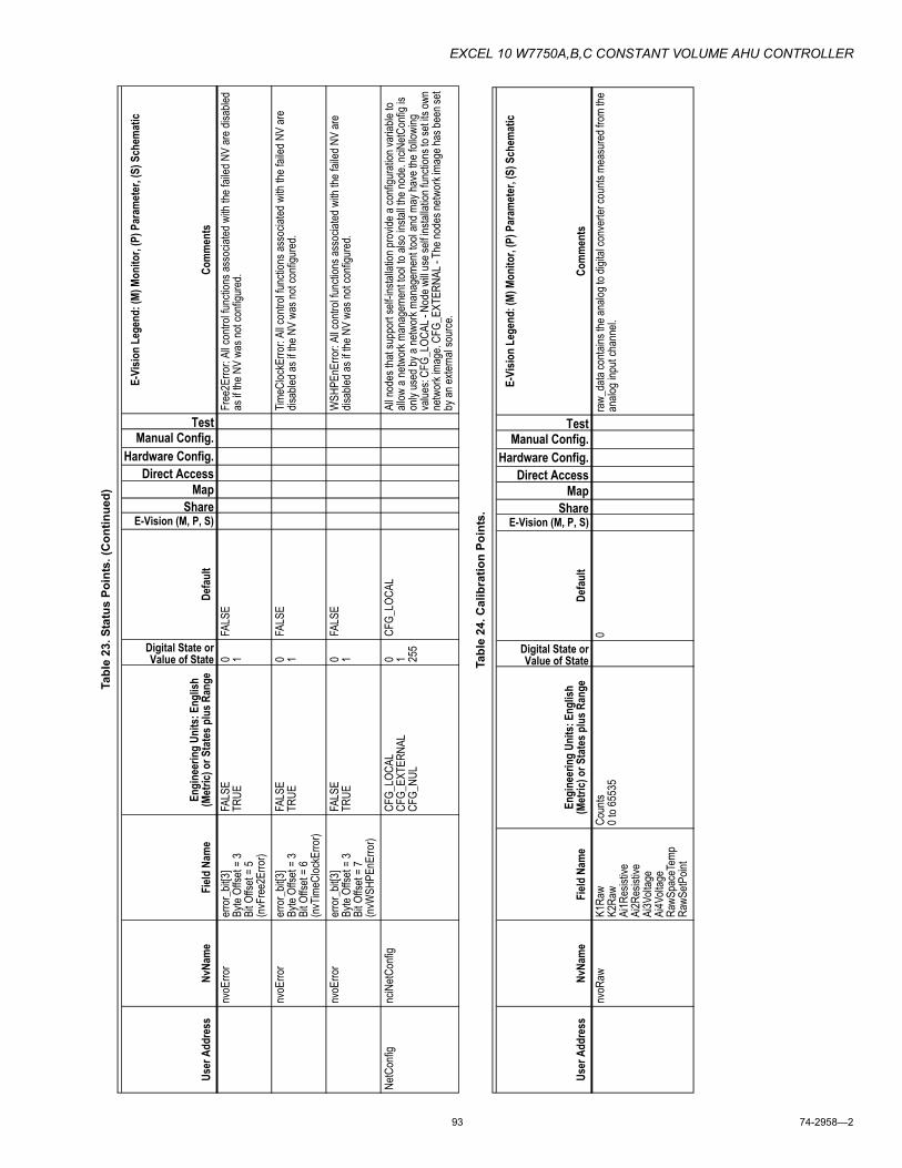
EXCEL 10 W7750A,B,C CONSTANT VOLUME AHU CONTROLLER
93 74-2958�2
nvoE
rror
erro
r_bit
[3]By
te Of
fset =
3Bi
t Offs
et =
5 (n
vFre
e2Er
ror)
FALS
ETR
UE0 1
FALS
EFr
ee2E
rror:
All c
ontro
l func
tions
asso
ciated
with
the f
ailed
NV
are d
isable
d as
if the
NV
was n
ot co
nfigu
red.
nvoE
rror
erro
r_bit
[3]By
te Of
fset =
3Bi
t Offs
et =
6 (n
vTim
eCloc
kErro
r)
FALS
ETR
UE0 1
FALS
ETim
eCloc
kErro
r: Al
l con
trol fu
nctio
ns as
socia
ted w
ith th
e fail
ed N
V ar
e dis
abled
as if
the N
V wa
s not
confi
gure
d.
nvoE
rror
erro
r_bit
[3]By
te Of
fset =
3Bi
t Offs
et =
7 (n
vWSH
PEnE
rror)
FALS
ETR
UE0 1
FALS
EW
SHPE
nErro
r: Al
l con
trol fu
nctio
ns as
socia
ted w
ith th
e fail
ed N
V ar
e dis
abled
as if
the N
V wa
s not
confi
gure
d.
NetC
onfig
nciN
etCon
figCF
G_LO
CAL
CFG_
EXTE
RNAL
CFG_
NUL
0 1 255
CFG_
LOCA
LAl
l nod
es th
at su
ppor
t self
-insta
llatio
n pro
vide a
confi
gura
tion v
ariab
le to
allow
a ne
twor
k man
agem
ent to
ol to
also i
nstal
l the n
ode.
nciN
etCon
fig is
on
ly us
ed by
a ne
twor
k man
agem
ent to
ol an
d may
have
the f
ollow
ing
value
s: CF
G_LO
CAL -
Nod
e will
use s
elf in
stalla
tion f
uncti
ons t
o set
its ow
n ne
twor
k ima
ge. C
FG_E
XTER
NAL -
The
node
s netw
ork i
mage
has b
een s
et by
an ex
terna
l sou
rce.
Tabl
e 24
. Cal
ibra
tion
Poin
ts.
User
Add
ress
NvNa
me
Field
Nam
eEn
gine
erin
g Un
its: E
nglis
h (M
etric
) or S
tate
s plu
s Ran
ge
Digital State or Value of State
Defa
ult
E-Vision (M, P, S)Share
Map Direct Access
Hardware Config.Manual Config.
Test
E-Vi
sion
Lege
nd: (
M) M
onito
r, (P
) Par
amet
er, (
S) S
chem
atic
Com
men
tsnv
oRaw
K1Ra
wK2
Raw
Ai1R
esist
iveAi
2Res
istive
Ai3V
oltag
eAi
4Volt
age
RawS
pace
Temp
RawS
etPoin
t
Coun
ts0 t
o 655
350
raw_
data
conta
ins th
e ana
log to
digit
al co
nver
ter co
unts
meas
ured
from
the
analo
g inp
ut ch
anne
l.
Tabl
e 23
. Sta
tus
Poin
ts. (
Con
tinue
d)
User
Add
ress
NvNa
me
Field
Nam
eEn
gine
erin
g Un
its: E
nglis
h (M
etric
) or S
tate
s plu
s Ran
ge
Digital State or Value of State
Defa
ult
E-Vision (M, P, S)Share
Map Direct Access
Hardware Config.Manual Config.
Test
E-Vi
sion
Lege
nd: (
M) M
onito
r, (P
) Par
amet
er, (
S) S
chem
atic
Com
men
ts

EXCEL 10 W7750A,B,C CONSTANT VOLUME AHU CONTROLLER
74-2958�2 94
Tabl
e 25
. Con
figur
atio
n Pa
ram
eter
s.
User
Add
ress
NvNa
me
Field
Nam
eEn
gine
erin
g Un
its: E
nglis
h (M
etric
) or S
tate
s plu
s Ran
ge
Digital State or Value of State
Defa
ult
E-Vision (M, P, S)Share
Map Direct Access
Hardware Config.Manual Config.
Test
E-Vi
sion
Lege
nd: (
M) M
onito
r, (P
) Par
amet
er, (
S) S
chem
atic
NOTE
: Phy
sical
I/O p
oint
s tha
t are
conf
igur
able
are i
n Ta
ble 2
0.
Com
men
tsnc
iDev
iceNa
meAS
CII B
lanks
Devic
eNam
e is a
n 18 c
hara
cter f
ield u
sed t
o ide
ntify
the no
de un
iquely
as
one o
bject
at the
site
or pr
oject.
The
conte
nts of
the D
evice
Name
is
maint
ained
by a
mana
geme
nt no
de. If
Dev
iceNa
me is
all A
SCII b
lanks
, it is
co
nside
red u
ncon
figur
ed.
nciA
pplVe
rap
plica
tion_
type
0 to 2
550
Appli
catio
nTyp
e ide
ntifie
s the
curre
nt ap
plica
tion n
umbe
r of th
e Exc
el 10
.nc
iApp
lVer
versi
on_n
o0 t
o 255
0Ve
rsion
Numb
er id
entifi
es th
e ver
sion n
umbe
r of th
e Exc
el 10
appli
catio
n.nc
iApp
lVer
time
Seco
nds
0Th
e tim
e stam
p of th
e las
t cha
nge t
o the
Exc
el 10
appli
catio
n co
nfigu
ratio
n. Tim
e mee
ts the
ANS
I C tim
e stam
p req
uirem
ent s
pecif
ying
the nu
mber
of se
cond
s elap
sed s
ince m
idnigh
t (0:0
0:00)
, Jan
uary
1, 19
70.
It is r
epre
sente
d in t
he In
tel F
orma
t.Fa
nMod
enc
iCon
figFa
nMod
eAU
TO_F
ANCO
NTIN
UOUS
_FAN
0 1AU
TO_F
ANP
XFa
nMod
e spe
cifies
the o
pera
tion o
f the f
an. If
the F
anMo
de is
0 (A
UTO_
FAN)
, then
the f
an cy
cles o
n and
off w
ith de
mand
for c
oolin
g and
ma
y cyc
le wi
th he
ating
if Fa
nOnH
eat is
TRU
E. If
the F
anMo
de is
1 (C
ONTI
NUOU
S_FA
N), th
en th
e fan
runs
conti
nuou
sly w
hen t
he ef
fectiv
e oc
cupa
ncy i
s OC_
OCCU
PIED
or O
C_BY
PASS
. The
fan c
ycles
on an
d off
with
dema
nd fo
r coo
ling a
nd m
ay cy
cle w
ith he
ating
if Fa
nOnH
eat is
TRU
E du
ring t
he O
C_UN
OCCU
PIED
or O
C_ST
ANDB
Y mo
des.
Econ
Mode
nciC
onfig
Econ
Enab
leDI
GITA
L_IN
OD_T
EMP
OD_E
NTH_
A_TY
PEOD
_ENT
H_B_
TYPE
OD_E
NTH_
C_TY
PEOD
_ENT
H_D_
TYPE
DIFF
_TEM
PSI
NGLE
_ENT
HDI
FF_E
NTH
ECON
_NUL
0 1 2 3 4 5 6 7 8 255
ECON
_NUL
PX
XEc
onEn
able
spec
ifies t
he m
ethod
used
to de
termi
ne w
hen o
utside
air is
su
itable
for u
se to
augm
ent c
oolin
g. Th
e vali
d valu
es ar
e acc
ordin
g to t
he
enum
erate
d list
that
is sh
own i
n the
Eng
ineer
ing U
nits/S
tates
colum
n.
SmkC
tlMod
enc
iCon
figSm
okeC
ontro
lFA
N_OF
F_DA
MPER
_CLO
SED
FAN_
ON_D
AMPE
R_OP
ENFA
N_ON
_DAM
PER_
CLOS
ED
0 1 2
FAN_
OFF_
DAMP
ER_
CLOS
EDP
XX
Smok
eCon
trol s
pecif
ies th
e ope
ratio
n of th
e eco
nomi
zer d
ampe
r and
the
fan w
hen t
he m
ode i
s SMO
KE_E
MERG
ENCY
.
HeatC
ycHr
nciC
onfig
ubHe
atCph
2 to 1
26
PX
XHe
atCph
spec
ifies t
he m
id-loa
d num
ber o
f on/o
ff cyc
les pe
r hou
r whe
n the
mo
de is
HEA
T. In
addit
ion th
e cyc
le ra
te sp
ecifie
s the
mini
mum
on an
d off
time.
Refer
to Ta
ble 17
Inter
stage
Mini
mum
Times
of th
e Sys
tem
Engin
eerin
g Guid
e for
the a
ctual
value
s.Co
olCyc
Hrnc
iCon
figub
CoolC
ph2 t
o 12
3P
XX
CoolC
ph sp
ecifie
s the
mid-
load n
umbe
r of o
n/off c
ycles
per h
our w
hen t
he
mode
is C
OOL.
In ad
dition
the c
ycle
rate
spec
ifies t
he m
inimu
m on
and o
ff tim
e. Re
fer to
Table
17 In
tersta
ge M
inimu
m Tim
es of
the S
ystem
En
ginee
ring G
uide f
or th
e actu
al va
lues.
FanR
unOn
Cool
nciC
onfig
ubFa
nRun
onCo
olS0
Seco
nds
0 to 1
200
PX
XFa
nRun
onCo
ol sp
ecifie
s how
long
the f
an ru
ns af
ter al
l the c
oolin
g stag
es
have
turn
ed of
f. The
fan i
s tur
ned o
ff Fan
Runo
nCoo
l sec
onds
after
all th
e co
oling
dema
nd ha
s tur
ned o
ff.Fa
nRun
OnHe
atnc
iCon
figub
FanR
unon
HeatS
0Se
cond
s0 t
o 120
0P
XX
FanR
unon
Heat
spec
ifies h
ow lo
ng th
e fan
runs
after
all th
e hea
ting s
tages
ha
ve tu
rned
off. T
he fa
n is t
urne
d off F
anRu
nonH
eat s
econ
ds af
ter al
l the
heati
ng de
mand
has t
urne
d off.

EXCEL 10 W7750A,B,C CONSTANT VOLUME AHU CONTROLLER
95 74-2958�2
Econ
MtrS
pdnc
iCon
figub
Econ
MtrT
imeS
0Se
cond
s20
to 24
090
PX
XEc
onMt
rTim
e spe
cifies
how
long i
t take
s the
econ
omize
r dam
per m
otor t
o tra
vel fr
om fu
lly cl
osed
to fu
lly op
en. T
his tim
e is u
sed t
o calc
ulate
the
repo
rted p
ositio
n of th
e dam
per a
nd to
deter
mine
the l
ength
of ov
er dr
ive
time r
equir
ed to
assu
re th
e dam
per is
fully
clos
ed or
open
.Co
olMtrS
pdnc
iCon
figub
CoolM
trTim
eS0
Seco
nds
20 to
240
90P
XX
CoolM
trTim
e spe
cifies
how
long i
t take
s the
cooli
ng da
mper
or va
lve m
otor
to tra
vel fr
om fu
lly cl
osed
to fu
lly op
en. T
his tim
e is u
sed t
o calc
ulate
the
repo
rted p
ositio
n of th
e coo
ling d
ampe
r or v
alve a
nd to
deter
mine
the
length
of ov
er dr
ive tim
e req
uired
to as
sure
that
it is f
ully c
losed
or op
en.
HeatM
trSpd
nciC
onfig
ubHe
atMtrT
imeS
0Se
cond
s20
to 24
090
PX
XHe
atMtrT
ime s
pecif
ies ho
w lon
g it ta
kes t
he he
ating
damp
er or
valve
moto
r to
trave
l from
fully
clos
ed to
fully
open
. This
time i
s use
d to c
alcula
te the
re
porte
d pos
ition o
f the h
eatin
g dam
per o
r valv
e and
to de
termi
ne th
e len
gth of
over
drive
time r
equir
ed to
assu
re th
at it i
s full
y clos
ed or
open
.Fa
nFail
Time
nciC
onfig
ubFa
nFail
TimeS
0Se
cond
s1 t
o 120
10P
XX
Each
time F
AN_O
UT is
ener
gized
, then
the n
ode w
aits f
or F
anFa
ilTim
e se
cond
s to s
ample
the P
roofA
irFlow
inpu
t. If P
roofA
irFlow
show
s tha
t the
fan is
not r
unnin
g for
Fan
FailT
ime c
onse
cutiv
e sec
onds
, then
the c
ontro
l is
shut
down
for t
he m
inimu
m off
time.
Then
the c
ontro
l (inc
luding
the f
an) is
re
starte
d and
Pro
ofAirF
low is
again
teste
d. If P
roofA
irFlow
show
s air f
low,
then t
he co
ntrol
conti
nues
to op
erate
, but
if Pro
ofAirF
low fa
ils to
show
air
flow,
then
the c
ontro
l is ag
ain sh
ut do
wn fo
r the
mini
mum
off tim
e. Af
ter
three
unsu
cces
sful re
starts
, a LO
SS_O
F_AI
R_FL
OW al
arm
is iss
ued a
nd
the co
ntrol
stays
in th
e DIS
ABLE
D mo
de w
ith th
e FAN
_OUT
off.
RmTe
mpCa
lnc
iCon
figsiS
pace
Temp
Zero
CalS
7De
gree
s F-5
to 5
(-3 to
3)0
XX
Spac
eTem
pZer
oCal
prov
ides o
ffset
calib
ratio
n for
the s
pace
analo
g sen
sor
input
and i
s add
ed to
the s
ense
d valu
e. Th
e ran
ge of
Spa
ceTe
mpZe
roCa
l is
betw
een -
5 and
5 de
gree
s F.
Temp
Offst
Cal1
nciC
onfig
siRes
istive
Offse
tCalS
7[0]
Degr
ees F
-15 t
o 15 (
-9 to
9)0
Resis
tiveO
ffsetC
al[0]
prov
ides o
ffset
calib
ratio
n for
the r
esist
ive an
alog
sens
or in
put a
nd is
adde
d to t
he se
nsed
value
. The
rang
e of
Resis
tiveO
ffsetC
al[0]
is be
twee
n -15
and 1
5 deg
rees
F.Te
mpOf
fstCa
l2nc
iCon
figsiR
esist
iveOf
fsetC
alS7[1
]De
gree
s F-1
5 to 1
5 (-9
to 9)
0Re
sistiv
eOffs
etCal[
1] pr
ovide
s offs
et ca
libra
tion f
or th
e res
istive
analo
g se
nsor
inpu
t and
is ad
ded t
o the
sens
ed va
lue. T
he ra
nge o
f Re
sistiv
eOffs
etCal[
1] is
betw
een -
15 an
d 15 d
egre
es F.
VoltO
ffstC
al1nc
iCon
figsiV
oltag
eOffs
etCalS
12[0]
volts
-1 to
10
Volta
geOf
fsetC
al[0]
prov
ides o
ffset
calib
ratio
n for
the v
oltag
e/cur
rent
analo
g sen
sor in
put a
nd is
adde
d to t
he se
nsed
value
. The
curre
nt an
alog
sens
or is
conv
erted
to a
volta
ge by
a 24
9 ohm
resis
ter w
ired a
cross
the
input
termi
nals.
The
rang
e of V
oltag
eOffs
etCal[
0] is
betw
een -
1 and
1 vo
lt. Vo
ltage
offse
ts ar
e new
in en
ginee
ring u
nits (
not v
olts).
VoltO
ffstC
al2nc
iCon
figsiV
oltag
eOffs
etCalS
12[1]
volts
-1 to
10
Volta
geOf
fsetC
al[1]
prov
ides o
ffset
calib
ratio
n for
the v
oltag
e/cur
rent
analo
g sen
sor in
put a
nd is
adde
d to t
he se
nsed
value
. The
curre
nt an
alog
sens
or is
conv
erted
to a
volta
ge by
a 24
9 ohm
resis
ter w
ired a
cross
the
input
termi
nals.
The
rang
e of V
oltag
eOffs
etCal[
1] is
betw
een -
1 and
1 vo
lt. Vo
ltage
offse
ts ar
e new
in en
ginee
ring u
nits (
not v
olts).
FanO
nHtM
ode
nciC
onfig
FanO
nHea
tFA
LSE
TRUE
0 1TR
UEP
XX
FanO
nHea
t spe
cifies
the o
pera
tion o
f the f
an du
ring H
EAT
mode
. If
FanO
nHea
t is 1(
TRUE
), the
n the
fan i
s on w
hen t
he m
ode i
s HEA
T. If
FanO
nHea
t is a
0 (FA
LSE)
the f
an is
neve
r tur
ned o
n whe
n the
mod
e is
HEAT
, and
typic
ally a
ther
mosta
ticall
y con
trolle
d swi
tch se
nsing
heate
d air
tempe
ratur
e tur
ns on
the f
an.
Tabl
e 25
. Con
figur
atio
n Pa
ram
eter
s. (C
ontin
ued)
User
Add
ress
NvNa
me
Field
Nam
eEn
gine
erin
g Un
its: E
nglis
h (M
etric
) or S
tate
s plu
s Ran
ge
Digital State or Value of State
Defa
ult
E-Vision (M, P, S)Share
Map Direct Access
Hardware Config.Manual Config.
Test
E-Vi
sion
Lege
nd: (
M) M
onito
r, (P
) Par
amet
er, (
S) S
chem
atic
NOTE
: Phy
sical
I/O p
oint
s tha
t are
conf
igur
able
are i
n Ta
ble 2
0.
Com
men
ts

EXCEL 10 W7750A,B,C CONSTANT VOLUME AHU CONTROLLER
74-2958�2 96
DisM
inHtT
ime
nciC
onfig
Disa
bleHe
atMinT
ime
FALS
ETR
UE0 1
FALS
EP
XX
If Disa
bleHe
atMinT
ime i
s 0 (F
ALSE
), the
heati
ng st
ages
are o
n or o
ff for
a mi
nimum
time d
eterm
ined b
y ubH
eatC
ph (R
efer t
o Tab
le 17
Inter
stage
Mi
nimum
Time
s of th
e Sys
tem E
ngine
ering
Guid
e). If
Disa
bleHe
atMinT
ime
is 1 (
TRUE
), the
heati
ng st
ages
are o
n or o
ff for
a 30
seco
nd m
inimu
m tim
e.Di
sMinC
lTime
nciC
onfig
Disa
bleCo
olMinT
ime
FALS
ETR
UE0 1
FALS
EP
XX
If Disa
bleCo
olMinT
ime i
s 0 (F
ALSE
), the
cooli
ng st
ages
are o
n or o
ff for
a mi
nimum
time d
eterm
ined b
y Coo
lCph
(Refe
r to T
able
17 In
tersta
ge
Minim
um Ti
mes o
f the S
ystem
Eng
ineer
ing G
uide)
. If D
isable
CoolM
inTim
e is
1 (TR
UE),
the co
oling
stag
es ar
e on o
r off f
or a
30 se
cond
mini
mum
time.
Casc
Cntrl
nciC
onfig
Casc
adeC
ontro
lFA
LSE
TRUE
0 1FA
LSE
PX
XW
hen C
asca
deCo
ntrol
is 0 (
FALS
E), th
en th
e disc
harg
e air t
empe
ratur
e is
not d
irectl
y con
trolle
d and
heati
ng an
d coo
ling e
quipm
ent a
re m
odula
ted to
ma
intain
spac
e tem
pera
ture.
Whe
n Cas
cade
Contr
ol is
1 (TR
UE),
then t
he
disch
arge
air t
empe
ratur
e is c
ontro
lled b
y an a
dditio
nal c
ontro
l loop
base
d on
the e
rror s
ignal
from
the sp
ace t
empe
ratur
e con
trol lo
op. C
asca
de
Contr
ol is
appli
cable
to m
odula
ting h
eatin
g/coo
ling o
nly (n
ot sta
ged)
.Us
eRaT
empC
tlnc
iCon
figCo
ntrolU
sesR
tnAirT
emp
FALS
ETR
UE0 1
FALS
EP
XX
If Con
trolU
sesR
tnAirT
emp i
s a 0
(FAL
SE),
then D
ata2.S
pace
Temp
is se
t eq
ual e
ither
the s
pace
temp
eratu
re se
nsor
(IO.
siSpa
ceTe
mp) o
r Sp
aceT
emp d
epen
ding o
n the
value
of S
pace
Temp
. Whe
n Co
ntrolU
sesR
tnAirT
emp i
s 1 (T
RUE)
and S
pace
Temp
is S
I_INV
ALID
, then
Da
ta2.S
pace
Temp
is se
t equ
al to
retur
n air s
enso
r (IO
.Retu
rnTe
mp) a
nd
the co
ntrol
uses
the r
eturn
air s
enso
r to c
ontro
l hea
ting o
r coo
ling.
Whe
n Co
ntrolU
sesR
tnAirT
emp i
s 1 (T
RUE)
and S
pace
Temp
is no
t SI_I
NVAL
ID,
then D
ata2.s
iSpa
ceTe
mp is
set e
qual
to Sp
aceT
emp a
nd th
e con
trol u
ses
Spac
eTem
p to c
ontro
l hea
ting o
r coo
ling.
IaqUs
eHea
tnc
iCon
figIaq
UseH
eat
FALS
ETR
UE0 1
FALS
EP
XX
Whe
n the
effec
tive o
ccup
ancy
is O
C_OC
CUPI
ED an
d Iaq
UseH
eat is
0 (F
ALSE
), the
n no h
eatin
g stag
es or
mod
ulatin
g hea
ting a
re tu
rned
whe
n the
disc
harg
e air t
empe
ratur
e goe
s belo
w the
low
limit.
Ener
gy ha
s prio
rity
over
venti
lation
. Whe
n the
effec
tive o
ccup
ancy
is O
C_OC
CUPI
ED an
d Iaq
UseH
eat is
1 (T
RUE)
, then
the h
eatin
g stag
es or
mod
ulatin
g hea
ting
are t
urne
d on t
o pre
vent
the di
scha
rge a
ir tem
pera
ture f
rom
going
below
the
disc
harg
e air t
empe
ratur
e low
limit.
Venti
lation
has p
riority
over
ener
gy
cost.
Tabl
e 25
. Con
figur
atio
n Pa
ram
eter
s. (C
ontin
ued)
User
Add
ress
NvNa
me
Field
Nam
eEn
gine
erin
g Un
its: E
nglis
h (M
etric
) or S
tate
s plu
s Ran
ge
Digital State or Value of State
Defa
ult
E-Vision (M, P, S)Share
Map Direct Access
Hardware Config.Manual Config.
Test
E-Vi
sion
Lege
nd: (
M) M
onito
r, (P
) Par
amet
er, (
S) S
chem
atic
NOTE
: Phy
sical
I/O p
oint
s tha
t are
conf
igur
able
are i
n Ta
ble 2
0.
Com
men
ts

EXCEL 10 W7750A,B,C CONSTANT VOLUME AHU CONTROLLER
97 74-2958�2
Ovrd
Prior
itync
iCon
figOv
errid
ePrio
rityLA
STNE
T0 1
NET
PX
XOv
errid
ePrio
rity co
nfigu
res t
he ov
errid
e arb
itratio
n betw
een M
anOc
c, By
pass
.state
, and
the w
all m
odule
over
ride b
utton
. If O
verri
dePr
iority
is 0
(LAS
T), th
en th
e las
t com
mand
rece
ived f
rom
eithe
r the
wall
mod
ule or
iM
anOc
c dete
rmine
s the
effec
tive o
verri
de st
ate. If
Ove
rride
Prior
ity is
1 (N
ET),
this s
pecif
ies th
at wh
en M
anOc
c is n
ot OC
_NUL
, that
the ef
fectiv
e oc
cupa
ncy i
s Man
Occ r
egar
dless
of th
e wall
mod
ule ov
errid
e stat
e.Us
eWall
ModS
tptnc
iCon
figUs
eWall
ModS
tPt
FALS
ETR
UE0 1
TRUE
PX
XUs
eWall
ModS
tpt sp
ecifie
s the
OC_
OCCU
PIED
temp
eratu
re se
tpoint
so
urce
. If U
seW
allMo
dStpt
is 0
(FAL
SE),
then t
he oc
cupie
d Tem
pSetP
ts ar
e use
d whe
n the
effec
tive o
ccup
ancy
is O
C_OC
CUPI
ED. If
Us
eWall
ModS
tpt is
1 (T
RUE)
, then
the w
all m
odule
s setp
oint k
nob i
s use
d wh
en th
e effe
ctive
occu
panc
y is O
C_OC
CUPI
ED. S
etPt o
verri
des a
ll.Se
tPtK
nob
nciC
onfig
SetP
ntKno
bOF
FSET
ABSO
LUTE
_MID
DLE
0 1AB
SOLU
TE_M
IDDL
EP
XX
SetP
ntKno
b spe
cifies
the u
sage
of th
e setp
oint k
nob w
hen
UseW
allMo
dStP
t is TR
UE. W
hen S
etPntK
nob i
s 0 (A
BSOL
UTE_
MIDD
LE),
the se
tpoint
knob
dire
ctly d
eterm
ines t
he ce
nter p
oint o
f betw
een t
he
OC_O
CCUP
IED
cooli
ng an
d hea
ting s
etpoin
ts. W
hen S
etPntK
nob i
s 1
(OFF
SET)
, the e
ffecti
ve se
tpoint
is ca
lculat
ed by
addin
g the
remo
te se
tpoint
poten
tiome
ter va
lue (c
enter
scale
= 0)
to th
e app
ropr
iate v
alue o
f Te
mpSe
tPts.
Ovrd
Type
nciC
onfig
Over
rideT
ype
NONE
NORM
ALBY
PASS
_ONL
Y
0 1 2
NORM
ALP
XX
Over
rideT
ype s
pecif
ies th
e beh
avior
of th
e ove
rride
butto
n. If t
he
Over
rideT
ype i
s 0 (N
ONE)
then
the o
verri
de bu
tton i
s disa
bled.
An
Over
rideT
ype o
f 1 (N
ORMA
L), c
ause
s the
over
ride b
utton
to se
t the
Over
Ride
state
to O
C_BY
PASS
for A
ux2S
etPt.B
ypas
sTim
e sec
onds
whe
n the
over
ride b
utton
has b
een p
ress
ed fo
r app
roxim
ately
1 to 4
seco
nds,
or
to se
t the O
verR
ide st
ate to
UNO
CC w
hen t
he bu
tton h
as be
en pr
esse
d for
ap
prox
imate
ly 4 t
o 7 se
cond
s. W
hen t
he bu
tton i
s pre
ssed
long
er th
an
appr
oxim
ately
7 sec
onds
, then
the O
verR
ide st
ate is
set to
OC_
NUL.
If the
Ov
errid
eTyp
e is 2
(BYP
ASS_
ONLY
), the
over
ride b
utton
sets
the O
verR
ide
state
to OC
_BYP
ASS
for A
ux2S
etPt.B
ypas
sTim
e sec
onds
on th
e firs
t pr
ess.
On th
e nex
t pre
ss, th
e Ove
rRide
state
is se
t to O
C_NU
L.
Tabl
e 25
. Con
figur
atio
n Pa
ram
eter
s. (C
ontin
ued)
User
Add
ress
NvNa
me
Field
Nam
eEn
gine
erin
g Un
its: E
nglis
h (M
etric
) or S
tate
s plu
s Ran
ge
Digital State or Value of State
Defa
ult
E-Vision (M, P, S)Share
Map Direct Access
Hardware Config.Manual Config.
Test
E-Vi
sion
Lege
nd: (
M) M
onito
r, (P
) Par
amet
er, (
S) S
chem
atic
NOTE
: Phy
sical
I/O p
oint
s tha
t are
conf
igur
able
are i
n Ta
ble 2
0.
Com
men
ts

EXCEL 10 W7750A,B,C CONSTANT VOLUME AHU CONTROLLER
74-2958�2 98
Tabl
e 26
. LO
NM
AR
K®
/Ope
n Sy
stem
Poi
nts.
User
Add
ress
NvNa
me
Field
Nam
eEn
gine
erin
g Un
its: E
nglis
h (M
etric
) or S
tate
s plu
s Ran
ge
Digital State or Value of State
Defa
ult
E-Vision (M, P, S)Share
Map Direct Access
Hardware Config.Manual Config.Failure Detect
E-Vi
sion
Lege
nd: (
M) M
onito
r, (P
) Par
amet
er, (
S) S
chem
atic
Com
men
tsnc
iNod
eSen
dT
(SNV
T_tim
e_se
c)Se
cond
s0
The m
axim
um tim
e betw
een u
pdate
s of n
etwor
k var
iable
outpu
ts fro
m the
no
de ob
ject.
nciR
tuSen
dT
(SNV
T_tim
e_se
c)Se
cond
s0
The S
GPUC
and S
GPU
time (
hear
t bea
t time
) betw
een u
pdate
s of n
etwor
k va
riable
outpu
ts.NO
TE: R
tuSen
dT sh
ould
be se
t to 55
seco
nds b
y a
mana
geme
nt no
de to
be co
mpati
ble w
ith a
Hone
ywell
syste
m.nc
iRtuR
cvT
(SNV
T_tim
e_se
c)Se
cond
s0
This
is the
failu
re de
tectio
n tim
e for
netw
ork S
GPUC
and S
GPU
varia
bles
outpu
ts.NO
TE: R
tuRcv
T sh
ould
be se
t to 30
0 sec
onds
by a
mana
geme
nt no
de to
be co
mpati
ble w
ith a
Hone
ywell
syste
m.Co
olOcc
Spt
nciTe
mpSe
tPts
(SNV
T_tem
p_se
tpt)
occu
pied_
cool
Degr
ees F
50 to
95De
gree
s C(1
0 to 3
5)
23P, M
XX
The C
oolin
g Occ
upied
Setp
oint is
used
if no
wall
mod
ule se
tpoint
pot is
co
nfigu
red a
s the
stan
dard
Occ
upied
Coo
ling S
etpoin
t. Actu
al Co
oling
Se
tpoint
can b
e affe
cted b
y var
ious c
ontro
l par
amete
rs (su
ch as
DlcS
hed,
SrcR
mtTe
mpSp
t, etc.
). Ac
tual ro
om te
mper
ature
Setp
oint is
refle
cted i
n Rm
Temp
ActS
pt. O
verri
dden
by nv
iSetP
t. Use
d to c
ompu
te ZE
B.Co
olStby
Spt
nciTe
mpSe
tPts
(SNV
T_tem
p_se
tpt)
stand
by_c
ool
Degr
ees F
50 to
95De
gree
s C(1
0 to 3
5)
25P, M
XX
Whe
n the
contr
oller
is in
the S
tandb
y mod
e (typ
ically
via a
n occ
upan
cy
sens
or),
the ba
se C
oolin
g Setp
oint is
deter
mine
d by t
he C
oolin
g Stan
dby
Setpo
int va
lue. A
lso, w
hen a
wall
mod
ule se
tpoint
pot is
confi
gure
d, thi
s va
lue se
rves a
s the
uppe
r limi
t on t
he us
er ad
justab
le re
mote
setpo
int po
t (w
all m
odule
).Co
olUno
ccSp
tnc
iTemp
SetP
ts (S
NVT_
temp_
setpt
)un
occu
pied_
cool
Degr
ees F
50 to
95De
gree
s C(1
0 to 3
5)
28P, M
XX
Whe
n the
contr
oller
is in
the U
nocc
upied
mod
e, the
unit r
espo
nds t
o a ca
ll for
cooli
ng ba
sed o
n the
Coo
ling U
nocc
upied
Setp
oint.
HeatO
ccSp
tnc
iTemp
SetP
ts (S
NVT_
temp_
setpt
)oc
cupie
d_he
atDe
gree
s F50
to 95
Degr
ees C
(10 t
o 35)
21P, M
XX
Whe
n the
contr
oller
is in
the O
ccup
ied m
ode,
if the
spac
e tem
pera
ture
drop
s belo
w the
Hea
ting O
ccup
ied S
etpoin
t, the
unit s
witch
es to
the
Heati
ng m
ode.
This
Setpo
int is
used
only
when
ther
e is n
o wall
mod
ule
setpo
int po
t con
figur
ed. O
verri
dden
by nv
iSetP
t. Use
d to c
ompu
te ZE
B.He
atStby
Spt
nciTe
mpSe
tPts
(SNV
T_tem
p_se
tpt)
stand
by_h
eat
Degr
ees F
50 to
95De
gree
s C(1
0 to 3
5)
19P, M
XX
Whe
n the
contr
oller
is in
the S
tandb
y mod
e (typ
ically
via a
n occ
upan
cy
sens
or),
the ba
se H
eatin
g Setp
oint is
deter
mine
d by t
he H
eatin
g Stan
dby
Setpo
int va
lue. A
lso, w
hen a
wall
mod
ule se
tpoint
pot is
confi
gure
d, thi
s va
lue se
rves a
s the
lowe
r limi
t on t
he us
er ad
justab
le re
mote
setpo
int po
t (w
all m
odule
).He
atUno
ccSp
tnc
iTemp
SetP
ts (S
NVT_
temp_
setpt
)un
occu
pied_
heat
Degr
ees F
50 to
95De
gree
s C(1
0 to 3
5)
16P, M
XX
Whe
n the
contr
oller
is in
the U
nocc
upied
mod
e, the
unit r
espo
nds t
o a ca
ll for
heati
ng ba
sed o
n the
Hea
ting U
nocc
upied
Setp
oint.
nviR
eque
st (S
NVT_
obj_r
eque
st)ob
ject_i
d0 t
o 655
351
Requ
est p
rovid
es th
e mec
hanis
m to
requ
est a
partic
ular s
tatus
repo
rt (vi
a St
atus)
for a
partic
ular o
bject
withi
n this
node
. Obje
ct_id
selec
ts the
objec
t be
ing re
feren
ced b
y nviR
eque
st. T
he on
ly va
lid va
lue of
objec
t_id i
s 1 fo
r the
RTU
objec
t and
all o
thers
are i
nvali
d.

EXCEL 10 W7750A,B,C CONSTANT VOLUME AHU CONTROLLER
99 74-2958�2
nviR
eque
st (S
NVT_
obj_r
eque
st)ob
ject_r
eque
stRQ
_NOR
MAL
RQ_D
ISAB
LED
RQ_U
PDAT
E_ST
ATUS
RQ_S
ELF_
TEST
RQ_U
PDAT
E_AL
ARM
RQ_R
EPOR
T_MA
SKRQ
_OVE
RRID
ERQ
_ENA
BLE
RQ_R
MV_O
VERR
IDE
RQ_C
LEAR
_STA
TUS
RQ_C
LEAR
_ALA
RMRQ
_NUL
0 1 2 3 4 5 6 7 8 9 10 255
RQ_N
ORMA
LW
hen o
bject_
requ
est is
RQ_
NORM
AL or
RQ_
UPDA
TE_S
TATU
S the
n the
sta
tus (v
ia St
atus)
will b
e rep
orted
for t
he ob
ject a
ddre
ssed
by ob
ject_i
d. W
hen o
bject_
requ
est is
RQ_
REPO
RT_M
ASK
then t
he st
atus b
its w
ill be
re
porte
d tha
t are
supp
orted
in nv
oStat
us by
the o
bject
addr
esse
d by
objec
t_id.
Bits
that a
re su
ppor
ted by
the o
bject
are s
et to
one.
All o
ther
objec
t_req
uest
items
are n
ot su
ppor
ted at
this
time a
nd w
ill re
turn a
n inv
alid_
requ
est (
Statu
s) in
the ob
ject s
tatus
.
DestH
vacM
ode
nviA
pplM
ode
(SNV
T_hv
ac_m
ode)
HVAC
_AUT
OHV
AC_H
EAT
HVAC
_MRN
G_W
RMUP
HVAC
_COO
LHV
AC_N
IGHT
_PUR
GEHV
AC_P
RE_C
OOL
HVAC
_OFF
HVAC
_TES
THV
AC_E
MERG
_HEA
THV
AC_F
AN_O
NLY
HVAC
_NUL
0 1 2 3 4 5 6 7 8 9 255
HVAC
_AUT
OM
XX
XX
XAp
plMod
e is a
n inp
ut tha
t coo
rdina
tes th
e roo
f top u
nit co
ntroll
er op
erati
on
with
other
contr
oller
s. HV
AC_N
IGHT
_PUR
GEHV
AC_P
RE_C
OOL
HVAC
_MRN
G_W
RMUP
HVAC
_NUL
HVAC
_TES
T ar
e not
supp
orted
and w
ill de
fault t
o the
HVA
C_AU
TO se
tting
if rec
eived
.
DestM
anOc
cnv
iMan
Occ
(SNV
T_oc
cupa
ncy)
OC_O
CCUP
IED
OC_U
NOCC
UPIE
DOC
_BYP
ASS
OC_S
TAND
BYOC
_NUL
0 1 2 3 255
OC_N
ULX
XX
ManO
cc is
an in
put fr
om a
netw
ork c
onne
cted o
pera
tor in
terfac
e or o
ther
node
that
indica
tes th
e stat
e of a
man
ual o
ccup
ancy
contr
ol thu
s ove
r rid
ing th
e sch
edule
d occ
upan
cy st
ate. M
anOc
c is u
sed a
long w
ith ot
her
occu
panc
y inp
uts to
calcu
late t
he ef
fectiv
e occ
upan
cy of
the n
ode.
See t
he
Data1
.Effe
ctOcc
and D
ata1.N
etMan
Occ f
or m
ore d
etails
.The
valid
en
umer
ated v
alues
have
the f
ollow
ing m
eanin
gs: O
C_OC
CUPI
ED
indica
tes oc
cupie
d. OC
_UNO
CCUP
IED
indica
tes no
t occ
upied
. OC
_BYP
ASS
indica
tes th
at the
spac
e is o
ccup
ied fo
r Au
x2Se
tPt.B
ypas
sTim
e sec
onds
after
Man
Occ i
s firs
t set
to OC
_BYP
ASS.
Th
e tim
ing is
done
by th
e byp
ass t
imer
in th
is no
de. If
Man
Occ c
hang
es to
an
other
value
the t
imer
is st
oppe
d.OC_
STAN
DBY
indica
tes th
at the
spac
e is
in sta
ndby
mod
e.OC_
NUL a
nd al
l uns
pecif
ied va
lues m
eans
that
no
manu
al oc
cupa
ncy c
ontro
l is re
ques
ted. W
hen M
anOc
c cha
nges
from
OC
_OCC
UPIE
D, O
C_UN
OCCU
PIED
, OC_
BYPA
SS, o
r OC_
STAN
DBY
to OC
_NUL
, any
bypa
ss co
nditio
n is c
ance
led.
DestR
mTem
pSpt
nviS
etPoin
t (S
NVT_
temp_
p)De
gree
s F50
to 95
Degr
ees C
(10 t
o 35)
SI_IN
VALID
XX
XSe
tPoin
t is an
inpu
t netw
ork v
ariab
le us
ed to
deter
mine
the t
empe
ratur
e co
ntrol
point
of th
e nod
e. If S
etPoin
t is no
t SI_I
NVAL
ID, th
en it
is us
ed to
de
termi
ne th
e con
trol p
oint o
f the n
ode.
If SetP
oint is
SI_I
NVAL
ID, th
en
other
mea
ns ar
e use
d to d
eterm
ine th
e con
trol p
oint. S
ee
Data2
.Temp
Contr
olPt fo
r mor
e info
rmati
on.
DestS
ptOffs
etnv
iSetP
tOffs
et (S
NVT_
temp_
p)De
gree
s F-1
8 to 1
8De
gree
s C-1
0 to 1
0
0X
XX
XSe
tPtO
ffset
is inp
ut fro
m an
oper
ator t
ermi
nal o
r fro
m an
ener
gy
mana
geme
nt sy
stem
used
to sh
ift the
effec
tive t
empe
ratur
e setp
oint b
y ad
ding S
etPtO
ffset
to the
othe
rwise
calcu
lated
setpo
int. If
the v
alue i
s ou
tside
the a
llowe
d ran
ge of
-10 t
o +10
degr
ees C
(-18
to 18
degr
ees F
), the
n the
node
uses
the v
alue o
f the n
eare
st ra
nge l
imit.
Tabl
e 26
. LO
NM
AR
K®
/Ope
n Sy
stem
Poi
nts.
(Con
tinue
d)
User
Add
ress
NvNa
me
Field
Nam
eEn
gine
erin
g Un
its: E
nglis
h (M
etric
) or S
tate
s plu
s Ran
ge
Digital State or Value of State
Defa
ult
E-Vision (M, P, S)Share
Map Direct Access
Hardware Config.Manual Config.Failure Detect
E-Vi
sion
Lege
nd: (
M) M
onito
r, (P
) Par
amet
er, (
S) S
chem
atic
Com
men
ts

EXCEL 10 W7750A,B,C CONSTANT VOLUME AHU CONTROLLER
74-2958�2 100
SrcR
mTem
pActS
ptnv
oEffe
ctSetP
t (S
NVT_
temp_
p)De
gree
s F50
to 95
Degr
ees C
(10 t
o 35)
SI_IN
VALID
XX
Effec
tSetP
t is th
e cur
rent
tempe
ratur
e con
trol p
oint (
such
that
the cu
rrent
actua
l spa
ce te
mper
ature
setpo
int w
hich t
he co
ntroll
er is
pres
ently
tryin
g to
maint
ain in
the c
ondit
ioned
spac
e). S
ee D
ata2.T
empC
ontro
lPt fo
r mor
e de
tails.
Effe
ctSetP
t is up
dated
acco
rding
to th
e SGP
U me
chan
ism w
here
a sig
nifica
nt ch
ange
is pl
us or
minu
s 0.07
degr
ees C
(0.13
degr
ees F
).De
stRmT
emp
nviS
pace
Temp
(S
NVT_
temp_
p)De
gree
s F14
to 12
2De
gree
s C(-1
0 to 5
0)
SI_IN
VALID
XX
XX
Spac
eTem
p is t
he sp
ace t
empe
ratur
e sen
sed b
y ano
ther n
ode a
nd is
typ
ically
boun
d to S
pace
Temp
of an
other
node
havin
g a sp
ace t
empe
ratur
e se
nsor.
If Sp
aceT
emp h
as a
value
othe
r tha
n SI_I
NVAL
ID it
is us
ed as
the
sens
ed sp
ace t
empe
ratur
e by t
he no
de ra
ther t
han u
sing a
ny lo
cal h
ard-
wire
d sen
sor. I
f the v
alue i
s outs
ide th
e allo
wed r
ange
of -1
0 to 5
0 deg
rees
C
(-18 t
o 90 d
egre
es F
), the
n the
node
uses
the v
alue o
f the n
eare
st ra
nge
limit.
Whe
n Spa
ceTe
mp is
not b
ound
to an
other
node
, Spa
ceTe
mp m
ay be
us
ed to
fix th
e sen
sed t
empe
ratur
e. A
mana
geme
nt no
de m
ay w
rite a
value
oth
er th
an S
I_INV
ALID
, cau
sing t
he no
de to
use S
pace
Temp
inste
ad of
the
hard
-wire
d sen
sor. A
n app
licati
on re
start
or po
wer f
ailur
e cau
ses t
he fix
ed
sens
or va
lue to
be fo
rgott
en an
d Spa
ceTe
mp to
be re
turne
d to
SI_IN
VALID
.Sr
cRmT
emp
nvoS
pace
Temp
(S
NVT_
temp_
p)De
gree
s F14
to 12
2De
gree
s C(-1
0 to 5
0)
SI_IN
VALID
XX
Spac
eTem
p is t
he se
nsed
spac
e tem
pera
ture f
rom
the lo
cally
wire
d sen
sor.
Spac
eTem
p is t
ypica
lly bo
und t
o Spa
ceTe
mp of
anoth
er no
de w
hich m
ay
not h
ave i
ts ow
n spa
ce te
mper
ature
sens
or bu
t con
trol th
e sam
e spa
ce.
The r
epor
ted sp
ace t
empe
ratur
e inc
ludes
the o
ffset
corre
ction
Co
nfig.S
pace
Temp
Zero
Cal. I
f the s
pace
temp
eratu
re se
nsor
is no
t co
nnec
ted or
is sh
orted
, or if
Spa
ceTe
mp is
boun
d to a
nothe
r nod
e, the
n Sp
aceT
emp i
s set
to SI
_INVA
LID.
DestO
aTem
pnv
iOdT
emp
(SNV
T_tem
p_p)
Degr
ees F
-40 t
o 122
Degr
ees C
(-40 t
o 50)
SI_IN
VALID
MX
XX
XOd
Temp
allow
s one
outsi
de ai
r tem
pera
ture s
enso
r at a
node
to be
shar
ed
by m
any o
ther n
odes
. Whe
n OdT
emp i
s not
SI_IN
VALID
, then
any l
ocal
sens
or is
igno
red b
y the
loca
l con
trol a
lgorith
m an
d OdT
emp i
s use
d ins
tead.
If the
value
is ou
tside
the a
llowe
d ran
ge of
-40 t
o 50 d
egre
es C
(-72
to 90
degr
ees F
), the
n the
node
uses
the v
alue o
f the n
eare
st ra
nge
limit.
SrcO
aTem
pnv
oOdT
emp
(SNV
T_tem
p_p)
Degr
ees F
-40 t
o 122
Degr
ees C
(-40 t
o 50)
SI_IN
VALID
MX
XOd
Temp
allow
s the
loca
l outd
oor t
empe
ratur
e sen
sor t
o be s
hare
d with
oth
er no
des a
nd is
typic
ally b
ound
to O
dTem
p on o
ther n
odes
. If th
e loc
al se
nsor
is co
nfigu
red b
y Sele
ct, O
dTem
p is p
eriod
ically
sent
on th
e netw
ork.
If the
loca
l sen
sor is
not c
onfig
ured
or cu
rrentl
y sho
wing
an er
ror, t
he va
lue
is SI
_INVA
LID.
DestO
aHum
nviO
dHum
(S
NVT_
lev_p
erce
nt)Pe
rcenta
ge10
to 90
SI_IN
VALID
MX
XX
XOd
Hum
allow
s one
outdo
or hu
midit
y sen
sor a
t a no
de to
be sh
ared
by
many
othe
r nod
es. W
hen n
viOdH
um is
not S
I_INV
ALID
, then
the l
ocal
sens
or, is
igno
red b
y the
loca
l con
trol a
lgorith
m an
d OdH
um is
used
ins
tead.
If the
value
is ou
tside
the a
llowe
d ran
ge (1
0 to 9
0 per
cent)
, then
the
node
uses
the v
alue o
f the n
eare
st ra
nge l
imit.
SrcO
aHum
nvoO
dHum
(S
NVT_
lev_p
erce
nt)Pe
rcenta
ge10
to 90
SI_IN
VALID
MX
XOd
Hum
allow
s the
loca
l outd
oor h
umidi
ty se
nsor
to be
shar
ed w
ith ot
her
node
s and
is ty
picall
y bou
nd to
OdH
um on
othe
r nod
es. If
the l
ocal
sens
or
is co
nfigu
red b
y Sele
ct, O
dHum
is pe
riodic
ally s
ent o
n the
netw
ork.
If the
loc
al se
nsor
is no
t con
figur
ed or
curre
ntly s
howi
ng an
erro
r, the
value
is
SI_IN
VALID
.
Tabl
e 26
. LO
NM
AR
K®
/Ope
n Sy
stem
Poi
nts.
(Con
tinue
d)
User
Add
ress
NvNa
me
Field
Nam
eEn
gine
erin
g Un
its: E
nglis
h (M
etric
) or S
tate
s plu
s Ran
ge
Digital State or Value of State
Defa
ult
E-Vision (M, P, S)Share
Map Direct Access
Hardware Config.Manual Config.Failure Detect
E-Vi
sion
Lege
nd: (
M) M
onito
r, (P
) Par
amet
er, (
S) S
chem
atic
Com
men
ts

EXCEL 10 W7750A,B,C CONSTANT VOLUME AHU CONTROLLER
101 74-2958�2
DestE
merg
Cmd
nviE
merg
(S
NVT_
hvac
_eme
rg)
EMER
G_NO
RMAL
EMER
G_PR
ESSU
RIZE
EMER
G_DE
PRES
SURI
ZEEM
ERG_
PURG
EEM
ERG_
SHUT
DOW
NEM
ERG_
NUL
0 1 2 3 4 255
EMER
G_NO
RMAL
MX
XX
XEm
erg i
s an e
merg
ency
inpu
t from
a de
vice t
hat d
eterm
ines t
he co
rrect
actio
n dur
ing a
given
emer
genc
y (su
ch as
a fire
). If E
merg
is
EMER
G_NO
RMAL
the f
an an
d eco
nomi
zer d
ampe
r are
contr
olled
by th
e he
ating
and c
oolin
g con
trol a
lgorith
m. If
Emer
g is E
MERG
_PRE
SSUR
IZE,
the
n the
fan i
s con
trolle
d on a
nd th
e eco
nomi
zer d
ampe
r is op
en. If
Eme
rg
is EM
ERG_
DEPR
ESSU
RIZE
, then
the f
an is
contr
olled
on an
d the
ec
onom
izer d
ampe
r is cl
osed
. If E
merg
is E
MERG
_SHU
TDOW
N, th
en th
e fan
is co
ntroll
ed of
f and
the e
cono
mize
r dam
per is
clos
ed. If
Eme
rg is
EM
ERG_
PURG
E, th
e fan
and d
ampe
r go t
o the
state
spec
ified b
y Co
nfig.S
moke
Contr
ol. If
Emer
g is n
ot co
nfigu
red t
hen i
t is se
t to
EMER
G_NU
L.Sr
cUnit
Statu
snv
oUnit
Statu
s (S
NVT_
hvac
_stat
us)
mode
HVAC
_AUT
OHV
AC_H
EAT
HVAC
_MRN
G_W
RMUP
HVAC
_COO
LHV
AC_N
IGHT
_PUR
GEHV
AC_P
RE_C
OOL
HVAC
_OFF
HVAC
_TES
THV
AC_E
MERG
_HEA
THV
AC_F
AN_O
NLY
HVAC
_NUL
0 1 2 3 4 5 6 7 8 9 255
HVAC
_NUL
MX
XMo
de is
set a
ccor
ding t
o the
Data
1.mod
e. If D
ata1.m
ode i
s ST
ART_
UP_W
AIT,
SMOK
E_EM
ERGE
NCY,
or FR
EEZE
_PRO
TECT
, mod
e is
set to
HVA
C_NU
L whic
h ind
icates
that
the no
de is
in a
mode
not
supp
orted
by th
e SNV
T_hv
ac_m
ode d
ata ty
pe. If
Data
1.mod
e is H
EAT,
then m
ode i
s set
to HV
AC_H
EAT
which
indic
ates t
hat h
eatin
g ene
rgy i
s be
ing su
pplie
d to t
he co
ntroll
ed sp
ace.
If Data
1.mod
e is C
OOL,
then m
ode
is se
t to H
VAC_
COOL
, whic
h ind
icates
that
cooli
ng en
ergy
is be
ing
supp
lied t
o the
contr
olled
spac
e. If D
ata1.m
ode i
s OFF
_MOD
E or
DI
SABL
ED_M
ODE,
then
mod
e is s
et to
HVAC
_OFF
whic
h ind
icates
that
the no
de is
not r
unnin
g its
norm
al tem
pera
ture c
ontro
l and
the o
utputs
are
not tu
rned
off. I
f Data
1.mod
e is E
MERG
_HEA
T, mo
de is
set to
HV
AC_E
MERG
_HEA
T wh
ere,
in a h
eat p
ump a
pplic
ation
, the c
ompr
esso
r sta
ges a
re di
sable
d and
only
auxil
iary h
eatin
g stag
es ar
e tur
ned o
n. If
Data1
.mod
e is M
ANUA
L or F
ACTO
RY_T
EST,
mode
is se
t to H
VAC_
TEST
wh
ich in
dicate
s tha
t the n
ode i
s in a
man
ual o
r tes
t mod
e. If D
ata1.m
ode i
s FA
N_ON
LY, m
ode i
s set
to HV
AC_F
AN_O
NLY
which
indic
ates t
hat th
e fan
is
runn
ing bu
t the s
pace
temp
eratu
re co
ntrol
is tur
ned o
ff.nv
oUnit
Statu
s (S
NVT_
hvac
_stat
us)
heat_
outpu
t_prim
ary
Perce
ntage
0 to 1
000
heat_
outpu
t_prim
ary r
epor
ts the
curre
nt pe
rcenta
ge of
heati
ng st
ages
or
modu
lating
heat
turne
d on.
If the
node
is co
ntroll
ing a
heat
pump
, he
at_ou
tput_p
rimar
y rep
orts
the cu
rrent
perce
ntage
of co
mpre
ssor
stag
es
turne
d on w
hen t
he no
de is
in th
e HVA
C_HE
AT m
ode.
nvoU
nitSt
atus
(SNV
T_hv
ac_s
tatus
)he
at_ou
tput_s
econ
dary
Perce
ntage
0 to 1
000
If the
node
is co
ntroll
ing a
heat
pump
, hea
t_outp
ut_se
cond
ary r
epor
ts the
cu
rrent
perce
ntage
of au
xiliar
y hea
ting s
tages
turn
ed on
whe
n the
node
is
in the
HVA
C_HE
AT or
HVA
C_EM
ERG_
HEAT
mod
e. If t
he no
de is
not
contr
olling
a he
at pu
mp, h
eat_o
utput_
seco
ndar
y is s
et to
zero
.nv
oUnit
Statu
s (S
NVT_
hvac
_stat
us)
cool_
outpu
tPe
rcenta
ge0 t
o 100
0co
ol_ou
tput r
epor
ts the
curre
nt pe
rcenta
ge of
cooli
ng st
ages
or m
odula
ting
cool
turne
d on.
If the
node
is co
ntroll
ing a
heat
pump
, coo
l_outp
ut re
ports
the
curre
nt pe
rcenta
ge of
comp
ress
or st
ages
turn
ed on
whe
n the
node
is in
the
HVA
C_CO
OL m
ode.
nvoU
nitSt
atus
(SNV
T_hv
ac_s
tatus
)ec
on_o
utput
Perce
ntage
0 to 1
000
If the
re is
a mo
dulat
ing ec
onom
izer c
onfig
ured
, eco
n_ou
tput r
epor
ts the
pe
rcenta
ge th
at the
econ
omize
r dam
per is
open
ed. If
no ec
onom
izer is
co
nfigu
red,
econ
_outp
ut re
ports
0.nv
oUnit
Statu
s (S
NVT_
hvac
_stat
us)
fan_o
utput
Perce
ntage
0 to 1
000
Whe
n the
fan i
s run
ning,
fan_o
utput
is 10
0 per
cent,
and w
hen t
he fa
n is n
ot ru
nning
, fan_
outpu
t is 0
perce
nt.
Tabl
e 26
. LO
NM
AR
K®
/Ope
n Sy
stem
Poi
nts.
(Con
tinue
d)
User
Add
ress
NvNa
me
Field
Nam
eEn
gine
erin
g Un
its: E
nglis
h (M
etric
) or S
tate
s plu
s Ran
ge
Digital State or Value of State
Defa
ult
E-Vision (M, P, S)Share
Map Direct Access
Hardware Config.Manual Config.Failure Detect
E-Vi
sion
Lege
nd: (
M) M
onito
r, (P
) Par
amet
er, (
S) S
chem
atic
Com
men
ts

EXCEL 10 W7750A,B,C CONSTANT VOLUME AHU CONTROLLER
74-2958�2 102
nvoU
nitSt
atus
(SNV
T_hv
ac_s
tatus
)in_
alarm
FALS
ETR
UEAL
ARM_
NOTI
FY_D
ISAB
LED
0 1 255
FALS
EW
hen t
here
is an
alar
m re
porte
d by A
larmS
tatus
, then
in_a
larm
is se
t to 1
(TRU
E), e
lse in
_alar
m is
set to
0 (F
ALSE
). If a
larms
repo
rting i
s su
ppre
ssed
via M
anua
lMod
e, the
n in_
alarm
is se
t to
ALAR
M_NO
TIFY
_DIS
ABLE
D.nv
iInUs
e(un
signe
d lon
g)0 T
o 655
350 t
o FFF
FInU
se is
used
by a
mana
geme
nt no
de to
indic
ate to
all o
ther m
anag
emen
t no
des t
hat it
is lo
gged
on to
the E
xcel
10 no
de an
d tha
t they
shou
ld no
t try
to int
erac
t with
any o
f the E
xcel
10s n
etwor
k var
iables
. Befo
re th
e ma
nage
ment
node
read
s or w
rites a
ny ne
twor
k var
iables
, the m
anag
emen
t no
de ch
ecks
nviIn
Use f
or a
zero
value
mea
ning n
o othe
r man
agem
ent
node
s are
alre
ady l
ogge
d on a
nd th
at a m
anag
emen
t nod
e may
log o
n to
the no
de. T
hen t
he m
anag
emen
t nod
e write
s a nu
mber,
1 thr
ough
6553
4, to
nviIn
Use a
nd pe
riodic
ally w
rites t
he sa
me va
lue to
indic
ate th
at the
ma
nage
ment
node
is st
ill log
ged o
n. If t
here
are n
o write
s mad
e to
nviIn
Use f
or ap
prox
imate
ly 60
seco
nds,
then t
he E
xcel
10 re
sets
nviIn
Use
to ze
ro to
autom
atica
lly lo
g off t
he m
anag
emen
t nod
e. Be
fore i
ntera
cting
wi
th an
y netw
ork v
ariab
les, th
e man
agem
ent n
ode v
erifie
s tha
t the
nviIn
Use h
as no
t cha
nged
. The
man
agem
ent n
ode l
ogs o
ff by w
riting
0 to
nviIn
Use.D
uring
powe
r up,
an ap
plica
tion r
estar
t, or r
eturn
to on
-line f
rom
off-lin
e, the
Exc
el 10
sets
InUse
to 65
535 t
o ind
icate
to the
man
agem
ent
node
that
it has
retur
ned t
o on-
line.
nvoS
tatus
(S
NVT_
obj_r
eque
st)ob
ject_i
d0 t
o 655
350
MX
objec
t_id i
s set
to the
curre
nt va
lue of
nviR
eque
st.ob
ject_i
d
nvoS
tatus
(S
NVT_
obj_r
eque
st)inv
alid_
idFA
LSE
TRUE
0 1FA
LSE
If Req
uest.
Objec
t_id i
s not
a vali
d obje
ct, in
valid
_id is
set to
1 (T
RUE)
oth
erwi
se it
is se
t to 0
(FAL
SE).
nvoS
tatus
(S
NVT_
obj_r
eque
st)inv
alid_
requ
est
FALS
ETR
UE0 1
FALS
EIf R
eque
st.ob
ject_r
eque
st is
not a
valid
requ
est fo
r the
objec
t add
ress
ed,
invali
d_re
ques
t is se
t to 1
(TRU
E) ot
herw
ise it
is se
t to 0
(FAL
SE).
nvoS
tatus
(S
NVT_
obj_r
eque
st)dis
abled
FALS
ETR
UE0 1
FALS
ETh
e disa
bled f
ield i
s not
supp
orted
and i
s set
to 0 (
FALS
E) un
less
Requ
est.o
bject_
requ
est is
RQ_
REPO
RT_M
ASK,
then
disa
bled a
nd
in_ala
rm ar
e set
to 1 (
TRUE
) to i
ndica
te tha
t thes
e fun
ction
s are
supp
orted
wh
ile al
l othe
r fiel
ds ar
e set
to 0 (
FALS
E).
nvoS
tatus
(S
NVT_
obj_r
eque
st)ou
t_of_l
imits
FALS
ETR
UE0 1
FALS
ETh
e out_
of_lim
its fie
ld is
not s
uppo
rted a
nd is
set to
0 (F
ALSE
).
nvoS
tatus
(S
NVT_
obj_r
eque
st)op
en_c
ircuit
FALS
ETR
UE0 1
FALS
ETh
e ope
n_cir
cuit f
ield i
s not
supp
orted
and i
s set
to 0 (
FALS
E).
nvoS
tatus
(S
NVT_
obj_r
eque
st)ou
t_of_s
ervic
eFA
LSE
TRUE
0 1FA
LSE
The o
ut_of_
servi
ce fie
ld is
not s
uppo
rted a
nd is
set to
0 (F
ALSE
).
nvoS
tatus
(S
NVT_
obj_r
eque
st)me
chan
ical_f
ault
FALS
ETR
UE0 1
FALS
ETh
e mec
hanic
al_fau
lt fiel
d is n
ot su
ppor
ted an
d is s
et to
0 (FA
LSE)
.
nvoS
tatus
(S
NVT_
obj_r
eque
st)fee
dbac
k_fai
lure
FALS
ETR
UE0 1
FALS
ETh
e fee
dbac
k_fai
lure f
ield i
s not
supp
orted
and i
s set
to 0 (
FALS
E).
nvoS
tatus
(S
NVT_
obj_r
eque
st)ov
er_r
ange
FALS
ETR
UE0 1
FALS
ETh
e ove
r_ra
nge f
ield i
s not
supp
orted
and i
s set
to 0 (
FALS
E).
nvoS
tatus
(S
NVT_
obj_r
eque
st)un
der_
rang
eFA
LSE
TRUE
0 1FA
LSE
The u
nder
_ran
ge fie
ld is
not s
uppo
rted a
nd is
set to
0 (F
ALSE
).
Tabl
e 26
. LO
NM
AR
K®
/Ope
n Sy
stem
Poi
nts.
(Con
tinue
d)
User
Add
ress
NvNa
me
Field
Nam
eEn
gine
erin
g Un
its: E
nglis
h (M
etric
) or S
tate
s plu
s Ran
ge
Digital State or Value of State
Defa
ult
E-Vision (M, P, S)Share
Map Direct Access
Hardware Config.Manual Config.Failure Detect
E-Vi
sion
Lege
nd: (
M) M
onito
r, (P
) Par
amet
er, (
S) S
chem
atic
Com
men
ts
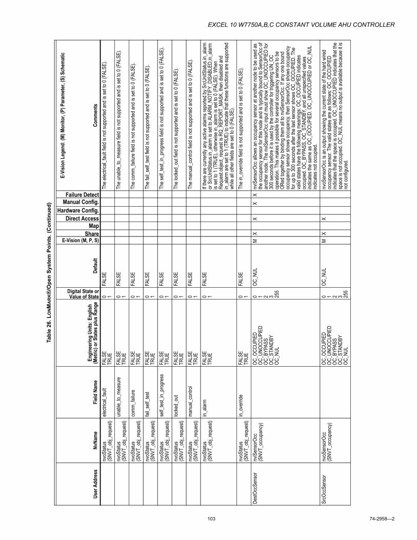
EXCEL 10 W7750A,B,C CONSTANT VOLUME AHU CONTROLLER
103 74-2958�2
nvoS
tatus
(S
NVT_
obj_r
eque
st)ele
ctrica
l_fau
ltFA
LSE
TRUE
0 1FA
LSE
The e
lectric
al_fau
lt fiel
d is n
ot su
ppor
ted an
d is s
et to
0 (FA
LSE)
.
nvoS
tatus
(S
NVT_
obj_r
eque
st)un
able_
to_me
asur
eFA
LSE
TRUE
0 1FA
LSE
The u
nable
_to_m
easu
re fie
ld is
not s
uppo
rted a
nd is
set to
0 (F
ALSE
).
nvoS
tatus
(S
NVT_
obj_r
eque
st)co
mm_fa
ilure
FALS
ETR
UE0 1
FALS
ETh
e com
m_fai
lure f
ield i
s not
supp
orted
and i
s set
to 0 (
FALS
E).
nvoS
tatus
(S
NVT_
obj_r
eque
st)fai
l_self
_test
FALS
ETR
UE0 1
FALS
ETh
e fail
_self
_test
field
is no
t sup
porte
d and
is se
t to 0
(FAL
SE).
nvoS
tatus
(S
NVT_
obj_r
eque
st)se
lf_tes
t_in_
prog
ress
FALS
ETR
UE0 1
FALS
ETh
e self
_test_
in_pr
ogre
ss fie
ld is
not s
uppo
rted a
nd is
set to
0 (F
ALSE
).
nvoS
tatus
(S
NVT_
obj_r
eque
st)loc
ked_
out
FALS
ETR
UE0 1
FALS
ETh
e loc
ked_
out fi
eld is
not s
uppo
rted a
nd is
set to
0 (F
ALSE
).
nvoS
tatus
(S
NVT_
obj_r
eque
st)ma
nual_
contr
olFA
LSE
TRUE
0 1FA
LSE
The m
anua
l_con
trol fi
eld is
not s
uppo
rted a
nd is
set to
0 (F
ALSE
).
nvoS
tatus
(S
NVT_
obj_r
eque
st)in_
alarm
FALS
ETR
UE0 1
FALS
EIf t
here
are c
urre
ntly a
ny ac
tive a
larms
repo
rted b
y SrcU
nitSt
atus.i
n_ala
rm
or S
rcUnit
Statu
s.in_
alarm
is se
t to A
LARM
_NOT
IFY_
DISA
BLED
,in_a
larm
is se
t to 1
(TRU
E), o
therw
ise in
_alar
m is
set to
0 (F
ALSE
). W
hen
Requ
est.o
bject_
requ
est is
RQ_
REPO
RT_M
ASK,
then
disa
bled a
nd
in_ala
rm ar
e set
to 1 (
TRUE
) to i
ndica
te tha
t thes
e fun
ction
s are
supp
orted
wh
ile al
l othe
r fiel
ds ar
e set
to 0 (
FALS
E).
nvoS
tatus
(S
NVT_
obj_r
eque
st)in_
over
ride
FALS
ETR
UE0 1
FALS
ETh
e in_
over
ride f
ield i
s not
supp
orted
and i
s set
to 0 (
FALS
E).
DestO
ccSe
nsor
nviS
enso
rOcc
(S
NVT_
occu
panc
y)OC
_OCC
UPIE
DOC
_UNO
CCUP
IED
OC_B
YPAS
SOC
_STA
NDBY
OC_N
UL
0 1 2 3 255
OC_N
ULM
XX
XX
nviS
enso
rOcc
allow
s an o
ccup
ancy
sens
or at
anoth
er no
de to
be us
ed as
the
occu
panc
y sen
sor f
or th
is no
de an
d is t
ypica
lly bo
und t
o Sen
sorO
cc of
an
other
node
. The
nviS
enso
rOcc
inpu
t mus
t sho
w OC
_UNO
CCUP
IED
for
300 s
econ
ds be
fore i
t is us
ed by
the c
ontro
ller f
or tr
igger
ing U
N_OC
op
erati
on. T
his m
akes
it po
ssibl
e for
seve
ral o
ccup
ancy
sens
ors t
o be
ORed
toge
ther b
y bind
ing th
em al
l to nv
iSen
sorO
cc. If
any o
ne bo
und
occu
panc
y sen
sor s
hows
occu
panc
y, the
n Sen
sorO
cc sh
ows o
ccup
ancy
for
up to
300 s
econ
ds af
ter th
e las
t sen
sor s
hows
OC_
OCCU
PIED
. The
va
lid st
ates h
ave t
he fo
llowi
ng m
eanin
gs: O
C_OC
CUPI
ED in
dicate
s oc
cupie
d. OC
_BYP
ASS,
OC_
STAN
DBY,
and a
ll uns
pecif
ied va
lues
indica
tes th
e sam
e as O
C_OC
CUPI
ED. O
C_UN
OCCU
PIED
or O
C_NU
L ind
icates
not o
ccup
ied.
SrcO
ccSe
nsor
nvoS
enso
rOcc
(S
NVT_
occu
panc
y)OC
_OCC
UPIE
DOC
_UNO
CCUP
IED
OC_B
YPAS
SOC
_STA
NDBY
OC_N
UL
0 1 2 3 255
OC_N
ULM
XX
nvoS
enso
rOcc
is an
outpu
t sho
wing
the c
urre
nt sta
te of
the ha
rd w
ired
occu
panc
y sen
sor. T
he va
lid st
ates a
re as
follo
ws: O
C_OC
CUPI
ED
indica
tes th
at the
spac
e is o
ccup
ied. O
C_UN
OCCU
PIED
indic
ates t
hat th
e sp
ace i
s not
occu
pied.
OC_N
UL m
eans
no ou
tput is
avail
able
beca
use i
t is
not c
onfig
ured
.
Tabl
e 26
. LO
NM
AR
K®
/Ope
n Sy
stem
Poi
nts.
(Con
tinue
d)
User
Add
ress
NvNa
me
Field
Nam
eEn
gine
erin
g Un
its: E
nglis
h (M
etric
) or S
tate
s plu
s Ran
ge
Digital State or Value of State
Defa
ult
E-Vision (M, P, S)Share
Map Direct Access
Hardware Config.Manual Config.Failure Detect
E-Vi
sion
Lege
nd: (
M) M
onito
r, (P
) Par
amet
er, (
S) S
chem
atic
Com
men
ts
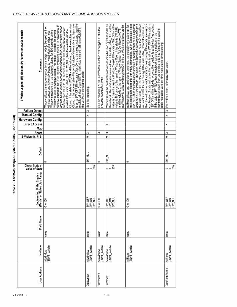
EXCEL 10 W7750A,B,C CONSTANT VOLUME AHU CONTROLLER
74-2958�2 104
nviW
indow
(S
NVT_
switc
h)va
lue0 t
o 100
0W
indow
allow
s the
wind
ow se
nsor
from
anoth
er no
de to
be us
ed as
the
wind
ow se
nsor
and i
s typ
ically
boun
d to n
voW
indow
of an
other
node
. W
indow
mus
t sho
w tha
t the w
indow
is cl
osed
for 3
00 se
cond
s befo
re
Wind
ow is
used
as w
indow
clos
ed. T
his m
akes
it po
ssibl
e for
seve
ral
wind
ow se
nsor
s to b
e ORe
d tog
ether
by bi
nding
them
all to
nviW
indow
. If
any o
ne bo
und w
indow
sens
or sh
ows w
indow
open
, then
Wind
ow sh
ows
wind
ow op
en fo
r up t
o 300
seco
nds a
fter t
he la
st se
nsor
show
s wind
ow
close
d. If t
he st
ate is
SW
_OFF
or S
W_N
UL, th
en th
e res
ult is
Wind
ow
Clos
ed. If
the s
tate i
s SW
_ON
and t
he va
lue is
0, th
en th
e res
ult is
Wind
ow
Clos
ed. If
the n
ode r
eceiv
es th
is co
mbina
tion o
f stat
e and
value
, then
state
is
set to
SW
_OFF
. If th
e stat
e is S
W_O
N an
d the
value
is no
t zer
o, the
n the
re
sult i
s Wind
ow O
pen.
NOTE
: nviW
indow
is ca
lled n
viEne
rgyH
oldOf
f in
the L O
NMAR
K com
plian
ce pr
ofile.
DestW
ndw
nviW
indow
(S
NVT_
switc
h)sta
teSW
_OFF
SW_O
NSW
_NUL
0 1 255
SW_N
ULM
XX
XX
See t
he pr
eced
ing.
SrcW
ndwC
tnv
oWind
ow
(SNV
T_sw
itch)
value
0 to 1
000
XSe
e the
prec
eding
.NOT
E: nv
oWind
ow is
calle
d nviE
nerg
yHold
Off in
the
LonM
ark c
ompli
ance
profi
le.Sr
cWnd
wnv
oWind
ow
(SNV
T_sw
itch)
state
SW_O
FFSW
_ON
SW_N
UL
0 1 255
SW_N
ULM
XX
Wind
ow al
lows t
he ha
rd w
ired w
indow
sens
or to
be us
ed by
othe
r nod
es on
the
netw
ork.
The v
alid s
tates
are a
s foll
ows:
If the
state
is S
W_O
FF an
d the
va
lue is
0 the
n the
resu
lt is W
indow
Clos
ed. If
the s
tate i
s SW
_ON
and t
he
value
is 10
0 per
cent,
the r
esult
is W
indow
Ope
n. If t
he st
ate is
SW
_NUL
an
d the
value
is 0,
the r
esult
is W
indow
Sen
sor N
ot Co
nfigu
red.
NOTE
: nv
oWind
ow is
calle
d nviE
nerg
yHold
Off in
the L
onMa
rk co
mplia
nce p
rofile
.nv
iEco
n(S
NVT_
switc
h)va
lue0 t
o 100
0nv
iEco
n allo
ws on
e con
trolle
r to d
eterm
ine th
e suit
abilit
y of o
utdoo
r air f
or
free c
oolin
g and
shar
e this
with
man
y othe
r nod
es. W
hen E
con.s
tate i
s not
SW_N
UL, th
en th
e loc
al se
nsor
selec
ted by
Con
fig.E
conE
nable
is ig
nore
d an
d Eco
n is u
sed i
nstea
d. Th
e inp
uts st
ates h
ave t
he fo
llowi
ng m
eanin
gs: If
the
state
is S
W_O
FF or
othe
r and
the v
alue i
s don
�t car
e, the
n the
outdo
or
air is
not s
uitab
le for
free
cooli
ng. If
the s
tate i
s SW
_ON
and t
he va
lue is
0,
then t
he ou
tdoor
air is
not s
uitab
le for
free
cooli
ng. If
the n
ode r
eceiv
es th
is co
mbina
tion o
f stat
e and
value
, then
state
is se
t to S
W_O
FF. If
the s
tate i
s SW
_ON
and t
he va
lue is
not z
ero,
then o
utdoo
r is su
itable
for f
ree c
oolin
g. If t
he st
ate is
SW
_NUL
, then
the n
etwor
k var
iable
is no
t bou
nd, th
e co
mmun
icatio
ns pa
th fro
m the
send
ing no
de ha
s fail
ed, o
r the
send
ing
node
has f
ailed
. Outd
oor a
ir is n
ot su
itable
for f
ree c
oolin
g.De
stEco
nEna
blenv
iEco
n(S
NVT_
switc
h)sta
teSW
_OFF
SW_O
NSW
_NUL
0 1 255
SW_N
ULM
XX
XX
For n
viEco
n.stat
e, re
fer to
nviE
con.v
alue.
Tabl
e 26
. LO
NM
AR
K®
/Ope
n Sy
stem
Poi
nts.
(Con
tinue
d)
User
Add
ress
NvNa
me
Field
Nam
eEn
gine
erin
g Un
its: E
nglis
h (M
etric
) or S
tate
s plu
s Ran
ge
Digital State or Value of State
Defa
ult
E-Vision (M, P, S)Share
Map Direct Access
Hardware Config.Manual Config.Failure Detect
E-Vi
sion
Lege
nd: (
M) M
onito
r, (P
) Par
amet
er, (
S) S
chem
atic
Com
men
ts

EXCEL 10 W7750A,B,C CONSTANT VOLUME AHU CONTROLLER
105 74-2958�2
SrcE
conE
nCt
nvoE
con
(SNV
T_sw
itch)
value
0 to 1
000
Xnv
oEco
n allo
ws on
e con
trolle
r to d
eterm
ine th
e suit
abilit
y of o
utdoo
r air f
or
free c
oolin
g and
shar
e this
with
othe
r nod
es an
d is t
ypica
lly bo
und t
o Eco
n on
othe
r nod
es. If
the e
cono
mize
r fun
ction
is co
nfigu
red b
y Co
nfig.E
conE
nable
, Eco
n is p
eriod
ically
calcu
lated
from
the l
ocal
sens
or
spec
ified b
y Con
fig.E
conE
nable
and i
s sen
t on t
he ne
twor
k. Ec
on do
es no
t aff
ect E
con.
The o
utput
has t
he fo
llowi
ng st
ates:
If the
state
is S
W_O
FF
and t
he va
lue is
0, th
en th
e outd
oor a
ir is n
ot su
itable
for f
ree c
oolin
g. If t
he
state
is SW
_ON
and t
he va
lue is
100 p
erce
nt, th
en th
e outd
oor a
ir is
suita
ble fo
r fre
e coo
ling.
If the
state
is S
W_N
UL an
d the
value
is 0,
the
corre
spon
ding e
cono
mize
r fun
ction
is no
t ena
bled b
ecau
se
Confi
g.Eco
nEna
ble is
ECO
N_NU
L, DI
FF_T
EMP,
or D
IFF_
ENTH
or
beca
use t
he se
lected
sens
or ha
s fail
ed.
SrcE
conE
nable
nvoE
con
(SNV
T_sw
itch)
state
SW_O
FFSW
_ON
SW_N
UL
0 1 255
SW_N
ULM
XX
For n
voEc
on.st
ate, r
efer t
o nvo
Econ
.value
.
Tabl
e 26
. LO
NM
AR
K®
/Ope
n Sy
stem
Poi
nts.
(Con
tinue
d)
User
Add
ress
NvNa
me
Field
Nam
eEn
gine
erin
g Un
its: E
nglis
h (M
etric
) or S
tate
s plu
s Ran
ge
Digital State or Value of State
Defa
ult
E-Vision (M, P, S)Share
Map Direct Access
Hardware Config.Manual Config.Failure Detect
E-Vi
sion
Lege
nd: (
M) M
onito
r, (P
) Par
amet
er, (
S) S
chem
atic
Com
men
ts
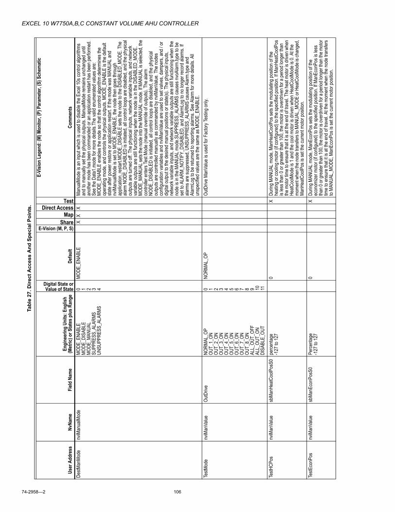
EXCEL 10 W7750A,B,C CONSTANT VOLUME AHU CONTROLLER
74-2958�2 106
Tabl
e 27
. Dire
ct A
cces
s A
nd S
peci
al P
oint
s.
User
Add
ress
NvNa
me
Field
Nam
eEn
gine
erin
g Un
its: E
nglis
h (M
etric
) or S
tate
s plu
s Ran
ge
Digital State or Value of State
Defa
ult
E-Vision (M, P, S)Share
Map Direct Access
Test
E-Vi
sion
Lege
nd: (
M) M
onito
r, (P
) Par
amet
er, (
S) S
chem
atic
Com
men
tsDe
stMan
Mode
nviM
anua
lMod
eMO
DE_E
NABL
EMO
DE_D
ISAB
LEMO
DE_M
ANUA
LSU
PPRE
SS_A
LARM
SUN
SUPP
RESS
_ALA
RMS
0 1 2 3 4
MODE
_ENA
BLE
XX
XMa
nualM
ode i
s an i
nput
which
is us
ed to
disa
ble th
e Exc
el 10
s con
trol a
lgorith
ms
and t
o man
ually
set th
e phy
sical
outpu
ts. M
anua
lMod
e rem
ains u
ncha
nged
until
anoth
er m
ode h
as be
en co
mman
ded o
r an a
pplic
ation
resta
rt ha
s bee
n per
forme
d. Se
e the
Data
1.mod
e for
mor
e deta
ils.T
he va
lid en
umer
ated v
alues
are:
MODE
_ENA
BLE
enab
les th
e nod
e so t
hat th
e con
trol a
lgorith
m de
termi
nes t
he
oper
ating
mod
e, an
d con
trols
the ph
ysica
l outp
uts. M
ODE_
ENAB
LE is
the d
efault
sta
te aft
er po
wer r
estor
e or a
pplic
ation
resta
rt. If
the m
ode w
as M
ANUA
L and
nv
iMan
ualM
ode i
s set
to MO
DE_E
NABL
E, th
e nod
e the
n goe
s thr
ough
ap
plica
tion_
resta
rt.MO
DE_D
ISAB
LE se
ts the
node
to th
e DIS
ABLE
D_MO
DE. T
he
alarm
NOD
E_DI
SABL
ED is
initia
ted, a
ll con
trol lo
ops a
re di
sable
d, an
d the
phys
ical
outpu
ts ar
e tur
ned o
ff. Th
e phy
sical
inputs
, netw
ork v
ariab
le inp
uts, a
nd ne
twor
k va
riable
outpu
ts ar
e still
func
tionin
g whe
n the
node
is in
the D
ISAB
LED_
MODE
. MO
DE_M
ANUA
L sets
the n
ode i
nto th
e MAN
UAL m
ode.
If MAN
UAL i
s sele
cted,
the
contr
oller
enter
s Tes
t Mod
e (ma
nual
over
ride o
f outp
uts).
The a
larm
NODE
_DIS
ABLE
D is
initia
ted, a
ll con
trol lo
ops a
re di
sable
d, an
d the
phys
ical
outpu
ts ar
e con
trolle
d man
ually
as co
mman
ded b
y nviM
anVa
lue. T
he no
des
confi
gura
tion v
ariab
les an
d nviM
anVa
lue ar
e use
d to s
et va
lves,
damp
ers,
and /
or
digita
l outp
ut to
the de
sired
man
ual p
ositio
ns or
state
(s). T
he ph
ysica
l inpu
ts,
netw
ork v
ariab
le inp
uts, a
nd ne
twor
k var
iable
outpu
ts ar
e still
func
tionin
g whe
n the
no
de is
in th
e MAN
UAL m
ode.S
UPPR
ESS_
ALAR
MS ca
uses
nvoA
larm.
type t
o be
set to
ALA
RM_N
OTIF
Y_DI
SABL
ED, a
nd A
larmL
og to
no lo
nger
reco
rd al
arms
. If
alarm
s are
supp
ress
ed, U
NSUP
PRES
S_AL
ARMS
caus
es A
larm.
type a
nd
Alar
mLog
to be
retur
ned t
o rep
ortin
g alar
ms. S
ee A
larm
for m
ore d
etails
. All
unsp
ecifie
d valu
es ar
e the
same
as M
ODE_
ENAB
LE.
TestM
ode
nviM
anVa
lueOu
tDriv
eNO
RMAL
_OP
OUT_
1_ON
OUT_
2_ON
OUT_
3_ON
OUT_
4_ON
OUT_
5_ON
OUT_
6_ON
OUT_
7_ON
OUT_
8_ON
ALL_
OUT_
OFF
ALL_
OUT_
ONDI
SABL
E_OU
T
0 1 2 3 4 5 6 7 8 9 10 11
NORM
AL_O
POu
tDriv
e Man
Value
is us
ed fo
r Fac
tory T
estin
g only
.
TestH
CPos
nviM
anVa
luesb
ManH
eatC
oolP
osS0
perce
ntage
-127
to 12
70
XDu
ring M
ANUA
L mod
e, Ma
nHea
tCoo
lPos
sets
the m
odula
ting p
ositio
n of th
e he
ating
or co
oling
moto
r (if c
onfig
ured
) to t
he sp
ecifie
d pos
ition.
If Man
HeatC
oolP
os
is les
s tha
n 0 or
grea
ter th
an 10
0, the
moto
r is ov
erdr
iven f
or a
perio
d lon
ger t
han
the m
otor t
ime t
o ens
ure t
hat it
is at
the e
nd of
trav
el. T
he he
at mo
tor is
drive
n whe
n He
atCoo
lMod
e is 1
and t
he co
ol mo
tor is
drive
n whe
n Hea
tCoo
lMod
e is 0
. At th
e mo
ment
when
the n
ode t
rans
fers t
o MAN
UAL_
MODE
or H
eatC
oolM
ode i
s cha
nged
, Ma
nHea
tCoo
lPos
is se
t the c
urre
nt mo
tor po
sition
.Te
stEco
nPos
nviM
anVa
luesb
ManE
conP
osS0
Perce
ntage
-127
to 12
70
XDu
ring M
ANUA
L mod
e, Ma
nEco
nPos
sets
the m
odula
ting p
ositio
n of th
e ec
onom
izer m
otor (
if con
figur
ed) t
o the
spec
ified p
ositio
n. If M
anEc
onPo
s is l
ess
than 0
or gr
eater
than
100,
the m
otor is
over
drive
n for
a pe
riod l
onge
r tha
n the
moto
r tim
e to e
nsur
e tha
t it is
at th
e end
of tr
avel.
At th
e mom
ent w
hen t
he no
de tr
ansfe
rs to
MANU
AL_M
ODE,
Man
Econ
Pos i
s set
the cu
rrent
motor
posit
ion.

EXCEL 10 W7750A,B,C CONSTANT VOLUME AHU CONTROLLER
107 74-2958�2
TestH
tClS
tg1nv
iMan
Value
HeatC
oolS
tage1
OFF
ON0 1
OFF
X
Durin
g MAN
UAL m
ode,
HeatC
oolS
tage1
para
meter
s tur
n the
corre
spon
ding h
eat,
or co
ol sta
ge to
on (1
) or o
ff (0)
. Whe
n Hea
tCoo
lMod
e is 0
, then
cooli
ng lo
ads a
re
contr
olled
. Whe
n Hea
tCoo
lMod
e is 1
and t
he no
de is
contr
olling
conv
entio
nal
equip
ment,
then
heati
ng lo
ads a
re co
ntroll
ed. W
hen H
eatC
oolM
ode i
s 1 an
d the
no
de is
contr
olling
a he
at pu
mp, th
en co
oling
load
s are
contr
olled
.Te
stHtC
lStg2
nviM
anVa
lueHe
atCoo
lStag
e2OF
FON
0 1OF
FX
For H
eatC
oolS
tage2
, refe
r to H
eatC
oolS
tage1
.
TestH
tClS
tg3nv
iMan
Value
HeatC
oolS
tage3
OFF
ON0 1
OFF
XFo
r Hea
tCoo
lStag
e3, r
efer t
o Hea
tCoo
lStag
e1.
TestH
tClS
tg4nv
iMan
Value
HeatC
oolS
tage4
OFF
ON0 1
OFF
XFo
r Hea
tCoo
lStag
e4. r
efer t
o Hea
tCoo
lStag
e1.
TestA
uxHt
1nv
iMan
Value
AuxH
eatC
oolS
tage1
OFF
ON0 1
OFF
XAu
xHea
tCoo
lStag
e1�
Durin
g MAN
UAL m
ode w
hen t
he no
de is
confi
gure
d to
contr
ol a h
eat p
ump a
nd H
eatC
oolM
ode i
s 1, th
ese p
aram
eters
turn t
he
corre
spon
ding a
uxilia
ry he
at sta
ge on
(1) o
r off (
0).
TestA
uxHt
2nv
iMan
Value
AuxH
eatC
oolS
tage2
OFF
ON0 1
OFF
XAu
xHea
tCoo
lStag
e2�
Durin
g MAN
UAL m
ode w
hen t
he no
de is
confi
gure
d to
contr
ol a h
eat p
ump a
nd H
eatC
oolM
ode i
s 1, th
ese p
aram
eters
turn t
he
corre
spon
ding a
uxilia
ry he
at sta
ge on
(1) o
r off (
0).
TestA
uxHt
3nv
iMan
Value
AuxH
eatC
oolS
tage3
OFF
ON0 1
OFF
XAu
xHea
tCoo
lStag
e3�
Durin
g MAN
UAL m
ode w
hen t
he no
de is
confi
gure
d to
contr
ol a h
eat p
ump a
nd H
eatC
oolM
ode i
s 1, th
ese p
aram
eters
turn t
he
corre
spon
ding a
uxilia
ry he
at sta
ge on
(1) o
r off (
0).
TestA
uxHt
4nv
iMan
Value
AuxH
eatC
oolS
tage4
OFF
ON0 1
OFF
XAu
xHea
tCoo
lStag
e4�
Durin
g MAN
UAL m
ode w
hen t
he no
de is
confi
gure
d to
contr
ol a h
eat p
ump a
nd H
eatC
oolM
ode i
s 1, th
ese p
aram
eters
turn t
he
corre
spon
ding a
uxilia
ry he
at sta
ge on
(1) o
r off (
0).
TestH
tClM
ode
nviM
anVa
lueHe
atCoo
lMod
eOF
FON
0 1OF
FX
Durin
g MAN
UAL m
ode,
HeatC
oolM
ode d
eterm
ines w
hethe
r hea
ting o
r coo
ling
outpu
ts ar
e tur
ned o
n or o
ff man
ually
. Whe
n Hea
tCoo
lMod
e is 0
, then
cooli
ng lo
ads
are c
ontro
lled.
Whe
n Hea
tCoo
lMod
e is 1
and t
he no
de is
contr
olling
conv
entio
nal
equip
ment,
then
heati
ng lo
ads a
re co
ntroll
ed. W
hen H
eatC
oolM
ode i
s 1 an
d the
no
de is
contr
olling
a he
at pu
mp, th
en co
oling
load
s are
contr
olled
by H
eat /
Cool
stage
s and
heati
ng st
ages
are c
ontro
lled b
y aux
iliary
heat
stage
s. Th
e CH
ANGE
_OVE
R_RE
LAY_
OUT
is aff
ected
by H
eatC
oolM
ode a
s con
figur
ed in
Se
lect.
TestS
aFan
nviM
anVa
lueFa
nOut
OFF
ON0 1
OFF
XDu
ring M
ANUA
L mod
e, Fa
nOut
turns
the f
an on
(1) o
r off (
0).
TestA
uxEc
onnv
iMan
Value
AuxE
conO
utOF
FON
0 1OF
FX
Durin
g MAN
UAL m
ode,
AuxE
conO
ut tur
ns th
e AUX
_ECO
N_OU
T on
(1) o
r off(
0).
TestO
ccSt
atnv
iMan
Value
OccS
tatus
Out
OFF
ON0 1
OFF
XDu
ring M
ANUA
L mod
e, Oc
cStat
usOu
t turn
s the
OCC
UPAN
CY_S
TATU
S_OU
T to
on(1
= no
t OC_
UNOC
CUPI
ED) o
r off (
0).
TestF
ree1
nviM
anVa
lueFr
ee1O
utOF
FON
0 1OF
FX
Durin
g MAN
UAL m
ode,
Free
1Out
turns
the F
REE1
_OUT
on(1
) or o
ff(0)
.
TestF
ree2
nviM
anVa
lueFr
ee2O
utOF
FON
0 1OF
FX
Durin
g MAN
UAL m
ode,
Free
2Out
turns
the F
REE2
_OUT
on(1
) or o
ff(0)
.
Tabl
e 27
. Dire
ct A
cces
s A
nd S
peci
al P
oint
s. (C
ontin
ued)
User
Add
ress
NvNa
me
Field
Nam
eEn
gine
erin
g Un
its: E
nglis
h (M
etric
) or S
tate
s plu
s Ran
ge
Digital State or Value of State
Defa
ult
E-Vision (M, P, S)Share
Map Direct Access
Test
E-Vi
sion
Lege
nd: (
M) M
onito
r, (P
) Par
amet
er, (
S) S
chem
atic
Com
men
ts

EXCEL 10 W7750A,B,C CONSTANT VOLUME AHU CONTROLLER
74-2958�2 108
Tabl
e 28
. Dat
a Sh
are
Poin
ts.
User
Add
ress
NvNa
me
Field
Nam
eEn
gine
erin
g Un
its: E
nglis
h (M
etric
) or S
tate
s plu
s Ran
ge
Digital State or Value of State
Defa
ult
E-Vision (M, P, S)Share
Map Direct AccessManual Config.Failure Detect
E-Vi
sion
Lege
nd: (
M) M
onito
r, (P
) Par
amet
er, (
S) S
chem
atic
Com
men
tsDe
stOaE
nthnv
iOdE
nthS7
mA 4 to 2
0SI
_INVA
LIDX
XX
nviO
dEnth
allow
s one
outdo
or en
thalpy
sens
or at
a no
de to
be sh
ared
by m
any
other
node
s. W
hen n
viOdE
nth is
not S
I_INV
ALID
then
any l
ocal
sens
or is
ign
ored
by th
e loc
al co
ntrol
algor
ithm
and O
dEnth
is us
ed in
stead
. If th
e valu
e is
outsi
de th
e allo
wed r
ange
(4 to
20 m
A), th
en th
e nod
e use
s the
value
of th
e ne
ares
t ran
ge lim
it.Sr
cOaE
nthnv
oOdE
nthS7
mA 4 to 2
0SI
_INVA
LIDM
XX
nvoO
dEnth
allow
s the
loca
l outd
oor e
nthalp
y sen
sor t
o be s
hare
d with
othe
r no
des a
nd is
typic
ally b
ound
to O
dEnth
on ot
her n
odes
. If th
e loc
al se
nsor
is
confi
gure
d by S
elect,
nviO
dEnth
is pe
riodic
ally s
ent o
n the
netw
ork.
If the
loca
l se
nsor
is no
t con
figur
ed or
curre
ntly s
howi
ng an
erro
r, the
value
is S
I_INV
ALID
.Sr
cMon
SwCt
nvoM
onSw
value
0 to 1
000
XMo
nSw
value
allow
s the
mon
itor s
witch
to be
shar
ed w
ith an
other
node
. Mon
Sw
is typ
ically
boun
d to a
n SBC
to in
dicate
a us
er de
fined
alar
m co
nditio
n. Th
e ou
tput v
alues
have
the f
ollow
ing m
eanin
gs: If
the s
tate i
s SW
_OFF
and t
he
value
is 0,
then
the m
onito
r swi
tch is
open
. If th
e stat
e is S
W_O
N an
d the
value
is
100 p
erce
nt, th
en th
e mon
itor s
witch
is cl
osed
. If th
e stat
e is S
W_N
UL an
d the
value
is 0,
then
the m
onito
r swi
tch is
not c
onfig
ured
by S
elect.
SrcM
onSw
nvoM
onSw
state
SW_O
FFSW
_ON
SW_N
UL
0 1 255
SW_N
ULM
XFo
r Mon
Sw.st
ate, r
efer t
o Mon
Sw.va
lue.
nviIa
qOvr
value
0 to 1
000
IaqOv
r allo
ws an
indo
or ai
r qua
lity se
nsor
to be
shar
ed by
man
y othe
r nod
es.
The s
tates
are f
ollow
s: If t
he st
ate is
SW
_OFF
and t
he va
lue is
don�t
care
, then
the
indo
or ai
r qua
lity is
acce
ptable
. If th
e stat
e is S
W_O
N an
d the
value
is 0,
the
n the
indo
or ai
r qua
lity is
acce
ptable
. If th
e nod
e rec
eives
this
comb
inatio
n of
state
and v
alue,
then s
tate i
s set
to SW
_OFF
. If th
e stat
e is S
W_O
N an
d the
va
lue is
not z
ero,
then t
he in
door
air q
uality
is no
t acc
eptab
le an
d add
itiona
l ou
tdoor
air is
need
ed to
bring
it ba
ck to
acce
ptable
. If th
e stat
e is S
W_N
UL an
d the
value
is do
n�t ca
re, th
en th
e ind
oor a
ir qua
lity is
acce
ptable
. If th
e stat
e is
other,
then
the n
etwor
k var
iable
is no
t bou
nd, th
e com
munic
ation
s path
from
the
send
ing no
de ha
s fail
ed, o
r the
send
ing no
de ha
s fail
ed. T
he in
door
air q
uality
is
acce
ptable
.De
stIaq
Ovrd
nviIa
qOvr
state
SW_O
FFSW
_ON
SW_N
UL
0 1 255
SW_N
ULM
XX
XX
For I
aqOv
r.stat
e, re
fer to
IaqO
vr.va
lue.
SrcIa
qOvrC
tnv
oIaqO
vrva
lue0 t
o 100
0X
XIaq
Ovr a
llows
an in
door
air q
uality
sens
or to
be sh
ared
with
othe
r nod
es an
d is
typica
lly bo
und t
o Iaq
Ovr o
n othe
r nod
es. If
Data
2.siS
pace
Co2 i
s not
SI_IN
VALID
, and
exce
eds A
ux1S
etPt.C
O2Iaq
Limit,
then p
oor a
ir qua
lity is
de
tected
. In ad
dition
, if a
local
digita
l inpu
t is co
nfigu
red f
or IA
Q_OV
ERRI
DE_IN
an
d IO.
IaqOv
erRi
de is
1 (T
RUE)
then
poor
air q
uality
is al
so de
tected
. The
state
ha
s the
follo
wing
mea
nings
: If th
e stat
e is S
W_O
FF an
d the
value
is 0,
then
the
indoo
r air q
uality
is ac
cepta
ble. If
the s
tate i
s SW
_ON
and t
he va
lue is
100
perce
nt, th
en th
e ind
oor a
ir qua
lity is
not a
ccep
table
and a
dditio
nal o
utdoo
r air i
s ne
eded
to br
ing it
back
to an
acce
ptable
state
. If th
e stat
e is S
W_N
UL an
d the
va
lue is
0, th
en th
e eco
nomi
zer f
or th
is no
de ha
s not
been
confi
gure
d or t
here
is
no se
nsor
(via
IO.S
pace
Do2 o
r IO.
IaqOv
erRi
de) c
onfig
ured
or th
e only
co
nfigu
red s
enso
r (via
IO.S
pace
Co2)
has f
ailed
.Sr
cIaqO
vrnv
oIaqO
vrsta
teSW
_OFF
SW_O
NSW
_NUL
0 1 255
SW_N
ULM
XX
For I
aqOv
r.Stat
e, re
fer to
IaqO
vr.va
lue.

EXCEL 10 W7750A,B,C CONSTANT VOLUME AHU CONTROLLER
109 74-2958�2
Appendix D: XL5000 Q7750A Excel 10 Zone Manager Point Estimating GuideMemory size approximation shown below (all sizes in bytes):
When memory size is less than 110,000 bytes, the size is OK.
When memory size is between 110,000 and 128,000 bytes, the application may be too large. The user must expect to reduce the application complexity, reduce the number of attached Excel 10s or distribute the Excel 10s over more than one Zone Manager.
When memory size is greater than 128,000, the size is too large. The application size must be reduced as described above.
Approximate Memory Size Estimating Procedure.1. Determine the number of points per controller required
at the Central (for example, XBS).
NOTE: All remaining points that are not mapped can be accessed through the Direct Access feature.
2. Calculate the number of Excel 10 Zone Manager pro-gram points that are used in control logic and in the switching table.
3. Estimate the program complexity of the Zone Manager (one of three levels).a. No time programs, control logic, or switching tables.b. 10K of control logic (one time program, five
switching tables, and five control loops).c. 20K of control logic (multiple time programs, ten
switching tables, and ten control loops).Use Fig. 51 to determine the number of Excel 10s that can be connected to the Zone Manager.NOTE: More than 60 Excel 10s requires a Router.
4. Repeat for each Q7750A Excel 10 Zone Manager in a project.
Fig. 51. Point capacity estimate for Zone Manager.
The exact equation for calculating memory size follows:Memory size = 21,780+ 4096 (in case of a time program).+ CARE Control Program.+ 14 x time points x Excel 10 units.+ 50 x Excel 10 units.+ map complexity x Excel 10 units x mapped points.+ 57 x C-Bus points.+ 7488 x Excel 10 types.
Where:Time points = number of switch points in time program
per Excel 10.
Excel 10 units =number of attached Excel 10s.C-Bus points = including mapped points and others; for
example, remote points.Mapped points = number of mapped points per Excel 10,
including One-to-Many and Many-to-One mechanism.
Excel 10 types = number of different Excel 10 types (currently three)
Map complexity=20 =using One-to-Many and not using points
with read/write.30 = average.45 = many points with read/write ability.
20 60 120
600
700
800
900
600
700
800
900
920
765
610
585
740
895
NUMBER OFC-BUS POINTS(EXCEL 10MAPPED POINTSPLUS ZONEMANAGERPOINTS)
(OR LESS) (ADD ROUTER)
NUMBER OF EXCEL 10s
(C)
(A)
NUMBER OFC-BUS POINTS(EXCEL 10MAPPED POINTSPLUS ZONEMANAGERPOINTS)
NO TIME PROGRAM,NO CONTROL LOOPS, NO SWITCHING TABLES.
20K CONTROL PROGRAM(I.E., MULTIPLE TIME PROGRAMS,10 CONTROL LOOPS, 10 SWITCHING TABLES.)
10K CONTROL PROGRAM(FOR EXAMPLE, 1 TIME PROGRAM,5 CONTROL LOOPS, 5 SWITCHING TABLES.)
(B)
M8729

EXCEL 10 W7750A,B,C CONSTANT VOLUME AHU CONTROLLER
74-2958�2 110
Appendix E: Sensor Data for Calibration
Resistance Sensors
Sensor Type: C7100A, C7170A. (PT3000)
Sensor Use: Discharge air, Outdoor air.
Table 29 lists the points for sensor resistance versus temperature. Fig. 52 shows the graph of these points.
Table 29. PT3000 Sensor Resistance Versus Temperature.
Fig. 52. PT3000 Sensor resistance versus temperature.
Sensor Type: C7041B,C,D,F,J,K (W7750B,C only).
Sensor Use: Return Air, Discharge Air Temperature (20K ohm).
Fig. 53 shows the graph of 20K ohm sensor resistance versus temperature.
Sensor Type: T7770A,B,C,D; T7560A,B and C7770A. (20K ohm)
Sensor Use:Space Temperature and Discharge/Return Air Temperature.
Fig. 53 shows the graph of sensor resistance versus temperature.
Fig. 53. 20K ohm sensor resistance versus temperature.
Sensor Type:T7770B,C 10K ohm linear setpoint potentiometer (Relative).
Sensor Use: Setpoint Offset Temperature.
Sensor Resistance versus Temperature Difference (above and below the setpoint):Offset -9°F: 9574 ohms.Setpoint: 5500 ohms.Offset +9°F: 1426 ohms.
Sensor Type:T7770B,C 10K ohm setpoint potentiometer (Absolute).
Sensor Use: Direct Setpoint Temperature.
Sensor Resistance versus Temperature:55°F (13°C): 9574 ohms.70°F (21°C): 5500 ohms.85°F (29°C): 1426 ohms.
°F Resistance Ohms-40 2916.08-30 2964.68-20 3013.28-10 3061.880 3110.48
10 3159.0820 3207.6830 3256.2840 3304.8850 3353.4860 3402.0870 3450.6880 3499.2890 3547.88100 3596.48110 3645.08120 3693.68
30503000
29502900
3100
3150
3200325033003350
340034503500
3550
3600
365037003750
50403020100-10-20-30-40 60 70 80 90 100 110 120
OH
MS
DEGREES F
SENSOR RESISTANCE VERSUS TEMPERATURE
M11615
TEMPERATURE (DEGREES)
oF30 40 50 60 70 80 90 100 110
0 10 20 30 40
RE
SIS
TA
NC
E (
OH
MS
)
20K OHM AT 77oF (25oC)
80K
70K
60K
50K
40K
30K
20K
10K
oC
M5874A

EXCEL 10 W7750A,B,C CONSTANT VOLUME AHU CONTROLLER
111 74-2958�2
Voltage/Current Sensors
Sensor Type: C7600B 2 to 10V.
Sensor Use: Humidity.
Table 30 lists the points for sensor voltage versus humidity. Fig. 54 shows the graph of these points.
Table 30. C7600B Sensor Voltage Versus Humidity.
Fig. 54. C7600B Sensor voltage versus humidity.
Sensor Type: C7600C (4 to 20 mA).
Sensor Use: Humidity.
Table 31 lists the points for sensor voltage versus humidity. Fig. 55 shows the graph of these points.
Table 31. C7600C Sensor Current Versus Humidity.
Fig. 55. C7600C output current versus humidity.
Humidity Percentage Sensor Voltage10 2.6715 3.0820 3.4825 3.8830 4.2835 4.6840 5.0845 5.4850 5.8855 6.2860 6.6965 7.0970 7.4975 7.8980 8.2985 8.6990 9.09
2.50
3.00
3.50
4.00
4.50
5.00
5.50
6.00
6.50
7.00
7.50
8.00
8.50
9.00
9.50
10.00
10 15 20 25 30 35 40 45 50 55 60 65 70 75 80 85 90
VO
LT
S
PERCENTAGE
SENSOR VOLTAGE VERSUS HUMIDITY PERCENTAGE
M11610
Relative Humidity Percentage Sensor Current10 5.620 7.230 8.840 10.450 12.060 13.670 15.280 16.890 18.4
HUMIDITY IN % RH
CU
RR
ENT
IN m
A
4
18
8
16
6
14
12
20
10
10M3131B
5.67.28.8
10.412.013.615.216.8 18.4
102030405060708090
20 10090807060504030
RH (%) I (mA)
0

EXCEL 10 W7750A,B,C CONSTANT VOLUME AHU CONTROLLER
74-2958�2 112
Sensor Type: C7400A.
Sensor Use: Enthalpy.
Table 32 lists the points for sensor current versus enthalpy (volts). Fig. 56 shows the graph of these points.
Table 32. C7400A Sensor Current Versus Enthalpy (volts).
Fig. 56. C7400A Sensor current versus enthalpy (volts).
See Fig. 57 for partial psychrometric chart for a C7400A Solid State Enthalpy Sensor.
See Fig. 58 for a C7400A Solid State Enthalpy Sensor output current vs. relative humidity.
Sensor Current (mA) Enthalpy (Volts)4 15 1.256 1.497 1.748 1.999 2.2410 2.4911 2.7412 2.9913 3.2414 3.4915 3.7416 3.9817 4.2318 4.4819 4.7320 4.98
1.00
1.25
1.50
1.75
2.00
2.25
2.50
2.75
3.00
3.25
3.50
3.75
4.00
4.25
4.50
4.75
5.00
4 5 6 7 8 9 10 11 12 13 14 15 16 17 18 19 20
EN
TH
AL
PY
(V
OL
TS
)
(MA)
SENSOR CURRENT VERSUS ENTHALPY (VOLTS)
M11607

EXCEL 10 W7750A,B,C CONSTANT VOLUME AHU CONTROLLER
113 74-2958�2
Fig. 57. Partial psychrometric chart for a C7400A Solid State Enthalpy Sensor.
Fig. 58. C7400A Solid State Enthalpy Sensor output current versus relative humidity.
CONTROLCURVE
A
B
C
D
CONTROL POINTAPPROX. F ( C)
AT 50% RH
73 (23)
70 (21)
67 (19)
63 (17)12
14
16
18
20
22
24
26
28
30
32
34
36
38
40
42
44
46
90100
80
70
60
50
40
30
20
10
EN
TH
ALPY—
BTU
PER
PO
UN
D D
RY A
IR
85(29)
90(32)
95(35)
100(38)
105(41)
110(43)
35(2)
35(2)
40(4)
40(4)
105(41)
110(43)
45(7)
45(7)
50(10)
50(10)
55(13)
55(13)
60(16)
60(16)
65(18)
65(18)
70(21)
70(21)
75(24)
75(24)
80(27)
80(27)
85(29)
90(32)
95(35)
100(38)
APPROXIMATE DRY BULB TEMPERATURE— F ( C)
A
A
B
B
C
C
D
D
M11806
RE
LA
TIV
E H
UM
IDIT
Y (%
)
20
10
30
40
50
60
70
80
90
100
605040 70 80 90 100
PE
RC
EN
T R
H
TEMPERATURE F ( C) M11605
C7400A OUTPUT CURRENT
4 m
A
6 m
A
8 m
A
10 m
A
20 m
A18 m
A16 m
A14 m
A12 m
A
(4) (10) (16) (21) (27) (32) (38)
D C B A
D = 17 MAC = 15.5 MAB = 13.5 MAA = 11 MA

EXCEL 10 W7750A,B,C CONSTANT VOLUME AHU CONTROLLER
74-2958�2 114
Sensor Type: C7232 or C7632.
Sensor Use: CO2 concentration.
Table 33 lists the points for sensor voltage versus CO2 concentration. Fig. 59 shows the graph of these points.
Table 33. C7232, C7632 Voltage Versus CO2 Concentration.
Fig. 59. C7232, C7632 voltage versus CO2 concentration.
Sensor Type: P7640A,B (4-20 mA with 500 ohm resistor to convert to 2-10 Vdc).
Sensor Use: Sensor voltage (Vdc) /pressure (in. w.c.) 2 to 10 Vdc, 0 to 5 in. w.c. (1.25 kPa).
Table 34 lists the points for sensor voltage (Vdc) versus pressure (in. w.c.). Fig. 60 shows the graph of these points.
Table 34. P7640 Voltage (Vdc) Versus Pressure (in. w.c.).
Fig. 60. P7640 voltage (Vdc) versus pressure (in. w.c.).
Sensor Type: Third party (2 to 10V).
Sensor Use: Monitor voltage.
CO2 Concentration PPM Sensor Voltage0 0.00
100 0.50200 1.00300 1.50400 2.00500 2.50600 3.00700 3.50800 4.00900 4.501000 5.001100 5.501200 6.001300 6.501400 7.001500 7.501600 8.001700 8.501800 9.001900 9.502000 10.00
0
1
2
3
4
5
6
7
8
9
10
100 300 500 700 900 1100 1300 1500 1700 1900200 400 600 800 1000 1200 1400 1600 1800 2000
VO
LT
S
PPM
SENSOR VOLTAGE VERSUS CO2 CONCENTRATION
M11611
Pressure in. w.c. (kPa) Sensor Voltage (Vdc)0.00 (0.00) 2.000.50.(0.13) 2.801.00 (0.25) 3.601.50 (0.37) 4.402.00 (0.5) 5.20
2.50 (0.62) 6.003.00 (0.75) 6.803.50 (0.87) 7.604.00 (1.00) 8.404.50 (1.12) 9.205.00 (1.25) 10.00
2.00
3.00
4.00
5.00
6.00
7.00
8.00
9.00
10.00
0 0.50 1.00 1.50 2.00 2.50 3.00 3.50 4.00 4.50 5.00
VO
LT
S (
VD
C)
INW
SENSOR VOLTAGE VERSUS PRESSURE
M11606

115 74-2958�2

EXCEL 10 W7750A,B,C CONSTANT VOLUME AHU CONTROLLER
Automation and Control SolutionsHoneywell International Inc. Honeywell Limited-Honeywell Limitée1985 Douglas Drive North 35 Dynamic DriveGolden Valley, MN 55422 Scarborough, Ontario M1V 4Z9customer.honeywell.com
® U.S. Registered Trademark© 2005 Honeywell International Inc.74-2958�2 B.B. Rev. 03-05
LON®, Neuron®, and LONWORKS® are registered trademarks of Echelon® Corporation.
LONMARK®and LONMARK® logo are registered trademarks of the LONMARK Interoperability Association.
LonSpec� and LONSTATION� are trademarks of Echelon® Corporation.
By using this Honeywell literature, you agree that Honeywell will have no liability for any damages arising out of your use or modification to, the literature. You will defend and indemnify Honeywell, its affiliates and subsidiaries, from and against any liability, cost, or damages, including attorneys’ fees, arising out of, or resulting from, any modification to the literature by you.