evaluation of the egyptian seismic code approach to ... of the egyptian seismic code approach to...
TRANSCRIPT
Evaluation of the Egyptian seismic code approach to estimation of lateral drift
S. H. ElKassas & M. A. Haroun The American University in Cairo, Egypt
Abstract
The use of the reduced-force-amplified-displacement method in seismic design provisions, has served the practice well with the benefits of simplicity and smaller resulting cross-sections. However, the inherent inconsistency in the magnitudes assigned to the displacement amplification factor (DAF) – used in this method to estimate inelastic displacement – presents a need for reliable calibration of its value. This is especially important since estimates of maximum displacement are used in several serviceability and life-safety checks during the seismic design process. To address this need, a comparative assessment is carried out on numerical models of low-to mid-rise reinforced-concrete moment frames in 3 different seismic zones covering the range of seismicity in Egypt, namely 0.1g, 0.15g and 0.3g PGA. Drift results of the equivalent static load analysis method are compared to those of nonlinear time-history analysis using a suite of seven ground motions for each scenario. A commercial package for fiber-element-modeling is used to conduct 224 dynamic analyses. Code specified lower and upper bounds on design acceleration and fundamental period, respectively, are also addressed together with their implications on bridging the gap between the drift values calculated from both types of analyses. The results demonstrate that abiding by the Egyptian code default value of DAF, together with the imposed bounds on the calculated base shear, results in over-conservatism in drift estimates, with the exception of single-storey frames. By applying the recommendation of ignoring these code bounds, the study proposes some values of DAF to be used for the different categories of frames and seismic zones investigated, for more reliable and accurate prediction of displacement performance. Keywords: seismic design, seismic codes, displacement analysis, drift, inelastic displacement, nonlinear analysis, RC moment frames, moderate seismic zones.
Structures Under Shock and Impact XII 371
www.witpress.com, ISSN 1743-3509 (on-line) WIT Transactions on The Built Environment, Vol 126, © 201 WIT Press2
doi:10.2495/SU120331
1 Introduction
Severe damage of buildings is the most distressing consequence of earthquakes. In the past, limiting damage was not a prime objective of seismic codes which concentrated only on providing an adequate level of life safety. Recent observations of actual behavior of buildings during some strong earthquakes have challenged this philosophy where they have shown that the damage inflicted results in prohibitive costs and even risking lives. Drift parameters serve as indicators of damage in evaluation of seismic performance. Drift can have an adverse effect (i) on a structure’s integrity and safety due to distortion caused by deformation incompatibility of different elements [1] or vertical instability by increased P-delta effects, (ii) on architectural elements that can get damaged, fall off and jeopardize lives, and (iii) on adjacent buildings due to pounding that can result in collapse of the whole building [2]. Although displacement parameters offer better evaluation of damage effects than force parameters, displacement-based design (DBD) is still in its infancy and seismic design procedures are expected to remain force-based for some time, with drift control performed as a final design check. Hence, a reliable method of drift evaluation in modern force-based design (FBD) seismic codes is a pressing necessity. The objective of this paper is to investigate the drift estimation provisions of the emerging Egyptian seismic code (ECP-201) [3] through a comparative assessment of the displacement results of code-based design employing the common analysis method of equivalent static load (ESL) and results of inelastic time history analyses (THA) considered as the closest representative of actual behavior. This FBD code is developed on the main directions of EC8 [4], which is a typical modern code applicable to more than one country with different construction practices, and therefore the results of this study can be extended to other regions. The focus of the research is non-ductile RC moment-resisting frames (MRF), of low-to-medium height, representing commonly favored construction in Egypt, and because the design of MRF tends to be controlled by drift limitations. Seismic zones 1, 3 and 5B [3] are considered with design ground accelerations, ag, of 0.1g , 0.15g and 0.3g respectively, associated with the code reference probability of exceedance of 10% in 50 years of the ultimate limit state. In this way the study covers the whole range of seismic hazard range for Egypt including the lowest hazard (0.1g), the highest hazard (0.3g), and the highest seismic risk associated with Cairo (0.15g) being one of the highest populated cities in the world.
2 Specifics of seismic code procedure for drift analysis
The ESL analysis method uses force-reduction factors (FRF) to drag the response of the designed structure into a more cost-efficient inelastic behavior while requiring only a simple linear analysis. FRF are chosen to reflect the ductility of the lateral-force-resisting structural system. In a reverse process, in order to estimate the actual maximum inelastic displacement, the computed
372 Structures Under Shock and Impact XII
www.witpress.com, ISSN 1743-3509 (on-line) WIT Transactions on The Built Environment, Vol 126, © 201 WIT Press2
displacement from the linear analysis is amplified by a factor, referred to in the present study as the displacement amplification factor (DAF). The difference between the two factors FRF and DAF occurs due to the difference between elastic and inelastic displacement response of the same structure [5]. There are two main displacement parameters of interest in design using ESL method of ECP-201 [3]: (i) Maximum inelastic displacement calculated as:
ds = 0.7 FRF de (1)
where de: displacement from the linear analysis using a reduced force. This value is used to calculate building separation distances to avoid pounding, and to perform building stability checks. This means that the ratio of DAF to FRF used in ECP-201 is 0.7. (ii) Inter-storey drift (ID) ratio calculated as: the difference between the inelastic displacements at the top and bottom of a floor, both obtained using eqn. (1), divided by the height of the floor. This value is used for serviceability checks to ensure a specified damage performance.
2.1 Code limitations for calculation of base shear in ESL method
ECP-201, similar to several modern codes (e.g. EC8 [4], NBCC [6]) imposes two limitations for calculation of base shear for both flexural design and displacement check: (i) An upper bound on the fundamental period obtained from modal analysis as 1.2 multiplied by an approximate period provided by an empirical expression. This expression is deliberately formulated to result in shorter fundamental periods of structures, thus resulting in more conservative strength design. (ii) A lower bound on the ordinate of the design response spectrum taken as 0.2ag, where ag is the design ground acceleration and is the importance factor.
2.2 Ratio of DAF to FRF: ECP-201 versus other codes
The first issue of ECP-201 in 2003 had used a DAF equals to FRF, following the equal displacement rule and matching its corresponding values of q and qd
respectively prescribed in EC8. This unity ratio was heavily scrutinized by the design community for over-estimating displacements. In the latest issue of the Egyptian code in 2008, the ratio was reduced to 0.7, deviating from EC8 prescription, however still over-conservatism is always claimed. According to a survey conducted by Uang and Maarouf [7] on the ratio of DAF/FRF in several modern codes, it is observed that although this ratio serve the same function in all codes, its numerical value vary considerably. Conservatism of the drift provisions of 1997 UBC [8] was also noted by Freeman and Searer [9]. Unlike strength design, such over-estimation of drift values can violate safety as well as contradict the seismic design philosophy of energy dissipation by ductile behavior, where the resulting unnecessary upgrade in the cross section of members to satisfy drift criteria, can eventually lead to an almost elastic and brittle behavior.
Structures Under Shock and Impact XII 373
www.witpress.com, ISSN 1743-3509 (on-line) WIT Transactions on The Built Environment, Vol 126, © 201 WIT Press2

Several researchers in the past have investigated the ratio of DAF to FRF by equating to the ratio of inelastic and elastic displacements from THA, and these are reviewed in [10]. The current paper is an additional effort along the same frontier looking into the ratio DAF/FRF but directly taking the elastic displacement from ESL method to capture the effect of design assumptions on the ratio. In addition, the study examines the effect of exempting design drift analysis from the bounds stipulated by the code on the fundamental period and spectral acceleration, following the recommendations of some seismic provisions [11, 12].
3 Description of the prototype buildings and assumptions
The case study buildings developed herein are one-, four-, seven- and ten-storey MRF structures with a typical 3.0 m storey-height, and all having the same bi-laterally symmetrical and square floor plan of 900m2 divided into 5 bays of 6.0 m in each direction. These layouts represent typical office construction in Egypt. The symmetrical plan and elevation is selected to eliminate torsional effects and ensure compliance with ECP-201 [3] criteria for ESL method application. Normal density concrete with a characteristic cubic strength (fcu) of 25 MPa and (36/52) reinforcing steel bars with yield (Fy) and ultimate strengths (Fu) of 360 MPa and 520 MPa respectively are selected as per common materials use. The buildings are designed for gravity and earthquake loading only due to the insignificance of wind and snow loads in Egypt. Gravity loads considered are (i) dead load including the self weights of concrete elements, typical floor finishing of 1.5 kPa, and weight of masonry infill panels of 120 and 250 mm thickness on interior and exterior beams respectively with a density of 18 kN/m3 and (ii) live load of 3.0 kPa. For earthquake loading, the lateral load resisting system is chosen as a space frame, where lateral loads are resisted by six MRF’s in each direction. Limited ductility designs are developed corresponding to the norm of reinforcement detailing in Egypt. An importance factor of 1.2 is used for office buildings and the soil condition is selected to be the same as the reference Site Class C (dense or medium-dense sand, gravel or stiff clay) given in ECP-201 [3].
4 Numerical analysis
The prototype buildings are analyzed in two distinct stages: The first stage employs an elastic analysis of a 3-D model with gravity and seismic loading combinations determined according to the prescriptions of the code. The output of this stage is used to (i) determine the straining actions for flexure design, proportioning and detailing of structural members, and (ii) determine the horizontal distribution of base shear forces among the different interior and exterior MRF’s according to their relative rigidities and thus choose the most critical frame for displacement analysis. The second stage employs drift analysis of a 2-D model of one frame from each building, comparing displacement output
374 Structures Under Shock and Impact XII
www.witpress.com, ISSN 1743-3509 (on-line) WIT Transactions on The Built Environment, Vol 126, © 201 WIT Press2

of elastic ESL analysis and elastic and inelastic THA analyses all performed on a common platform for a fair comparison. A 2-D analysis is chosen to simplify the post-processing of results, taking advantage of the symmetry of the buildings and the limited significance of torsional effects. This stage serves to evaluate the displacement estimated during the design stage for checking drift control criteria.
4.1 Strength design stage
The 3-D models of the buildings are analyzed using the commercial program SAP 2000 [13] for two combinations of gravity and seismic loads as given in ECP-203 [14]: (i) 1.6 dead load factor, and 1.4 live load factor, with no seismic load (ii) 1.12 dead load factor, 0.5 live load factor and un-factored seismic load. Moment transfer from beams to columns is considered in the analysis. A solid 150 mm slab is used at all floors and modeled as a rigid diaphragm. Columns are assumed to have square cross-sections and to be symmetrically reinforced on the four sides to have equal resistance to the changing earthquake loading directions. Due to the symmetry of the buildings, only accidental torsion is considered, and the analysis and design are conducted along one horizontal direction justified by the fact that similar response is expected in both directions. Seismic design is performed employing ESL analysis [3] whereas the base shear computed is distributed along the height of the structure according to the distribution of weights. These weights correspond to the total masses modeled distributed on the structural elements following the same distribution of loads and which include mass of self-weight, floor cover plus half of the live load corresponding to code requirements for office buildings. The masses of the infill walls are ignored to counterbalance the assumption of ignoring their stiffness. This distribution results in a set of horizontal forces that reflects the structure’s first-mode deflected shape under earthquake loading as represented by the design response spectrum. In order to account for cracking in the elastic analysis and ensure a capacity design rule, the gross moments of inertia of beams and columns were reduced by 50% and 30% respectively [3]. For calculation of base shear, a FRF value of 5 is selected corresponding to RC MRF of limited ductility. The response spectrum Type 1, prescribed by ECP-201 for shallow crustal earthquakes, is used (same as Type 2 in EC8 [4]), with the ordinates corresponding to Type C soil class. This response spectrum has the same shape for all seismic zones being only scaled by the PGA. Code limits on base shear calculations are complied with and found to govern the design. In order to provide a common comparison basis, the buildings are designed by fixing their cross-sectional dimensions across the different zones to avoid changes in periods of vibration. Then additional lateral load is counterbalanced by adding reinforcing steel commensurate to the added moment. Also the adding of reinforcement is done by changing the reinforcing bars’ diameters rather than their numbers to maintain the same layout of stirrups and confinement effect of concrete. Table 1 summarizes column dimensions and reinforcement of the first interior frames chosen for displacement analysis. More information regarding buildings’ layout, members’ dimensions and detailing are given elsewhere [15].
Structures Under Shock and Impact XII 375
www.witpress.com, ISSN 1743-3509 (on-line) WIT Transactions on The Built Environment, Vol 126, © 201 WIT Press2

Table 1: Column dimensions and reinforcement for the first-interior study frames.
Building 1-storey 4-storey 7-storey 10-storey
Floor number 1 1-4 1-2 3-4 5-7 1-4 5-7 8-10
Out
er
Side Dimension (mm) 350 400 500 500 400 650 500 450
Rei
nf. b
ars # of bars 8 8 12 12 8 16 12 12
Φ (mm)
Zone 1 16 20 20 20 20 22 20 18 Zone 3 16 20 20 20 20 22 20 18 Zone 5B 25 28 25 25 28 25 32 25
Inne
r
Side Dimension (mm) 300 500 650 550 400 750 600 400
Rei
nf. b
ars # of bars 8 12 16 12 8 20 16 8
Φ (mm)
Zone 1 16 20 22 22 20 22 20 20 Zone 3 16 20 22 22 20 22 20 20 Zone 5B 28 32 22 25 28 22 25 22
4.2 Drift analysis stage
Based on the 3-D stage results, the first interior frame (next to the edge frame) is selected for 2-D drift analysis, being the most critical in terms of displacement-response. This finding is attributed to the larger tributary gravity loads and seismic mass of the first-interior frame than the edge frame leading to being designed for larger cross sections, higher stiffness and thus a higher share of the lateral load on the space frame, in addition to larger P-delta effects. Also, the first interior frame has a higher contribution from the design accidental torsion than the most inner frame, and thus is the representative critical frame of choice. The results of four types of analyses are compared to arrive at an accurate estimate of drift values: (1) Code-compliant ESL (2) Modified ESL ignoring code bounds on fundamental period and spectral acceleration (3) Linear THA (4) Nonlinear THA. For this purpose, the structural analysis program ZEUS-NL [16] is utilized as a common platform. It takes into account the effects of geometric and material nonlinearity and can represent the spread of inelasticity within member cross-section and along member length through utilizing the fiber approach. Gravity loads and P-delta effects are included, and accidental torsional effects are ignored due to difficulty in modeling in THA.
4.3 Structural modelling
Beams and columns are modeled using 10 and 7 cubic elasto-plastic elements respectively with a displacement-based formulation. The lengths of the elements are determined to reflect changes in reinforcement and to guarantee proper discretization for accurate capturing of inelastic action by providing shorter elements where dissipative zones are expected. Slabs contribution to beam stiffness and strength are reflected by employing a T-section with an 1150 mm designed effective flange width. For each cubic element, 200 monitoring areas
376 Structures Under Shock and Impact XII
www.witpress.com, ISSN 1743-3509 (on-line) WIT Transactions on The Built Environment, Vol 126, © 201 WIT Press2

are used for dividing each cross section densely enough to ensure accurate modeling of the distribution of material nonlinearity across the section. The concrete is represented using a uniaxial constant confinement concrete model based on the constitutive relationship by Mander et al. [17] with cyclic degradation of strength and stiffness as modified by Martinez-Rueda and ElNashai [18], and assuming an initial tensile strength 10 percent of the unconfined compressive strength. Two separate concrete material models are provided to reflect the different confinement factors of the core and cover concrete. A bilinear uniaxial model with kinematic strain-hardening 0.5% of the elastic stiffness [19] is utilized for modeling the inelastic response of reinforcement bars. Characteristic properties are used for all materials. For modeling equivalent viscous damping, stiffness-proportional Rayleigh coefficient element is chosen, assuming 2% of and 5% of critical damping in the first and second mode of vibration respectively. Masses are modeled lumped at intersection of beams and columns in order to lessen computational demand.
4.3.1 Earthquake input For time-history analyses, the earthquake loading is represented by a suite of seven artificial records generated using the code SIMQKE [20] having their 5% damped elastic spectra matching the design code spectrum, and chosen with reasonable variability in frequency and energy content to reduce response bias. For comparison among different seismic zones, the same set of records is simply scaled by the corresponding PGA.
5 Displacement analysis results
5.1 Displacement output parameters and notations
5.1.1 Code-compliant ESL method The displacement resulting from this analysis (de) is multiplied by 0.7 FRF to get the maximum displacement (ds) as per the code provisions. Similarly IDe directly from analysis is multiplied by 0.7 FRF to obtain maximum IDs.
5.1.2 Modified ESL method The displacement and ID ratios obtained from this analysis is given the notation dem and IDem respectively, and similarly the calculated maximum displacements and ID ratios as multiplied by 0.7 FRF are dsm and IDsm.
5.1.3 Linear THA Only the drift values at the roof are recorded for each ground motion record and then averaged among the seven records. The resulting displacement is the maximum roof elastic displacement of the structure notated as e. This analysis serves as a verification step for the next level of nonlinear analysis.
5.1.4 Nonlinear THA The maximum drift at all floors is recorded for each ground motion record and then an average is calculated for the seven records. This is directly the maximum
Structures Under Shock and Impact XII 377
www.witpress.com, ISSN 1743-3509 (on-line) WIT Transactions on The Built Environment, Vol 126, © 201 WIT Press2
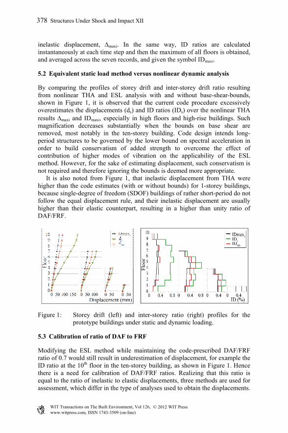
inelastic displacement, maxi. In the same way, ID ratios are calculated instantaneously at each time step and then the maximum of all floors is obtained, and averaged across the seven records, and given the symbol IDmaxi.
5.2 Equivalent static load method versus nonlinear dynamic analysis
By comparing the profiles of storey drift and inter-storey drift ratio resulting from nonlinear THA and ESL analysis with and without base-shear-bounds, shown in Figure 1, it is observed that the current code procedure excessively overestimates the displacements (ds) and ID ratios (IDs) over the nonlinear THA results maxi and IDmaxi, especially in high floors and high-rise buildings. Such magnification decreases substantially when the bounds on base shear are removed, most notably in the ten-storey building. Code design intends long-period structures to be governed by the lower bound on spectral acceleration in order to build conservatism of added strength to overcome the effect of contribution of higher modes of vibration on the applicability of the ESL method. However, for the sake of estimating displacement, such conservatism is not required and therefore ignoring the bounds is deemed more appropriate. It is also noted from Figure 1, that inelastic displacement from THA were higher than the code estimates (with or without bounds) for 1-storey buildings, because single-degree of freedom (SDOF) buildings of rather short-period do not follow the equal displacement rule, and their inelastic displacement are usually higher than their elastic counterpart, resulting in a higher than unity ratio of DAF/FRF.
Figure 1: Storey drift (left) and inter-storey ratio (right) profiles for the prototype buildings under static and dynamic loading.
5.3 Calibration of ratio of DAF to FRF
Modifying the ESL method while maintaining the code-prescribed DAF/FRF ratio of 0.7 would still result in underestimation of displacement, for example the ID ratio at the 10th floor in the ten-storey building, as shown in Figure 1. Hence there is a need for calibration of DAF/FRF ratios. Realizing that this ratio is equal to the ratio of inelastic to elastic displacements, three methods are used for assessment, which differ in the type of analyses used to obtain the displacements.
378 Structures Under Shock and Impact XII
www.witpress.com, ISSN 1743-3509 (on-line) WIT Transactions on The Built Environment, Vol 126, © 201 WIT Press2
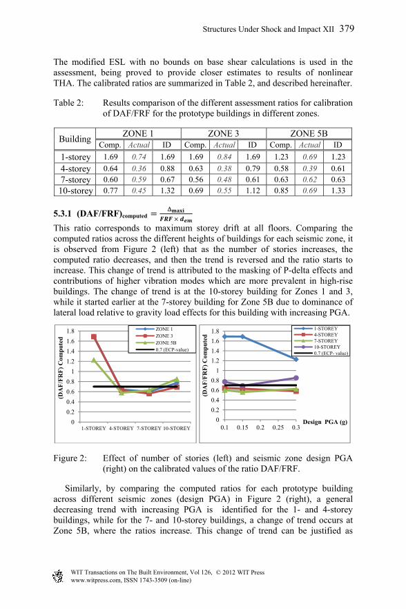
The modified ESL with no bounds on base shear calculations is used in the assessment, being proved to provide closer estimates to results of nonlinear THA. The calibrated ratios are summarized in Table 2, and described hereinafter.
Table 2: Results comparison of the different assessment ratios for calibration of DAF/FRF for the prototype buildings in different zones.
BuildingZONE 1 ZONE 3 ZONE 5B
Comp. Actual ID Comp. Actual ID Comp. Actual ID
1-storey 1.69 0.74 1.69 1.69 0.84 1.69 1.23 0.69 1.23
4-storey 0.64 0.36 0.88 0.63 0.38 0.79 0.58 0.39 0.61
7-storey 0.60 0.59 0.67 0.56 0.48 0.61 0.63 0.62 0.63
10-storey 0.77 0.45 1.32 0.69 0.55 1.12 0.85 0.69 1.33
5.3.1 (DAF/FRF)computed
This ratio corresponds to maximum storey drift at all floors. Comparing the computed ratios across the different heights of buildings for each seismic zone, it is observed from Figure 2 (left) that as the number of stories increases, the computed ratio decreases, and then the trend is reversed and the ratio starts to increase. This change of trend is attributed to the masking of P-delta effects and contributions of higher vibration modes which are more prevalent in high-rise buildings. The change of trend is at the 10-storey building for Zones 1 and 3, while it started earlier at the 7-storey building for Zone 5B due to dominance of lateral load relative to gravity load effects for this building with increasing PGA.
Figure 2: Effect of number of stories (left) and seismic zone design PGA (right) on the calibrated values of the ratio DAF/FRF.
Similarly, by comparing the computed ratios for each prototype building across different seismic zones (design PGA) in Figure 2 (right), a general decreasing trend with increasing PGA is identified for the 1- and 4-storey buildings, while for the 7- and 10-storey buildings, a change of trend occurs at Zone 5B, where the ratios increase. This change of trend can be justified as
0
0.2
0.4
0.6
0.8
1
1.2
1.4
1.6
1.8
1-STOREY 4-STOREY 7-STOREY 10-STOREY
(DA
F/F
RF
) C
omp
ute
d
ZONE 1ZONE 3ZONE 5B0.7 (ECP-value)
0
0.2
0.4
0.6
0.8
1
1.2
1.4
1.6
1.8
0.1 0.15 0.2 0.25 0.3
(DA
F/F
RF
) C
omp
ute
d
Design PGA (g)
1-STOREY4-STOREY7-STOREY10-STOREY0.7 (ECP- value)
Structures Under Shock and Impact XII 379
www.witpress.com, ISSN 1743-3509 (on-line) WIT Transactions on The Built Environment, Vol 126, © 201 WIT Press2

explained before. In general the calibrated ratios are found to be close to the 0.7 value specified by the code with the exception of single-storey buildings.
5.3.2 (DAF/FRF)actual @
The term actual corresponds to reflecting only the actual effect of inelastic excursion on displacement without other influencing factors such as higher mode effects, p-delta effects or diversion of lateral load distribution from ESL assumptions, because both inelastic and elastic displacements used are obtained from THA analysis. This ratio has been covered extensively in previous studies and is only shown to illustrate the significance of the current research. Actual DAF/FRF ratios are found to be much lower than those computed due to missing some of the factors inherent in the design process assumptions.
5.3.3 (DAF/FRF)ID
The DAF/FRFID ratios are higher than the corresponding DAF/FRFcomputed ratios in multi-storey buildings, consistent with findings of other researchers [7]. The increase in values is due to the occurrence of maximum and minimum storey drifts at two consecutive floors at an instant. The trends observed among different heights and different zones are similar to those for the DAF/FRFcomputed.
5.4 Effect of trading strength and stiffness on calibrated ratios of DAF/FRF
The trading of strength with stiffness by increasing member dimensions in return for decreasing steel reinforcement has a dual effect on drift of structures. Decreasing steel reduces the ductility and displacement demand, while increasing cross-section sizes of members result in shortening of the period of vibration and may attract higher lateral forces ultimately resulting in increased drift. This effect is investigated for the four prototype buildings in Zone 5B, where they are designed and analyzed with larger member dimensions and less reinforcement. Results of base shear and displacement analysis are presented in Table 3, and one can refer to [15] for details of reinforcement, design and modelling. The study shows that for the low-rise 1- and 4- storey buildings, DAF/FRFcomputed ratios are higher for stiffer structures, because the shortening of the period of vibration dragged the structures to the constant acceleration
Table 3: Comparison of displacement analysis results for the base-case and the higher stiffness scenarios for the four prototype buildings in Zone 5B.
Building Base Shear (KN) (DAF/FRF)computed (DAF/FRF)ID Base Stiff Base Stiff Base Stiff
1-storey 912.20 872.67 1.23 1.38 1.23 1.38 4-storey 1589.4 2131.1 0.58 0.93 0.61 0.93 7-storey 1841.4 2194.1 0.63 0.59 0.63 0.59
10-storey 2141.9 2491.8 0.85 0.76 1.33 0.89
380 Structures Under Shock and Impact XII
www.witpress.com, ISSN 1743-3509 (on-line) WIT Transactions on The Built Environment, Vol 126, © 201 WIT Press2
segment of the response spectrum in which the inelastic displacements may exceed the elastic ones. For the higher-rise 7- and 10-storey buildings, the shortened period still remains in the constant velocity region, and therefore the effect of reduced ductility demand prevails and results in decreasing DAF/FRF.
6 Summary and conclusion
The drift provisions of the ECP-201 [3] ESL method were evaluated by comparing their displacement results to displacement demands resulting from nonlinear THA under a suite of seven artificial ground motion records scaled to cover a range of seismicity in Egypt. The study involved examining the effect of disregarding the code stipulated upper bound on fundamental period and lower bound on spectral acceleration on bridging the gap between the actual maximum inelastic displacement (as best approximated by inelastic THA) and those estimated by the code, confirming the better suitability of ignoring these bounds for drift checks while enforcing them only for strength design. Accordingly ratios of DAF/FRF were calibrated, employing 224 THA runs on 2-D models of the structures. The proposed calibrated ratios after grouping are: for single-storey buildings: 1.7; for buildings between four and seven floors: 0.65 and 0.9 for estimation of separation distances and inter-storey drift checks respectively; and similarly 0.85 and 1.33 for buildings between seven and ten floors. The use of the proposed adjustment in drift provisions can result in better estimates of displacement and thus reduction in cost due to reduced member dimensions, separation distances between buildings and size of expansion joints. The results also show that by increasing member dimensions versus reinforcing steel, the DAF/FRF ratios increase for the 1- and 4-storey buildings due to dominance of the effect of shortening of the period of vibration and decrease for the 7- and 10-storey buildings due to dominance of the effect of reduced ductility. It is nonetheless important to note that this study and the conclusions herein are limited to the models and assumptions adopted, and cannot be extended for other structural systems, higher heights, and different site conditions without prior validation using similar studies.
Acknowledgement
The Mid-America earthquake Center and the National Science Foundation (Award Number EEC-9701785) are acknowledged for the use of ZEUS-NL [16].
References
[1] Freeman, S. A. and Searer, G. R., Design drift requirements for long-period structures. 13th World Conf. on Earthquake Engineering: Vancouver, Canada, A, paper No. 3292, 2004.
[2] Rosenblueth, E., and Meli, R., The 1985 Earthquake: causes and effects in Mexico City. Concrete International, 8(5), pp. 23-34, May1986.
Structures Under Shock and Impact XII 381
www.witpress.com, ISSN 1743-3509 (on-line) WIT Transactions on The Built Environment, Vol 126, © 201 WIT Press2

[3] ECP– 201, Egyptian Code of Practice no-201 for Design Loads for Construction. Housing &Construction Research Centre: Cairo, 2008.
[4] EC8- EuroCode 8-Design of Structures for Earthquake Resistance. Part 1: General rules, seismic actions and rules for buildings: CEN, Brussels, 2004.
[5] Uang, C. M., Establishing R (or RW) and Cd factors for building seismic provisions. Jr. of Structural Engin., 117 (1), pp. 19-28, 1991.
[6] NBCC, National Building Code of Canada. National Research Council of Canada: Ottawa, Ontario, Canada, 2005.
[7] Uang, C.M. and Maarouf, A., Deflection amplification factor for seismic design provisions. Jr. of Structural Engin.,120 (8), pp. 2423-2436, 1994.
[8] UBC, Uniform Building Code. International conference of building officials (ICBO): Whittier, CA, USA, 1997.
[9] Freeman, S.A. and Searer, G. R., Impact of the revised earthquake drift provisions on design and construction. Proceedings SEAOC 2000 Convention: Sacramento, California, 2000.
[10] ElKassas, S.H. and Haroun, M.A., Estimation method of inelastic displacement demands of moment resisting-frame buildings in moderate seismic zones. Proc. of the 2nd Int. Eng. Mechanics and Materials Specialty Conf.: Ottowa, Canada, paper No. EM-056, 2011
[11] ASCE7-05, Minimum design loads for buildings and other structures. SEI/ASCE 7-05: Reston, 2005.
[12] IBC, International Building Code. International Code Council: Birmingham, Alabama, 2000.
[13] CSI, Computers and Structures Inc., SAP 2000 program, version 14.0, Berkeley, CA, 2003.
[14] ECP – 203, Egyptian Code of Practice no-203 for Design &Construction of Concrete Structures. Housing &Construction Research Centre: Cairo, 2007.
[15] ElKassas, S.H., Calibration of displacement amplification factor for RC ordinary moment-resisting frame buildings. M.Sc Thesis, American University in Cairo: Egypt, 2010.
[16] ElNashai, A. S., Papanikolau, V., and Lee D. H., Zeus Non-linear: A system for inelastic analysis of structures. User Manual, version 1.8.7: Urbana-Champaign, IL, 2003.
[17] Mander, J.B., Priestley, M.J.N., and Park, R., Theoretical stress-strain model for confined concrete. Jr. of Structural Engineering, ASCE, 114 (8), pp.1804-1826, 1988.
[18] Martinez-Rueda, J.E. and ElNashai, A.S., Confined concrete model under cyclic load. Materials and Structures, 30 (197), pp. 139-147, 1997.
[19] ElNashai, A. S. and Izzuddin, B. A., Modeling of material non-linearities in steel structures subjected to transient dynamic loading. Earthquake Engin. & Structural Dynamics, 22, pp.509-532, 1993.
[20] Vanmarcke, Erik H., Cornell, C. Allin, Gasparini, Dario A. and Hou, Shou-nien, SIMQKE a Program for Artificial Motion Generation, MIT, 1979.
382 Structures Under Shock and Impact XII
www.witpress.com, ISSN 1743-3509 (on-line) WIT Transactions on The Built Environment, Vol 126, © 201 WIT Press2