evaluating and improving reverse engineering toolsflajos/lajosjenofulop_thesis.pdf · the...
TRANSCRIPT
Evaluating and Improving Reverse
Engineering Tools
Lajos Jen® Fülöp
Department of Software EngineeringUniversity of Szeged
Supervisor: Dr. Tibor Gyimóthy
June 2011Szeged, Hungary
A thesis submitted for the degree of doctor of philosophy
of the University of Szeged
University of SzegedPh.D. School in Computer Science


Preface
Developers tend to leave some important steps and actions (e.g. properly designingthe system's architecture, code review and testing) out of the software developmentprocess, and use risky practices (e.g. the copy-paste technique) so that the software canbe released as fast as possible. However, these practices may turn out to be critical fromthe viewpoint of maintainability of the software system. In such cases, a cost-e�ectivesolution might be to re-engineer the system.
Re-engineering consists of two stages, namely reverse-engineering information from thecurrent system and, based on this information, forward-engineering the system to anew form. In this way, successful re-engineering signi�cantly depends on the reverseengineering phase. Therefore, it is vital to guarantee correctness, and to improve theresults of the reverse engineering step. Otherwise, the re-engineering of the softwaresystem could fail due to the bad results of reverse engineering.
The above issues motivated us to develop a method which extends and improves one ofour reverse engineering tools, and to develop benchmarks and to perform experimentson evaluating and comparing reverse engineering tools.
Lajos Jen® Fülöp, 2011
iii


�To discover new continents,you must be willing to lose sight of the shore.�
Brian Tracy
Acknowledgements
This quote above expresses well how a person might feel when he starts his researchwork. I have been very lucky during my journey to the �new continent� because severalpeople helped me with their comments, ideas and suggestions and this improved not justmy work, but also opened my mind and broadened my knowledge. I am really gratefulto all those who helped my journey and I would not be where I am now without you all.
First, I would like to thank my supervisor Dr. Tibor Gyimóthy who helped me in mywork by providing useful ideas, comments and interesting research directions. I wouldlike to thank my article co-author and mentor, Dr. Rudolf Ferenc, for guiding mystudies and teaching me a lot of indispensable things about research. Without hisvaluable advice and hints I would never have acquired the research�oriented attitudethat I have. My many thanks also go to my colleagues and article co-authors, namelyDr. Árpád Beszédes, Tibor Bakota, Dr. István Siket, Dr. Judit Jász, Péter Siket,Péter Heged¶s, Dr. Lajos Schrettner, Dr. Tamás Gergely, Dr. László Vidács, GyörgyHeged¶s, Dr. Günter Kniesel, Alexander Binun, Dr. Alexander Chatzigeorgiou, Dr.Yann-Gaël Guéhéneuc, Dr. Nikolaos Tsantalis, Gabriella Kakuja-Tóth, Hunor Demeter,Csaba Nagy, Ferenc Fischer, Árpád Ilia, Ádám Zoltán Végh, Róbert Rácz, Lóránt Farkas,Fedor Szokody, Zoltán Sógor, Gábor Lóki, János Lele, Tamás Gyovai, Tibor Horváth andJános Pánczél. I would also like to thank the anonymous reviewers of my papers fortheir useful comments and suggestions. And I would like to express my thanks to DavidP. Curley for reviewing and correcting my work from a linguistic point of view. I wouldlike to thank my mother for her continuous support and encouragement. Last, but notleast, my heartfelt thanks goes to my wife Márti for providing a vital, a�ectionate andsupportative background during the time spent writing this work.
Lajos Jen® Fülöp, 2011
v


Contents
Preface iii
Acknowledgements v
List of Figures xii
List of Tables xiv
1 Introduction 1
1.1 Summary by chapters . . . . . . . . . . . . . . . . . . . . . . . . . . . 4
1.2 Summary by results . . . . . . . . . . . . . . . . . . . . . . . . . . . . 6
2 Background 11
2.1 Reverse engineering . . . . . . . . . . . . . . . . . . . . . . . . . . . . 11
2.2 Terminology . . . . . . . . . . . . . . . . . . . . . . . . . . . . . . . . 14
2.3 Columbus framework . . . . . . . . . . . . . . . . . . . . . . . . . . . . 16
I A proposed method for improving design pattern mining 19
3 Improvement of an existing design pattern miner tool 21
3.1 The learning process . . . . . . . . . . . . . . . . . . . . . . . . . . . . 22
3.2 Predictors . . . . . . . . . . . . . . . . . . . . . . . . . . . . . . . . . 23
3.2.1 Adapter object . . . . . . . . . . . . . . . . . . . . . . . . . . . 24
3.2.2 Strategy . . . . . . . . . . . . . . . . . . . . . . . . . . . . . . 25
3.3 Machine learning approaches used . . . . . . . . . . . . . . . . . . . . . 26
3.4 Results . . . . . . . . . . . . . . . . . . . . . . . . . . . . . . . . . . . 27
3.4.1 Adapter object candidates investigation . . . . . . . . . . . . . . 28
3.4.2 Strategy candidates investigation . . . . . . . . . . . . . . . . . 29
3.4.3 Learning e�ciency . . . . . . . . . . . . . . . . . . . . . . . . . 30
3.5 Summary . . . . . . . . . . . . . . . . . . . . . . . . . . . . . . . . . . 32
vii

viii Contents
II Evaluation of design pattern miner tools 33
4 Performance evaluation of design pattern miner tools 35
4.1 Framework . . . . . . . . . . . . . . . . . . . . . . . . . . . . . . . . . 354.1.1 CrocoPat . . . . . . . . . . . . . . . . . . . . . . . . . . . . . . 35
4.2 A comparative approach . . . . . . . . . . . . . . . . . . . . . . . . . . 364.3 Results . . . . . . . . . . . . . . . . . . . . . . . . . . . . . . . . . . . 38
4.3.1 Discovered pattern candidates . . . . . . . . . . . . . . . . . . . 394.3.2 Pattern mining speed . . . . . . . . . . . . . . . . . . . . . . . 444.3.3 Memory requirements . . . . . . . . . . . . . . . . . . . . . . . 47
4.4 Summary . . . . . . . . . . . . . . . . . . . . . . . . . . . . . . . . . . 48
5 Validation of design pattern miner tools 49
5.1 Benchmark . . . . . . . . . . . . . . . . . . . . . . . . . . . . . . . . . 505.1.1 Architecture . . . . . . . . . . . . . . . . . . . . . . . . . . . . 505.1.2 Fundamental participants and siblings . . . . . . . . . . . . . . . 525.1.3 Upload �le format. . . . . . . . . . . . . . . . . . . . . . . . . . 545.1.4 Benchmark contents . . . . . . . . . . . . . . . . . . . . . . . . 55
5.2 Usage scenarios . . . . . . . . . . . . . . . . . . . . . . . . . . . . . . 565.2.1 Browsing the database . . . . . . . . . . . . . . . . . . . . . . . 565.2.2 Evaluating and comparing tools . . . . . . . . . . . . . . . . . . 615.2.3 Adding a new tool . . . . . . . . . . . . . . . . . . . . . . . . . 62
5.3 Experiments performed . . . . . . . . . . . . . . . . . . . . . . . . . . 645.3.1 Reference implementations . . . . . . . . . . . . . . . . . . . . 675.3.2 NotePad++ . . . . . . . . . . . . . . . . . . . . . . . . . . . . 695.3.3 FormulaManager . . . . . . . . . . . . . . . . . . . . . . . . . . 71
5.4 Evaluation of the benchmark . . . . . . . . . . . . . . . . . . . . . . . 735.5 Summary . . . . . . . . . . . . . . . . . . . . . . . . . . . . . . . . . . 74
6 Common format for design pattern miner tools 75
6.1 Background . . . . . . . . . . . . . . . . . . . . . . . . . . . . . . . . 766.1.1 Motivation . . . . . . . . . . . . . . . . . . . . . . . . . . . . 766.1.2 Requirements . . . . . . . . . . . . . . . . . . . . . . . . . . . 766.1.3 State of the art . . . . . . . . . . . . . . . . . . . . . . . . . . 77
6.2 DPDX concepts . . . . . . . . . . . . . . . . . . . . . . . . . . . . . . 796.2.1 Speci�cation . . . . . . . . . . . . . . . . . . . . . . . . . . . . 796.2.2 Reproducibility . . . . . . . . . . . . . . . . . . . . . . . . . . . 806.2.3 Justi�cation . . . . . . . . . . . . . . . . . . . . . . . . . . . . 806.2.4 Completeness . . . . . . . . . . . . . . . . . . . . . . . . . . . 806.2.5 Identi�cation of role players . . . . . . . . . . . . . . . . . . . . 806.2.6 Language independence . . . . . . . . . . . . . . . . . . . . . . 826.2.7 Identi�cation of candidates . . . . . . . . . . . . . . . . . . . . 82

Contents ix
6.2.8 Comparability . . . . . . . . . . . . . . . . . . . . . . . . . . . 856.3 DPDX meta-models . . . . . . . . . . . . . . . . . . . . . . . . . . . . 85
6.3.1 Schema metamodel . . . . . . . . . . . . . . . . . . . . . . . . 856.3.2 Program element metamodel . . . . . . . . . . . . . . . . . . . 876.3.3 Result metamodel . . . . . . . . . . . . . . . . . . . . . . . . . 88
6.4 DPDX implementation . . . . . . . . . . . . . . . . . . . . . . . . . . 896.4.1 Implementation details . . . . . . . . . . . . . . . . . . . . . . . 906.4.2 Integration and visualization . . . . . . . . . . . . . . . . . . . . 91
6.5 Summary . . . . . . . . . . . . . . . . . . . . . . . . . . . . . . . . . 91
III Evaluation of reverse engineering tools 93
7 Validation of reverse engineering tools 95
7.1 Background . . . . . . . . . . . . . . . . . . . . . . . . . . . . . . . . 957.1.1 Sibling relation . . . . . . . . . . . . . . . . . . . . . . . . . . . 96
7.2 Use scenarios . . . . . . . . . . . . . . . . . . . . . . . . . . . . . . . . 1017.2.1 Setting up the database . . . . . . . . . . . . . . . . . . . . . . 1017.2.2 Data evaluation . . . . . . . . . . . . . . . . . . . . . . . . . . 105
7.3 Experimental results . . . . . . . . . . . . . . . . . . . . . . . . . . . . 1107.4 Summary . . . . . . . . . . . . . . . . . . . . . . . . . . . . . . . . . . 112
8 Conclusions 115
Appendices 119
Appendix A Related Work 119
A.1 Design pattern mining . . . . . . . . . . . . . . . . . . . . . . . . . . . 119A.2 Improvement of design pattern mining . . . . . . . . . . . . . . . . . . 121A.3 Evaluation of reverse engineering tools . . . . . . . . . . . . . . . . . . 122
Appendix B DPDX 127
B.1 Output formats of DPD tools . . . . . . . . . . . . . . . . . . . . . . . 127B.2 DPDX attribute values . . . . . . . . . . . . . . . . . . . . . . . . . . . 131B.3 DPDX implementation examples . . . . . . . . . . . . . . . . . . . . . . 134
Appendix C Summary 139
C.1 Summary in English . . . . . . . . . . . . . . . . . . . . . . . . . . . . 139C.2. Summary in Hungarian . . . . . . . . . . . . . . . . . . . . . . . . . . . 142
Bibliography 145


List of Figures
2.1 The reengineering process. . . . . . . . . . . . . . . . . . . . . . . . . . 122.2 Concept map of the most frequent terms of the thesis. . . . . . . . . . . 142.3 The State design pattern. . . . . . . . . . . . . . . . . . . . . . . . . . 152.4 The Columbus framework . . . . . . . . . . . . . . . . . . . . . . . . . 17
3.1 The learning process . . . . . . . . . . . . . . . . . . . . . . . . . . . . 233.2 The Adapter Object design pattern . . . . . . . . . . . . . . . . . . . . 243.3 The Strategy design pattern . . . . . . . . . . . . . . . . . . . . . . . . 25
4.1 Common framework . . . . . . . . . . . . . . . . . . . . . . . . . . . . 364.2 Factory Method pattern in RML . . . . . . . . . . . . . . . . . . . . . . 37
5.1 Architecture of Trac . . . . . . . . . . . . . . . . . . . . . . . . . . . . 505.2 Overview of DEEBEE . . . . . . . . . . . . . . . . . . . . . . . . . . . 515.3 State example . . . . . . . . . . . . . . . . . . . . . . . . . . . . . . . 535.4 CSV �le for the T1-2 candidate of the previous example . . . . . . . . . 555.5 Functionalities of the benchmark . . . . . . . . . . . . . . . . . . . . . 575.6 Query view of DEEBEE . . . . . . . . . . . . . . . . . . . . . . . . . . 575.7 Results view of DEEBEE . . . . . . . . . . . . . . . . . . . . . . . . . . 585.8 Instance view with highlighted source code in DEEBEE . . . . . . . . . . 595.9 Instance view statistics in DEEBEE . . . . . . . . . . . . . . . . . . . . 605.10 Statistics view of DEEBEE . . . . . . . . . . . . . . . . . . . . . . . . 615.11 Comparison view of DEEBEE . . . . . . . . . . . . . . . . . . . . . . . 635.12 Adding the results of a new tool to DEEBEE . . . . . . . . . . . . . . . 645.13 Framework for design pattern mining . . . . . . . . . . . . . . . . . . . 655.14 Reference implementation of Adapter Object . . . . . . . . . . . . . . . 665.15 Visitor candidate mined by Maisa from reference implementations . . . . 685.16 Comparison of candidates in reference implementations . . . . . . . . . . 70
6.1 A federation of design pattern detection, visualization and assessmenttools cooperating via the common exchange format. . . . . . . . . . . . 76
6.2 Named and unnamed elements example . . . . . . . . . . . . . . . . . . 816.3 Illustration of candidates . . . . . . . . . . . . . . . . . . . . . . . . . . 84
xi

xii List of Figures
6.4 Relation between schemata, diagnostics and instances . . . . . . . . . . 856.5 Metamodel of design pattern schemata . . . . . . . . . . . . . . . . . . 866.6 Sample of design pattern schemata . . . . . . . . . . . . . . . . . . . . 866.7 Metamodel of program element identi�ers and optional source locations . 876.8 Representation of the invocation a.f(d,c) from the code example in Fig-
ure 6.2 . . . . . . . . . . . . . . . . . . . . . . . . . . . . . . . . . . . 886.9 Metamodel of the design pattern detection results . . . . . . . . . . . . 886.10 A decorator instance from the java.io package of the JDK with subclasses
implemented by us (OutputStreamWriter and CharCountBu�erWriter) . . 896.11 Sample of the design pattern detection results . . . . . . . . . . . . . . 89
7.1 Example code for contain and overlap functions . . . . . . . . . . . . . . 977.2 Problem of the non-transitivity feature of the sibling relation . . . . . . . 1017.3 Creating a new domain . . . . . . . . . . . . . . . . . . . . . . . . . . 1027.4 Correctness criteria . . . . . . . . . . . . . . . . . . . . . . . . . . . . . 1037.5 Uploading data into BEFRIEND . . . . . . . . . . . . . . . . . . . . . . 1047.6 Sibling settings . . . . . . . . . . . . . . . . . . . . . . . . . . . . . . . 1057.7 Query view . . . . . . . . . . . . . . . . . . . . . . . . . . . . . . . . . 1067.8 Results view . . . . . . . . . . . . . . . . . . . . . . . . . . . . . . . . 1067.9 Group instance view . . . . . . . . . . . . . . . . . . . . . . . . . . . . 1077.10 Bauhaus correctness statistics . . . . . . . . . . . . . . . . . . . . . . . 1097.11 Comparison view . . . . . . . . . . . . . . . . . . . . . . . . . . . . . . 110
B.1 Output format of SPQR . . . . . . . . . . . . . . . . . . . . . . . . . . 127B.2 Output format of Fujaba . . . . . . . . . . . . . . . . . . . . . . . . . . 128B.3 Output format of Maisa . . . . . . . . . . . . . . . . . . . . . . . . . . 128B.4 Output format of SSA . . . . . . . . . . . . . . . . . . . . . . . . . . . 128B.5 Output format of Columbus . . . . . . . . . . . . . . . . . . . . . . . . 129B.6 Output format of PINOT . . . . . . . . . . . . . . . . . . . . . . . . . 129B.7 Output format of Ptidej . . . . . . . . . . . . . . . . . . . . . . . . . . 129B.8 Input format of DEEBEE . . . . . . . . . . . . . . . . . . . . . . . . . 129B.9 Format of PMART . . . . . . . . . . . . . . . . . . . . . . . . . . . . . 130B.10 Implementation of the schema metamodel . . . . . . . . . . . . . . . . 134B.11 Implementation of the program metamodel - �rst part . . . . . . . . . . 135B.12 Implementation of the program metamodel - second part . . . . . . . . . 136B.13 Implementation of the result metamodel . . . . . . . . . . . . . . . . . 137

List of Tables
1.1 The relation between the thesis topics and the corresponding publications. 9
3.1 Pattern candidates . . . . . . . . . . . . . . . . . . . . . . . . . . . . . 273.2 Some predictor values for Adapter Object . . . . . . . . . . . . . . . . . 283.3 Some predictor values for Strategy . . . . . . . . . . . . . . . . . . . . 293.4 Average accuracy with standard deviation based on three-fold cross vali-
dation . . . . . . . . . . . . . . . . . . . . . . . . . . . . . . . . . . . 313.5 Learning statistics . . . . . . . . . . . . . . . . . . . . . . . . . . . . . 31
4.1 About the size of each project studied . . . . . . . . . . . . . . . . . . . 384.2 DC++ candidates . . . . . . . . . . . . . . . . . . . . . . . . . . . . . 394.3 WinMerge candidates . . . . . . . . . . . . . . . . . . . . . . . . . . . 404.4 Jikes candidates . . . . . . . . . . . . . . . . . . . . . . . . . . . . . . 414.5 Mozilla candidates . . . . . . . . . . . . . . . . . . . . . . . . . . . . . 424.6 Initialization times . . . . . . . . . . . . . . . . . . . . . . . . . . . . . 444.7 Initialization time - exporters . . . . . . . . . . . . . . . . . . . . . . . 444.8 WinMerge times . . . . . . . . . . . . . . . . . . . . . . . . . . . . . . 454.9 Jikes times . . . . . . . . . . . . . . . . . . . . . . . . . . . . . . . . . 464.10 Mozilla times . . . . . . . . . . . . . . . . . . . . . . . . . . . . . . . . 464.11 Memory requirements in megabytes . . . . . . . . . . . . . . . . . . . . 47
5.1 Distribution of uploaded candidates . . . . . . . . . . . . . . . . . . . . 565.2 Number of design pattern candidates found for Reference Implementations 675.3 Number of design pattern candidates found for NotePad++ . . . . . . . 715.4 Number of design pattern candidates found for FormulaManager . . . . . 72
6.1 Tools and requirements satis�ed by their output formats . . . . . . . . . 78
7.1 Contain and overlap values for the previous example . . . . . . . . . . . 997.2 Results on NotePad++ . . . . . . . . . . . . . . . . . . . . . . . . . . 1117.3 Results on JUnit . . . . . . . . . . . . . . . . . . . . . . . . . . . . . . 111
B.1 DP-Miner result . . . . . . . . . . . . . . . . . . . . . . . . . . . . . . 127B.2 Attribute values of DPDX . . . . . . . . . . . . . . . . . . . . . . . . . 131
xiii

xiv List of Tables
B.3 Property values . . . . . . . . . . . . . . . . . . . . . . . . . . . . . . . 131B.4 Program element hierarchy . . . . . . . . . . . . . . . . . . . . . . . . 133

To my wife,
Márti.

Chapter 1
Introduction
�You can't just ask customers what they wantand then try to give that to them. By the timeyou get it built, they'll want something new.�
Steve Jobs
The development of software systems usually includes their speci�cation, design, imple-mentation, testing, deployment and maintenance. The general tendency is that softwarecompanies tend to leave some of the steps (e.g. requirements analysis, speci�cation,design and testing) out of the software development process to release the software asfast as possible due to the tight deadlines. The problem is that these skipped stepsmay turn out to be crucial from the viewpoint of deployment and maintainability of thesoftware system.
For example, a �edgling software company is forced to release its �rst products as soon aspossible to gain some advantage in the market over its competitors. In this way, the �rstreleases are very frequent and fast, and if the company survives the initial di�culties it willrapidly grow into a medium-sized company. However, by that time the maintenance (e.g.satisfying new requests, �xing bugs, adapting to new platforms and environments) ofthe software becomes very expensive because nobody knows the concrete requirements,the architecture, and the key components of the system. Furthermore, several bugs maybe reported by customers because there were insu�cient resources to test the softwareduring the preceding releases. These reported bugs could seriously harm the company'sreputation. The situation is frequently made worse when the original developers leavethe company and then nobody knows how the system was implemented. In this way,a new software system can become a legacy system after a relatively short period oftime [25]. However, the company has to manage this crisis to survive in the market.
The company has two possibilities to manage the evolved crisis. It can either redevelopthe system from scratch or re-engineer the current legacy system.
Redeveloping a system is a really expensive and risky solution for several reasons. Firstof all, the legacy system has to be maintained before the new system is released to thecustomers. Maintaining the legacy system will cost as much as the original developmentbecause the customers should not feel any kind of e�ects. In this way, the company getsinto a similar situation as during the implementation of the legacy system. It will have
1

2 Introduction
insu�cient resources to collect the requirements, describe the speci�cation accurately,design the architecture and plan the test cases of the new system. It means that thecompany will get into the same trap as it was in in the case of the legacy system: justimplementing the new system without due care means that the current problems andcrisis will appear two or three years later. However, in certain cases it is better to re-implement a system from scratch, but this decision should be preceded by an in-depthevaluation of the current (legacy) system to see whether it has been re-engineered ornot.
Re-engineering a legacy software systems was brie�y summarized by Demeyer et. al. [25]:�The goal of reengineering is to reduce the complexity of a legacy system su�ciently
that it can continue to be used and adapted at an acceptable cost.� Most of the time,re-engineering a legacy system is unambiguously a better choice than rewriting it fromscratch for several reasons. First of all, several components of a legacy system are notcritical while others are modi�ed very rarely. Some components of the system are testedand, typically, most of them are the critical components of the system. Furthermore,the system is currently being used and functioning. On top of this, Demeyer et. al.proposed several patterns [25] that provide solutions to re-engineering legacy systemsincrementally and continuously in such a way that the customers of the system do notnotice anything. Therefore, in most cases it is much more cost-e�ective to re-engineera legacy system than to rewrite it from scratch.
Re-engineering consists of two stages, namely reverse engineering information from thecurrent (legacy) system and, based on this information, (forward) engineering the systeminto a new form. Reverse engineering applies techniques like analyzing the source code,interviewing developers, browsing the existing documentation, discovering the design andarchitecture, and identifying the problematic and the key parts of the system. However,most of the time the documentation is completely missing or if it exists it is quiteoutdated, and developers either do not know the system because they have only workedfor the company for a short time or they are afraid of providing the necessary information(e.g. bugs caused by them) about the system. Therefore only the source code of thelegacy system can be regarded as an objective starting point of reverse engineering. Inthis thesis, by the term reverse engineering we mean the reverse engineering of just the
source code.
Re-engineering constructs the system in a new form1 based on the results of reverseengineering. The re-engineered form of the system should have lower maintainabilitycosts. Successful re-engineering demands a really precise and really reliable reverseengineering of the legacy system because any kind of decision and activity during theforward engineering phase is based on this information. Hence it is very important toensure correctness, and to improve the results of the reverse engineering step, otherwise
1Refactoring is a well-known technique that applied in the �eld of software engineering.

3
the whole re-engineering project could be unsuccessful due to the false results of reverseengineering. It motivated us to develop a method which extends and improves one ofour reverse engineering tools, and to develop benchmarks and to perform experimentson evaluating and comparing reverse engineering tools.
Reverse engineering tools handle (i) source code parsing and extract an abstract modelfrom it and (ii) perform some exploratory operations on the abstract model. In thisthesis we will focus on the latter type of reverse engineering tools. Namely, we will dealwith design pattern miners, duplicated code detectors and rule violation checkers.
Design pattern mining tools help one to better understand the system and its compo-nents. By revealing patterns from the source code it is easier to understand how thecorresponding classes and methods interact and to work out why they communicate witheach other and what business logic is implemented by them. Duplicated code detectortools discover risky copied code fragments. These fragments could carry the same bugsand make the maintenance of the system di�cult, because all the fragments should bemodi�ed at the same time. Rule violation checkers audit typical programmer errors inthe source code. One such error might be comparing two Java String objects with the= operator instead of the equals method. These tools provide important informationabout the legacy system, but their results may contain false positives.
Up until now, research teams have focused on the improvement and evaluation of thetools. Petterson et al. [63], for instance, summarized problems during the evaluationof accuracy in design pattern detection, Bellon et al. [10] performed tests to evaluateand compare duplicated code detectors and Wagner et al. [88] compared three Javacoding rule checkers. Surprisingly, no author has yet proposed a general framework orbenchmark for comparing and evaluating the results of reverse engineering tools likedesign pattern miners, duplicated code detectors and rule violation checkers. In thisthesis, we will focus on these; especially on design pattern mining, how to improve andhow to evaluate design pattern miner tools. In the third part of the thesis we proposea benchmark for reverse engineering tools like design pattern miners, duplicated codedetectors and rule violation checkers, and show how it can be applied to real-life cases.

4 Introduction
1.1 Summary by chapters
The thesis contains three main parts. The �rst part (Chapter 3) presents a method forimproving design pattern mining and also the results of experiments using our designpattern miner tool. The second part (Chapters 4, 5 and 6) discusses techniques, formatsand experiments concerning the evaluation and comparison of design pattern miner tools.After, the third part of the thesis (Chapter 7) describes our general framework, which iscapable of evaluating and comparing reverse engineering tools.
Part I: An improvement method for design pattern mining
In the third chapter we shall brie�y describe our method for improving design patternmining. We utilized machine learning methods to further re�ne our pattern miner toolby marking the pattern candidates returned by the matching algorithm as either true orfalse. We de�ned predictors for two selected design patterns namely Adapter Object andthe Strategy. We performed our experiments on StarWriter [80].
Part II: Evaluation of design pattern miner tools
The fourth chapter describes a comparison and performance evaluation of three designpattern miner tools, namely Columbus, Maisa and Crocopat. Here we provide a com-parative approach for design pattern miners. The approach examines the performanceindicators (time, memory) and di�erences found between the results. Afterwards, thethree tools are evaluated based on this comparative approach. In this chapter, we do notfocus on the correctness issue of the results, but just systematize the common di�erencesamong tools.
Chapter 5 discusses the evaluation and comparison of design pattern miner tools con-cerning the correctness of the results. Here we elaborate on DEEBEE (DEsign patternEvaluation BEnchmark Environment), an online framework for evaluating and compar-ing results of design patter miner tools. When comparing the results, DEEBEE handlesproblems systematized previously in Chapter 3 by relating and grouping similar results ofthe tools. We will describe the interface of DEEBEE through meaningful usage scenariosand afterwards we will present the results of our experiments. Lastly, the benchmark isevaluated with regard to the requirements proposed by Sim et al. [74].
In the sixth chapter, we present a common output format, DPDX, for design patterndetector tools. A common output format is vital for a uniform evaluation and comparisonof the results. Here we de�ne requirements for the common output format and evaluatethe current format of design pattern miner tools according to these requirements. Then,we de�ne metamodels of the format that contains the schema metamodel, programmetamodel and results metamodel. After, we provide an XML-based implementation ofthis metamodel.

1.1 Summary by chapters 5
Part III: Evaluation of reverse engineering tools
In the seventh chapter, we present BEFRIEND (BEnchmark For Reverse engInEeringtools workiNg on source coDe), an online framework for evaluating and comparing reverseengineering tools. BEFRIEND is a generalized version of DEEBEE. Here we provide thetheoretical background needed for handling and grouping the results of di�erent reverseengineering tools. Then, we apply the BEFRIEND interface in representative usagescenarios. After, we will present the results of our experiments performed using thebenchmark.
In the last chapter we present conclusions and provide a short summary of the resultsobtained. In this chapter we also outline possible directions for future work.
Lastly, we round o� with appendices that contain related works, details of the DPDXformat and a brief summary of the principal results of the thesis in English and Hungar-ian.

6 Introduction
1.2 Summary by results
The main contributions of this work are summarized as follows. First, we introducea new technique for improving design pattern mining. Afterwards, we evaluate designpattern miners in terms of their speed, memory consumption and the di�erences in theirresults. Furthermore, we developed a publicly available online benchmark (DEEBEE)which supports the evaluation and comparison of design pattern miners by consideringtheir correctness and completeness. We also propose a common exchange format fordesign pattern miner tools that is based on a well-de�ned metamodel. Lastly, we gener-alize DEEBEE in BEFRIEND, which supports the evaluation and comparison of reverseengineering tools as well.
We state �ve key results in the thesis and the contributions of the author are clearlyshown in the listed results. As the thesis consists of three parts, the results are alsopresented in three parts.
Part I: An improvement method for design pattern mining
The result of the �rst part of the thesis is a machine learning-based method for improvingdesign pattern mining. This is described in Chapter 3 in detail.
1. Improvement of an existing design pattern miner tool.
Here we enhanced our design pattern miner tool called CAN2Dpm, which is acomponent of the Columbus framework [13]. We used machine learning methodsto further re�ne the pattern mining by marking the pattern candidates returned bythe matching algorithm as either true or false. In other words, we further �lteredthe pattern candidates returned via the original matching algorithm by eliminatingfalse hits. Our approach in a nutshell is to analyze the candidates returned bythe matching algorithm, taking into account various aspects of the candidatecode fragment and its neighbourhood, such as whether a participant class has aparent or not, or how many new methods a participant class de�nes besides aparticipating method. The information associated with these aspects is referred toas predictors, whose values can be used in a machine learning system for decisionmaking. We employ a conventional learning approach; that is, we �rst manuallytag the candidates as true or false and calculate the values of the predictors onthe candidates. Then we load these into some learning system (we conductedour experiments using two methods, namely a decision tree-based approach anda neural network approach). This in turn provides a model that incorporatesthe acquired knowledge, which can later be used for pattern mining in unknownsystems. In the current work we test the models with the cross-validation method.We performed our experiments on StarWriter [80] as the subject system for patternmining and we searched for the Adapter Object and the Strategy design patterns.

1.2 Summary by results 7
The author performed the experiments with the Strategy design pattern and manu-ally tagged the results of the design pattern mining tool in the case of the Strategydesign pattern.
Part II: Evaluation of design pattern miner tools
The second part of the thesis focuses on our experiences gained and tools developed forthe evaluation of design pattern miners. These are elaborated on in Chapters 4 and 5.This part also introduces a common exchange format (in Chapter 6) for design patternminer tools, which is needed to readily compare, evaluate, fuse and visualize the resultsof tools in a standard way.
2. Performance evaluation of design pattern miner tools.
Our aim here was to compare three design pattern miner tools; namely Columbus,Maisa and CrocoPat. We chose these tools because it was possible to prepare acommon input for them with our front end called Columbus. Earlier work by usenabled us to provide the input for Maisa [34], while in the case of CrocoPat wecreated a new plug-in for Columbus which can generate the right format. Next,the tools were compared from three aspects: di�erences between the hits, theirspeed and memory requirements. We think that these are important aspects for adesign pattern miner tool. We did not examine whether a design pattern hit wastrue or false, but just concentrated on structural hits and di�erences.
The author developed the Columbus-CrocoPat exporter and integrated it into theColumbus framework. He also de�ned several design patterns in the representationlanguage (RML) of CrocoPat. Furthermore, the author performed the experimentsand obtained the results presented in this thesis. The author also participated in�nding a concrete de�nition for the comparison-and-evaluation approach.
3. Validation of design pattern miner tools.
Here we present experiments performed on a newly developed benchmark for eval-uating and comparing design pattern miner tools. The benchmark is quite generalfrom the viewpoint of the mined software systems, programming languages, up-loaded design pattern candidates, and design pattern miner tools. With the helpof this benchmark, the accuracy of two design pattern miner tools (Columbus andMaisa) were evaluated on reference implementations of design patterns and on twosoftware systems called NotePad++ and FormulaManager. Here, design patterninstances in NotePad++ were also discovered by hand, so both the precision andrecall scores were calculated by the benchmark automatically. In addition, we de-veloped a software system called FormulaManager to test the tools on a programwhere each design pattern was implemented in a real-life context.
With the help of the benchmark one can evaluate design pattern miner tools, whichwill hopefully lead to better quality design pattern miner tools in the future. With

8 Introduction
this benchmark the results of a pattern miner tool should be quicker and easier toclassify.
The author developed the benchmark (except the instance view). He also de�nedand implemented the uploading format of the benchmark including the siblingand grouping mechanism. The author performed the experiments with Maisa andColumbus, and uploaded their results into the benchmark. He also participated indesigning the architecture of the benchmark, in determining the evaluation aspects,in manually tagging the results of the tools and in designing its use cases.
4. Common exchange format of design pattern miner tools
Here we present DPDX, a common exchange format for design pattern miner tools.First we de�ne the requirements for the output format of a design pattern minertool. Then, we examine the formats of existing tools based on the above-de�nedrequirements. After, taking into account the identi�ed problems of the existingformats, we analyze the requirements in detail to see how they may be ful�lledcompletely by the proposed format. Based on these experiments we propose awell-de�ned and extendible metamodel that addresses a number of limitations ofcurrent tools. The proposed metamodel is implemented in an XML-based languagethat can be easily adapted by existing and future tools, providing a means forimproving accuracy and recall scores when evaluating, comparing and combiningtheir �ndings.
The author developed the initial versions of the schema metamodel implementationand described the Maisa tool. He also participated in the substantial improvementand �nalization of the initial ideas (concepts, metamodel, implementation) in theireventual form.
Part III: Evaluation of reverse engineering tools
The results of the third part of the thesis include BEFRIEND, a general benchmark forreverse engineering tools. This is elaborated on in Chapter 7.
5. Validation of reverse engineering tools.
Here we introduce the further development of the DEEBEE system, which hasbecome more useful since we generalized the evaluation aspects and the type ofthe evaluated tools. The new system is called BEFRIEND (BEnchmark ForReverse engInEering tools workiNg on source coDe). With BEFRIEND, the resultsof reverse engineering tools from di�erent domains that recognize arbitrary aspectsof source code can be subjectively evaluated and compared with each other. Suchtools include design pattern miners, duplicated code detectors and coding ruleviolation checkers. BEFRIEND greatly di�ers from its predecessor in �ve aspects:

1.2 Summary by results 9
N o. [94] [95] [96] [97] [98] [99] [100] [101] [102]1. •2. •3. • • •4. • •5. • •
Table 1.1: The relation between the thesis topics and the corresponding publications.
(1) it permits uploading and evaluating results related to di�erent domains; (2) itpermits adding and deleting the evaluating aspects of the results in an arbitraryway; (3) it has a new user interface; (4) it generalizes the de�nition of siblingrelationships; and (5) it permits uploading �les in di�erent formats by adding theappropriate uploading plug-in.
The author adopted and generalized the theory of sibling relations and provided thecorresponding implementation. He also participated in de�ning the terminology,manually evaluating the candidates using the benchmark and in the presentationof the benchmark's architecture.
Lastly, Table 1.1 summarizes which publications cover which results of the thesis.


Chapter 2
Background
�An investment in knowledge pays the best interest.�
Benjamin Franklin
In this chapter we will provide the necessary background for chapters 3 to 8. First, inSection 2.1 we shall brie�y introduce the concept of reverse engineering and then inSection 2.2 we will clarify the terminology used in the thesis. After, in Section 2.3 wewill present the Columbus framework that will be applied several times later on.
2.1 Reverse engineering
Previously we discussed reverse engineering in the Introduction through a meaningfulexample of a company. In this example the importance of reverse engineering was alsodemonstrated. In this section we collect and present some formal de�nitions and termsused in reverse engineering.
Chikofsky and Cross [21] formally de�nes re-engineering in the following way:
�Reengineering is the examination and the alteration of a subject system toreconstitute it in a new form and the subsequent implementation of the newform.� [21]
As we said in the Introduction, re-engineering is based on two processes which are alsode�ned by Chikofsky and Cross:
�Reverse engineering is the process of analyzing a subject system to (a)identify the system's components and their interrelationships and (b) cre-ate representations of the system in another form or at a higher level ofabstraction.� [21]
�Forward engineering is the traditional process of moving from high-levelabstractions and logical, implementation-independent designs to the physicalimplementation of a system.� [21]
11
12 Background
Requirements New requirements
Designs
Code
Fo
rwa
rd e
ng
ine
erin
g
Reve
rse
en
gin
ee
rin
g
Reengineering
Figure 2.1: The reengineering process.
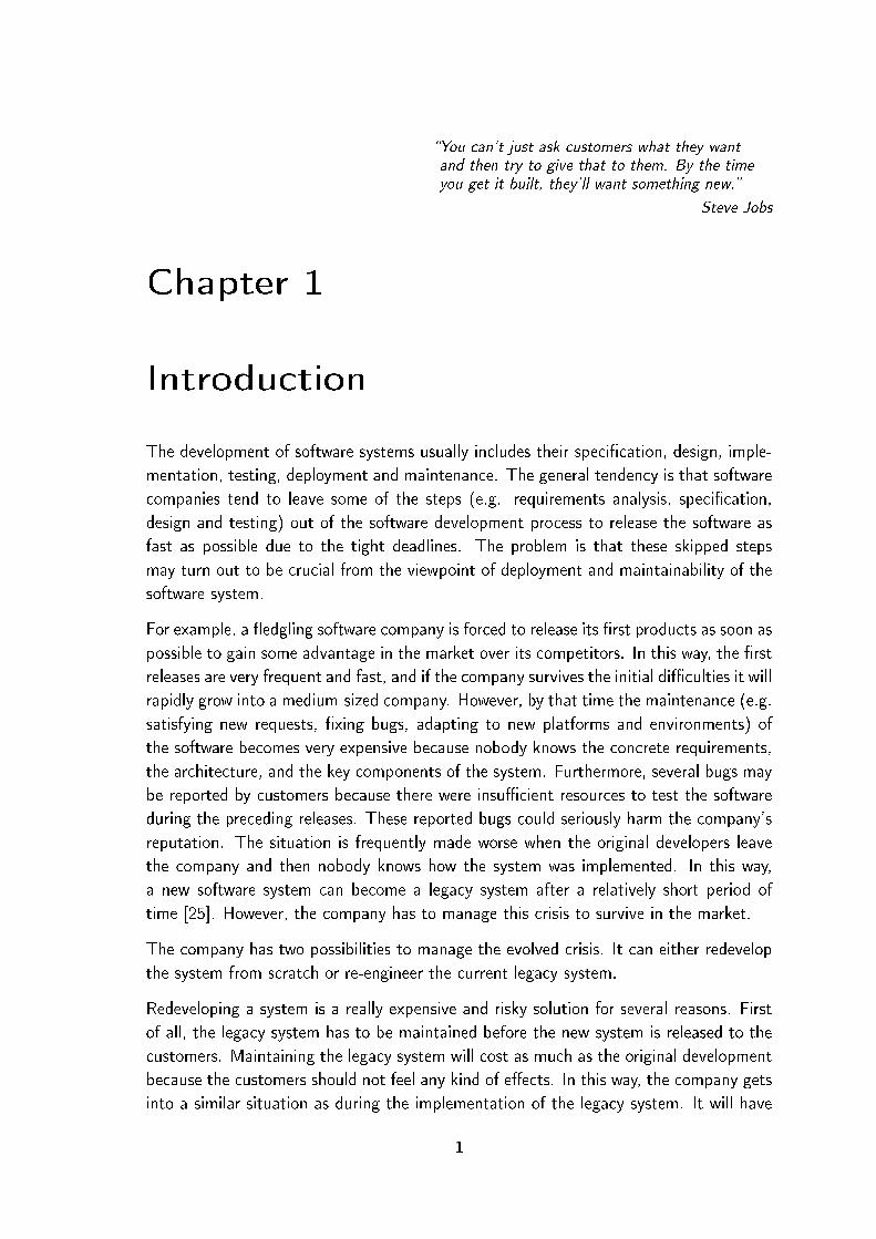
In [25], Demeyer et al. demonstrated in diagram form how reverse engineering andforward engineering work together in the re-engineering process (see Figure 2.1). Reverseengineering constructs a model from the source code. It represents information aboutthe source code, which, for example, helps us to understand the system (e.g. designpattern mining) and to discover concrete problems in the system (e.g. rule violationcheckers and duplicated code detectors). Based on the information provided by thereverse engineering process and on the new requirements of the system, the originaldesign can de�nitely be improved. For example, a duplicated code detector tool discoverscopied clone fragments that should be �xed. In this case, the problem is �rst �xed at thedesign level: the transformed model introduces a new method representing the commonfunctionality and the originally copied clone fragments are replaced with method callsto the new common method. Afterwards, the source code is updated based on thetransformed model.
Reverse engineering tools basically deal with two tasks. The �rst task is source codeparsing and extracting an abstract model from the source code, while the second oneis performing some exploratory operations on the abstract model. In this thesis we willdeal with the latter task of reverse engineering. Reverse engineering tools in this thesismean these kind of tools. Namely, we will deal with design pattern miners, duplicatedcode detectors and rule violation checkers. These three areas will now be described.
Design pattern miners The correct use of design patterns in software developmentis a commonly used premise for the good quality of the design in terms of - among otherthings - reusability and maintainability. Well-established and documented design patternsexist in various areas of software development. One of the most commonly recognizedpattern catalogues was compiled by Gamma et al. [39], which describes patterns used

2.1 Reverse engineering 13
in object-oriented analysis and design. Here, we will make use of these patterns. Mostof the systems contain occurrences of design patterns, irrespective of whether they areintroduced by the designer intentionally or unwittingly. Whatever the case, knowingabout the instances of patterns in a software system may be of great help during thesoftware maintenance phase (for example, to better understand the system's structureand workings). Unfortunately, in many cases the pattern usage is poorly documented, soduring the reverse engineering process the automatic or semi-automatic procedures usedfor discovering design patterns in undocumented software can be a great help if we wishto re-engineer the software. There are several tools available for discovering patterns inJava source code like Ptidej [42, 65] and Fujaba [37], and tools also exist for miningpatterns from C++ code like Columbus [8, 32]. However, the automatic recognition ofdesign patterns is indeterministic because design patterns convey concepts not concretesolutions. Gamma et al. [39] also proposed concrete solutions, but these solutions mayappear in the source code with another intent as well. Therefore, tools mining designpatterns produce a certain amount of false results which need to be �ltered out.
Duplicated Code Detectors Most developers know about the copy-paste method.The copy-paste technique means copying a certain code fragment and pasting it intoanother part of program code. The problem with this technique is that if the originalcode fragment contains bugs (errors) then the copied fragment will contain these bugsas well, hence the number of bugs immediately increases in the system. In addition,when the copied fragment has to be modi�ed then the copied fragments also have to bemodi�ed, but it usually not known where the copied fragments are located. However,developers tend to use this technique frequently because of tight deadlines. They useit because it seems quick and e�ective at �rst glance, but it carries a potential danger:every copied code fragment has to be modi�ed consistently in the future. In this way,this technique is a potential pitfall for the developer and for the company as well. Toaddress this problem, several duplicated code detector tools have been published (e.g.Bauhaus [9], CCFinder [19] and Simian [78]). However, detecting duplicated code is nota trivial task. Copied fragments are frequently modi�ed inconsistently, which will makedetection di�cult and problematic. Thus in practice duplicated code detector tools mayproduce some false results and miss some real clones.
Coding Rule Checkers Coding rules describe rules for programming. These rules arevarious and some rules relate to the coding style, while others relate to critical codingmistakes, which can cause runtime errors. For example, Basic Ruleset of PMD [64]contains the EmptyCatchBlock rule: �Empty Catch Block �nds instances where an
exception is caught, but nothing is done. In most circumstances, this swallows an
exception which should either be acted on or reported.� A coding rule violation occursif the programmer does not follow a certain rule and he violates it. Coding rule checker

14 Background
tools discover these violations in the given system. Several rule checkers exist such asPMD [64], CheckStyle [20], FindBugs [35] and FxCop [38].
The above are just examples of di�erent aspects of areas of reverse engineering. Wewill elaborate on these areas, especially that of the evaluation and comparison of designpattern miner tools.
2.2 Terminology
In this section the terminology that will be used throughout the thesis is clari�ed andsummarized. Based on the corresponding publications the clari�cation of terminologyshould be a part of chapters 6 and 7. However, it is much better to gather and presentthese terms at the beginning of the thesis to make everything clearer. Figure 2.2 showsthe most frequent terms used in the thesis.
Figure 2.2: Concept map of the most frequent terms of the thesis.
Reverse engineering tools can be classi�ed into domains. A domain groups tools withthe same aim e.g. design pattern miners, duplicated code detectors, or rule violationcheckers.
Each domain contains concepts which describe a concrete problem. For example, in thecase of the design pattern miner domain, one concept is the State design pattern. Theconcepts of this pattern were summarized by Gamma et al. [39] in terms of its intent, amotivation example and its applicability.

2.2 Terminology 15
Every concept has at least one solution. For example, in the case of the design patternminer domain, Gamma et al. [39] proposed a structure for the State design pattern (seeFigure 2.3). However, this structure can implemented in several ways, which we referto as solutions (e.g. aggregation between Context and State can be implemented witha simple reference or with a standard container). Moreover, certain implementations(solutions) can signi�cantly di�er from this implementation (e.g. Context and State arerepresented in one common class).
Figure 2.3: The State design pattern.
A solution contains roles. For example, the proposed structure of the State patterncontains the class level roles Context, State, and ConcreteState.
The tools in a given domain produce di�erent results that refer to one or more positionsin the source code being analyzed. We refer to these positions as result candidates.A certain tool discovers candidates based on the solution that was the basis of thediscovery process. However, in certain cases a discovered candidate does not correspondto the original concepts. In such cases we refer to the candidate as a false positive
or false hit. Otherwise, if the candidate corresponds to the original concepts then wewill refer it as a true positive, a true hit or an instance of the original concept. Humaninspection is required to decide whether a candidate matches the concepts and representsan instance or not. For example, Gamma et al. [39] proposed exactly the same structurefor State and Strategy patterns, which cause these patterns to have the same candidates.Only human inspection can decide whether a certain candidate is a Strategy or a Stateinstance. Candidates and instances may be categorized in the following way:
• True Positives (TP ): instances found by the tool (correctly).
• False Positives (FP ): false candidates reported by the tool (incorrectly).
• True Negatives (TN): false candidates not reported by the tool (correctly).
• False Negatives (FN): instances not found by the tool (incorrectly).

16 Background
Based on these aspects, the following two well-known statistics can calculated. Theprecision score is de�ned as TP
TP+FP× 100, which means the ratio of correctly identi�ed
instances over all found candidates. The recall score is de�ned as TPTP+FN
× 100, whichmeans the ratio of correctly identi�ed instances over all existing instances.
The candidates found include other elements which are called as participants. Partici-
pants correspond to the roles of the current solution.
The design pattern miner domain contains several concepts (design patterns), while theduplicated code detector domain contains just one (duplicated code). Similar to thedesign pattern miner domain, the rule violation checker domain also contains severalconcepts (empty catch block, broken null check, etc. [64]). However, roles and partici-
pants are only used for the design pattern mining domain.
Design patterns In this thesis we mainly focus on design pattern miner (DPM)1 tools.This is why we need to introduce additional terms and de�nitions for this area [99],[100].
A design pattern describes a recurring design problem. A design pattern includes at leastfour parts: a name, a problem, a structure, and the consequences of applying the pro-posed structure (see Gamma et al. [39]). The implemented solution of a design patternis a design motif (see [44]), which describes a prototypical set of classes and/or ob-jects collaborating to solve the design problem. A motif typically describes several roles,which must be ful�lled by program constituents (types, methods, �elds, etc.), their re-lations (inheritance, subtyping, association, etc.), and/or their collaborations (expressedin terms of code fragments or UML-like sequence diagrams). Roles can be mandatory or
optional [53].Mandatory roles(e.g. `State' in the `State' motif) represent the essence ofa motif. Optional roles might not be present in some instances (e.g. `Context' may bemissing). An instance of a design pattern P is a set of program constituents playing allthe mandatory roles (and possibly some or all the optional roles) in the motif of P. Pro-gram constituents playing the mandatory roles are called as fundamental participants. Acandidate of a design motif is a set of program constituents meant to form an instanceof the motif in the program and, generally, reported by a design pattern miner tool,which typically report candidates that they deem consistent with the design motif P.Although textbooks typically describe just one motif per design pattern in explicit detail,there may be several implementation variants for each pattern, thus several design motifs(solutions) need to be searched for by DPD tools.
2.3 Columbus framework
Some tools (the Columbus design pattern miner component, Maisa, CrocoPat) that willbe evaluated here have been integrated into the Columbus reverse engineering framework.
1The name design pattern detector (DPD) is a synonym for this.

2.3 Columbus framework 17
Moreover, our improvement of the design pattern miner component of the Columbusframework is also an important part of the thesis. Therefore, it is necessary to introducethe Columbus framework.
Columbus was developed in cooperation between FrontEndART Ltd., the University ofSzeged and the Software Technology Laboratory of Nokia Research Center. Columbusis able to analyze large C/C++ projects and to extract facts from them. The mainmotivation for developing the Columbus system was to create a general framework forcombining a number of reverse engineering tasks and to provide a common interfacefor them. Thus, Columbus is a framework tool which supports project handling, dataextraction, data representation, data storage, �ltering and visualization. All these basictasks of the reverse engineering process for the speci�c needs are accomplished by usingthe appropriate modules (plug-ins) of the system. Some of these plug-ins are providedas basic parts of Columbus, while the system can be extended to meet other reverseengineering requirements as well. This way we have a versatile and readily extendibletool for reverse engineering tasks.
Figure 2.4 shows the architecture of the Columbus framework with some components.First, Columbus (CAN) analyzes the source code and builds the corresponding repre-sentation (Abstract Semantic Graph � ASG) from it. Afterwards, the plugins load thisASG and they collect the necessary information by traversing the ASG. Lastly, the toolsgenerate their results.
Figure 2.4: The Columbus framework
One of the Columbus's plug-ins is CAN2Dpm, which discovers design patterns. Thedesign patterns were described in DPML (Design Pattern Markup Language) �les [8],which store information about the structures of the design patterns. Here CAN2Dpmseeks to match this graph to the ASG using our algorithm described in a previous work [8].
Maisa Maisa is a software tool [62] for the analysis of software architectures developedin a research project at the University of Helsinki. The key idea behind Maisa is to

18 Background
analyze design level UML diagrams and compute architectural metrics for the earlyquality assessment of a software system.
Maisa uses constraint satisfaction [56], which is a generic technique that can be appliedin a wide variety of tasks (in our case, to mining patterns from software architecturesor software code). A constraint satisfaction problem (CSP) is represented as a set ofvariables and a set of constraints that restrict the values that can be assigned to thesevariables. The language of Maisa's design pattern description is Prolog-like.
Maisa has also been integrated into the Columbus framework with the introduction ofthe CAN2Maisa plugin [33]. CAN2Maisa generates the appropriate input �le for Maisa.After, Maisa discovers design pattern candidates from this intermediate �le.

Part I
A proposed method for improving
design pattern mining
19


Chapter 3
Improvement of an existing design
pattern miner tool
�The question of whether computers can thinkis like the question of whether submarines can swim.�
Edsger W. Dijkstra
It is clear that recognizing design patterns is a crucial task of the software maintenanceprocess. In particular, design pattern mining supports the understanding of a softwaresystem by exposing the key participants. Moreover, it can partly make up for the miss-ing documentation, which is quite a common problem during software development.However, there is no guarantee that the results produced will be correct.
The problem with the more common approaches to pattern recognition (based on patternmatching) is that they are inherently too lax in the sense that they produce many falseresults, in which some code fragments are identi�ed as pattern candidates that shareonly the structure of the pattern description. This is due to the fact that the patternsthemselves are given using conventional object-oriented concepts, such as class diagramscontaining abstract classes and methods, generalization, polymorphism, decoupling con-crete responsibilities through references to abstract classes, and so on. This leads tostructures that are in many ways quite similar to each other (consider the structuresof, say, Bridge vs. Adapter Object1, Composite vs. Decorator or State vs. Strategy).Furthermore, such common structures may appear even for code fragments that werenot designed with the intent of representing any speci�c design pattern, but make use ofthe above-mentioned techniques simply as good object-oriented solutions to other prob-lems. The distinction between such true and false results and between di�erent patternswith the same structures can be made only by applying more sophisticated methods thatinvolve a deeper investigation of the implementation details and its environment, i. e. to�nd its real purpose.
In this chapter we propose a machine learning method and experiments on how to im-prove the results of design pattern miner tools to decide whether they are correct or
1The Adapter design pattern has two variants; namely a class version and an object version, whichdi�er in the way the adaptation is achieved; one is by using multiple inheritance, while the other is byobject composition.
21

22 Improvement of an existing design pattern miner tool
not. We applied the design pattern mining approach of our Columbus framework [8],but each experiment was repeated since both the C++ front end and the pattern min-ing algorithms have improved quite a lot since then. We carried out experiments onStarWriter (containing over 6,000 classes), the text editor of the StarO�ce suite [80].Using the pattern-matching algorithm of Columbus we �rst found several hundred pat-tern candidates that were further �ltered using machine learning methods to providemore accurate results.
3.1 The learning process
In the following we will give an overview of the concrete steps of the learning processwe developed. It consists of four consecutive steps, which are the following:
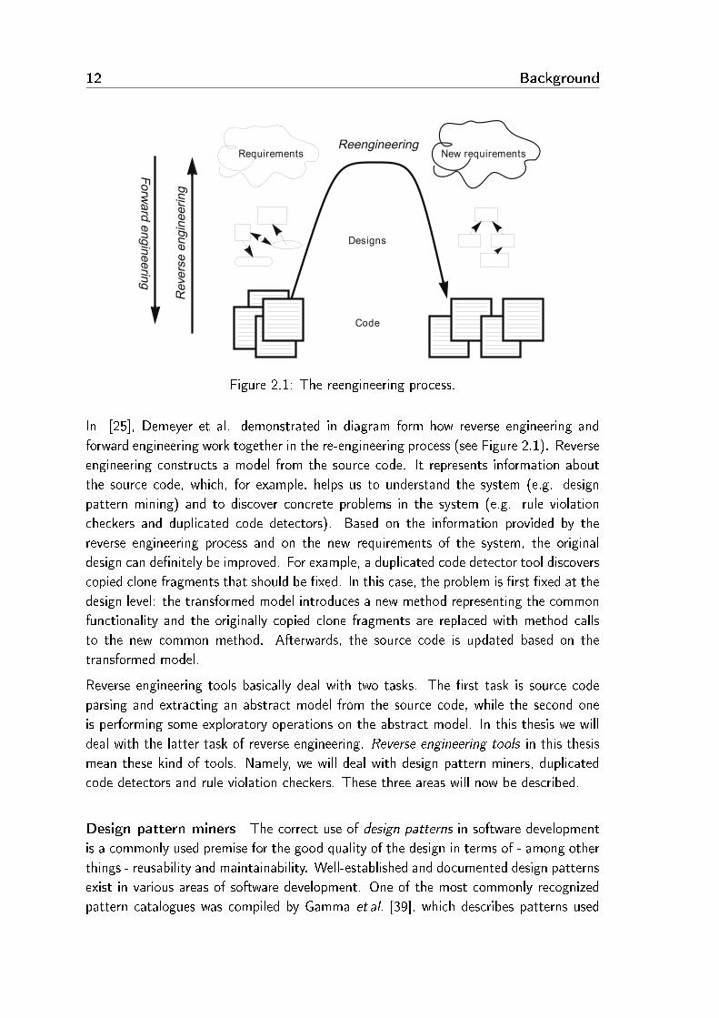
1. Predictor value calculation. In the original pattern mining process [8], Columbusanalyzes the source code and creates an ASG (Abstract Semantic Graph) represen-tation. Afterwards, the design pattern miner component of Columbus (CAN2Dpm)�nds design pattern candidates that conform to the actual DPML (Design PatternMarkup Language) �le, which describes the structure of the pattern looked for.Each design pattern has features that are not related to its structural description.We retrieve this kind of information from the source code and use them as inputfor the learning system. We call these collected values predictors. In this �rststep we calculate predictor values from the ASG and then save them to a CSV �le(predictor table). This �le is basically a table containing the predictor values foreach design pattern candidate.2
2. Manual inspection. Here, we examine the source code manually to decide whetherthe design pattern candidates are instances or false candidates. Then we extendthe predictor table �le with a new column containing the results of the manualinspection.
3. Machine learning. Next, we perform the training of the machine learning systems.The outputs of these systems are model �les which contain the acquired knowledge.
4. Integration. Lastly, we integrate the results of machine learning (the model �les)into Columbus to be able to make smarter decisions by �ltering the design pat-tern candidates. This way, Columbus should report far fewer false positive designpattern candidates to the user.
Figure 3.1 graphically describes this process. The original elements of the design patternmining process of Columbus are denoted by straight lines and empty boxes, while thenew parts introduced by the learning process are denoted by dashed lines and �lled boxes.
2We classify the predictor values according to their magnitude to achieve better learning results. Wedivide the values into equal intervals and use the classes corresponding to these intervals as the inputfor the learning algorithms.
3.2 Predictors 23
Figure 3.1: The learning process
3.2 Predictors
We chose two design patterns out of 16 patterns handled by the matching algorithmfor the experiments. Our �nal choice was the structural pattern Adapter Object andthe behavioural Strategy pattern since these two occurred most frequently in our exper-iments. This choice was also appropriate because, after the manual investigation of thecandidates, we found that there were enough true and false examples as well. More-over, the candidates and their contexts were su�ciently di�erent to train the machinelearning systems successfully. These two patterns are good examples of how general thestructural descriptions of patterns can be in terms of general object-oriented features,and how useful the deeper information can be for their recognition.
In the following we will outline these two design patterns and the predictors that weformulated. We also experimented with other predictors, but these proved to be themost e�ective.

24 Improvement of an existing design pattern miner tool
3.2.1 Adapter object
The aim of the Adapter pattern is to �convert the interface of a class into another
interface that clients expect. Adapter lets classes work together that could not otherwise
because of incompatible interfaces.� [39]
Figure 3.2: The Adapter Object design pattern
The Adapter pattern has four participants (see Figure 3.2). First, the Target classde�nes the domain-speci�c interface that Client uses. Client in turn represents the classcollaborating with objects that conform to the Target interface. Next, the Adaptee classdescribes an existing interface that needs adapting, and lastly Adapter is the class thatadapts the interface of Adaptee to the Target interface.
There are two forms of the Adapter pattern, namely Class and Object. The former usesmultiple inheritance to adapt one interface to another, while the latter uses compositionfor the same purpose. We employed Adapter Object in our experiments.
It may be seen that this structure, the delegation of a request through object composition,is a quite common arrangement used by object-oriented systems and so only a moredetailed analysis may spot the instances of this pattern. Here we identi�ed the followingpredictors for the Adapter Object design pattern:
• A1 � PubAdapteeCalls predictor shows how many public methods of the Adaptercandidate class contain a method call to an Adaptee candidate class. Since themain purpose of the Adapter pattern is to adapt the Adaptee class to the Adapterclass, we reach the Adaptee objects through the Adapter ones. So most publicmethods of an Adapter candidate should contain a method call to an Adapteecandidate.
• A2 � PubAdapteeNotCalls predictor shows how many public methods of theAdapter candidate class do not contain a method call to an Adaptee candidateclass. We assume that the A1 value is greater than A2, because the Adapter'sintent is to adapt the functionality of Adaptee so the Adapter must have morepublic functions that call Adaptee than those that do not.

3.2 Predictors 25
• A3 � NotPubAdapteeNotCalls predictor shows how many non-public methods ofthe Adapter candidate class do not contain calls to an Adaptee candidate. Weassume that if A2 is greater than A1, then the private or protected methods areresponsible for calling the Adaptee. Thus, if A2 is larger than A1, then we assumethat A3 will be a low number because the non-public methods should call theAdaptee.
• A4 � MissingAdapteeParameter predictor shows how many constructors of theAdapter candidate class do not get an Adaptee candidate as a parameter. TheAdapter is likely to get the Adaptee object that it will manage via its constructors,so it should be zero or a low value.
• A5 � AdapteeParameterRatio predictor shows the ratio of the constructors of theAdapter candidate class that get an Adaptee candidate object as a parameter. Weassume that it should be one, or close to one.
• A6 � NewMethods predictor shows how many new methods the Adapter candidateclass de�nes. Client uses Adaptee through the interface of the Target class, sosince the purpose of the Adapter class is to de�ne the methods of Target, no newmethods of its own need to be added.
3.2.2 Strategy
The intent of the Strategy pattern is to �de�ne a family of algorithms, encapsulate each
one, and make them interchangeable. Strategy lets the algorithm vary independently
from clients that use it.� [39]
Figure 3.3: The Strategy design pattern
The Strategy pattern has three participants (see Figure 3.3). The Strategy class declaresan interface common to all supported algorithms. Context uses this interface to call thealgorithm de�ned by a ConcreteStrategy, which implements the algorithm using the

26 Improvement of an existing design pattern miner tool
Strategy interface. The Context class is con�gured with a ConcreteStrategy object andmaintains a reference to a Strategy object.
The fact that the implementation of the algorithm interface is achieved simply by real-izing the Strategy interface with inheritance and method overriding suggests that thispattern also requires a more detailed analysis to distinguish its instances from the falsecandidates. Here we identi�ed the following predictors for the Strategy design pattern:
• S1 � InheritanceContext predictor shows the number of children of the Contextcandidate class. It should be a low value, because otherwise the pattern would bemore similar to the Bridge pattern than to Strategy.
• S2 � IsThereABase predictor shows the number of parents of the Strategy partici-pant. We assume that Strategy does not have any parents because it provides theinterface to change the strategy.
• S3 � Algorithm predictor investigates the ConcreteStrategy candidate classes. Itrepresents a value based on the ConcreteStrategy candidates' algorithmical featureslike the number of loops and recursions. We suppose the more algorithmic featuresit has, the higher the probability of it being a true ConcreteStrategy candidate(instance).
• S4 � ConcreteStrategy predictor shows the number of ConcreteStrategy candidatesdiscovered. If this is very low or one then the main advantage of the Strategypattern will be lost.
• S5 � ContextParam predictor shows the number of methods of the Context can-didate which have a Strategy parameter. Usually the Context class forwards theclient's requests to Strategy so that the client can select the Strategy object atruntime. Thus Context should have at least one method with a Strategy parame-ter.
• S6 � InheritanceStrategy predictor : shows the number of children3 of the Strategycandidate class. This value should be close to S4; but in any case it must besmaller.
3.3 Machine learning approaches used
We employed two machine learning systems for acquiring knowledge from the predictorsets discussed in the previous section. Both systems produce a model that will be usedfor decision making. Besides having the same predictor sets, these two algorithms werealso used in the same way so we were able to test both in the same environment.
3Note that this value is not the same as that for S4 because the ConcreteStrategy-s may be locateddeeper in the class hierarchy, and not all children of Strategy are necessarily ConcreteStrategy-s.
3.4 Results 27
The above represent some of the most popular approaches in the area of machine learn-ing, one being a decision tree and the other a neural network. The system we employedfor the former was C4.5 (which uses an enhanced version of the ID3 algorithm), whilefor the latter it was the Backpropagation algorithm.
C4.5 is an enhanced implementation of the ID3 algorithm that was proposed by Quinlanin 1993 [66]. The C4.5 algorithm makes use of a variant of the rule post-pruningmethod to �nd high precision hypotheses to the target concept of the learning problem.It generates a classi�cation-decision tree for the given data set by recursively partitioningthe data. Training examples are described by attributes (predictor values) whose choicefor a given tree node depends on their information gain at each step during the growthof the tree.
The Backpropagation algorithm [16] works with neural networks that are the meansfor machine learning, whose reasoning concept was borrowed from the workings of thehuman brain. This algorithm uses more layers of neurons; it gets the input patterns andgives them to the input layers. Then it computes the output layer (the output decision)from the input layer and the hidden (inner) layers. In addition, an error value is alsocalculated based on the di�erence between the output layer and the target output pattern(the learning data). The error value is propagated backwards through the network, andthe values of the connections between the layers are adjusted in such a way that thenext time the output layer is computed the result will be closer to the target outputpattern. This method is repeated until the output layer and target output pattern arealmost equal or up to some iteration limit.
3.4 Results
Here we will present the results of our experiments concerning the accuracy of thelearning methods and their e�ect on design pattern recognition.
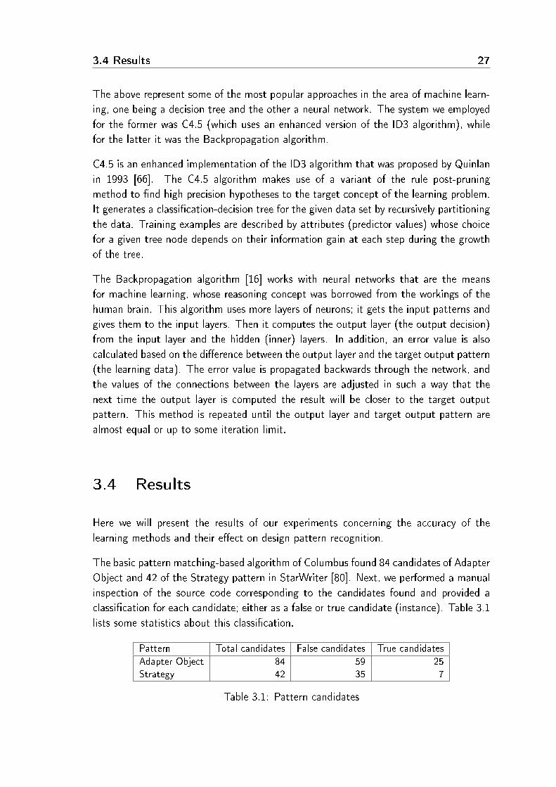
The basic pattern matching-based algorithm of Columbus found 84 candidates of AdapterObject and 42 of the Strategy pattern in StarWriter [80]. Next, we performed a manualinspection of the source code corresponding to the candidates found and provided aclassi�cation for each candidate; either as a false or true candidate (instance). Table 3.1lists some statistics about this classi�cation.
Pattern Total candidates False candidates True candidates
Adapter Object 84 59 25Strategy 42 35 7
Table 3.1: Pattern candidates

28 Improvement of an existing design pattern miner tool
This manually tagged list of candidates was then used as the training set for the learningsystems together with the calculated predictor values for each candidate, as describedin Section 3.1.
In the following we will �rst overview our experiences with the investigation of thecandidates and their relation to the actual predictor values, and then we will present ourresults concerning the learning e�ciency.
3.4.1 Adapter object candidates investigation
During our investigation of the Adapter Object candidates we found that they can bedivided into groups that share some common features. We will present two examples ofthese groups.
Candidates belonging to the �rst group all have an Adapter class that references anotherclass through a data member of a pointer type. The referenced class is, however, toosimple to be considered as an Adaptee as it has very few members or too few methodsof it are used by the Adapter. For example, the Adapter contains a String (which is theAdaptee) that holds the name of the current object, and one of the Adapter's methodsneeds the length of the String so it calls the corresponding method of String. Clearly,these candidates are not real Adapter Object patterns.
Candidates of the second group have an Adapter class that implements some kind ofcollection data structure like a set, list or an iterator. These code fragments also have thestructure of an Adapter Object design pattern, but their purpose is obviously di�erent,so they are not real patterns either.
After we had classi�ed the candidates as true (instance) or false candidates and thepredictor values had been calculated, we investigated whether the actual predictor valuessupport our assumptions about the predictors given in Section 3.2. Table 3.2 shows thepredictor values for some typical candidates along with their manual classi�cation results.
Candidates C1 C2 C3 C4
A1 - PubAdapteeCalls 5 1 0 2A2 - PubAdapteeNotCalls 4 0 35 14A3 - NotPubAdapteeNotCalls 0 2 11 52A4 - MissingAdapteeParameter 0 0 4 2A5 - AdapteeParameterRatio 1 1 0.33 0A6 - NewMethods 7 1 26 9
Classi�cation (True/False) T T F F
Table 3.2: Some predictor values for Adapter Object
Let us look at, say, the C1 candidate, which is a real pattern instance. We can see thatmore public methods in Adapter call the Adaptee (A1>A2), while there are no non-public

3.4 Results 29
methods that do not call it (A3=0). The values of A4, A5 and A6 also support ourassumptions (all Adapter constructors take an Adaptee). Let us take the C3 candidate,which is a false candidate, as another example. It can be seen that the relations betweenthe values of A1, A2 and A3 are exactly the opposite of the true example, i. e. thereare few calls from Adapter to Adaptee. A5 and A6 support our assumptions as well.Based on this, we may safely assume that the learning methods probably discoveredthese relationships as well.
3.4.2 Strategy candidates investigation
First, we will overview some interesting Strategy candidates. There was a class calledSwModify, which behaved as Context, while SwClient assumed the role of Strategy.The former had a method called Modify that would call the Modify method of thelatter. Inherited (direct or indirect) classes of SwClient de�ned di�erent Modify methods,so we classi�ed this candidate as an instance. We also noticed that the number ofConcreteStrategy-s was quite high.
The above-mentioned Strategy class called SwClient appeared in another candidate tooas the Strategy class, which we eventually treated as a false one for the followingreasons. Context was represented by the class SwClientIter that communicated withSwClient through the AlgorithmInterface method called IsA. ConcreteStrategy-s de�nedthis method, but since its purpose was only RTTI (runtime type identi�cation) and notthat of a real algorithm, we classi�ed this candidate as false.
There were also some candidates with only one ConcreteStrategy. We decided to classifythese as false candidates because, after investigating all other instances, it was obviousthat a real Strategy pattern instance should have several ConcreteStrategy-s otherwiseits initial purpose is lost.
We investigated the predictor values together with the classi�cations of Strategy in moredepth in order to verify our initial assumptions about the predictors. Table 3.3 showsfour example candidates with the predictor values and the classi�cations.
Candidate C1 C2 C3 C4
S1 - InheritanceContext 0 0 3 1S2 - IsThereABase 0 1 3 1S3 - Algorithm 10.15 13.6 0 0S4 - ConcreteStrategy 65 10 1 2S5 - ContextParam 2 1 2 6S6 - InheritanceStrategy 57 9 2 35
Classi�cation (True/False) T T F F
Table 3.3: Some predictor values for Strategy

30 Improvement of an existing design pattern miner tool
The C1 candidate is classi�ed as an instance (true positive). It can be clearly seen thatthe S1 and S2 predictors are low, while S3 and S4 are high, as expected. Predictor S5 isgreater than 0 and S6 is smaller than S4, so this appears to be a true positive candidate.
C4 is a false candidate, where the S1 and S2 predictors are not zero. Furthermore S3and S4 are very low, which suggests that this should be a false candidate according toour above assumptions. Lastly, S6 is also much higher than S4, which further supportsthe belief that this is a false candidate. The manual classi�cation of it was false, so ourassumptions about the predictors were again correct.
In the next section, where we present the actual results of the learning e�ciency, we willsee that the learning methods successfully discovered these features of the predictorsand incorporated them into their models.
3.4.3 Learning e�ciency
To assess the accuracy of the learning process we applied the method of three-fold cross-validation,4 which means that we divided the predictor table �le into three equal partsand performed the learning process three times. Each time we chose a di�erent partfor testing and the other two parts for learning. We de�ne the following basic measuresthat are required to assess the learning e�ciency5:
• True Positives of Learning (TPL): an instance correctly classi�ed by the machinelearning model as a true candidate (aka instance).
• False Positives of Learning (FPL): a false pattern candidate incorrectly classi�ed
by the machine learning model as a true candidate (aka instance).
• True Negatives of Learning (TNL): a false pattern candidate correctly classi�ed bythe machine learning model as a false pattern candidate.
• False Negatives of Learning (FNL): an instance incorrectly classi�ed by the machinelearning model as a false candidate.
We measured the learning accuracy score in each case as the ratio of the number ofcorrect decisions of the learning systems (compared to the manual classi�cation) overthe total number of candidates i.e. ( TPL+TNL
TPL+TNL+FPL+FNL)×100. We also calculated the
average and standard deviation (shown in parentheses) using these three testing resultsand got the scores shown in Table 3.4.
It can be seen that the two learning methods produced very similar results, but theaccuracy score was worse in the case of Adapter Object. This is probably due to two
4We did not have enough design pattern candidates to perform the usual ten-fold cross-validationmethod, so we divided the training set into three parts instead of ten.
5These measures should not be confused with those de�ned in Section 2.2.

3.4 Results 31
Design Pattern Decision Tree Neural network
Adapter Object 66.70% (21.79%) 66.70% (23.22%)Strategy 90.47% ( 4.13 %) 95.24% ( 4.12 %)
Table 3.4: Average accuracy with standard deviation based on three-fold cross validation
reasons. First, one of the three validation tests produced very bad results, which worsenedthe overall percentage scores, and second, it seems that we found better predictors forStrategy than for Adapter Object.
However, the real importance of the learning accuracy scores will be appreciated onlyby investigating in more detail how the application of machine learning improves theaccuracy of the design pattern recognition. To do this, we applied the following measures:
• Speci�city (SPC) This measures how the learning model can �lter out falsecandidates: TNL
TNL+FPL× 100
• Negative Predictive Value (NPV) This shows to what extent the predictionof false candidates was wrong: TNL
TNL+FNL× 100
• Recall (R) This measures how many of the manually classi�ed true positivecandidates (instances) are correctly classi�ed by the learning method: TPL
TPL+FNL×
100.
• Precision (P) This shows the degree of correctly classi�ed true positive candi-dates (instances): TPL
TPL+FPL× 100
Algorithm Neural Network Decision Tree
Pattern Adapter Object Strategy Adapter Object Strategy
TPL 6 7 5 5FPL 9 2 8 2TNL 50 33 51 33FNL 19 0 20 2
Speci�city 84.75% 94.29% 86.44% 94.29%Negative Pred. Val. 72.46% 100% 71.83% 94.29%Recall 24% 100% 20% 71.43%Precision 40% 77.78% 38.46% 71.43%
Table 3.5: Learning statistics
Table 3.5 shows the results obtained for these measures for each learning method. It maybe concluded from the table that speci�city is really good with both learning methodsand design patterns (85�94%), and that few true candidates (instances) were wronglypredicted as false ones, so the NPV of �ltering is also quite good.
As for the ability to predict true positive candidates (instances), the results are diverse.Strategy candidates were fairly well classi�ed, but only one fourth to one �fth of AdapterObject instances were found by the learning methods with a modest precision score. Thismay be accounted for by the fact that the predictors were designed with the intent to�lter out false pattern candidates (Speci�city).
32 Improvement of an existing design pattern miner tool
3.5 Summary
In this chapter we presented an approach whereby signi�cant improvements in accuracycan be achieved in design pattern recognition compared to the conventional structurematching-based methods. The main idea here was to employ machine learning methodsin order to re�ne the results of the structure-based approaches.
Our goal was to �lter out false candidates from the results provided by our structure-based pattern miner algorithm [8]. In our experiments we achieved learning accuracyscores of 67�95% and with the model obtained we were able to �lter out 51 of the 59false candidates of the Adapter Object design pattern (out of a total of 84 candidates)and 33 of the 35 false candidates of the Strategy pattern (out of a total of 42 candidates).
The method presented here has a critical part. The manual evaluation of design patterncandidates, which are discovered by a certain tool, is a really time-consuming, dull andtaxing task. The person who carries out the assessment has to look for the appropriatesource �le(s) and locate the appropriate source code fragment(s), and then investigatethe fragments together to get the whole picture. Afterwards, he has to record his opinionsfor later use. However, this part is really important in our procedure, so tool-supportfor this would be really useful. Among other things and based on this motivation, wedeveloped DEEBEE, an online framework and benchmark that is capable of evaluatingand comparing design pattern candidates. DEEBEE will be presented later in Chapter 5.

Part II
Evaluation of design pattern miner
tools
33


Chapter 4
Performance evaluation of design
pattern miner tools
�The only source of knowledge is experience.�
Albert Einstein
The purpose of this chapter is to compare three design pattern miner tools, namelyColumbus, Maisa and CrocoPat. We chose these tools because it is possible to preparea common input for them with Columbus, our front end. Our study was based on thesame input data, hence ensuring a fair-minded comparison, because any parsing errorsa�ected all three tools in the same way. The tools were compared with three views inmind: di�erences between the candidates, speed and memory requirements. We did notanalyze whether a design pattern candidate was true or false; we examined these toolsonly from the viewpoint of structural candidates and di�erences.
From the results of experiments we found that CrocoPat is generally the fastest, Maisaneeds the least memory and Columbus is the fastest in the case of mining very complexpatterns.
4.1 Framework
Our previous work enabled us to provide the input for Maisa [34], while in the case ofCrocoPat we created a new plug-in for Columbus which is able to prepare the appropriateinput. We illustrate this process in Figure 4.1.
4.1.1 CrocoPat
Beyer et. al. [14, 15] developed a system that is able to work with large graphs e�ectively.The e�ectiveness of the system is based on binary decision diagrams which represent therelations compactly. They developed the relation manipulation language (RML) for
35

36 Performance evaluation of design pattern miner tools
Figure 4.1: Common framework
manipulating n-ary relations and a tool implementation called CrocoPat. CrocoPat isan interpreter, and it executes RML programs. First, CrocoPat reads the input graph inRigi Standard Format (RSF) [59] from the standard input. Afterwards, CrocoPat readsthe RML description and creates a BDD representation from it. After, an RSF outputis produced that shows the patterns found in the input graph according to the givenRML description. We extended the Columbus framework with a plugin that generatesthe appropriate input graph for CrocoPat based on the information in the ASG1.
The RML (Relational Manipulation Language) is very similar to logic programming lan-guages like Prolog, but it contains techniques of imperative programming languages too.Hence, it is very expressive and it can describe design patterns among other structures.Unfortunately, we have not found any design pattern library in RML, so we created thedescriptions of the patterns in the RML language for 18 design patterns. Figure 4.2 showsone concrete implementation of these, namely the description of the Factory Methoddesign pattern in CrocoPat's RML language.
4.2 A comparative approach
Now we will present a comparative approach of the given design pattern mining toolswith the following viewpoints:
• Di�erences between the design pattern candidates found. In a fair comparisonof the tools we have to know and take into consideration why their results aredi�erent. However, the di�erences might be due to several reasons. The di�erenttools might use di�erent techniques to de�ne a design pattern. Most of the timethe recognition algorithms are di�erent as well. Furthermore, the representation of
1The Columbus framework was introduced in Section 2.3.

4.2 A comparative approach 37
AbstractClass(X) := CLASS(X) & ABSTRACT(X);
Product(X) := AbstractClass(X);
ConcreteProduct(Cpr,Pr) := CLASS(Cpr) & Product(Pr) &
TC(INHERITANCE(Cpr,Pr));
Creator(Cr,Pr) := AbstractClass(Cr) & ASSOCIATION(Cr,Pr) & Product(Pr) &
Cr != Pr;
CreatMethods(Cr,Pr,M) := Creator(Cr,Pr) & HASMETHOD(Cr,M);
CreatorFM(Cr,Pr,FM) := CreatMethods(Cr,Pr,FM) & VIRTUAL(FM) &
PUREVIRTUAL(FM) & RETURNS(FM,Pr);
CreatorAM(Cr,Pr,AM,FM) := CreatMethods(Cr,Pr,AM) &
CreatorFM(Cr,Pr,FM) & CALLS(AM,FM);
ConcreteCreator(Ccr,Pr,Cr,Cpr) := CLASS(Ccr) & ASSOCIATION(Ccr,Pr) &
Product(Pr) & Creator(Cr,Pr) & TC(INHERITANCE(Ccr,Cr)) &
ConcreteProduct(Cpr,Pr) & Ccr != Pr;
CCreatorFM(Ccr,Pr,Cpr,M) := ConcreteCreator(Ccr,Pr,_,Cpr) &
HASMETHOD(Ccr,M) & VIRTUAL(M) & !PUREVIRTUAL(M) &
RETURNS(M,Pr) & CREATES(M,Cpr);
FactoryMethod(Prod,Creat,CProd,CCreat,CreatFM,CreatAM,CcreatFM) :=
Product(Prod) &
Creator(Creat,Prod) &
ConcreteProduct(CProd,Prod) &
ConcreteCreator(CCreat,Prod,Creat,CProd) &
CreatorFM(Creat,Prod,CreatFM) &
CreatorAM(Creat,Prod,CreatAM,CreatFM) &
CCreatorFM(CCreat,Prod,CProd,CcreatFM) &
CProd != CCreat &
Creat != CProd;
Figure 4.2: Factory Method pattern in RML
the results might not be the same. Based on this viewpoint, we will try to discoverthe possible reasons for the di�erences, and to test our current assumptions.
• Speed. Design pattern mining can be a very time consuming task, e.g. becauseof the cost of a conventional graph matching algorithm. Hence we shall comparethe given tools in terms of speed as well. Speed is measured by the amount of thetime taken by the tool to mine the given design pattern in the given C++ project.

38 Performance evaluation of design pattern miner tools
Section 4.3.2 describes how the speed of the given tools is measured.
• Memory usage. Similar to the previous viewpoint, memory usage could be aproblematic point of a design pattern miner tool. We measured the maximalmemory required for the design pattern mining task. It was not straightforwardbecause the memory usage of CrocoPat is �xed, and only the Columbus sourcecode was available. The memory measuring method applied for the given tools isdescribed in Section 4.3.3.
4.3 Results
We made a comparison on four open source small-to-huge systems, to make the bench-mark results independent of system characteristics like size, complexity and applicationdomain. These four real-life, freely available C++ projects are the following.
• DC++ 0.687. An open-source client for the Direct Connect Protocol that allowsone to share �les over the Internet with other users [24].
• WinMerge 2.4.6. An open-source visual text �le di�erentiating and merging toolfor Win32 platforms [93].
• Jikes 1.22-1. A compiler that translates Java source �les (as de�ned in The JavaLanguage Speci�cation) into the byte-coded instruction set and binary formatde�ned in The Java Virtual Machine Speci�cation [47].
• Mozilla 1.7.12. All-in-one open source Internet application suite [58]. We used acheckout dated March 12, 2006.
Table 4.1 lists some statistics about the projects we analyzed. The �rst row shows howmany source and header �les were analyzed in the evaluated software systems. Thesecond row lists the size of these source and header �les in megabytes.
Size info. DC++ WinMerge Jikes Mozilla
No. of �les 338 512 74 11,325Size (MB) 3 5.3 3 127LOC 12,727 49,809 52,169 1,288,869No. of classes 68 174 258 5,467
Table 4.1: About the size of each project studied
The last two rows were calculated via the metric plug-in of Columbus, and gives infor-mation about the total lines of code (LOC) and the number of classes. By LOC wemean every line in source code that is not empty and is not a comment line (also knownas �logical lines of code�).

4.3 Results 39
All the tests were run on the same computer, so the measured values were independentof the hardware and hence the results are comparable. Our test computer had a 3GHz Intel Xeon processor with 3 GB memory. In the next section we will describe ourbenchmark results and then analyze them in detail.
Now we will present our results concerning the di�erences between the design patterncandidates found, the running-time and the memory requirements. Below we will beginwith the discovered pattern candidates, and then compare the time requirements for thetools. After, we will list the memory requirements of the design pattern mining tools.
4.3.1 Discovered pattern candidates
In this section we will describe our experiments related to pattern candidates found bythe design pattern miner tools that we compared. Unfortunately, Maisa did not containdescriptions of the patterns Bridge, Chain of Responsibility, Decorator, State, Strategyand Template Method (the results for these are marked with dashes in our tables).We examined the di�erences between the tools manually, checking and comparing thecandidates and the description of design patterns. First, we summarize our results onDC++ in Table 4.2.
Design Pattern Columbus Maisa CrocoPat
Abstract Factory 0 0 0Adapter Class 0 2 0Adapter Object 0 0 0Bridge 0 - 0Builder 0 0 0Chain Of Responsibility 0 - 0Decorator 0 - 0Factory Method 0 0 0Iterator 0 0 0Mediator 0 0 0Prototype 0 0 0Proxy 0 0 0Singleton 0 0 0State 14 - 14Strategy 14 - 14Template Method 0 - 0Visitor 0 0 0
Table 4.2: DC++ candidates
This was a small software package, so it did not contain too many design patterncandidates. Maisa found two Adapter Classes, while CrocoPat and Columbus foundnone. This is due to the fact that the de�nition of the Adapter Class in Maisa di�ered

40 Performance evaluation of design pattern miner tools
from those in Columbus and CrocoPat. In Maisa, the Target participant class was notabstract and the Request method of the Target class was not pure virtual, while inColumbus and CrocoPat these features were requested. We examined the two AdapterClass candidates in Maisa, and we found that the Targets were not abstract in these casesand the Request operations were not pure virtual. Columbus and CrocoPat found 14State and 14 Strategy design pattern candidates. The reason for the identical numberof candidates is that the State and Strategy patterns have the same static structure, sotheir description in the tools were the same as well [8].
Table 4.3 shows the results of using the tools in the case of WinMerge. Maisa foundtwo more Adapter Objects in WinMerge than Columbus. In the �rst case the di�erencewas due to the fact that the Request method of a participant Adapter Object class wasde�ned virtual in Columbus, while Maisa did not have this precondition. In the secondcase the pattern found in Maisa had a Target participant that was not abstract, whichwas a requirement in Columbus. When we relaxed the description of this pattern inColumbus, it found these two candidates too. The best solution would be if an exactde�nition existed for this pattern in both tools. CrocoPat found six Adapter Objectcandidates, while Columbus found only three.
Design Pattern Columbus Maisa CrocoPat
Abstract Factory 0 0 0Adapter Class 0 0 0Adapter Object 3 5 6Bridge 0 - 0Builder 0 1 0Chain Of Responsibility 0 - 0Decorator 0 - 0Factory Method 0 0 0Iterator 0 0 0Mediator 0 0 0Prototype 0 0 0Proxy 0 0 0Singleton 0 0 0State 3 - 10Strategy 3 - 10Template Method 2 - 42Visitor 0 0 0
Table 4.3: WinMerge candidates
The reason was that when Columbus found pattern candidates with certain participantclasses in common, then Columbus treated them as the same pattern candidate. Forexample, if a design pattern (e.g. Strategy) contains a class with child classes (wherethese child classes could be of arbitrary number) then every repeated child class (e.g.ConcreteStrategy-s) and every repeated method (e.g. repeated AlgorithmInterface meth-ods in each ConcreteStrategy) appears as a new candidate in the case of CrocoPat, while

4.3 Results 41
Columbus grouped these candidates into one big candidate based on the common (e.g.Strategy) class. This is a very important di�erence between Columbus and CrocoPat,so we will stress this di�erence several times.
Maisa found a Builder in WinMerge but the two other tools did not, because in Maisathe Builder pattern representation did not contain the Director participant while theother two tools contained it. In the case of State, Strategy and Template Method thedi�erences were because Columbus counted pattern candidates participating with certainclasses in common only once, as in the case of Adapter Object.
Next, we will describe our experiments on design pattern candidates found in Jikes (seeTable 4.4). Maisa found an Adapter Class, while Columbus and CrocoPat did not.The reason was the same as in the case of DC++, namely that in Maisa the Targetparticipant class was not abstract and the Request method of the Target class was notpure virtual, but in Columbus and CrocoPat these features were required. In the case ofAdapter Object Maisa failed to �nd a lot of candidates, while Columbus and CrocoPatdiscovered a lot of design pattern candidates. It appeared as if CrocoPat found morecandidates because Columbus counted repeated pattern candidates with certain classesin common only once. In actual fact, these tools found the same pattern candidates.
Design Pattern Columbus Maisa CrocoPat
Abstract Factory 0 0 0Adapter Class 0 1 0Adapter Object 78 10 94Bridge 0 - 0Builder 0 1 0Chain Of Responsibility 0 - 0Decorator 0 - 0Factory Method 0 0 0Iterator 0 0 0Mediator 0 4 0Prototype 84 0 84Proxy 53 74 66Singleton 0 0 0State 170 - 334Strategy 170 - 334Template Method 4 - 4Visitor 0 23 0
Table 4.4: Jikes candidates
In Maisa, the Builder pattern representation did not contain the Director participant,so Maisa found an incomplete Builder candidate in Jikes. CrocoPat did not �nd anyMediator in Jikes, while Maisa found four. This is because Maisa described Mediator ina very special way, so that it contained a Mediator with two Colleagues, but ConcreteMediators were overlooked. The description of Mediator in CrocoPat required a Mediator

42 Performance evaluation of design pattern miner tools
abstract class with a child ConcreteMediator class as well. In the case of Proxy, eachtool discovered the same 53 candidates, but CrocoPat also counted repeating patternswith di�erent methods and classes in 13 cases (66 altogether). Maisa found 21 morecandidates more (74 altogether) because it did not need an abstract Proxy participantclass in the Proxy design pattern. In the case of State and Strategy, it seems thatColumbus found fewer design pattern candidates, but it counted each repeated patternwith certain classes in common only once. Maisa found 23 Visitor patterns which theother two did not. This is due to the permissive description of this pattern in Maisa.
Design Pattern Columbus Maisa CrocoPat
Abstract Factory 5 1 9Adapter Class 0 59 0Adapter Object 65 57 247Bridge 880 - 1100Builder 0 11 0Factory Method 0 67 0Mediator 0 2 0Prototype 83 25 901Proxy 0 1 0Singleton 8 0 20State 722 - 7662Strategy 722 - 7662Template Method 279 - 522Visitor 0 30 0
Table 4.5: Mozilla candidates
Table 4.5 shows the results of our experiments with Mozilla. A lot of design patterncandidates were found, as in the case of State, where CrocoPat found 7662 and Columbusdiscovered 722 candidates. This huge di�erence was due to the fact that the designpattern candidates found were not grouped by CrocoPat, while Columbus grouped them.In the case of Adapter Class, the reasons for the di�erences were the same as in Jikes andin DC++ examined earlier. Columbus did not count repeated candidates in the caseof Adapter Object, so it actually found the same candidates as CrocoPat, but Maisamissed some because of its di�erent pattern description. CrocoPat and Columbus foundthe same candidates of the Bridge pattern, but Columbus counted the candidates withcertain classes in common only once. Maisa found incomplete Builder candidates again,because the description of this pattern did not contain the Director participant class.Maisa found Factory Method candidates, while the other two did not. This is becausethe other two de�ned Factory Method with an abstract Product and an abstract Creatorparticipant class, while Maisa did not require these participants to be abstract. CrocoPatdid not �nd any Mediator candidate in Mozilla, but Maisa discovered two candidates.This is because Maisa described Mediator in a very special way, so it contained a Mediatorwith two Colleagues, but Concrete Mediators were missing. In the case of Prototype,

4.3 Results 43
Singleton, State, Strategy and Template Method the di�erences were again due to thefact that CrocoPat counted each repeated pattern candidate, while Columbus countedthese repeated ones with certain classes in common only once.
We have not explained every discrepancy, but we o�ered some of the more commonreasons for each. In essence, the design pattern candidates found would be the same inmost of the cases if we could disregard the following common causes of the di�erences:
• Di�erent de�nitions of design patterns. We found that there were some speci�creasons why the tools discovered di�erent pattern candidates. The main one wasthat in some cases a design pattern description overlooked a participant as in thecase of the Builder pattern in Maisa. Here the pattern de�nition did not containthe director participant, hence the candidates discovered by Maisa were not thesame as those found by the other two. For example, the results of Maisa inWinMerge for the Builder pattern di�ered from those of CrocoPat and Columbusfor just this reason.
• Precision of pattern descriptions. Another di�erence was how precise and strictthe pattern descriptions were. For example, in the case of Jikes the di�erences inthe numbers of Adapter Class candidates found were due to the fact that CrocoPatand Columbus de�ned the Target as abstract while Maisa did not.
• Di�erences in algorithms. We found di�erences in the design pattern miner algo-rithms as well. Columbus and Maisa counted the repeated candidates with certainclasses in common only once, but CrocoPat counted each occurrence.
The di�erences between the tools can be summarized in two points:
• Intentional feature is integrated into the tool to achieve better results. Thesefeatures should not be modi�ed in a comparison. For example, in Maisa the missingparticipant could be an intentional feature to discover more pattern instances.
• The ad-hoc nature of the tools creates unnecessary and confusing di�erences.These features should be standardized so as to have a common form or solutionto facilitate a comparison. For example, in Maisa the missing participant mightbe ad-hoc as well.
The connection between above-mentioned di�erences and the intentional or ad-hoc fea-tures is the following. Di�erences caused by di�erent de�nitions of design patterns couldbe intentional and ad-hoc as well. In this way, it is hard to determine whether it wasad-hoc or intentional. Hence it would be di�cult to standardize and to eliminate thisdi�erence among the tools. However, based on our experiments it would be useful tohave some kind of common design pattern de�nition repository, which would be worthstudying. Di�erences caused by precision of pattern descriptions are quite similar to theprevious one, and they arise for the same reasons.

44 Performance evaluation of design pattern miner tools
Lastly, certain kinds of di�erences in algorithms could be standardized in a comparisonof design pattern miner tools. For example, Columbus and Maisa counted the repeatedcandidates with certain classes in common only once while CrocoPat counted each oc-currence. This di�erence should be handled and standardized in a fair comparison ofcandidate correctness. In chapters 5 and 7 a grouping method will be presented thatcan handle this di�erence.
4.3.2 Pattern mining speed
Now we will compare the speed of the three design pattern miner tools. We wanted tomeasure just the search time for patterns, hence we divided the running time into twoparts, namely an initialization part and a pattern mining part.
Subject system Columbus Maisa CrocoPat
DC++ 00:00:03 00:00:00 00:00:03WinMerge 00:00:08 00:00:03 00:00:11Jikes 00:00:11 00:00:06 00:00:12Mozilla 00:05:33 00:01:32 00:03:12
Table 4.6: Initialization times
Table 4.6 contains the initialization time of the tools (hh:mm:ss). For Maisa and Croco-Pat we also measure the time required for exporting from the ASG representation intothe tool-speci�c format (see Table 4.7).
Exporter Name CAN2Maisa CAN2CrocoPat
DC++ 00:00:06 00:00:05WinMerge 00:01:05 00:00:13Jikes 00:00:13 00:00:10Mozilla 00:06:11 00:05:47
Table 4.7: Initialization time - exporters
Tables 4.8, 4.9 and 4.10 only contain the pattern mining times. These times weremeasured in the following way:
• Columbus. We extended Columbus to report time statistics for the pattern miningprocedure. We only considered the graph matching time; we did not include thetime taken for ASG to load.
• CrocoPat. For CrocoPat, we made a small tool which executed CrocoPat andmeasured its running time. We measured the time needed for each pattern miningprocedure for each subject software system. Next, we also measured the timefor the subject systems with an empty RML program, because this way we could

4.3 Results 45
measure the time necessary to reserve the memory and to prepare the BDD rep-resentation (initialization time). After, we subtracted the initialization time fromthe full running time for each result, and this way obtained the pattern matchingtimes.
• Maisa. Maisa created statistics for each pattern mining procedure, which containedinformation about the time necessary for pattern mining and for the initialization,so we used these generated statistics.
First, we will list our results for DC++. In this case the required time was very small foreach assessed pattern miner tool (lower than one second), hence they can be treated asbeing practically identical. This is due to the small size of the DC++ system, hence thedesign pattern candidates were discovered very quickly in this system by all three tools.
Design Pattern Columbus Maisa CrocoPat
Abstract Factory 00:00:00 00:00:02 00:00:07Adapter Class 00:00:00 00:00:00 00:00:07Adapter Object 00:00:00 00:00:17 00:00:08Bridge 00:00:00 - 00:00:08Builder 00:00:00 00:00:24 00:00:09Chain Of Responsibility 00:00:00 - 00:00:08Decorator 00:00:00 - 00:00:09Factory Method 00:00:00 00:00:02 00:00:01Iterator 00:00:00 00:00:21 00:00:01Mediator 00:00:00 00:00:24 00:00:04Prototype 00:00:00 00:00:02 00:00:08Proxy 00:00:00 00:00:22 00:00:14Singleton 00:00:00 00:00:00 00:00:07State 00:00:03 - 00:00:08Strategy 00:00:03 - 00:00:08Template Method 00:00:01 - 00:00:06Visitor 00:00:00 00:00:00 00:00:05
Table 4.8: WinMerge times
In the case of WinMerge (see Table 4.8), Columbus was the best tool. This is due tothe fact that the Columbus design pattern mining algorithm �lters out several classes atthe beginning of the process and WinMerge has a relatively small number of classes. Incontrast, with Jikes and Mozilla, Columbus could not �lter out as many classes at thebeginning of the process so it achieved worse results than those of the other two.
The time requirements for discovering patterns in Jikes is shown on Table 4.9. Columbuswas very fast in the case of larger patterns (e.g. Abstract Factory, Visitor), because itcould �lter out [8] a lot of class candidates at the beginning of the discovering process.However, Columbus was slower in the case of smaller patterns (e.g. Template Method)because here a lot of class candidates remained for the detailed discovery process. Thetime requirements for CrocoPat and Maisa were rather similar.

46 Performance evaluation of design pattern miner tools
Design Pattern Columbus Maisa CrocoPat
Abstract Factory 00:00:00 00:00:06 00:00:09Adapter Class 00:00:00 00:00:04 00:00:07Adapter Object 00:00:09 00:00:11 00:00:07Bridge 00:00:00 - 00:00:06Builder 00:00:08 00:00:59 00:00:07Chain Of Responsibility 00:00:00 - 00:00:07Decorator 00:00:00 - 00:00:18Factory Method 00:00:00 00:00:04 00:00:02Iterator 00:00:00 00:00:55 00:00:07Mediator 00:00:00 00:01:05 00:00:12Prototype 00:04:18 00:00:04 00:00:07Proxy 00:00:00 00:01:03 00:00:13Singleton 00:00:00 00:00:00 00:00:11State 00:04:48 - 00:00:12Strategy 00:04:48 - 00:00:12Template Method 00:03:55 - 00:00:06Visitor 00:00:00 00:00:06 00:00:14
Table 4.9: Jikes times
Design Pattern Columbus Maisa CrocoPat
Abstract Factory 00:02:32 00:18:21 00:13:43Adapter Class 00:00:06 00:18:34 00:14:34Adapter Object 00:04:41 03:07:03 00:13:42Bridge 04:50:29 - 00:17:20Builder 01:39:09 04:09:22 00:14:02Chain Of Responsibility 00:00:07 - 00:13:33Decorator 00:00:18 - 00:27:40Factory Method 00:03:03 00:15:56 00:00:02Iterator 00:00:07 03:54:12 00:14:19Mediator 00:48:03 04:19:07 00:18:10Prototype 01:24:55 00:14:21 00:25:49Proxy 00:00:07 04:41:47 00:27:10Singleton 00:00:02 00:00:00 00:13:17State 04:09:20 - 00:20:22Strategy 04:09:20 - 00:20:22Template Method 00:14:46 - 00:13:27Visitor 00:00:07 00:06:56 00:20:45
Table 4.10: Mozilla times
Table 4.10 lists our results for Mozilla. In most cases, CrocoPat produced the bestresults, but in certain cases Columbus and Maisa were faster. Columbus was slow whenit was only able to �lter out a small number of class candidates at the beginning of thediscovery process. The CSP algorithm of Maisa was also slow here.
Overall, we concluded that the best tool from a speed perspective is CrocoPat, but in

4.3 Results 47
some cases Columbus was faster. Columbus can be applied in the case of small- ormedium-sized systems and in the case of complex design patterns like Visitor. As forCrocoPat, it can used in the case of a larger system or in the case of a simpler designpattern like Template Method.
4.3.3 Memory requirements
Now we will compare the memory usage of the three design pattern miner tools. Wemeasured the memory requirements of each design pattern mining procedure, but wewill summarize our results in one table because we found them to be very similar.
The memory measurement method for the three systems was carried out in the followingway:
• Columbus. We extended the tool at the source code level so that it reported dataabout its memory usage automatically.
• Maisa. Maisa did not report its memory usage, so we measured it by simplymonitoring its peak memory usage on the task manager.
• CrocoPat. CrocoPat's memory usage is constant and can be set as a com-mand line parameter. Therefore, we executed CrocoPat between 1 megabyte to200 megabytes of reserved memory for each pattern mining process (it is based ona binary search algorithm). After, we took the smallest case where CrocoPat stillterminated normally.
The results here showed that the memory usage strongly depends on the size of theprojects analyzed and it is independent of the given design patterns. This is true foreach pattern miner tool, as can be seen in Table 4.11.
Subject system Columbus Maisa CrocoPat
DC++ 37 (19) 10-11 2-3WinMerge 71 (32) 13-14 10-11Jikes 51 (26) 13-17 10-14Mozilla 866 (330) 60-71 125-175
Average 256 (102) 24-28 37-51
Table 4.11: Memory requirements in megabytes
In the case of Columbus, the required memory was very large compared to the othertwo. This is due to the fact that Columbus is a general reverse engineering frameworkand design pattern detection is just one of its many features. For this reason it uses anASG representation, which contains all the information about the source code (includingdetailed facts about statements and expressions not needed for design pattern detection)

48 Performance evaluation of design pattern miner tools
for all kinds of tasks. Right now, for technical reasons, the design pattern miner plug-in of Columbus does not work without the ASG (although it does not need it), but wewould like to �x this problem. Hence, we also measured the memory needed by Columbuswithout the ASG and listed these values in parentheses in Table 4.11.
Note that with CrocoPat and Maisa the required memory was smaller because their inputsonly contained information about the source code necessary for pattern detection.
After viewing Table 4.11 we may conclude that, in the terms of memory requirements,Maisa's performance was the best.
4.4 Summary
In this chapter we compared three pattern miner tools, namely Columbus, Maisa andCrocoPat. We compared them in terms of di�erences of pattern candidates, speedand memory consumption. We provided a common input for the tools by analyzingthe source code with the front end of Columbus and with plug-ins for generating therequired �les for the tools. This way, as a �side e�ect� of this study, we extended ourColumbus Reverse Engineering Framework with a plug-in for CrocoPat. From the resultsof experiments we found that CrocoPat is generally the fastest, Maisa needs the leastmemory and Columbus is the fastest in the case of mining very complex patterns.
The �ndings here are three-fold. First of all, we experimentally learned and tested ourpreliminary assumptions about the causes of the di�erences between the results of thetools. These results support the grouping mechanism that will be presented in chapters 5and 7. Second, it is clear which tool should be used in certain circumstances in terms ofspeed or memory consumption. Columbus is the fastest in the case of complex patternsor in the case of small or medium-sized systems. CrocoPat is the fastest in the caseof simpler patterns or in the case of large sized systems, while Maisa can used if just asmall amount of memory is available.
During this study we addressed the problem of comparing the results of di�erent kindsof tools. Di�erent result formats have to be processed and the appropriate source codefragments have to be located and the results of a comparison need to be stored. Weperformed this manually, which was a quite dull and time-consuming task. As a solutionto this laborious manual work, we will introduce DEEBEE in the next chapter.

Chapter 5
Validation of design pattern miner
tools
�The art and science of asking the right questionsis the source of all knowledge.�
Thomas Berger
The problem with most approaches of pattern recognition (based on pattern matching)is that they are insu�ciently strict in the sense that they produce many false results,in which some code fragments are identi�ed as pattern candidates that have only thestructure of the pattern description. The pattern miner tools usually employ di�erentde�nitions of patterns, di�erent algorithms for detecting these patterns, and they presenttheir results in di�erent output formats, as shown in the previous chapters. Another majorproblem is that there is no standard measurement system or a test database to evaluateand compare results produced by design pattern miner tools.
These problems make it di�cult to evaluate and compare design pattern miner tools.We also observed that there was a desire in conferences and publications for a meansof evaluating patterns easily and e�ectively [63]. Hence, we developed a publicly avail-
able benchmark, DEEBEE (DEsign pattern Evaluation BEnchmark Environment), forevaluating and comparing design pattern miner tools. Our benchmark is general, beinglanguage, software, tool and pattern independent. With this benchmark the accuracy(precision and recall) of the tools can be validated by anyone.
In this chapter our benchmark will be introduced and experiments will be describedthat evaluated and compared two design pattern miner tools, namely Maisa and Colum-
bus. The tools were evaluated on reference implementations of design patterns, on asoftware system called FormulaManager, which contains every design pattern in a realcontext, and on an open source software system called NotePad++. The referenceimplementations and FormulaManager were implemented by us. In addition, patterninstances from NotePad++ recovered by professional software developers were added tothe benchmark.
49

50 Validation of design pattern miner tools
5.1 Benchmark
We shall use the well-known issue and bug tracking system called Trac [83] (version0.9.6) as the basis for the benchmark. Trac was written in Python and it is an easilyextendible and customizable plug-in oriented system.
5.1.1 Architecture
The core of the Trac system contains a documentation subsystem (Wiki), and modulesfor source browsing, timeline, roadmap, permission handling, issue tracking and so on.The goal of the Wiki subsystem is to make text editing easier and to ensure text contentfor a project. Timeline lists all Trac events that have occurred in chronological order andgives a brief description of each event. Permission handling is a customizable permissionmethod where di�erent permission types can be con�gured. Issue tracking is based ontickets, where a ticket stores information about an issue or a bug. Roadmap o�ers aview of the ticket system that helps planning and managing the future development ofa project. Trac has a lot of other functionalities too, but we will not list them here.Figure 5.1 shows the architecture of the Trac system adapted to our needs.
Figure 5.1: Architecture of Trac
Trac requires some external components, and other optional components can also beincluded. The required components are a version control system that hosts the source

5.1 Benchmark 51
code of the project, an SQL database that stores the tickets, a Web server where Trac ishosted and a template engine that is used to generate dynamic Web pages. We used anempty Subversion repository as a version control system of Trac, because we did not usethis feature here. We used SQLite as the database component and Apache2 as the Webserver. Because Web pages have to be dynamically generated, Trac employs a templateengine. For this purpose we made use of the ClearSilver template engine. Furthermore,we integrated the SilverCity component for syntax highlighting, which currently supportshighlighting C++ and Java source code.
Although the Trac system provides many useful services, we still had to customize andextend it to make a suitable benchmark from it. The two major extensions were thecustomization of the graphical user interface and the system's tickets. In the case ofthe former we had to inherit and implement some core classes of the Trac system. Thecustomized graphical interface will be presented through usage scenarios in Section 5.2.In the case of the tickets, we had to extend them to be able to describe design patterncandidates (pattern name, information about its participants, evaluation data of thecandidate). In Figure 5.1 the customized components are drawn with thick borders.
Figure 5.2: Overview of DEEBEE

52 Validation of design pattern miner tools
Figure 5.2 shows an overview of the benchmark. First, design pattern miners and devel-opers discover design patterns from the source code. Afterwards, design pattern minertools generate their results in a tool-speci�c format, which have to be converted intothe input format of DEEBEE (which is a CSV �le). Developers manually discover designpattern candidates and then store their results in the DEEBEE CSV �le format. In thenext step the CSV �le(s) are uploaded into the benchmark and then the candidates canbe evaluated, compared and browsed via the online interface of DEEBEE.
5.1.2 Fundamental participants and siblings
There are some cases when design pattern miner tools report the same design patterncandidate, but they report them di�erently. As shown in Chapter 4, the results of thedi�erent design pattern miner tools may di�er for several reasons. The main reasons forthis are:
• Di�erent de�nitions of design patterns: for example, when some tools leave out aparticipant from the de�nition of the searched design pattern, while the others donot.
• Precision of pattern descriptions: for instance, when some tools de�ne a participantas abstract, while the others do not.
• Di�erences in algorithms: for example, when some tools report design patternswith some kind of grouping, while the others do not.
These points make a sound comparison of the results of di�erent tools quite di�cult. Inthe following we propose a method to handle this. We labelled the same but di�erentlyreported pattern candidates as siblings. The identi�cation of siblings is based on thefundamental participants (mandatory roles) of design patterns. For example, in thecase of the State pattern [39] (see Figure 2.3) the fundamental participant plays the(mandatory) role of the State class, while the other participant classes can be repeated.
In order to demonstrate siblings and fundamental participants, let us consider the fol-lowing example. Figure 5.3 shows an example for the State design pattern taken fromthe book by Gamma et. al. [39]. The background for this example was:
�Consider a class TCPConnection that represents a network connection. A
TCPConnection object can be in one of several di�erent states: Established,
Listening, Closed. When a TCPConnection object receives requests from
other objects, it responds di�erently depending on its current state.� [39]
Suppose that three given design pattern miner tools (T1,T2 and T3) discover this patterninstance, but they report it di�erently. These tools report their results in the form of(participant, sourceElement) pairs, where participant denotes a certain participant of thecurrently searched design pattern, while sourceElement denotes the appropriate sourcecode element discovered by the tool. T1 reports three design pattern candidates:
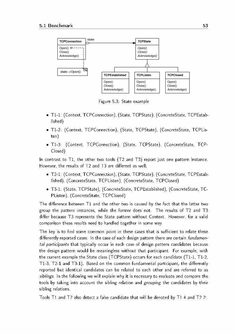
5.1 Benchmark 53
Figure 5.3: State example
• T1-1: (Context, TCPConnection), (State, TCPState), (ConcreteState, TCPEstab-lished)
• T1-2: (Context, TCPConnection), (State, TCPState), (ConcreteState, TCPLis-ten)
• T1-3: (Context, TCPConnection), (State, TCPState), (ConcreteState, TCP-Closed)
In contrast to T1, the other two tools (T2 and T3) report just one pattern instance.However, the results of T2 and T3 are di�erent as well:
• T2-1: (Context, TCPConnection), (State, TCPState), (ConcreteState, TCPEstab-lished), (ConcreteState, TCPListen), (ConcreteState, TCPClosed)
• T3-1: (State, TCPState), (ConcreteState, TCPEstablished), (ConcreteState, TC-PListen), (ConcreteState, TCPClosed)
The di�erence between T1 and the other two is caused by the fact that the latter twogroup the pattern instances, while the former does not. The results of T2 and T3di�er because T3 represents the State pattern without Context. However, for a validcomparison these results need to handled together in some way.
The key is to �nd some common point in these cases that is su�cient to relate thesedi�erently reported cases. In the case of each design pattern there are certain fundamen-
tal participants that typically occur in each case of design pattern candidates becausethe design pattern would be meaningless without that participant. For example, withthe current example the State class (TCPState) occurs for each candidate (T1-1, T1-2,T1-3, T2-1 and T3-1). Based on the common fundamental participant, the di�erentlyreported but identical candidates can be related to each other and are referred to assiblings. In the following we will explain why it is necessary to evaluate and compare thetools by taking into account the sibling relation and grouping the candidates by theirsibling relations.
Tools T1 and T2 also detect a false candidate that will be denoted by T1-4 and T2-2:

54 Validation of design pattern miner tools
• T1-4: (Context, FalseContext), (State, FalseState), (ConcreteState, FalseCon-creteState)
• T2-2: (State, FalseState), (ConcreteState, FalseConcreteState)
Hence several true candidates (T1-1, T1-2, T1-3, T2-1 and T3-1) were discoveredby using the tools and some false candidates were also discovered (T1-4 and T2-2).Evaluating the tools without grouping their �ndings yields the following results:
• T1 originally discovers 4 candidates. The T1-1,T1-2 and T1-3 candidates are true,while only T4-4 is false. This means that the precision for T1 is 75%.
• T2 discovers one true (T2-1) and one false candidate (T2-2). This means thatthe precision for T2 is 50%.
• T3 discovers only one true (T3-1) candidate so its precision score is 100%.
From a precision viewpoint, the best tool is T3 (100%), the second one is T1 (75%) andthe third one is T2 (50%). However, T1 is better than T2 because T1 reports a newcandidate in the case of each ConcreteState participant. In a fair comparison we needto consider the sibling relations and group the �ndings of T1. Then the T1 precisionscore changes to 50% because T1-1, T1-2 and T1-3 are grouped into one candidate. Inthis way the precision scores of T1 and T2 become the same.
Furthermore, when comparing the original �ndings of tools T1, T2 and T3, the inter-section of their results is empty, which is misleading. In contrast, if the grouping isperformed on all candidates by their sibling relations then T1-1, T1-2, T1-3, T2-1 andT3-1 will be grouped into one common candidate and the intersection of the tools willbe this one common candidate, as it should be. In summary, grouping candidates bytheir sibling relations has three use cases:
• The evaluation of a tool requires grouping its candidates, as in the case of T1:T1-1, T1-2 and T1-3 were grouped in the previous example.
• Comparing the tools requires grouping their candidates like that shown in theprevious example. (T1-1, T1-2, T1-3, T2-1 and T3-1 were grouped).
• Developers who evaluate design pattern candidates �rst have to understand thecurrent candidate context and connections in depth by examining the appropriatesource code fragments. This is the most time-consuming part of the evaluation.Evaluating sibling candidates one after the other can save a lot of time becausethe context only has to be understood for the �rst candidate.
5.1.3 Upload �le format.
The format of the DEEBEE's CSV �le containing the design pattern candidates mustbe the following (see Figure 5.4). Each pattern candidate consists of several lines ter-minated by a blank line. The �rst line of each candidate is always the pattern name,

5.1 Benchmark 55
without any white space characters. If the name consists of several words, then theyhave to be concatenated and each new word should start with an upper case letter(CamelCase). The subsequent lines represent the participants of the candidate. Theselines contain values separated by commas. The �rst value contains the role that maybe class, operation and attribute. If the participant is fundamental, then a star hasto be given before the role in the �rst value (see the class State in Figure 5.4). Thesecond value contains the name of the participant as written the source code. Lastly,the third value contains the relative path of the participant in the source code togetherwith starting and ending line information separated by colons.
State
class Context,TCPConnection,TCPConnection.h:1:6
operation Request,Open,TCPConnection.cpp:3:15
operation Request,Close,TCPConnection.cpp:15:25
operation Request,Acknowledge,TCPConnection.cpp:25:32
∗class State,TCPState,TCPState.h:1:6operation Handle,Open,TCPState.cpp:3:15
operation Handle,Close,TCPState.cpp:15:19
operation Handle,Acknowledge,TCPState.cpp:19:23
class ConcreteState,TCPListen,TCPListen.h:1:6
operation Handle,Open,TCPListen.cpp:3:12
operation Handle,Close,TCPListen.cpp:12:18
operation Handle,Acknowledge,TCPListen.cpp:18:23
Figure 5.4: CSV �le for the T1-2 candidate of the previous example
The uploaded pattern candidates are checked to see if they exist in the database. If aknown pattern candidate is found again by the new tool, and the two candidates areexactly the same, then the tool entry of the candidate is extended by the name of thenew tool, and no new candidate will be created in the database. If only the fundamentalparticipants are the same, then a new candidate will be created and the candidates willbe related as siblings.
5.1.4 Benchmark contents
The benchmark contains 1,274 design pattern candidates from three C++ software sys-tems (Mozilla [58] NotePad++ [60] and FormulaManager [81]), three Java softwaresystems (JHotDraw [46], JRefactory [48] and JUnit [49]) and C++ reference implemen-tations of design patterns. The uploaded design pattern candidates are recovered bythree design pattern miner tools: Columbus (C++), Maisa (C++) and Design Pattern

56 Validation of design pattern miner tools
Detection Tool (Java) [84] [27]. Table 5.1 shows the distribution of the candidatesamong tools and subject systems1.
Subject system Columbus 3.5 Maisa 0.5 DPD3 Human
Mozilla1.8a5 495 - - -NotePad++3.9 13 27 - 11ReferenceC++ 15 12 - 24JHotDraw - - 322 -JRefactory - - 259 -JUnit - - 7 -FormulaManager 56 32 - 40
Table 5.1: Distribution of uploaded candidates
5.2 Usage scenarios
Before describing the usage scenarios, we will provide an overview of the benchmark'sfunctionalities. The benchmark contains three main menu points, namely evaluation,upload and register. From the evaluation menu point, three important views can beaccessed. These are the statistics view, comparison view and the instance view. Fromthe upload menu point, the new language, new software, new tool and new instances
functionalities can be accessed. Figure 5.5 shows a map of the views and functionalities ofthe benchmark (e.g. query view can be accessed from evaluation menu, while comparisonview can be accessed from statistics view).
5.2.1 Browsing the database
In this scenario we will present di�erent queries and views with which the content ofthe benchmark database can be readily explored. In each case we will �rst give a briefdescription of the view or functionality, and afterwards demonstrate it by supplying anexample.
Query view. As the primary aim of our benchmark is to evaluate and classify theresults of design pattern miner tools (the design pattern candidates), the �rst thing oneshould do is to decide how the candidates are to be listed, which is controlled by aspects.There are four aspects in the benchmark, namely software, tool, pattern and language
which can be adjusted in any particular order (it is not necessary to set every aspect).For each aspect, di�erent parameters can be set which in�uence the result. The number

5.2 Usage scenarios 57
Figure 5.5: Functionalities of the benchmark
Figure 5.6: Query view of DEEBEE
of possible parameter values will increase during the evolution of the benchmark becausenew patterns, languages, software packages and tools will be added.
1The tools found same candidates, so summarizing the values in the table will be greater than 1,274

58 Validation of design pattern miner tools
Example: Figure 5.6 shows a screenshot of the query view. This example gives anordering where the �rst aspect is the language with the parameter set to C++. Thesecond aspect is software set to NotePad++. The following two aspects are tool andpattern with parameters set to all. By pressing the button �Go to results view� , theresults view will be generated.
Results view. After running query, the results table is generated (see Figure 5.7). Thecolumns (except the last one) correspond to the previously selected aspects. The lastcolumn contains the identi�ers of the design pattern candidates which satisfy the criteriaprovided by the aspects. By clicking on one of the candidate identi�ers, the Instance
view will show up, while by clicking on the links in the other columns, the Statistics viewwill be accessed.
Figure 5.7: Results view of DEEBEE
Example: Based on the previously selected ordering aspects in the query view, we got atable where the top left link is C++ (see Figure 5.7). The second column contains a linkto the NotePad++ software in accordance with the query. Because we queried all toolsand patterns (third and fourth aspects), we got all the tools which currently participatein the benchmark and all pattern candidates found by these tools in NotePad++.
Instance view. The instance view provides the user interface for evaluating designpattern candidates (see Figure 5.8). The participants of the actual pattern candidateare shown in the top left corner with their concrete name in the source code. When theuser clicks on a participant name, the source code is shown with the pattern candidatehighlighted on the right hand side of the view. A design pattern candidate (instance)may be evaluated using two categories:

5.2 Usage scenarios 59
Figure 5.8: Instance view with highlighted source code in DEEBEE
• Completeness means how complete the evaluated pattern candidate is in a struc-tural sense. More precisely, it means how many pattern participants can be foundin the candidate. In this category, the possible answers are the following:
� The pattern instance is complete in every aspect.
� Some participants are missing from the pattern instance.
� Important participants are missing from the pattern instance.
• Correctness means how correct the evaluated pattern candidate is in a behaviouralsense. More precisely, it means to what degree the pattern candidate matches theoriginal intent of the design pattern. In this category, the possible answers are thefollowing:
� I am sure that it is a real pattern instance.
� I think that it is a real pattern instance.

60 Validation of design pattern miner tools
� I think that it is not a real pattern instance.
� I am sure that it is not a real pattern instance.
The evaluation answers, Completeness and Correctness can be applied to the siblings ofthe pattern candidate as well (if there are any) by selecting the corresponding checkboxes.Most of the time sibling candidates are evaluated equally, hence the siblings of the patterncandidate are also listed in the instance view to help the user in the evaluation.
It can also be queried for statistics about the previous evaluations of the pattern can-didate. The result will appear on the right hand side of the view (see Figure 5.9).User comments can be added to the pattern candidate at the bottom of the instanceview. Registration needs to be performed to evaluate a pattern candidate and to add acomment.
Example: We shall continue with the previous example. After clicking on candidate #32in the results view (see Figure 5.7), the instance view will show up (see Figure 5.8). Ifwe select the participant called StaticDialog, then its syntax-highlighted source code willbe automatically loaded into the right hand side of the view, which can be evaluatedimmediately inside the benchmark environment. Statistics about past evaluations areavailable for completeness and correctness by clicking on the stat links next to thecorresponding questions. In the case of pattern candidate #32, both candidate statisticsresults are shown in Figure 5.9.
Figure 5.9: Instance view statistics in DEEBEE
Statistics view. The statistics view gives statistical data about the entity clicked inthe results view (see Figure 5.7) together with all other entities which depend on it. Theview contains two tables - one for correctness and one for completeness, respectively(see Figure 5.10).
Each line in the upper part of each table contains a statistic for one particular patterncandidate. A pattern candidate may be evaluated by some people, so the mean, devia-tion, minimum, maximum and median values are calculated for the candidate. The lowerpart of each table contains the same kind of basic statistics, but they are calculated fromthe statistics of the candidates (shown in the upper part of each table).

5.2 Usage scenarios 61
Figure 5.10: Statistics view of DEEBEE
Below, the correctness table precision and recall are given2. These values are basedon a human evaluation of the candidates and on a threshold value, which by defaultis 50%. This means that a pattern candidate found by a tool is considered to be aninstance (true positive) if the average score of the evaluation of its correctness is at least50%. The benchmark can be customized to take into account sibling relations or notwhen generating statistics. The default option is to handle sibling candidates as onlyone common candidate. If the sibling relations are considered, then the least candidateidenti�er will denote the grouped candidates and it is marked in red instead of blue.
Example: Go from the instance view (Figure 5.8) to the results view (Figure 5.7) byclicking on the �Back to previous view� link. On the results view interface, click on theC++/NotePad++3.9/Maisa0.5/Proxy link in the table. This takes us to the statisticsview, which is shown in Figure 5.10.
5.2.2 Evaluating and comparing tools
In this scenario we will show how design pattern miner tools can be evaluated andcompared using our benchmark. The example gives the evaluation and comparison ofColumbus 3.5 and Maisa 0.5 on reference implementations of the GOF patterns in C++.
First, the Evaluation menu has to be selected and the following query should be set (seeFigure 5.6):
• 1. aspect: �Software� with parameter set to �ReferenceC++�.
• 2. aspect: �Tool� with parameter �All�.
2The de�nition of precision and of recall are both given in Section 2.2.

62 Validation of design pattern miner tools
• 3. aspect: �None� with parameter �All�.
• 4. aspect: �None� with parameter �All�.
Pressing the �Go to results view� button will generate the results view (which is similarto Figure 5.7).
In the results view by clicking on the �ReferenceC++� link in the top left corner wegot the statistics view (which is similar to Figure 5.10). Here we can see the statisticson the results of Columbus and Maisa. In the case of Columbus, the precision score is100% and the recall score is 58.33%. In the case of Maisa these are 80% and 33.33%,respectively. Here we used the default threshold value of 50% (see Section 5.2.1).
The benchmark provides another interesting view, called comparison view, for comparingthe capabilities of pattern miner tools. The page can be accessed from the statistics viewby clicking on the Switch to comparison view link. The �rst table in Figure 5.11 shows thepattern candidates found by Maisa and by Columbus in the reference implementationof the GOF patterns (rows A and B). This table also shows the di�erences and theintersection of the candidates found by the tools which were compared (rows A-B, B-Aand A&B). It can be seen in row A-B that Maisa found one pattern candidate (#1152, aMemento candidate), which was not found by Columbus. Row B-A shows 7 candidatesfound by Columbus and not found by Maisa. Row A&B shows those 7 candidates whichare found by both tools.
The comparison view contains two other tables showing the results of a comparison ofMaisa and Columbus with the results of human inspection of the code, respectively.The instances found by careful human inspection represent the desirable results of atool. Therefore, the di�erence between e.g. Human and Columbus represents the false
negatives for Columbus. (This value is used for calculating the recall values.) Thisway the false negatives of a tool can be quickly and e�ciently discovered using thebenchmark.
5.2.3 Adding a new tool
In this scenario we will show how the results of a new design pattern miner tool can beadded to the benchmark. Uploading the results of a tool requires the the tool name,name of the mined software, the software programming language, source location, andinformation about the design pattern candidates found in the comma separated value(CSV) �le format (see Figure 5.12 and Section 5.1.3).
To upload design pattern candidates, public access to the source code of the minedsoftware has to be given. This is important because the source code is used in theinstance view to show and evaluate pattern participants. There are two possible ways toprovide access to the source code: via http and svn.

5.2 Usage scenarios 63
Figure 5.11: Comparison view of DEEBEE

64 Validation of design pattern miner tools
Figure 5.12: Adding the results of a new tool to DEEBEE
Example: In the example we will add a new tool called Dummy Pattern Miner v0.1 tothe benchmark. The mined software will be the reference implementation of the GOFpatterns in C++. Figure 5.12 lists the completed forms.
5.3 Experiments performed
Here Columbus and Maisa were evaluated and compared using the benchmark. The toolswere evaluated on C++ reference implementations of design patterns, on NotePad++,and on a program called FormulaManager implemented by us to have a test case wherethe use of design patterns is well de�ned and documented. The reference implementa-tions test the structural matching ability of the tools, while in the case of NotePad++and FormulaManager the tools were examined in a real-life context where other fac-tors are also considered, like the goal of the pattern. Columbus provides the commonframework for the experiment (see Figure 5.13).
Reference implementations. To compare di�erent tools, reference implementationsof design patterns based on book by Gamma et. al. [39] were created by us. With thesereference implementations the basic capabilities of C++ pattern miner tools can beevaluated and compared.
Design pattern mining strongly depends on the analysis of the source code. Hence thesource �les in the reference implementations do not contain any di�cult programmingstructures like templates and they do not include any standard headers to avoid parsingproblems.

5.3 Experiments performed 65
Figure 5.13: Framework for design pattern mining
Let us take a concrete reference implementation, the Adapter Object3. The referenceimplementation of Adapter Object is shown in Figure 5.14. In reference implementationseach participant class starts with the �Example_� pre�x; similarly, attributes start withthe �example_� pre�x.
NotePad++ is a free source code editor which supports several programming lan-guages, running in Microsoft Windows environments. It is based on the Scintilla editorcomponent (a very powerful editor component), written in C++ with pure win32 APIand STL. Calculated by the metric component of Columbus, NotePad++ contains 95classes, 1,371 methods, 776 attributes and 27,033 useful lines of code.
When evaluating design pattern miner tools on real software systems, it is necessary toconsider not only candidates mined by the tools, but instances recognized by us as well.If instances mined by programmers are skipped in an evaluation then the recall of thetools cannot be calculated. Therefore instances from NotePad++ recovered manuallywere also added to the benchmark and were examined during the evaluation of Columbusand Maisa.
FormulaManager. Since the reference implementations contain disjoint implemen-tations of the design patterns in an unreal context, we developed a program called
3We introduced this pattern earlier in Section 3.2.1

66 Validation of design pattern miner tools
class Example_Target {
public:
virtual void function() = 0;
};
class Example_Adaptee {
public:
virtual void other_function();
};
class Example_AdapterObject : public Example_Target {
public:
virtual void function();
private:
Example_Adaptee* m_adaptee;
};
void Example_Adaptee::other_function() {
}
void Example_AdapterObject::function() {
m_adaptee->other_function();
}
Figure 5.14: Reference implementation of Adapter Object
FormulaManager where each design pattern occurs in a real context at least once. Thegoal of FormulaManager is to manage formulas, namely execute operations on formulas(evaluation, pre�x form, post�x form), export the results to di�erent kinds of represen-tations (HTML, XML, CSV), display the results in di�erent views (list, table), handledi�erent numbering systems and validate a formula.
Tables 5.2, 5.3 and 5.4 present the results obtained from using the tools, where the upperpart shows the number of candidates found. In the lower part of the tables a summary isshown as well, where precision, recall, the correctness mean and the completeness meanare provided by the benchmark's statistics view (see Section 5.2.1). A dash in the tablesshows that the tool did not search for the given pattern.
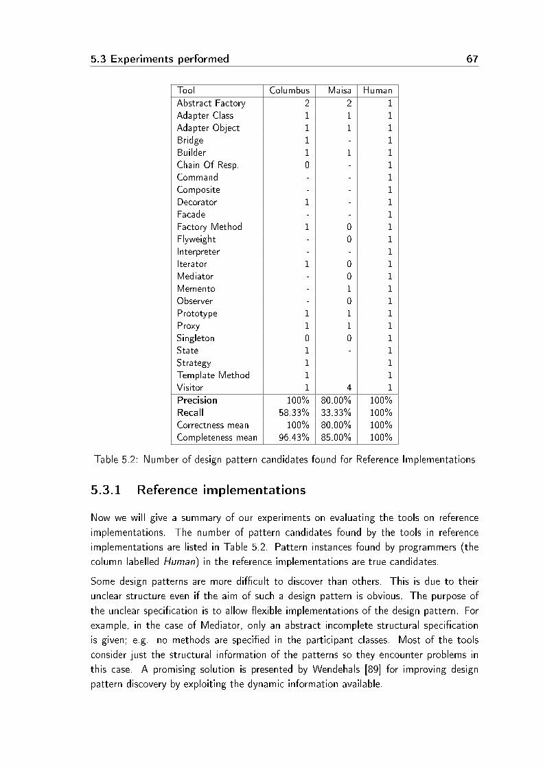
5.3 Experiments performed 67
Tool Columbus Maisa Human
Abstract Factory 2 2 1Adapter Class 1 1 1Adapter Object 1 1 1Bridge 1 - 1Builder 1 1 1Chain Of Resp. 0 - 1Command - - 1Composite - - 1Decorator 1 - 1Facade - - 1Factory Method 1 0 1Flyweight - 0 1Interpreter - - 1Iterator 1 0 1Mediator - 0 1Memento - 1 1Observer - 0 1Prototype 1 1 1Proxy 1 1 1Singleton 0 0 1State 1 - 1Strategy 1 - 1Template Method 1 - 1Visitor 1 4 1
Precision 100% 80.00% 100%Recall 58.33% 33.33% 100%Correctness mean 100% 80.00% 100%Completeness mean 96.43% 85.00% 100%
Table 5.2: Number of design pattern candidates found for Reference Implementations
5.3.1 Reference implementations
Now we will give a summary of our experiments on evaluating the tools on referenceimplementations. The number of pattern candidates found by the tools in referenceimplementations are listed in Table 5.2. Pattern instances found by programmers (thecolumn labelled Human) in the reference implementations are true candidates.
Some design patterns are more di�cult to discover than others. This is due to theirunclear structure even if the aim of such a design pattern is obvious. The purpose ofthe unclear speci�cation is to allow �exible implementations of the design pattern. Forexample, in the case of Mediator, only an abstract incomplete structural speci�cationis given; e.g. no methods are speci�ed in the participant classes. Most of the toolsconsider just the structural information of the patterns so they encounter problems inthis case. A promising solution is presented by Wendehals [89] for improving designpattern discovery by exploiting the dynamic information available.

68 Validation of design pattern miner tools
Because the two evaluated tools use only structural information, they do not discovermost of the patterns with unclear speci�cation, e.g. Command, Facade and Interpreter,as can be seen in Table 5.2. Although Maisa seeks to discover some patterns that havean unclear speci�cation like Mediator, Memento, Observer and Flyweight, it works onlyin the case of Memento (candidate #1152). Because Maisa failed to �nd these patterns,its recall score is only 33.33%.
If several pattern candidates were discovered in the reference implementations for a givenpattern, then either false positives were found or the pattern instance was recognized
several times. For instance, Maisa discovered four Visitor pattern candidates. We ex-amined these candidates in the benchmark and realized that two of them were falsepositives, while the other two instances were actually the same instance with a commonabstract, but with di�erent concrete participants. The two true instances were relatedas siblings (see Section 5.1) to each other and to the single pattern instance found byColumbus and Human. This way, these instances appear as one common instance in thebenchmark.
Figure 5.15: Visitor candidate mined by Maisa from reference implementations
Figure 5.15 shows the instance view of one of the two false Visitor candidates mined by

5.3 Experiments performed 69
Maisa (candidate #1169). The source of Example_ConcreteElement2 class is loadedinto the right hand side of the view because it was selected previously from the par-ticipants. It is a false candidate because Example_ConcreteElement2 acts as a classElement participant, as can be seen in the participants' area (see Figure 5.15). Maisadiscovered another false candidate because it made the same mistake (#1171).
In the case of Abstract Factory, both Maisa and Columbus discovered two pattern can-didates. These pattern candidates are true, the only problem being that neither toolcan group concrete elements of the Abstract Factory pattern, so they discovered thesame pattern instance twice with di�erent concrete participants. It caused the mean ofColumbus' completeness to be 96.43%. Maisa had a similar problem in the case of theVisitor pattern so its mean of completeness is 85%.
Comparison. The candidates found by Columbus, Maisa and humans were comparedby the comparison view module of the benchmark (see Figure 5.16). Let us examinethe �rst table in Figure 5.16. This table shows a comparison of all candidates foundby Maisa and Columbus (no threshold was set as it was in case of Figure 5.11). Thedi�erence between Maisa and Columbus (row A-B) contains three pattern candidates.The previously mentioned false positive Visitor candidates (#1169 and #1171) wereonly found by Maisa, so these appear in the di�erence. The other di�erence is a truepositive pattern candidate of Memento (#1152), which was found by Maisa but notby Columbus. Because Columbus found several design patterns that Maisa did not, alot of instances appear in the di�erence between Columbus and Maisa (row B-A). Butthe tools found some patterns in common, with the same results that appear in theintersection (row A&B).
5.3.2 NotePad++
After examining the tools on the reference implementations, we performed another test,but this time on the real project called NotePad++. The results obtained from usingthe tools can be seen in Table 5.3, which will be elaborated on below.
Columbus only found a couple of types of patterns (Adapter Object, State and TemplateMethod), but with better precision than those (Adapter Class, Adapter Object, Builder,Prototype and Proxy) found by Maisa. It should also be remarked that software devel-opers tend to �nd those pattern instances which are di�cult to �nd by pattern minertools because of their unclear speci�cations. Therefore, we think that instances found byhumans are a good supplement to the use of automatic tools even if software developersdo not �nd all the pattern instances in a particular project.
In Table 5.3 we see that the precision of Human on NotePad++ is not 100%. This isdue to the fact that the results of Human in the benchmark consist of several people

70 Validation of design pattern miner tools
Figure 5.16: Comparison of candidates in reference implementations
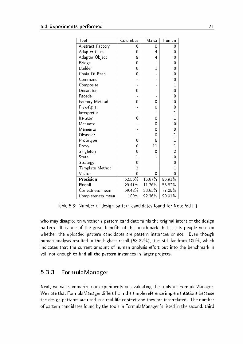
5.3 Experiments performed 71
Tool Columbus Maisa Human
Abstract Factory 0 0 0Adapter Class 0 4 0Adapter Object 9 4 0Bridge 0 - 0Builder 0 1 0Chain Of Resp. 0 - 0Command - - 0Composite - - 1Decorator 0 - 0Facade - - 0Factory Method 0 0 0Flyweight - 0 0Interpreter - - 1Iterator 0 0 1Mediator - 0 0Memento - 0 0Observer - 0 1Prototype 0 6 1Proxy 0 11 1Singleton 0 0 2State 1 - 0Strategy 0 - 0Template Method 3 - 1Visitor 0 0 0
Precision 62.50% 16.67% 90.91%Recall 29.41% 11.76% 58.82%Correctness mean 69.42% 20.63% 77.05%Completeness mean 100% 92.36% 90.91%
Table 5.3: Number of design pattern candidates found for NotePad++
who may disagree on whether a pattern candidate ful�ls the original intent of the designpattern. It is one of the great bene�ts of the benchmark that it lets people vote onwhether the uploaded pattern candidates are pattern instances or not. Even thoughhuman analysis resulted in the highest recall (58.82%), it is still far from 100%, whichindicates that the current amount of human analysis e�ort put into the benchmark isstill not enough to �nd all the pattern instances in larger projects.
5.3.3 FormulaManager
Next, we will summarize our experiments on evaluating the tools on FormulaManager.We note that FormulaManager di�ers from the simple reference implementations becausethe design patterns are used in a real-life context and they are interrelated. The numberof pattern candidates found by the tools in FormulaManager is listed in the second, third

72 Validation of design pattern miner tools
Tool Columbus Maisa Human
Abstract Factory 4 0 2Adapter Class 2 1 1Adapter Object 4 0 1Bridge 6 - 2Builder 1 0 1Chain Of Resp. 1 - 1Command - - 1Composite - - 1Decorator 1 - 1Facade - - 1Factory Method 2 3 4Flyweight - 1 1Interpreter - - 1Iterator 1 0 1Mediator - 0 1Memento - 0 1Observer - 0 1Prototype 3 2 2Proxy 2 0 1Singleton 3 0 3State 9 - 1Strategy 2 - 2Template Method 1 - 1Visitor 2 3 1
Precision 52.27% 80% 100%Recall 71.88% 25% 100%Correctness mean 55.23% 85.95% 100%Completeness mean 85.98% 48.02% 100%
Table 5.4: Number of design pattern candidates found for FormulaManager
and fourth columns of Table 5.4. Let us examine and compare the scores of Columbusand Maisa on FormulaManager. It is clear that Maisa has a good precision score (80%),but its recall score is poor (25%). The poor recall is due to the fact that Maisa failedto �nd the instances of several design patterns (e.g. Builder, Mediator, Proxy) and itdid not try to discover every kind of pattern (e.g. Command, Decorator). In contrast,Columbus has a fair recall score (71.88%) and precision score (52.27%). Columbus foundseveral false positives in the case of State, Bridge and Adapter Object, which resulted inits lower precision score compared to Maisa. In the case of the other patterns, Columbushas good precision scores.

5.4 Evaluation of the benchmark 73
5.4 Evaluation of the benchmark
Sim et al. [74] de�ned seven requirements for a benchmark. In this section we will citethe requirements, and afterwards give an evaluation of the benchmark based on them.
Accessibility. �The benchmark needs to be easy to obtain and easy to use. The test
materials and results need to be publicly available...� The benchmark is easy to obtain,it is online and accessible from the home page of the Institute of Informatics at theUniversity of Szeged [26].
A�ordability. �The cost of using the benchmark must be commensurate with the
bene�ts...� The only investment required is to extend the tool to be measured in thebenchmark to produce a CSV �le in a suitable format (see Section 5.2.3) for uploadingits results. If it is measured on a subject system that has already been inspected byprofessional software developers, then the results (e.g. precision and recall) will beimmediately available without any extra e�ort required.
Clarity. �The benchmark speci�cation should be clear, self-contained, and as short as
possible...� In the case of design pattern mining, it is clear that the tool has to �ndinstances of patterns in the source code. The most important inconsistency that weexperienced is that many tools tend to �nd the same pattern candidate several timesif there is e.g. a participant in the pattern description which is typically implementedin several ways (e.g. the ConcreteStrategy participant in the Strategy design pattern).Our benchmark includes the siblings mechanism to automatically deal with this issue.
Relevance. �The task set out in the benchmark must be representative of ones that
the system is reasonably expected to handle in a natural (meaning not arti�cial) setting
and the performance measure used must be pertinent to the comparisons being made...�
The benchmark contains reference implementations of the GOF design patterns [39]that test the basic capabilities of the tools. To test the tools on real-life cases, we alsouploaded pattern candidates found in real software by three well-known tools (Maisa,Columbus and Design Pattern detection Tool). There are also two software systemsin the benchmark that have already been inspected by experienced software developersconcerning design pattern usage (NotePad++ and FormulaManager).
Solvability. �It should be possible to complete the task domain sample and to produce a
good solution...� The benchmark contains subject systems of varying size and complexity,which makes it easier or harder to mine pattern instances from them. It contains referenceimplementations of design patterns expected to be found by all competing tools and real-life software systems to test their actual capabilities.
Portability. �The benchmark should be speci�ed at a high enough level of abstraction
to ensure that it is portable to di�erent tools or techniques and that it does not bias one
74 Validation of design pattern miner tools
technology in favour of others...� The benchmark is general; it is language, software,tool and pattern independent. It already contains pattern instances found in subjectsystems running on di�erent platforms and written in di�erent programming languages.
Scalability. �The benchmark tasks should scale to work with tools or techniques at
di�erent levels of maturity...� The benchmark contains reference implementations ofdesign patterns that can be utilized to test research prototypes and it also containsreal-life software systems to test mature tools like commercial products.
5.5 Summary
In this chapter we presented a newly developed benchmark and performed experimentson it for evaluating and comparing the precision and recall of design pattern minertools. The benchmark is general from the viewpoint of the mined software systems,programming languages, uploaded design pattern candidates, and design pattern minertools.
With the help of our benchmark the accuracy of two design pattern miner tools (Colum-bus and Maisa) were evaluated on reference implementations of design patterns and ontwo software systems, NotePad++ and FormulaManager. In this part design patterninstances used in NotePad++ were also discovered by hand, so both precision and recallscores can be calculated via the benchmark. Furthermore, we developed a software sys-tem called FormulaManager to test the tools on a program where each design patternis implemented in a real-life context.
Sometimes false candidates were found by the tools because they only examined thestructure of the code, while programmers also take the code's behaviour into account.This is why instances mined by humans can be used to provide additional results on topof those obtained by the tools.
With the help of our benchmark it was demonstrated that it is indeed possible to evaluatedesign pattern miner tools readily and e�ectively, which will hopefully lead to betterquality tools in the future. This benchmark is freely accessible from the home page ofthe Institute of Informatics at the University of Szeged:
http://www.inf.u-szeged.hu/designpatterns/

Chapter 6
Common format for design pattern
miner tools
�Most of the fundamental ideas of science are essentiallysimple, and may, as a rule, be expressed
in a language comprehensible to everyone.�
Albert Einstein
The previous chapters and other studies (e.g. fusing the results of tools [54]) highlightedseveral limitations of the current outputs of the design pattern detector (DPD) tools inform and content: some output formats (1) do not report either their own identity or thename and version of the program that they analyzed; (2) do not report all roles relevantto a given motif; (3) do not identify reported roles unambiguously; (4) do not identifydetected motif candidates unambiguously; (5) do not report their conceptual schemaof the identi�ed motif; (6) do not justify their results; and (7) use ad hoc (generallytextual) output formats. Point 1 makes it di�cult to reproduce the DPD tool results;point 2 makes it hard to combine results from di�erent tools; points 3 and 4 make resultsambiguous; point 5 makes a comparison of results di�cult; point 6 leads to problemswhen understanding and verifying the results; and, point 7 hinders the automated useof the results by other tools.
In the previous chapter, we introduced DEEBEE and described what it does. The CSVuploading format of DEEBEE was designed to represent information that is necessaryonly for evaluating and comparing the results of di�erent tools. In this way there is noguarantee that the CSV format of DEEBEE will satisfy any kind of tool that may workon the result of a design pattern miner like a visualization tool or a fusion tool.
We propose to address these limitations by introducing a common exchange format forDPD tools, called DPDX, based on a well-de�ned and extendible metamodel. Thisformat should aid the comparison [95], fusion [53], visualization [29], and validation [97]of the outputs of di�erent DPD tools.
Consequently, the contributions of this chapter are twofold. First, we provide a goodfoundation for DPD. Second, we propose a common exchange format for DPD toolsthat fosters their synergetic use and supports the automated processing of their results.
75

76 Common format for design pattern miner tools
6.1 Background
6.1.1 Motivation
A common exchange format for DPD tools would be bene�cial to achieve a synergyof many di�erent tools. Our vision is illustrated in Figure 6.1, where a federation oftools based on the common exchange format interact to produce new values. Thisfederation and the common format is also an invitation to program comprehension andmaintenance, and for re-engineering research communities to contribute individual tools,including tools unforeseen in the vision given in Figure 6.1.
DPD result repository DPD result repository
VisualisationDetection Result FusionVisualisationDetection Result Fusion
VisualisationDetection Result Fusion
DPDX - Common DPD Result Interchange Format
Figure 6.1: A federation of design pattern detection, visualization and assessment toolscooperating via the common exchange format.
For example, visualizations of DPD outputs could be built entirely using the commonexchange format, instead of being implemented separately for each DPD tool. Next, itshould be possible to automate the process of collecting, comparing, and evaluating theoutputs of di�erent tools, which is currently a manual, error-prone, and time-consumingtask. Then public repositories of instances of design motifs (P-MARt [61], DEEBEE [97])should bene�t greatly from a common exchange format. These repositories are importantin DPD research as a reference for assessing the accuracy of tools [63]. Moreover,a common exchange format would also help in achieving an automated round-trip inDPD tools (see Albin-Amiot et al. [2]), including pattern detection, collection, fusion,visualization, validation, storage, and generation.
6.1.2 Requirements
The common exchange format must ful�l the following core requirements to address thelimitations of current DPD tools outputs and serve as the basis for a federation of tools:
1. Speci�cation. The exchange format must be speci�ed formally to allow DPDtool developers to implement appropriate generators, parsers, and/or converters.

6.1 Background 77
2. Reproducibility. The tool and the program to be analyzed must be explicitlyreported to allow researchers to reproduce the results.
3. Justi�cation. The format must include explanations of results and scores ex-pressing the con�dence of a tool in its diagnostics to help experts and tool usersdigest and apply the reported results.
4. Completeness. The format must be able to represent program constituents atevery level of role granularity described in design pattern literature.
5. Identi�cation of role players. Each program constituent playing a role in adesign motif must be unambiguously identi�ed.
6. Identi�cation of candidates. Each candidate must be unambiguously identi�edand reported only once.
7. Comparability. The format must allow one to report the motif de�nitions as-sumed by a tool and the applied analysis methods to allow other tool users tocompare results.
In addition to the previous core requirements, the following two optional requirementsare also desirable:
1. Language-independence. The common exchange format should abstract lan-guage speci�c concepts so that it can be used to report candidates identi�ed inprograms written in arbitrary imperative programming languages (including object-oriented languages).
2. Standard-compliance. The speci�cation should be consistent with existing stan-dards so that it can be easily adapted, maintained, and evolved.
6.1.3 State of the art
We evaluated the output formats of several existing DPD tools (SPQR [79], DP-Miner[28], Fujaba [89, 91], Maisa [34, 57], SSA [84], Columbus [8], PINOT [70], Ptidej[41]) and of two DPD result repositories (DEEBEE [96],[97] and p-MARt [61]) from theviewpoint of the requirements listed above. The conclusions presented below are basednot just on a thorough literature review, but also on intensive practical evaluations [53],[96], [100] of all tools except SPQR, which is not publicly available.
Each of the reviewed output formats for describing design pattern candidates containssome elements that are worth using in a general exchange format. In particular, eachful�ls the Language Independence requirement, i.e. they contain no language speci�cinformation. Despite this, there is no format available that would ful�l all of our require-ments.

78 Common format for design pattern miner tools
Tool DP-Miner
Maisa SSA SPQR Colum-bus
Pinot Ptidej Fujaba DEEBEE P-Mart
Language-
independence
√ √ √ √ √ √ √ √ √-
Completeness -√
-√ √ √
-√ √
-Standard
compliance
CSV - XML XML - - - XML CSV XML
Identi�cation
of role players
- - Nestedclasses
- Outerclasses
Outerclasses
Outerclasses
ClassesSigna-tures
Classesmethods�elds
Classes
Identi�cation
of candidates
- -√ √ √
-√
- UniqueIDs
-
Justi�cation - - - - - - Scoresexpla-nations
Scores - -
Comparability - - - - - - - - - -Reproducibility - - - - - - - - Tool and
repositoryinfo
Repositoryinfo
Speci�cation - - - - - - - - - Roletypes
Table 6.1: Tools and requirements satis�ed by their output formats
Table 6.1 shows that four formats (of DP-Miner, SSA, PTidej and P-Mart) do not ful�lCompleteness by not reporting all the relevant roles. Half of the tools analyzed by us usead hoc formats, thus they fail to ful�ll Standard Compliance. The formats of DP-Minerand DEEBEE exchange are based on a quasi standard called CSV, but unfortunately onethat fails unambiguity since even classes are not identi�ed uniquely (only by their name).However, it is worth noting that the other standard compliant output formats structureinformation using XML syntax, which supports nesting and therefore recommends itselfas a good basis for a general exchange format.
All formats (except the output format of SSA) either do not support Identi�cation of
Role Players at all or just for a limited set of program elements, mostly outer classes.Fujaba is the only one that supports classes and method / �eld signatures. No formatsupports the unambiguous identi�cation of elements at �ner grained levels (individualstatements). We noted that line numbers are not a satisfactory identi�cation scheme.
Obviously, all the reviewed output formats are mainly intended to satisfy a human expert.They assume much implicit knowledge about programming languages and design patternsthat a software engineer typically has, but which an automated tool does not. Typically,none of the tools provide explicit schemata of the searched design motifs, which wouldhelp other tools to understand their conceptual model of a pattern, and information aboutanalysis methods employed. Therefore the Comparability requirement is not ful�lled byany tool.
DP-Miner does not ful�l Identi�cation of Candidates since it can repeat the same can-didate with the same role assignments. Identi�cation of Candidates is not ful�lled byMaisa, PINOT and Fujaba because when a candidate has several method/�elds play-ing the same role, these tools report multiple candidates (one for each method/�eld).

6.2 DPDX concepts 79
SSA does not report multiple candidates in such cases. By reporting only mandatoryclass roles, a candidate is identi�ed unambiguously, hence Identi�cation of Candidates
is ful�lled.
Ptidej, DEEBEE, Columbus and SPQR ful�l Identi�cation of Candidates since theymerge di�erent candidates that have the same mandatory role assignments. Repro-
ducibility is ful�lled partly by P-Mart (only repository names and versions are included)and DEEBEE. We should add that P-Mart reports role kinds for class roles (Class, Ab-stract Class, etc.). Therefore we could claim that Speci�cation is partly ful�lled (onlyby P-Mart). Last, but not least, only two tools (Ptidej and Fujaba) report con�dencescores and only one tool (Ptidej) provides explanations. Ptidej, which provides explana-tions about violated and ful�lled constraints, implicitly hints at constraint satisfactionas the analysis technique employed.
The output formats of the above tools are shown in the Appendix (see Section B.1),while a detailed evaluation and comparison of the formats were published in our technicalreport [100].
6.2 DPDX concepts
Now we shall develop the concepts on which our proposed exchange format, DPDX, isbased. We will show how DPDX addresses each of the requirements stated in Section6.1.2, overcoming the limitations of existing output formats identi�ed above.
6.2.1 Speci�cation
The common exchange format will be speci�ed by a set of extendible metamodels thatcapture the structural properties of the relevant concepts, such as candidates, rolesand their relations. Metamodels that re�ect the decisions explained in this section arepresented in Section 6.3. They signi�cantly extend previous similar proposals, like thePADL metamodel of Albin-Amiot et al. [3]. The possible kinds of program constituentsand the related abstract syntax tree are not �rst-class elements of the metamodel, butare captured by a set of prede�ned values for certain attributes in the metamodel. Thisensures easy extendibility since only the set of values must be extended to capturenew relations or language constructs, while the metamodel and the related exchangeformat remain stable. The set of de�ned terms can be viewed as a simple ontology.Ontologies have already been used in the domain of design pattern detection. Forexample, Kamp�meyer et al. [51] showed that an ontology can be used to model theintents of design patterns. Their proposed ontology is useful for automatically relatingdesign patterns to one another.

80 Common format for design pattern miner tools
6.2.2 Reproducibility
A DPD result �le must contain the diagnostics of a particular DPD tool for a particularprogram. To allow reproducibility of the results, it must include the name and version ofthe tool employed and the name, version, and the URI of the program being analyzed.Names and versions may be arbitrary strings. The URI(s) must reference the rootdirectory(ies) of the program being analyzed. The URI �eld is optional, since the programbeing analyzed might not be publicly accessible. The other �elds are mandatory.
6.2.3 Justi�cation
The justi�cation of diagnostics consists of con�dence scores, reported as real valuesbetween 0 and 1, and textual explanations. Justi�cation information can be added ateach level of granularity: i.e. for a complete candidate, individual role assignments andindividual relation assignments.
6.2.4 Completeness
To identify a candidate unambiguously, each program constituent that may play a manda-tory role must be reported (Identi�cation of Candidates requirement). Therefore, DPDXallows the reporting of each of the following constituents: nested and top-level types
(interfaces, concrete and abstract classes); �elds and methods; any statements (includ-ing �eld accesses and method invocations). Reporting role mappings at all possiblegranularity levels improves the presentation of the results and aids their veri�cation byexperts and use by other tools. Reporting roles used by statements di�erent from in-vocations and �eld accesses is important because they are essential for disambiguatingcertain motifs.
6.2.5 Identi�cation of role players
The main part of a DPD result �le consists of role mappings, i.e. assignments of programconstituents to the roles that they play in a motif. Given a particular program versionand program constituent description, it should be possible to identify the constituentprecisely and unambiguously in the program. In addition, it would be bene�cial if theidenti�cation scheme were stable, i.e. if it were not a�ected by changes in the sourcecode that are mere formatting issues or the reordering of elements whose order has nosemantic meaning. For instance, after inserting a blank line or changing the order ofdeclarations, each program element should still have the same identi�er as before. Thisis necessary to compare DPD results across di�erent program versions, when analyzingthe evolution of design pattern implementations over time.

6.2 DPDX concepts 81
Identifying named elements According to Completeness, we must unambiguouslyidentify program elements down to the granularity level of individual statements.
Stable identi�cation is easy for type and �eld declarations, which are typically labelled.Chaining names from outer to inner scopes is su�cient for identifying declarations ofclasses and �elds. For instance, in the example presented in Figure 6.2, myApp.A iden-ti�es class A and myApp.B.b identi�es �eld b of class B.
package myApp ;
c l a s s A { pub l i c void f ( i n t a , i n t b ) { . . . } }
c l a s s B {
i n t b ;
pub l i c void b (B b ) { . . . }
pub l i c void b (A a ) {
i n t c , d ;
i f ( . . . ) a . f ( c , d ) e l s e a . f ( d , c ) ;
}
}
Figure 6.2: Named and unnamed elements example
Because in many object-oriented languages methods can be overloaded, unique identi�-cation requires including the types of method arguments in the identi�er of a method.
Identifying unnamed elements Alas, nested naming is unsuitable for �ne-grainedelements (statements and expressions), which may occur several times in the same scope,e.g. in the same method body or �eld initializer expression. Cases like the two invocationsof method f() within the body of method B.b(myApp.A) in Figure 6.2 can neither bedisambiguated by additionally reporting the static type of invocation arguments (whichis the same in both cases) nor by adding line number information (which anyway failsthe stability requirement).
However, each element can be identi�ed uniquely by a path in an abstract syntax tree(AST) representation of the respective program. This path consists of names for thechild branches of each AST element and positions within statement sequences. Wecall this the model-based identi�cation scheme since it assumes a standardized modelof an abstract syntax tree and standardized names for its parts. For instance, theif statement in the example presented in Figure 6.2 can be identi�ed by ifPath =myApp.B.b(myApp.A).body.2. This illustrates how child elements of an already identi-�ed element are identi�ed either by their unique, standardized name within the enclosingelement (e.g. body as the name of the block representing a method body) or by their

82 Common format for design pattern miner tools
unique position inside the enclosing element (e.g. 2 as the position of the if-statementwithin the block). Accordingly, we can denote the invocation of f() in the �rst alterna-tive by ifPath.then.1.call, distinguishing it from that in the second alternative, denotedifPath.else.1.call.
Serving all needs. To satisfy the diverging needs of fusion tools, visualization toolsand humans, precise hierarchical identi�cation information is complemented with infor-mation about source code positions, where available. Source code positions contain a �lepath in Unix syntax (relative to the base directory indicated by the URI of the programbeing analyzed), a start position and an end position in the �le, each indicated by a lineand column number.
In addition, �eld accesses and method invocations may be complemented by informationabout the accessed �eld or called method. For instance, the invocation of f() in the thenpart could also be reported as � ifpath.then.1.call=myApp.A.f(int,int)�. Since model-based identi�cation is unambiguous the additional information �=myApp.A.f(int,int)� isjust an optional courtesy to programmers and tools who use the DPD results. It letsthem know which element is referenced by the �eld access or method invocation withoutneeding to analyze the code of the source program. The class `ReferencingStatement'in the metamodel (Section 6.3.2) re�ects the option to provide additional referencinginformation like this.
DPD tools are required to support at least the hierarchical naming of types, �elds,methods and argument types in method signatures. The source code position and themodel-based identi�cation of statements is optional, since tools based on byte codeanalysis will not always be able to provide it.
6.2.6 Language independence
The standardized model of an abstract syntax tree that underlies the above programelement identi�cation approach is re�ected by the program element identi�er metamodeldescribed in Section 6.3.2 and a set of standardized element names (see Appendix,Section B.2) cover the abstract syntax of a wide range of strongly typed imperative andobject-oriented languages with a name-based type system (e.g. Beta, C, C++, Ei�el andJava) and dynamically typed languages (e.g. Smalltalk). The metamodel abstracts fromdetails that are not relevant for unique identi�cation. Types are subsumed as namedelements.
6.2.7 Identi�cation of candidates
Several of the tools we reviewed (like PINOT and DP-Miner) report multiple candidatesfor the same instance of a motif, whose given roles are played by di�erent program
6.2 DPDX concepts 83
constituents. For example, PINOT outputs a separate Decorator candidate for eachforwarding method if multiple methods play the `Operation' role. Reporting �related�candidates repeatedly
• can confuse developers and automated tools that might use the results and itwould lead to
• erroneous precision and recall and
• false diagnostics that could be otherwise avoided.
Avoiding the multiple reporting of �related� candidates requires �rst of all a well-de�nednotion of identity for candidates. Most tools do not explicitly de�ne such a notion.Some de�ne the conceptual identity of a candidate to be the set of values that itassigns to mandatory roles (Columbus, Ptidej and DEEBEE). However, this de�nition isinsu�cient, since it implies that two Decorator candidates that only di�er in the playerof the (mandatory) �Operation� role will be treated as di�erent. However, a decoratorinstance may have many methods that play the �Operation� role and all the players mustbe reported as being part of the same instance (or candidate).
In this context the contribution of this section is a precise de�nition of candidates andcandidate identity and a clari�cation of its implications for DPD tools, the exchangeformat and DPD result fusion.
A design pattern schema is a set of named roles and named relationships between theseroles. A role has a name, a set of associated properties, an indication of the kindof program element that may legally play that role (like a class or method), a set ofcontained roles and a speci�cation of the role cardinality, which determines how manyelements that play the role may occur within the enclosing entity. Mandatory roles havea cardinality greater than zero. A relationship has a name and cardinalities specifyinghow many program elements that play a particular role can be linked to either end ofthe relationship.
A role mapping maps roles and relations of the schema to elements of a program so thatthe target program elements are of the required kind, have the required properties andrelationships and ful�l the cardinality constraints stated in the schema. The essentialtask of DPD tools is suggesting role mappings. The set of all role mappings identi�edby a DPD tool for a particular schema and program being analyzed de�nes a graph withnodes being the program elements playing roles and arcs being the relations betweenthese elements. Each relation between elements re�ects a relation between the rolesthat the elements play. We call this graph the projection graph, since it represents theprojection of the schema on the program being analyzed. A candidate is the set of nodesin a connected component of the projection graph. Each proper subset of a candidateis called a candidate fragment or simply a fragment.

84 Common format for design pattern miner tools
The identi�ers of any program element that is part of a candidate uniquely identi�esthat candidate since the same element cannot occur in any other (complete) candidate.However, having possibly di�erent identi�ers for the same candidate is unsatisfactory,since it makes it hard to compare candidates based on their identi�ers. Therefore,we require that every pattern schema speci�es exactly one of its mandatory roles asthe identifying role. The identi�er of the element that plays that role in a particularcandidate will identify that candidate.
These notions are illustrated in Figure 6.3. The left-hand side shows a graph that rep-resents the core structure of the Decorator schema (only the roles and relationships areshown without their attributes; for a detailed representation, see Section 6.3.1). Theright-hand-side shows a projection graph induced in some hypothetical program by apossible set of role and relation mappings. It has two connected components, corre-sponding to two candidates. If we assume that �Component� is the identifying role, thenthe two candidates are uniquely identi�ed by the classes A and C. The di�erent coloursin the A candidate represent possible fragments. The multiple candidates erroneouslyreported by PINOT and DP-Miner for one instance correspond to such fragments.
Component Decorator
SubtypeOf
Operation ForwardercalledMethod
ForwardCallContains
HasType ComponentReference
Contains
ContainsContains
A B
m() m()aRef.m()
aRef
Decorator Schema Projection Graph
f() f()aRef.f()
C D
h() h()cRef.h()
cRef
accessed Field
Sample role mappings for the „Operation“ role
Figure 6.3: Illustration of candidates
The unambiguous candidate identi�cation requirement is ful�lled if a tool reports (com-plete) candidates only, not fragments. This requires that the exchange format providethe means of expressing a mapping of a particular role to multiple players within thesame candidate, like the methods m() and f() playing the �Operation� role in the uppercandidate shown in Figure 6.3. Since XML is well suited to represent hierarchical nestingand also ful�ls our standard compliance requirement, that DPDX be based on XML.

6.3 DPDX meta-models 85
6.2.8 Comparability
DPDX supports comparability by specifying a precise metamodel of schemata, enablingtools to report their schemata. In addition, it provides the means to specify analysismethods employed and speci�es a common vocabulary of analysis methods.
6.3 DPDX meta-models
This section presents the three meta-models that together specify the DPDX format: themeta-model of design pattern schemata, the meta-model of program element identi�ersand the meta-model of DPD results. These models re�ect the decisions outlined in theprevious section. Figure 6.4 shows how these models are related.
DPD results of tool T for program P
Metamodel of
DP Schemata
S1 = Schema
of Singleton
Metamodel of
DPD Diagnostics
Sn = Schema
of Decorator
instanceOfinstanceOf
...
Metamodel of
Program Elements
Role mappings and
relation mappings
Diagnostics
of T for P
Schemata
of tool T
instanceOf
Elements of
program P
Figure 6.4: Relation between schemata, diagnostics and instances
Here the results are instances of the result metamodel. Their main part is the mappingof roles and relations to program elements. Candidates are targets of mappings likethis (see Section 6.2.7). Note that candidates may overlap; that is, program elementscan play a role in di�erent pattern schemata, as illustrated by the overlap of one of theSingleton candidates with one of the Decorator candidates in Figure 6.4.
6.3.1 Schema metamodel
The metamodel of design pattern schemata is illustrated in Figure 6.5. An instance ofthe metamodel that represents the schema of the `Decorator' motif is shown in Figure

86 Common format for design pattern miner tools
Role
PatternSchema
Relation
name : String
kind : String
cardinality : Stringsource
1
1
target
1
1..*
1name : String
srcCard: String
targetCard : String
mandatory : Bool
direct: Bool
name : String
vari
an
tOf
*
rolesProperty
name : String
value: String
strict: Bool
*1
1
containedRoles
*
Figure 6.5: Metamodel of design pattern schemata
:SchemaDecorator
Componentclass
1
Decoratorclass
1
: Role Operationmethod
1..*
: Role Forwarder
method1..*
: Role ForwardCall
call1
: Role Parent
field1
ConcreteDecoratorclass
*
:RelationSubtypeOf
+1
:Propertyabstractnessconcretetrue
: Role : Role : Role
:RelationSubtypeOf
+1
invokes11
HasType11
:Relation
:Relation
Figure 6.6: Sample of design pattern schemata
6.6. Here, the values of the attributes �mandatory� and �direct� in relation instances,and the aggregation of relation instances within the schema instance have been omittedfor conciseness.
The metamodel re�ects the de�nition of schemata in Section 6.2.7 and supplements itwith the de�nition of properties as triples consisting of a name, a value and a booleanthat indicates whether the property must be met exactly or might be relaxed. In the�rst case it represents a core characteristic (e.g. the 'ConcreteDecorator' role must beplayed by a class whose `abstractness' property has the value concrete � see Figure 6.6).Otherwise, it is ignored if it not ful�lled, but it increases the con�dence in the diagnosticif it ful�lled (e.g. the `Decorator' is typically abstract, but not always). The metamodelalso adds the option to formally state that a schema is a variant of another one, e.g. a`Push Observer' is a variant of the `Observer' motif.
Note that the representation can accommodate arbitrary languages and the evolution ofexisting languages without any change in the metamodel because language level concepts

6.3 DPDX meta-models 87
(e.g. classes, methods, statements) are not �rst class entities of the metamodel, butjust values of the `kind' �eld of the Role class. In order to enable di�erent tools tounderstand each other, it is su�cient to agree on a common vocabulary; that is, a setof `kind' values with a �xed meaning. For instance, the `kind' class generally representsan object type and the distinction between interfaces, abstract classes and concreteclasses is represented by the property `abstractness' with prede�ned values interface,abstract and concrete. A suggested common vocabulary is presented in the Appendix(see Section B.2).
6.3.2 Program element metamodel
The program element metamodel is illustrated in Figure 6.7. The identi�cation schemeelaborated on in Section 6.2.5 distinguishes
• named elements (�elds, classes, interfaces and primitive or built-in types),
• typed elements (method signatures),
• indexed elements (statements in a block) and
• blocks.
ProgramElement
TypedElementNamedElement
name: String name: String
*
IndexedElement
indexInParent: int
Block
nameInParent: String1..*
Source
uri: Stringline: intcol : intendline : intendCol :int
kind ∈ {class, interface, field,
basicType}
kind ∈{method}
kind ∈ {block}
kind ∈ {block, ...}
kind: String
ReferencingStatementkind ∈ {get, set, call}
10,1
referencedElement
ref
Figure 6.7: Metamodel of program element identi�ers and optional source locations
Each of these elements can be nested inside other elements. This is general enoughto accommodate even exotic languages. Although blocks and named elements looksimilar (both contain just a name), there is a signi�cant distinction. The names ofnamed elements stem from the program being analyzed, whereas those of blocks havea �xed vocabulary (see Section B.2). Each block is named after its role in the programelement in which it occurs (e.g. ifCondition, then, else, whileCondition, whileBody).The `kind' �eld corresponds to the one in the schema metamodel and it can have thesame values. Indexed elements whose kind is get, set or call can be optionally treated as

88 Common format for design pattern miner tools
referencing statements, allowing us to add information concerning the referenced element(see Section 6.2.5).
Figure 6.8 illustrates the object representation of the invocation a.f(d,c) from the codeexample given in Section 6.2.5. In the textual notation used there it is denoted by`myApp.B.b(myApp.A).body.2.else.1.call'.
:Named
myApp.B
:Typed
b
:Indexed
2
:Block
else
:Named
myApp.A
:Indexed
1
:Block
body
:Block
call
Figure 6.8: Representation of the invocation a.f(d,c) from the code example in Figure 6.2
6.3.3 Result metamodel
Figure 6.9 shows the metamodel of DPD results. A DPD result contains a set ofdiagnostics produced by a tool for a given program. Each diagnostic contains a set ofrole and relation assignments and a reference to the pattern schema whose roles andrelations are mapped. Each role assignment references a mapped role and a mappedprogram element that plays the mapped role. A relation assignment references a mappedrelation, a program element that serves as a relation source and a program element thatserves as a relation target. Optional justi�cations can be added to diagnostics and eachof their role and relation assignments. Schemata, roles, relations and program elementsare de�ned according to Figure 6.5 and Figure 6.7.
RoleAssignment
Diagnostic
1..*
patternName : String
1 1
1player
roleAssignments
DPD Result
name: Stringversion : String
Tool
name: Stringversion : Stringlanguage: String
Program
1..*diagnostics
1 1
source target
explanation : Stringscore : Real
0,1
0,1Justification
1..*relationAssignments
Role
Relation
1
1RelationAssignment
ProgramElement
Figure 6.9: Metamodel of the design pattern detection results
The result metamodel is demonstrated in the common example of a Decorator instancetaken from Java IO, illustrated in Figure 6.10. Mandatory roles are shown with �lledboxes, while optional roles are shown with empty boxes.

6.4 DPDX implementation 89
Figure 6.10: A decorator instance from the java.io package of the JDK with subclassesimplemented by us (OutputStreamWriter and CharCountBu�erWriter)
Figure 6.11 shows a few role and relation assignments for an instance of the Decora-tor pattern, consisting of the program elements java.io.Writer, java.io.Bu�eredWriter,java.io.Writer.write() and java.io.Bu�eredWriter.write().
Component
: Role Operation
: Role ForwardCall
: Role Parent
: Role
invokes
HasType
:Relation
:Relation
:Named
java.io.BufferedWriter.out
:Named
java.io.Writer
:Named
java.io.Writer
:Typed
write
:Named
java.io.BufferedWriter
:Typed
write
:RoleAssignment
:RelationAssignment
:RoleAssignment
:RoleAssignment
:RelationAssignment
argu
men
t typ
esar
gum
ent t
ypes
:RoleAssignment
target
sourcesource
target
source
target
Figure 6.11: Sample of the design pattern detection results
6.4 DPDX implementation
The DPDX meta-models are a common framework of reference for developing and imple-menting the textual output of DPD tools and the parsing / interpretation of this outputby users of DPD results (developers, the fusion tool, benchmarks and visualization tools).For long-term maintainability, the implementations of the meta-models should rely as

90 Common format for design pattern miner tools
much as possible on emerging or de-facto standards. Therefore we shall base our com-mon exchange output format on XML. Thus, XSLT can be used to transform results intoa readable format or the proprietary format of individual tools. Furthermore, the rulesof the format can be easily de�ned by XSD. In the appendix, �gures B.10, B.11, B.12and B.13 present the implementation of DPDX via the previous example of Decorator.Below, we will describe the implementation details through this example.
6.4.1 Implementation details
The implementation of DPDX consists of the realization of the three meta-models in-troduced in Section 6.3. The implementation of the Schema meta-model (see Section6.3.1) allows the tools to report the schema of the patterns they search for; the ProgramElement meta-model (see Section 6.3.2) implementation is for identifying the programelements of the source code playing some role in the pattern instance; and the ResultMeta-model (see Section 6.3.3) implementation describes the detected pattern candi-dates themselves.
To keep the implementation simple, we have adhered as much as possible to the followinggeneral principles for mapping meta-models to XML:
• classes of the meta-models are mapped to XML tags,
• attributes of the meta-model elements are mapped to attributes of the XML ele-ments,
• aggregation between the elements of the meta-models is represented by the parent-children nesting technique of XML,
• an element that can be referred to by another element has an `id' attribute, andthe element that would like to refer to this element has an attribute to refer it. Thereferencing attribute is labelled as the meta-model association that it implements.
• an association with target cardinality greater than 1 is represented by a groupelement included with individual referencing elements. For instance, the Type-dElement' nodes contain a `ref' element which collects further `ref' elements torefer to the types of the parameters of the `TypedElement' (Figure B.11, line17-21).
To avoid any ambiguities, we require that intentionally missing values be made explicit byspecial reserved values (enclosed in % signs) instead of simply providing empty attributes.In particular,
• the `variantOf' attribute of a `PatternSchema' element must have the value%NONE% if the respective schema is not a variant of another schema (Figure B.10,line 1);

6.5 Summary 91
• the `player' attribute of a `Role' element must have the value %MISSING% if noprogram element that plays this role could be found (see Figure B.13, line 15).
We chose to slightly deviate from these general principles when we felt it would makethe implementation clearer and easier to understand:
• To avoid cluttering the format with redundant information, the `kind' attributeof program elements is not set if it is implied by the program element type (forexample, the `Block' node in Figure B.11, line 23).
• The result metamodel de�ned an aggregation between `Justi�cation' - `RoleAs-signment' and `Justi�cation' - `RelationAssignment' elements. However, in theimplementation we represent `Justi�cation' elements separately and not as thechildren of the assignment nodes. `Justi�cation' tags can refer to a `RoleAssign-ment' or to a `RelationAssignment' with the `for' attribute (Figure B.13, line 26).
6.4.2 Integration and visualization
The implementation of the three metamodels could have been placed into three di�erentXML �les. However, we chose to fuse them, since it eases processing and visualization.This means that the `ProgramElements' and the `PatternSchema' tags have been insertedinto DPDX �les as the children of the `DPDResult' tag.
In order to support human readability of the format, an XSLT transformation �le isalso provided. It transforms DPDX �les into nicely formatted HTML tables, wherebythe source code of the pattern candidates can be loaded immediately. The HTMLrepresentation of the example DPDX presented in this section is available online [31].Furthermore, the exact rules of the XML format are de�ned by an XSD schema �le,which is also available online [31].
6.5 Summary
Design pattern detection is a signi�cant part of the reverse engineering process that canaid program comprehension, and to this end several design pattern detection tools havebeen developed. However, each tool reports design pattern candidates in its own format,prohibiting a comparison, validation, fusion and visualization of their results. Apart fromthis limitation, each pattern identi�cation approach employs di�erent terms to describeconcepts that underlie the pattern detection process, further inhibiting their synergeticuse.
In this chapter we proposed DPDX, a common exchange format for design patterndetection tools. The proposed format is based on a well-de�ned and extendible meta-model that addresses a number of limitations of current tools. The XML-based format

92 Common format for design pattern miner tools
employed is adaptable for existing and future tools, providing the basis for improvingaccuracy and recall scores when their �ndings are combined. Moreover, we strove toclarify central notions in the design pattern detection process by providing a commonformat for researchers and tools.

Part III
Evaluation of reverse engineering
tools
93


Chapter 7
Validation of reverse engineering
tools
�All our knowledge has its origins in our perceptions.�
Leonardo da Vinci
This part introduces the further development of the DEEBEE system to help make itmore suitable by generalizing the evaluating aspects and the data to be evaluated andcompared. The new system is called BEFRIEND (BEnchmark For Reverse engInEeringtools workiNg on source coDe). With BEFRIEND, the results of reverse engineering toolsfrom di�erent domains recognizing the arbitrary characteristics of source code can besubjectively evaluated and compared with each other. Such tools include design patterndetectors, duplicated code detectors and coding rule violation checkers. BEFRIENDlargely di�ers from its predecessor (DEEBEE) in �ve aspects:
• it allows the uploading and evaluating of results related to di�erent domains (do-mains like duplicated code detectors and design pattern miners)
• it allows the adding and deleting of the evaluating aspects of the results in anarbitrary way, while DEEBEE has �xed evaluation aspects
• it improves and extends the user interface
• it generalizes the de�nition of sibling relationships to tackle the problems of otherdomains, not just design pattern mining, e.g. for duplicated code detectors wherefundamental participants cannot be used as a basis for grouping the same results,unlike DEEBEE (see Section 5.1.2)
• it allows the uploading of �les in di�erent formats by introducing a plug-in orientedarchitecture
7.1 Background
As we saw in Section 5.1.2, it may happen that several candidates can be grouped, whichcan help speed up their evaluation, improve the statistics and facilitate a comparison of
95

96 Validation of reverse engineering tools
the tools. For example, if two clone detector tools found 500 clone pairs (most clonedetector tools �nd clone pairs), then by grouping them, the number of clone pairs canbe reduced to a fraction of the original candidate number. In another case, if one ofthe clone detectors �nds groups of candidates (e.g. 30), and the other one �nds clonepairs (e.g. 400), the reason why the latter tool �nds more candidates could be that itsoutput is de�ned di�erently. Because of this, it may be the case that without grouping,the interpretation of tool results may lead to false conclusions.
However, grouping is a di�cult task since the tools very rarely label the same sourcecode fragment. There may be several reasons for this, such as:
• The tools use di�erent source code analyzers, which may cause di�erences betweenthe candidates.
• One tool gives a wider range of candidates than the other. For example, in thecase of code clone searching tools, one tool �nds a whole class as one clone, whileanother �nds only two methods in the class.
• One tool labels the opening brackets of a block, while the other does not.
7.1.1 Sibling relation
In order to group candidates, their relation needs to be de�ned. If two candidates arerelated to each other, then they will be denoted as siblings. Basically, three thingsdetermine the existence of the sibling relation between two candidates. These are
• the matching of their source code positions
• the minimal number of matching participants
• domain dependent name matching.
By using these three things, candidates can be connected. In the following we willexamine these three cases in detail.
Source code positions Sibling relations are mostly determined by the matching ofthe source code positions. We examined the literature and found that the contained,the overlap and the ok metrics de�ned by Bellon et. al. [10] are a good starting pointfor a general sibling relation. We adapted the contained and ok metrics with a littlemodi�cation via a contain function. The main reason for the modi�cation was that thecontained and ok metrics work on clone pairs, but we found that some tools reportcandidates in groups (e.g. clone groups or grouped design pattern candidates).
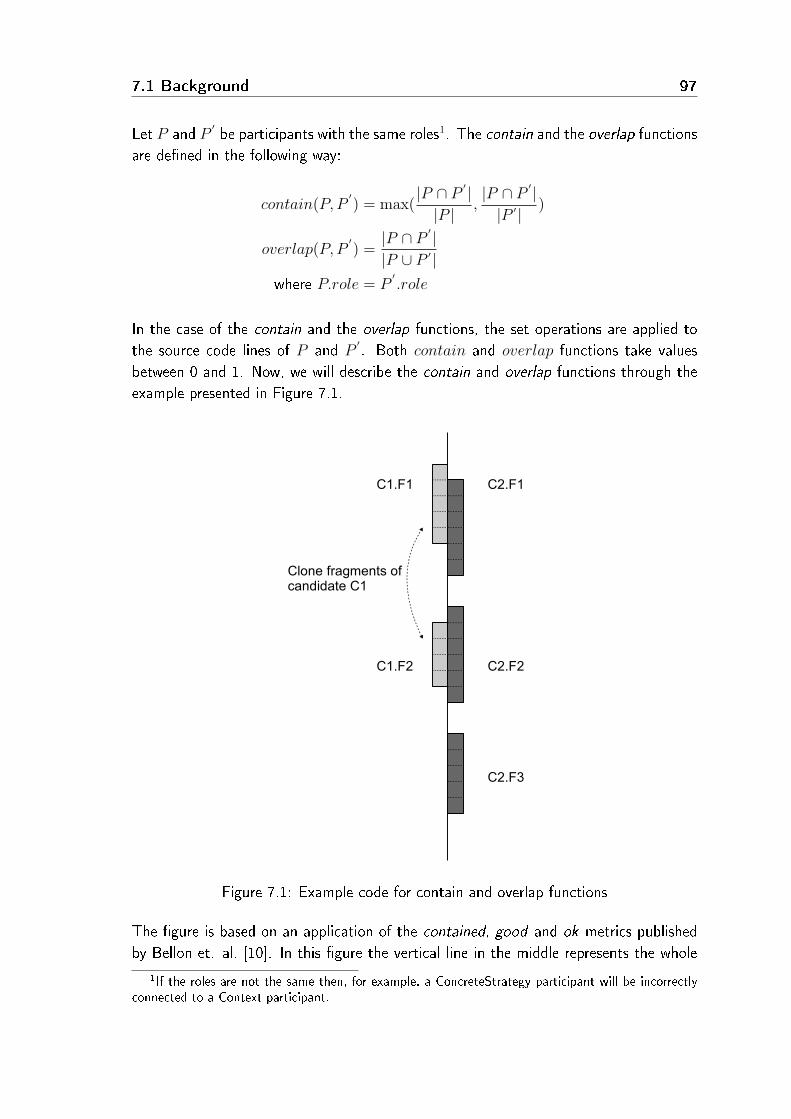
7.1 Background 97
Let P and P′be participants with the same roles1. The contain and the overlap functions
are de�ned in the following way:
contain(P, P′) = max(
|P ∩ P′|
|P |,|P ∩ P
′ ||P ′|
)
overlap(P, P′) =
|P ∩ P′|
|P ∪ P ′|where P.role = P
′.role
In the case of the contain and the overlap functions, the set operations are applied tothe source code lines of P and P
′. Both contain and overlap functions take values
between 0 and 1. Now, we will describe the contain and overlap functions through theexample presented in Figure 7.1.
Figure 7.1: Example code for contain and overlap functions
The �gure is based on an application of the contained, good and ok metrics publishedby Bellon et. al. [10]. In this �gure the vertical line in the middle represents the whole
1If the roles are not the same then, for example, a ConcreteStrategy participant will be incorrectlyconnected to a Context participant.

98 Validation of reverse engineering tools
source code linearly. The source code begins at the top of the vertical line and ends atthe bottom of the vertical line. The code fragments of the participants are representedby the �lled rectangles. Here, there are two clone candidates: C1 on the left hand sideand C2 on the right hand side. C1 has two cloned fragments (participant), C1.F1 andC1.F2, while C2 has three cloned fragments, C2.F1, C2.F2 and C2.F3. Subsequentsource code lines are separated by dashed lines inside the clone fragments, e.g. C1.F1
contains 5 lines of code. For example, in the case of C1.F1 and C2.F1, the functionsare calculated in the following way:
contain(C1.F1, C2.F1) = max(|C1.F1 ∩ C2.F1|
|C1.F1|,|C1.F1 ∩ C2.F1|
|C2.F1|)
= max(4
5,4
6) =
4
5= 0.8
overlap(C1.F1, C2.F1) =|C1.F1 ∩ C2.F1||C1.F1 ∪ C2.F1|
=4
7= 0.57
With matchp, either the contain or the overlap function is represented (exclusive or):
matchp(P, P′) = contain(P, P
′)⊕ overlap(P, P
′)
The matchpb function describes whether P and P′have a matchp above a prede�ned
bound :
matchpb(P, P′, bound) ={
1 if matchp(P, P′) >= bound
0 otherwise
With the use of the matchpb function, a matchi function can be de�ned between thecandidates. The matchi function denotes how many times matchpb returns one for eachparticipant of the C and C
′candidates:
matchi(C,C′, bound) =∑
P∈C
∑P
′∈C′
matchpb(P, P′, bound)

7.1 Background 99
Let us see how matchi is calculated in the case of the previous example. The �rst step isto calculate the selected function of matchp (either overlap or contain) for each possiblecombination of participants. Table 7.1 shows these values for C1 and C2. Afterwards,matchpb is calculated based on a prede�ned bound, which is 0.7 in this example. InTable 7.1 we denoted elements above this bound in bold. It means that matchpb isone in these cases, which is used in the calculation of matchi. In this way, we get thefollowing:
• In the case of matchp = contain, summarizing the matchpb values (in Table 7.1,bold values showing that matchpb is one) we �nd that matchi = 2
• In the case of matchp = overlap, each matchpb value is 0, so matchi = 0
Function Contain Overlap
P/P′
C2.F1 C2.F2 C2.F3 C2.F1 C2.F2 C2.F3
C1.F1 0.8 0 0 0.57 0 0C1.F2 0 1 0 0 0.67 0
Table 7.1: Contain and overlap values for the previous example
Minimal number of matching participants. Sometimes it is not enough to matchjust one participant between two candidates. For example, in the case of design patterns,the Abstract Factory pattern has two fundamental participants (mandatory roles), calledAbstract Factory and Abstract Product, for matching. For this reason, it is importantto determine the minimal number of common participants of two potential siblings. Letus denote the minimal number by m. The sibling relation between candidates C and C
′
with parameters m and bound is de�ned in the following way:
sibling(C,C′, bound,m) ={
true if matchi(C,C′, bound) >= m
false otherwise
The candidates can be grouped based on the sibling relation. A group contains can-didates that have a sibling relation in pairs. By using groups, the evaluation of thetools is more straightforward, and the statistical results are better than without it (seeSection 5.1.2 for a detailed discussion). In BEFRIEND, users can customize the siblingrelations by arbitrarily choosing between the contain and the overlap functions, givingthe bound and m parameters, and optionally selecting the roles for matching.
Continuing the previous example, let m = 1, matchp = contain and bound = 0.7.Besides these parameters, C1 and C2 are placed into the same group.

100 Validation of reverse engineering tools
Domain dependent name matching In certain domains, the roles are not so im-portant (e.g. code duplications have only one role called duplicated code). However, ifa domain contains several roles, some roles may be more important than the rest (as inthe case of the design pattern domain). For example, in the case of a Strategy designpattern, the Strategy participant determines a candidate and hence, the sibling relationshould be based on this participant. With such domains, the matchpb function has tobe modi�ed.
Let roles be a set that denotes the roles that are the basis of the sibling relations amongthe candidates. The matchpb is rede�ned as matchpb′ in these cases:
matchpb′(P, P′, bound, roles) ={
matchpb(P, P′, bound) if P.role ∈ roles
0 otherwise
In the case of domains where roles are important (e.g. design pattern miners), thematchpb function has to be replaced with matchpb′ in the formula of matchi.
Future extensions With the previous de�nitions, it is possible that a group containstwo or more candidates which are not siblings. Figure 7.2 shows an example of thisproblem. The previous example has been extended with one more candidate C3. In thisway, grouping candidates based on the original sibling relation means that C1 and C3are placed in the same group. As we do not allow such cases, the groups have to betransitive. Currently, in these cases the common candidates appear in each group. Inthe current example it means two groups: (C1, C2) and (C2, C3).
Overall, it may bias the statistics and the comparison because some candidates may berepeated across the groups (like C2). Therefore, this problem should be dealt with inthe future. A trivial solution for this problem is to apply di�erent grouping methods peruse case:
• In the case of manual evaluation, it is easier to evaluate related candidates togetherso a compliant grouping is enough. E.g. in the current example, it means onlyone group: (C1, C2, C3).
• Comparing candidates requires transitive, but not distinct groups. E.g. in thecurrent example it means two groups: (C1, C2) and (C2, C3).
• Calculating statistics requires transitive and distinct groups, E.g. in the example,it means three groups: (C1), (C2) and (C3).
At present, the benchmark supports the �rst strategy for each use case. However, itcould be easily extended with the two other approaches.

7.2 Use scenarios 101
Figure 7.2: Problem of the non-transitivity feature of the sibling relation
7.2 Use scenarios
Now we will show how the system works with the help of some scenarios graphicallyillustrated below. In each case, �rst we give a general description of its functionality,then we demonstrate its use with a concrete example. The examples are continuous, theyare built on each other, and they show how the benchmark is used. The �rst examplebegins with an empty benchmark without any kind of domain or evaluation criteria.
7.2.1 Setting up the database
In this scenario, we show how the user can create a new domain and evaluation crite-rion, how he can upload data in the system, and how he can set the sibling algorithmparameters. The functions that help one make the necessary settings can be found inthe Settings and Upload menus.

102 Validation of reverse engineering tools
Creating a new domain Now a new domain has to be created based on the datato be uploaded. For the creation of a new domain, the Domain settings panel must beused.
Figure 7.3: Creating a new domain
Example: We will upload the results of a duplicated code detecting tool. First, with thehelp of the Domain settings panel, we create a new domain which is called Duplicated
Code. As a result, the actual domain is set to the newly created Duplicated Code (seeFigure 7.3). If we have created more than one domain, we can select the domain wewould like to activate from the Select active domain drop-down list. The functionality ofBEFRIEND depends on and is performed on the active domain (e.g. querying candidates,evaluating candidates, statistics and comparison).
Creating new evaluation criteria In order to be able to evaluate the uploaded data,appropriate evaluation criteria are required. The user can create an arbitrary number ofcriteria per domains. On the basis of this, the uploaded candidates can be evaluated.In one evaluation criterion, one question has to be given to which an arbitrary numberof answers can be de�ned. Similar to the domain case, we can create a new criterionunder the Settings menu. When creating a new criterion, the following data should beentered:
• The title of the evaluation criterion (Title).
• The question related to the criterion (Question).
• The possible answers to the question (Choice). For each answer a percentage ratioshould be added to indicate to what extent the given question has been answered.Based on the replies by users, the benchmark can calculate di�erent statistics usingthis ratio.
• Should the precision and recall values be calculated? (Y/N)
Example: We will create an evaluation criterion called Correctness for the previouslycreated Duplicated Code domain. Enter a value of number 4 (meaning that we will havefour possible answers) in The number of choices within the created criteria �eld in theEvaluation criteria panel and click on the Create new criteria button. After �lling outthe form that appears and clicking on the Submit button, the criterion appears in the

7.2 Use scenarios 103
Figure 7.4: Correctness criteria
setting surface (see Figure 7.4). The Correctness criterion is used to decide to whatextent a code clone group comprises cloned code fragments. For the criterion, we alsohave to say whether the precision and recall values will be calculated or not.
During the evaluation, we will use two other criteria. One of them is Procedure abstrac-tion with the related question 'Is it worth substituting the duplicated code fragments
with a new function and function calls?' And the possible answers are:
• Yes, we could easily do that. (100%)
• Yes, we could do that with some extra e�ort. (66%)
• Yes, we could do that, but only with a lot of extra e�ort. (33%)
• No, it is not worth doing that. (0%)
With this, we de�ne how much e�ort would be needed to place the duplicated codefragments into a common function. The easier it is to introduce a function, the moreuseful the given candidate is on the basis of this criterion. This is an important indicatorbecause a tool that might not be able to �nd all the clones, but is able to �nd most ofthe easily replaceable ones is worth much more from a refactoring viewpoint.
The third criterion is Gain with the related question 'How much is the estimated gain of
refactoring into functions?' The possible answers are:
• The estimated gain is remarkable. (100%)
• The estimated gain is moderate. (50%)
• There is no gain at all. (0%)
It is important to evaluate how much bene�t would be gained by placing the codefragments into a function. It may happen that something is easily replaceable, but it isnot worth the trouble since no bene�t is gained by doing so.
Uploading data into the benchmark When the user has created the appropriatedomain and the required evaluation criteria, he has to upload the candidates produced

104 Validation of reverse engineering tools
Figure 7.5: Uploading data into BEFRIEND
by the tools to be evaluated. The upload page can be found in the Upload menu. Theformat of the �les to be uploaded is completely arbitrary, the only condition being thatthe evaluated tool should provide a BEFRIEND plug-in to perform the uploading. Thebenchmark provides a plug-in mechanism whereby implementing an interface the outputformat of any tool can be uploaded. Currently, the benchmark has plug-ins for the outputformats of the following tools: Columbus, CCFinderX, Simian, PMD and Bauhaus.
For uploading, the following data items are needed: the name of the tool and the nameand programming language of the software being analyzed. If an item was not presentearlier, we can add the new data to the list by selecting the New item option. Theuploaded data refer to a certain source code, so it is important to provide some kind ofaccess to these sources. Currently, the benchmark supports two access methods - httpand svn.
Example: Continuing the evaluation process, we upload the results produced by theclones command line program of the Bauhaus tool into the system. First, click on theUpload menu, which will take you to the upload page (see Figure 7.5). After giving therequired data and the path of the �le containing the results, click on the Upload buttonto perform the uploading.
Sibling setting Siblings allow candidates with similar properties to be handled to-gether during an evaluation (see Section 7.1.1). Settings can be applied in the Settingsmenu, on the Siblings settings panel (see Figure 7.6). The user can choose the Containor the Overlap function. In the Path matching bound �eld, the bound of the matchpb
relation should be between 0 and 100 (the matchp relation is projected into the interval0 to 100). In the Min. number of matching participants �eld, the number of participantswhose matching we need for two sibling candidates should be given (the m parameter

7.2 Use scenarios 105
of the sibling relation). Settings set by the user have to be saved in named con�gu-rations. Thus, if we wish to use an already saved setting in the future, we can load itby selecting it from the Load shortcut menu. In this case the system will not rerun thesibling grouping algorithm, but just reload the previously stored con�guration.
Figure 7.6: Sibling settings
Example: In the last part of the scenario, we set the sibling parameters (see Figure 7.6).For linking, we use the Contain function and the matching bound is set at 90%. Thereason for choosing this bound is that this way the candidates can be linked even in thecase of short code clones (10 lines). The ratio of the Min. number of participants to
match is 1, which means that it is enough to have two matching participants to link twoclone candidates. We save this con�guration as Moderate.
7.2.2 Data evaluation
The main task of the benchmark is to perform a visualization and evaluation of theuploaded data. In this section, we summarize what these functions do.
Query view The uploaded candidates can be accessed through the Evaluation menu.First, the Query view appears (see Figure 7.7), which helps the user de�ne the aspects,on the basis of which the uploaded candidates are listed. There are four possible aspects:Tool, Software, Language and the currently active domain (Design Pattern, DuplicatedCode or Rule Violation). The possible values of the aspects depend on the data of thealready uploaded candidates. For example, the Design Pattern aspect contains valueslike State or Adapter, while Tool contains values like Columbus when the active domainis Design Pattern.

106 Validation of reverse engineering tools
Figure 7.7: Query view
With more settings, even narrower candidate sets can be de�ned. If the user would liketo skip an aspect when �ltering, this aspect should be set to the None value. If he wouldlike to see all the items related to the selected aspects, the All value should be used.The order of the sequence of aspect selection is arbitrary. At the bottom of the queryview, there is a Connect siblings check box. If this box is marked, the candidates appearin groups, not individually.
Example: Select the Evaluation menu. The Query view page appears (see Figure 7.7). Inthe �gure, the �rst aspect is Software, whose value is set to JUnit4.1. The second aspectis Tool, whose value is All ; the third and fourth aspects are not used. We also activatedthe Connecting siblings check box. By clicking on the Go to results view button, we willget to the view of candidates satisfying the given aspects (see Figure 7.8).
Figure 7.8: Results view
Results view The columns of the table correspond to the aspects de�ned in the Queryview, with the exception of the last column. Here, the candidate identi�ers can be seen.By clicking on the identi�ers, the Individual instance view or the Group instance view
appears, depending on whether the user has set the grouping of siblings in the Query
view. Blue identi�ers represent a single candidate (or instance), while red identi�ersrepresent grouped candidates (or instances).
Example: In the �rst column of the table, JUnit4.1 can be seen based on the aspects setin the Query view (see Figure 7.8). Since all the tools were selected, the second column

7.2 Use scenarios 107
of the table contains every tool found in the database. The third column comprises theidenti�ers of the duplicated code candidates found by the tools. It can be seen that notall identi�ers are present in the table since we have set the grouping of siblings in theQuery view, so here the groups appear with the smallest candidate identi�ers.
Group instance view and Individual instance view The Instance view is used todisplay candidates and evaluate whether they are instances or not. BEFRIEND supportstwo kinds of instance views, namely Group instance view and Individual instance view.While the Group instance view can display multiple (grouped) candidates simultaneously,the Individual instance view displays the participants of only one candidate in each case.Apart from this di�erence, the two views are essentially the same.
In the Results view, the Instance view can be accessed by clicking on a candidateidenti�er. If the user has set the grouping of siblings in the Query view (see Figure 7.7),the system automatically applies the Group instance view. Otherwise, it applies theIndividual instance view.
Figure 7.9: Group instance view
Group instance view: The Participants table comprises the participants of the can-didates; the di�erent participants of all the siblings appear. The table has as many
108 Validation of reverse engineering tools
columns as the number of candidates in the group. Each column corresponds to a givencandidate whose identi�ers are indicated at the top of the column. In the intersection ofa row of participants and a column of candidates, either a green
√or a red × symbol
appears. The green√
means that the candidate in the given column comprises theparticipant in the row. The × symbol means that this particular candidate of the groupdoes not have such a participant. By clicking on the green
√with the right mouse
button, a pop-up menu appears, with the help of which the participant's source codecan be displayed. Whether the source code should be displayed on the left or right handside of the surface under the table can be selected from the menu. This is very usefulbecause, for instance, the participants of the duplicated code candidates lie next to eachother.
The evaluation criteria and, along with these, the voting user interface can be accessedby clicking on the 'Show criteria' link under the table of participants (see Figure 7.9).Statistics about previous votes of the candidates can be accessed by clicking on the statlink above the evaluation column. By moving the mouse above any of the green
√
symbols, a label appears with the source code name of the given participant (if it hasone). Comments can also be added to the candidates. A candidate can be commentedon by clicking on the candidate identi�er appearing above the Participants table. Thiswindow even contains information that reveals which tool found the given candidate.
Example: Click on candidate #31 in the Results view created in the previous example(see Figure 7.8). The Group instance view appears (see Figure 7.9). Right-click onany of the green
√symbols, and select Open to left in the appearing pop-up menu.
Right-click on another green√
symbol, and select Open to right in the menu. Thisway, the source code of two clone participants will be displayed next to each other.After examining the participants of all the four candidates belonging to this group, theevaluation criteria can be displayed by clicking on the 'Show criteria' link. Here, thecandidates can be evaluated.
Statistics view This view can be reached from the Query view by clicking on a linkother than a candidate identi�er. Here, relying on the structure seen in the Results
view, the user gets some statistics according to the evaluation criteria applied, based onthe previous user votes (see Figure 7.10). One table that comprises the vote statisticsfor all of the candidates concerned is associated with each evaluation criterion. In the�rst column of the table, the candidate identi�ers appear. The identi�er of the groupedcandidates is red, while that of the others is blue. Besides the identi�ers, �ve columnscan be found (mean, deviation, minimum, maximum and median) representing statisticsabout user votes for the corresponding candidate2. If we have decided in the Settings
2On the top of the statistics view the user can set the strategy of how to aggregate the votes of auser in the case of grouped candidates (red identi�ers): based on the average, maximum, minimum,deviation or median of the group candidate ratio. In the case of groups, these values (for each user)were used to calculate the statistics shown in Figure 7.10.

7.2 Use scenarios 109
menu that the precision and recall scores should be calculated, they will also appearunder the table corresponding to the criterion.
Figure 7.10: Bauhaus correctness statistics
Example: After having evaluated all the candidates found by the tools, we examine thestatistic we get for the votes of each tool. Let us go back from the Group instance view
(see Figure 7.9) to the Results view (see Figure 7.8) by clicking on the Back to previous
view link. Here, we get the statistical values of all the tools by clicking on 'JUnit4.1'.According to the 3 criteria, three tables belong to each tool. In the Correctness tableof the Bauhaus-clones tool, the statistics of the candidate votes can clearly be seen(see Figure 7.10). Furthermore, it can also be seen that some candidates are grouped,these being marked in red by the system. Underneath the table, information is providedlike precision and recall scores. The Number of instances above the threshold and Total
number of instances above the threshold are based on a setting at the top of the statisticsview. It is called the Threshold for calculating precision and recall, which by default is50%. This value determines which candidates can be accepted as instances (as truepositives). The �rst three items of information (starting with 'Number of') refer to theresults of the current tool, while the three items of information below Precision (startingwith 'Total number') refer to the results of all the tools examined.
On the basis of this data, precision and recall scores are automatically calculated. In thecase of Bauhaus the �rst is 62.79%, while the second is 84.38% .
Comparison view The system comprises yet another interesting view called the Com-parison view. In order to activate this view we have to start from a statistics view that

110 Validation of reverse engineering tools
comprises several tools. The comparison view compares the instances found by eachtool. For each possible coupling, it de�nes the instance sets found by two tools, and thedi�erence and intersection of these sets. This view allows us to compare the tools witheach other.
Figure 7.11: Comparison view
Example: In the Statistics view loaded in the previous example, click on the Switch to
comparison view and the Comparison view will appear (see Figure 7.11). A comparisonof tools is carried out in pairs, and here we also have the opportunity to link siblings inthe same way as in the other views (here the grouped instances are marked in red aswell).
7.3 Experimental results
Now we will summarize the results of the experiments performed using BEFRIEND.We should mention here that the aim of the experiment was the demonstration of the
capabilities of our system rather than the evaluation of the di�erent tools. During thedemonstration, �ve duplicated code �nder tools were assessed on two di�erent opensource projects, called JUnit and NotePad++. The tools used in the experiments wereBauhaus (clones and ccdiml), CCFinderX, Columbus, PMD and Simian.
Over 700 duplicated code candidates were evaluated by two developers. For the evalua-tion, three evaluation criteria were used, namely Correctness, Procedure abstraction andGain (see Section 7.2.1). The results of using the tools on the two open source projectsare shown in Table 7.2 and Table 7.3.
The precision and recall scores shown in the tables were calculated based on the Correct-ness criteria. In the rows of Procedure abstraction and Gain, the average values obtainedfrom the votes given for the candidates are shown according to the criteria applied. Weshould add that a threshold value is needed to calculate the precision and recall scores.

7.3 Experimental results 111
Criteria Bauhaus Columbus PMD Simianccdiml
Precision 100.0% 96.15% 62.5% 61.43%Recall 5.06% 28.09% 64.61% 48.31%Proc. abstr. 62.87% 65.59% 48.16% 48.12%Gain 55.95% 53.37% 33.88% 34.88%
Table 7.2: Results on NotePad++
The candidates above this threshold are treated as instances (see Section 7.2.2). Weused the default threshold value of 50%, but the threshold can be adjusted arbitrarily.For example, in the case of three voters, if two of them give 66% to a candidate, whilethe third one gives 33%, the average of the three votes is 55%. In such cases, it isreasonable to accept the candidate as an instance since two of the three voters acceptedit, while only one rejected it.
Criteria Bauhaus CCFinder Colum- PMD Simianclones bus
Precision 62.79% 54.84% 100.0% 100.0% 100.0%Recall 84.38% 53.13% 12.5% 15.63% 6.25%Proc. abstr. 48.31% 44.23% 79.0% 73.0% 66.25%Gain 29.36% 30.98% 62.5% 62.5% 62.5%
Table 7.3: Results on JUnit
CCFinderX is missing from Table 7.2 because it produced a huge number of hits withthe parameters we used (it found over 1000 duplicated code candidates containing atleast 10 lines). We were only able to evaluate the four other tools on NotePad++.
We learned some useful things during the evaluation. In the case of JUnit, PMD andSimian both produced a very similar result to Columbus's, but our experience is thatin general, the token based detectors (Bauhaus-clones, CCFinderX, PMD, Simian) pro-duce a substantially larger number of hits than the ASG based tools (Bauhaus-ccdiml,Columbus). This is partly due to the fact that while the ASG based tools �nd only thecandidates of at least 10 lines, which are also syntactically coherent, the token-baseddetectors mark the clones that are in many cases shorter than 10 lines and in such a waythat they expand the clone with several of the preceding and succeeding instructions (e.g.with '}' characters, indicating the end of the block). For example, a clone candidatecan mark the last line of a method and the �rst line of the subsequent method. Basedon this, the evaluation could be extended with a new criterion. The new criterion wouldapply to the accuracy of the marking of a clone candidate. It would also de�ne whatportion of the marked code is in the instance.
Based on the Gain and Procedure abstraction values of certain tools, we can say that theASG-based detectors �nd fewer but mostly more valuable and easily refactorable clone

112 Validation of reverse engineering tools
instances. In contrast, the token-based tools �nd more clone instances that produce amore complete result.
We should mention that we also imported the design pattern candidates from DEEBEEinto BEFRIEND. In addition to these, the system contains coding rule violation can-didates found by PMD and CheckStyle. In this way, BEFRIEND contains the resultsof three signi�cantly di�erent families (domains) of reverse engineering tools, namelyduplicated code detectors, design pattern miners and coding rule violation checkers.
7.4 Summary
We developed BEFRIEND from our benchmark for evaluating design pattern miner toolscalled DEEBEE. During the development of BEFRIEND, we tried to generalize it in everyway possible, e.g. an arbitrary number of domains can be created, domain evaluationaspects and the settings of candidate siblings can be customized. To upload the resultsof di�erent tools, the benchmark provides a plug-in mechanism. We applied BEFRIENDto three reverse engineering domains, namely design pattern mining tools, code clonemining tools, and coding rule violation checking tools. The evaluation results stored inDEEBEE were migrated to BEFRIEND, and in the code clones domain we applied thebenchmark using more examples. The sibling mechanism of DEEBEE was also improvedto support other domains as well.
The work done here is the �rst step towards creating a generally applicable benchmarkthat can help one to evaluate and compare many kinds of reverse engineering tools. Inthe future, it would be good to get the opinions and advice of reverse engineering tooldevelopers about our benchmark to achieve and satisfy all their needs. BEFRIEND isfreely available to the public via the link http://www.inf.u-szeged.hu/befriend/


Chapter 8
Conclusions
�In all human a�airs there are e�orts, and there are results,and the strength of the e�ort is the measure of the result.�
James Allen
The maintainability of (legacy) software systems usually becomes increasingly di�cultafter several releases of the system. It may be caused by the fact that important partsof the software development process were left out because of strict deadlines. Thesephases typically include the speci�cation of the system, designing the system architectureand testing the deliverables. However, legacy systems provide important, valuable andfrequently irreplaceable functionalities, hence the system has to be recovered. Rewritingthe system from scratch is costly, time consuming, and there is a big chance of failure.In contrast, reengineering the system in small steps is relatively cheap and safe. Thesuccess of reengineering largely depends on the reverse engineering phase. Reverseengineering provides high level information about the source code, e.g. in the form ofdesign patterns, coding rule violations and duplicated code fragments. The problemis that these tools sometimes produce false positives, which might lead to the overallfailure of the whole reengineering project. In this thesis we provided techniques, tools andexperiments for improving, evaluating and comparing the performance and correctnessof reverse engineering tools.
First, we proposed a machine learning�based approach to improve the results of ourdesign pattern miner tool. We extended the architecture of the Columbus frameworkand integrated machine learning tools. Experiments were also performed on a real�lifesoftware system to demonstrate the feasibility of our approach.
Next, we evaluated and compared three design pattern miner tools called Columbus,Maisa and CrocoPat. These tools were evaluated in terms of speed, memory consumptionand the di�erences between the candidates. In the case of CrocoPat, the necessaryColumbus plugin was also developed to generate the input for the tool. Furthermore,the corresponding pattern de�nitions in its own pattern description language (RML) werede�ned by us.
In the next part, an online benchmark (DEEBEE) for evaluating and comparing designpattern miner tools was presented. In this study, based on the results of Chapter 4, the
115
116 Conclusions
grouping of similar candidates was introduced to provide reliable statistics and compar-isons. Experiments were also performed to demonstrate the capabilities of the bench-mark. Then the benchmark was evaluated based on the requirements de�ned by Sim etal. [74].
We made the CSV format of DEEBEE as simple as possible, but it became insu�cientlyexpressive. Furthermore, we found that formats of design pattern miner tools had certainde�ciencies or problems. Based on this motivation, a common exchange format wasproposed in Chapter 6. First, we de�ned requirements for the format, and then, takinginto account the requirements, we elaborated on the metamodels of the format. Theformat was implemented in XML, based on the entities and relations de�ned in themetamodel.
In Chapter 7 we introduced BEFRIEND, a benchmark for reverse engineering tools.BEFRIEND is based on DEEBEE and is a fully generalized version of it. First, it supportsthe evaluation and comparison of di�erent kinds of reverse engineering tools via domains.BEFRIEND supports arbitrary evaluation criteria for each tool domain. It also handlesand groups similar candidates based on a generalized sibling relation. The benchmarkuser interface was also applied on real-life examples.
There are several ways our work might be extended in the future. For example, notingthe �rst thesis point, the proposed machine learning based improvement method couldbe adapted to other kinds of reverse engineering tools (e.g. bad code smell [36] miners).As for the benchmarks presented(DEEBEE and BEFRIEND), other case studies andnew reverse engineering domains could be introduced like that done in the area ofchange impact analysis tools [85]. In addition, benchmarks could support performancemeasurement information as well. The DPDX format might be extended in di�erentways. For instance, it could be compared with other approaches (e.g. GXL) or itcould be evaluated and improved through the collaboration of design pattern miner toolcreators.

117


Appendix A
Related Work
A.1 Design pattern mining
One of the �rst studies in this topic is the one describing the BACKDOOR (BackwardsArchitecting Concerned with Knowledge Discovery of OO Relationships) [71] inductivemethod. The method provides guidelines for analyzing existing object-oriented softwaresystems and reverse architecting design patterns. The crucial part of the method is theanalysis of design pattern candidates, namely to select the characteristics that properlyidentify them. This is the most human-intensive part. The purpose of this part is tocompare the potential patterns found against the set of reference patterns. The basisof the comparison is not only their structure but also their semantics. The patterncandidates were classi�ed according to their correspondence with the reference designpatterns. One aspect of the classi�cation was the implementation and another wasthe purpose. The measures of a classi�cation are complete match and partial match,thus they have a four level classi�cation of possible patterns. The technique permitsthe creation of a pattern knowledge base whose main purpose is to help developmentorganizations create their own custom pattern library.
Kaczor et al. [50] proposed a bit-vector algorithm for design pattern identi�cation. Thealgorithm initialization step converts the design pattern motif and the analyzed programmodel into strings. To model the design patterns and the analyzed program, six pos-sible relations can be used between elements: association, aggregation, composition,instantiation, inheritance and dummy. The authors gave an e�cient Iterative Bit-vectorAlgorithm to match the string representation of the design patterns and the analyzedprogram. They compared their implementation with explanation-based constraint pro-gramming and metric-enhanced constraint programming approaches.
Costagliola et al. [22] based their approach on a visual language parsing technique. Thedesign pattern recognition was reduced to recognizing sub-sentences in a class diagram,
119

120 Related Work
where each sub-sentence corresponds to a design pattern speci�ed by an XPG grammar.Their process consist of two phases: the input source code is translated into a classdiagram represented in SVG format; then DPRE (Design Pattern Recovery Environment)recovers design patterns using an e�cient LR-based parsing approach.
Tonella and Antoniol [82] presented an interesting approach to recognize design patterns.They did not use a library of design patterns as others did but, instead, discoveredrecurrent patterns directly from the source code. They employed concept analysis [72]to recognize groups of classes sharing common relations. The reason for adapting thisapproach was that a design pattern could be considered as a formal concept. They usedinductive context construction which then helped them to �nd the best concept.
Albin-Amiot et al. [1] introduced a Pattern Description Language (PDL) that was suitablefor detecting design patterns from source code and also for generating source code. Theirsystem was also able to detect some distorted versions of design patterns and could repairthem automatically with the aid of a source-to-source transformation engine.
Keller et al. [52] argued that design patterns form the basis of many of the key elementsof large-scale software systems, so to comprehend these systems they needed to recoverand understand design patterns. They emphasized not only the design's structure, butits rationale too. They utilized the SPOOL environment which provided tools for ana-lyzing existing source code and recovering design components like design patterns. Theyimplemented query mechanisms that could recognize the structural descriptions of pat-terns in the source code models. The SPOOL environment gave some visual informationabout the query's results (the design patterns found) and information about the designpattern's class diagram to discover the pattern's structure and documentation about itsintent and motivation. They used this environment with three industrial systems andsearched for three design patterns (Template Method, Factory Method and Bridge).They checked the intent of the design patterns found and noticed that the discovereddesign patterns' intents did not necessarily correspond to the original design patterns'intents.
Asencio et al. [6] used the Imagix [45] tool to parse the source code. The tool builta database of program entities and relationships. They introduced a recognizer spec-i�cation language where they made declarative speci�cations � logical conditions � todescribe design pattern structures. Afterwards, their tool called Osprey automaticallygenerated Python source code from these declarative speci�cations, which searched pat-terns in the database generated by Imagix. They tested their system on several softwaresystems and obtained promising results, but also found false positives. They classi�edthe causes of these false hits. The �rst class of problems were the front end analyzererrors. The second class was the pattern ambiguity. The cause of these false hits werethe structural similarities among design patterns, like those of the Decorator and Proxypatterns. The third class of problems were the partial patterns. Actually, there weremany situations where the full pattern was not present in the code.

A.2 Improvement of design pattern mining 121
Campo et al. [18] utilized design pattern recognition for framework comprehension. Theyconcluded that some design patterns could be distinguished only by their dynamic be-haviour, because their structures were the same (e. g. Composite vs. Decorator andState vs. Strategy).
A.2 Improvement of design pattern mining
The accuracy of design pattern discovery has been improved by some researchers usingdynamic analysis which, apart from the structural information, also considers runtimeinformation of the system in question [89, 90]. First, the author performed a staticanalysis and labeled each pattern candidate with a fuzzy value that represented thecorrectness of the candidate. Afterwards, false candidates were ruled out by dynamicanalysis and by using these fuzzy values.
Guéhéneuc et al. [44] introduced a method for reducing the search space for designpatterns. First, they analyzed several programs manually and searched for source classesthat act together as design patterns and set up a repository from them. Afterwards, theyparsed these programs with tools to obtain models of their source code, and computedmetrics from these models (like size, cohesion and coupling). In the next step theyran their rule learner algorithm that returned a set of rules characterizing the designpattern participants by the metric values. This way, they obtained rule sets (called a�ngerprint) for the participant classes of the design patterns. Based on these �ngerprints,unknown classes were characterized. They then integrated this �ngerprint technique intotheir constraint-based tool suite to reduce the search space. Their work is in some sensesimilar to ours, but we made use of machine learning after the structural matching phase(taking into consideration the whole design pattern and not just individual classes) to�lter out false candidates.
Antoniol et al. introduced pattern recognition by using metrics [4]. They analyzed sourcecode and class diagrams and created AOL (Abstract Object Language) speci�cationscontaining information about classes, their members and relations. The design patterndescriptions were also stored in AOL format. Next, they created an AST (AbstractSyntax Tree) from the AOL speci�cation. Afterwards, they computed metrics for eachcandidate class from the AST and created a set for each participant class in the searcheddesign pattern containing only those candidate classes which met the participant classes'metric conditions (these conditions were set up manually). This way, they signi�cantlyreduced the search space. Next, they checked the required structural relations amongthe candidate classes in these sets. They were also able to verify the consistency betweenthe code and the design. They then tested their system on public and industrial systemsand got good results.

122 Related Work
As we mentioned previously, a lot of e�ort has gone into improving the design patternmining process. The approaches focus on two aspects of the design pattern miningprocess, namely
• improving the results in the last step of the process via a dynamic analysis
• reducing the search space by incorporating some human knowledge into the process
A.3 Evaluation of reverse engineering tools
Sim et al. [74] collected the most important aspects, properties and problems of bench-marking in software engineering. They argued that benchmarking has a strong positive
e�ect on research. They gave a de�nition for benchmarking: �a test or set of testsused to compare the performance of alternative tools or techniques.� A benchmark haspreconditions. First, there must be a minimum level of maturity of the given researcharea. Second, it is desirable that diverse approaches exist. The authors de�ned sevenrequirements of successful benchmarks, namely accessibility, a�ordability, clarity, rele-vance, solvability, portability and scalability. Sim gives a more detailed description andexamples in her PhD thesis [73].
Nowadays, more and more papers deal with the evaluation of reverse engineering tools.These are needed because the number of reverse engineering tools is increasing and it isdi�cult to decide which of these tools is the most suitable for a given task.
Evaluation of design pattern mining tools
Petterson et al. [63] summarized problems during an evaluation of accuracy in patterndetection. The goal was to make accuracy measurements more comparable. Six majorproblems were revealed: design patterns and variants, pattern instance type, exact andpartial match, system size, precision and recall, and the control set. A control set was�the set of correct pattern instances for a program system and design pattern.� Thedetermination of the control sets is very di�cult, hence solutions taken from naturallanguage parsers were considered. One good solution is tree banks. Tree banks couldbe adapted by establishing a large, manually validated pattern instances database. An-other adaptable solution is that of a pooling process: �The idea is that every system
participating in the evaluation contributes a list of n top ranked documents, and that
all documents appearing on one of these lists are submitted to manual relevance judge-
ment.� The process of constructing control sets has the following problems. They arenot complete in most software systems, and in a real-life software system a single groupis not able to determine a complete control set. They stated that a community e�ort is
required to make control sets for a given set of applications.
A.3 Evaluation of reverse engineering tools 123
Guéhéneuc et al. [43] introduced a comparative framework for design recovery tools.The purpose of the authors' framework was not to rank the tools, Ptidej (Pattern TraceIdenti�cation, Detection, and Enhancement in Java [65]) and LiCoR (Library for CodeReasoning [55]), but to compare them on the basis of their qualitative aspects. Thisframework contained eight aspects called context, intent, users, input, technique, output,implementation and tool. There is a major need for such a framework since making acomparison among the several design recovery tools is very di�cult due to the fact thatthey have quite di�erent characteristics in terms of representation, output format andimplementation techniques. This framework provides an opportunity for comparing notonly similar systems, but also systems which are di�erent. Our study is di�erent from thisone because we used a benchmark to evaluate design pattern instances and to comparedesign pattern miner tools based on their results.
Dong et al. [30] introduced a systematic review of design pattern mining techniques.The authors presented a comparative study on di�erent aspects of several approachesof design pattern mining. These aspects include the type of the algorithm applied(structural, behavioural, etc.) and supported programming languages (C++, Java, etc.),system representation (AST, matrix, etc.). Furthermore, the authors found that di�erentapproaches yield di�erent results, and they collected the possible reasons for this, likemissing roles, role types, missing relationships, delegation implementations and mergingroles. In this sense, this work is similar to that presented in Chapter 4, but it waspublished later.
Arcelli et al. [5] proposed three categories for design pattern mining tools, consideringthe information which was used during the detection process. These categories are the�entire� representation of design patterns, the minimal set of key structures that a designpattern consists of, and the sub-components of design patterns. They dealt with thelast category, and two tools for this called FUJABA and SPQR were introduced andcompared. The basis of the comparison was how a tool decomposes a design patterninto smaller pieces. The conclusion was that the decomposition methods of the twoexamined systems are very similar, and after they argued the bene�ts of sub-patterns.
P-MARt, an XML-based repository of micro-architectures similar to design patterns, wasintroduced by Guéhéneuc [40]. In each session, he asked students to analyse a new systemand detect design patterns manually. Furthermore, he collected micro-architectures fromhis colleagues as well. The micro-architectures are stored in a XML �le.
Evaluation of other reverse engineering tools
Bellon et al. [10] performed an experiment to evaluate and compare clone detectors. Theexperiment involved several researchers who applied their tools on carefully selected largeC and Java programs. The comparison shed light on some facts that were previously

124 Related Work
unknown, so both the strengths and the weaknesses of the tools were discovered. Theirbenchmark provides a standard procedure for every new clone detector. Bellon alsopublished a publicly available benchmark [11].
Rysselberghe et al. [69] compared di�erent clone searching techniques (string, token andparse tree-based). For the sake of comparison, they developed reference implementa-tions of the di�erent techniques instead of using existing tools. During their evaluation,they asked certain questions, some of which correspond to the criteria introduced in BE-FRIEND. One such question was 'How accurate are the results?' The di�erent techniqueswere tested on �ve small-and medium-sized projects by using the evaluating questions.In another article, they compared the reference implementations of the clone search-ing techniques based on refactoring aspects [68]. These aspects were called suitable,relevance, con�dence and focus.
Burd et al. [17] evaluated �ve clone searching tools on the university project calledGraphTool. They also examined the problem of how to link the instances. For thisreason, they used a simple overlap method. In the evaluation part, they applied thewell-known precision and recall scores approach. In addition, they presented di�erentstatistics and comparison mechanisms, some parts of which are even now supported byBEFRIEND (e.g. intersection and di�erence of the results).
Wagner et al. [88] compared three Java bug searching tools on one university and �veindustrial projects. A 5-level severity scale, which can be integrated into BEFRIEND,served as the basis for comparison. Based on this scale, 'Defects that lead to a crash of
the application' is the most serious one, while 'Defects that reduce the maintainability
of the code' is the least serious one. The tools were compared not only with each other,but with reviews and tests as well. We should mention here both the reviews and thetests can be loaded into BEFRIEND by writing the appropriate plug-ins. In two otherarticles [86, 87] they also examined the performance of bug searching tools.
Ayewah et al. [7] evaluated the FindBugs tool on three large scale projects called SUNJDK 1.6, Google and GlassFish. During the evaluation they applied the following cate-gories in the case of JDK 1.6: Bad analysis, Trivial, Impact and Serious.
Rutar et al. [67] evaluated and compared �ve tools called FindBugs, JLint, PMD, Ban-dera and ESC/Java. The evaluation was carried out on �ve projects (Apache Tomcat5.019, JBoss 3.2.3, Art of Illusion 1.7, Azureus 2.0.7 and Megamek 0.29). They ob-served that the rate of overlap among the tools was very low and the correlation amongthe hits of the tools was weak. This led them to conclude that rule violation searchingtools de�nitely require an evaluation and comparison tool like BEFRIEND.
Sim et al. [75] developed the CppETS benchmark to evaluate C++ extractors. Thebenchmark used two categories, namely accuracy and robustness. It consisted of 25test cases, 14 in the accuracy and 11 in the robustness category. The test cases were

A.3 Evaluation of reverse engineering tools 125
typically less than 100 lines of code long, and none contained more than 1000 lines.They measured the performance by asking questions in a text �le in all test cases. Thesequestions have to be answered by the persons using the extractor. They evaluated fourextractors called Ccia, cppx, Rigi and TkSee/SN.
Sim et al. [76, 77] described a live demonstration of program comprehension tools.Five software development teams were involved in this demonstration, namely Lemma,PBD, Rigi, TkSee and Visual Age C++. UNIX Tools such as grep and emacs were alsodemonstrated because of their popularity. The tools had to solve two reverse engineeringand three maintenance tasks on the x�g drawing package. Afterwards, they collectedthe results of the tools and closed with a discussion of observations. They mentionedthat 'the biggest di�culty for some teams was parsing the source code.' This is a seriousproblem in design pattern mining too, so it is vital that the extracted facts about thesource code are correct.
We already have some experience in developing a benchmark. The o�cial code sizebenchmark for the GCC compiler called CSiBE [12, 23] is the result of our previous work(see http://gcc.gnu.org/benchmarks/). The primary purpose of CSiBE is to monitorthe size of the code generated by GCC. In addition, the compilation time and the codeperformance measurements are also provided.


Appendix B
DPDX
B.1 Output formats of DPD tools
To emphasize the similarities and di�erences all formats are presented using the ex-ample of the `Decorator' instance taken from Java IO, illustrated in Figure 6.10 (seeSection 6.3.3). This is also done for tools that cannot analyze Java programs (likeColumbus) or do not try to detect instances of the `Decorator' pattern (like Fujaba).In such cases, we showed what the format would look like if the tool supported the`Decorator' pattern mining from Java source code. In addition, we also reviewed theresult representation format used by two DPD result repositories, namely P-MARt [61]and DEEBEE [97].
1<pattern name="Decorator">
2 <role name="Component">"Writer"</role>
3 <role name="Decorator">"Bu�eredWriter"</role>
4 <role name="ConcreteComponent">"OutputStreamWriter"</role>
5 <role name="ConcreteDecorator">"CharCountBu�eredWriter"</role>
6 <role name="operation">"close"</role>
7</pattern>
Figure B.1: Output format of SPQR
INSTANCE Component ConcreteComponent Decorator ConcreteDecorator
Decorator[0] Writer OutputStreamWriter Bu�eredWriter CharCountBu�eredWriter
Decorator[0] Writer OutputStreamWriter Bu�eredWriter BlackListBu�eredWriter
Table B.1: DP-Miner result
127

128 DPDX
1<StructuralAnnotation name="Decorator"
2 fuzzyBelief="56.6666666666664">
3 <BoundObject key="Component" name="java.io.Writer"/>
4 <BoundObject key="Decorator" name="java.io.Bu�eredWriter"/>
5 <BoundObject key="operation" name="write(char[],int,int)"/>
6</StructuralAnnotation>
Figure B.2: Output format of Fujaba
Solution 0
Component = Writer
Component.Operation() = Writer.close()
Decorator = Bu�eredWriter
Decorator.Operation() = Bu�eredWriter.close()
Decorator.component = Bu�eredWriter.out
ConcreteComponent = OutputStreamWriter
ConcreteComponent.Operation() = OutputStreamWriter.close()
ConcreteDecorator = CharCounterBu�eredWriter
ConcreteDecorator.Operation() =
CharCounterBu�eredWriter.close()
ConcreteDecorator.AddedBehavior() =
CharCounterBu�eredWriter.extendStream()
Figure B.3: Output format of Maisa
1<pattern name="Decorator">
2 <instance>
3 <role name="Component" class="java.io.Writer"/>
4 <role name="Decorator" class="java.io.Bu�eredWriter"/>
5 </instance>
6</pattern>
Figure B.4: Output format of SSA

B.1 Output formats of DPD tools 129
Source class(es) for pattern class Component:
/src/Writer.java(50): pattern class Component =
source class Writer
/src/Writer.java(323): pattern operation Operation =
source operation close
Source class(es) for pattern class ConcreteComponent:
...
Source class(es) for pattern class Decorator:
...
Source class(es) for pattern class ConcreteDecorator:
Figure B.5: Output format of Columbus
Decorator Pattern.
Writer is the Decoratee class.
Bu�eredWriter is the Decorator class.
Concrete Decorator classes:
CharCounterBu�eredWriter BlackListBu�eredWriter
�ush() is the decorate operation
Files Location:
java/io/Writer.java, java/io/Bu�eredWriter.java
Figure B.6: Output format of PINOT
Decorator : 100%
component as java.io.Writer ,
concretecomponent-1 as java.io.FileWriter ,
concretecomponent-2 as java.io.ObjectWriter ,
decorator as java.io.Bu�eredWriter ,
concretedecorator-1 as java.io.CharCounterBu�eredWriter ,
concretedecorator-2 as java.io.BlackListBu�eredWriter
Figure B.7: Output format of Ptidej
Decorator
class AbstractClass,Writer,Writer.java:1:6
operation �ush,Writer,Writer.java:3:15
class ConcreteClass,Bu�eredWriter,Bu�eredWriter.java:8:12
operation �ush,Bu�eredWriter,Bu�eredWriter.java:9:9
Figure B.8: Input format of DEEBEE
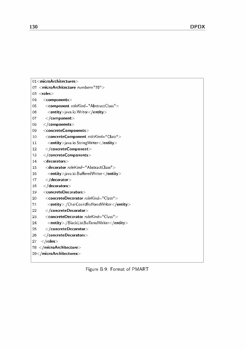
130 DPDX
01<microArchitectures>
02 <microArchitecture number="76">
03 <roles>
04 <components>
05 <component roleKind="AbstractClass">
06 <entity>java.io.Writer</entity>
07 </component>
08 </components>
09 <concreteComponents>
10 <concreteComponent roleKind="Class">
11 <entity>java.io.StringWriter</entity>
12 </concreteComponent>
13 </concreteComponents>
14 <decorators>
15 <decorator roleKind="AbstractClass">
16 <entity>java.io.Bu�eredWriter</entity>
17 </decorator>
18 </decorators>
19 <concreteDecorators>
20 <concreteDecorator roleKind="Class">
21 <entity>./CharCountBu�eredWriter</entity>
22 </concreteDecorator>
23 <concreteDecorator roleKind="Class">
24 <entity>./BlackListBu�eredWriter</entity>
25 </concreteDecorator>
26 </concreteDecorators>
27 </roles>
28 </microArchitecture>
29</microArchitectures>
Figure B.9: Format of PMART

B.2 DPDX attribute values 131
B.2 DPDX attribute values
In order to make our DPDX format really useful, the tools (and people) using theformat must agree on a standard terminology for keywords applied in DPDX. This isimportant because XML attributes are just strings, but we need a special meaning forsome strings (e.g. the relation name cannot be an arbitrary string but a discrete valuefrom a known relation types set). So it is essential that all users of the format usethe same keyword for describing the same concept. Otherwise the primary aim of thecommon exchange format, namely to make the design pattern candidates comparable,would be lost. For this very reason we would suggest that all researchers interested inusing (or even developing) DPDX should use our publicly available WIKI page [92] asa primary source of the existing DPDX attribute values. Each researcher is welcome toextend the available keywords if there is no suitable one available. This page preventsus from using di�erent keywords with the same meaning; moreover the introduction ofnew keywords would be based on a common consensus.
As an example, we collected a reference list of possible keywords used as attribute valuesin DPDX, which is presented in tables B.2, B.3 and B.4.
Tag name Attribute name Possible attributevalues
`Role' `kind' Class, Method, Field,Call
`Property' `name' abstractness, visibilitystaticness
`Relation' `relationName' subtypeOf, hasType,invokes
Table B.2: Attribute values of DPDX
Each property tag with a di�erent name attribute has a di�erent set of possible kind
values. These values are listed in Table B.3.
Property name Propertyattribute
Possible attribute values
abstractness `kind' abstract, interface, concretevisibility `kind' public, protected, privatestaticness `kind' static, non-static
Table B.3: Property values
Table B.4, which summarizes the possible values for program element kinds and names,is organized somewhat di�erently. The reason for this is that there are semantic depen-dencies between program elements.

132 DPDX
The �rst column of the table shows the possible values for the `kind' attribute of aprogram element (note that program elements are `NamedElement', `TypedElement',`IndexedElement', `Block' and `ReferencingStatement'). The second column shows thepossible program element names within this kind of element. The third column containsa brief description of which element is denoted by the second column.
The listed values are language independent, although the keywords used in the tablesfollow the Java terminology. We prefer this solution instead of creating a whole newterminology. We chose Java for the base language because of its current popularity.Despite the equivalence in terminology, our keywords have a more general meaning.They can be interpreted for various di�erent programming languages. For example, theproperty value abstract (which is a Java keyword) can be used in DPDX to describe C++design pattern candidates as well. We have di�erent interpretations of the keywords fordi�erent languages; e.g. the abstract property of a Java class means the class is de�nedusing the abstract Java keyword, but in the case of a C++ class, it means that the classhas at least one pure virtual method (but not all of them are pure virtual as this wouldmake the class an interface).

B.2 DPDX attribute values 133
Program elementkind
Possible child nodename
Denoted element
class, �eld, method body (implicit) �eld initializer, classinitializer or body of method
invocation target the expression denoting theobject on which the method
is invokedcall the invocation expression
itselfget target the expression denoting the
object whose �eld isaccessed. The value �this�denotes the object for which
the current method isexecuting
�eld the expression denoting theaccessed �eld
set target the expression denoting theobject whose �eld is
accessed. The value �this�denotes the object for which
the current method isexecuting
�eld the expression denoting theaccessed �eld
value the expression denoting thenew value of the �eld
conditional if conditionthen �rst alternativeelse second alternative
switch switch switch expressioncases a block of blocks, each
representing a di�erent case.Individual cases are identi�edby their index within this
blockwhileloop, dowhileloop,
dountillooploopcondition condition
loopbody loop bodyforloop forinit
forincrementforconditionforbody
Table B.4: Program element hierarchy

134 DPDX
B.3 DPDX implementation examples
Figures B.10, B.11, B.12 and B.13 show the implementation of DPDX.
01<PatternSchema id ="PS1" name="Decorator" variantOf="%NONE%">
02 <Roles>
03 <Role id="R1" name="Component" kind="Class" cardinality="1">
04 <Property name="abstractness" value="abstract" strict="false"/>
05 <Role id="R2" name="Operation" kind="Method" cardinality="+"/>
06 </Role>
07 <Role id="R3" name="Decorator" kind="Class" cardinality="1">
08 <Role id="R4" name="Forwarder" kind="Method" cardinality="+">
09 <Role id="R5" name="ForwardCall" kind="Call" cardinality="1"/>
10 </Role>
11 <Role id="R6" name="Parent" kind="Field" cardinality="1"/>
12 </Role>
13 <Role id="R7" name="ConcreteDecorator" kind="Class" cardinality="*">
14 <Property name="abstractness" value="concrete" strict="true"/>
15 </Role>
16 </Roles>
17
18 <Relations>
19 <Relation id="RE1" name="subTypeOf" source="R3" srcCard="1"
20 target="R1" targetCard="1" mandatory="true" direct="false"/>
21 <Relation id="RE2" name="subTypeOf" source="R7" srcCard="1"
22 target="R3" targetCard="1" mandatory="false" direct="false"/>
23 <Relation id="RE3" name="invokes" source="R5" srcCard="1"
24 target="R2" targetCard="1" mandatory="true" direct="true"/>
25 <Relation id="RE4" name="hasType" source="R6" srcCard="1"
26 target="R1" targetCard="1" mandatory="true" direct="false"/>
27 </Relations>
28</PatternSchema>
Figure B.10: Implementation of the schema metamodel
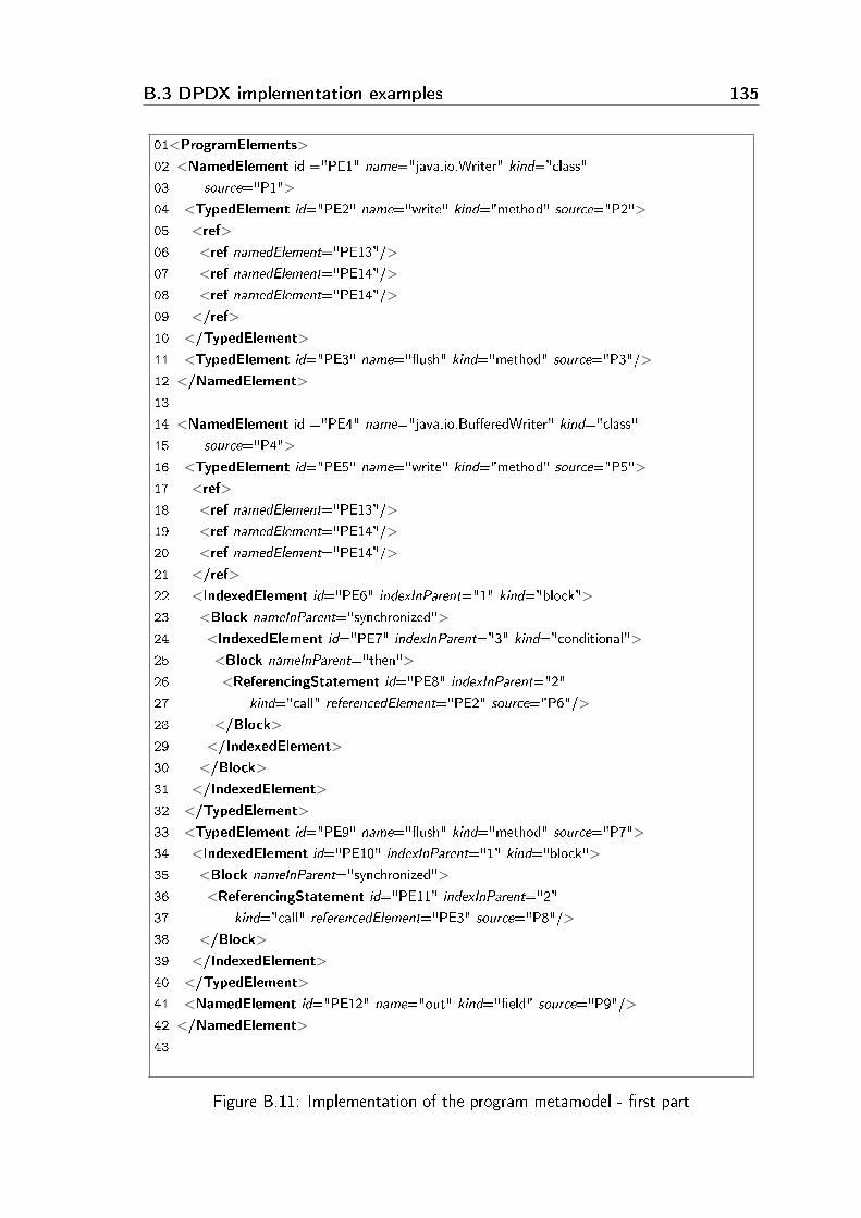
B.3 DPDX implementation examples 135
01<ProgramElements>
02 <NamedElement id ="PE1" name="java.io.Writer" kind="class"
03 source="P1">
04 <TypedElement id="PE2" name="write" kind="method" source="P2">
05 <ref>
06 <ref namedElement="PE13"/>
07 <ref namedElement="PE14"/>
08 <ref namedElement="PE14"/>
09 </ref>
10 </TypedElement>
11 <TypedElement id="PE3" name="�ush" kind="method" source="P3"/>
12 </NamedElement>
13
14 <NamedElement id ="PE4" name="java.io.Bu�eredWriter" kind="class"
15 source="P4">
16 <TypedElement id="PE5" name="write" kind="method" source="P5">
17 <ref>
18 <ref namedElement="PE13"/>
19 <ref namedElement="PE14"/>
20 <ref namedElement="PE14"/>
21 </ref>
22 <IndexedElement id="PE6" indexInParent="1" kind="block">
23 <Block nameInParent="synchronized">
24 <IndexedElement id="PE7" indexInParent="3" kind="conditional">
25 <Block nameInParent="then">
26 <ReferencingStatement id="PE8" indexInParent="2"
27 kind="call" referencedElement="PE2" source="P6"/>
28 </Block>
29 </IndexedElement>
30 </Block>
31 </IndexedElement>
32 </TypedElement>
33 <TypedElement id="PE9" name="�ush" kind="method" source="P7">
34 <IndexedElement id="PE10" indexInParent="1" kind="block">
35 <Block nameInParent="synchronized">
36 <ReferencingStatement id="PE11" indexInParent="2"
37 kind="call" referencedElement="PE3" source="P8"/>
38 </Block>
39 </IndexedElement>
40 </TypedElement>
41 <NamedElement id="PE12" name="out" kind="�eld" source="P9"/>
42 </NamedElement>
43
Figure B.11: Implementation of the program metamodel - �rst part

136 DPDX
44 <NamedElement id="PE13" kind="basicType" name="char[]"/>
45 <NamedElement id="PE14" kind="basicType" name="int"/>
46
47 <Sources>
48 <Source id="P1" URI="/java/io/Writer.java" line="33" col="1"
49 endLine="308" endCol="1"/>
50 <Source id="P2" URI="/java/io/Writer.java" line="128" col="5"
51 endLine="128" endCol="81"/>
52 <Source id="P3" URI="/java/io/Writer.java" line="293" col="5"
53 endLine="293" endCol="52"/>
54 <Source id="P4" URI="/java/io/Bu�eredWriter.java" line="47"
55 col="1" endLine="253" endCol="1"/>
56 <Source id="P5" URI="/java/io/Bu�eredWriter.java" line="154"
57 col="5" endLine="183" endCol="5"/>
58 <Source id="P6" URI="/java/io/Bu�eredWriter.java" line="169"
59 col="3" endLine="169" endCol="28"/>
60 <Source id="P7" URI="/java/io/Bu�eredWriter.java" line="232"
61 col="5" endLine="237" endCol="5"/>
62 <Source id="P8" URI="/java/io/Bu�eredWriter.java" line="235"
63 col="6" endLine="235" endCol="17"/>
64 <Source id="P9" URI="/java/io/Bu�eredWriter.java" line="49"
65 col="5" endLine="49" endCol="23"/>
66 </Sources>
67</ProgramElements>
Figure B.12: Implementation of the program metamodel - second part

B.3 DPDX implementation examples 137
01<DPDResult >
02 <Tool name="NotNamed" version="1.0"/>
03 <Program name="JDK" version="1.6" language="Java"/>
04 <Diagnostic id="PI1" patternName="Decorator" patternSchema="PS1">
05 <RoleAssignments>
06 <RoleAssignment id="RA1" role="R1" player="PE1"/>
07 <RoleAssignment id="RA2" role="R2" player="PE2"/>
08 <RoleAssignment id="RA3" role="R2" player="PE3"/>
09 <RoleAssignment id="RA4" role="R3" player="PE4"/>
10 <RoleAssignment id="RA5" role="R4" player="PE5"/>
11 <RoleAssignment id="RA6" role="R4" player="PE9"/>
12 <RoleAssignment id="RA7" role="R6" player="PE12"/>
13 <RoleAssignment id="RA8" role="R5" player="PE8"/>
14 <RoleAssignment id="RA9" role="R5" player="PE11"/>
15 <RoleAssignment id="RA10" role="R7" player="%MISSING%"/>
16 </RoleAssignments>
17
18 <RelationAssignments>
19 <RelationAssignment relation="RE1" source="PE4" target="PE1"/>
20 <RelationAssignment relation="RE3" source="PE8" target="PE2"/>
21 <RelationAssignment relation="RE3" source="PE11" target="PE3"/>
22 <RelationAssignment relation="RE4" source="PE12" target="PE1"/>
23 </RelationAssignments>
24
25 <Justi�cations>
26 <Justi�cation for="RA5" score="80%" explanation=""/>
27 <Justi�cation for="RA8" score="80%" explanation="conditional
28 forward"/>
29 <Justi�cation for="RA10" score="" explanation="missing subclass"/>
30 <Justi�cation for="PI1" score="95%" explanation=""/>
31 </Justi�cations>
32 </Diagnostic>
33</DPDResult>
Figure B.13: Implementation of the result metamodel


Appendix C
Summary
C.1 Summary in English
The main contributions of this work are summarized as follows. First, we employ machinelearning methods to further re�ne the results of our design pattern miner tool. Weperform experiments to measure the performance (speed and memory consumption)of design pattern miner tools. Furthermore, we develop DEEBEE, a benchmark forevaluating and comparing design pattern miner tools, and perform some experiments byusing it. We also introduce an XML-based output format (DPDX) for design patternminer tools. Last but not least, we develop BEFRIEND, a benchmark that can be usedfor evaluating and comparing reverse engineering tools.
A method for improving design pattern mining
The motivation of this work is to remove false pattern candidates given by the basicmatching algorithm of our design pattern miner tool [13] by applying machine learningmethods. Our approach is to analyze the candidates returned by the basic matchingalgorithm, taking into consideration several aspects of the candidate code fragmentand its neighbourhood, such as whether a candidate class has a parent or not. Theinformation corresponding to these aspects is referred to as predictors, whose values canbe used in a machine learning system. We employ a conventional learning approach;that is, we �rst manually tag the candidates as true or false. Afterwards, the values ofthe predictors on the candidates are calculated. Then we load these into two learningsystems, namely a decision tree-based and a neural network system. These in turn providemodels that incorporate the acquired knowledge. We test the models with the cross-validation method. We performed our experiments on StarWriter [80] as the subjectsystem for pattern mining and we searched for the Adapter Object and the Strategy
design patterns. In our experiments we achieved learning accuracy scores of 67�95%
139

140 Summary
and with the model we were able to �lter out 51 of the 59 false candidates of theAdapter Object design pattern (out of a total of 84 candidates) and 33 of the 35 falsecandidates of the Strategy pattern (out of a total of 42 candidates).
Evaluating the speed and memory consumption of design pattern miner tools
The aim of this study is to compare three design pattern miner tools, namely Columbus,Maisa and CrocoPat. The study is based on the same input, hence ensuring a faircomparison, because any parsing errors that occured a�ected all three tools alike. Thetools are compared in three aspects: di�erences between the candidates, speed andmemory consumptions. We do not analyze whether a design pattern candidate is trueor false; we examine these tools only from the viewpoint of structural candidates anddi�erences. We experimentally test our preliminary assumptions about the causes ofthe di�erences between the results of the tools. During the experiments we identi�edthe following common causes of the di�erences: di�erent de�nitions of design patterns,precision of pattern descriptions and di�erences in algorithms.
Based on the experiments, it is clear which tool should be used in certain circumstancesin terms of speed or memory consumption. Columbus is the fastest in the case of complexpatterns or in the case of small-or medium-sized systems. CrocoPat is the fastest in thecase of simpler patterns or in the case of large sized systems, while Maisa can used ifjust a small amount of memory is available.
Validating design pattern miner tools with DEEBEE
The motivation for this thesis derives from the above two studies. During these twostudies we faced the problem of evaluating and comparing the results of design patternminer tools. Di�erent result formats have to be processed and the appropriate sourcecode fragments have to be located and the results of a comparison need to be recorded.We performed these tasks manually in the case of the above two studies, which werequite dull and time-consuming. We also observed that there was a desire in confer-ences and publications for a means of evaluating patterns easily and e�ectively [63].Hence, we developed a publicly available benchmark, DEEBEE (DEsign pattern Evalua-tion BEnchmark Environment), for evaluating and comparing design pattern miner tools.Our benchmark is general, being language, software, tool and pattern independent. Withthis benchmark the accuracy (precision and recall) of the tools can be validated by any-one. Our benchmark is also able to relate the same but di�erently reported patterncandidates (siblings), thus it eases the evaluation process and improves the correctnessof evaluation and comparison results.
With the help of our benchmark the accuracy of two design pattern miner tools (Colum-bus and Maisa) are evaluated on reference implementations of design patterns and on

C.1 Summary in English 141
two software systems, NotePad++ and FormulaManager. Design pattern instances usedin NotePad++ were also discovered by hand, so both precision and recall scores are cal-culated by DEEBEE. We developed FormulaManager to test the tools on a programwhere each design pattern is implemented in a real-life context.
DPDX: a common format for design pattern miner tools
The above studies and other studies [54] revealed many limitations of the current outputformats of the design pattern miner tools. Some tools do not report either their ownidentity or the name and version of the program that they analyzed. Some outputformat do not contain all roles relevant to a given motif or do not identify reported rolesunambiguously. Some tools do not identify detected motif candidates unambiguously ordo not report their conceptual schema of the identi�ed motif. Other tools do not justifytheir results or use ad hoc (generally textual) output formats.
In this thesis we present DPDX, a common exchange format for design pattern detectiontools. The proposed format is based on a well-de�ned and extendible metamodel thataddresses the limitations described above. The extendible metamodel consists of threeparts, namely the schema metamodel, program element metamodel and result meta-model. The proposed metamodel is implemented in an XML-based language (DPDX)that can be easily adapted by existing and future tools, providing a means for improvingaccuracy and recall scores when evaluating, comparing and combining their �ndings.
Validation of reverse engineering tools with BEFRIEND
This thesis introduces BEFRIEND (BEnchmark For Reverse engInEering tools workiNgon source coDe), the further development of DEEBEE. The results of reverse engineeringtools recognizing the arbitrary characteristics of source code can be subjectively evaluatedand compared with BEFRIEND. Such tools include design pattern miners, duplicatedcode detectors and coding rule violation checkers. BEFRIEND di�ers from DEEBEE in�ve aspects. First, it allows the uploading and evaluating of results related to di�erentdomains (like duplicated code detectors and design pattern miners). Second, it allowsthe editing of the evaluating aspects of the results, while DEEBEE has �xed evaluationaspects. Third, it improves and extends the user interface. Fourth, it generalizes siblingrelationships to tackle the problems of other domains, not just design pattern mining,and last but not least, it allows the uploading of �les in di�erent formats by introducinga plug-in oriented architecture.
We applied BEFRIEND to three reverse engineering domains, namely design patternmining tools, duplicated code detector tools, and coding rule violation checking tools.The evaluation results stored in DEEBEE were migrated to BEFRIEND, and in theduplicated code domain we applied the benchmark using additional examples, namely�ve duplicated code �nder tools were assessed on two di�erent open source projects.

142 Summary
C.2. Summary in Hungarian
Jelen munka f® hozzájárulásai a következ®képpen foglalhatóak össze. El®ször gépi tanulóalgoritmusokat alkalmaztunk a tervezési minta keres® eszközünk eredményeinek ponto-sításához. Majd kísérleteket végeztünk el tervezési minta keres® eszközök performanciá-jának (sebesség és memóriaigény) mérésére vonatkozóan. Továbbá kifejlesztettünk egybenchmarkot (DEEBEE), tervezési minta keres® eszközök kiértékelésére és összehasonlí-tására, valamint ezt felhasználva végeztünk néhány kísérletet. A tervezési minta keres®eszközök számára bevezettünk egy XML alapú formátumot (DPDX) is. Végül, de nemutolsó sorban kifejlesztettük a BEFRIEND benchmarkot, amely visszatervez® eszközökkiértékelésére és összehasonlítására használható fel.
Egy módszer tervezési minta keresés javítására
Ezt a munkát a tervezési minta keres®nk alap algoritmusa által megadott hamis min-tajelöltek eltávolítása motiválta, melyhez gépi tanuló algoritmusokat alkalmaztunk. Azeljárásunk lényege az alap algoritmus által visszaadott jelöltek analizálása, �gyelembevéve a jelölt kódrészletnek és környezetének számos tulajdonságát, például azt, hogyegy jelölt osztálynak van-e szül®je vagy sem. Ezen információkat hívjuk prediktoroknak,melyek értékeit a gépi tanuló rendszer használja fel. Szokványos tanulási megközelítéstalkalmaztunk: el®ször kézzel igaznak vagy hamisnak osztályoztuk a jelölteket, ezutánpedig a jelöltekhez tartozó prediktor értékeket határoztuk meg. A soron következ® lé-pésben ezeket betöltöttük két tanulórendszerbe, ahol az egyik egy döntési fa, míg a másikegy neurális háló volt. A tanuló algoritmusok modelleket adtak a megszerzett tudásról,összefüggésekr®l. A modelleket keresztvalidáció módszerrel teszteltük. Kísérleteinket aStarWriter [80] rendszeren végeztük el, ahol az Adapter Object és a Strategy mintákatkerestük. A kísérletek során 67�95% tanulási pontosságot értünk el, és az el®állt mo-dellekkel képesek voltunk kisz¶rni 51 hamis Adapter Object jelöltet az 59 hamis jelöltközül (összesen 84 jelölt volt), valamint 33 hamis jelöltet a 35 hamis Strategy jelölt közül(összesen 42 jelölt volt).
Tervezési minta keres® eszközök sebességének és memóriaigényének kiérté-
kelése
Ennek a tanulmányak az volt a célja, hogy három tervezési minta keres® eszközt össze-hasonlítsunk, a Columbust, a Maisat és a CrocoPat-et. A tanulmány közös bemenetenalapszik, így biztosítva az összehasonlítás korrektségét, mivel bármilyen elemzési hibaegyformán befolyásolta mindhárom eszközt. Az eszközök három szempont szerint ke-rültek összehasonlításra: a jelöltek közötti különbségek, sebesség és memóriaigény. Aztnem vizsgáltuk, hogy egy tervezési minta jelölt helyes vagy sem; az eszközöket csak ajelöltek szerkezeti eltéréseinek fényében hasonlítottuk össze. Kísérletek során teszteltük
C.2 Summary in Hungarian 143
el®zetes feltevéseinket az eszközök eredményei közötti különbségek okairól. A kísérle-tek során a különbségek következ® gyakori okait azonosítottuk: tervezési minták eltér®de�níciója, minta leírások pontossága és az algoritmusok különböz®sége.
A kísérletekre alapozva egyértelm¶vé vált, hogy mely eszköz milyen körülmények mellettalkalmazható, �gyelembe véve a sebességet vagy memóriaigényt. Komplex minták vagykis és közepes rendszerek esetén a Columbus volt a leggyorsabb. A CrocoPat egyszer¶bbminták vagy a nagy méret¶ rendszerek esetén volt a leggyorsabb, míg a Maisat akkorcélszer¶ használni ha csak kevés memória áll rendelkezésre.
Tervezési minta keres® eszközök validációja DEEBEE-vel
Ezt a tézispontot a két el®z® tanulmány motiválta. Az el®z® két tanulmány során szembe-sültünk a tervezési minta keres® eszközök eredményeinek kiértékelése és összehasonlításasorán felmerül® problémákkal. Különböz® eredmény formátumokat kellett feldolgozni,meg kellett keresni a megfelel® forráskódrészletet és az összehasonlítás eredményét elkellett tárolni. Ezeket a feladatokat a két korábbi tanulmány során kézzel végeztük el,ami igencsak id®igényes volt. Konferenciákon és publikációkban [63] is meg�gyeltünk egyolyan eszköz iránti igényt, amely lehet®vé teszi a minták egyszer¶ és hatékony kiérté-kelését. Ezek miatt kifejlesztettünk egy publikusan elérhet® benchmarkot, a DEEBEE-t(DEsign pattern Evaluation BEnchmark Environment), amely tervezési minták kiértékelé-sét és összehasonlítását támogatja. A benchmark általános: nyelv-, szoftver-, eszköz- ésmintafüggetlen. A benchmarkkal az eszközök pontossága(precision) és teljessége(recall)bárki által validálhatóvá válik. A benchmark arra is képes, hogy ugyanazon de eltér®módon közölt mintajelölteket (testvérek) összekapcsoljon, így egyszer¶sítve a kiértéke-lési folyamatot és javítva a kiértékelési és összehasonlítási eredmények helyességét.
A benchmark segítségével két tervezési minta keres® eszköz (Columbus és Maisa) pontos-ságát értékeltük ki, a tervezési minták referencia implementációján és két szoftverrend-szeren, a NotePad++-on és a FormulaManageren. A NotePad++ rendszerb®l továbbitervezési minta példányokat is felderítettünk kézzel, így mind a pontosság (precision) ésteljesség (recall) statisztikákat biztosítja a DEEBEE. A FormulaManagert is mi fejlesz-tettük ki azért, hogy az eszközöket egy olyan programon is teszteljük, ahol minden egyesminta valós környezetben van implementálva.
DPDX: tervezési minta keres® eszközök közös formátuma
A fenti tanulmányok és egyéb munkák [54] rámutattak a tervezési minta keres® eszközökjelenlegi kimeneti formátumainak számos hiányosságára és korlátaira. Néhány eszköznem közli saját identitását vagy az elemzett program nevét és verzióját. Más kimenetiformátumok nem tartalmazzák egy minta lényeges szerepl®it vagy nem egyértelm¶enazonosítják a szerepl®ket. Bizonyos eszközök nem egyértelm¶en azonosítják a jelölteket

144 Summary
vagy az azonosított mintához tartozó sémájukat nem adják meg. Néhány eszköz nemindokolja az eredményeit vagy ad-hoc formátumot (pl. szöveges) használ.
Ebben a tézispontban bemutattuk a DPDX-et, a tervezési minta keres® eszközök kö-zös csereformátumát. A javasolt formátum egy jól de�niált és b®víthet® metamodellenalapszik amely a fent említett hiányosságokat, határokat célozza meg. A b®víthet® me-tamodell három részb®l áll, a séma metamodellb®l, a programelem metamodellb®l és azeredmény metamodellb®l. A metamodell egy XML alapú nyelven van implementálva, amiígy könnyen adaptálható a létez® és a jöv®ben kifejlesztésre kerül® eszközök által, ezzelbiztosítva egy eszközt amely növeli az eredmények kiértékelésének, összehasonlításánakés kombinálásának pontosságát.
Visszatervez® eszközök validációja BEFRIEND-el
Ez a tézispont bevezeti a BEFRIEND-et (BEnchmark For Reverse engInEering tools wor-kiNg on source coDe), amely a DEEBEE továbbfejlesztett változata. A BEFRIEND-el aforráskód tetsz®leges tulajdonságait felismer® visszatervez® eszközök eredményei értékel-het®ek ki és hasonlíthatóak össze egymással. Ilyen eszközök a tervezési minta keres®k,duplikált kód azonosítók és a szabálysértés ellen®rz®k. A BEFRIEND öt szempontbanjelent®sen eltér az el®djét®l (a DEEBEE-t®l). El®ször, lehet®vé teszi különböz® terü-letekhez (pl. duplikált kód detektorokhoz és tervezési minta keres®khöz) kapcsolódóeredmények feltöltését és kiértékelését. Másodszor, biztosítja az eredmények kiértéke-lési szempontjainak szerkesztését, míg a DEEBEE-nek rögzített kiértékelési szempontjaivannak. Harmadszor, javítja és b®víti a felhasználói felületet. Negyedszer, általánosítjaa csoportosító mechanizmust (testvér kapcsolatok) az egyéb területek (pl. duplikált kódkeres®k) problémáinak kezelése miatt, és végül de nem utolsó sorban, lehet®vé teszikülönböz® formátumok feltöltését egy plug-in architektúra bevezetésével.
A BEFRIEND-et három visszatervez® területen alkalmaztuk, tervezési minta keres®k,kód másolat keres®k és kódolási szabálysértés azonosító eszközök esetén. A DEEBEE-ben tárolt kiértékelési eredményeket pedig migráltuk a BEFRIEND-be, és a kód másolatterületen ki is próbáltuk a benchmarkot: öt duplikált kód keres® eszközt értékeltünk kikét különböz® nyílt forráskódú rendszeren.

Bibliography
[1] Hervé Albin-Amiot, Pierre Cointe, Yann-Gaël Guéhéneuc, and Narendra Jussien.Instantiating and Detecting Design Patterns: Putting Bits and Pieces Together. In16th International Conference on Automated Software Engineering (ASE'01), pages166�173. IEEE Computer Society, November 2001.
[2] Hervé Albin-Amiot and Yann-Gaël Guéhéneuc. Design patterns: A round-trip. InProceedings of 11th ECOOP Workshop for PhD students in Object-Oriented Sys-
tems, June 2001.
[3] Hervé Albin-Amiot and Yann-Gaël Guéhéneuc. Meta-modeling design patterns:application to pattern detection and code synthesis. In Proceedings of First ECOOPWorkshop on Automating Object-Oriented Software Development Methods, 2001.
[4] Giuliano Antoniol, Roberto Fiutem, and L. Cristoforetti. Using Metrics to IdentifyDesign Patterns in Object-Oriented Software. In Proceedings of the Fifth Interna-
tional Symposium on Software Metrics (METRICS98), pages 23�34. IEEE Com-puter Society, November 1998.
[5] Francesca Arcelli, Stefano Masiero, Claudia Raibulet, and Francesco Tisato. A Com-parison of Reverse Engineering Tools based on Design Pattern Decomposition. InProceedings of the 15th Australian Software Engineering Conference (ASWEC'05),pages 677�691. IEEE Computer Society, February 2005.
[6] Angel Asencio, Sam Cardman, David Harris, and Ellen Laderman. Relating Ex-pectations to Automatically Recovered Design Patterns. In Proceedings of the
Ninth Working Conference on Reverse Engineering (WCRE'02), pages 87�96. IEEEComputer Society, 2002.
[7] Nathaniel Ayewah, William Pugh, J. David Morgenthaler, John Penix, and YuQianZhou. Evaluating static analysis defect warnings on production software. In PASTE
'07: Proceedings of the 7th ACM SIGPLAN-SIGSOFT workshop on Program anal-
ysis for software tools and engineering, pages 1�8. ACM, 2007.
[8] Zsolt Balanyi and Rudolf Ferenc. Mining Design Patterns from C++ Source Code.In Proceedings of the 19th International Conference on Software Maintenance
(ICSM 2003), pages 305�314. IEEE Computer Society, September 2003.
145
146 Bibliography
[9] The Bauhaus Homepage.http://www.bauhaus-stuttgart.de.
[10] Stefan Bellon, Rainer Koschke, Giuliano Antoniol, Jens Krinke, and Ettore Merlo.Comparison and Evaluation of Clone Detection Tools. In IEEE Transactions on
Software Engineering, Volume 33, pages 577�591, September 2007.
[11] Bellon benchmark. http://www.bauhaus-stuttgart.de/clones/.
[12] Árpád Beszédes, Rudolf Ferenc, Tamás Gergely, Tibor Gyimóthy, Gábor Lóki, andLászló Vidács. CSiBE Benchmark: One Year Perspective and Plans. In Proceedings
of the 2004 GCC Developers' Summit, pages 7�15, June 2004.
[13] Árpád Beszédes, Rudolf Ferenc, and Tibor Gyimóthy. Columbus: A Reverse Engi-neering Approach. In Proceedings of the 13th IEEE Workshop on Software Technol-
ogy and Engineering Practice (STEP 2005), pages 60�69. IEEE Computer Society,September 2005.
[14] Dirk Beyer and Claus Lewerentz. CrocoPat: E�cient pattern analysis in object-oriented programs. In Proceedings of the 11th IEEE International Workshop on
Program Comprehension (IWPC 2003), pages 294�295. IEEE Computer Society,2003.
[15] Dirk Beyer, Andreas Noack, and Claus Lewerentz. E�cient Relational Calculationfor Software Analysis. In Transactions on Software Engineering (TSE'05), pages137�149. IEEE Computer Society, February 2005.
[16] Christopher M. Bishop. Neural Networks for Pattern Recognition. Clarendon Press,Oxford, 1995.
[17] Elizabeth Burd and John Bailey. Evaluating Clone Detection Tools for Use duringPreventative Maintenance. In Proceedings of the 2th International Workshop on
Source Code Analysis and Manipulation (SCAM 2002), pages 36�43. IEEE Com-puter Society, 2002.
[18] Marcelo Campo, Claudia Marcos, and Alvaro Ortigosa. Framework comprehensionand design patterns: A reverse engineering approach. In Proceedings of the 9th
International Conference on Software Engineering and Knowledge Engineering, June1997.
[19] The CCFinder Homepage.http://www.ccfinder.net/.
[20] Checkstyle homepage . http://checkstyle.sourceforge.net/.
[21] Elliot J. Chikofsky and James H. Cross II. Reverse Engineering and Design Recovery:A Taxonomy. In Journal: IEEE Software, Volume 7, pages 13�17, January 1990.

Bibliography 147
[22] Gennaro Costagliola, Andrea De Lucia, Vincenzo Deufemia, Carmine Gravino, andMichele Risi. Design Pattern Recovery by Visual Language Parsing. In Proceedings
of the 9th Conference on Software Maintenance and Reengineering (CSMR'05),pages 102�111. IEEE Computer Society, March 2005.
[23] CSIBE Homepage.http://www.csibe.org.
[24] DC++ Project.http://sourceforge.net/projects/dcplusplus.
[25] Serge Demeyer, Stéphane Ducasse, and Oscar Nierstrasz. Object-Oriented Reengi-neering Patterns. Square Bracket Associates, 2008.
[26] Design Pattern Benchmark Homepage.http://www.inf.u-szeged.hu/designpatterns/.
[27] The Design Pattern Detection tool Homepage.http://java.uom.gr/∼nikos/pattern-detection.html.
[28] Jing Dong, Dushyant S. Lad, and Yajing Zhao. DP-Miner: Design Pattern Dis-covery Using Matrix. In ECBS'07, pages 371�380, Washington, USA, 2007. IEEEComputer Society.
[29] Jing Dong, Sheng Yang, and Kang Zhang. Visualizing Design Patterns in TheirApplications and Compositions. IEEE Trans. Softw. Eng., 33:433�453, July 2007.
[30] Jing Dong, Yajing Zhao, and Tu Peng. A Review of Design Pattern Mining Tech-niques. the International Journal of Software Engineering and Knowledge Engineer-
ing (IJSEKE), pages 823�855, 2008.
[31] DPDX Homepage.https://sewiki.iai.uni-bonn.de/dpdx/.
[32] Rudolf Ferenc, Árpád Beszédes, Mikko Tarkiainen, and Tibor Gyimóthy. Columbus� Reverse Engineering Tool and Schema for C++. In Proceedings of the 18th In-
ternational Conference on Software Maintenance (ICSM'02), pages 172�181. IEEEComputer Society, October 2002.
[33] Rudolf Ferenc, Juha Gustafsson, László Müller, and Jukka Paakki. RecognizingDesign Patterns in C++ programs with the integration of Columbus and Maisa.In Proceedings of the 7th Symposium on Programming Languages and Software
Tools (SPLST 2001), pages 58�70. University of Szeged, June 2001.
[34] Rudolf Ferenc, Juha Gustafsson, László Müller, and Jukka Paakki. RecognizingDesign Patterns in C++ programs with the integration of Columbus and Maisa.Acta Cybernetica, 15:669�682, 2002.

148 Bibliography
[35] FindBugs homepage . http://findbugs.sourceforge.net/.
[36] Martin Fowler, Kent Beck, John Brant, William Opdyke, and Don Roberts. Refac-toring: Improving the Design of Existing Code. Addison-Wesley Pub Co, 1999.
[37] The FUJABA Homepage. http://www.cs.uni-paderborn.de/cs/fujaba/.
[38] FxCop homepage .http://msdn.microsoft.com/en-us/library/bb429476.aspx.
[39] Erich Gamma, Richard Helm, Ralph Johnson, and John Vlissides. Design Patterns:
Elements of Reusable Object-Oriented Software. Addison-Wesley Pub Co, 1995.
[40] Yann-Gaël Guéhéneuc. P-MARt: Pattern-like Micro Architecture Repository.http://www-etud.iro.umontreal.ca/∼ptidej/yann-gael/
Work/Publications/Documents/EuroPLoP07PRa.doc.pdf .
[41] Yann-Gaël Guéhéneuc. A reverse engineering tool for precise class diagrams. InProceedings of the 2004 conference of the Centre for Advanced Studies on Collab-
orative research (CASCON'04), pages 28�41. IBM Press, 2004.
[42] Yann-Gaël Guéhéneuc and Narendra Jussien. Using explanations for design pat-terns identi�cation. In Proceedings of IJCAI Workshop on Modelling and Solving
Problems with Constraints, pages 57�64, August 2001.
[43] Yann-Gaël Guéhéneuc, Kim Mens, and Roel Wuyts. A Comparative Framework forDesign Recovery Tools. In Proceedings of the 10th Conference on Software Main-
tenance and Reengineering (CSMR'06), pages 123�134. IEEE Computer Society,March 2006.
[44] Yann-Gaël Guéhéneuc, Houari Sahraoui, and Farouk Zaidi. Fingerprinting DesignPatterns. In Proceedings of the 11th Working Conference on Reverse Engineering
(WCRE 2004), pages 172�181. IEEE Computer Society, 2004.
[45] The Imagix Homepage.http://www.imagix.com.
[46] The JHotDraw Homepage.http:/www.jhotdraw.org.
[47] IBM Jikes Project.http://jikes.sourceforge.net/.
[48] The JRefactory Homepage.http:/jrefactory.sourceforge.net/.
[49] The JUnit Homepage.http:/www.junit.org.
Bibliography 149
[50] Olivier Kaczor, Yann-Gaël Guéhéneuc, and Sylvie Hamel. E�cient Identi�cation ofDesign Patterns with Bit-vector Algorithm. In Conference on Software Maintenance
and Reengineering (CSMR'06), pages 175�184. IEEE Computer Society, 2006.
[51] Holger Kamp�meyer and Ste�en Zschaler. Finding the Pattern You Need: TheDesign Pattern Intent Ontology. In MoDELS, Volume 4735 of Lecture Notes in
Computer Science, pages 211�225. Springer, 2007.
[52] Rudolf K. Keller, Reinhard Schauer, Sébastien Robitaille, and Patrick Pagé. Pattern-Based Reverse-Engineering of Design Components. In The 21st International Con-
ference on Software Engineering (ICSE'99), pages 226�235. IEEE Computer Society,1999.
[53] Günter Kniesel and Alexander Binun. Standing on the Shoulders of Giants � AData Fusion Approach to Design Pattern Detection. In 17th IEEE International
Conference on Program Comprehension (ICPC'09). IEEE Computer Society, 2009.
[54] Günter Kniesel and Alexander Binun. Witnessing Patterns: A Data Fusion Approachto Design Pattern Detection. Technical report IAI-TR-2009-01, ISSN 0944-8535,CS Department III, Uni.Bonn, Germany, January 2009.
[55] The Licor Homepage.http://prog.vub.ac.be/research/DMP/soul/soul2.html.
[56] Alan K. Mackworth. The logic of constraint satisfaction. Artif. Intell., 58(1-3):3�20,1992.
[57] Maisa Homepage.http://www.cs.helsinki.fi/group/maisa/.
[58] The Mozilla Homepage.http://www.mozilla.org.
[59] Hausi A. Müller, Scott R. Tilley, and Kenny Wong. Understanding software systemsusing reverse engineering technology perspectives from the Rigi project. In Proceed-ings of the 1993 conference of the Centre for Advanced Studies on Collaborative
research (CASCON '93), 1993.
[60] The NotePad++ Homepage.http://notepad-plus.sourceforge.net/.
[61] P-MARt Homepage.www.ptidej.net/downloads/pmart/.
[62] J. Paakki, A. Karhinen, J. Gustafsson, L. Nenonen, and A.I. Verkamo. SoftwareMetrics by Architectural Pattern Mining. In Proceedings of the International Con-
ference on Software: Theory and Practice (16th IFIP World Computer Congress),pages 325�332, 2000.

150 Bibliography
[63] Niklas Pettersson, Welf Löwe, and Joakim Nivre. On Evaluation of Accuracy inPattern Detection. In First International Workshop on Design Pattern Detection
for Reverse Engineering (DPD4RE'06), October 2006.
[64] PMD homepage . http://pmd.sourceforge.net/.
[65] The Ptidej Homepage. http://www.ptidej.net.
[66] John Ross Quinlan. C4.5: Programs for Machine Learning. Morgan Kaufmann,1993.
[67] Nick Rutar, Christian B. Almazan, and Je�rey S. Foster. A Comparison of Bug Find-ing Tools for Java. In ISSRE '04: Proceedings of the 15th International Symposium
on Software Reliability Engineering, pages 245�256. IEEE Computer Society, 2004.
[68] Filip Van Rysselberghe and Serge Demeyer. Evaluating Clone Detection Techniques.In Proceedings of the International Workshop on Evolution of Large Scale Industrial
Software Applications, 2003., 2003.
[69] Filip Van Rysselberghe and Serge Demeyer. Evaluating Clone Detection Techniquesfrom a Refactoring Perspective. In 19th International Conference on Automated
Software Engineering (ASE'04), pages 336�339. IEEE Computer Society, 2004.
[70] Nija Shi and Ronald A. Olsson. Reverse Engineering of Design Patterns from JavaSource Code. In Proceedings of the 21st IEEE/ACM International Conference
on Automated Software Engineering (ASE'06), pages 123�134, Washington, USA,2006. IEEE Computer Society.
[71] Forrest Shull, Walcelio L. Melo, and Victor R. Basili. An Inductive Method forDiscovering Design Patterns from Object-Oriented Software Systems. Technicalreport, 1996.
[72] Michael Si� and Thomas W. Reps. Identifying modules via concept analysis. InProceedings of the 13th IEEE International Conference on Software Maintance
(ICSM'97), pages 170�179. IEEE Computer Society, October 1997.
[73] Susan Elliot Sim. A Theory of Benchmarking with Applications to Software Reverse
Engineering. PhD thesis, University of Toronto, 2003.
[74] Susan Elliot Sim, Steve Easterbrook, and Richard C. Holt. Using Benchmarkingto Advance Research: A Challenge to Software Engineering. In Proceedings of the
Twenty-�fth International Conference on Software Engineering (ICSE'03), pages74�83. IEEE Computer Society, May 2003.
[75] Susan Elliott Sim, Richard C. Holt, and Steve Easterbrook. On Using a Benchmarkto Evaluate C++ Extractors. In Proceedings of the Tenth International Workshop
on Program Comprehension (IWPC'02), pages 114�123. IEEE Computer Society,Jun 2002.

Bibliography 151
[76] Susan Elliott Sim and Margaret-Anne D. Storey. A Structured Demonstration ofProgram Comprehension Tools. In Proceedings of the Seventh Working Conference
on Reverse Engineering (WCRE'00), pages 184�193. IEEE Computer Society, Nov2000.
[77] Susan Elliott Sim, Margaret-Anne D. Storey, and Andreas Winter. A StructuredDemonstration of Five Program Comprehension Tools: Lessons Learnt. In Pro-
ceedings of the Seventh Working Conference on Reverse Engineering (WCRE'00),pages 210�212. IEEE Computer Society, Nov 2000.
[78] The Simian Homepage.http://www.redhillconsulting.com.au/products/simian/.
[79] Jason Smith and David Stotts. SPQR: Flexible Automated Design Pattern Ex-traction From Source Code. In Proceedings of the 24th IEEE/ACM International
Conference on Automated Software Engineering (ASE'03). IEEE Computer Society,2003.
[80] The StarO�ce Homepage.http://www.sun.com/software/star.
[81] The source code of FormulaManager.http://www.sed.hu/src/FormulaManager/.
[82] Paolo Tonella and Giuliano Antoniol. Object Oriented Design Pattern Inference. InProceedings of the International Conference on Software Maintenance (ICSM '99),pages 230�238. IEEE Computer Society, 1999.
[83] The Trac Homepage.http://trac.edgewall.org/.
[84] Nikolaos Tsantalis, Alexander Chatzigeorgiou, George Stephanides, and Spyros T.Halkidis. Design Pattern Detection Using Similarity Scoring. In IEEE Transactions
on Software Engineering, Volume 32, pages 896�909, Nov 2006.
[85] Gabriella Tóth, Péter Heged¶s, Judit Jász, Árpád Beszédes, and Tibor Gyimóthy.Comparison of Di�erent Impact Analysis Methods and Programmer's Opinion -an Empirical Study. In Proceedings of the 8th International Conference on the
Principles and Practice of Programming in Java (PPPJ 2010), pages 109�118,September 2010.
[86] Stefan Wagner. A literature survey of the quality economics of defect-detectiontechniques. In ISESE '06: Proceedings of the 2006 ACM/IEEE international sym-
posium on Empirical software engineering, pages 194�203. ACM, 2006.
[87] Stefan Wagner, Florian Deissenboeck, Michael Aichner, Johann Wimmer, andMarkus Schwalb. An Evaluation of Two Bug Pattern Tools for Java. In Pro-
ceedings of the 1st IEEE International Conference on Software Testing, Veri�cation
and Validation (ICST 2008), pages 1�8. ACM, 2008.

152 Corresponding publications of thesis topics
[88] Stefan Wagner, Jan Jurjens, Claudia Koller, and Peter Trischberger. ComparingBug Finding Tools with Reviews and Tests. In Proceedings of 17th International
Conference on Testing of Communicating Systems (TestCom'05), pages 40�55.Springer, 2005.
[89] Lothar Wendehals. Improving Design Pattern Instance Recognition by DynamicAnalysis. In Proceedings of the ICSE 2003 Workshop on Dynamic Analysis (WODA),
Portland, USA, May 2003.
[90] Lothar Wendehals. Specifying Patterns for Dynamic Pattern Instance Recognitionwith UML 2.0 Sequence Diagrams. In Proceedings of the 6th Workshop Software
Reengineering (WSR2004), pages 63�64, May 2004.
[91] Lothar Wendehals. Struktur- und Verhaltensbasierte Entwurfsmustererkennung.PhD thesis, Universität Paderborn, Institut für Informatik, September 2007.
[92] WIKI page of DPDX.https://sewiki.iai.uni-bonn.de/research/dpd/.
[93] WinMerge Project.http://sourceforge.net/projects/winmerge.
Corresponding publications of thesis topics
[94] Rudolf Ferenc, Árpád Beszédes, Lajos Fülöp, and János Lele. Design Pattern MiningEnhanced by Machine Learning. In Proceedings of the 21th International Conference
on Software Maintenance (ICSM 2005), pages 295�304. IEEE Computer Society,September 2005.
[95] Lajos Jen® Fülöp, Tamás Gyovai, and Rudolf Ferenc. Evaluating C++ DesignPattern Miner Tools. In Proceedings of the 6th International Workshop on Source
Code Analysis and Manipulation (SCAM 2006), pages 127�136. IEEE ComputerSociety, September 2006.
[96] Lajos Jen® Fülöp, Árpád Ilia, Ádám Zoltán Végh, and Rudolf Ferenc. Comparingand Evaluating Design Pattern Miner Tools. In Proceedings of the 10th Symposium
on Programming Languages and Software Tools (SPLST 2007), pages 372�386.Eötvös Loránd University, Faculty of Informatics, June 2007.
[97] Lajos Jen® Fülöp, Rudolf Ferenc, and Tibor Gyimóthy. Towards a Benchmarkfor Evaluating Design Pattern Miner Tools. In Proceedings of the 12th European
Conference on Software Maintenance and Reengineering (CSMR 2008), pages 143�152. IEEE Computer Society, April 2008.

Corresponding publications of thesis topics 153
[98] Lajos Jen® Fülöp, Árpád Ilia, Ádám Zoltán Végh, Péter Heged¶s, and Rudolf Ferenc.Comparing and Evaluating Design Pattern Miner Tools. Journal of ANNALES Uni-
versitatis Scientiarum Budapestinensis de Rolando Eötvös Nominatae, Sectio Com-
putatorica, 31:167�184, 2009. Department of Computer Algebra, Eötvös LorándUniversity.
[99] Günter Kniesel, Alexander Binun, Péter Heged¶s, Lajos Jen® Fülöp, AlexanderChatzigeorgiou, Yann-Gaël Guéhéneuc, and Nikolaos Tsantalis. DPDX � A CommonExchange Format for Design Pattern Detection Tools. In Proceedings of the 14th
European Conference on Software Maintenance and Reengineering (CSMR 2010),pages 232�235. IEEE Computer Society, March 2010.
[100] Günter Kniesel, Alexander Binun, Péter Heged¶s, Lajos Jen® Fülöp, AlexanderChatzigeorgiou, Yann-Gaël Guéhéneuc, and Nikolaos Tsantalis. A common exchangeformat for design pattern detection tools. Technical report IAI-TR-2009-03, ISSN0944-8535, CS Department III, University of Bonn, Germany, October 2009.
[101] Lajos Jen® Fülöp, Péter Heged¶s, Rudolf Ferenc, and Tibor Gyimóthy. Towardsa Benchmark for Evaluating Reverse Engineering Tools. In Tool Demonstrations of
the 15th Working Conference on Reverse Engineering (WCRE 2008), pages 335�336.IEEE Computer Society, October 2008.
[102] Lajos Jen® Fülöp, Péter Heged¶s, and Rudolf Ferenc. BEFRIEND - a Benchmarkfor Evaluating Reverse Engineering Tools. Journal of Periodica Polytechnica, Elec-
trical Engineering, 52/3-4:153�162, 2008. Budapest University of Technology andEconomics.