erekobot alfa project: design and construction of … · erekobot alfa project: design and...
TRANSCRIPT

EREKOBOT ALFA PROJECT: DESIGN AND CONSTRUCTION OF A
MODULAR ROBOT PROTOTYPE
Nathan Costa Alves Souza, [email protected]
Rodrigo Adriano de Felippes, [email protected]
Milzara Menezes de Souza, [email protected]
Pedro Varella Barca Guimarães, [email protected]
Dianne Magalhães Viana, [email protected] Department of Mechanical Engineering, FT, University of Brasília, Asa Norte, CEP 70910-900.
Lara Christina Braga de Oliveira, [email protected]
David Bevilaqua de Sales Duarte Franco, [email protected] Mechatronics Engineering Course, FT, University of Brasília, Asa Norte, CEP 70910-900.
Carla Maria Chagas e Cavalcante Koike, [email protected] Department of Computer Science, ICC, Universidade de Brasília, Asa Norte, CEP 70910-900.
Abstract. Planning the mission’s requirements is the first step in designing a robotic system. Conventional lines of
robotics design, such as specialized robotics, are the best choice for specific missions, and their design depends on the
variables of environment and actuation. However, in mobile robotics, multi-purpose and versatility are attributes
highly desired and whenever versatility is a key element, self-reconfigurable modular robot design is an interesting
solution. Modular robots are machines composed of autonomous parts, called modules, which are able to connect and
arrange themselves into new shapes and forms, assuming new functions into each new structure. These kinds of robots
can adapt to unanticipated circumstances in the environment they are situated in, as well as learn to execute new
complex tasks and recover from damages that occurred in their mission. This paper presents the design project and
construction of the modular robot prototype Erekobot Alfa. The prototype consists of eight identical modules built of
fiberglass and shaped into a semi-cylindrical form connected to an articulated arm. Components such as servomotor,
batteries, microcontroller and a communication system are embedded in the module with overall external dimensions
reaching 40 mm x 40 mm x 40 mm. Tests and simulation are performed for snake-like movement implemented with
pitch-pitch and pitch-yaw configurations..
Keywords: Modular robots, Self-reconfigurable modular systems, snake-like movement.
1. INTRODUCTION
Modular robots are autonomous reconfigurable machines that can change their shape to adapt to new circumstances,
recover from damage, or accomplish a variety of tasks ordinarily designated for numerous specialized robots. They can
reconfigure their structure to crawl through a narrow passage, roll like a hoop, or form a complex robot with many legs.
Modular robots are versatile and have the potential of being applied to a wide range of applications. For instance, in
conditions where payload volume is a constraint such as presented in a space mission, it is advantageous to have one set
of modular robots execute the various tasks that several specialized robots would otherwise carry out. Also, since
modular robots can be rearranged quickly, they offer the advantage of rapid robotic solutions in unpredictable and
unforeseen conditions, such as an emergency search-and rescue operation.
The basic component is called a module and consists of an enclosure, actuators, and specialized mechanisms such as
hooks, magnets, wheels, cameras, payload containers and energy modules or processors. Each module has connection
interfaces that let you transmit mechanical force, moments, power and data to other modules using the robotic system.
This paper presents the follow-up work done in the ErekoBot project at the University of Brasília, Brazil. Based on
previous results from the prototype ErekoBot β-5 (Souza et al., 2010), improvements in the project and different
approaches in the kinematic topology and simulation have been accumulated into the construction of a new module, the
ErekoBot α. Using this model, apodal snake-like kinematics is simulated and implemented in a modular system with 8
modules.
The current model is still very simple: it has one degree of freedom, and nor the locomotion neither the
reconfiguration is autonomous. About communication, the transmitters are not selective, and all the modules receive the
same broadcast. Despite the simplicity of the model – if more modules were connected assuming different
configurations, the system would acquire more degrees of freedom - it consists on a necessary step before implementing
an automatic connection system, self-reconfiguration and self-locomotion, so it is appropriate to verify the parameters
to be controlled in more complex systems.
ABCM Symposium Series in Mechatronics - Vol. 5 Copyright © 2012 by ABCM
Section VII - Robotics Page 1219
2. MODULAR ROBOTICS
This special field of modern robotics presents interesting challenges in its mechanical aspects - motor drives,
connectivity between the modules and new materials - communications and information processing. Technologies
recently applied to robotics, such as intelligent actuators, magnetic connection and distributed control are often
associated with projects in modular robotics.
Research on modular robots can be found in a landmark work developed by Mark Yim who proposed in his PhD
thesis a new approach to the problem of robot locomotion (Yim, 1995, cited in Gomez, 2008). The solutions for
locomotion of robots so far have been focused on designing a specific robot to move in a certain type of terrain. Yim
proposed using robots based on modules that could change their form and locomotion by adopting different
configurations according to the terrain they were operating in at a given time.
A modular robot could, for example, take the form of a snake, with its modules connected in a chain configuration
and moving through a tube. Upon exiting the tube, it would change its shape again for quadruped or hexapod and
traverse a rocky terrain with uneven surfaces. Arriving on a flat and uniform surface, he could change into another form
that would allow a rapid movement (such as a wheel), then it could become a static object with some functionality.
The shape of the modular system depends on how many modules are needed, their types and how these modules are
connected: it defines the system size and number of degrees of freedom it has. There may be several different types of
modules, which possess basic electrical elements - sensors, processors, memory and power supply - and have actuators
for locomotion and mechanisms for connecting to other modules.
2.1. Benefits of Modular Robotic Systems
The use of modular robots instead of conventional robotic systems is based on three main motivations according to
Yim et al. (2001):
• Low cost – modular systems already have an economic gain in the evaluation of the project. They decrease
manufacturing costs and maintenance of complex machines and are made of one or a few types of mass-produced units;
• Versatility - reconfigurable modular systems have a higher number of potential functions than the conventional
robotics can offer. Variation in the morphology of the robot allows new functionalities, which can be better or more
efficient for completing a specific task, or even adapting to uncertain situations or uncontrolled environments;
• Robustness - the robot is made of identical modules and the possibility of replacing defective modules to be
performed automatically by the robot or other machinery. This makes the modular robot less dependent on human
intervention.
Even if the above aspects are motivating, a robot designed conventionally for a particular task will always perform
better than a modular system in that specific task. Modular systems are to be seen as an alternative in which the
requirements of the environment aspects in a mission may change the conventional robots range of application. A
modular system would be better suited for missions where the robot must adapt morphologically to an environment
susceptible to unforeseen changes, with multiple features to complete various tasks and independent of human
intervention. They are redundant systems, and this characteristic is what makes the design robust and versatile in several
situations. Although these qualities are important for the mobile robotics field, there is a line of compromise between
conventional and modular, because the mechanical and computational complexities substantially increase with the
modularity, configurability and speed that the system is required to have.
2.2. General Proprieties of a Modular Robot
Several research groups have been working on modular robotics, due to the aforementioned advantages. However,
the solutions are still restricted to academic development and consist of few modules, with the exception of G3 Polybots
Project, a system consisting of 56 modules (Garcia, 2008).
The current research projects in this area have concentrated much of the work on solutions tested in simulated
environments where the complexities of electromechanical assembly of the modules are avoided. Among the projects
that build physical modules, the first projects consist of identical modules whose connection to another module only
occurs with external intervention. This manual docking system prevents the characterization of these robots as
reconfigurable. As the projects become more sophisticated, the modules gain new components such as sensors,
automatic docking systems, wireless communication, among other features.
Modular robots are classified according to the module’s type, the geometric arrangement of its modules, the type of
connection and the process of controlling their morphology. Below is a description of the main criteria for the
classification of modular robots, according to Yim et al., (2007). Depending on geometric arrangement, modular robots
can follow lattice or chain architectures, or are hybrids of these two arrangements.
• Lattice - It is characterized by systems that feature modules arranged in a regular three-dimensional array. The
control of morphology and locomotion of the robot can be performed in sequence or in parallel. This configuration has
ABCM Symposium Series in Mechatronics - Vol. 5 Copyright © 2012 by ABCM
Section VII - Robotics Page 1220
the advantage of allowing a simpler reconfiguration, since the modules move only to neighboring positions and this
kind of shift can be done without the need for closed loop control.
• Chain - It is characterized by systems whose units are connected in series, like a rope or chain. The structure may
eventually bend to reduce the footprint, but the modules are still connected in series. Through joint modules, a robot
architecture chain can reach any point in space, limited only by the size of the module. This makes it more versatile and
easier to construct, but it increases the complexity and computational analysis, which makes it more difficult to control.
The modular robotic systems can also be classified according to the manner in which modules move to change the
morphology of the robot:
• Deterministic reconfiguration – Present in systems whose modules are handled during the reconfiguration to a
target position in the system. The exact position where the module should be positioned is known, even if the path for
the module to reach this position can be changed. For this type of reconfiguration, a closed loop control is essential in
chain architectures due to the wide range of positions within reach of the reconfiguration.
• Stochastic reconfiguration – Present in systems where modules move around randomly. The exact location of the
module is known only when the module is connected to the main structure of the new morphology module and the
trajectories are random during the reconfiguration process. The reconfiguration time can be determined only
statistically. This type of reconfiguration favors smaller-scale systems. Another feature is that the environment usually
provides the energy needed to transport the modules in the system.
For classifying the module’s type in the project, there are:
• Homogeneous types: the modules are identical regarding the geometry, electronics, communication and
functionality.
• Heterogeneous types: when there are modules that can be characterized as specific ones and have functionalities
that will benefit the entire system during execution of a task. Examples are some robots that have built-in camera
modules, while others have a central processing system. Other modules may have a special communication link, and
may also contain wheels or even propellers.
2.3. State of Art
Currently, there are some designs of modular systems built by institutions and universities around the world that
have explored the features and dynamics of the various types of modular robots described above. Most have explored
chain architecture, mainly because it is easier to build; however, there are also significant advances in architectural
designs based on lattice, as well as some projects proposed in hybrid architectures. Systems such as MTRAN
(Kurokawa et al., 2008), YAMOR (Dittrich and Ijspeert, 2004) and SuperBot are hybrid examples, whose design
projects and research have had advances in the construction process and kinematics algorithm implementation. These
systems, together with the recent developments with ErekoBot β-5 prototype (Souza et al., 2010) were the starting
points in developing ErekoBot α module.
2.3.1. ErekoBot β-5
The ErekoBot β-5 was the first functional prototype developed by graduate students in the Ereko Group at the
University of Brasília (UnB). This prototype was designed to be used as a tool for studying important aspects of
modular systems, such as assembly of different configurations and algorithms for motion and reconfiguration. The
module ErekoBot β-5 has a shape similar to the MTRAN and PolyBot modules. Its dimensions are 70 mm x 70 mm x
70 mm and uses manual fitting nuts and bolts in the joints on the four sides of the connection.
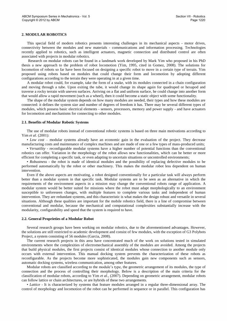
The ErekoBot robot in Figure 1(a), with four modules in series, has a considerable weight of 150 grams. Figure 1 (b)
shows the module encapsulation of aluminum embedded with a servomotor that has a torque capacity of 10-12 kg-cm
and 55 grams in weight. This creates problems related to mobility on higher frequency transmissions.
Figure 1. Modules ErekoBot β -5: (a) connected in series, bridge configuration; (b) detail of a single module.
ABCM Symposium Series in Mechatronics - Vol. 5 Copyright © 2012 by ABCM
Section VII - Robotics Page 1221
An external cable is responsible for a 12V/6V DC power supply to the modules, also to the control circuit, based on
microcontroller BasicStep BS1 and support circuitry. The programming and communication were centralized and
controlled by the software Basic Step, programmed in TBASIC with serial communication throughout the bus. The
prototype was able to run the algorithms with difficulties in the sidewinding walking type or second pitch-pitch
configuration (Gomez, 2008) with problems such as support, inertia and vibration during movement. Limitations with
locomotion, response time, precision and mechanical design made it impossible to continue this project and demanded
that it be improved into a more reliable system for working with the locomotion algorithms.
3. PROJECT EREKOBOT α
3.1. Design
The ErekoBot α was designed to apply new ideas and in order to overcome β-5 weight, connection and control
problems. Furthermore, new materials, joining methods and fabrication processes were also explored.
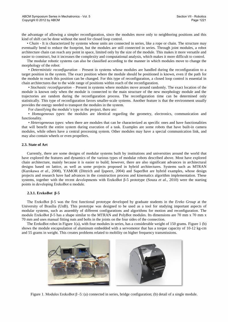
Figure (2) shows the module design and final implementation. The module volume is 40 mm x 40 mm x 40 mm, and
it is constructed in fiberglass.The change in size made it possible to reduce the module weight (ErekoBot α weighs 48
g) and still maintain the strength needed to support the requested efforts.
The modular faces of α project are overlaid by a Velcro fastener. In their paper, Dittrich and Ijspeert (2004),
classified the Velcro fastener as a very strong tissue and used it in YAMOR project. It can stand sheer forces up to 600
N if connected with enough pressure in the contact area. Each ErekoBot α modular face have male and female Velcro
fastener tissues in order to always allow connection between modules.
(a)
(b)
Figure 2. Module ErekoBot α: (a) previous design; (b) actual implementation.
As noted by Garcia (2008) and Dittrich (2004), MTRAN and YAMOR servomotors are selected by higher torque
necessities, with attention to the distance between the centers of rotation and gravity of adjacent modules. The current
servomotors used in ErekoBot α were chosen due to their suitable weight-torque relationship. They have 1.5 Kg-cm of
torque at 6 volts and metal gears, which allow greater durability and resistance to impact compared to the previously
servomotors used. This servo, with 15 grams, is the heaviest component but is justified by its torque to weight ratio,
higher than others analyzed, besides its low cost. Moreover, with the servo, one module is capable of raising two
coupled modules without relying neither on inertial forces nor on an increase in current discharge.
Table 1 gives a summary of the main features of ErekoBot α.
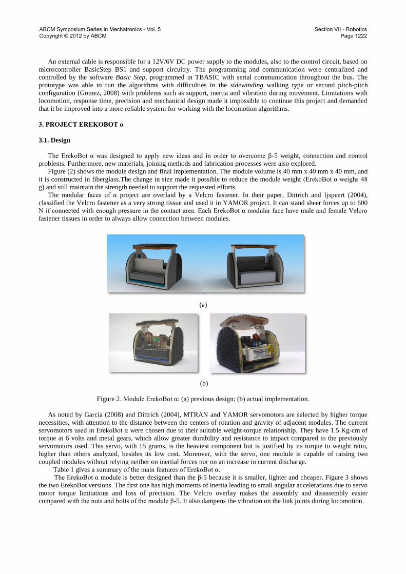
The ErekoBot α module is better designed than the β-5 because it is smaller, lighter and cheaper. Figure 3 shows
the two ErekoBot versions. The first one has high moments of inertia leading to small angular accelerations due to servo
motor torque limitations and loss of precision. The Velcro overlay makes the assembly and disassembly easier
compared with the nuts and bolts of the module β-5. It also dampens the vibration on the link joints during locomotion.
ABCM Symposium Series in Mechatronics - Vol. 5 Copyright © 2012 by ABCM
Section VII - Robotics Page 1222
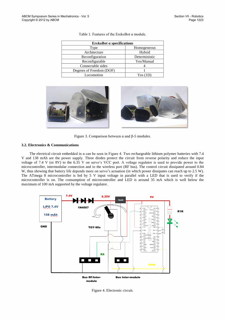
Table 1. Features of the ErekoBot α module.
ErekoBot α specifications
Type Homogeneous
Architecture Hybrid
Reconfiguration Deterministic
Reconfigurable Yes/Manual
Connectable sides 4
Degrees of Freedom (DOF) 1
Locomotion Yes (1D)
Figure 3. Comparison between α and β-5 modules.
3.2. Electronics & Communications
The electrical circuit embedded in α can be seen in Figure 4. Two rechargeable lithium polymer batteries with 7.4
V and 138 mAh are the power supply. Three diodes protect the circuit from reverse polarity and reduce the input
voltage of 7.4 V (or 8V) to the 6.35 V on servo’s VCC port. A voltage regulator is used to provide power to the
microcontroller, intermodular connection and to the wireless port (RF bus). The control circuit dissipated around 0.84
W, thus showing that battery life depends more on servo’s actuation (in which power dissipates can reach up to 2.5 W).
The ATmega 8 microcontroller is fed by 5 V input voltage in parallel with a LED that is used to verify if the
microcontroller is on. The consumption of microcontroller and LED is around 35 mA which is well below the
maximum of 100 mA supported by the voltage regulator.
Figure 4. Electronic circuit.
RX
R1K
Bus RF/Inter-
module
Bus Inter-module
1N4007
GND
5V 7.4V
6.35V
PWM
TGY-90s
ABCM Symposium Series in Mechatronics - Vol. 5 Copyright © 2012 by ABCM
Section VII - Robotics Page 1223
The microcontroller output is connected to servo’s signal input; where PWM signals (256 bytes) control the
servo’s position. For inter-module communication, there is a bus connecting two pins between the microcontroller and
its RX and GND pins. To communicate via radio (RF) with other wireless devices, a bus connected to the 5 V, GND
and RX pins of the microcontroller is used.
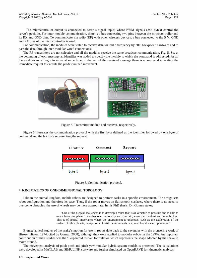
For communication, the modules were tested to receive data via radio frequency by “RF backpack” hardware and to
pass the data through inter-modular wired connections.
The RF transmitters are not selective and all the modules receive the same broadcast communication, Fig. 5. So, at
the beginning of each message an identifier was added to specify the module to which the command is addressed. As all
the modules must begin to move at same time, in the end of the received message there is a command indicating the
immediate request to execute the predetermined movement.
Figure 5. Transmitter module and receiver, respectively.
Figure 6 illustrates the communication protocol with the first byte defined as the identifier followed by one byte of
command and the last byte representing the request.
Figure 6. Communication protocol.
4. KINEMATICS OF ONE-DIMENSIONAL TOPOLOGY
Like in the animal kingdom, mobile robots are designed to perform tasks in a specific environment. The design sets
robot configuration and therefore its pace. Thus, if the robot moves on flat smooth surfaces, where there is no need to
overcome obstacles, the use of wheels may be more appropriate. In his PhD thesis, Dr. Gomez states:
“One of the biggest challenges is to develop a robot that is as versatile as possible and is able to
move from one place to another over various types of terrain, even the roughest and most broken.
This is of special importance where the environment is unknown, such as the exploration of the
surface of other planets, navigation in hostile environments or in search and rescue operations.”
Biomechanical studies of the snake’s motion for use in robots date back to the seventies with the pioneering work of
Hirose (Hirose, 1974, cited by Gomez, 2008), although they were applied to modular robots in the 1990s. An important
contribution of their studies was the "Serpentoid Curve" formulation which represents the shape adopted by the snake to
move around.
The movement analysis of pitch-pitch and pitch-yaw modular hybrid system models is presented. The calculations
were developed in MATLAB and SIMULINK software and further simulated on OpenRAVE for kinematic analyses.
4.1. Serpentoid Wave
ABCM Symposium Series in Mechatronics - Vol. 5 Copyright © 2012 by ABCM
Section VII - Robotics Page 1224

In a snake configuration, each module’s relative position is determined by the “Serpentoid Curve” (Gomez, 2008),
presented in Eq. (1):
, (1)
where A represents the angular amplitude of the movement, with units in degrees, T is the period, in seconds, t is the
time, in seconds, ∆Φ is the phase angle variation between modules, in degrees, Ψ1 is the first module phase angle and M
is the number of modules.
4.2. Differences between phases
The variation of the phase angle between modules is determined from the servo’s motor strength capability of lifting
adjacent modules. From Figure 7, obtained with MATLAB, it can be observed that the serpentoid wave pattern has less
support points for smaller phase angles, which requires higher torque from the reference module (first point).
ErekoBot α servo torque capability requires the phase angle to be greater than 60° for efficient locomotion. For
safety purposes, the phase angle decided upon was 90° in the paper’s analysis.
(a) (b)
(c) (d)
Figure 7. Configurations: (a) Amplitude (A) 60º, Phase (∆Φ) 30º; (b) A = 60°, ∆Φ = 45°;
(b) A = 60°, ∆Φ = 60°; A = 60°, ∆Φ = 90°,
4.3. Displacement
Acording to Gomez (2008), the snake’s displacement, x, is determined by Eq. (2), where is Amplitude and is
the distance between the two axes of rotation, as shown in Fig. 8.
(2)
During a period, the angular variation ∆Φ is four times the angular amplitude . Considering the angular velocity
known from servo specifications, the medium velocity should be defined as:
(3)
4.4. Analysis and Results
Servo motors are projected to normally operate in a range of 30º, 60º and 90º of angular amplitude, in which current
and specific speed-to-voltage ratios are determined. Considering manufacturer data and optimal motion with 8 modules,
an analysis of the system’s configuration using 60º and 60º / 90º are presented in Fig. 9, where each point represents the
module’s center of rotation.
ABCM Symposium Series in Mechatronics - Vol. 5 Copyright © 2012 by ABCM
Section VII - Robotics Page 1225
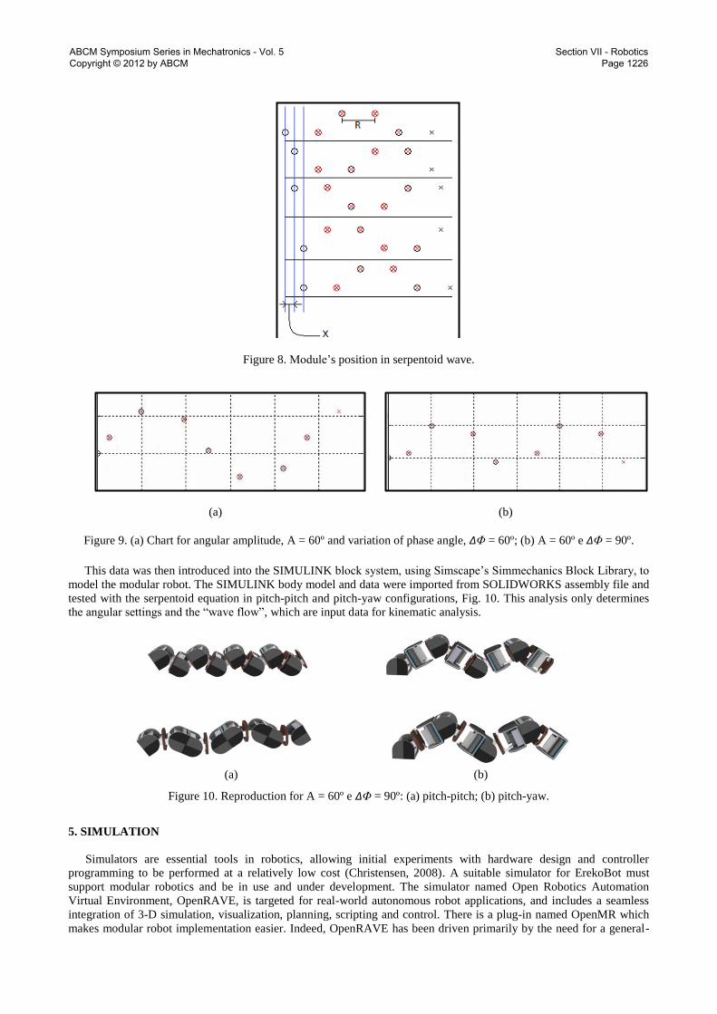
Figure 8. Module’s position in serpentoid wave.
(a) (b)
Figure 9. (a) Chart for angular amplitude, A = 60º and variation of phase angle, ∆Φ = 60º; (b) A = 60º e ∆Φ = 90º.
This data was then introduced into the SIMULINK block system, using Simscape’s Simmechanics Block Library, to
model the modular robot. The SIMULINK body model and data were imported from SOLIDWORKS assembly file and
tested with the serpentoid equation in pitch-pitch and pitch-yaw configurations, Fig. 10. This analysis only determines
the angular settings and the “wave flow”, which are input data for kinematic analysis.
(a) (b)
Figure 10. Reproduction for A = 60º e ∆Φ = 90º: (a) pitch-pitch; (b) pitch-yaw.
5. SIMULATION
Simulators are essential tools in robotics, allowing initial experiments with hardware design and controller
programming to be performed at a relatively low cost (Christensen, 2008). A suitable simulator for ErekoBot must
support modular robotics and be in use and under development. The simulator named Open Robotics Automation
Virtual Environment, OpenRAVE, is targeted for real-world autonomous robot applications, and includes a seamless
integration of 3-D simulation, visualization, planning, scripting and control. There is a plug-in named OpenMR which
makes modular robot implementation easier. Indeed, OpenRAVE has been driven primarily by the need for a general-
ABCM Symposium Series in Mechatronics - Vol. 5 Copyright © 2012 by ABCM
Section VII - Robotics Page 1226

purpose planning and scripting layer to be used in conjunction with low-level robotic packages such as ROS and Player
(Diankov, 2008).
The ErekoBot α was implemented in OpenRAVE. An ErekoBot α CAD design was converted into a numerical file in
which the modules were added one by one and simulated to achieve final configuration as shown in Fig. 11. Eight hinge
joints were set based on nominal servo specifications. The controller follows the kinematic study, so a different
equation drives each configuration. Locomotion follows what was expected with pitch-pitch moving straight forward in
a serpentoid movement and pitch-yaw lateral movements. Figure 11 shows pitch-pitch (a) and pitch-yaw (b) eight-
module-snake locomotion evolution.
Figure 11. Pitch-pitch (right side) and pitch-yaw(left side) serpentoid motion simulation in the OpenRAVE
environment.
5. TEST RESULTS
After simulation and construction of modules, it was possible to perform the first tests in order to make a validation
to confirm if all studies had a practical application for our purpose. For this, we used a standard procedure, with some
elements previously determined due to the geometry of the module and a characteristic formula. The results are shown
in Tab. 2,
Table 2. Test results.
Pitch-Pitch Configuration
1° Test 2° Test 3° Test
Amplitude 60° 30° 45°
Phase 90° 90° 90°
1° Round Distance: 30 cm Distance: 30 cm Distance: 30 cm
Time: 57.7 s Time: 46.1 s Time: 38.0 s
Average Speed: 0,520 cm/s Average Speed: 0,651 cm/s Average Speed: 0,781 cm/s
2° Round Distance: 28 cm Distance: 30 cm Distance: 30 cm
Time: 52.2 s Time: 45.1 s Time: 39.3 s
Average Speed: 0.536 cm/s Average Speed: 0.655 cm/s Average Speed: 0.764 cm/s
3° Round Distance: 31.5 cm Distance: 30 cm Distance: 30 cm
Time: 59.9 s Time: 44.4 s Time: 39.5 s
Average Speed: 0.526 cm/s Average Speed: 0.675 cm/s Average Speed: 0.759 cm/s
Overall Average Speed:
0.527 cm/s
Overall Average Speed:
0.660 cm/s
Overall Average Speed:
0.768 cm/s
Theoretical Overall Average
Speed: 1.389 cm/s
Theoretical Overall Average
Speed: 0.745 cm/s
Theoretical Overall Average
Speed: 1.085 cm/s
Loss of expected speed:
62.1%
Loss of expected speed:
11.4%
Loss of expected speed:
29.2%
ABCM Symposium Series in Mechatronics - Vol. 5 Copyright © 2012 by ABCM
Section VII - Robotics Page 1227

considering:
Distance between axes: R = 50 mm;
Angular Velocity: 60º/0.9 s or 1.164 rad/s. The speed is approximated as if calculated by using a
stopwatch)
The equation for average velocity, Eq. (3).
Comparing the three tests, it is observed that when the amplitude of the modules was high, they slipped a lot –first
test – and the expected speed was not reached, creating the idea that it is better to decrease the amplitude when it comes
to a smooth surface. When decreasing the amplitude – test 2 - the snake was almost able to reproduce the theoretical
speed. It is observed that the modules slipped only slightly on the surface, but a new problem arose, if there is a need for
a higher speed you should use a wider range. The test with the mean value between the previous two amplitudes – Test
3 – modules also slipped, but not as much as in the range of 60º. Its speed was greater than in the 30°, even slipping on
the surface.
In performing this test, we came to the conclusion that it is necessary to modify the part of the module that comes
into contact with the surface in order to increase friction. This can be done by adding a material for such ends, like
sandpaper, and / or making a chamfer or fillet these machines to increase the area of contact with the surface.
6. CONCLUSION
This paper presents a novel design for a modular prototype, ErekoBot α, and a side-by-side design comparison with
its predecessor, the ErekoBot β-5 module. The hardware system was described and a kinematic analysis was discussed.
The system’s feasibility was demonstrated through simulation.
There are several important issues remaining in the ErekoBot project under development. Implementing a self-
reconfigurability is a major step in a hybrid modular robot scale, and research is required for inserting a controllable
connection mechanism in a future version. Sensors, feedback ports and processing power are also issues for enabling
the module to perform more complex motions and reconfiguration algorithms. Also, a distributed control algorithm for
autonomous actuation is an objective for future work, in order to explore the capability of self-repair in the field, which
is an important quality present in modern modular robot architecture.
7. REFERENCES
Christensen, D., Brandt, D., Stoy, K., Schultz, U. P., 2008 “A Unified Simulator for Self-Reconfigurable Robots”,
Proceedings of the International Conference on Intelligent Robots and Systems, IEEE/RSJ, Acropolis Convention
Center, Nice, France, pp. 870-876.
Diankov, R., Kuffner, J., 2008 “OpenRAVE: A Planning Architecture for Autonomous Robotics”, Robotics Institute,
Carnegie Mellon University, Pittsburgh, Pennsylvania, 15 p.
Dittrich, E., Ijspeert, A., 2004, “Modular Robot Unit – Characterisation, Design and Realisation”, 03 Mar. 2010,
<http://birg.epfl.ch/page53469.html> .
Garcia, R., Stoy, K., 2008, “The Odin Modular Robot: Eletronics and Communication”, The Maersk Mc-Kinney Moller
Institute, University of Southern Denmark, Odense, Denmark, 20 Mar. 2010,
<http://www.mip.sdu.dk/~rimen05/Files/GarciaMasterScienceThesis.pdf>.
Gómez, J., 2008, “Modular Robotics and Locomotion: Application to Limbless Robots. European PhD Thesis.
Universidad Autonoma de Madrid, 451 p.
Guimarães, P. V. B., Souza, N. C. A.,Viana, D. M., Koike, C. M. C. C., 2010, “Estudo Cinemático do protótipo de um
robô modular”, II Encontro de Ciência e Tecnologia Gama, Brasília, Brazil, 4 p.
Hirose, S., 1993. “Biologically Inspired Robots - Snake-like Locomotor and Manipulator”, Science Press, Oxford
University, 240 p.
Kamimura, A., Yoshida, E., Murata, S., Kurokawa, H., Tomita, K. and Kokaji, S., 2007, “Self-reconfigurable modular
robot M-TRAN: distributed control and communication”, Proceedings of the 1st International Conference on Robot
Communication and Coordination, Article No: 21, ACM International Conference Proceeding Series, Vol. 318.
Kurokawa, H., Tomita, Y., Kamimura, A., Kokaji, S., Hasuo, T. and Murata, S., 2008, “Distributed Self-
Reconfiguration of M-TRAN III Modular Robotic System”, The International Journal of Robotics Research, 27-3-4:
pp 373-386.
Souza, N. C. A., Dutra R. C., Brito, L., S., Viana, D. M., Koike, C. M. C. C, 2010,“Projeto e Construção de um Robô
Modular”, VI Congresso Nacional de Engenharia Mecânica, Campina Grande, Brazil, 10 p.
Yim, M. H., Homans, S. B., Roufas, K. D., 2001, “Climbing with snake-like robots”, IFAC Workshop on Mobile Robot
Technology, May 21-22, Jejudo, Korea.
Yim, M., Shen, W., Salemi, B., Rus, D., Moll, M., Lipson, H., Klavins, E. and Chirikjian, G., 2007, “Modular
Reconfigurable Robot Systems”, IEEE Robotics & Automation Magazine.
ABCM Symposium Series in Mechatronics - Vol. 5 Copyright © 2012 by ABCM
Section VII - Robotics Page 1228