erection work, operating and maintenance...
TRANSCRIPT

AASPV series
Erection Work, Operating and Maintenance Instructions ANDRITZ vertical split double suction pump
ASPV series for ASP350-680R
ASPV series Erection Work, Operating and Maintenance Instructions
Rev.0, Printed: 2011.07 TITLE PAGE #455857V1-DECHBLATT
The operating manual is protected by copyright. All usual rights reserved. It must not be w holly or partly reproduced without authorization by ANDRITZ. Contraventions shall entail damage claims and may have penal consequences. All rights shall also be reserved for any patents granted, registration of trade marks and technical modif ications w ithout prior notif ication.
2013 Andritz

ASPV series Erection Work, Operating and Maintenance Instructions
Rev.0, Printed: 2011.07 TABLE OF CONTENTS Page1 of 2
Table of contents 1 INTRODUCTION ······················································································ 1
1.1 Use ······························································································ 1 1.2 Standards and guidelines ··································································· 1 1.3 How to use the manual ······································································ 2 1.4 Warranty and guarantee····································································· 3 1.5 Manufacturer’s name and address ························································ 4 1.6 Copyright ······················································································ 4
2 SAFETY ································································································· 1 2.1 General safety regulations·································································· 1 2.2 Danger and warning signs ·································································· 1 2.3 Designated use ··············································································· 2 2.4 General remarks on machine/plant safety ··············································· 2 2.5 User’s obligations ············································································ 3 2.6 General obligations of personnel·························································· 5 2.7 Safety devices ················································································ 6 2.8 Personal protective apparel ································································ 7 2.9 Safety at the machine installation site ···················································· 7 2.10 Temperature ··················································································· 7 2.11 Noise ··························································································· 7 2.12 Electrical equipment ········································································· 8 2.13 Steam and fumes/smoke ···································································· 8 2.14 Greases ························································································ 8
3 TECHNICAL DATA ··················································································· 1 3.1 Dimensioned drawing ······································································· 1 3.2 Assembly drawing ··········································································· 3 3.3 Main components of ASPV 350-680R ····················································· 4
3.3.1 Main components of ASPV350-680 ············································································ 4 4.1 Field of application··········································································· 5 4.2 Type specification ···········································································10
4.3.1 Applicable standards ····························································································· 10 4.3.2 Model designation ································································································· 10
4.3 Application limiting values ································································ 11 Technological Description············································································14 5.1 General ························································································15 5.2 Safety regulations ···········································································15 5.3 Haulage ·······················································································16 5.4 Storage ························································································19 5.5 Installation ····················································································20
5.5.1 Erection of the ASPV pump ···················································································· 21 5.5.2 Pipework ·············································································································· 23
5.6 Instruments···················································································25 5.7 Cold test ······················································································26

ASPV series Erection Work, Operating and Maintenance Instructions
Rev.0, Printed: 2011.07 TABLE OF CONTENTS Page2 of 2
4 START-UP ······························································································ 1 6.1 General ························································································· 1 6.2 Safety regulations ············································································ 1 6.3 Prerequisites for start-up ··································································· 2 6.4 Start-up························································································· 4 6.5 Certificates ···················································································· 5
5 OPERATION···························································································· 1 7.1 General ························································································· 1 7.2 Safety regulations ············································································ 1 7.3 Control via DCS··············································································· 2 7.4 Starting ························································································· 2 7.5 Checks after initial start-up ································································· 3 7.6 Normal operation ············································································· 4 7.7 ASPV pump requirements (delivery head and flow rate) ······························ 5 7.8 Stopping ······················································································· 6 7.9 Operating malfunctions and troubleshooting ··········································· 7
6 MAINTENANCE ······················································································· 1 8.1 General ························································································· 1 8.2 Safety regulations ············································································ 1 8.3 Regular maintenance ········································································ 2 8.4 Maintenance schedule······································································· 4 8.5 Fasteners ······················································································ 5 8.6 Grease Lubrication··········································································· 6 8.7 Aliging the coupling ········································································· 8 8.8 Removing and installing the rotor unit ··················································· 9 8.9 Changing the bearing assembly ··························································15 8.10 Changing the mechanical seal ····························································18 8.11 Removing and installing the impeller ····················································19 8.12 Turning and balancing the impeller ······················································25
ASPV series Erection Work, Operating and Maintenance Instructions
Rev.0, Printed: 2011.07 INTRODUCTION Chapter 1, Page1 of 4
1 INTRODUCTION This manual is part of the technical documentation of Andritz. It is intended as a supplement to the training provided, to supply the basic knowledge required for proper, safe and economical use of the plant and machinery delivered by Andritz. Observing these instructions helps avoid hazards and reduce repair and downtime costs, as well as increasing the reliability and useful life of machines.
1.1 Use
Target group This operating manual is intended for users with a knowledge of mechanical engineering and is for the exclusive use of the operator of the mill and his personnel.
Personnel entrusted with work on the machine must have read and understood these operating instructions and comply with them. This refers in particular to the follow ing tasks:
Handling, starting and stopping
Troubleshooting
Maintenance and upkeep
Haulage Maintenance and disposal of process materials, cleaning of machine
and area around the machine.
The follow ing sections are especially important:
The Chapter on SAFETY,
The safety instructions contained in various other chapters
Supplementary instructions
The mill operator shall complete this manual by adding national regulations on safety at work, health protection and environmental protection.
Instructions on any special operational conditions concerning work organization, sequence of work/operations and the personnel assigned to the job shall also be added. This also includes instructions on supervising and reporting obligations.
Safekeeping Keep the entire operating manual near the place w here the machine is installed and w ithin easy reach
1.2 Standards and guidelines The machine/plant has been built in accordance with state-of-the-art standards and the recognized safety rules. The equipment conforms with the equivalent appropriate standards

ASPV series Erection Work, Operating and Maintenance Instructions
Rev.0, Printed: 2011.07 INTRODUCTION Chapter 1, Page2 of 4
1.3 How to use the manual
Presentation Chapter and paragragh headings are printed in capitals in the continuous test
SAFETY
Designations of indicating and handling elements are written in inverted commas in the continuous text.
Operate sw itch “xxx”
Lists w ithout numbering do not require operations to be carried out in a certain order.
Pictograms The follow ing pictograms are used in the manual:
Warning signs.
Warning signs are shown with an explanation of the type of the hazard.
The meaning of the different graduations of hazards are described in the Chapter on SAFETY.
Marks an instruction on handling of the machine of system.
Marks a useful piece of information
Marks a cross-reference to another Chapter with absolute path indication.
e.g. /ASPV PUMP/SAFETY
Work steps (operations)
Work steps are presented in tables. Work steps are numbered and must be carried out in the order specif ied.
Item numbers 411.2 The item numbers shown in this format refer to the assembly draw ing and the parts list.
Numbering of pages, tables and figures
Pages
Tables
Figures
consecutive numbering of Chapters 2-1
Tab. + Continuous numbering of Chapters Tab.2-1
Fig. + Consecutive numbering of Chapters Fig.2-1
Abbreviations Tab.
Fig.
Table
Figure
ASPV series Erection Work, Operating and Maintenance Instructions
Rev.0, Printed: 2011.07 INTRODUCTION Chapter 1, Page3 of 4
1.4 Warranty and guarantee ANDRITZ’s general terms of delivery and sale shall apply.
Guarantee and liability claims on ANDRITZ shall become void if personal injury or material damage is caused by one or several of the following:
Use of the machine/system for any purpose other than its designated use.
Non-conformity of erection work, start-up and handling of the machine/system.
Non-observance of the safety instructions in the manual.
Non-authorized structural changes to the machine/system.
Non-observance of the maintenance and upkeep instructions.
In the event of a claim for repair under guarantee, ANDRITZ reserves the right to assess the damage to the machine/system.
ASPV series Erection Work, Operating and Maintenance Instructions
Rev.0, Printed: 2011.07 INTRODUCTION Chapter 1, Page4 of 4
1.5 Manufacturer’s name and address
ANDRITZ (CHINA) LTD
No.83, Zone B, Sanshui Central Technical & Industrial park, Lexin Road, Leping, Sanshui District, Foshan.
Our service department will be pleased to help you and can be contacted at:
ANDRITZ (CHINA) LTD
No.83, Zone B, Sanshui Central Technical & Industrial park, Lexin Road, Leping, Sanshui District, Foshan.
Service department for pumps
Tel.: 0757-66633102
Fax: 0757-66633148
Email: [email protected]
1.6 Copyright The operating manual is protected by copyright. All usual rights reserved.It must not be w holly or partly reproduced without authorization by Andritz consequences. All rights shall also be reserved for any patents granted, registration of trade marks and technical modif ications without prior notif ication.
2013 Andritz
ASPV series Erection Work, Operating and Maintenance Instructions
Rev.0, Printed: 2011.07 SAFETY Chapter 2, Page 1 of 8
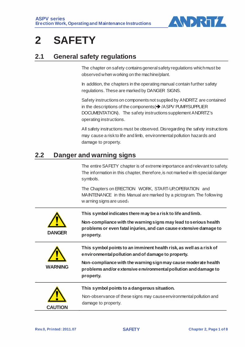
2 SAFETY 2.1 General safety regulations
The chapter on safety contains general safety regulations which must be observed when working on the machine/plant.
In addition, the chapters in the operating manual contain further safety regulations. These are marked by DANGER SIGNS.
Safety instructions on components not supplied by ANDRITZ are contained in the descriptions of the components( /ASPV PUMP/SUPPLIER DOCUMENTATION). The safety instructions supplement ANDRITZ’s operating instructions.
All safety instructions must be observed. Disregarding the safety instructions may cause a risk to life and limb, environmental pollution hazards and damage to property.
2.2 Danger and warning signs The entire SAFETY chapter is of extreme importance and relevant to safety. The information in this chapter, therefore, is not marked w ith special danger symbols.
The Chapters on ERECTION WORK, START-UP,OPERATION and MAINTENANCE in this Manual are marked by a pictogram. The following w arning signs are used:
DANGER
This symbol indicates there may be a risk to life and limb.
Non-compliance with the warning signs may lead to serious health problems or even fatal injuries, and can cause extensive damage to property.
WARNING
This symbol points to an imminent health risk, as well as a risk of environmental pollution and of damage to property.
Non-compliance with the warning sign may cause moderate health problems and/or extensive environmental pollution and damage to property.
CAUTION
This symbol points to a dangerous situation.
Non-observance of these signs may cause environmental pollution and damage to property.

ASPV series Erection Work, Operating and Maintenance Instructions
Rev.0, Printed: 2011.07 SAFETY Chapter 2, Page 2 of 8
Further symbols and pictograms used are described under INTRODUCTION.
2.3 Designated use The ASPV pump should only be used according to the specif ications forming part of the purchase order.
Any change in the application must be checked by the operator and, if necessary, approved by Andritz.
Non-observance of the application can lead to environmental or property damage, or to personal injury.
Any modif ications to the scope of supply made w ithout the agreement of andritz are considered contrary to the designated use.
The term designated use shall also include adherence to the operating instructions, observance of the operating, inspection and maintenance conditions and of the regulations on cleaning and upkeep.
2.4 General remarks on machine/plant safety The ASPV pump has been built in accordance with state-of-the-art standards and the recognized safety rules. Nevertheless, its use may constitute a risk to life and limb of the user of third parties, of cause damage to the machine/plant and to other material property.
The ASPV pump may only be operated w hen in perfect condition and w ith due consideration to safety and the risks involved. All protective devices and the emergency cut-out devices must be in place and fully functional.
Malfunctions and unforeseen changes in the ASPV pump must be remedied immediately.
ASPV series Erection Work, Operating and Maintenance Instructions
Rev.0, Printed: 2011.07 SAFETY Chapter 2, Page 3 of 8
2.5 User’s obligations
Designated use The user of the ASPV pump is responsible for its designated use.
Work instructions In addition to the operating instructions, applicable legal stipulations and other rules governing the safety at work, health and environmental protection must be observed and personnel instructed in them.
Qualification of assigned personnel
The ASPV pump may only be operated, maintained and serviced by authorized, skilled personnel w ith hands-on training.
Personnel must not be below the legal minimum age.
Any person urndergoing training, serving an apprenticeship or being instructed must not w ork on the ASPV pump except under the supervision of an experienced person.
Instructions The user’s operating and maintenance personnel will be instructed by manufacturer personnel or his contractual distributor upon completion of installation w ork.
The user undertakes to have new, additional operating and maintenance personnel instructed in machine and maintenance of the ASPV pump to the same extent and applying the same care, and w ith due consideration to the safety instructions.
Workers entrusted with the transportation, erection work and start-up of the ASPV pump must have read and understood the operating instructions,especially the chapter on SAFETY, the safety instructions concerning a certain activity, as well as the safety instructions issued by sub-suppliers.
Definition of areas of responsibility
The user shall be responsible for:
definition of the machine operator’s responsibility and his right to give instructions
Definition of the contents and responsibility for keeping the records on functioning and any failure of the monitoring equipment (log book)
Personnel areas of responsibility in terms of operating, Tooling, maintenance and upkeep.
ASPV series Erection Work, Operating and Maintenance Instructions
Rev.0, Printed: 2011.07 SAFETY Chapter 2, Page 4 of 8
Inspections The operator undertakes
To check at regular interval w hether the safety instructions and regulations governing work on the ASPV pump are observed.
To carry out regular training to confirm the level of know ledge of the operating and maintenance personnel.
Attaching safety devices
The user shall ensure that the follow ing equipment, regulations, symbols and instructions are mounted in the production area;
Safety devices and regulations (see Chapter 2.7)
Fire prevention regulations
Markings on the f loor for driveways, protective fencing and danger areas (yellow)
Fencings and covers
Railings (foot, center and chest height) Emergency lighting
Emergency-off switch
Repair sw itch for drive motors Signs on f ire-f ighting equipment
Signs for emergency calls
Direction arrow s to exits Direction arrow s to escape routes
Signs to f irst-aid post

ASPV series Erection Work, Operating and Maintenance Instructions
Rev.0, Printed: 2011.07 SAFETY Chapter 2, Page 5 of 8
2.6 General obligations of personnel To avoid personal and material damage anybody working on the machine shall
Observe the safety instructions in the operating regulations and on the ASPV pump.
Stop and secure the ASPV pump in case of a safety-relevant functional disorder. Report the disorder and have it repaired immediately.
Not perform any w ork in a manner disregarding safety considerations.
Use only the machine accesses, paths and passages foreseen for this purpose.
Not touch rotating parts and/or reach out beyond them.
Keep the machine and the w ork place clean, not place tools or other objects on the ASPV pump.
Not w ear long hair hanging dow n.
Familiarize themselves before starting work with the function and any failure of machine monitoring equipment (log book).
Refrain from smoking in the vicinity of the ASPV pump.
Personal protective apparel must be w orn when working on the ASPV pump. (see Section 2.8)
Due to the high temperatures and humidity, people w earing glasses may f ind that their glasses steam up, thus exposing the w earer to a risk of injury.
The operating personnel must be acquainted w ith the safety data sheets in order to be able to recognize how dangerous the chemicals can be.

ASPV series Erection Work, Operating and Maintenance Instructions
Rev.0, Printed: 2011.07 SAFETY Chapter 2, Page 6 of 8
2.7 Safety devices The ASPV pump must not be operated w ithout effective safety equipment.
Safety equipment must not be circumvented, dismantled or made unserviceable. The safety equipment is here to protect operating personnel.
Safety equipment and access thereto must be kept free.
Safety covers the ASPV pump must not be operated w ithout safety covers mounted.
Fig. 2-1 shows the protective covers for the ASPV pump.
Fig. 2-1 Protective covers for the ASPV pump
ASPV series Erection Work, Operating and Maintenance Instructions
Rev.0, Printed: 2011.07 SAFETY Chapter 2, Page 7 of 8
2.8 Personal protective apparel
General Safety equipment
The follow ing must always be worn when performing work on the ASPV pump:
Protective clothing to prevent the pulp from coming into contact with the skin.
Gloves to prevent hand injuries
Goggles to prevent eye injuries
Safety shoes as protection against crushing The required personal ear protection to avoid hearing defects
Standard hard hat as protection against head injuries
2.9 Safety at the machine installation site Adequate lighting must be provided (industrial lighting).
The foundations must be sized to w ithstand the loads caused by the ASPV pump. Customer w ill be provided with a load plan.
Area around machine and marked escapes to be kept free. Area around machine must be marked an danger zone.
Make sure machine and surrounding area are kept clean. In particular, Oil and grease on the f loor and on machine elements may cause slipping. This is therefore a considerable source of injuries, as are tools.
The f loor around the ASPV pump must be provided w ith a non-slip f inish.
Ramps, platforms and lif ts must be used to avoid injury or excessive physical effort.
2.10 Temperature The ASPV pump is designed for a stock temperature of 55˚C. If pulp at temperatures higher than 65˚C is to be used, the operator must take the necessary safety measures (e.g. protective gloves, training of operating staff, etc.).
2.11 Noise The total noise emissions from all machines in the production room can restrict spoken communication and impair hearing.
The machine is designed such that no operator is required in the immediate vicinity of the machine. Appropriate hearing protection should be w orn throughout maintenance and adjusting w ork while the machine is running.
ASPV series Erection Work, Operating and Maintenance Instructions
Rev.0, Printed: 2011.07 SAFETY Chapter 2, Page 8 of 8
2.12 Electrical equipment All w ork on the electrical equipment, w ithout exception, must be carried out by skilled electricians.
Any form of contact with electrical equipment may cause fatal injuries.
Employees performing w ork on live parts should be accompanied by an assistant who can operate the emergency switch if necessary.
Users of medical electronic equipment, such as pacemakers, must not enter the electric danger zone.
Machine must be earthed to avoid electrostatic loading.
2.13 Steam and fumes/smoke Unusual chemical reactions may take place in the f ibre stock during a prolonged standstill and hazardous fumes may be produced.
The machine must be thoroughly cleaned if shut down for longer than 2 hours.
The area must be suff iciently ventilated.
2.14 Greases The safety instructions for the products concerned must be observed when handling grease and other chemical substances.
Suitable skin protection is required w hen handling aggressive media. See manufacturers’ information for the type of skin protection required.
Also observe relevant requirements for disposal

ASPV series Erection Work, Operating and Maintenance Instructions
Rev.0,Printed: 2013.03 ERECTION WORK and TRANSPORT Chapter 5, Page 1 of 11
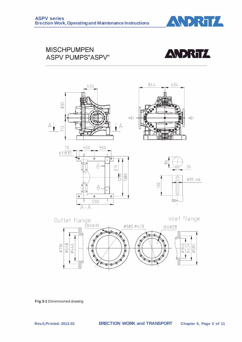
3 TECHNICAL DATA 3.1 Dimensioned drawing
3.1-1 Dimension drawing
ASPV series Erection Work, Operating and Maintenance Instructions
Rev.0,Printed: 2013.03 ERECTION WORK and TRANSPORT Chapter 5, Page 2 of 11
Fig 3-1 Dimensioned drawing
ASPV series Erection Work, Operating and Maintenance Instructions
Rev.0,Printed: 2013.03 ERECTION WORK and TRANSPORT Chapter 5, Page 3 of 11
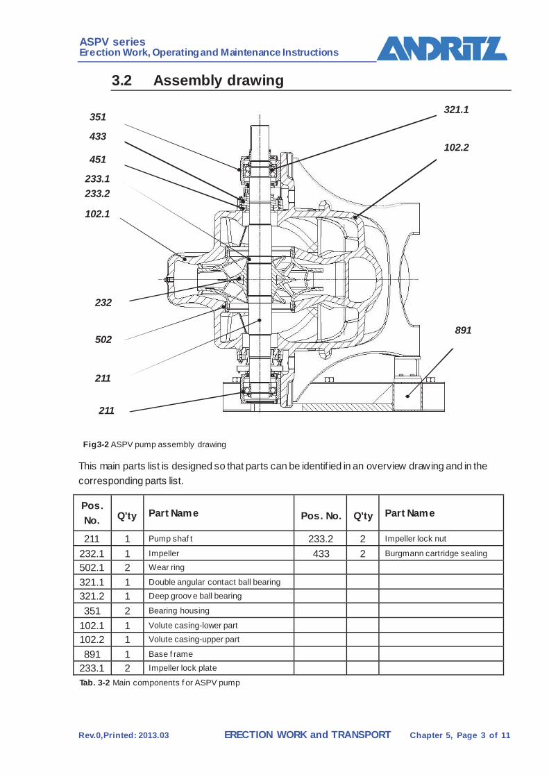
3.2 Assembly drawing
Fig3-2 ASPV pump assembly drawing
This main parts list is designed so that parts can be identif ied in an overview drawing and in the corresponding parts list.
Pos. No. Q’ty Part Name Pos. No. Q’ty Part Name
211 1 Pump shaf t 233.2 2 Impeller lock nut
232.1 1 Impeller 433 2 Burgmann cartridge sealing
502.1 2 Wear ring
321.1 1 Double angular contact ball bearing
321.2 1 Deep groov e ball bearing
351 2 Bearing housing
102.1 1 Volute casing-lower part
102.2 1 Volute casing-upper part
891 1 Base f rame
233.1 2 Impeller lock plate
Tab. 3-2 Main components f or ASPV pump
102.2
102.1
232
211
502 891
321.1
433
233.1 233.2
351
211
451
ASPV series Erection Work, Operating and Maintenance Instructions
Rev.0,Printed: 2013.03 ERECTION WORK and TRANSPORT Chapter 5, Page 4 of 11
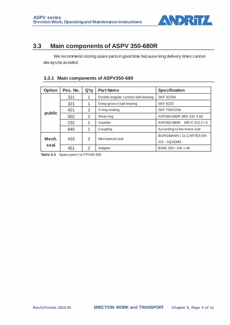
3.3 Main components of ASPV 350-680R We recommend storing spare parts in good time because long delivery times cannot
alw ays be avoided.
3.3.1 Main components of ASPV350-680
Option Pos. No. Q’ty Part Name Specification
public
321 1 Double angular contact ball bearing SKF 3220A
321 1 Deep groov e ball bearing SKF 6220
421 2 V-ring sealing SKF TSN220A
502 2 Wear ring ASP350-680R 385/ 332 X 60
232 1 Impeller ASP350-680R 680 X 310 Z= 5
840 1 Coupling According to the motor size
Mech. seal
433 2 Mechanical seal BURGMANN | 11-CARTEX-SN -
115 - AQ1EMG
451 2 Adapter BS95 250 / 150 x 40
Table 3-3 Spare parts f or FPV40-400
ASPV series Erection Work, Operating and Maintenance Instructions
Rev.0,Printed: 2013.03 ERECTION WORK and TRANSPORT Chapter 5, Page 5 of 11
DESCRIPTION
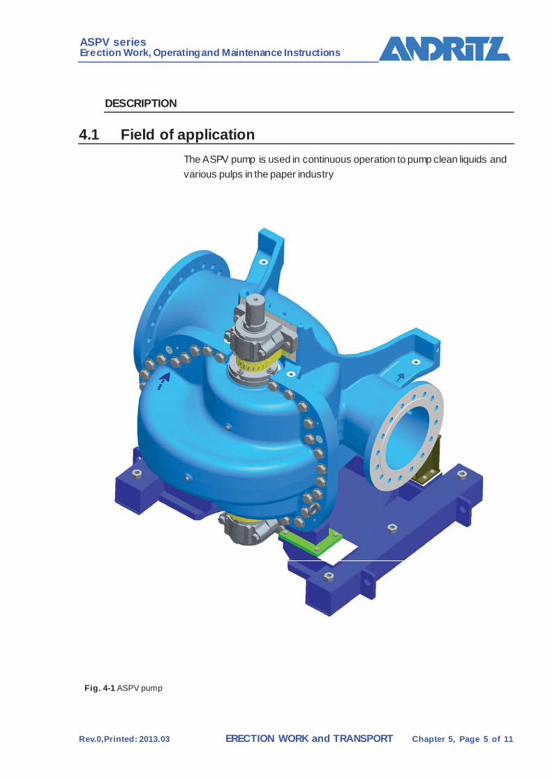
4.1 Field of application The ASPV pump is used in continuous operation to pump clean liquids and various pulps in the paper industry
Fig. 4-1 ASPV pump

ASPV series Erection Work, Operating and Maintenance Instructions
Rev.0,Printed: 2013.03 ERECTION WORK and TRANSPORT Chapter 5, Page 6 of 11
Volute casing- upper part (102.2) and lower part (102.1)
Function: Guiding the medium w ith a favourable f low pattern. Converting the speed energy into pressure energy.
Design:
Pressure-sealed, double-flow pump casing with delivery and suction channels
Suction and delivery f lange
Mounting for the bearing housing w ith bearing assembly, shaft and impeller.
Fig. 4-2 v olute casing
Pump shaft (211) Function: Holding the impeller, shaft seal, bearing and coupling. Transmitting the drive energy to the impeller and thus, to the medium.
Design: Drive shaft made of high-quality, acid-proof stainless steel
Fig. 4-3 Pump shaf t
Suction side
Delivery side 102.2
102.1
Shaft (211) bearing
Mechanical seal Impeller(232,233) bearing

ASPV series Erection Work, Operating and Maintenance Instructions
Rev.0,Printed: 2013.03 ERECTION WORK and TRANSPORT Chapter 5, Page 7 of 11
Impeller (232,233) Function: Accelerating the medium by charging it w ith energy.
Design: Bipartite, made of acid-proof stainless cast steel.
Wear ring (502) Function:Chokebetw een suction and delivery side of the impeller.
Design: Hydraulically optimized ring made of acidproof stainless steel.
Fig. 4-4 Wear ring
Shaft seal Function: Seal betw een medium (suction side) and the atmosphere
Design: Stuff ing bow with stuffing box gland, sealing water ring, adjustable stuff ing box gland, and sealing water connection.
Fig. 4-5 Stuffing box
Item Component Item Component
211 Pump shaft 461 Stuffing box packing
451 Seal casing 458 Seal water ring
452 Stuffing box gland 902.3 Stud bolt
524.1 Shaft protection sleeve
Tab. 4-1 Stuf fing box parts
502 502
458
211
461
451
524.1
452
902.3
Medium Atmosphere
ASPV series Erection Work, Operating and Maintenance Instructions
Rev.0,Printed: 2013.03 ERECTION WORK and TRANSPORT Chapter 5, Page 8 of 11
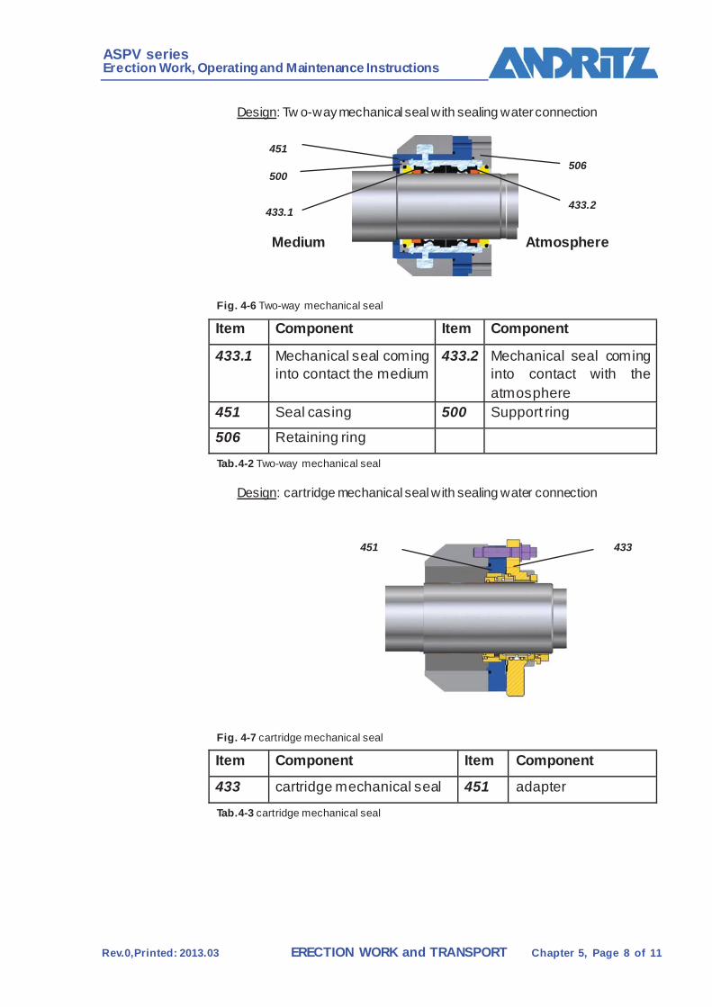
Design: Tw o-way mechanical seal with sealing water connection
Fig. 4-6 Two-way mechanical seal
Item Component Item Component
433.1 Mechanical seal coming into contact the medium
433.2 Mechanical seal coming into contact with the atmosphere
451 Seal casing 500 Support ring
506 Retaining ring
Tab.4-2 Two-way mechanical seal
Design: cartridge mechanical seal with sealing water connection
Fig. 4-7 cartridge mechanical seal
Item Component Item Component
433 cartridge mechanical seal 451 adapter
Tab.4-3 cartridge mechanical seal
451
500
433.1
506
433.2
Atmosphere Medium
433 451
ASPV series Erection Work, Operating and Maintenance Instructions
Rev.0,Printed: 2013.03 ERECTION WORK and TRANSPORT Chapter 5, Page 9 of 11
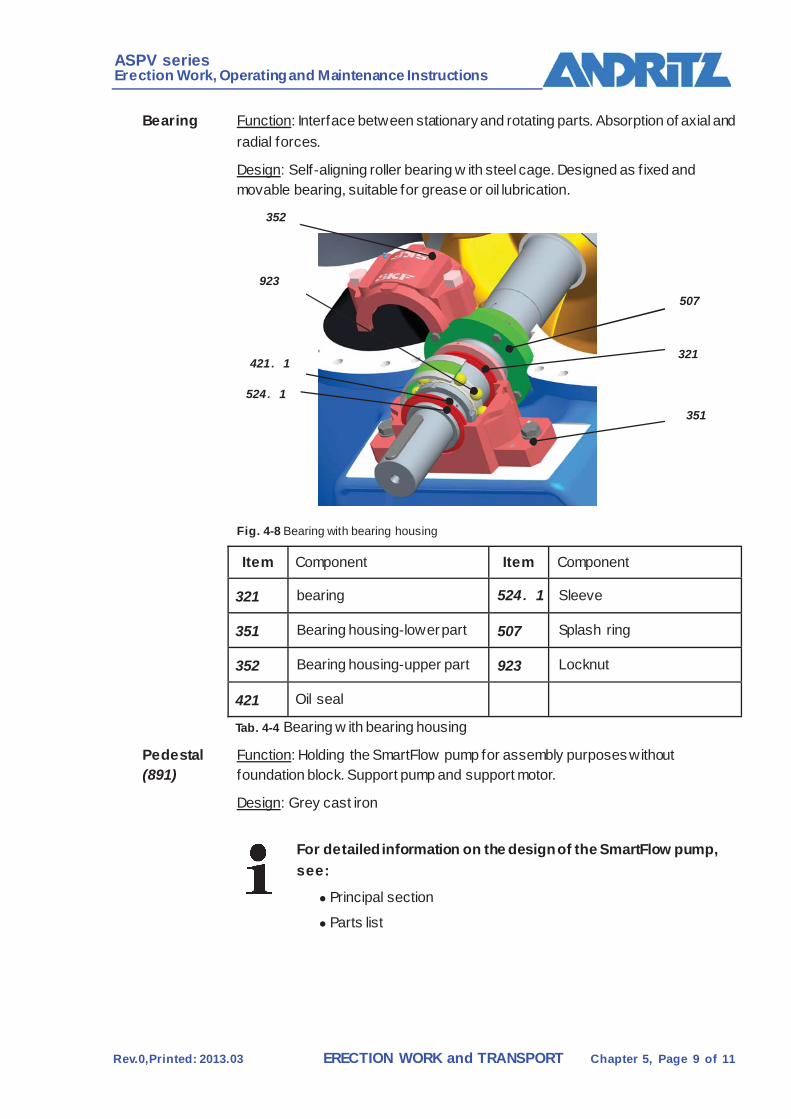
Bearing Function: Interface between stationary and rotating parts. Absorption of axial and radial forces.
Design: Self-aligning roller bearing w ith steel cage. Designed as f ixed and movable bearing, suitable for grease or oil lubrication.
Fig. 4-8 Bearing with bearing housing
Item Component Item Component
321 bearing 524..1 Sleeve
351 Bearing housing-lower part 507 Splash ring
352 Bearing housing-upper part 923 Locknut
421 Oil seal
Tab. 4-4 Bearing w ith bearing housing
Pedestal (891)
Function: Holding the SmartFlow pump for assembly purposes without foundation block. Support pump and support motor.
Design: Grey cast iron
For detailed information on the design of the SmartFlow pump, see:
Principal section
Parts list
507
321
351
421.1
524.1
923
352
ASPV series Erection Work, Operating and Maintenance Instructions
Rev.0,Printed: 2013.03 ERECTION WORK and TRANSPORT Chapter 5, Page 10 of 11
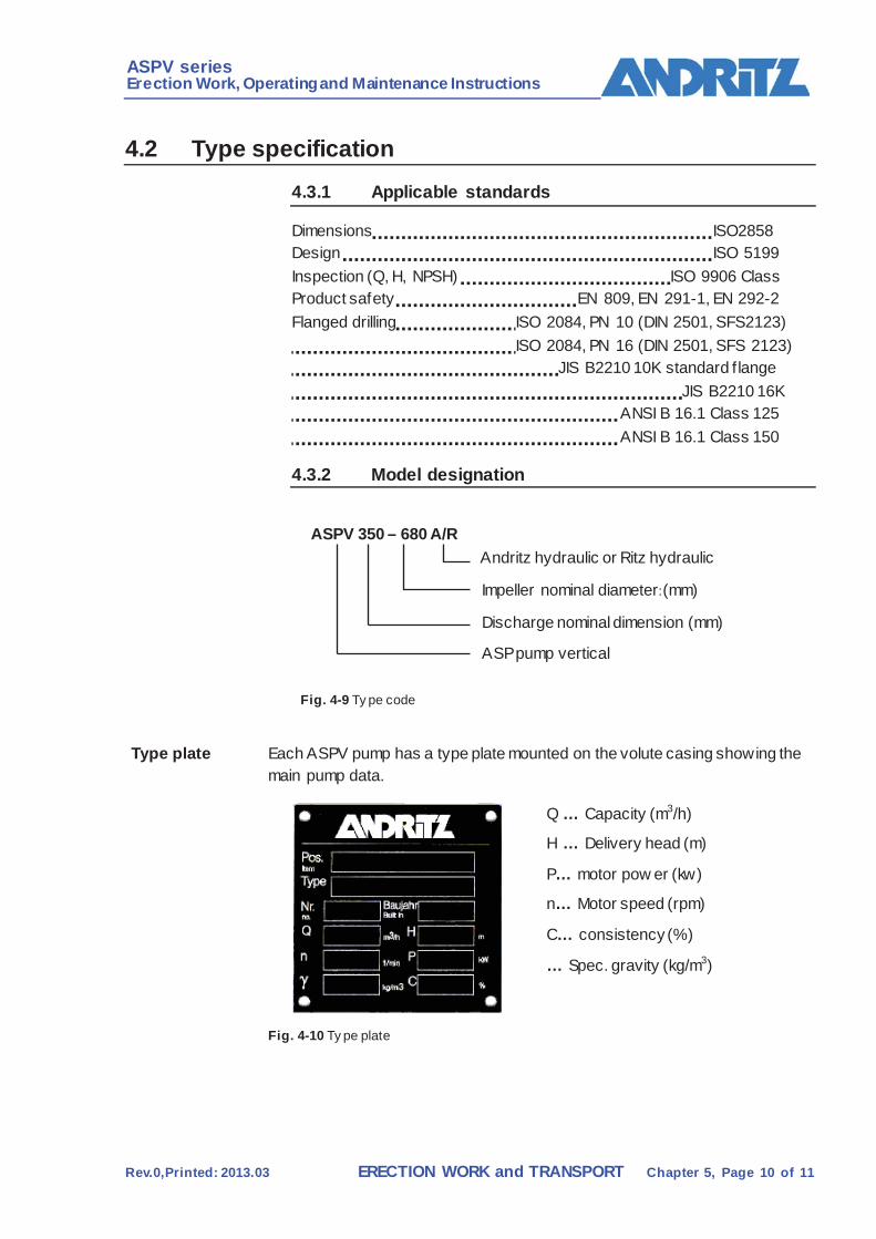
4.2 Type specification
4.3.1 Applicable standards
Dimensions ISO2858 Design ISO 5199 Inspection (Q, H, NPSH) ISO 9906 Class Product safety EN 809, EN 291-1, EN 292-2 Flanged drilling ISO 2084, PN 10 (DIN 2501, SFS2123) ISO 2084, PN 16 (DIN 2501, SFS 2123) JIS B2210 10K standard f lange JIS B2210 16K ANSI B 16.1 Class 125 ANSI B 16.1 Class 150
4.3.2 Model designation
ASPV 350 – 680 A/R Andritz hydraulic or Ritz hydraulic
Impeller nominal diameter:(mm)
Discharge nominal dimension (mm)
ASP pump vertical
Fig. 4-9 Ty pe code
Type plate Each ASPV pump has a type plate mounted on the volute casing showing the main pump data.
Q … Capacity (m3/h)
H … Delivery head (m)
P… motor pow er (kw)
n… Motor speed (rpm)
C… consistency (%)
… Spec. gravity (kg/m3)
Fig. 4-10 Ty pe plate

ASPV series Erection Work, Operating and Maintenance Instructions
Rev.0,Printed: 2013.03 ERECTION WORK and TRANSPORT Chapter 5, Page 11 of 11
4.3 Application limiting values The limit values shown for the ASPV pump in the present Chapter should not be exceeded under any circumstances.
Pressure and temperature limits
The permitted pressure and temperature limit values according to table (tab. 4-5) must be observed.
Type Pressure in suction branch
Pressure in delivery branch
Temperature Medium
ASPV350-680R 0.2 min / 26 bar max 26 bar max. 50˚C max. Tab. 4-5 Pressure and temperature limit v alues
Sealing water– Shaft seal
The permitted pressure and quantity data on the shaft seal according to table (Tab. 4-6 Tab. 4-7) must be observed.
Type Sealing water – pressure (inlet)
Sealing water –quantity
ASPV350-680R 2 bar min /3 bar max Min. 2×4 L/min Tab. 4-6 Sealing water – shaf t seal (stuffing box)
Type Sealing water –
pressure (inlet) Sealing water – pressure (outlet)
Sealing water - quantity
ASP350-680R 2 bar min./3 bar max.
2 bar min /3 bar max
Min. 2×4 L/min
Tab. 4-7 Sealing water – shaf t seal (mechanical seal)
Mechanical seal
The limit values for the mechanical seal with regard to pressure and temperature can be found in the manufacturer’s operating manual.
/SUPPLIER DOCUMENTATION/MECHANICAL SEAL

ASPV series Erection Work, Operating and Maintenance Instructions
Rev.0,Printed: 2013.03 ERECTION WORK and TRANSPORT Chapter 5, Page 12 of 11
Permitted load on supports
The permitted loads on supports according to table (Tab. 4-8) must be observed.
Force in kN
Torque in kNm
FP types
F 1S
F 1D
F 1S+F
1D
F 2S
F 2D
F 3S
F 3D
F 3S+F
3D
M1S
M1D
M2S
M2D
M2S
+M2D
M3S
M3D
ASP350-680R 7.8 11.8 6.3 9.4 4.6 6.9 4.6 7.8 11.8
Tab. 4-8 Permitted loads on supports
F1S + F1D values w ith same direction of dynamic effect
F3S + F3d values w ith opposite direction of dynamic effect
M2S + M2D values for same direction of torque effect
Forces F.....[kN]
Torques M..[kNm]
Fig. 4-11 Permitted load on supports
M2s M2d
F2d
F2s M3d
M3s
M1s
M1d
F3d
F3s F1d
F1s
Suction side Discharge side
ASPV series Erection Work, Operating and Maintenance Instructions
Rev.0,Printed: 2013.03 ERECTION WORK and TRANSPORT Chapter 5, Page 13 of 11
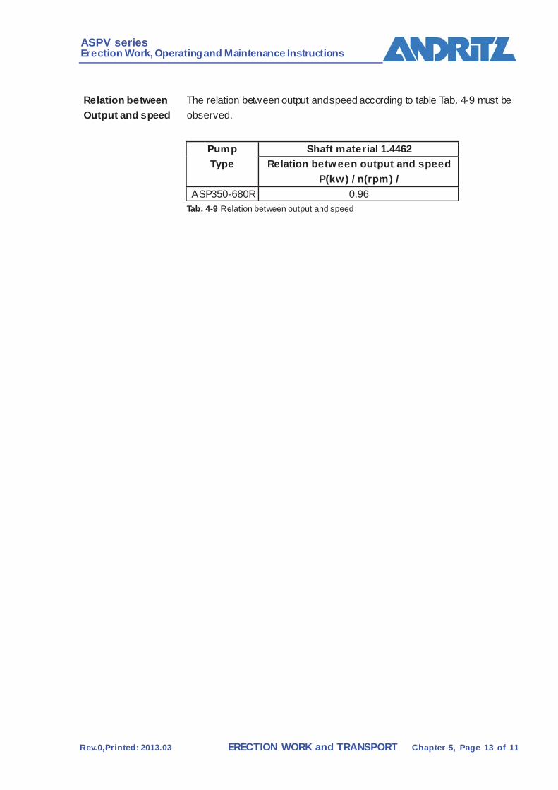
Relation between Output and speed
The relation between output and speed according to table Tab. 4-9 must be observed.
Pump Type
Shaft material 1.4462 Relation between output and speed
P(kw) / n(rpm) / ASP350-680R 0.96
Tab. 4-9 Relation between output and speed

ASPV series Erection Work, Operating and Maintenance Instructions
Rev.0,Printed: 2013.03 ERECTION WORK and TRANSPORT Chapter 5, Page 14 of 11
Technological Description
Definition The ASPV pump is used in continuous operation to pump clean liquids and various pulps used in the paper industry, with the aim of obtaining w ell mixed medium and of increasing the pressure.
Fig. 4-12 ASPV pump
Supply of medium
The medium to be pumped and mixed enters the volute casing through a suction pipe connected to the inlet f lange. In the suction channel the medium is split and then enters the suction area of the impeller in tw in f low and with a favourable flow pattern.
Pressure increase
The medium is sucked in by the tw in-flow impeller from both left and right (tw in-flow) in axial direction towards the center of the impeller.
In the impeller the medium undergoes radial acceleration, thus receiving speed energy, due to the rotational energy and the shape of the blades (changing from axial to radial). In the volute casing the speed energy is converted into pressure energy. The medium then enters the delivery pipe, which is connected to the outlet f lange.
ASPV series Erection Work, Operating and Maintenance Instructions
Rev.0,Printed: 2013.03 ERECTION WORK and TRANSPORT Chapter 5, Page 15 of 11
5.1 General This chapter describes certain steps for transport, storage and installation of the ASPV pump w hich may be the responsibility of the user.
Activities which are carried out by ANDRITZ, including w orks assembly, are not the subject of this description.
5.2 Safety regulations
DANGER
Disregarding the safety regulations may cause a risk to life and limb.
Disregarding the safety regulations may cause a risk to life and limb and damage to the machine or its components.
All safety instructions in this Chapter must be strictly observed.
General safety Instructions
All applicable accident prevention rules must be observed.
Do not exceed permissible crane loads and weights on lif ting gear and ropes/shackles. Secure loads against falling down.
Do not step or w alk below suspended loads. Standing below suspended loads is dangerous and thus forbidden.
Jerking must be avoided. This refers especially to the handling of pre-assembled machines.
Qualification of assigned personnel
Transport and unloading to be carried out by personnel specially familiar w ith such work.
Workers entrusted with lif ting and conveying equipment must have the required national qualif ication.
Start-up may only be carried out by trained, skilled w orkers.
Personal Protective apparel
The follow ing protective equipment must be w orn when carrying out start-up and transport work:
Hard hat Protective gloves
Protective shoes
Goggles
Tools Only use tools of a reputable brand and in good condition for any w ord performed on the ASPV pump.
ASPV series Erection Work, Operating and Maintenance Instructions
Rev.0,Printed: 2013.03 ERECTION WORK and TRANSPORT Chapter 5, Page 16 of 11
5.3 Haulage
DANGER
During transport of the ASPV pump or loading/unloading (pump may fall).
The loading equipment must bear the name of the manufacturer, the type of material and the permitted load!
Do not lift machine and transport crates except at the points marked For lifting by crane or forklift.
Do not step or walk below suspended loads.
Supply The ASPV pump is supplied pre-assemblied. Machine components and auxiliary material are packed in crates.
Transport sizes and weights are stated in the shipping documents.
Largest supply weights:
/ASPV PUMP/TECHNICAL DATA
Acceptance Check w hether supply is complete (against shipping documents and packing list) and in perfect condition.
In the event of transport damage or short supply, do not accept goods but notify forwarder and ANDRITZ’s shipping department.
If there is a hidden defect, notify forwarder and ANDRITZ’s shipping department w ithin two weeks.
ASPV series Erection Work, Operating and Maintenance Instructions
Rev.0,Printed: 2013.03 ERECTION WORK and TRANSPORT Chapter 5, Page 17 of 11
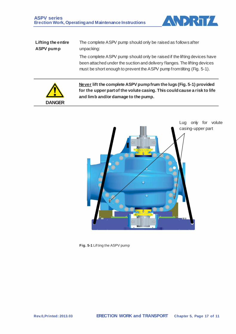
Lifting the entire ASPV pump
The complete ASPV pump should only be raised as follows after unpacking:
The complete ASPV pump should only be raised if the lif ting devices have been attached under the suction and delivery f langes. The lif ting devices must be short enough to prevent the ASPV pump from tilting (Fig. 5-1).
DANGER
Never lift the complete ASPV pump frum the lugs (Fig. 5-1) provided for the upper part of the volute casing. This could cause a risk to life and limb and/or damage to the pump.
Fig. 5-1 Lif ting the ASPV pump
Lug only for volute casing-upper part
ASPV series Erection Work, Operating and Maintenance Instructions
Rev.0,Printed: 2013.03 ERECTION WORK and TRANSPORT Chapter 5, Page 18 of 11
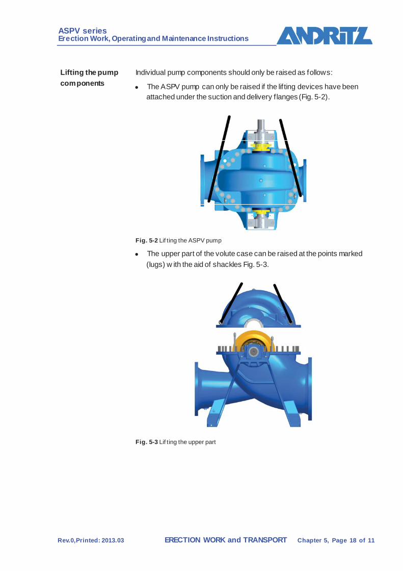
Lifting the pump components
Individual pump components should only be raised as follows:
The ASPV pump can only be raised if the lif ting devices have been attached under the suction and delivery f langes (Fig. 5-2).
Fig. 5-2 Lif ting the ASPV pump
The upper part of the volute case can be raised at the points marked (lugs) w ith the aid of shackles Fig. 5-3.
Fig. 5-3 Lif ting the upper part

ASPV series Erection Work, Operating and Maintenance Instructions
Rev.0,Printed: 2013.03 ERECTION WORK and TRANSPORT Chapter 5, Page 19 of 11
5.4 Storage
Short-term storage If the pump is to be stored for less than three months before erection work begins, please observe the following storage instructions.
Store the ASPV pump in a dry place, w ith suitable protection against dirt and corrosion.
Packing should not be removed until erection w ork begins. If there is no oil or grease in the bearing housing, it must be f illed w ith
oil or grease to protect the bearing assembly against corrosion.
Rotate the pump shaft manually every two weeks to prevent damage to the shaft bearing assembly.
Long-term storage If the pump is to be stored for more than three months before erection work begins, please observe the following storage instructions.
Store the ASPV pump in a dry place, w ith suitable protection against dirt and corrosion.
Incidentals should be protected against damage and unauthorized w ithdrawal by storing in a lockable room.
Drain any liquid from the ASPV pump. Rotate the pump shaft manually every two weeks to prevent damage to
the shaft bearing assembly.
If the ASPV pump has a casing of grey cast iron and a stuffing box packing, remove the packing cord and coat the stuff ing box body with an anti-rust agent.
If there is no oil or grease in the bearing housing, it must be f illed w ith oil or grease to protect the bearing assembly against corrosion.
CAUTION
The grease or oil in the bearing housing must be renewed before start-up. Anti-rust agents must be removed entirely.
ASPV series Erection Work, Operating and Maintenance Instructions
Rev.0,Printed: 2013.03 ERECTION WORK and TRANSPORT Chapter 5, Page 20 of 11
5.5 Installation
General Installation takes place in accordance with the sequence plan defined by ANDRITZ.
WARNING
Disregarding the sequence plan and the installation instructions may result in hazardous situations causing a danger to life and limb and in machine damage.
The sequence of erection work is important and must be strictly observed.
Implementation of the various steps must be documented in the certif icate of completion of erection w ork.
The sequence of erection work is shown in step-by-step tables. Individual activities are number in their order of precedence.
Preservation Those machine components which are not corrosion-resistant should be protected against corrosion with preserving grease.
The preservative grease need not be removed.
Required documentation at installation site
The follow ing supplementary documentation must be available at the beginning of erection w ork.
foundation and arrangement drawing
documentation on electrical, measuring and control equipment
packing lists for each individual delivery
Space requirement for erection work, operation and maintenance will be defined
together with the ANDRITZ representative in charge before the beginning of erection w ork.
Ambient temperature during erection w ork should not be less than 10-15˚ C.
ASPV series Erection Work, Operating and Maintenance Instructions
Rev.0,Printed: 2013.03 ERECTION WORK and TRANSPORT Chapter 5, Page 21 of 11
5.5.1 Erection of the ASPV pump
Foundation The foundation should be made according to ANDRITZ’s foundation plan.
The follow ing preparations have to be made prior to placing the ASPV pump on the foundation:
Mark axes and levels on the foundation.
Check the f inish of the foundation before beginning erection work.
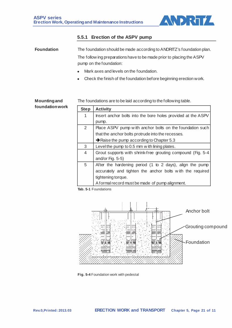
Mounting and foundation work
The foundations are to be laid according to the following table.
Step Activity 1 Insert anchor bolts into the bore holes provided at the ASPV
pump. 2 Place ASPV pump w ith anchor bolts on the foundation such
that the anchor bolts protrude into the recesses. Raise the pump according to Chapter 5.3
3 Level the pump to 0.5 mm w ith lining plates. 4 Grout supports with shrink-free grouting compound (Fig. 5-4
and/or Fig. 5-5) 5 After the hardening period (1 to 2 days), align the pump
accurately and tighten the anchor bolts w ith the required tightening torque. A formal record must be made of pump alignment.
Tab. 5-1 Foundations
Fig. 5-4 Foundation work with pedestal
Grouting compound
Foundation
Anchor bolt
ASPV series Erection Work, Operating and Maintenance Instructions
Rev.0,Printed: 2013.03 ERECTION WORK and TRANSPORT Chapter 5, Page 22 of 11
DANGER
Due to the ASPV pump or components of the ASPV pump falling during transport on installation site.
Raise ASPV pump according to the transport instructions in Chapter 5.3.
Do knot step or walk below suspended loads.
DANGER
Due to parts of the body being jammed or crushed during installation work.
Wear your personal protective apparel.
WARNING
Transport devices that are forgotten may result in risks to life and limb and in damage to the machine.
Remove all transport devices.

ASPV series Erection Work, Operating and Maintenance Instructions
Rev.0,Printed: 2013.03 ERECTION WORK and TRANSPORT Chapter 5, Page 23 of 11
5.5.2 Pipework
DANGER
If pipework is not mounted professionally.
This can result in risks to life and limb and in damage to the machine.
Under no circumstances should the ASPV pump be used to support a pipe!
WARNING
If there is risk of dangerous backflow after the pump is shut down, a reflux check device must be installed in the delivery pipe!
Support When planning the pipew ork, a supplement must be included for heat expansion.
Pipes should alw ays be mounted stress-free. During erection work ensure that the pipes are supported in such a w ay that no forces. vibrations or w eight can be transferred to the pump.
The suction and delivery pipes must be supported on a foundation so that the w eight of the pipe is not transferred to the ASPV pump (Fig. 5-6). The pipew ork is secured to the foundation with pipe clamps.
S = (1.2…..2) × d S = no. of pipe clamps
Fig. 5-6 Pipe f oundation
Pipe clamp Foundation Pipe clamp
ASPV series Erection Work, Operating and Maintenance Instructions
Rev.0,Printed: 2013.03 ERECTION WORK and TRANSPORT Chapter 5, Page 24 of 11
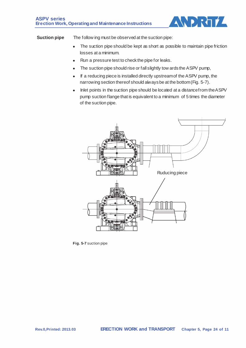
Suction pipe The follow ing must be observed at the suction pipe:
The suction pipe should be kept as short as possible to maintain pipe friction losses at a minimum.
Run a pressure test to check the pipe for leaks.
The suction pipe should rise or fall slightly tow ards the ASPV pump,
If a reducing piece is installed directly upstream of the ASPV pump, the narrowing section thereof should always be at the bottom (Fig. 5-7).
Inlet points in the suction pipe should be located at a distance from the ASPV pump suction f lange that is equivalent to a minimum of 5 times the diameter of the suction pipe.
Fig. 5-7 suction pipe
Ruducing piece
ASPV series Erection Work, Operating and Maintenance Instructions
Rev.0,Printed: 2013.03 ERECTION WORK and TRANSPORT Chapter 5, Page 25 of 11
5.6 Instruments Magnetic-inductive f low meter (690) (if included in scope of supply)
Instructions on installation and operation of the f low meter can be found in the enclosed description from the manufacturer.
This device must be adjusted under the supervision of Andritz personnel.

ASPV series Erection Work, Operating and Maintenance Instructions
Rev.0,Printed: 2013.03 ERECTION WORK and TRANSPORT Chapter 5, Page 26 of 11
5.7 Cold test
Prerequisites The following utilities must be available: Electric pow er
Water
Lubrication First f illing of lubricant and recording of all further lubrication
procedures according to the section headed “Lubrication” in the MAINTENANCE chapter.
WARNING
Machine may be damaged if inappropriate oil or grease grades are used as first filling.
Only use oils or greases with the properties listed in the lubrication CAUTION schedules.
Cold test Cold test is to be carried out together w ith the customer’s authorized representative.
The w ork steps listed in the cold test certif icate shall be carried out for the cold test, and documented.
/ATTACHMENT/CERTIFICATES AND BLOCK DIAGRAMS
Final inspection The customer and the erection w ork supervisor shall conduct a f inal inspection of the installation on completion of the cold tests.
Certificates
The follow ing certif icates are issued after completion of the ISO cold test
Cold test certif icate
Certif icate of completion of erection work.
Certif icates:
/ANNEX/CERTIFICATES AND BLOCK DIAGRAMS
ASPV series Erection Work, Operating and Maintenance Instructions
Rev.0,Printed: 2013.03 START-UP Chapter 6, Page 1 of 5
4 START-UP 6.1 General
Initial star-up of the ASPV pump shall be prepared and carried out by the Contractor or by ANDRITZ personnel. Start-up takes place in accordance w ith the start-up sequence plan and ANDRITZ’s start-up protocols.
During start-up practical machine training w ill also take place on the machine. Participants must have undergone theoretical training.
6.2 Safety regulations
DANGER
Disregarding the safety regulations may cause a risk to life and limb.
Disregarding the safety regulations may cause a risk to life and limb and damage to the machine or its components.
All safety instructions in this Chapter must be strictly observed.
General safety instructions
Start-up shall be carried out under the control of ANDRITZ’s start-up supervisor or by the Buyer.
All applicable accident prevention rules must be observed.
Qualification of assigned personnel
Start-up may only be carried out by trained, skill w orkers.
Personal protective apparel
The follow ing protective equipment must be w orn when carrying out start-up and erection work:
Hard hat
Protective shoes
Goggles Gloves must be w orn when handling aggressive media such as oil,
cleaning agent, chemicals, lubricants, white water, etc.
ASPV series Erection Work, Operating and Maintenance Instructions
Rev.0,Printed: 2013.03 START-UP Chapter 6, Page 2 of 5
6.3 Prerequisites for start-up The follow ing must be checked before start-up:
DANGER
Motor may be started up unintentionally.
Risk to life and limb and risk of damaging the machine or its DANGER components.
Take care that the motor cannot be started up!
Check for leaks The pump and pipew ork must be leak proof before start-up.
Leaks, particularly in the suction pipe, can reduce performance of the pump substantially and interfere with f illing of the pump before start-up.
Parts of the pump w hich are under pressure are not considered pressure vessels in terms of the off icial regulations on pressure vessels.
Sense of rotation of motor
Before start-up check that the motor is rotating in the right direction.
CAUTION
Before checking the sense of rotation of the motor, it is essential to remove the coupling spacer.
The motor must rotate in the direction of the arrow provided on the motor casing.
Free rotation The pump must be able to rotate freely. Here the tw o coupling halves should be separated from one another.
By rotating the pump end coupling half the operator can check whether the shaft can be rotated freely.
ASPV series Erection Work, Operating and Maintenance Instructions
Rev.0,Printed: 2013.03 START-UP Chapter 6, Page 3 of 5
Aligning the coupling
A further check should be performed to ensure that the coupling is properly aligned. Coupling alignment should then be verif ied in w riting.
For assembly and disassembly of the coupling, as well as the tolerances to be observed here, please see:
/ASPV PUMP/SUPPLIER DOCUMENTATION/COUPLING
Pump lubrication Before start-up, check the lubricant to be used for the pump an the drive bearing.
DANGER
Due to the pump not being lubricated correctly!
This can result in risks to life and limb and in damage to the machine.
The pump should never be operated without a suitable lubricant!
If the pump is kept in storage for a longer period before being put into operation, dirt and water may enter the pump kin the meantime. If there are substantial f luctuations in temperature, there may be some condensation.
Shaft seal and sealing water
Some parameters must be checked in order to ensure that the box mechanical seal is functioning well.
Only clean w ater from an external source should be used.
The maximum particle size of 80 microns must not be exceeded.
The maximum solids content of 2 mg/l (ppm) must not be exceeded. The stuff ing box mechanical seal must have an adequate supply of
sealing w ater. Throughput 3-5 l/min

ASPV series Erection Work, Operating and Maintenance Instructions
Rev.0,Printed: 2013.03 START-UP Chapter 6, Page 4 of 5
6.4 Start-up
CAUTION
Machine may be damaged by inappropriate starting.
All electric interlocks must be functional and checked.
Starting up the ASPV pump
If all preliminary requirements (see Chapter 6.3) have been fulf illed, the pump can then be started up according to the following table:
Prerequisites 1 Suction pipe and pump casing must be f illed w ith the medium. 2 The pump casing must be vented w ith the vent screw . 3 The shaft seal must have an adequate supply of sealing water. 4 There must be suff icient sealing water escaping from the stuff ing
box (30-80 Tropfen/min). 5 The mechanical seal must have a supply of sealing water. The
f low of sealing water should only be throttled at the outlet. 6 The valve in the suction pipe is fully open. 7 The valve in the delivery pipe is completely closed. 8 Start up pump and open the delivery side valve far enough to
obtain the desired f low rate. 9 Check stuff ing box to see whether enough liquid is coming out. If
not, the stuff ing box gland must be slackened right away. If the packing material still becomes too hot after the gland has been slackened, the operator must shut down the pump and look for the cause of the problem. When the stuff ing box has been running for approx. 10 minutes w ithout any problems, it can then be tightened again moderately. To set the stuff ing box, see Chapter on “Maintenance”.
Tab. 6-1 Starting up the ASPV pump
DANGER
If the pump runs dry!
This can result in risks to life and limb and in damage to the machine.
The pump should never be allowed to run dry under any circumstances , not even briefly.
ASPV series Erection Work, Operating and Maintenance Instructions
Rev.0,Printed: 2013.03 START-UP Chapter 6, Page 5 of 5
Fist trial run Functioning of the pump must be monitored carefully during the f irst few Hours in operation.
Particular attention must be paid to the following:
Temperature of the shaft seal Required amount of sealing w ater to the shaft seal
Bearing temperature and vibration
Pressure and f low rate in the pump
CAUTION
If there are any unusual noises, it is essential to look for the cause without delay and then eliminate the problem!
After start-up, the ASPV pump is handed over to the mill operator in a complete, reliable condition and ready for operation.
6.5 Certificates The follow ing certif icates must be completed and signed after start-up:
Start-up certif icate:
/ANNEX/CERTIFICATES AND BLOCK DIAGRAMS
Provisional acceptance certif icate:
/ANNEX/CERTIFICATES AND BLOCK DIAGRAMS
ASPV series Erection Work, Operating and Maintenance Instructions
Rev.0,Printed: 2011.07 OPERATION Chapter 7, Page 1 of 10
5 OPERATION 7.1 General
This chapter describes the activities required for starting, operating and stopping the ASPV pump. Possible malfunctions and troubleshooting methods are also presented.
7.2 Safety regulations
DANGER
Disregarding the safety regulations may cause a risk to life and limb.
Disregarding the safety regulations may cause a risk to life and limb and damage to the machine or its components.
All safety instructions in this Chapter must be strictly observed.
General safety instructions
All applicable accident prevention rules must be observed.
Operating the ASPV pump is not permitted w ithout all the required safety devices
Qualification of assigned personnel
The equipment may only be operated by qualif ied personnel.
Operating personnel must know where the emergency-off switches and the escape routes are located.
Operating personnel must have been instructed in the function and possible failure of machine monitoring equipment, and in carrying out maintenance and inspection w ork (shift log book, maintenance inspection records).
Personal Protective apparel
The follow ing personal protective equipment/apparel shall be used w hen performing w ork on the machine (e.g. troubleshooting):
Hard hat
Protective gloves
Protective shoes
Goggles
ASPV series Erection Work, Operating and Maintenance Instructions
Rev.0,Printed: 2011.07 OPERATION Chapter 7, Page 2 of 10
7.3 Control via DCS The ASPV pump can be started up and operated entirely from the DCS.
7.4 Starting
Prerequisites All preliminary requirements for start-up must be fulf illed before switching on the pump.
See:
/ASPV PUMP/START-UP/Preliminary requirements for start-up
Before starting the ASPV pump, the following parameters must be fulf illed:
Suction pipe and pump casing must be f illed w ith the medium.
The pump casing must be vented.
DANGER
If the pump runs dry!
This can result in risks to life and limb and in damage to the machine.
The pump should never be allowed to run dry under any circumstances, not even briefly.
The shaft seal must have an adequate supply of sealing water.
There must be sufficient sealing water escaping from the stuffing box. (30-80 drops/min)
The mechanical seal must have a supply of sealing w ater.
The valve in the delivery pipe is completely closed f irst of all.
CAUTION
Immediately after starting up the pump, open the valve in the delivery pipe far enough to obtain the desired flow rate.
The required flow rate must always be set using the valve on the delivery side!
If the operating pressure (see instruments) is not obtained within a short time, the pump must be stopped again and the cause of the problem found!
ASPV series Erection Work, Operating and Maintenance Instructions
Rev.0,Printed: 2011.07 OPERATION Chapter 7, Page 3 of 10
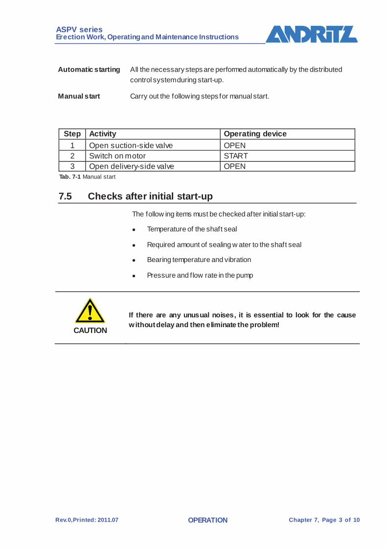
Automatic starting All the necessary steps are performed automatically by the distributed control system during start-up.
Manual start Carry out the following steps for manual start.
Step Activity Operating device
1 Open suction-side valve OPEN 2 Switch on motor START 3 Open delivery-side valve OPEN
Tab. 7-1 Manual start
7.5 Checks after initial start-up The follow ing items must be checked after initial start-up:
Temperature of the shaft seal
Required amount of sealing w ater to the shaft seal
Bearing temperature and vibration
Pressure and f low rate in the pump
CAUTION
If there are any unusual noises, it is essential to look for the cause without delay and then eliminate the problem!
ASPV series Erection Work, Operating and Maintenance Instructions
Rev.0,Printed: 2011.07 OPERATION Chapter 7, Page 4 of 10
7.6 Normal operation
DANGER
Do not operate without all safety devices ON.
While the pump is in operation the operating personnel should record the relevant data (shift record and data sheets).
Activities during normal operations
Once per shift The follow ing work has to be performed per shift in normal operation.
Component Activity ASPV pump, complete Visual check (sealing water, etc.)
Tab. 7-2 Activ ities to be performed in every shift
ASPV series Erection Work, Operating and Maintenance Instructions
Rev.0,Printed: 2011.07 OPERATION Chapter 7, Page 5 of 10
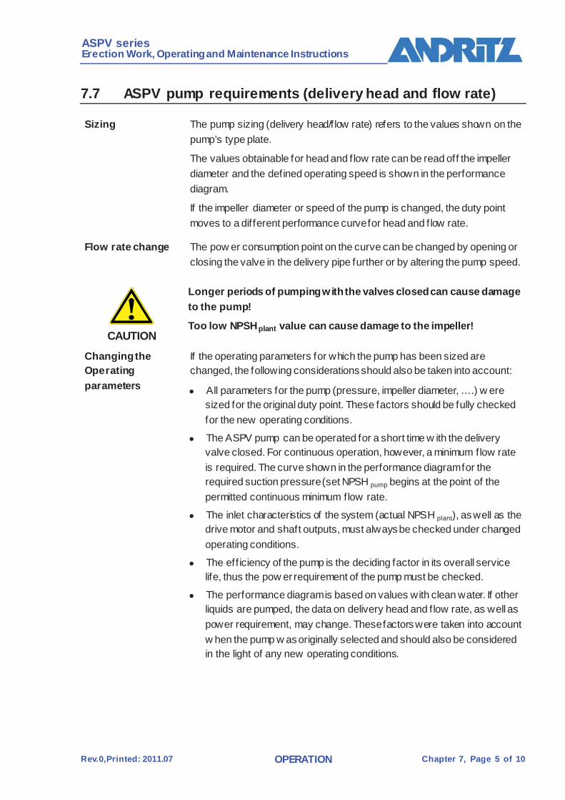
7.7 ASPV pump requirements (delivery head and flow rate)
Sizing The pump sizing (delivery head/f low rate) refers to the values shown on the pump’s type plate.
The values obtainable for head and f low rate can be read off the impeller diameter and the defined operating speed is shown in the performance diagram.
If the impeller diameter or speed of the pump is changed, the duty point moves to a different performance curve for head and f low rate.
Flow rate change The pow er consumption point on the curve can be changed by opening or closing the valve in the delivery pipe further or by altering the pump speed.
CAUTION
Longer periods of pumping with the valves closed can cause damage to the pump!
Too low NPSH plant value can cause damage to the impeller!
Changing the Operating parameters
If the operating parameters for which the pump has been sized are changed, the following considerations should also be taken into account:
All parameters for the pump (pressure, impeller diameter, ….) w ere sized for the original duty point. These factors should be fully checked for the new operating conditions.
The ASPV pump can be operated for a short time w ith the delivery valve closed. For continuous operation, however, a minimum flow rate is required. The curve shown in the performance diagram for the required suction pressure (set NPSH pump begins at the point of the permitted continuous minimum flow rate.
The inlet characteristics of the system (actual NPSH plant), as well as the drive motor and shaft outputs, must always be checked under changed operating conditions.
The eff iciency of the pump is the deciding factor in its overall service life, thus the pow er requirement of the pump must be checked.
The performance diagram is based on values with clean water. If other liquids are pumped, the data on delivery head and f low rate, as well as power requirement, may change. These factors were taken into account w hen the pump w as originally selected and should also be considered in the light of any new operating conditions.

ASPV series Erection Work, Operating and Maintenance Instructions
Rev.0,Printed: 2011.07 OPERATION Chapter 7, Page 6 of 10
7.8 Stopping
Automatic stop When using the group stop, all necessary steps are carried out automatically w ith the DCS.
Manual stop Carry out the following steps for manual stop.
Stop the pump motor
Close the valve in the delivery pipe
Close the valve in the suction pipe , if necessary
Allow the pressure to escape from the pump Close the inlet for the sealing liquid
CAUTION
If there is a danger of the pump liquid freezing, the pump and pipe should be emptied!

ASPV series Erection Work, Operating and Maintenance Instructions
Rev.0,Printed: 2011.07 OPERATION Chapter 7, Page 7 of 10
7.9 Operating malfunctions and troubleshooting
Malfunction Possible cause Remedy Pump is not pumping medium
Insuff icient pre-filling of pump Steam bubbles forming in suction pipe (NPSH plant)
Repeat pre-f illing of the pump and suction pipe
Pressure difference between inlet pressure and steam pressure is too low
Check the suction pipe
Air entering the suction pipe, suction port or shaft seal
Check the suction pipe and the shaft seal
Suction pipe, suction valve or impeller are clogged
Check the suction pipe and the entire pump for clogging
Speed too low Check the speed requirements Flow resistance in the pipe is greater than the delivery head generated at the pump
Check the resistance in the pipe
Insufficient delivery head Unexpected air/gas content in pumping medium
Contact ANDRITZ for further instructions
Unexpectedly high viscosity in the medium
Contact ANDRITZ for further instructions
Suction pipe, suction valve or impeller are clogged
Check the suction pipe and the entire pump for clogging
Speed too low Check the speed requirements Wrong direction of rotation Change sense of rotation of the
motor Flow resistance in the pipe is greater than the delivery head generated at the pump
Check and minimize the pipe resistance
Pump parts coming into contact with pressure are worn, damaged or clogged
Check the pump and change any w orn or damaged parts if necessary
Delivery-side valve partly open or closed
Open valve
Tab. 7-3 Operating malf unctions and troubleshooting

ASPV series Erection Work, Operating and Maintenance Instructions
Rev.0,Printed: 2011.07 OPERATION Chapter 7, Page 8 of 10
Malfunction Possible cause Remedy
Inadequate or irregular flow rate
Steam bubbles forming in the suction pipe
Repeat pre-f illing of the pump and suction pipe
Wrong direction of rotation Change sense of rotation of the motor Net positive suction height (NPSH plant ) is too low
Check whether the suction valve is fully open and the suction pipe clear
Pressure difference between NPSH plant and NPSH pump is too low
Check the suction pipe
Air inlet in the suction pipe, suction port or shaft seal
Check the suction pipe and the shaft seal
Unexpected air/gas content in pumping medium
Contact ANDRITZ for further instructions
Unexpectedly high viscosity in the medium
Contact ANDRITZ for further instructions
Suction pipe, suction valve or impeller are clogged
Check the suction pipe and the entire pump for clogging
Flow resistance in the pipe is greater than the delivery head generated at the pump
Check the resistance in the pipe
Pump parts coming into contact w ith pressure are worn, damaged or clogged
Check the pump and change any w orn or damaged parts if necessary
High power loss Speed too high Check the motor speed Wrong direction of rotation Check the sense of rotation of the
motor Flow resistance in the pipe is greater than the delivery head generated at the pump
Check the resistance in the pipe
Unexpected specific gravitation in pumping medium
Contact ANDRITZ for further instructions
Unexpectedly high viscosity in the medium
Contact ANDRITZ for further instructions
Bent or eccentric pump shaft Replace the pump shaft and bearing Rotating objects or pump parts causing friction in the pump
Disassemble and check the inside of the pump
Pump parts coming into contact w ith pressure are worn, damaged or clogged
Check the pump and change any w orn or damaged parts if necessary
Tab. 7-3 Operating malf unctions and troubleshooting
ASPV series Erection Work, Operating and Maintenance Instructions
Rev.0,Printed: 2011.07 OPERATION Chapter 7, Page 9 of 10
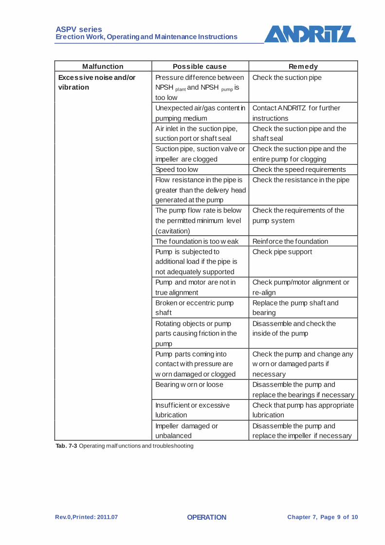
Malfunction Possible cause Remedy
Excessive noise and/or vibration
Pressure difference between NPSH plant and NPSH pump is too low
Check the suction pipe
Unexpected air/gas content in pumping medium
Contact ANDRITZ for further instructions
Air inlet in the suction pipe, suction port or shaft seal
Check the suction pipe and the shaft seal
Suction pipe, suction valve or impeller are clogged
Check the suction pipe and the entire pump for clogging
Speed too low Check the speed requirements Flow resistance in the pipe is greater than the delivery head generated at the pump
Check the resistance in the pipe
The pump flow rate is below the permitted minimum level (cavitation)
Check the requirements of the pump system
The foundation is too w eak Reinforce the foundation Pump is subjected to additional load if the pipe is not adequately supported
Check pipe support
Pump and motor are not in true alignment
Check pump/motor alignment or re-align
Broken or eccentric pump shaft
Replace the pump shaft and bearing
Rotating objects or pump parts causing friction in the pump
Disassemble and check the inside of the pump
Pump parts coming into contact with pressure are w orn damaged or clogged
Check the pump and change any w orn or damaged parts if necessary
Bearing w orn or loose Disassemble the pump and replace the bearings if necessary
Insuff icient or excessive lubrication
Check that pump has appropriate lubrication
Impeller damaged or unbalanced
Disassemble the pump and replace the impeller if necessary
Tab. 7-3 Operating malf unctions and troubleshooting

ASPV series Erection Work, Operating and Maintenance Instructions
Rev.0,Printed: 2011.07 OPERATION Chapter 7, Page 10 of 10
Malfunction Possible cause Remedy
Excessive wear on bearing
Pump and motor are not in true alignment
Check pump/motor alignment or re-align
Broken or eccentric pump shaft Replace the pump shaft and bearing Rotating objects or pump parts causing friction in the pump
Disassemble and check the inside of the pump
Impeller damaged or unbalanced
Disassemble the pump and replace the impeller if necessary
Insuff icient or excessive lubrication
Check that pump has appropriate lubrication
Bearing not installed properly or dirty
Replace bearing assembly if necessary and check the lubricating system for contamination
Pump overheating/jamming
Delivery-side valve closed Open valve Insuff icient pre-filling of pump Repeat pre-f illing of the pump and
suction pipe Pressure difference between NPSH plant and NPSH pump is too low
Check the suction pipe
The pump flow rate is below the permitted minimum level (cavitation)
Check the requirements of the pump system
Pump and motor are not in true alignment
Check pump/motor alignment or re-align
Bearing w orn or loose Disassemble the pump and replace the bearings if necessary
Broken or eccentric pump shaft Replace the pump shaft and bearing Impeller damaged or unbalanced
Disassemble the pump and replace the impeller if necessary
Rotating objects or pump parts causing friction in the pump
Disassemble and check the inside of the pump
Flow resistance in the pipe is greater than the delivery head generated at the pump
Check and minimize the pipe resistance
Tab. 7-3 Operating malf unctions and troubleshooting
ASPV series Erection Work, Operating and Maintenance Instructions
Rev.0,Printed: 2013.03 MAINTENANCE Chapter 8, Page 1 of 28
6 MAINTENANCE 8.1 General
This chapter describes the maintenance and upkeep of the ASPV pump, w hich is the responsibility of the machine/mill operator.
All activities mentioned in this chapter must be performed at the correct time.
The ANDRITZ service department is at your disposal for troubleshooting, as w ell as for extensive maintenance and repair work. (/ASPV PUMP/INTRODUCTION)
Workers trained and authorized by ANDRITZ may also carry out repairs on site after obtaining consent from AAG.
8.2 Safety regulations
DANGER
Disregarding the safety regulations may cause a risk to life and limb.
Disregarding the safety regulations may cause a risk to life and limb and damage to the machine or its components.
All safety instructions in this Chapter must be strictly observed.
General safety Instructions
All applicable accident prevention rules must be observed.
Suff icient spaced for maintenance work must be included right aw ay in the arrangement drawing.
Maintenance and upkeep must not be performed when the machine is in operation.
Do not exceed permissible crane loads and weights on lif ting gear and ropes/shackles. Secure loads against falling down.
Do not step or w alk below suspended loads. Standing below suspended loads is dangerous and thus forbidden.
Machine must be thoroughly cleaned before carrying out any maintenance w ork.
Use only genuine spare parts.
Energy supply Before beginning any maintenance or repair w ork the operator must disconnect the energy supply to all drives securely. This can be achieved w ith a maintenance switch, lockable racks in the MCC, or w ith other suitable measures that comply w ith the safety regulations.

ASPV series Erection Work, Operating and Maintenance Instructions
Rev.0,Printed: 2013.03 MAINTENANCE Chapter 8, Page 2 of 28
Qualification of assigned personnel
Maintenance and upkeep must be carried out by trained and skilled personnel.
Work on the electrical equipment must be carried out without exception by skilled electricians.
Personal protective apparel
The follow ing protective equipment must be w orn when carrying out cleaning and maintenance:
Hard hat
Protective gloves Protective shoes
Goggles
Tools Only use tools of a reputable brand and in good condition for any w ork performed on the ASPV pump.
8.3 Regular maintenance
CAUTION
Regular monitoring of operations and performance of the ASPV pump will allow the operator to detect any need for maintenance and repairs in good time. This guarantees a high level of efficiency, a trouble-free operating sequence, and minimizes the maintenance costs!
The discharge pressure, f low rate and power consumption should be monitored continuously.
For machines operating continuously (24 hours/day, 7 days/week), a prescheduled maintenance period every two weeks is recommended.
During these periods the machine should be shut dow n, thoroughly cleaned and checked for wear.
Machines operating less than 24 hours per day should be subjected to these routine checks and cleaned at each stoppage.
General machine Checks
The follow ing checks should be made w hen the machine is at a standstill:
Component Checks Shaft seal Leaks and w ear Bearing Lubricant quantity (oil level) Static seals Leaks Coupling Wear on the coupling pads Complete pump Visual check
Tab. 8-1 General machine checks

ASPV series Erection Work, Operating and Maintenance Instructions
Rev.0,Printed: 2013.03 MAINTENANCE Chapter 8, Page 3 of 28
In the course of general machine checks all additional units should also be checked to guarantee that the entire plant functions satisfactorily. For these checks, the attached manufacturer’s maintenance and upkeep instructions must be observed.
/FANPUMP/SUPPLIER DOCUMENTATION
Malfunctions and unforeseen modif ications found during these checks must be eliminated immediately
Cleaning Clean the fan by hosing dow n or brushing when it is at a standstill.
CAUTION
Do not use caustic agents fro cleaning.
Make sure no water, steam or other cleaning medium enters electrical plant components.

ASPV series Erection Work, Operating and Maintenance Instructions
Rev.0,Printed: 2013.03 MAINTENANCE Chapter 8, Page 4 of 28
8.4 Maintenance schedule
In addition to the w ork outlined below, maintenance and word required for normal operations (/ASPV PUMP/OPERATION/NORMAL OPEATION) must also be carried out.
Monthly The follow ing maintenance work is to be carried out at monthly intervals.
Component Activity Bearings Check temperature
Measure vibrations Oil level Grease level is to be checked Check for strange noises
Volute casing (upper part – low er part)
Check for corrosion and wear
Shaft w ith bearing Check for smooth running Coupling Check alignment
Check pads for wear Stuff ing box seal Mechanical seal
Check for leaks Check for wear
Pipew ork Check for leaks Complete pump Check for leaks
Cleaning Tab. 8-2 Monthly maintenance work
Semi-annually The follow ing maintenance work is to be carried out at 6-monthly intervals
Component Activity Complete pump Check mounting of pump on the
foundation Motor Check mounting of motor on the
foundation Tab. 8-3 6-monthly maintenance work
Annually The follow ing maintenance work is to be carried out at annual intervals.
Component Activity Complete pump Complete service according to
instructions form ANDRITZ (Oil change Grease change, impeller check, etc.)
Tab. 8-4 Annual maintenance work
ASPV series Erection Work, Operating and Maintenance Instructions
Rev.0,Printed: 2013.03 MAINTENANCE Chapter 8, Page 5 of 28
8.5 Fasteners
Screw material Bolts and screws are manufactured in several classes of material. The heads of these screws and bolts are marked to identify the strength class of the screw or bolt. Damaged or lost fasters should only be replaced with fasteners of the same material.
Check Unless they are suitably tightened, screws can work loose or fail under operating conditions. In the course of maintenance work, all fastening screws must be checked.
During the f irst six months: every 2 to 21/2 months
After the f irst six months: semi-annually
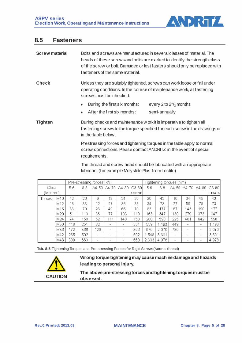
Tighten During checks and maintenance w ork it is imperative to tighten all fastening screws to the torque specified for each screw in the drawings or in the table below.
Prestressing forces and tightening torques in the table apply to normal screw connections. Please contact ANDRITZ in the event of special requirements.
The thread and screw head should be lubricated with an appropriate lubricant (for example Molyslide Plus from Loctite).
Tab. 8-5 Tightening Torques and Pre-stressing Forces for Rigid Screws(Normal thread)
CAUTION
Wrong torque tightening may cause machine damage and hazards leading to personal injury.
The above pre-stressing forces and tightening torques must be observed.
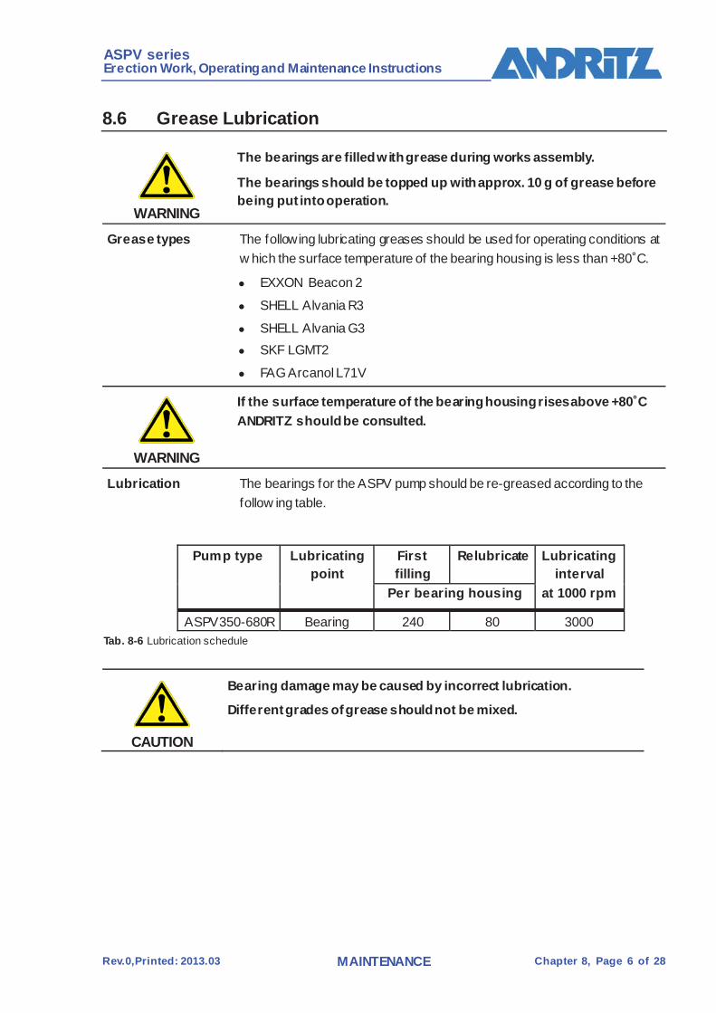
ASPV series Erection Work, Operating and Maintenance Instructions
Rev.0,Printed: 2013.03 MAINTENANCE Chapter 8, Page 6 of 28
8.6 Grease Lubrication
WARNING
The bearings are filled w ith grease during works assembly.
The bearings should be topped up with approx. 10 g of grease before being put into operation.
Grease types The following lubricating greases should be used for operating conditions at w hich the surface temperature of the bearing housing is less than +80˚C.
EXXON Beacon 2
SHELL Alvania R3
SHELL Alvania G3 SKF LGMT2
FAG Arcanol L71V
WARNING
If the surface temperature of the bearing housing rises above +80˚C ANDRITZ should be consulted.
Lubrication The bearings for the ASPV pump should be re-greased according to the follow ing table.
Pump type Lubricating
point First filling
Relubricate Lubricating interval
at 1000 rpm Per bearing housing
ASPV350-680R Bearing 240 80 3000 Tab. 8-6 Lubrication schedule
CAUTION
Bearing damage may be caused by incorrect lubrication.
Different grades of grease should not be mixed.

ASPV series Erection Work, Operating and Maintenance Instructions
Rev.0,Printed: 2013.03 MAINTENANCE Chapter 8, Page 7 of 28
Grease change The old grease should be cleaned off the bearing housing each time the rotor unit is removed (annual service). After re-assembly the bearing should be given a f illing of fresh grease.
The grease in the bearings is to be changed according to the ̀ following table.
Fig. 8-2 Grease lubricating at the bearing
Step Activity 1 Remov e top section of bearing housing (352)
2 Remov e the left and right bearing cover(421.1,421.2)
3 Remov e grease f rom the bottom section of the bearing housing (351).
4 Re-assemble bearing in rev erse order.
5 Top up grease according to Tab. 8-9 at the grease nipple (636).
Tab. 8-7 Grease change
ASPV series Erection Work, Operating and Maintenance Instructions
Rev.0,Printed: 2013.03 MAINTENANCE Chapter 8, Page 8 of 28
8.7 Aliging the coupling The coupling alignment must be checked after each of the following
assembly steps and corrected if necessary.
In particular:
After mounting and before grouting in the pump
After grouting in After installing the pipew ork
After the trial run w ith water
If the alignment changes during production, the pump can also be aligned at operating temperature.
Aligning tolerances Permitted tolerances
/ASPV PUMP/SUPPLIER DOCUMENTATION/COUPLING
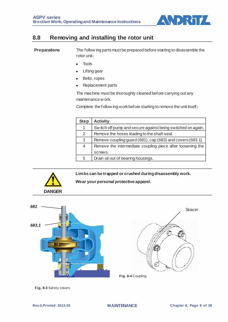
ASPV series Erection Work, Operating and Maintenance Instructions
Rev.0,Printed: 2013.03 MAINTENANCE Chapter 8, Page 9 of 28
8.8 Removing and installing the rotor unit
Preparations The follow ing parts must be prepared before starting to disassemble the rotor unit:
Tools
Lif ting gear
Belts, ropes Replacement parts
The machine must be thoroughly cleaned before carrying out any maintenance w ork.
Complete the follow ing work before starting to remove the unit itself:
Step Activity
1 Sw itch off pump and secure against being switched on again. 2 Remove the hoses leading to the shaft seal. 3 Remove coupling guard (681), cap (683) and covers (683.1). 4 Remove the intermediate coupling piece after loosening the
screws. 5 Drain oil out of bearing housings.
DANGER
Limbs can be trapped or crushed during disassembly work.
Wear your personal protective apparel.
Fig. 8-3 Saf ety covers
Fig. 8-4 Coupling
683.1
681 Spacer

ASPV series Erection Work, Operating and Maintenance Instructions
Rev.0,Printed: 2013.03 MAINTENANCE Chapter 8, Page 10 of 28
Removing the pump unit
Remove the motor and the pump unit according to the follow ing table:
Step Activity 1 Loosen the screws between the base frame to the pump unit .Lift the
pump unit according to Fig. 8-6 and keep the pump unit horizontal according to Fig. 8-7
Tab. 8-8 Remov ing the motor and the pump unit
Fig. 8-5 Removing the pump unit
Fig. 8-6 Lift the pump unit
Fig. 8-7 keep the pump unit horizontal

ASPV series Erection Work, Operating and Maintenance Instructions
Rev.0,Printed: 2013.03 MAINTENANCE Chapter 8, Page 11 of 28
Removing the volute casing upper part
Remove the upper part of pump according to the following table:
Step Activity 1 Loosen the screws (901.2) at the stuffing box gland(452) 2 Loosen hexagon nuts (920.1) at the upper part of the volute casing
(102.2), remove the taper pins (560.1) and raise the upper part of the volute casing.
Raise the upper part of the volute casing according to Fig. 8-5.
Tab. 8-9 Remov ing the v olute casing upper part
Removing the rotor unit
The rotor unit comprises the impeller (232), the shaft (211), the bearings, and the sealing units.
Remove the rotor unit according to the following table: The activities listed in the table are to be carried out on both sides of the pump.
Step Activity
1 Loosen the screws (902.3) at the stuffing box gland(452)
2 Loosen hexagon nuts (920.1) at the upper part of the volute casing (102.2), remove the taper pins (560.1) and raise the upper part of the volute casing.
Raise the upper part of the volute casing according to Fig. 8-5.
3 Loosen hexagon nuts (920.2) at the upper part of the bearing casing (352), remove the taper pins (560.4) and raise the upper part of the bearing casing.
4 Lift the rotor unit out of the lower part of the volute casing according to Fig. 8-7 and place on a suitable support (wooden).
5 Dismantle the coupling according to the instructions issued by the coupling manufacturer.
/ASP PUMP/SUPPLIER DOCUMENTATION/COUPLING
Tab. 8-10 Remov ing the rotor unit
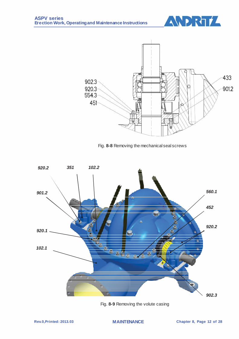
ASPV series Erection Work, Operating and Maintenance Instructions
Rev.0,Printed: 2013.03 MAINTENANCE Chapter 8, Page 12 of 28
Fig. 8-8 Removing the mechanical seal screws
Fig. 8-9 Removing the volute casing
560.1
102.2 351 920.2
920.1 920.2
901.2
102.1
902.3
452
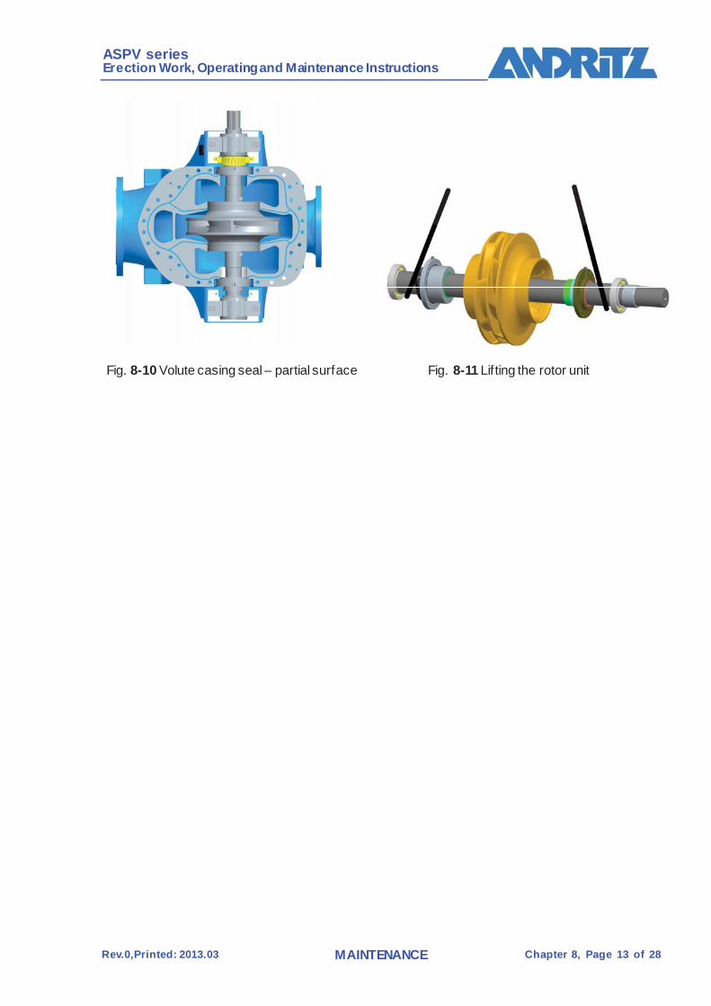
ASPV series Erection Work, Operating and Maintenance Instructions
Rev.0,Printed: 2013.03 MAINTENANCE Chapter 8, Page 13 of 28
Fig. 8-10 Volute casing seal – partial surface Fig. 8-11 Lifting the rotor unit

ASPV series Erection Work, Operating and Maintenance Instructions
Rev.0,Printed: 2013.03 MAINTENANCE Chapter 8, Page 14 of 28
Installation of the rotor unit
Proceed according to the follow ing table when installing the rotor unit
Step Activity 1 Replace O-rings (412.6) in the retaining ring and lift the rotor unit into the
lower part of the v olute casing (102.1) according to Fig. 8-7.
2 Ensure that all loose parts fit into the positions where they belong. The
bore holes in the wear rings (502) must fit exactly ov er the hexagon socket
head cap screws in the lower part of the v olute casing (anti-torsion dev ice
f or the wear rings).
3 Clean the sealing surf aces of the bearing housing (upper and lower part)
and seal with surf ace seal (400.2).
4 Raise upper part of bearing housing (352), insert taper pins (560.4) and
screw onto the lower part of the bearing housing with the hexagon nuts
(920.2).
5 Sealing surfaces of the volute casing (upper and lower part )are to be
cleaned.
6 APTFE surface seal is to be applied to the contact surf aces of the lower
part of the v olute casing (102.1) according to Fig. 8-6.
Seal ty pe: GORE-TEX,DEO6 3.2 × 0.7
Fig. 8-6 should also be sealed with a surf ace seal (400.1 – Loctite 510).
7 Mount the upper part of the v olute casing (102.2) carefully with the taper
pins (560.1) inserted.
(The taper pins are intended as a guide).
8 Tighten hexagon nuts (920.1) of the v olute casing upper part (102.2)
alternately.
See Tab. 8-5 f or tightening torques.
9 Assemble the coupling according to the instructions issued by the coupling
manuf acturer.
/SmartFlow PUMP/SUPPLIER DOCUMENTATION/COUPLING
Tab. 8-11 Installing the rotor unit
After installing the rotor unit as described above, the activities listed in Tab.8-11 should be carried out in reverse order.
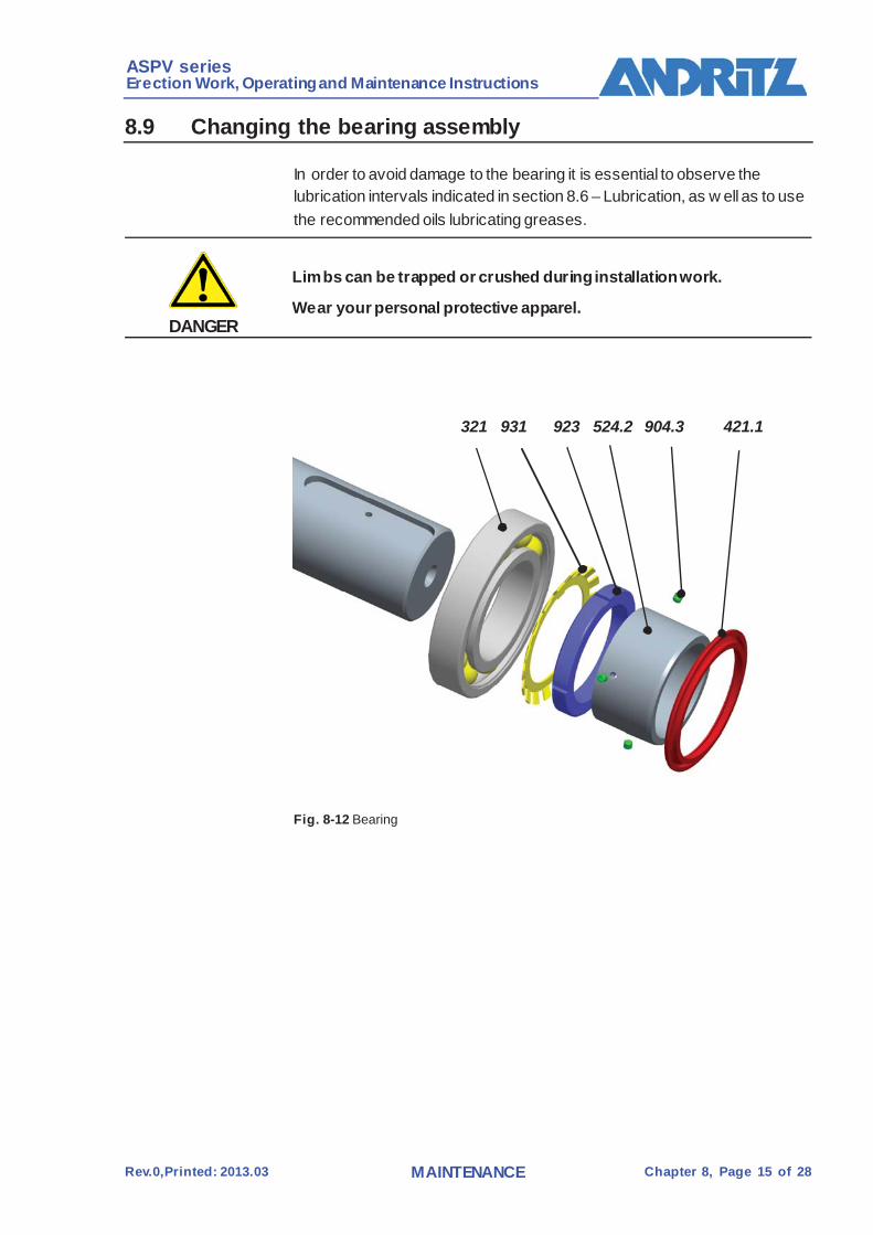
ASPV series Erection Work, Operating and Maintenance Instructions
Rev.0,Printed: 2013.03 MAINTENANCE Chapter 8, Page 15 of 28
8.9 Changing the bearing assembly In order to avoid damage to the bearing it is essential to observe the
lubrication intervals indicated in section 8.6 – Lubrication, as w ell as to use the recommended oils lubricating greases.
DANGER
Limbs can be trapped or crushed during installation work.
Wear your personal protective apparel.
Fig. 8-12 Bearing
321 421.1 931 923 524.2 904.3
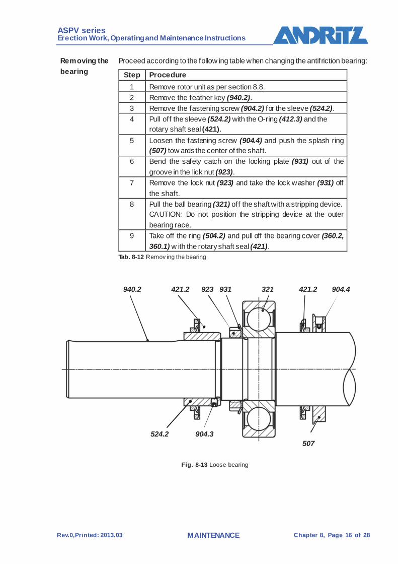
ASPV series Erection Work, Operating and Maintenance Instructions
Rev.0,Printed: 2013.03 MAINTENANCE Chapter 8, Page 16 of 28
Removing the bearing
Proceed according to the follow ing table when changing the antifriction bearing:
Step Procedure 1 Remove rotor unit as per section 8.8. 2 Remove the feather key (940.2). 3 Remove the fastening screw (904.2) for the sleeve (524.2). 4 Pull off the sleeve (524.2) with the O-ring (412.3) and the
rotary shaft seal (421). 5 Loosen the fastening screw (904.4) and push the splash ring
(507) tow ards the center of the shaft. 6 Bend the safety catch on the locking plate (931) out of the
groove in the lick nut (923). 7 Remove the lock nut (923) and take the lock washer (931) off
the shaft. 8 Pull the ball bearing (321) off the shaft with a stripping device.
CAUTION: Do not position the stripping device at the outer bearing race.
9 Take off the ring (504.2) and pull off the bearing cover (360.2, 360.1) w ith the rotary shaft seal (421).
Tab. 8-12 Remov ing the bearing
Fig. 8-13 Loose bearing
524.2
940.2
904.3 507
421.2 923 931 321 421.2 904.4
ASPV series Erection Work, Operating and Maintenance Instructions
Rev.0,Printed: 2013.03 MAINTENANCE Chapter 8, Page 17 of 28
Installing the bearing
Proceed according to the follow ing table when installing the antifriction bearing:
Step Procedure 1 Loosen the fastening screw (904.4) for the splash ring (507)
and push the splash ring tow ards the center of the shaft. 2 Push on the bearing cover (360,1, 360.2) with the new rotary
shaft seal (421) up to the splash ring. 3 Replace ball bearing (321). 4 Heat the ball bearings (321) according to the instructions from
the bearing manufacturer (approx. 80̊ C) and push onto the shaft as far as the ring (504.2).
5 Mount the lock nut (923) w ith the lock washer (931) and tighten (by turning to the right).
6 Bend the safety catch on the locking plate (931) into the groove in the lock nut (923).
7 Pull on the sleeve (524.2) using the O-ring (412.3) coated with silicone grease until it is resting on the shoulder of the shaft.
8 Tighten the fastening screw (904.2) for the sleeve (524.2). 9 Mount the feather key (940.2). 1 Install rotor unit as per section 8.8.
After installing the rotor unit, the splash ring (507) must be tightened so that is has 3 mm clearance to the bearing cover.
Caution: On the f ixed bearing side, the f ixed ring (504.1) is to be installed in the bearing housing.
Tab. 8-13 Mounting the antif riction Bearing
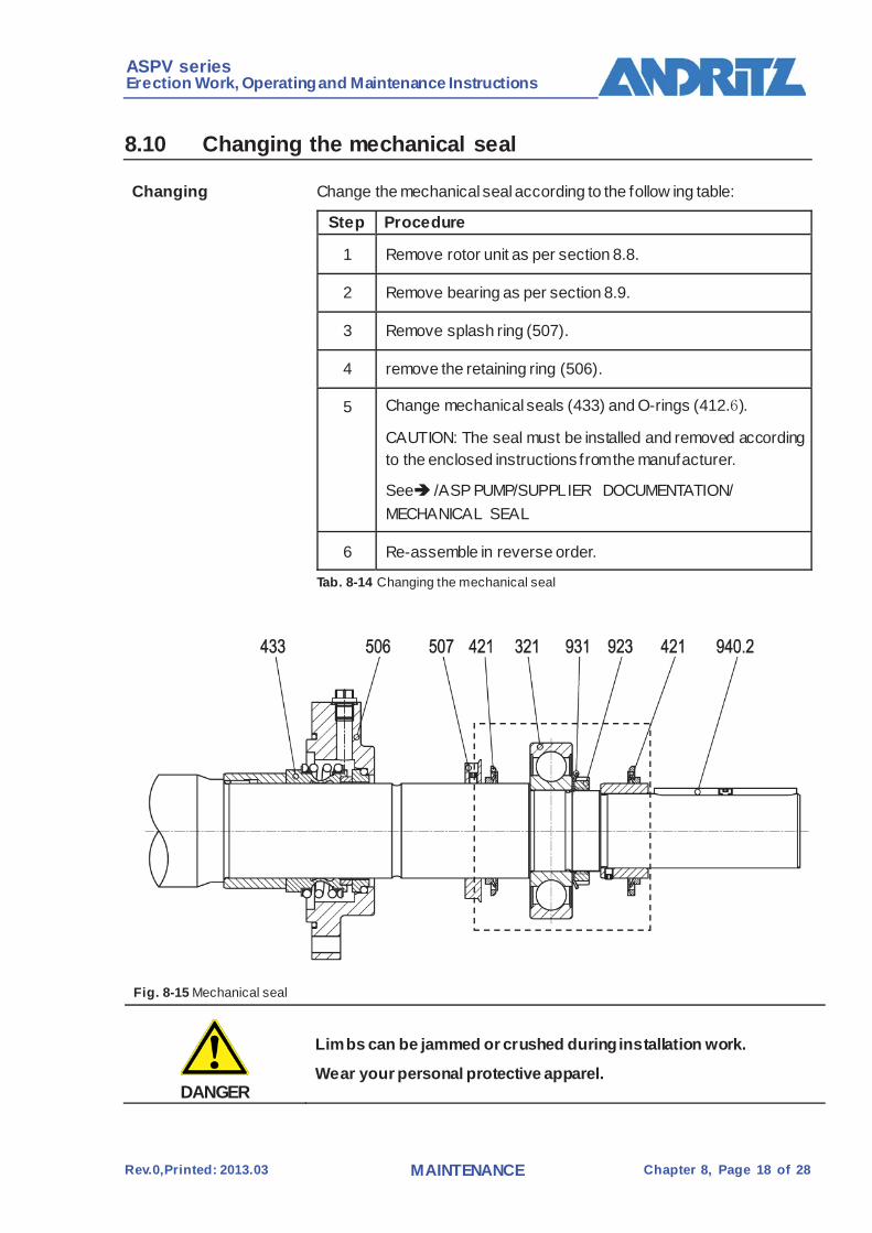
ASPV series Erection Work, Operating and Maintenance Instructions
Rev.0,Printed: 2013.03 MAINTENANCE Chapter 8, Page 18 of 28
8.10 Changing the mechanical seal
Changing Change the mechanical seal according to the follow ing table:
Step Procedure
1 Remove rotor unit as per section 8.8.
2 Remove bearing as per section 8.9.
3 Remove splash ring (507).
4 remove the retaining ring (506).
5 Change mechanical seals (433) and O-rings (412.6).
CAUTION: The seal must be installed and removed according to the enclosed instructions from the manufacturer.
See /ASP PUMP/SUPPLIER DOCUMENTATION/ MECHANICAL SEAL
6 Re-assemble in reverse order.
Tab. 8-14 Changing the mechanical seal
Fig. 8-15 Mechanical seal
DANGER
Limbs can be jammed or crushed during installation work.
Wear your personal protective apparel.
ASPV series Erection Work, Operating and Maintenance Instructions
Rev.0,Printed: 2013.03 MAINTENANCE Chapter 8, Page 19 of 28
8.11 Removing and installing the impeller
DANGER
Limbs can be trapped or crushed during disassembly work.
Do not touch the shaft with your hands while pushing the impeller off!
DANGER
Injury at the impeller!
Impellers may have very sharp edges, particularly when they are worn.
Wear protective clothing and gloves!
Use a hydraulic pump that can build up a pressure of at least 700 bar to push the impeller off. (PA-133, THAP-150 from SKF).
DANGER
Beware of high pressure in the hydraulic system!
Hydraulic pumps and pipes are under high pressure.
Wear your personal protective apparel!
Always make sure that the connections and joints are in perfect condition!
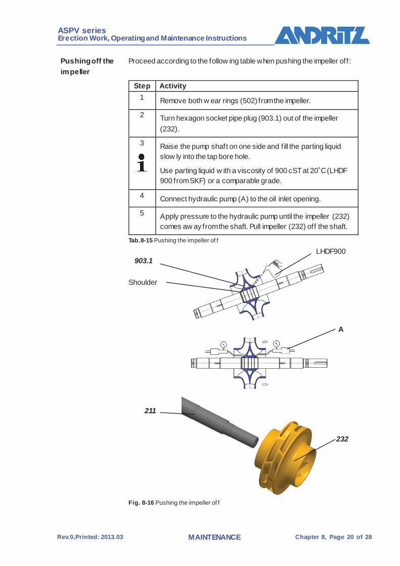
ASPV series Erection Work, Operating and Maintenance Instructions
Rev.0,Printed: 2013.03 MAINTENANCE Chapter 8, Page 20 of 28
Pushing off the impeller
Proceed according to the follow ing table when pushing the impeller off:
Step Activity
1 Remove both w ear rings (502) from the impeller.
2 Turn hexagon socket pipe plug (903.1) out of the impeller (232).
3
Raise the pump shaft on one side and f ill the parting liquid slow ly into the tap bore hole.
Use parting liquid w ith a viscosity of 900 cST at 20˚C (LHDF 900 from SKF) or a comparable grade.
4 Connect hydraulic pump (A) to the oil inlet opening.
5 Apply pressure to the hydraulic pump until the impeller (232) comes aw ay from the shaft. Pull impeller (232) off the shaft.
Tab.8-15 Pushing the impeller of f
Fig. 8-16 Pushing the impeller of f
Shoulder
903.1 LHDF900
A
211
232
ASPV series Erection Work, Operating and Maintenance Instructions
Rev.0,Printed: 2013.03 MAINTENANCE Chapter 8, Page 21 of 28
Installation of the Impeller
Preliminary requirements:
Clean room w ith no draft, temperature +20˚C
Lif ting device, e.g. crane, for manipulating the shaft Ring bolt for manipulating the shaft
Liquid Nitrogen, cooling container, for cooling the shaft
Pump shaft and impeller halves comply with the requirements in relation to measuring accuracy, roundness and true running.
Step Activity 1 Clean pump shaft and impeller, particularly the f itting surfaces of
the impeller hub and the pump shaft.
2 Move the pump shaft into the cooling container, inject liquid Nitrogen into the container, cooling the shaft, takes about 20-30 minutes.
3 Place the impeller on the workbench, adjust to make the impeller hole in vertical direction
4 Pull the shaft out and measure the shaft diameter w here match the impeller, to make sure can be go through the impeller hub bore hole.
5 Move the pump shaft into position above the hub bore hole in the impeller using a lif ting device.
6 Low er the pump shaft rapidly into the impeller hubs until its shoulder is resting on the impeller hub.
7 Wait until the components come to ambient temperature.
8 turn one hexagon socket pipe plug (903.1) into each impeller half, Grind off plug head f lush with the f low surface of the impeller.
Tab. 8-16 Installation of the impeller
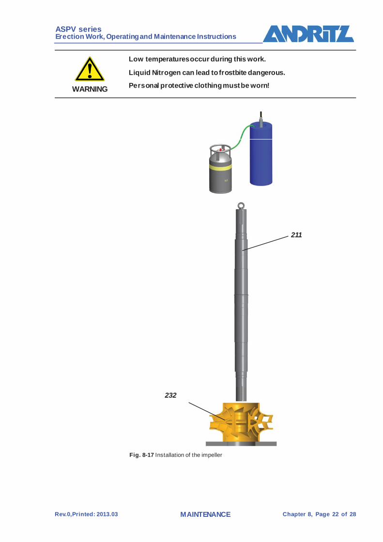
ASPV series Erection Work, Operating and Maintenance Instructions
Rev.0,Printed: 2013.03 MAINTENANCE Chapter 8, Page 22 of 28
WARNING
Low temperatures occur during this work.
Liquid Nitrogen can lead to frostbite dangerous.
Personal protective clothing must be worn!
Fig. 8-17 Installation of the impeller
211
232

ASPV series Erection Work, Operating and Maintenance Instructions
Rev.0,Printed: 2013.03 MAINTENANCE Chapter 8, Page 23 of 28
8.12.2 Impeller with key connection remove and install
Pushing off the impeller
Proceed according to the follow ing table when pushing the impeller off:
Step Activity 1 Remov e both wear rings (502) f rom the impeller.
2 Flatten the impeller locking gasket(233.2) in the impeller locking nut (233.1)
3 Remov e both the impeller locking nut (233.1) from the impeller.
4 Remov e both the impeller locking gasket (233.2) from the impeller.
6 Then pull of f the impeller (232) f orm the shaft.
Tab.8-17 Pushing the impeller off
Fig. 8-14 Pushing the impeller off
233.1 233.2 211 232
233.1 233.2 232 211

ASPV series Erection Work, Operating and Maintenance Instructions
Rev.0,Printed: 2013.03 MAINTENANCE Chapter 8, Page 24 of 28
Installation of the Impeller
Preliminary requirements:
Step Activity 1 Place the key((940.3)on the pump shaft.
7 assemble the shaf t with the impeller and adjust to the middle position of the shaft
8 assemble the impeller locking gasket and to prev ent rotation by the key slot
10 assemble the impeller locking nut and micro-adjusted to the middle position of the
impeller,and then tighten the impeller locking nut.
Tab. 8-18 Installation of the impeller

ASPV series Erection Work, Operating and Maintenance Instructions
Rev.0,Printed: 2013.03 MAINTENANCE Chapter 8, Page 25 of 28
8.12 Turning and balancing the impeller
Turning the Impeller
The impellers are manufactured in standard diameters at intervals of 5 mm.
Since the output (characteristic curve) of the pump depends on the diameter of the impeller, the characteristic curve for the appropriate impeller diameter is shown in the performance diagram.
The performance diagram also indicates the number of blades and the outlet w idth.
The turned diameter D2 is calculated from the performance characteristics, see /ASPV PUMP/TECHNICAL DATA
The turning angle alw ays measures 5.63˚.
Fig. 8-18 Turning the impeller
5.63°
ASPV series Erection Work, Operating and Maintenance Instructions
Rev.0,Printed: 2013.03 MAINTENANCE Chapter 8, Page 26 of 28
Balancing the pump shaft with impeller
All impellers must be balanced dynamically together with the shafts and shaft protection sleeves according to ISO 1904/1 G6.3.
Proceed according to the follow ing table when balancing the impeller:
Step Activity 1 Clean all contact surfaces of the pump shaft carefully with the
balancing machine. 2 Insert steel f illers in the feather key grooves and secure
adequately. Alw ays take account of the centrifugal forces arising!
3 Balance the pump shaft with impeller dynamically according to ISO 1904/1, Chapter 7.3.2.3.
Tab.8-20 Balancing the pump shaf t with impeller
CAUTION
If it is necessary to machine the impeller after it has been mounted on the pump shaft, ensure that neither the pump shaft is damaged, nor the impeller distorted.

Filename: ASPV Pump Manual EN_ASP350-680R_2013.03.doc Directory: Z:\Public_documentation\Manual and brochure (Andritz
product)\Manual\FPV-Pump\2013 for Singapore ASPV350-680R Template:
C:\Users\fshchu10\AppData\Roaming\Microsoft\Templates\Normal.dotm
Title: 2 Subject: Author: hedy Keywords: Comments: Creation Date: 2013/3/15 10:40:00 Change Number: 11 Last Saved On: 2013/3/22 16:23:00 Last Saved By: Zhuang Chugui Total Editing Time: 6,467 Minutes Last Printed On: 2013/3/22 16:30:00 As of Last Complete Printing Number of Pages: 83 Number of Words: 12,077 (approx.) Number of Characters: 68,843 (approx.)