exsteel heritage building erection manual heritage building erection manual ... erection procedure,...
TRANSCRIPT

ExSteel Heritage Building Erection ManualVersion 1.0 - June 23, 2014
ExSteel Heritage BuildingErection ManualRecommended Installation Procedures& Safety Warnings

7825 Springwater Road, Aylmer, Ontario N5H 2R4 1.800.265.7740 exsteel.com
Introduction .................................................................................................................................................... 2 Safety First ............................................................................................................................................ 2 Building Permit .................................................................................................................................... 2 Responsibility of Erection Procedures ................................................................................................ 2 Site Conditions ..................................................................................................................................... 2 Protective Equipment .......................................................................................................................... 3 General ................................................................................................................................................. 3 Approval Drawings .............................................................................................................................. 3 Erection Drawings ................................................................................................................................ 3 Drawing Package ................................................................................................................................. 4 Drawings .............................................................................................................................................. 4 General Information Page .................................................................................................................. 5 Reactions Information Pages .............................................................................................................. 6 Anchor Bolt Plan .................................................................................................................................. 8 Anchor Bolt Details .............................................................................................................................. 9 Roof Framing Plan ............................................................................................................................... 10 Frame Cross Section ............................................................................................................................. 11 Endwall Framing .................................................................................................................................. 13 Sidewall Framing ................................................................................................................................. 14 Structural Erection Details .................................................................................................................. 15 Building Preparation ........................................................................................................................... 15 Foundation/Squaring Methods .......................................................................................................... 16 Setting the Anchor Bolts ..................................................................................................................... 17 Unloading Building Components ....................................................................................................... 18 Using a Spreader Bar ........................................................................................................................... 19
Material Storage ............................................................................................................................................. 19 Shop Primer .............................................................................................................................................. 19 Storage and Protection for Sheeting .................................................................................................... 20
Erection Notes ................................................................................................................................................. 21 Recommended Tools ............................................................................................................................... 21 Parts Labels .............................................................................................................................................. 21
Primary and Secondary Steel Erection ......................................................................................................... 22 Plumbing and Squaring ................................................................................................................................. 23
Basic Sheeting Erection .................................................................................................................................. 25
Erection Sequence .......................................................................................................................................... 26
Sheeting & Trim ............................................................................................................................................. 27
Wall Panel Installation ................................................................................................................................... 28
Trim Installation .............................................................................................................................................. 28
Roof Sheeting Installation ............................................................................................................................ 29
Accessories ...................................................................................................................................................... 30
Maintenance ................................................................................................................................................... 31 Gutter Maintenance ................................................................................................................................ 31
Conclusion ...................................................................................................................................................... 31
Glossary of Terms ........................................................................................................................................... 32
Heritage Building Erection ManualIndex

7825 Springwater Road, Aylmer, Ontario N5H 2R4 1.800.265.7740 exsteel.com p 2
This erection manual is intended to provide customers and/or their erectors with the recommended procedures for erecting an ExSteel Heritage Building (Heritage Building). ExSteel Building Components (ExSteel) is not responsible for the erection of our buildings, nor do we assume any responsibility for defects that may be attributed to improper erection techniques, or negligence of other parties.
It is the customer and/or their erector’s responsibility to read this manual, and be familiar with its contents prior to erecting any new Heritage Building.
Cost effective construction depends on advanced planning done during the pre-construction stages. The project site should be examined and planned prior to material delivery. Alternate solutions to deal with unique site conditions should be developed at this time. A well planned, clean and orderly job site will usually reduce erection time and costs, create an atmosphere of safety, and offer a perception of professionalism and craftsmanship.
At ExSteel, we are committed to supplying our customers with quality products and services. This manual will improve the overall quality of our product.
Safety FirstExSteel makes every effort to incorporate safety into all of the fabricated products we supply. Making safety a first priority on the construction site must also be an important part of the overall installation plan. All work must be in accordance with the Occupational Health and Safety Act and Regulations for Construction (including latest amendments) and other local authorities having jurisdiction. All owners, supervisors and site workers must be familiar with the workplace health and safety standards in their province as well as any local code requirements. For projects in Canada, the Department of Labour has established Federal safety standards (O.S.H.A.) that all construction workers must be familiar with and practice. Failure to adhere to these standards can result in substantial fines and stop work orders.
Building PermitIt is the owner and/or contractor’s responsibility to provide to the local building department all of the necessary documentation required to obtain building permits. If building permits are not acquired prior to start of erection it could result in fines as well as stop work orders, which could cause lengthy delays in scheduling. It is also the owner/contractor’s responsibility to arrange for any permit required site inspections. ExSteel is not responsible for site inspection of any of the installed components provided.
Responsibility for Erection ProceduresWhile ExSteel has made every effort possible to outline recommended installation procedures and safety warnings, the installer/erector is solely responsible for all procedures used to install the building components provided. The CISC, Code of Standard Practice, clearly states that the fabricator (ExSteel) is not responsible for determining the erection procedure, for checking the adequacy of the connections for the uncompleted structure, or for providing erection bracing, nor shall the fabricator (ExSteel) be liable for loss, injury or damage resulting from faulty erection practices. Under no circumstances will ExSteel accept any consequential damages.
Site ConditionsThe building site must be properly prepared to allow suitable, dry storage of delivered components and safe access in and around building foundations. All delivered components must be handled in a safe manner and stored for easy access during the erection process. All safety precautions for handling light gauge material must be followed so as not to damage the product.
Heritage Building Erection ManualIntroduction

7825 Springwater Road, Aylmer, Ontario N5H 2R4 1.800.265.7740 exsteel.com p 3
Protective EquipmentAll site workers are responsible to know what Personal Protective Equipment (PPE) they need for each task during the erection process. Local Provincial regulations will dictate which PPE are mandatory on site. Below is a list of PPE that is typically required on job sites:
•HardHats •EyeandFaceProtection •HearingProtection •ProtectiveClothing •HandProtection •FootProtection •FallArrestEquipment •ReflectiveSafetyVests
Working with cold formed steel and sheet steel, if not handled correctly, may pose safety hazards to workers. It is the responsibility of those involved in erecting the building to ensure that all reasonable steps are taken to mitigate the possibility of injury. Providing and using the proper PPE is crucial in protecting against sharp edges, dropped objects, etc.
GeneralThis erection guide is used in conjunction with the building erection drawings and details supplied with the building.
Ensure that all personnel responsible for erecting this building have read the entire guide and building drawings before starting to erect this building. Note: Installers must also read and understand ExSteel’s RTL-24 installation and seamer guide for projects with standing seam roof systems.
Be sure to contact ExSteel customer service if there are any questions regarding this installation guide or building drawings/details. Understanding all of the details prior to erecting this building is important, as any incorrectly installed components can affect the overall performance of the building.
This guide describes the erection procedures for a typical Heritage Building and may not illustrate the exact building order supplied. ExSteel prepares project specific erection drawings and details for each building ordered. This guide, along with the project specific drawings will provide the details to install components, fasteners and sealants in the correct locations.
Approval DrawingsDrawings that are “ISSUED FOR INFORMATION” will be marked in the revision block on each page. These drawings are only intended for co-ordination purposes and confirming building details before construction begins. These drawings are to be reviewed carefully to ensure that all aspects of the building are correct. Once the approval drawings have been signed by the customer, the customer has confirmed that ExSteel Building Components has correctly interpreted the overall contract requirements for the building, accessories, and their location.
Drawingsthatare“ISSUEDFORINFORMATION”areincompleteanddonotreflectthefinalbuildingdetails,marknumbers, bolts, etc. Do not use approval drawings for erection purposes.
Erection DrawingsDrawings that are “ISSUED FOR ERECTION” will also be clearly marked in the revision block on each page. These drawings are to be used for setting anchor bolts, and erecting the rest of the building.
Heritage Building Erection ManualIntroduction

7825 Springwater Road, Aylmer, Ontario N5H 2R4 1.800.265.7740 exsteel.com p 4
Drawing PackageA typical construction drawing package contains the following drawings:
G1 - General Information Page R1 - Reaction Page R2 - Reaction Page S1 - Anchor Bolt Plan S2 - Anchor Bolt Details S3 - Roof Framing Plan S4 - Frame Cross Section - Rigid Frame Elevation S5 - Endwall Framing Plan S6 - Sidewall Framing Plan NOTE: Additional drawings may be required depending on building size and complexity.
DrawingsCertificate of DesignThis page contains information about the building manufacturer and erector. It also indicates the design standards, manufacturing standards and loading used to design the building. This information is required to obtain a building permit. Check this page carefully to ensure that all information is correct.
Heritage Building Erection ManualIntroduction
A660-10 Steelway Building Systems
* Initial each true statement. Mark N/A if statement does not apply.
Certificate of Design - 2010.docx Revised: May 3, 2005 Page 1 of 2
Certificate of Design and Manufacturing Conformance with
NBC, 2010 This Certificate is to affirm that all components of the steel building system described below, to be supplied by the named Manufacturer certified in accordance with CSA A660, have been or will be designed and fabricated in accordance with the following Standards to carry the loads and load combinations specified. 1. DESCRIPTION Manufacturer’s Name and Address: Steelway Building Systems, Springwater Rd., Aylmer, ON Manufacturer's Certificate No. under CSA A660:
Customer Order Number:
Building Type and Size:
(mm) Intended Use and Occupancy:
Importance Category (NBC, Sentence 4.1.2.1.(3)):
Site Location:
Applicable Building Code:
Builder's Name and Address:
Owner's Name and Address:
Engineer’s Initials *
2. DESIGN STANDARDS N/A National Building Code of Canada, 2010, Part 4: Structural Design CAN/CSA-S16-09, Limit States Design of Steel Structures CAN/CSA-S136-07, North American Specification for the Design of Cold-Formed Steel Structural Members Other (specify):
dated
3. MANUFACTURING STANDARDS N/A (a) Fabrication has been or will be in accordance with CAN/CSA-S16 and CAN/CSA-S136, as applicable. (b) Welding has been or will be performed in accordance with CSA W59 and CAN/CSA-S136, as applicable. (c) The Manufacturer has been certified in accordance with CSA W47.1, for Division 1 or Division 2, and/or CSA W55.3, if applicable. (d) Welders have been qualified in accordance with CSA-W47.1. 4. PURLIN STABILITY N/A Purlin braces are provided in accordance with CAN/CSA-S136, Clause D3 and Appendix B, Clause D3.2.2. In particular, for a standing seam roof supported on movable clips, braces providing lateral support to both top and bottom purlin flange have been or will be provided. The number of rows is determined by analysis but in no case is less than 1 for spans up to 7m inclusive or less than 2 for spans greater than 7m. 5. LOADS (a) Snow, Ice, and Rain Load N/A 1-in-50 year ground snow load, Ss,
(kPa) 1-in-50 year associated rain load, Sr,
(kPa) Wind exposure factor, Cw,
Importance factor, Is,
Roof snow load, S,
(kPa) Drift load considered (NBC Sub-section 4.1.6.2.8) refer to drawing of specific building Specified rain load (NBC, Article 4.1.6.4)
(mm). (b) Full and Partial Snow Load N/A (i) Applied on any one and any two adjacent spans of continuous purlins (ii) Applied on any one and any two adjacent spans of modular rigid frames with continuous roof beams (iii) Applied as described for the building geometry in NBC, Part 4, and in the User's Guide - NBC 2010 Structural Commentaries (Part 4), Commentary G: Snow Loads (c) Wind Load N/A 1-in-50 year reference velocity pressure
(kPa) Importance factor, Iw
A660-10 Steelway Building Systems
* Initial each true statement. Mark N/A if statement does not apply.
Certificate of Design - 2010.docx Revised: May 3, 2005 Page 2 of 2
(d) Wind Load Application N/A (i) Applied as per NBC, Part 4, Section 4.1.7 (ii) Pressure coefficients as per User’s Guide – NBC 2010 Structural Commentaries (Part 4 of Dvision B), Commentary I: Wind Loads, Figures I7 through I14 (iii) Building internal pressure Category
per User’s Guide – NBC 2010 Structural Commentaries (Part 4 of Division B), Commentary I: Wind Loads (e) Crane Loads (where applicable) N/A Type:
(top running)(under-running)(jib) Capacity:
(tonnes) Wheel base:
(m) Maximum static, vertical wheel load:
(kN) Vertical impact factor:
% Lateral factor:
% Lateral wheel load:
(kN) Longitudinal factor:
% Maximum longitudinal load:
(kN/side) (f) Mezzanine Live Load:
(kPa) N/A (g) Seismic Load: N/A (Applied as per NBC, Part 4, Sub-section 4.1.8 Sa(0.2)
, Sa (0.5)
, Sa (1.0)
, Sa (2.0)
, Fa
, Fv
, IE
(h) Other Live Loads N/A (Specify):
(i) Dead Loads N/A Dead load of building components is incorporated in the design Collateral load (mechanical, electrical, ceiling, sprinklers, etc.):
(kPa) Mezzanine:
(kPa) Other (specify):
(
) (j) Load Combinations N/A Applied in accordance with NBC, Part 4, Section 4.1. 6. GENERAL REVIEW DURING CONSTRUCTION The Manufacturer does not provide general review during construction for regulatory purposes. 7. CERTIFICATION BY ENGINEER I
, a Professional Engineer registered or licensed to practice in the Province or Territory of
, hereby certify that I have reviewed the design and manufacturing process for the steel building system described. I certify that the foregoing statements, initialed by me, are true.
Signature:
Name:
Title:
Affiliation:
Date:
Professional Seal
SD1 - Structural Erection DetailsSD2 - Structural Erection Details C1 - Roof Cladding PlanC1 - Roof Cladding PlanC2 - Endwall Cladding ElevationC3 - Sidewall Cladding ElevationCD 1 - Cladding Erection DetailsCD 2 - Cladding Erection Details

7825 Springwater Road, Aylmer, Ontario N5H 2R4 1.800.265.7740 exsteel.com p 5
General Information PageThe General Information page contains a variety of information. Erectors should familiarize themselves with the information on this page before beginning the erection of any ExSteel Building.
Heritage Building Erection ManualIntroduction
519 - 765 - 2244
7825 Springwater RoadAylmer, Ontario N5H 2R4
www.exsteel.com
1
3
2
1) General Notes - This section contains information about General Erection Instructions, Bracing Reactions, Responsibility, Shop Primer, Field Work, and Material Specifications.
2) Drawing Schedule - The drawing schedule gives a list of the drawing numbers and titles included in the drawing package.
3) Revision Box - Inside the revision box will be a revision number, a description, along with the date and the engineer/checker’s initials. When drawings are revised a new revision line will be added to the revision box. When erecting a building ensure that the revision description reads “ISSUED FOR ERECTION”.

7825 Springwater Road, Aylmer, Ontario N5H 2R4 1.800.265.7740 exsteel.com p 6
Reactions Information PagesThese pages show the rigid frame and endwall reactions, anchor bolts and base plates, as well as bracing reactions and general notes.
Heritage Building Erection ManualIntroduction
519 - 765 - 2244
7825 Springwater RoadAylmer, Ontario N5H 2R4
www.exsteel.com
1
2
1) Rigid Frame Maximum Reactions, Anchor Bolts and Base Plates - These tables show the maximum factored reactions for the governing design load combinations, and the quantities and size of the base plates and anchor bolts. Each frame type has a separate table. Frames of the same type will be identified at the bottom.
2) Rigid Frame Basic Column Reactions - This table shows the unfactored reactions for all the loading conditions for which the building has been designed. Similar frames are grouped together and are indicated at the bottom of the table.

7825 Springwater Road, Aylmer, Ontario N5H 2R4 1.800.265.7740 exsteel.com p 7
Heritage Building Erection ManualIntroduction
519 - 765 - 2244
7825 Springwater RoadAylmer, Ontario N5H 2R4
www.exsteel.com
3
5
4
6
3) EndWall Column Basic Column Reactions - This table shows the unfactored reactions at the endwall column base plate and the quantities and size of the base plates and associated anchor bolts.
4) Building Bracing Reaction - This table indicates the location and unfactored reactions of any wall bracing.
5) Notes for Reactions - This is a list of the design criteria and loading used to design the building. Depending on the building, it may also contain any snow drift diagrams.
6) General Notes - This is a list of general information that pertains to the reactions indicated on this page.

7825 Springwater Road, Aylmer, Ontario N5H 2R4 1.800.265.7740 exsteel.com p 8
Heritage Building Erection ManualIntroduction
519 - 765 - 2244
7825 Springwater RoadAylmer, Ontario N5H 2R4
www.exsteel.com
3 3
4
4
1
1 2
1) “Out-to-Out of Steel” - These dimensions are the overall length and width of the building, measured from the outside face of the girt to the outside face of the girt, known as the steel line. These dimensions are usually the out to out concrete dimension. If the edge of the concrete will not be at the steel line, take extra care when locating the anchor bolts.
2) “Hold this Dimension” - This is a critical dimension between the column anchor bolt sets for a rigid frame. If anchor bolts are not spaced accurately the rigid frame columns will be out of plumb and prevent the frame connections from connecting properly.
3) Endwall Column Offsets - These dimensions are taken from outside of steel to the web of framing. Refer to the appropriate anchor bolt detail for the location and offsets of the anchor bolts.
4) Bay Spacing - These dimensions are the distance between the center-line of column to the center-line of column. If these dimensions are not maintained, the secondary framing will not fit the building properly.
Anchor Bolt PlanThis is the overall plan of the foundation, showing building length and width, endwall column offsets, anchor bolt placement, column orientations, as well as the underside of base plate elevations (unless noted in individual base details)andfinishedfloorelevation.

7825 Springwater Road, Aylmer, Ontario N5H 2R4 1.800.265.7740 exsteel.com p 9
NOTE: The various Anchor Bolt Details may reoccur at several locations around the building. The orientation of the Anchor Bolt Details may not match the overall plan at all locations. The details may be rotated or mirrored from the orientations on the overall plan. When setting anchor bolts, orient the group as per the overall plan, using the details for the size, spacing, and offsets of the anchor bolts.
Anchor Bolt DetailsThese are the individual anchor bolt details indicated on the anchor bolt plan.
Heritage Building Erection ManualIntroduction
519 - 765 - 2244
7825 Springwater RoadAylmer, Ontario N5H 2R4
www.exsteel.com
1) Anchor Bolt Details - The anchor bolt details show the anchor bolt diameter and the overall length and width of the base plate. Anchor bolt placement is shown from the outside of steel line either from the endwall (EW) and/or sidewall (SW). Any variation in anchor bolt size, quantity, placement, or underside of the base plate elevation will be shown on a separate detail.
1

7825 Springwater Road, Aylmer, Ontario N5H 2R4 1.800.265.7740 exsteel.com p 10
Roof Framing PlanThe roof framing plan shows the roof framing components along with sizes and their locations.
Heritage Building Erection ManualIntroduction
519 - 765 - 2244
7825 Springwater RoadAylmer, Ontario N5H 2R4
www.exsteel.com
1) Roof Dimensions - These dimensions are the overall length and width of the roof, measured from the outside face of the girt to the outside face of the girt at the eave and gable face. These dimensions will typically match the anchor bolt plan. If the building has eave extensions and/or gable overhangs an extra dimension will be added after the main building dimensions.
2) Bay Spacing - These dimensions indicate the distance between the centre line of the column to the centre line of the next column.
3) Roof Framing - All of the roof framing members are shown on the roof framing plan. This includes purlins, purlin stabilizers, eave purlins, bracing, bearing clips, ridge plates and gable angles. Purlins that are repetitive are labeled only once per roof surface and are indicated as typical (Typ) after their part number on the erection drawings.
4) Roof Plan Member Table - The roof plan member table lists the mark number and part ID for all roof framing members.
5) Purlin Laps - These dimensions indicate the length of the purlin laps. Purlin lap dimensions are taken from the gridline to the end of the purlin. Purlin laps are the same on both sides of the rafter but can change from gridline to gridline. Ensure that the proper lap is at the correct location.
3
5
4
1
2
1

7825 Springwater Road, Aylmer, Ontario N5H 2R4 1.800.265.7740 exsteel.com p 11
Frame Cross SectionThe rigid frame cross section shows the rigid frame elevation, purlin spacing and gridlines the rigid frames are located on.
Heritage Building Erection ManualIntroduction
519 - 765 - 2244
7825 Springwater RoadAylmer, Ontario N5H 2R4
www.exsteel.com
1) Rigid Frame Cross Section - This is a drawing of the assembled rigid frame. The drawing shows what gridlines the frames are on, the layout of parts that make up the rigid frame, bolt connections, and finished dimensions of the building. If a building has multiple frames there will be additional drawings. Ensure that each frame is at the appropriate gridline.
2) Building Dimensions & Clearances - The building dimensions show the overall width and height of the building. These dimensions are from the outside of girts and purlins. The height and width clearances inside the frame are also shown on the drawing.
3) Girt Spacing - The location and orientation of girts are shown. The dimensions are to the web of the girt. Refer to the Endwall Framing (page 13) and Sidewall Framing (page 14) for mark number and girt sizes.
4) Purlin Spacing - The locations and orientation of the purlins are shown. The dimensions of the purlins are shown from the top of the eave to the web of the purlin, and then from purlin web to purlin web. Refer to the Roof Framing Plan (page 10) for mark numbers and purlin sizes.
3
5
4
2
2
1
6
6
7
7
7825 Springwater Road, Aylmer, Ontario N5H 2R4 1.800.265.7740 exsteel.com p 12
5) Flange Brace Locations - Flange braces (FB) are shown on the roof and walls of the building at FB locations. Flange braces can be single sided indicated with a (1) or double sided (2). Flange brace marks are based on the size and length of the brace. Refer to the top left corner of the page for Flange brace thicknesses related to their marks, see #7.
6) Rigid Frame Member Table - This lists the mark number and part ID for all rigid frame members.
7) Rigid Frame Connections - The rigid frame splice plates are indicated on the drawing as CL-1, CL-2, etc. The splice plate numbers coincide with the Splice Plate & Bolts table in the top left corner of the page. The table shows the splice mark, bolts and plate size. The quantity, type, diameter, and length of bolts are also shown for each splice plate connection. Ensure that the proper bolts are used as indicated.
Heritage Building Erection ManualIntroduction

7825 Springwater Road, Aylmer, Ontario N5H 2R4 1.800.265.7740 exsteel.com p 13
Endwall FramingThe Endwall Framing drawing shows the various building members for the endwalls, as well as the opening locations and sizes. The endwalls are identified by grid line number and as Left Endwall, Right Endwall. Framing elevations are oriented looking at the building from the outside.
Heritage Building Erection ManualIntroduction
519 - 765 - 2244
7825 Springwater RoadAylmer, Ontario N5H 2R4
www.exsteel.com
35
4
4
2
1
1
6
1) Building Dimensions - The overall dimensions of the wall are measured from the outside face of the girt to the outside face of the girt. These dimensions will match the out to out steel dimensions on the Anchor Bolt Plan (page 7/8).
2) Bay Spacing - These dimensions indicate the distance between outside of steel to web of framing.
3) Girt Spacing - The location and orientation of girts are shown. The dimensions are to the web of the girt.
4) Framing Members - All wall framing members are shown and a mark number is given. These mark numbers coincide with the Member table on the top right of the page.
5) Factory Located Openings - All overhead doors are factory located. The dimensions to locate openings will be either from the outside of the girt to the edge of the opening, or from the web of framing to the edge of the opening. The width and height of the opening are also shown on the drawing.
6) Bolt Table - This table indicates the size, type and length of bolts to be used for the column and rafter connections. The location of the bolts is indicated by the part numbers of the connecting members. Ensure that the proper bolts are used as indicated.

7825 Springwater Road, Aylmer, Ontario N5H 2R4 1.800.265.7740 exsteel.com p 14
Sidewall FramingThe sidewall framing drawing shows the various building members for the sidewalls, as well as the opening locations and sizes. The sidewalls are identified by grid line number. Framing elevations are oriented looking at the building from the outside.
1) Building Dimensions - The overall dimensions of the wall are measured from the outside face of the girt to the outside face of the girt. These dimensions will match the out to out steel dimensions on the Anchor Bolt Plan.
2) Bay Spacing - These dimensions indicate the distance between the center line of a column and the center line of a column.
3) Girt Spacing - The location and orientation of girts are shown. The dimensions are to the web of the girt.
4) Framing Members - All wall framing members are shown and a mark number is given. These mark numbers coincide with the Member table on the top right of the page.
Heritage Building Erection ManualIntroduction
519 - 765 - 2244
7825 Springwater RoadAylmer, Ontario N5H 2R4
www.exsteel.com
3
4
2
1
1

7825 Springwater Road, Aylmer, Ontario N5H 2R4 1.800.265.7740 exsteel.com p 15
Structural Erection DetailsThis page shows the general connections and clips used for erecting the building.
Heritage Building Erection ManualIntroduction
519 - 765 - 2244
7825 Springwater RoadAylmer, Ontario N5H 2R4
www.exsteel.com
Building PreparationExSteel provides general information for the foundation and concrete slab. However, ExSteel is not responsible for the design or installation of the foundation. All soil preparation and foundation design must be prepared by a licensed engineer qualified for this work.
The foundation and concrete slab should be checked prior to material being delivered for correct out-to-out dimensions, Anchor bolt location, and perimeter notching details. These dimensions and details are shown on the anchor bolt and anchor bolt detail drawings.
If the foundation wall or slab is too wide or too narrow, stud columns may not be adequately supported and remedial work of the concrete slab must be completed before proceeding with building erection.
Theslabfloorlevelshouldbecheckedbyplacinga10footstraightedgeonthesurfaceatrandomlocations.Thesurfacelevelshouldnotvarybymorethan1/8”.Excessivedipsinthefloorslabatstudcolumnlocationswillaffectcolumn plumbness. Proper concrete fillers should be used to correct this problem.
Alwayschecktheoverallqualityofthefloorslabforsignsofgouges,trowelmarksandchippingalongtheedges.The perimeter of the concrete should be trowel finished and of uniform width and depth.
Repair any slab defects prior to erecting steel components. Always allow for proper curing time before proceeding.

7825 Springwater Road, Aylmer, Ontario N5H 2R4 1.800.265.7740 exsteel.com p 16
The concrete should be allowed to cure for 14 days prior to erecting the building. Damage to the concrete can occur if work is started prior to the 14 day cure time.
Foundations/Squaring MethodsCheck that the slab is square using a transit if available or by the “right triangle method” (see Figure 1). Start at one corner and mark 6’-0” along the sidewall slab edge. Go back to corner and mark 8’-0” along the endwall edge. The distance between the two marked points should be 10’-0”. Also check the overall corner to corner dimensions as shown in figure 2.
Diagonal Method
1) Adjust the foundation layout lines until dimensions A & B are equal in length. 2) Check again for building length and width per building drawings.
Transit Method:
1) Locate transit exactly over the corner intersection point of string line. 2) Sight along one building line. Swing transit though 90° to establish adjacent building line. 3) For accurate results, the transit must be exactly level and in perfect working condition.
Heritage Building Erection ManualIntroduction

7825 Springwater Road, Aylmer, Ontario N5H 2R4 1.800.265.7740 exsteel.com p 17
Setting the Anchor BoltsLayout the building gridlines on the concrete slab as shown on drawing S1.
THE ACCURATE LAYOUT OF THE GRIDLINES IS CRITICAL.
Mark out all anchor bolt locations onto the slab using the dimensions from the Anchor Bolt Plan. Double check all dimensions and drill and anchor the bolts into the slab.
Heritage Building Erection ManualIntroduction

7825 Springwater Road, Aylmer, Ontario N5H 2R4 1.800.265.7740 exsteel.com p 18
Unloading Building ComponentsShipment Inspection
Be sure to check all of the delivered materials to ensure you have received the components listed on the shipping lists. Any shortages must be reported to ExSteel customer service within 24 hours. Critical components such as bracing straps must be accounted for before building erection can begin.
Note any damaged components on the shipper’s bill of lading before the truck(s) leave the site. Any damaged components must be reported to ExSteel customer service within 24 hours.
If damage is concealed until crating or packaging is removed, call your agent at once for an inspection and obtain an inspection memorandum covering concealed damage.
Safety Precautions
Before unloading your shipped components, be sure to check that there is adequate room on site for all of the material delivered.
Always inspect for overhead hydro wires to ensure you are unloading in a safe area away from overhead wires and other obstructions.
If access to the site is limited or located on a busy street, arrange in advance with local traffic authorities for any special requirements or traffic control personnel necessary for truck access.
Ensure that there is an adequate number of personnel and material handling equipment available to safely unload the truck. Care must be taken to lift all bundles correctly so as to not damage the material. Check each bundle and calculate the total weight based on the individual component weights listed on the shipping lists. Large cladding bundles will need a correctly sized forklift or hoisting equipment. Spreader bars may be required to evenly distribute lifted loads on longer cladding bundles. Panel bundles 25’ or longer will require two forklift trucks.
Stay well in the clear of loads being lifted by machinery and keep hands and feet clear of moving loads.
Heritage Building Erection ManualIntroduction
7825 Springwater Road, Aylmer, Ontario N5H 2R4 1.800.265.7740 exsteel.com p 19
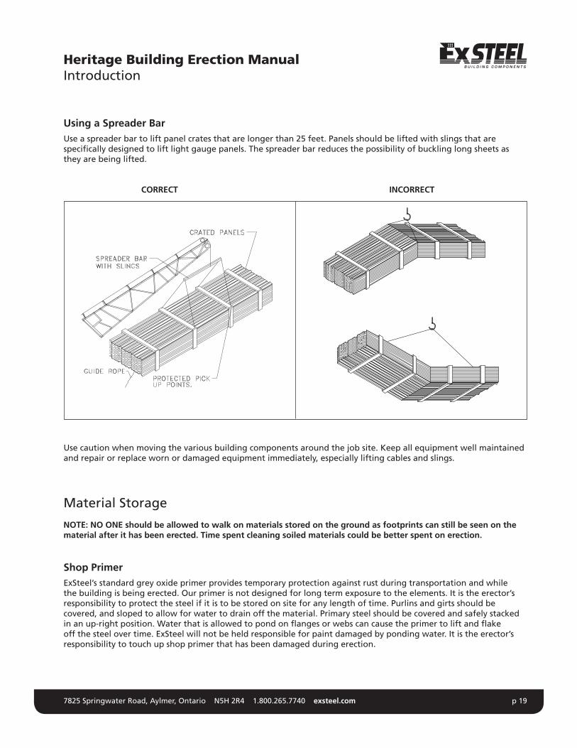
Using a Spreader BarUse a spreader bar to lift panel crates that are longer than 25 feet. Panels should be lifted with slings that are specifically designed to lift light gauge panels. The spreader bar reduces the possibility of buckling long sheets as they are being lifted.
CORRECT INCORRECT
Use caution when moving the various building components around the job site. Keep all equipment well maintained and repair or replace worn or damaged equipment immediately, especially lifting cables and slings.
Material Storage
NOTE: NO ONE should be allowed to walk on materials stored on the ground as footprints can still be seen on the material after it has been erected. Time spent cleaning soiled materials could be better spent on erection.
Shop PrimerExSteel’s standard grey oxide primer provides temporary protection against rust during transportation and while the building is being erected. Our primer is not designed for long term exposure to the elements. It is the erector’s responsibility to protect the steel if it is to be stored on site for any length of time. Purlins and girts should be covered, and sloped to allow for water to drain off the material. Primary steel should be covered and safely stacked inanup-rightposition.Waterthatisallowedtopondonflangesorwebscancausetheprimertoliftandflakeoff the steel over time. ExSteel will not be held responsible for paint damaged by ponding water. It is the erector’s responsibility to touch up shop primer that has been damaged during erection.
Heritage Building Erection ManualIntroduction

7825 Springwater Road, Aylmer, Ontario N5H 2R4 1.800.265.7740 exsteel.com p 20
Storage and Protection for SheetingIf moisture is present on any delivered components it should be wiped dry immediately. Short-term job site storage of building materials may be tolerated provided these materials are kept dry.
If installation of the building will be delayed by more than 72 hours, the most desirable storage place is under-roof in a cool, dry, well ventilated area. When storing outdoors is unavoidable, the following is recommended:
Materials should be placed at an angle sufficient to allow proper drainage. Always allow several inches of clearance between the lower end of the material and the ground. Long material should be supported in the center to prevent water ponding.
Adequate blocking should be placed between panels to allow air movement between sheets and avoid condensation. If condensation occurs, it must be wiped dry immediately and measures taken to avoid this condition.
Store materials out of direct sunlight (if possible), away from chemically aggressive substances (e.g. salt, cement, fertilizer), away from material that could contaminate the surface (e.g. diesel oil, paint, grease) and away from site traffic.
Protective tarps should be placed to allow proper ventilation but do not allow entry of wind-driven rain. Never cover materials with plastic sheets or wrappings. Plastic will trap moisture and lead to rusting.
Heritage Building Erection ManualMaterial Storage

7825 Springwater Road, Aylmer, Ontario N5H 2R4 1.800.265.7740 exsteel.com p 21
Heritage Building Erection ManualErection Notes
Recommended ToolsTo ensure efficient and quality erection of the ExSteel Heritage Building, the following tools are recommended:
•Personalprotectiveequipment(PPE)includinggloves,hardhats,safetyboots, hearing protection and safety goggles •Safetyharness&fallarrest •Firstaidequipment •Portablefireextinguisher •Crane,forkliftorboomtruckssuitableformaterialhandling •Spreaderbars,slings •Temporaryerectionbracing •Battery,electricorpneumaticscrewguns(75–125ft-lbstorque) •Hammerdrillwithappropriatebitsforanchors •Powercords •Generator •Ladders •Leveland/ortransit •Selflockingweldersclamps •Compoundtinsnips •Electricnibbler •Utilityknife •Tapemeasures(25’and100’)andsquares •10’straightedge •Caulkinggun •Rubberheadmallets •Chalkline,20feet.
Part LabelsAll building components have been marked with a part number to make them easily identifiable from one another. Some parts are identical in shape and only vary in length or in hole location. It is important that the correct part is used in the location specified on the erection drawings.
Part Class
Length
73597
C-100WESTEST4’10 1/2” 08C13 1 of 2
ISO 9001 RegisteredMade in Canada
CSA A66026/05/2014
Job Number
Part Number
Quantity
Part Name

7825 Springwater Road, Aylmer, Ontario N5H 2R4 1.800.265.7740 exsteel.com p 22
1) Assemble frames on the concrete slab. Do not fully tighten bolts. Measure width of frame at the base and top of column. Ensure that the measurement matches the width indicated on the drawings. Square frame by measuring from base plate to opposite eave; adjust as needed. Assemble all of the purlin and girt clips to the frames at this time. Finger tighten all bolts. Stack frames up to 3 frames.
2) Raise the first frame starting at a braced bay (pictured above). Hold in place until the frame is secured and temporary bracing has been installed.
IMPORTANT: Both temporary and permanent bracing are critical, both
for safety and to prevent excessive twisting & damage of the steel during erection.
The rafters will impose large loads on the columns. Ensure that the girts, flange braces, and sidewall bracing have been installed before the rafters are lifted into place.
Heritage Building Erection ManualPrimary and Secondary Steel Erection
WIDTH
WIDTH
EQ
EQ
LIFT AT TWO POINTS MINIMUM.

7825 Springwater Road, Aylmer, Ontario N5H 2R4 1.800.265.7740 exsteel.com p 23
3) Erect adjacent braced frame, girts, purlins, and cross bracing.
Plumbing and SquaringThe braced bay should be accurately plumbed and squared after erection of all purlins and girts to insure correct alignment of the succeeding bays. This is achieved buy adjusting the roof and wall bracing using the fallowing procedure.
Heritage Building Erection ManualPrimary and Secondary Steel Erection
a) Install the bracing loosely. Fasten a plank to the top of the frame and hang a plumbob off the outside edge. Adjust the bracing frame by loosening or tightening the nuts on the bracing (remember that when you tighten one rod you need to loosen the other.) the column is plumb when dimension “B”
is the same as dimension “A”.
A
B
MAIN FRAMECOLUMN
CENTER LINEOF COLUMN
B

7825 Springwater Road, Aylmer, Ontario N5H 2R4 1.800.265.7740 exsteel.com p 24
b) Align the roof beams in progression from the eave to the ridge. Plumb the rafter at each connection point by tightening or losing the bracing at those connections. String a line between the center of the column frame line. Drop a plumbob from the ridge. Adjust the bracing as necessary so the plumbob is in line with the line at the base of the frame.
a. Measure from the plumbob to the edge of the building and ensure that the ridge is centered in the building.
NOTE: Plumbing and squaring is one of the most important parts of erecting a building, be sure that the braced bay is level and plumb and square to avoid any problems when continuing the building erection.
4) Erect the remaining frames and install purlins and girts.
5) Finally, erect the end walls and attach eave plates. Install all roof and wall stabilizers and base angle.
Heritage Building Erection ManualPrimary and Secondary Steel Erection
A
B
RIDGE POINT
ROOF RAFTER
DETAIL - A
RIDGE POINT

7825 Springwater Road, Aylmer, Ontario N5H 2R4 1.800.265.7740 exsteel.com p 25
Heritage Building Erection ManualBasic Sheeting Erection
Recommended ToolsTo ensure efficient and quality sheeting erection, the following tools are recommended:
•2000-2500rpmscrewgunwithtorqueadjustableclutch •manualorelectricrivettool •6-7amporhigherratedtools
DO NOT USE IMPACT TOOLS
To assure proper voltage to the tool, extension cords should be checked for proper wire size/chord length.
•16gaugewire,maximumchordlength=100’ •14gaugewire,maximumchordlength=200’ •12gaugewire,maximumchordlength=300’
Driving TipsDrive fasteners perpendicular to the panel surface.
Compress the insulation at fastener locations with one hand while driving the fastener with the other. This will help keepthepanelflatandthepreventthefastenerfrom“walking”.
Excessive pressure can cause drill point failure. Let the fastener do the work.
Field Cutting of PanelsWhen field cutting or mitering roof/wall panels, non abrasive cutting tools such as nibblers or tin-snips shall be used. Abrasive cutting tools such as mechanical grinders or power saws, can damage the galvalume finish and create excess metal shavings that can corrode the panels. The use of non-approved cutting devices may void the factory warranty. Whenever possible, fit the material so that the factory cut edge is exposed and the field cut edge is covered.
Wall Panel Erection Notes •Block girts to “level” position before starting panel erection. Keep this blocking (blocking is not provided by
ExSteel) in place until the wall panel to girt fasteners are installed. •Makesurethatthefirstwallpanelisaligned and plumb. •Toprevent“Oil-Canning”,all panel fasteners should start from the base and then be fastened to each girt
location working toward the eave. •Makesurethatthefoundationissquare, level and correct to the out-to-out steel line dimensions. •Prevailingwind,maintrafficarea,etc.shouldbetakenintoconsiderationwhensheetingthewall. •Panels must be stored properly to prevent moisture damage.
CORRECT
Sealing material is slightly visible around the metal washer.
Sealing material is not visiblearound the metal washer.
Sealing material is deformed beyond the edge of the metal washer.
TOO LOOSE TOO TIGHT

7825 Springwater Road, Aylmer, Ontario N5H 2R4 1.800.265.7740 exsteel.com p 26
Be sure that all lateral braces, purlin stabilizers and sag rods are in place before sheeting the building. Double check that the building is square before sheeting the building. It is strongly recommended that the wall cladding be installed first. The wall cladding adds rigidity to an incomplete structure.
Install sidewall sheets first, beginning on the side away from the primary visual source, such as the rear wall of the building. This is will give you the best appearance. The roof sheets are installed last. Start the roof sheets so that the laps are away from the prevailing wind.
Heritage Building Erection ManualErection Sequence

7825 Springwater Road, Aylmer, Ontario N5H 2R4 1.800.265.7740 exsteel.com p 27
The owner’s acceptance of any building depends on its finished appearance. Sheeting, trim and accessories are the most conspicuous elements of construction and must be installed with the greatest of care.
It is recommended that the wall sheeting be installed first as wall panels lend a high degree of rigidity to an incomplete structure.
Before sheeting is installed:
1) Installbaseflashingandgableangle.Noteplacementofmaterialsandfastenersused.Thesecanbefoundonthe cladding erection detail drawings.
2) It is important to a building’s appearance that straight screw patterns be maintained for the full length of a
wall surface. This can be obtained by pre-drilling the wall panels. a) First measure the girt spacing from base to centre of exposed face of girt. Before drilling an entire stack
of panels drill one test sheet to make sure that the holes line up properly. b) Stack sufficient panels in a pile for a single bay and drill the stack of panels in one operation. Pre-drilling
does more than assure correct alignment, it saves time in fastening as only the girt material must be penetrated. The hole in the panel acts as a pilot for the fastener as it starts to drill.
Heritage Building Erection ManualSheeting & Trim

7825 Springwater Road, Aylmer, Ontario N5H 2R4 1.800.265.7740 exsteel.com p 28
Installation of the wall panels should begin at the end of the building farthest from the point of maximum site exposure, progressing toward the prevailing view. Thus, the shadow of the panel lap joint will not be apparent when the wall is viewed from this perspective. Blanket insulation and wall sheeting should be installed simultaneously, with the vapour barrier facing of the insulation toward the warm side of the building.
Precise vertical alignment of each wall panel must be maintained prior to the final fastening. Misalignment of one panel will cause progressive problems throughout the remainder of the sheeted surface. When erecting the wall panels, mark the panel width modules at the top and bottom of each panel fastening base. This helps maintain panel dimensions as they are being installed. Longer panels may have to be marked in the middle as well.
CAUTION: DO NOT HANDLE PANELS BY LAP EDGE AS THIS MAY CAUSE DIMPLES
•endwallpanelsmayhavetobefieldcutifbacklappedtofitproperly •panelfastenersmustbeinstalledinstrictaccordancewiththeprojectdrawings
As the wall fasteners penetrate the girts (even when the panels are pre-drilled) small steel shavings are often scattered onto the panel surface. These particles are magnetized and adhere to the wall surface. If they are not removed, they will cause rust spots on the panel finish which are difficult and time consuming to remove. Wiping the wall panel with a clean cloth at the time the fastener is driven will prevent this problem. Also, make sure that thefilingsthathavecollectedonthebaseflashingaresweptoffattheendofeachday.Thisgoeswithfilingsfromcutting wall panels.
Trim Installation
The trim (installed simultaneously or right after the wall panels) has an enormous impact on the appearance of a building. Trims can easily be damaged by mishandling. If the trim is not true it distracts from, rather than enhances, thefinalappearanceofthebuilding.Trims,flashingsandclosuresarefastenedandsealed,asindicatedbyprojectdrawings. Once again, pre-assemble as many trims as possible on the ground.
Heritage Building Erection ManualWall Panel Installation

7825 Springwater Road, Aylmer, Ontario N5H 2R4 1.800.265.7740 exsteel.com p 29
Sheeting the roof is the single most important part in the erection of a structure. The roof must protect the building interior for many years.
As with the walls, roof sheets and insulation are installed simultaneously. All sheets should be positioned as indicated by the project drawings. Manufacturer’s erection drawings for eave, gable and ridge detailing should be followed closely. It is imperative that the roof panel extend past the eave trim by 2” or more. If the panel does not extend 2 or more inches past the eave trim winter roof water will run down the trim and the wall forming large icicles. The ice is unsightly and may damage the building. See erection drawings for eave details.
Care must be taken with the alignment of opposite sloped panel ribs for integrity of the ridge condition. If possible, lay out the roof panels so that the lap joint is on the leeward side of the most severe weather direction. This will reduce the possibility of a wind driven rain leak.
The customer is supplied with three materials to prevent roof leaks. They are tape sealant, tube caulking and closure strips. The proper application of each is very important. Follow the manufacturer’s recommendation for sealer, closure and fastener placement. Sealants should be installed during the erection of the lap sheet (i.e. on Storm Seal roofs or liners). If the tape is installed too far in advance it can dry out or collect dirt, both of which could interfere with the sealing of the metal sheets. To ensure a tight seal, wipe the sheets with a rag to remove any oil, dirt or moisture.
CAUTION: NEVER USE AN UNFASTENED PANEL AS A WORK PLATFORM
Heritage Building Erection ManualRoof Sheeting Installation

7825 Springwater Road, Aylmer, Ontario N5H 2R4 1.800.265.7740 exsteel.com p 30
A tape sealant should not be stretched during application. Remember to remove the release paper just prior to lapping the sheets. The end result of an incorrect installation will be a faulty lap seal and a costly leak.
Tube caulking should be used per drawing specifications and as necessary in accordance with sound erection practice.
Exerciseextremecautionwhenwalkingoninstalledroofpanels.Rooftrafficmustbeconfinedtopanelflatspreferably at the purlin line. Never walk or stand on the major panels ribs. This not only illustrates poor erection practice but it also opens up the lap joint and destroys the weather tightness of the roof. Never apply a concentrated single force to any major corrugation for any reason. Use walk boards to distribute loads over two or more corrugations.
It is imperative that drill filings be swept from the roof at the end of each work day. Drill shavings, either from saw cuts or drilling and fastening operations, may become embedded in the roof coating and within a matter of hours rust can develop. This rust could eventually run off of the roof and stain the wall finish as well.
There are many choices available to building owners in both roof systems and fastening devices. Each has its own merit and impact upon appearance, insurance requirements, life cycle, value and cost. Most utilize sheet metal fasteners in various locations and capacities. Proper installations of these fasteners can only be accomplished with the proper equipment.
Accessories
Accessories are chosen for their function and appearance. Most become integrated into the general building appearance. For this reason, they must be installed with the same care and attention as the sheeting and trim.
Accessory items typical to many structures include: framed openings, personal or service doors, skylights and wall lights, interior treatments, ventilation devices, overhangs and facia systems. Recheck the erection drawings for the location of each accessory and be sure to follow the manufacturer’s instructions explicitly for installation.
InspectionA thorough inspection of the entire facility should be made by the owner prior to the owner’s final acceptance tour. All necessary corrections and adjustments should be made at this time. Things to look for should include: • theintegrityofthestructuralandsheetmetalconnections •missingcomponents •damagedcomponents •accessoriesoperatingproperly •marredfinishes
Finally, the job site should be left in a condition that would satisfy you if you were the owner. A littered site detracts from the appearance of a newly completed building. No job site should be considered complete until all construction debris is removed.
Heritage Building Erection ManualRoof Sheeting Installation
7825 Springwater Road, Aylmer, Ontario N5H 2R4 1.800.265.7740 exsteel.com p 31
Gutter MaintenanceGutters must be kept free of ice accumulation and fallen debris. Gutters cannot take the load of heavy ice and snow build-up. In order to ensure proper function of gutters to divert water off the roof they should be maintained and checked on a regular basis.
Caution must be taken during the erection process if winds are predicted. The wind loading on the exposed interior partition walls can be larger than on the completed structure. Damage or collapse can occur on improperly braced wall sections during installation. Always be aware of weather conditions and ensure adequate temporary bracing is used. Always brace erected walls prior to leaving the work site each day.
Conclusion
A clean, well organized job site promotes safe work habits among construction workers. Safety cannot be stressed enough. Workmen should be trained to use the proper safety equipment and procedures. Proper safety gear for the specific job should be enforced at all times. Safety cannot be solicited through a booklet, a rule or a program. It is embodied in awareness, responsibility, commitment, training and supervision.
“Safety is the best insurance for keeping everyone in business.”
ExSteel Building Systems hopes that these tips will help your erection jobs move more smoothly and result in the best constructed buildings possible. These buildings will be a credit to the industry and continue the evolution that has made metal buildings a major force in construction today.
Heritage Building Erection ManualMaintenance

7825 Springwater Road, Aylmer, Ontario N5H 2R4 1.800.265.7740 exsteel.com p 32
Accessory A supplementary building product such as a door, window, ventilator, skylight, etc.
Anchor Bolts Bolts utilized to secure building components to the foundation. In the case of primary framing, these bolts are embedded in the foundation and secured to the column baseplate.
Anchor Bolt Plan A plan of the foundation showing all dimensions and sections required to properly locate and set all anchor bolts, including projection above concrete, recesses, etc.
Bay The distance between the centerline of the first interior frame and the outside of the endwall structure.
Bearing Clip The clip angle used to bolt secondary members to the main frames.
Bill of Material A list of components used for fabrication, shipping, receiving and accounting purposes.
Brace Bay A roof or wall bay that is cross braced with cable or rod.
Brace Rods Rods used on roof and sidewalls of some buildings to transfer wind, seismic, and lateral crane forces to the foundation.
“C” Section A member cold formed from steel coil in the shape of a “C”, used primarily in bearing frame endwalls and framed openings.
Cable Brace Cables used as the primary bracing method for the roof and sidewalls. These cables transfer wind and seismic forces to the foundation.
Clip Angle An angle used for fastening various members together.
Cold Formed Section A structural shape that is formed by bending thin gauge (typically 10-16 gauge.) material at ambient temperature. This is typically done on a roll former.
Column A primary structural member used in a vertical position to transfer loads from roof beams, trusses or rafters to the foundation.
Eave The line along the top of the sidewall, formed by the intersection of roof and wall panels.
Eave Purlin The roof framing member spanning between main frames at the eave of the building.
Endwall A term used to describe the entire composition of a building end.
Erection Drawings Drawings showing the roof framing plan, wall framing plan, endwall framing, cross section and other parts of the building.
Flange The projecting edge of a structural member.
Gable The triangular portion of the endwall of a building, directly under the sloping roof and above the eave line.
Gable Angle An angle that caps off the gable end of the building to allow for panels to be screwed.
Girt Cold formed secondary horizontal structural used as wall system supports.
Header A horizontal structural member over a door opening, window or other framed opening.
Out-to-out Overall dimensions.
Plumbob A weight used at the end of a plumb line, used to check vertical perpendicularity or depth.
Ponding The gathering of water at low or irregular areas on a roof, or primary or secondary members.
Purlin Cold formed secondary structural used as roof system supports.
Purlin Stabilizer The secondary framing member attached to the roof purlin and fastened diagonally back to the rafter.
Ridge Highest point on the roof that causes a horizontal line running the length of the building.
Ridge Plate A centre plate of steel between the rafters or the peak of the building.
Soffit A metal panel that covers the underside of a canopy or purlin extension.
Trim Light gauge metal used in the finish of a building, especially around openings and at intersectionofsurfaces.Oftenreferredtoasflashing.
Web Thepartofachannel,purlin,girt,column,orrafterbetweentheflanges.
Heritage Building Erection ManualGlossary of Terms