entelliguard* retrofill circuit breakers akd-5 & akd-6...
TRANSCRIPT

DEH0005240 R01
g
EntelliGuard* Retrofill Circuit Breakers AKD-5 & AKD-6 3000A-4000A Installation Manual General Electric AKD-5, AKD-6 Low Voltage Switchgear is a free-standing assembly of metal-enclosed ANSI power circuit breakers. It may be a part of a single-ended or double-ended load center unit substation. This applies to EntelliGuard R breakers to replace AK-#A-75, AK-#A-100, AKR-#C-75, AKR-#C 100 legacy circuit breakers
# Denotes trip unit type and A and C are the legacy breaker drawout codes

1 EntelliGuard R Circuit Breaker Retrofill AKD-5/6 Installation Manual DEH0005240 R01
Table of Contents
Preface .............................................................................................................................................................. 3
Hazards .................................................................................................................................................................................................... 3
Danger ...................................................................................................................................................................................................... 3
Warning ................................................................................................................................................................................................... 4
Caution ..................................................................................................................................................................................................... 4
Notice or Note ....................................................................................................................................................................................... 5
Warranty ................................................................................................................................................................................................. 5
Trademarks and Patents ................................................................................................................................................................. 5
Standards ................................................................................................................................................................................................ 5
Document Conventions ................................................................................................................................................................... 5
Related Publications .......................................................................................................................................................................... 6
Service and Support ........................................................................................................................................................................... 6
Estimated Time to Complete Tasks ............................................................................................................................................ 6
Weight (LBS) ........................................................................................................................................................................................... 6
Description ....................................................................................................................................................... 7
Product Specs ....................................................................................................................................................................................... 7
History and Types ............................................................................................................................................ 8
AKD ............................................................................................................................................................................................................. 8
AKD-5—AK-25, AK-50, AKT-50, AK-75, AK-100 ..................................................................................................................... 8
AKD-6—AKR-30/30H, AKR-50/50H/T50H, AKR-75/75H, AKR-100 ............................................................................... 9
AKD-8—AKR-30/30H/30L, AKR-50/50H/T50H, AKR-75/75H, AKR-100, AKR125 .................................................. 9
AKD-10—WPS-08, WPH-08, WPX-08, WPS-16, WPH-16, WPS-20, WPS-32, WPH-32 WPX-32, WPS-40, WPX-40, WPS-50, WPX-50 ........................................................................................................................................................... 10
Unpack Retrofill Circuit Breaker .................................................................................................................. 10
Quality .................................................................................................................................................................................................... 11
Information Label ............................................................................................................................................................................. 11
Product and Catalog Serial Numbers ..................................................................................................................................... 11
Remove Circuit Breaker from Container ..................................................................................................... 11
Inspect ................................................................................................................................................................................................... 11
Use Lifting Truck ............................................................................................................................................................................... 12
Store Circuit Breaker ..................................................................................................................................... 14
Clean and Grease Breaker ............................................................................................................................ 15
Customize Retrofill Secondary Wiring ......................................................................................................... 15
Modify AKD-5 Switchgear Compartment .................................................................................................... 16
Turn OFF/ OPEN the Legacy Circuit Breaker ....................................................................................................................... 16

2 EntelliGuard R Circuit Breaker Retrofill AKD-5/6 Installation Manual DEH0005240 R01
Rack Out Legacy Breaker ............................................................................................................................................................. 16
Empty Compartment—Legacy Breaker Removed ........................................................................................................... 16
Check, Clean, Grease Compartment ....................................................................................................................................... 16
Racking-Lock Bracket—Initial Tasks (AK-75, AK-100, AKR-75, AKR-100) ................................................. 18
Install Position Switch Actuator / Neutral CT Adapter Bracket Assembly .............................................. 18
AK-75, AK-100, AKR-75, AKR-100 Breaker ................................................................................................... 18
Install Rail Toggle Lever Lockout Brackets- AK-75, AK-100, AKR-75, AKR-100 ....................................... 21
Install AKD-5 AKD-6 Retrofill Breaker.......................................................................................................... 22
Install Neutral Current Transformer Adapter (NCT Adapter) 150A-5000A ............................................. 31
Install Door Interlock System (Cassette Side) ............................................................................................. 31
Remove and Replace AKD-5—Existing Door ............................................................................................... 32

3 EntelliGuard R Circuit Breaker Retrofill AKD-5/6 Installation Manual DEH0005240 R01
Preface
Hazards
The following important highlighted information appears throughout this document to warn of potential hazards or to call attention to information that clarifies a procedure. Carefully read all instructions and become familiar with the devices before trying to install, operate, service, or maintain this equipment.
Danger
This indicates a hazardous situation which, if not avoided, results in death or serious injury. A variety of electrical hazards warnings are displayed here and are applied to installation manuals. These are standard or generic alerts and labels that must be taken quite seriously when installing Retrofill circuit breakers in AKD switchgear and when working with potentially dangerous electrical equipment (Table 1). There are also dangers, pertaining to product safety, that need to be custom-written for particular or specific circumstances (Table 2).
Table 1. Generic Danger Alerts and Labels Used for Documentation and Dangerous Equipment
Table 2. Custom Danger Alerts and Labels Used for Documentation and Dangerous Equipment

4 EntelliGuard R Circuit Breaker Retrofill AKD-5/6 Installation Manual DEH0005240 R01
Warning
This indicates a hazardous situation, which, if not avoided, would result in death or serious injury. A variety of electrical hazards warnings are displayed here and are applied to installation manuals. These are standard or generic alerts and labels that must be taken quite seriously when installing Retrofill circuit breakers in AKD switchgear and when working equipment that can cause injury, but may not be necessarily fatal (Table 3). There are also warnings, pertaining to product safety, that need to be custom-written for particular or specific circumstances (Table 4).
Table 3. Generic Warning Alerts and Labels Used for Documentation and Dangerous Equipment
Table 4. Custom Warning Alerts and Labels Used for Documentation and Dangerous Equipment
Caution
This pertains to a hazard that has a low level of risk, which means that if not avoided, it could result in minor or moderate injury. It also indicates that failure to comply with instructions may result in product damage. The label here requires a specific message that targets a special product or procedure (Table 5).
Table 5. Custom Caution Alerts and Labels Used for Documentation and Operating Equipment

5 EntelliGuard R Circuit Breaker Retrofill AKD-5/6 Installation Manual DEH0005240 R01
Notice or Note
This indicates important information in that it aids in job performance, that is, a notice or note is used to notify practices not related to personal injury (Table 6).
Table 6. Custom Notice Alerts and Labels Used for Documentation and Operating Equipment
Warranty
This document is based on information available at the time of its publication. While efforts have been made to ensure accuracy, the information contained herein does not cover all details or variations in hardware and software, not does it provide for every possible contingency in connection with installation, operation, and maintenance.
Features may be described herein that are not present in all hardware and software systems. GE Energy assumes no obligation of notice to holders of this document with respect to changes subsequently made. GE Energy makes no representation or warranty, expressed, implied, or statutory, with respect to, and assumes no responsibility for the accuracy, completeness, sufficiency, or usefulness of the information contained here it. Not warrantees of merchantability or fitness for purpose shall apply.
Contact your local sales office if further information is required concerning any aspect of EntelliGuard R Circuit breaker operation or maintenance.
Trademarks and Patents
EntelliGuard® R EntelliGuard® TU EntelliGuard® Trip Unit EntelliGuard® G
Standards
Agency Certification
Standard Number Title
ANSI C37.13,16,17,20.1,50,51,59 Low-Voltage AC Power Circuit Breakers
UL 1066 Low-Voltage AC and DC Power Circuit Breakers Used in Enclosures
Document Conventions
Topics and text are divided into primary, secondary, and tertiary paragraph headings.

6 EntelliGuard R Circuit Breaker Retrofill AKD-5/6 Installation Manual DEH0005240 R01
Related Publications
Publication Publication Number Brochure DEA-532 Snapshot DEE-543 Installation Manual AKD-10 DEH-41550 Installation Manual AKD-8 DEH41549 Installation Manual AKD-6 (800A-2000A) DEH-41548 Installation Manual AKD-5 (600A-2000A) DEH-41547 Installation Manual AKD-5 and AKD-6 (3000A/3200A/4000A) DEH0005240 Accessory: Door Interlock (Door Interlock Kit) DEH-41529 Accessory Retrofill Doors Assembly DEH-41563 Accessory: Position Switch Plate & Position Switch Assembly & Wiring (Position Switch Kit) DEH-41530 Accessory: Neutral Rogowski CT Disconnect (Neutral Assemblies) DEH-41531 Accessory: Programmer Disconnects DEH-41532 Accessory: Finger Clusters (Cluster Assemblies) DEH-41533 Accessory: Secondary Disconnects DEH-41534 FAQ DEQ-171 Application Guide DET-753 Guideform Spec DET-754 Spare/Renewal Parts Guide DET-755 Retrofill Neutral CT Adapter Instruction DEH0002400
Service and Support
In addition to the local field sales office and service teams, GE has a dedicated Aftermarket team to assist customers with legacy information, selection, ordering, and upgrading. Post Sale Service 1-888-GER-ESOLve 1-888-437-3765.
Estimated Time to Complete Tasks
It takes about 60 minutes to install a feature-for-feature LSI assembly. This includes racking out the old breaker, installing the (hollow–backed) drawout cassette and then racking in the new breaker, and replacing the door. If new options are desired, or if it’s a 4-wire LSIG circuit or modifications are needed to the cubicle, then additional time is required. Time also does not include wiring the secondary disconnect on the Retrofill cassette.
Weight (LBS)
Table 7
Retrofill Breaker ~Weight ~Box Weight ~Pallet Weight ~Accessories Weight
~ Total Weight
AK-75 430 LBS 15 LBS 30 LBS 10 LBS 485 LBS
AK-100 460 LBS 15 LBS 30 LBS 10 LBS 515 LBS
AKR-75 460 LBS 15 LBS 30 LBS 10 LBS 515 LBS
AKR-100 490 LBS 15 LBS 30 LBS 10 LBS 545 LBS
Retrofill Cassette ~Weight ~Box Weight ~Pallet Weight ~Accessories Weight
~Total Weight
AK-75, AKR-75, AKR-100,
150 LBS 15 LBS 30 LBS NA 195 LBS
AK-100
156 LBS 15 LBS 30 LBS NA 201 LBS

7 EntelliGuard R Circuit Breaker Retrofill AKD-5/6 Installation Manual DEH0005240 R01
Description
Product Specs
General Electric AKD-6 Low Voltage Switchgear is a free-standing assembly of metal-enclosed ANSI power circuit breakers. It may also be a part of a single-ended or double-ended load center unit substation. Figure 1shows the retrofill circuit breaker projected out of its cassette. Figure 2 shows the AKD-6 retrofill breaker in the cassette. This is an R24051 4000A EntelliGuard R breaker & cassette to replace an AKR-#C-100 breaker.
Figure 1. EntelliGuard R Retrofill (Circuit Breaker Projected from Cassette)
Figure 2. EntelliGuard R AKD-6 Retrofill (Drawout Code C) (Front View)
A rear view of the AKD-6 is featured in Figure 3 and Figure 4shows the AKD-6 without its cassette.
Figure 3. EntelliGuard R AKD-6 - Retrofill Breaker (Rear View)
Figure 4. AKD-6 - Retrofill Breaker without Cassette (Front View)
Figure 5shows a rear view of the AKD-6 - retrofill cassette, or substructure, without the breaker; Figure 6shows a front view of the cassette.

8 EntelliGuard R Circuit Breaker Retrofill AKD-5/6 Installation Manual DEH0005240 R01
Figure 5. AKD-6 - Retrofill Cassette Assembly (Rear View)
Figure 6. AKD-6 - Retrofill Cassette Assembly (Front View)
The EntelliGuard R Circuit Breaker is suitable for application on power systems up to 635 VAC 50/60 Hz.
History and Types
AKD
AK—Power Circuit Breaker Equipment D—Drawout circuit breaker construction
Manufactured from 1951 to 1975, all bolted, copper bus design, all drawout breakers—AK-1, —2, —3,—15 / 25 / 50 / 75 / 100; with a 4000A-max bus rating. Breakers had a ratcheting drawout mechanism, with an open-door drawout. Breakers were painted ANSI 61, light gray, manufactured in Philadelphia from 1951 to the mid-60s and in Burlington, Iowa from the mid-60s to 1975.
The breaker compartment was a welded assembly, and the equipment frame was bolted. Breaker boxes were stacked to make a vertical section with equipment frame around the breaker boxes. There were no bus compartment barriers, just an open bus design. Ring silver-plating was applied to bolted connections.
AKD-5—AK-25, AK-50, AKT-50, AK-75, AK-100
Manufactured from 1960 until 1977, the aluminum bus had copper that was “flash-butt welded” to the aluminum at bolted connections. During that time, AK-2A, 3A -25 / 50 / T50 / 75 / 100 (“A” signifies AKD-5 drawout) were produced. Breakers up to 2000A had primary finger clusters. 3000 & 4000A breakers had a circular primary finger cluster arrangement in the switchgear compartment. Pull-lanyard drawout mechanism in the switchgear on early designs was replaced by a single jackscrew mechanism and then later replaced by a double jack-screw mechanism. Featured is a closed-door, drawout with inner house breaker compartment, where door moves with the breaker as it is racked in or out. Two bus levels are available with a ring bus used at 4000A. Particulars include: welded/riveted frame, bus compartment barriers, line/load separation barriers on mains and ties, isolation barriers on transformer transitions, copper runbacks on feeder breakers, ring silver-plating on copper, and aluminum bus un-plated (welded connections). The switchgear is painted sand-gray (beige), with some instrument doors painted blue. AKR-30/50 in 22"-wide sections were introduced in AKD-5 construction, early 70s. AK25s and AK50s were also available as substructure kits for OEMs to build around customer gear.
Note: All legacy AK & AKR breakers have a draw out letter code “A”. EntelliGuard R Retrofill breakers for this gear will have a catalog number beginning with R1 for AK replacements or R2 for AKR-30/50 replacements.
LOADING RAILS LOCKING LATCH
BOTH SIDES

9 EntelliGuard R Circuit Breaker Retrofill AKD-5/6 Installation Manual DEH0005240 R01
AKD-6—AKR-30/30H, AKR-50/50H/T50H, AKR-75/75H, AKR-100
AKD-6 was manufactured in Salisbury, NC from 1977 to 1981. Some AKD-5s, which were built in Salisbury from 1975 until 1977, got name-plated as AKD-6. There is no “flash-butt” welded aluminum to copper. Aluminum bus is tin-plated and bolted at shipping splits (but welded everywhere else). Copper bus design has ring silver plating at bolted joints. AKR-75 / 100s were introduced during this time. Stab-and-finger connections on 3200A and 4000A breakers were improvements, versus the round the primary disconnects on the AKD-5. The 4000A breaker was also narrowed to same width and phase-phase spacing as the 3200A.
The AKD-6 uses inner-house drawout breaker compartments on the 800—2000A breaker compartments. They are painted ANSI 61 light gray and breakers have ECS or SST trip units.
AKD-6 should mark a shift away from all AK breakers and to AKR breakers. The AKR-30/50/50H/T50 breakers used in AKD6 have a shallow 1” steel front escutcheon are drawout letter code “A” i.e. AKR-4A-30 and will be replaced by an EntelliGuard R with a catalog number beginning with R2. The AKR-30/50/50H/T50/75/100 breakers sold to OEMs for their switchgear have a 5” deep plastic front escutcheon & spring loaded sliding “picture frame”. These are draw out letter code “B” i.e. AKR-4B-30 which will be replaced by an EntelliGuard R with a catalog # beginning with R5 up to 2000A frame size and R6 for 3200 & 4000A frame sizes.
The AKR-75/100 breakers used in AKD-6 have a shallow 1” steel front escutcheon and vertical primary fingers. They are drawout letter code”C” i.e. AKR-4C-75 and will be replaced by EntelliGuard R with catalog # beginning with R2.
AKD-8—AKR-30/30H/30L, AKR-50/50H/T50H, AKR-75/75H, AKR-100, AKR125
AKD-8 was manufactured in Salisbury, NC from 1980 to 1984 and in Burlington, Iowa from 1984 to 1999. It was mostly replaced by AKD-10 in 1999 to 2000 but was available thru 2015. Model 1 and 2 have extruded vertical bus. Model 2 was introduced in 1983 to accommodate revised wire harness routing. Model 3 was introduced in 1991, using a flat bar vertical bus. AKR breakers use MicroVersaTrip 9, MVT RMS9, EPIC, MVT Plus, MVT PM, or EntelliGuard TU trip units. Aluminum bus was removed from the design in 1996 in favor of the standard tin-plated copper bus (silver plated optional).
The AKR-30/50/50H/T50 breakers used in AKD8 have 5” deep plastic front escutcheon& spring loaded sliding “picture frame”. They are drawout letter code “D” i.e. AKR-7D-30. In AKD-8, most 800-2000A breakers are “feeder” breakers with vertical lower stud & primary disconnect fingers clusters, but 800-2000A breakers designated as “Main” breakers, have horizontal lower finger clusters, which is the same as “D” letter code breakers sold to OEM’s. A lower stud rejection bracket differentiates between lower stud orientations. EntelliGuard R breakers with a catalog number beginning with R3 replace an AKR-30/50/50H/T50 breaker with vertical lower stud & fingers. EntelliGuard R breakers with a catalog number beginning with R6 replace an AKR-30/50/50H/T50 breaker with horizontal lower stud & fingers.
AKR-75/100/125 circuit breakers used in AKD-8 switchgear have a 5” deep plastic front escutcheon & spring loaded sliding “picture frame” similar to the small frame breakers. The positions DISC/TEST/CONN are shown on the side of the front escutcheon by position of the sliding “picture frame”. The GE AKD-8 breakers have a drawout letter code “D”. OEM versions are drawout letter code “B” and GE Switchboard versions are drawout letter code “F”. “B” & “F” breakers only differed by appearance items. All Primary disconnect stabs are vertically oriented. The AKR-125 is a 5000A breaker that had cooling fan. It was release in 1995. None of the retrofill breakers utilize fans.
EntelliGuard R breakers with a catalog number beginning with R3 replace and AKR-75/100/125 breakers in AKD-8 switchgear. EntelliGuard R breakers with a catalog number beginning with R6 replace and AKR-75/100/125 breakers in OEM switchgear or switchboards or GE Switchboard which all utilize an OEM substructure mounted on a shelf. The R6 breakers will require a different door with a “bump inward” as the original compartment depth is 1.4” greater than AKD-8.

10 EntelliGuard R Circuit Breaker Retrofill AKD-5/6 Installation Manual DEH0005240 R01
AKD-10—WPS-08, WPH-08, WPX-08, WPS-16, WPH-16, WPS-20, WPS-32, WPH-32 WPX-32, WPS-40, WPX-40, WPS-50, WPX-50
AKD-10 was manufactured in Burlington, IA from 1999 thru 2015. The switchgear compartment sizes and main & vertical bus arrangements are the same as AKD-8 Model 3. The compartments have pull-out rails. AKD-10 uses WavePro * drawout-only style breakers. All breakers have 4 rollers which align with the compartment rails. The secondary control wiring for all functions is connected thru either one or two 36 point secondary disconnects with gold plated contacts. Secondary control wiring terminates at fixed standard locations on the 36 point disconnects. Each breaker has a pump style manual charging handle and manual push OPEN and Push CLOSE buttons. The front escutcheon is 5” deep with a sliding picture frame, but is wide enough so the trip unit and new style bell alarm are visible thru the front door of the switchgear. EntelliGuard R breakers with a catalog number beginning with R7 will replace a WavePro breaker with a catalog number beginning with WE or W1. EntelliGuard R breaker with a catalog number beginning with R8 will replace a WavePro breaker with a catalog number beginning with WS or W2. Note GE Switchboard plants initially shipped “WS” style breakers and later shifted to “WE” style breakers to be consistent with GE Switchgear from Burlington, Iowa. The 5000A breaker had cooling fans. None of the retrofill breakers utilize fans.
Unpack Retrofill Circuit Breaker
By following the procedures below, one should be able to install the breaker with minimum effort and time.
Turn off all power to switchgear. Tagout and lockout main source, up-stream or main breaker.
Failure to comply with these instructions will result in death or serious injury from severe burns caused by arc flashing that has exceedingly high temperatures.
Always wear personal protection equipment according to OSHA standards and appropriate to the severity of potential burns.
• Ensure only qualified personnel install, operate, service, and maintain all electrical equipment.
Falling Object
• Do not walk or remain under any heavy assembly while hoisted above head as the chains securing the assembly may give way
• Ensure lifting equipment has capability for device being lifted.
• Wear hard hat, gloves, and safety shoes.
• Failure to comply with these instructions could result in serious injury.

11 EntelliGuard R Circuit Breaker Retrofill AKD-5/6 Installation Manual DEH0005240 R01
PRODUCT DAMAGE
• Ensure circuit breaker and its accessories are always used within their designated ratings.
• Do not allow the circuit breaker to hit a hard surface while handling.
• Do not drag or slide the circuit breaker across a hard or rough surface
• A factory-installed rejection feature prevents mismatching circuit breakers and cassettes/substructure, preventing the insertion of a circuit breaker with a lower rating into a higher rated cassette/substructure, or the insertion of a higher rated circuit breaker into a lower rated cassette/substructure.
Quality
All EntelliGuard R circuit breakers have been designed and manufactured to ANSI standards. The design was based on the original requirements from the Legacy Switchgear and Breaker. The product is assembled in the Burlington, Iowa factory; and is inspected using some of the same master gauges used on the legacy AK, AKR breakers to confirm electrical and mechanical performance.
Information Label
On the side wall of each circuit breaker there is a factory-assembled, side label that details all features included on both the circuit breaker and on the trip unit.
Product and Catalog Serial Numbers
Product and catalog serial numbers should be kept handy when communicating about the circuit breaker. Each circuit breaker has a unique serial number located on the left side (viewed from front) of the front fascia.
Remove Circuit Breaker from Container
Inspect
1. Inspect the shipping container for obvious signs of rough handling and/or external damage incurred during transportation.
2. Record any observed damage for reporting to the carrier. Ensure all recorded reports and claims include the order number and name plate information.
3. Remove the banding straps and lift off the top cover.
4. Remove all packaging material.
5. Remove all product documentation and store properly.
6. Unscrew the mounting screws that fasten the circuit breaker to the bottom of the shipping palette and remove the circuit breaker.

12 EntelliGuard R Circuit Breaker Retrofill AKD-5/6 Installation Manual DEH0005240 R01
Use Lifting Truck
1. Use a lifting truck for moving circuit breaker in order to avoid personal injury and damaging the breaker.
2. Use a proper overhead lifting device to mount the breaker into the switchgear
3. Use lifting kit 0247B8961G007 for balanced 3 point lifting of these type breakers.
4. Contact the nearest sales office for availability of a hoisting device.
5. Avoid using hooks and chains since chains can damage the fascia of the circuit breaker.
6. Pull out the ears of the Retrofill breaker so that the lifting Rod can be inserted through the ears for hoisting breaker (Figure 7).
Figure 7. AKD-5—Breaker Lifting Holes
LIFTING KIT – 0247B8961G007 EntelliGuard R AKD-5, AKD-6
3000A-4000A RETROFILL

13 EntelliGuard R Circuit Breaker Retrofill AKD-5/6 Installation Manual DEH0005240 R01
7. Avoid using hooks and chains since hooks can damage or bend the “ears” or may damage the fascia see
Figure 8 and Figure 9.
Figure 8. Crane Lifting Hooks Can Damage lifting Ears and Chains Can Damage or Scratch Fascia
Figure 9. Lifting using Kit 0247B8961G007

14 EntelliGuard R Circuit Breaker Retrofill AKD-5/6 Installation Manual DEH0005240 R01
Store Circuit Breaker
If not installing the retrofill breaker until a later time, store it properly.
PRODUCT DAMAGE
Do not store circuit breaker in corrosive environments above LC1 (sea salt mist) and G1 as per ANSI/ISA-S71.04-1985.
• Ensure circuit breakers and cassettes are stored in a clean, dry location, in their original packaging.
• Failure to comply with these instructions may result in product damage.
1. Store the circuit breakers in a clean, dry location in an upright position.
2. Make sure that the breakers are properly supported to prevent bending of the studs or damaging any of the breaker parts. Do not remove any protective grease until the breaker is ready to be installed. Cover to prevent dust from settling on the breakers if they are not left in their original containers.
3. If breakers are not to be placed in service immediately, remove them from their shipping cartons and thoroughly inspect them.
4. If everything is in satisfactory condition, replace the breakers into their shipping cartons for storage. If it is necessary to store the equipment for any length of time, follow these precautions to prevent corrosion or deterioration.
5. Store in a clean, dry, rodent-free location with moderate temperature and provide protective coverings to prevent dirt, water, or other foreign substances from entering the breaker.
6. If dampness or condensation is encountered in the storage location, heaters can be used to prevent moisture damage. Check Before Installing
• It must be ensured that the supply power to the compartment is turned off/ compartment is de-energized for all the incoming and outgoing circuits of the LVS prior to any work being conducted on it.
• During the installation and related work on the equipment, it must be ensured that the operator is using the prescribed PPE for the specified tasks.
• Ensure only qualified personnel install, operate, service, and maintain all electrical equipment.
15 EntelliGuard R Circuit Breaker Retrofill AKD-5/6 Installation Manual DEH0005240 R01
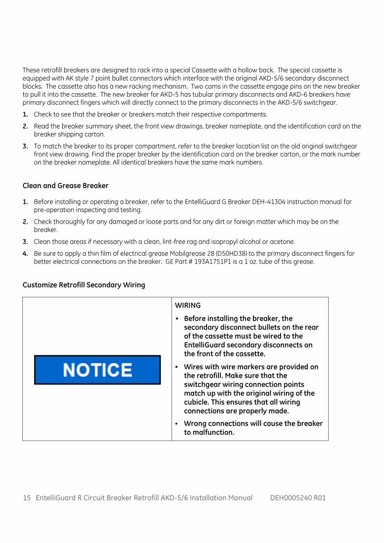
These retrofill breakers are designed to rack into a special Cassette with a hollow back. The special cassette is equipped with AK style 7 point bullet connectors which interface with the original AKD-5/6 secondary disconnect blocks. The cassette also has a new racking mechanism. Two cams in the cassette engage pins on the new breaker to pull it into the cassette. The new breaker for AKD-5 has tubular primary disconnects and AKD-6 breakers have primary disconnect fingers which will directly connect to the primary disconnects in the AKD-5/6 switchgear.
1. Check to see that the breaker or breakers match their respective compartments.
2. Read the breaker summary sheet, the front view drawings, breaker nameplate, and the identification card on the breaker shipping carton.
3. To match the breaker to its proper compartment, refer to the breaker location list on the old original switchgear front view drawing. Find the proper breaker by the identification card on the breaker carton, or the mark number on the breaker nameplate. All identical breakers have the same mark numbers.
Clean and Grease Breaker
1. Before installing or operating a breaker, refer to the EntelliGuard G Breaker DEH-41304 instruction manual for pre-operation inspecting and testing.
2. Check thoroughly for any damaged or loose parts and for any dirt or foreign matter which may be on the breaker.
3. Clean those areas if necessary with a clean, lint-free rag and isopropyl alcohol or acetone.
4. Be sure to apply a thin film of electrical grease Mobilgrease 28 (D50HD38) to the primary disconnect fingers for better electrical connections on the breaker. GE Part # 193A1751P1 is a 1 oz. tube of this grease.
Customize Retrofill Secondary Wiring
WIRING
• Before installing the breaker, the secondary disconnect bullets on the rear of the cassette must be wired to the EntelliGuard secondary disconnects on the front of the cassette.
• Wires with wire markers are provided on the retrofill. Make sure that the switchgear wiring connection points match up with the original wiring of the cubicle. This ensures that all wiring connections are properly made.
• Wrong connections will cause the breaker to malfunction.

16 EntelliGuard R Circuit Breaker Retrofill AKD-5/6 Installation Manual DEH0005240 R01
Modify AKD-5 Switchgear Compartment
Turn OFF/ OPEN the Legacy Circuit Breaker
1. Before modifying the switchgear compartment, de-energize/switch off the breaker. If the circuit breaker is ON and the springs are charged, to turn it off, press the OPEN button on the circuit breaker fascia; and ensure that the circuit breaker contacts are open. Discharge the closing spring before removing the breaker from the switchgear.
Rack Out Legacy Breaker
1. To rack-out legacy (old or original) breaker from the compartment, refer to your legacy-breaker’s manual on how to remove the existing breaker or contact a qualified GE Field Service Engineer.
Empty Compartment—Legacy Breaker Removed
Figure 10 Shows an empty AK75 compartment.
Check, Clean, Grease Compartment
1. Inspect the compartment for damage.
2. Check compartment for suitability of retrofill.
3. Having fully de-energized primary and control power, check each breaker compartment for bolted joints in the primary disconnect bars. Where such joints exist, check the bolts for tightness.
4. Inside the compartment, check the contact areas on each primary disconnect bar or cluster of fingers for foreign matter that may have accumulated. Clean those areas if necessary with a clean, lint-free rag and isopropyl alcohol or acetone.
5. Be sure to apply a thin film of electrical grease Mobilgrease 28 (D50HD38) to the contact areas for better electrical connections inside the compartment.
6. If compartment has a position switch and a position switch actuator will be added to the cassette, see Install Position Switch Actuator section appropriate for the particular frame size breaker.
7. Install the AKD-5 AKD-6 retrofill cassette.
8. Locate and replace Kirk key slide return spring on left side of AK75 and AK100 compartments (supplied with the cassette assembly as a kit). Inspect the Kirk key slide mechanism, grease with Mobilgrease 28 (D50HD38) if required.
9. Install parts to prevent use of the old/original legacy Draw out Mechanism.
Figure 10. AKD-5—Empty Comp’t
17 EntelliGuard R Circuit Breaker Retrofill AKD-5/6 Installation Manual DEH0005240 R01
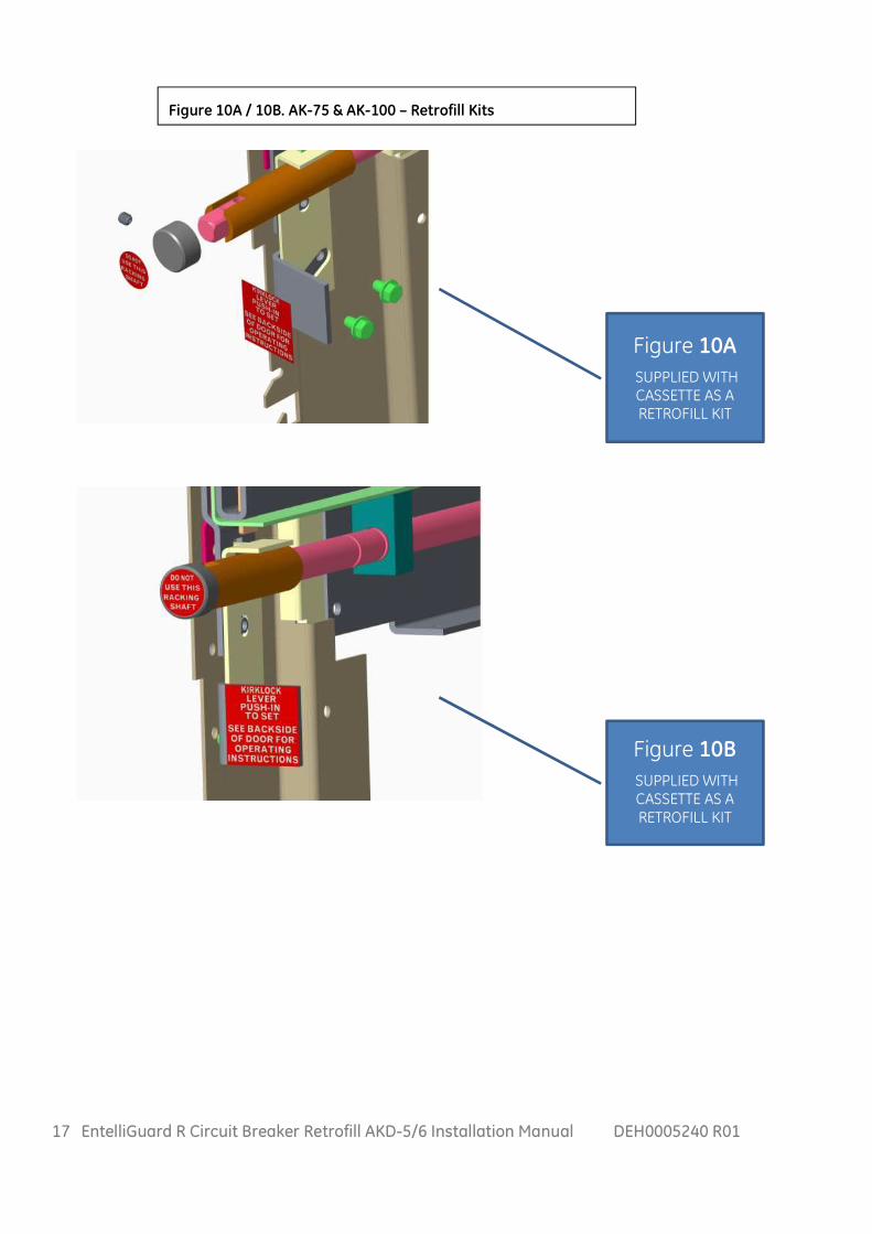
Figure 10A / 10B. AK-75 & AK-100 – Retrofill Kits
Figure 10A
SUPPLIED WITH CASSETTE AS A RETROFILL KIT
Figure 10B
SUPPLIED WITH CASSETTE AS A RETROFILL KIT

18 EntelliGuard R Circuit Breaker Retrofill AKD-5/6 Installation Manual DEH0005240 R01
Figure 11. AKD-5—Cassette
1. Field wire the cassette from the 21 pt bullet sec disc’s to the EntelliGuard front Sec Disc’s Figure 11.
2. Remove Anti-tilt brackets and place the cassette side pins into the rails of the switchgear cabinet.
3. Install Anti-tilt Brackets and NCT adapter/Position switch actuator bracket assembly (Figures 13A-F).
4. Slide the retrofill cassette into the compartment (defeat rail stops on both sides) until dead-stop.
5. Lock the rails of the legacy compartment using both rail locking levers.
6. Disable the legacy racking mechanism and install rail lever lockout brackets ( Figures 10A, 10B &figure14).
Racking-Lock Bracket—Initial Tasks (AK-75, AK-100, AKR-75, AKR-100)
1. Remove existing indicator assembly system from AKD-5/6 cabinet rails .
2. Clean any dirt and debris from rails and kirk interlock slide system.
Install Position Switch Actuator / Neutral CT Adapter Bracket Assembly
AK-75, AK-100, AKR-75, AKR-100 Breaker
Installing the position switch actuator needs to be done after the cassette is installed onto the legacy switchgear rail system. This can be done before pushing the cassette fully into the compartment. Steps of installation for the position switch actuator are as follows.
Figure 12A Figure 12B
Cassette shown with Loading Rails Extended.

19 EntelliGuard R Circuit Breaker Retrofill AKD-5/6 Installation Manual DEH0005240 R01
Position Switch Actuator/ Neutral CT Adapter Bracket Assemblies
Install Kit to Rear of Cassette Table 8.
Legacy Breaker Function Kit Number
AKD-5 3000A and AKD-6 3200A – 4000A Position Switch Actuator 10106054G2
AKD-5 4000A Position Switch Actuator 10106054G3
AKD-5 3000A Position Switch Actuator, N-CT Adapter & Neutral Disconnect
10106054G4
AKD-6 3200A - 4000A Position Switch Actuator, N-CT Adapter & Neutral Disconnect
10106054G5
AKD-5 4000A Position Switch Actuator, N-CT Adapter & Neutral Disconnect
10106054G6
Figure 13A
BRACKET ASSEMBLY AKD-5 and AKD-6 3000A – 4000A RETROFILL - 10106054G2
Figure 13B
BRACKET ASSEMBLY AKD-5 4000A RETROFILL - 10106054G3

20 EntelliGuard R Circuit Breaker Retrofill AKD-5/6 Installation Manual DEH0005240 R01
Figure 13C
NCT BRACKET ASSEMBLY AKD-5 3000A RETROFILL - 10106054G4
Figure 13D
BRACKET ASSEMBLY AKD-6 3200A - 4000A RETROFILL - 10106054G5
Figure 13E
BRACKET ASSEMBLY AKD-5 4000A RETROFILL - 10106054G6
• NCT adapter red wire goes to COM.
• NCT adapter blue wire goes to TAP.
Note: facing into compartment TAP is on the left and COM is on the right.

21 EntelliGuard R Circuit Breaker Retrofill AKD-5/6 Installation Manual DEH0005240 R01
Figure 13F
Install Rail Toggle Lever Lockout Brackets- AK-75, AK-100, AKR-75, AKR-100
Figure 14
INSTALL BRACKETS SUPPLIED WITH CASSETTE AS A RETROFILL KIT IN PLACE
AS SHOWN BOTH SIDES TORQUE (2) ¼-20 BOLTS TO 9.5Nm (85 in-LBF).

22 EntelliGuard R Circuit Breaker Retrofill AKD-5/6 Installation Manual DEH0005240 R01
Install AKD-5 AKD-6 Retrofill Breaker
• It must be ensured that the supply power to the compartment is turned off/ compartment is de-energized for all the incoming and outgoing circuits of the LVS prior to any work being conducted on it.
• During the installation and related work on the equipment, it must be ensured that the operator is using the prescribed PPE for the specified tasks.
• Ensure only qualified personnel install, operate, service, and maintain all electrical equipment.
1. Before inserting the retrofill breaker into the cabinet, make sure that the breaker is switched off. If the spring indicator shows that it is charged, the assembly needs to be discharged, by first switching on the breaker and then switching it off.
2. After installing the cassette, install the breaker assembly by pulling the lifting hooks up (lifting handles, eyes, or ears) from their slots. Use a tool or screwdriver to keep them up, if necessary (Figure 15)
3. Use an appropriate lifting device to install the breaker. See Figure 8 and Figure 9
4. Make sure that the lifting hooks are secured and locked in placed on the breaker.
5. Put the breaker in front of the unit where it is to be installed, leaving enough clearance to swing the compartment door open to access the enclosure. (Figure 16 and Figure 17 ).
6. When the breaker is lined up with the compartment, raise the breaker only slightly higher than the compartment Rails.
Figure 15. AKD-5—Breaker Lifting Holes

23 EntelliGuard R Circuit Breaker Retrofill AKD-5/6 Installation Manual DEH0005240 R01
Figure 16. Cabinet with Compartment Door Closed
Figure 17. Cabinet with Compartment Door Open
7. Check that the cassette is free from obstruction. Figure 17 displays the racking assembly, supporting the new retrofill breaker and Kirk Lock Information Label supplied with AK-75 , AK-100 AKR-75 and AKR-100 Cassettes.
8. Verify that the cassette position indicator shows DISCONNECTED and the racking handle is disengaged.
9. Ensure that the cassette racking cams on both side walls of the cassette are in the completely
Racked-out position.
10. Pull out the two cassette LOADING RAILS to their full extent, horizontal to the ground (Figure 18).
NOTE: Both loading rails should be fully extended and latched or they will not be able to support the breaker.
Figure 18. Racking Arms / Loading Rails, Extended

24 EntelliGuard R Circuit Breaker Retrofill AKD-5/6 Installation Manual DEH0005240 R01
11. Lower the circuit breaker gradually onto the rails. This might need a two-man effort: one to carefully and slowly lower the suspended breaker and the other to guide the breaker into the cassette enclosure.
Figure 19. Breaker Positioned on Rails
12. Using the hand grips on either side, move or push the circuit breaker into the cassette until it reaches a positive stop (the rollers on circuit breaker are engaged with the racking cams of the cassette on both sides). The circuit breaker is now in the DISCONNECTED position (Figure 20).
13. Unlatch and Push back both the extended rails of the cassette to the stowed position.
14. If the circuit breaker is ON, to turn the breaker off, press the OPEN button on the circuit breaker fascia and ensure the circuit breaker contacts are open.
Figure 20. Breaker Ready for Complete Installation
25 EntelliGuard R Circuit Breaker Retrofill AKD-5/6 Installation Manual DEH0005240 R01
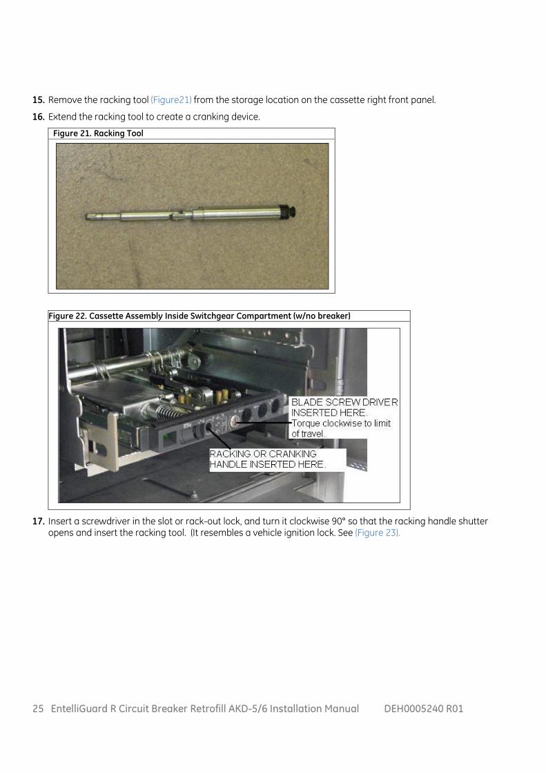
15. Remove the racking tool (Figure21) from the storage location on the cassette right front panel.
16. Extend the racking tool to create a cranking device.
Figure 22. Cassette Assembly Inside Switchgear Compartment (w/no breaker)
17. Insert a screwdriver in the slot or rack-out lock, and turn it clockwise 90° so that the racking handle shutter opens and insert the racking tool. (It resembles a vehicle ignition lock. See (Figure 23).
Figure 21. Racking Tool

26 EntelliGuard R Circuit Breaker Retrofill AKD-5/6 Installation Manual DEH0005240 R01
Figure 23. Shutter
18. Insert the racking tool so that it engages the racking mechanism inside the hole.
19. Crank clockwise to Rack-in the breaker. Rotate ~9 Turns to TEST Position. Rotate clockwise 37 to 37-1/2 total turns to reach the fully CONNECTED Position.
Figure 24. Crank or Racking Handle Inserted
20. As the breaker approaches the TEST position, check the alignment of the fixed and moving parts of the secondary disconnect contacts. (If a motor-spring charge or under-voltage release is installed, the device may operate when approaching the TEST position)
21. Continue rotating the racking handle clockwise until the position indicator first shows TEST, then CONNECTED. When approaching the CONNECTED position, effort to turn the racking handle increases as the primary finger clusters engage.
22. Keep cranking until reaching a positive stop. Full travel is about 37 turns and about 3 turns after the indicator first shows Connected. At this point, the fingers at the back of the circuit breaker should be properly engaged.
23. Using a light and mirror from below the breaker attempt to observe the primary disconnects are making good contact.
24. Remove and store the racking handle in its storage location.
Note that the circuit breaker is now ready for normal operation.

27 EntelliGuard R Circuit Breaker Retrofill AKD-5/6 Installation Manual DEH0005240 R01
AKD-5, AKD-6 – Kirk Key Interlock
The EntelliGuard R retrofill circuit breakers provided as replacements for 3000A-4000A frame circuit breakers have a trip interlock feature which will function using the legacy compartment mounted Key Interlock. A label is provided with full instructions on how to operate the Legacy Key Interlock. It is suggested to apply the label on the inside of the compartment door (Figure 17). Following is a brief summary of how the Key Interlock system is operated.
To activate the key interlock:
1) OPEN the breaker.
2) Rotate the screw on the lower front panel of the cassette which normally allows access to the racking
screw. This will hold the breaker trip free.
3) While the screw is held rotated Clockwise, the Key Interlock slide in the switchgear is pushed inward,
elevating a pin on the left side of the breaker.
4) Turn the key to the key removal position, extending the bolt and lock the breaker in the OPEN position.
Secondary Disconnects, Bullets
The circuit breaker is already wired to the two EntelliGuard R 39 point secondary disconnects . The landing of the wiring on the EntelliGuard R breaker cassette is done in the field. Up to 78 points are available so that all breaker accessories can be wired to dedicated disconnect-points in the cubicle. Each breaker wire is identified with a unique label depict the secondary disconnect assemblies for the AKD-5/6. Figure 25 shows three 7 pt. blocks of legacy type secondary disconnects. The cassette is a separate assembly from the retrofill breaker; first, the cassette is to be wired and then installed in the switchgear, then followed by the breaker being racked into the cassette.
The wiring harness for the secondary disconnects, located on the AKD-5/6 retrofill cassette, has 21 wire connections (grouped in three blocks (A, B, C)) for 75/100, with seven wire connections for each block). Each wire is clearly labeled, or identified, with wire markers or tags. Each wire on the 21-wire harness is connected to a bullet. Each bullet, when the cassette is racked in, engages with its respective points in the switchgear. The wires for Block A are identified as A1, A2,…A7. Block B wiring is likewise labeled as B1, B2, B3,….B7. Block C contains C1, C2,….C7. The end, opposite of the bullets, maps or connects to the retrofill EntelliGuard R Cassette 78-point, secondary-disconnect. For example, if bullets A1 and A4 are reserved for the motor, they connect to points A1 and A2 on the cassette’s 78-point, secondary-disconnect for a motor. Each Cassette secondary wire needs to be landed in the field based on the specifics breakers wiring diagram and modifications made in the field.
Figure 25 is a photo of the AKD-5/6 harness.
Figure 25. AKD-5/6 Harness, Top View of Cassette

28 EntelliGuard R Circuit Breaker Retrofill AKD-5/6 Installation Manual DEH0005240 R01
Figure 26. Example Wiring Diagram for AK25 Secondary Disconnects and Photo Example
Below are tables (Table 9 and Table10) featuring the two 39-blocks (A and B). They make up the 78-point secondary-disconnects.
NOTE:
For Shunt trip > 125Vdc only: Use 2 NO contacts in series with coil. For S/T #1 use 2nd NO contact at terminals B25-B26. (Jumper A21 to B25 and B26 to A5.). For S/T #2 use 2nd NO contact at terminals B17 -B18. (Jumper B20 to B17 and B18 to A12).

29 EntelliGuard R Circuit Breaker Retrofill AKD-5/6 Installation Manual DEH0005240 R01
Table 9. EntelliGuard G 39-Point Secondary A-Block. (Right Front)
Table 10. EntelliGuard G 39-Point Secondary B-Block. (Left Front)

30 EntelliGuard R Circuit Breaker Retrofill AKD-5/6 Installation Manual DEH0005240 R01
Programmer Secondary Disconnect (Breaker Side—N/A)
Programmer secondary disconnects are not provided on AKD5 legacy LVS breakers. If the customer chooses to use the advanced features of the EntelliGuard ACB, the control wiring is routed from the LVS directly to the secondary disconnect landing points on the cassette assembly of the EntelliGuard R cassette. Refer (Table 9 and Table10) featuring the two 39-blocks (A and B) that make up the 78-point secondary-disconnects.
Neutral Disconnect Assembly for Breaker – (Now Mounted to Rear of New Cassette). Refer to Table 8. (4 wire Ground Fault Only)
When a legacy AK or AKR breaker of this type is replaced with a retrofill EntelliGuard R circuit breaker with 4-wire GF in AKD-5 or AKD-6 switchgear, the incoming wires from the neutral CT typically connect to the Equipment Neutral disconnect on the floor of the switchgear compartment. The Equipment Neutral Disconnect must be the type with two spring loaded moving plungers in a phenolic block. The plunger on the left facing into the compartment should be labeled as “TAP” and the plunger to the right should be labeled as “COM”. Older single-Pin type Neutral disconnects similar to an old RCA plug used with Power Sensor cannot be used and must be removed and replaced.
The Equipment Neutral Disconnect’s two plungers that typically mated with two metal straps on a phenolic block (aka the Breaker Neutral Disconnect) will be mating, in the retrofill system, with the “Neutral Disconnect” mounted to a sliding bracket fastened to the rear of the cassette. It will be driven in to mate with the Equipment Neutral Disconnect by the inward motion of the drawout breaker. SeeFigures13A-F.
Neutral Sensors for 4-Wire Ground Fault
The EntelliGuard R retrofill circuit breakers have an EntelliGuard TU Trip Unit that works with Rogowski sensors installed internally on the 3 phases. For 4-wire ground fault it can either work with a Rogowski sensor in the switchgear or it can work with a GE iron core Neutral CT by having its signal modified by GE’s Neutral CT Adapter. The adapter will convert the iron core CT current output to a Rogowski voltage output scaled to match the phase sensors of the breaker.
The neutral CT adapters are not compatible with Neutral CT’s used with “Power Sensor” Trip units or Neutral CT’s used with “SST” trip units. They are compatible with the Neutral CT Assemblies such as TSVG830BK, TSVG832BK and TSVG940BK supplied by GE with all 4-wire Trip Unit Conversion Kits sold since 1983. (The TSVG…BK Neutral CT w/ busbar assemblies were designed for the original MicroVersaTrip Conversion Kits with the same mounting hole patterns as the old SST Neutral Sensors used in AKD-6 switchgear.)
The best approach for most systems is to use an iron core Neutral Sensor compatible with MicroVersaTrip or any newer GE Trip unit (MVT RMS-9, MVT Plus, MVT PM, Power Plus, Pro-Trip, EntelliGuard) and modify the output using the Neutral CT Adapter. This is the only practical way to approach a multi-source ground fault system. Compatible Neutral sensors include the TSVG830BK, TSVG832BK & TSVG940BK listed above or the window type CT’s available since 2014, SSVG830W and SSVG940W. (30=3000A, 32=3200A and 40=4000A CT Rating).

31 EntelliGuard R Circuit Breaker Retrofill AKD-5/6 Installation Manual DEH0005240 R01
Install Neutral Current Transformer Adapter (NCT Adapter) 150A-5000A
This is a miniature Rogowski coil. It mounts between the incoming Neutral disconnect and the breaker trip unit. It converts the signal from an iron Core Neutral sensor to a Rogowski voltage output which is wired to the Breaker's Trip Unit Neutral input connections. It allows a single breaker in an existing M-T-M arrangement to be replaced and operated with an existing 4-wire Multi-Source GF scheme. See Table 8 & Figures13A-F.
The Neutral CT Adapter supports iron core Neutral sensors compatible with MicroVersa Trip, MVT RMS-9, MVT Plus & PM, Power Plus, Pro Trip and EntelliGuard TU rated from 150 to 5000 Amps as used in GE switchboards and switchgear from 1979-2015. It is available in five variations (shown in Table below). Catalog Number Supported Neutral CT ratings (A) RNCTA1200 (R) 600, 1200 RNCTA2000 (R) 150, 200, 400, 800, 1000, 1600, 2000 RNCTA3000 (R) 3000 RNCTA4000 (R) 2500, 3200, 4000 RNCTA5000 (R) 5000
Note: The RNCTA1200 is unique because the Rogowski sensors on the breaker are actually 630A & 1250A rated.
Install Door Interlock System (Cassette Side)
Figure 27 shows the components that make up the AKD-5 retrofill door interlocking assembly:
Figure 27. AKD-5, AKD-6—Door Interlocking Components

32 EntelliGuard R Circuit Breaker Retrofill AKD-5/6 Installation Manual DEH0005240 R01
For the retrofill, instructions for installing the interlocking system on the AKD-5 switchgear are the same as those for EntelliGuard G Circuit Breaker. Install the Door Interlock Lever and torsion spring with an E-ring on pins already found on the cassette side frame. Install the door bracket to holes already located in the retrofill door. For more detailed instructions, refer to the Installation, Operation, and Maintenance Manual for the EntelliGuard G Circuit Breaker, DEH-41304.
Remove and Replace AKD-5—Existing Door
• It must be ensured that the supply power to the compartment is turned off/ compartment is de-energized for all the incoming and outgoing circuits of the LVS prior to any work being conducted on it.
• During the installation and related work on the equipment, it must be ensured that the operator is using the prescribed PPE for the specified tasks.
• Ensure only qualified personnel install, operate, service, and maintain all electrical equipment.
1. To remove existing compartment door(s), refer to your manual on how to remove the legacy doors.
2. To install new door, refer to the Retrofill Door Assemblies, DEH-41563.

33 EntelliGuard R Circuit Breaker Retrofill AKD-5/6 Installation Manual DEH0005240 R01
Programmer disconnect plugs are not used for AKD5/6. Programmer input/output functions are wired directly to the 39 point disconnects on the cassette. Points provided as reference for wiring purposes only.

34 EntelliGuard R Circuit Breaker Retrofill AKD-5/6 Installation Manual DEH0005240 R01

35 EntelliGuard R Circuit Breaker Retrofill AKD-5/6 Installation Manual DEH0005240 R01
GE Energy Connections 41 Woodford Avenue Plainville, CT 06062 www.geindustrial.com
© 2016 General Electric Company
*Trademark of the General Electric Company and/or its subsidiaries DEH0005240 R01 12/16