enhanced stiffness modeling, identification and
TRANSCRIPT
University of Wollongong University of Wollongong
Research Online Research Online
Faculty of Engineering - Papers (Archive) Faculty of Engineering and Information Sciences
August 2005
Enhanced Stiffness Modeling, Identification and Characterization for Robot Enhanced Stiffness Modeling, Identification and Characterization for Robot
Manipulators Manipulators
G. Alici University of Wollongong, [email protected]
B. Shirinzadeh Monash University
Follow this and additional works at: https://ro.uow.edu.au/engpapers
Part of the Engineering Commons
https://ro.uow.edu.au/engpapers/24
Recommended Citation Recommended Citation Alici, G. and Shirinzadeh, B.: Enhanced Stiffness Modeling, Identification and Characterization for Robot Manipulators 2005. https://ro.uow.edu.au/engpapers/24
Research Online is the open access institutional repository for the University of Wollongong. For further information contact the UOW Library: [email protected]
554 IEEE TRANSACTIONS ON ROBOTICS, VOL. 21, NO. 4, AUGUST 2005
Enhanced Stiffness Modeling, Identification andCharacterization for Robot Manipulators
Gürsel Alici and Bijan Shirinzadeh
Abstract—This paper presents the enhanced stiffness modelingand analysis of robot manipulators, and a methodology for theirstiffness identification and characterization. Assuming that themanipulator links are infinitely stiff, the enhanced stiffness modelcontains: 1) the passive and active stiffness of the joints and 2) theactive stiffness created by the change in the manipulator configu-ration, and by external force vector acting upon the manipulatorend point. The stiffness formulation not accounting for the latteris known as conventional stiffness formulation, which is obviouslynot complete and is valid only when: 1) the manipulator is inan unloaded quasistatic configuration and 2) the manipulatorJacobian matrix is constant throughout the workspace. Theexperimental system considered in this study is a Motoman SK120 robot manipulator with a closed-chain mechanism. While thedeflection of the manipulator end point under a range of externalforces is provided by a high precision laser measurement system,a wrist force/torque sensor measures the external forces. Based onthe experimental data and the enhanced stiffness model, the jointstiffness values are first identified. These stiffness values are thenused to prove that conventional stiffness modeling is incomplete.Finally, they are employed to characterize stiffness properties ofthe robot manipulator. It has been found that although the compo-nent of the stiffness matrix differentiating the enhanced stiffnessmodel from the conventional one is not always positive definite, theresulting stiffness matrix can still be positive definite. This followsthat stability of the stiffness matrix is not influenced by this stiff-ness component. This study contributes to the previously reportedwork from the point of view of using the enhanced stiffness modelfor stiffness identification, verification and characterization, andof new experimental results proving that the conventional stiffnessmatrix is not complete and is valid under certain assumptions.
Index Terms—Compliance/force control, manipulator kine-matic, stiffness identification, stiffness modeling.
I. INTRODUCTION
KNOWING the stiffness or compliance of a robot manip-ulator reflected at its end point is of prime importance
to successfully conduct contact and noncontact tasks. In fact,the stiffness of robot manipulators generally represents theaccuracy required to satisfy the desired position and forcecommands [1]–[3]. Further, it must be recalled that there is
Manuscript received May 4, 2004; revised August 4, 2004. This paper wasrecommended for publication by Associate Editor R. Roberts and Editor I.Walker upon evaluation of the reviewers’ comments. This work was supportedin part by the Australian Research Council (ARC) and Monash University(SMURF2).
G. Alici is with the School of Mechanical, Materials and Mechatronics Engi-neering, University of Wollongong, Wollongong, NSW 2522, Australia (e-mail:[email protected]).
B. Shirinzadeh is with Robotics and Mechatronics Research Laboratory, De-partment of Mechanical Engineering, Monash University, Melbourne, Victoria3800, Australia (e-mail: [email protected]).
Digital Object Identifier 10.1109/TRO.2004.842347
coupling among rotational and translational Cartesian move-ments of a typical serially connected robot manipulator becauseof the inconsistency between the task specification (Cartesian)space and the actuation (joint) space. This coupling also showsitself in the nondiagonal stiffness matrix seen at the end pointof the robot manipulator. As a result, the manipulator toolframe rotates when an end point force is applied along oneof the degrees of freedom [1], [2]. If the stiffness seen at themanipulator end point is modeled and identified accurately, itwould be possible to compensate for the coupling and posingerrors caused by the external forces. The model may also beused to generate manipulator stiffness maps defining the ma-nipulator end point stiffness as functions of the joint stiffnessand manipulator configurations. The minimum and maximumstiffness values, which are the maximum and minimum eigen-values of the stiffness matrix, and their directions, which arethe corresponding eigenvectors, can be known in advance.Hence, the most appropriate configurations for certain taskscan be selected. In this study, we, therefore, address enhancedstiffness modeling, analysis, identification and characterizationfor robot manipulators. The enhanced stiffness model differsfrom the conventional stiffness model first derived by Masonand Salisbury [4] such that it contains the stiffness componentdue to the change in the manipulator configuration and theexternal forces acting on the manipulator in addition to theinherent stiffness of the system. The conventional stiffnessformulation is valid only when the manipulator is in a qua-sistatic configuration with no loading, or when it has a constantJacobian matrix throughout its workspace such as a Cartesianrobot manipulator. Although the existence of the additionalstiffness component has been known for a long time [5], [6],its importance for preserving the conservative and fundamentalproperties of joint and Cartesian stiffness matrices has beenhighlighted by Kao et al. [9] and others [7], [8], and [10]recently.
Stiffness modeling, analysis, synthesis and control haveattracted the attention of many researchers. Ang and Andeen[11] reported on how to generate variable passive compliancethrough the topology of robot manipulators with backdrivableactuators. It has been concluded that a nondiagonal stiffnessmatrix can be effective in preventing jamming and contact in-duced vibrations. Ang et al. [12] also introduced a methodologyto model the end-effector stiffness due to link flexibilities ofserially connected robot manipulators. They demonstrated thatthe methodology could be applied to all possible serial manip-ulator topologies: 1) to describe their end-effector stiffness asa function of manipulator configurations, and 2) to choose themost appropriate manipulator configuration compatible withthe compliance requirements of the task at hand. Kao et al.
1552-3098/$20.00 © 2005 IEEE
ALICI AND SHIRINZADEH: ENHANCED STIFFNESS MODELLING ROBOT MANIPULATORS 555
[13] have pointed out that the linear 3 3 stiffness matrices forgrasping can be decomposed into symmetric and nonsymmetriccomponents such that they provide better physical insights intostiffness control and grasping. The stiffness components arecalibrated using experimental data from some grasping tasks. Ithas been concluded that the stiffness matrix has a significant ef-fect on grasp stability and robustness against slipping. Hang andSchimmels [14] demonstrated that spatial compliance behaviorcould be accomplished using a number of springs connected inparallel to a rigid body. In a study on global stiffness modelingof compliant couplings, Griffis and Duffy [15] pointed outthat a 6 6 general stiffness matrix was not symmetric for aconservative system. Ciblak and Lipkin [16] later demonstratedthat the skew-symmetric part of such a matrix was due to theexternally applied force/moment vectors. Ciblak and Lipkin[17] also employed the spatial vector (screw) algebra to demon-strate that the Cartesian stiffness of robotic systems could berealized by a number of springs. Chen and Kao [7] have recentlyreported that the conventional stiffness formulation derived byMason and Salisbury [4] is not valid and a new conservativecongruence transformation must be used as the generalizedrelationship between the joint and Cartesian stiffness matricesin order to preserve the fundamental properties of the stiffnessmatrices. Based on this finding, a number of publications onthe use of this new transformation have been made availableby the same group of researchers [7]–[10], simulation resultsfor a planar revolute-jointed manipulator have been providedto demonstrate its validity. With this in mind, it is believed thatthe work presented in this paper is the first to verify enhancedstiffness modeling through experimental results provided by ahigh-resolution laser-based position sensing and measurementsystem.
The sources of the stiffness of a typical robot manipulatorare the compliance of its joints, actuators and other transmis-sion elements, geometric and material properties of the links,base, and the active stiffness provided by its position controlsystem. For the purpose of this study, we assume that: 1) thecompliance in actuators and transmission elements is the dom-inant source of the stiffness, and it can be represented by alinear torsional spring for each joint; 2) the active compliancein actuators due to a robot position control system provided bythe original equipment manufacturer does not vary with timethough an integral controller can increase the active compli-ance, depending on the positioning error; and 3) the links areinfinitely stiff. The experimental system employed here in thiswork is a Motoman SK 120 robot manipulator, which is not asimple open chain robot manipulator, but rather contains a par-allel five-bar mechanism to increase the structural stiffness ofthe system [18]. In order to identify the joint stiffness values, anumber of manipulator configurations are heuristically selectedto acquire experimental position and force data, which are pro-vided by a laser-based sensing and measurement system, anda wrist force/torque (F/T) sensor, respectively. The laser-basedsensing system has an accuracy of ppm m/m , a coordi-nate repeatability of ppm m/m and a distance resolutionof 1.26 m, and can measure the position of any target along thethree orthogonal axes. A classical nonlinear least square estima-tion algorithm is used to estimate the joint stiffness values. Theestimated joint stiffness matrix is verified experimentally. Also,
the work done in Cartesian and joint spaces are computed forboth enhanced and conventional stiffness formulations. It hasbeen found that the conventional stiffness formulation does notsatisfy the principle of the conservation of energy. It has alsobeen demonstrated that this arises from the existence of the ad-ditional stiffness component. Further, based on the estimatedjoint stiffness constants, the limits and conditions of the posi-tive definiteness (stability) of the Cartesian stiffness matrix areevaluated. It has been found that although the additional stiff-ness component differentiating the enhanced formulation fromthe conventional formulation is not always positive definite, theresulting Cartesian stiffness matrix can still be positive definite.The main contribution of this study is the new theoretical and ex-perimental results supporting the enhanced stiffness modeling(or conservative congruence transformation) through stiffnessidentification, verification, and characterization.
II. KINEMATIC ANALYSES AND JACOBIAN MATRIX
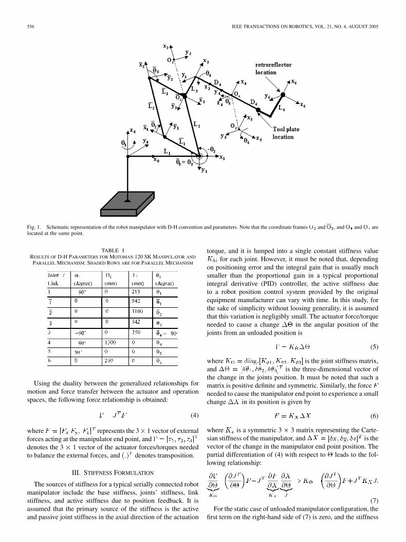
The schematic of the robot manipulator and the coordinateframes needed to generate a kinematic model based on De-navit–Hartenberg parameters is depicted in Fig. 1. The manip-ulator possesses a parallel five-bar mechanism. Therefore, thekinematic model of the parallel five-bar mechanism is also de-rived. The Denavit Hartenberg parameters for the manipulatorand the parallel mechanism are given in Table I.
An L-shaped apparatus with a longitudinal extension ofmm from the manipulator tool plate and a vertical offset
of mm from the longitudinal axis of the tool plateis connected to the manipulator tool plate in order to securethe retroreflector of the measurement system to the robot viaa 3-point-contact magnetic fixture. With reference to Fig. 1, itmust be noted that, for the five-bar mechanism, ,
, , , and . The homogeneoustransformation matrix between the frames 1 and 2 of the five baris described in terms of the coordinate frames fixed to the linksof the five-bar mechanism as
(1)
The overall transformation matrix between the base coordi-nate frame and the frame fixed to the manipulator end point iswritten as
(2)
where is the homogeneous transformation matrix be-tween two consecutive coordinate frames j and basedon Denavit–Hartenberg convention [18]. From the first threeelements of the last column of , the generalized relationshipbetween the input velocity vector and theoutput velocity vector is obtained as
(3)where is the manipulator Jacobian matrix, see Appendix I foranalytical expressions of its elements.
556 IEEE TRANSACTIONS ON ROBOTICS, VOL. 21, NO. 4, AUGUST 2005
Fig. 1. Schematic representation of the robot manipulator with D-H convention and parameters. Note that the coordinate framesO andO , andO andO arelocated at the same point.
TABLE IRESULTS OF D-H PARAMETERS FOR MOTOMAN 120 SK MANIPULATOR AND
PARALLEL MECHANISM. SHADED ROWS ARE FOR PARALLEL MECHANISM
Using the duality between the generalized relationships formotion and force transfer between the actuator and operationspaces, the following force relationship is obtained:
(4)
where represents the 3 1 vector of externalforces acting at the manipulator end point, anddenotes the 3 1 vector of the actuator forces/torques neededto balance the external forces, and denotes transposition.
III. STIFFNESS FORMULATION
The sources of stiffness for a typical serially connected robotmanipulator include the base stiffness, joints’ stiffness, linkstiffness, and active stiffness due to position feedback. It isassumed that the primary source of the stiffness is the activeand passive joint stiffness in the axial direction of the actuation
torque, and it is lumped into a single constant stiffness valuefor each joint. However, it must be noted that, depending
on positioning error and the integral gain that is usually muchsmaller than the proportional gain in a typical proportionalintegral derivative (PID) controller, the active stiffness dueto a robot position control system provided by the originalequipment manufacturer can vary with time. In this study, forthe sake of simplicity without loosing generality, it is assumedthat this variation is negligibly small. The actuator force/torqueneeded to cause a change in the angular position of thejoints from an unloaded position is
(5)
where is the joint stiffness matrix,and is the three-dimensional vector ofthe change in the joints position. It must be noted that such amatrix is positive definite and symmetric. Similarly, the forceneeded to cause the manipulator end point to experience a smallchange in its position is given by
(6)
where is a symmetric 3 3 matrix representing the Carte-sian stiffness of the manipulator, and is thevector of the change in the manipulator end point position. Thepartial differentiation of (4) with respect to leads to the fol-lowing relationship:
(7)For the static case of unloaded manipulator configuration, the
first term on the right-hand side of (7) is zero, and the stiffness
ALICI AND SHIRINZADEH: ENHANCED STIFFNESS MODELLING ROBOT MANIPULATORS 557
seen at the end point of the manipulator can be expressedas
(8)
Equation (8) is the formulation of active stiffness control[4], which regulates the apparent stiffness of a manipulatorend point in order to control the nominal position of the endpoint. Stiffness values are changed in the software to satisfythe desired position commands. It must be noted thatcalculated from (8) is the Cartesian stiffness matrix basedon the conventional stiffness formulation, which neglects thestiffness component due to external loading and change inthe manipulator configuration.
If any positive definite and symmetric matrix is subjectedto a transformation operation in the form of , the re-sulting matrix will still be positive definite and symmetric, aslong as the transformation matrix is nonsingular [19]. Thismeans that the stiffness matrix evaluated from (8) is posi-tive definite and symmetric. As provided in [7], [20], the matrixresulting from the first part of (7) is symmetric, but dependingon the external forces/payloads and the configuration of the ma-nipulator, it can be positive definite or not. With regard to thesecond part of (7), the fundamental properties of such asits definiteness and symmetry are preserved provided that theJacobian matrix J is not singular. With this in mind, (7) alwaysgives a symmetric stiffness matrix , but not necessarily a pos-itive definite . However, as explained above, the joint stiff-ness matrix is the natural entity of a robot manipulator and doesnot change with the manipulator configuration. Further, it is a di-agonal and positive definite matrix. Therefore, the fundamentalproperties of the Cartesian stiffness matrix can be evaluated forany existing robot manipulator.
IV. ESTIMATION OF JOINT STIFFNESS
The enhanced stiffness formulation given by (7) differs fromthe conventional stiffness formulation in the sense that its firstpart stands for the case when the manipulator is externallyloaded and/or the manipulator Jacobian changes with its con-figuration. This part of (7) completes the conventional jointstiffness matrix and therefore, we call it the complementarystiffness matrix , and for a manipulator actuated throughthree joints, it can be written as
(9)
where is a 3 1 column vector. From (7), thecomplete stiffness matrix of the manipulator in Cartesian spaceis obtained as
(10)
The force vector can be a dynamic force or a static forcesuch as a payload carried by the manipulator. In this study, it isassumed that it is in the form of . Such a forcevector will generate a deflection of , whichis a positioning error. If the joint stiffness values are iden-tified accurately using some experimental deflection and forcedata, the stiffness can subsequently be calculated from (7)
for any external force vector without needing any other exper-imental data. By substituting (10) into (6) and solving forgives
(11)
For a given manipulator configuration where a force vectorcauses the deflection vector , (11) is nonlinear with un-
known joint stiffness values, which can be estimated usinga least squares estimation algorithm. Since the stiffness of ajoint is a local property, and the topology of a revolute jointdoes not change with the movement of the manipulator, it isassumed that the stiffness matrix is constant for revolutejointed manipulators.
A. Nonlinear Least Square
Based on the nonlinear deflection model of the ma-nipulator expressed with (11), the joint stiffness values areestimated by minimizing the summed square of the error vectorassociated with number of measurements
(12)
where is the error vector given by
(13)
is the measured (true) end point deflection vector undera range of payloads, and is the deflection vector cal-culated from (11) for the same payload. This is basicallya nonlinear least square optimization problem that can besolved using either the interior-reflective Newton method orLevenburg–Marquardt algorithm. These are two efficient op-timization algorithms for large-scale nonlinear problems. Theformer, which is based on the method of preconditioned con-jugate gradients, can solve difficult nonlinear problems moreefficiently than the latter [21]. In this study, both algorithmsare implemented for the nonlinear least square estimation ofthe parameters. The solutions converged to the same numericalvalues. The procedure was realized iteratively until the deflec-tion error was small enough to meet a termination condition of
.
B. Experimental Setup and Results
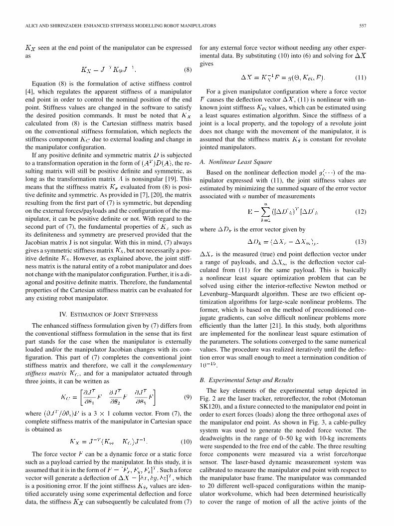
The key elements of the experimental setup depicted inFig. 2 are the laser tracker, retroreflector, the robot (MotomanSK120), and a fixture connected to the manipulator end point inorder to exert forces (loads) along the three orthogonal axes ofthe manipulator end point. As shown in Fig. 3, a cable-pulleysystem was used to generate the needed force vector. Thedeadweights in the range of 0–50 kg with 10-kg incrementswere suspended to the free end of the cable. The three resultingforce components were measured via a wrist force/torquesensor. The laser-based dynamic measurement system wascalibrated to measure the manipulator end point with respect tothe manipulator base frame. The manipulator was commandedto 20 different well-spaced configurations within the manip-ulator workvolume, which had been determined heuristicallyto cover the range of motion of all the active joints of the
558 IEEE TRANSACTIONS ON ROBOTICS, VOL. 21, NO. 4, AUGUST 2005
Fig. 2. Experimental setup.
Fig. 3. Schematic of loading setup.
manipulator. The position of the manipulator joints responsiblefor the orientation were such that the manipulator end pointwas always perpendicular to the ground during the course ofthis research. The manipulator position controller is the oneprovided by the original equipment manufacturer. In order tominimize the effects of measurement noise, the PC-based datameasurement and recording system of the laser tracker takes100 measurements for the same configuration and providesthe average of these measurements as the measurand. For eachselected configuration, first of all, the Cartesian position of themanipulator end point without payload was recorded by thelaser tracker, and followed by measurements of the Cartesianposition of the manipulator for each level of payload, and finallythe difference between the unloaded and loaded measurementswere taken to obtain the deflection data for that particular forcevector.
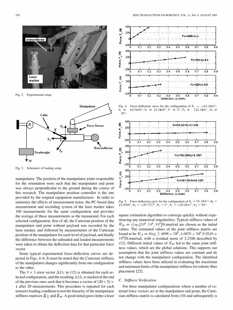
Some typical experimental force-deflection curves are de-picted in Figs. 4–6. It must be noted that the Cartesian stiffnessof the manipulator changes significantly from one configurationto the other.
The 3 1 error vector in (12) is obtained for each se-lected configuration, and the resulting is stacked at the endof the previous ones such that it becomes a vector of
after 20 measurements. This procedure is repeated for eachnonzero loading condition to test the linearity of the manipulatorstiffness matrices and . A good initial guess helps a least
Fig. 4. Force-deflection curve for the configuration of � = �89:3803 ,� = �62:9809 , � = 21:2489 , � = 0 , � = �111:2492 , � =
�90 .
Fig. 5. Force-deflection curve for the configuration of � = 98:1065 , � =
23:2088 , � = �20:7957 , � = 0 , � = �69:2041 , � = 90 .
square estimation algorithm to converge quickly without expe-riencing any numerical singularities. Typical stiffness values of
N.mm/rad are chosen as the initialvalues. The estimated values of the joint stiffness matrix arefound to be
N.mm/rad, with a residual norm of 2.2106 described by(12). Different initial values of led to the same joint stiff-ness values, which are the global solutions. This supports ourassumption that the joint stiffness values are constant and donot change with the manipulator configuration. The identifiedstiffness values have been utilized in evaluating the maximumand minimum limits of the manipulator stiffness for robotic fiberplacement [22].
C. Stiffness Verification
For three manipulator configurations where a number of ex-ternal force vectors act at the manipulator end point, the Carte-sian stiffness matrix is calculated from (10) and subsequently is
ALICI AND SHIRINZADEH: ENHANCED STIFFNESS MODELLING ROBOT MANIPULATORS 559
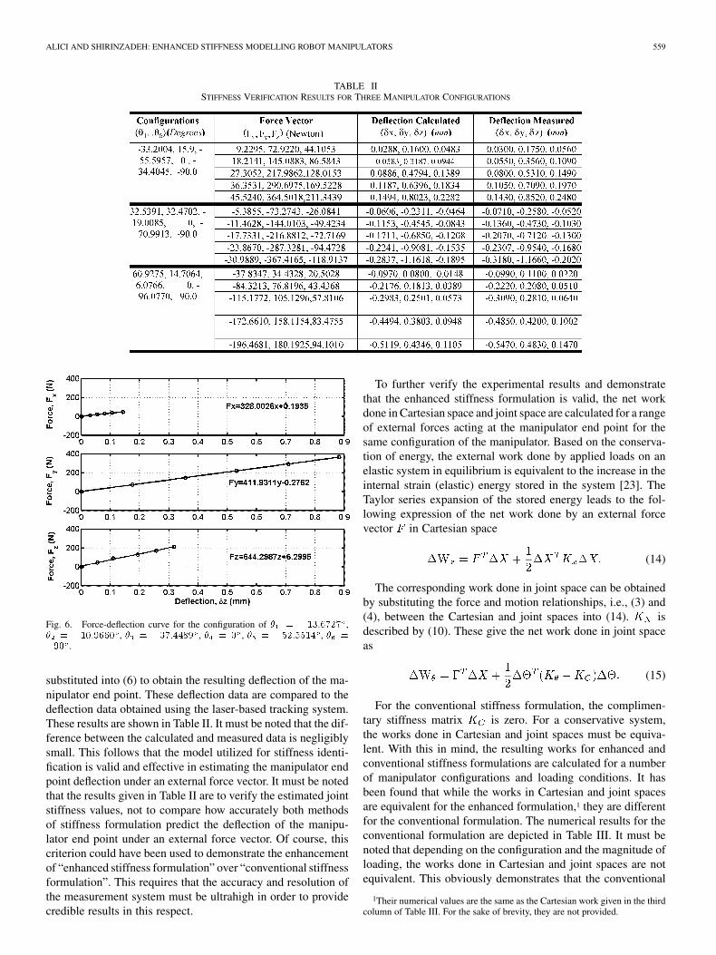
TABLE IISTIFFNESS VERIFICATION RESULTS FOR THREE MANIPULATOR CONFIGURATIONS
Fig. 6. Force-deflection curve for the configuration of � = �13:6727 ,� = �10:9660 , � = �37:4489 , � = 0 , � = �52:5514 , � =
�90 .
substituted into (6) to obtain the resulting deflection of the ma-nipulator end point. These deflection data are compared to thedeflection data obtained using the laser-based tracking system.These results are shown in Table II. It must be noted that the dif-ference between the calculated and measured data is negligiblysmall. This follows that the model utilized for stiffness identi-fication is valid and effective in estimating the manipulator endpoint deflection under an external force vector. It must be notedthat the results given in Table II are to verify the estimated jointstiffness values, not to compare how accurately both methodsof stiffness formulation predict the deflection of the manipu-lator end point under an external force vector. Of course, thiscriterion could have been used to demonstrate the enhancementof “enhanced stiffness formulation” over “conventional stiffnessformulation”. This requires that the accuracy and resolution ofthe measurement system must be ultrahigh in order to providecredible results in this respect.
To further verify the experimental results and demonstratethat the enhanced stiffness formulation is valid, the net workdone in Cartesian space and joint space are calculated for a rangeof external forces acting at the manipulator end point for thesame configuration of the manipulator. Based on the conserva-tion of energy, the external work done by applied loads on anelastic system in equilibrium is equivalent to the increase in theinternal strain (elastic) energy stored in the system [23]. TheTaylor series expansion of the stored energy leads to the fol-lowing expression of the net work done by an external forcevector in Cartesian space
(14)
The corresponding work done in joint space can be obtainedby substituting the force and motion relationships, i.e., (3) and(4), between the Cartesian and joint spaces into (14). isdescribed by (10). These give the net work done in joint spaceas
(15)
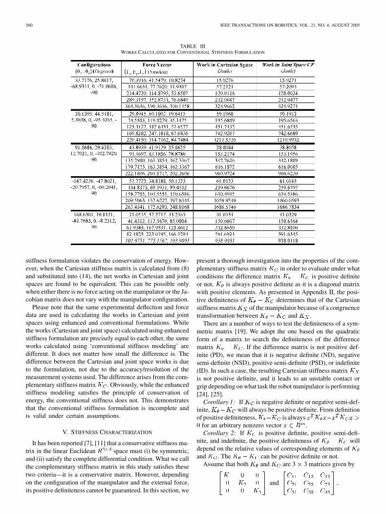
For the conventional stiffness formulation, the complimen-tary stiffness matrix is zero. For a conservative system,the works done in Cartesian and joint spaces must be equiva-lent. With this in mind, the resulting works for enhanced andconventional stiffness formulations are calculated for a numberof manipulator configurations and loading conditions. It hasbeen found that while the works in Cartesian and joint spacesare equivalent for the enhanced formulation,1 they are differentfor the conventional formulation. The numerical results for theconventional formulation are depicted in Table III. It must benoted that depending on the configuration and the magnitude ofloading, the works done in Cartesian and joint spaces are notequivalent. This obviously demonstrates that the conventional
1Their numerical values are the same as the Cartesian work given in the thirdcolumn of Table III. For the sake of brevity, they are not provided.
560 IEEE TRANSACTIONS ON ROBOTICS, VOL. 21, NO. 4, AUGUST 2005
TABLE IIIWORKS CALCULATED FOR CONVENTIONAL STIFFNESS FORMULATION
stiffness formulation violates the conservation of energy. How-ever, when the Cartesian stiffness matrix is calculated from (8)and substituted into (14), the net works in Cartesian and jointspaces are found to be equivalent. This can be possible onlywhen either there is no force acting on the manipulator or the Ja-cobian matrix does not vary with the manipulator configuration.
Please note that the same experimental deflection and forcedata are used in calculating the works in Cartesian and jointspaces using enhanced and conventional formulations. Whilethe works (Cartesian and joint space) calculated using enhancedstiffness formulation are precisely equal to each other, the sameworks calculated using ‘conventional stiffness modeling’ aredifferent. It does not matter how small the difference is. Thedifference between the Cartesian and joint space works is dueto the formulation, not due to the accuracy/resolution of themeasurement systems used. The difference arises from the com-plementary stiffness matrix . Obviously, while the enhancedstiffness modeling satisfies the principle of conservation ofenergy, the conventional stiffness does not. This demonstratesthat the conventional stiffness formulation is incomplete andis valid under certain assumptions.
V. STIFFNESS CHARACTERIZATION
It has been reported [7], [11] that a conservative stiffness ma-trix in the linear Euclidean space must (i) be symmetric,and (ii) satisfy the complete differential condition. What we callthe complementary stiffness matrix in this study satisfies thesetwo criteria—it is a conservative matrix. However, dependingon the configuration of the manipulator and the external force,its positive definiteness cannot be guaranteed. In this section, we
present a thorough investigation into the properties of the com-plementary stiffness matrix in order to evaluate under whatconditions the difference matrix is positive definiteor not. is always positive definite as it is a diagonal matrixwith positive elements. As presented in Appendix II, the posi-tive definiteness of determines that of the Cartesianstiffness matrix of the manipulator because of a congruencetransformation between and .
There are a number of ways to test the definiteness of a sym-metric matrix [19]. We adopt the one based on the quadraticform of a matrix to search the definiteness of the differencematrix . If the difference matrix is not positive def-inite (PD), we mean that it is negative definite (ND), negativesemi-definite (NSD), positive semi-definite (PSD), or indefinite(ID). In such a case, the resulting Cartesian stiffness matrixis not positive definite, and it leads to an unstable contact orgrip depending on what task the robot manipulator is performing[24], [25].
Corollary 1: If is negative definite or negative semi-def-inite, will always be positive definite. From definitionof positive definiteness, is always
for an arbitrary nonzero vector .Corollary 2: If is positive definite, positive semi-defi-
nite, and indefinite, the positive definiteness of willdepend on the relative values of corresponding elements ofand . The can be positive definite or not.
Assume that both and are 3 3 matrices given by
and
ALICI AND SHIRINZADEH: ENHANCED STIFFNESS MODELLING ROBOT MANIPULATORS 561
TABLE IVRESULTS OF DEFINITENESS TEST FOR MATRIX K FOR EIGHT DIFFERENT LOADING CASES
For a positive definite , the following three condi-tions (the determinants of the primary minors) have to be satis-fied simultaneously as follows.
i) .ii) .iii)
.
If any of these conditions is not satisfied, will notbe positive definite. This method of testing the definiteness ofa matrix is deliberately followed to quantify the order of theexternal forces needed to generate a nonpositive definite
, as numerically demonstrated in Section VI.
VI. COMPUTATIONAL ANALYSIS
The definiteness of the matrix depends on the ma-nipulator configuration and the magnitude and direction ofthe external force vector. For the identified joint stiffnessmatrix
N.mm/rad, and a range of external forces acting on themanipulator, the definiteness of is evaluated numerically.The manipulator has the motion ranges of ,
, and for its first threejoints. These motion ranges are implemented with a step sizeof 0.2 radian or 11.46 . It is assumed that the magnitude ofeach component of the force vector is 100 Newton with thefollowing directions.
1) All of the components , , are positive.2) All of the components , , are negative.3) is negative, and are positive.4) is negative, and are positive.5) is negative, and are positive.6) is positive, and are negative.7) is positive, and are negative.8) is positive, and are negative.For the specified conditions and numerical values, the defi-
niteness of and are determined. The definitenesstest results for are shown in Table IV in terms of thenumber of positive definite (PD) and nonpositive definite con-figurations for the eight loading conditions (force applicationdirections) outlined above. It must be noted that is not
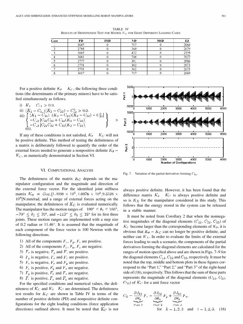
Fig. 7. Variation of the partial derivatives forming C .
always positive definite. However, it has been found that thedifference matrix is always positive definite andso is for the manipulator considered in this study. Thisfollows that the energy stored in the system can be releasedin a stable manner.
It must be noted from Corollary 2 that when the nonnega-tive magnitudes of the diagonal elements ( , , ) of
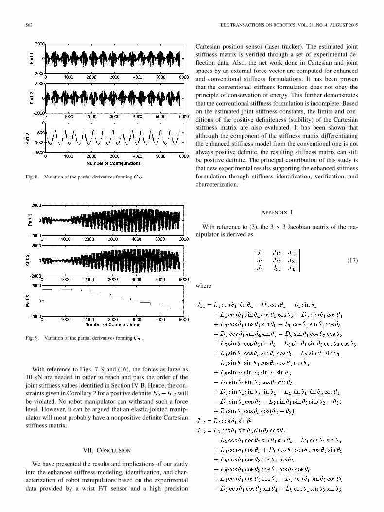
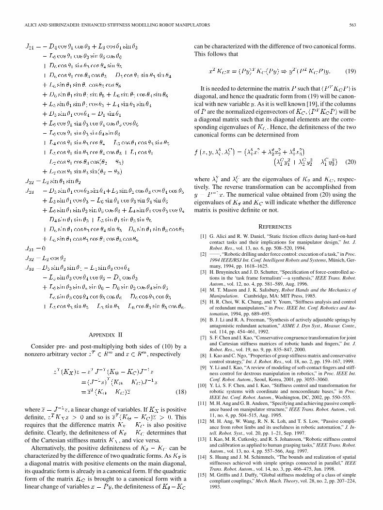
become larger than the corresponding elements of , it isobvious that can no longer be positive definite, andneither can . In order to evaluate the limits of the externalforces leading to such a scenario, the components of the partialderivatives forming the diagonal elements are calculated for theranges of motion specified above and are shown in Figs. 7–9 forthe diagonal elements , and , respectively. It must benoted that the top, middle and bottom plots in these figures cor-respond to the “Part 1,” “Part 2,” and “Part 3” of the right-handside of (16), respectively. This follows that the sum of these partsrepresents the magnitude of the diagonal elements ( , ,
) of for a unit force vector
for and (16)
562 IEEE TRANSACTIONS ON ROBOTICS, VOL. 21, NO. 4, AUGUST 2005
Fig. 8. Variation of the partial derivatives forming C .
Fig. 9. Variation of the partial derivatives forming C .
With reference to Figs. 7–9 and (16), the forces as large as10 kN are needed in order to reach and pass the order of thejoint stiffness values identified in Section IV-B. Hence, the con-straints given in Corollary 2 for a positive definite willbe violated. No robot manipulator can withstand such a forcelevel. However, it can be argued that an elastic-jointed manip-ulator will most probably have a nonpositive definite Cartesianstiffness matrix.
VII. CONCLUSION
We have presented the results and implications of our studyinto the enhanced stiffness modeling, identification, and char-acterization of robot manipulators based on the experimentaldata provided by a wrist F/T sensor and a high precision
Cartesian position sensor (laser tracker). The estimated jointstiffness matrix is verified through a set of experimental de-flection data. Also, the net work done in Cartesian and jointspaces by an external force vector are computed for enhancedand conventional stiffness formulations. It has been proventhat the conventional stiffness formulation does not obey theprinciple of conservation of energy. This further demonstratesthat the conventional stiffness formulation is incomplete. Basedon the estimated joint stiffness constants, the limits and con-ditions of the positive definiteness (stability) of the Cartesianstiffness matrix are also evaluated. It has been shown thatalthough the component of the stiffness matrix differentiatingthe enhanced stiffness model from the conventional one is notalways positive definite, the resulting stiffness matrix can stillbe positive definite. The principal contribution of this study isthat new experimental results supporting the enhanced stiffnessformulation through stiffness identification, verification, andcharacterization.
APPENDIX I
With reference to (3), the 3 3 Jacobian matrix of the ma-nipulator is derived as
(17)
where
ALICI AND SHIRINZADEH: ENHANCED STIFFNESS MODELLING ROBOT MANIPULATORS 563
APPENDIX II
Consider pre- and post-multiplying both sides of (10) by anonzero arbitrary vector and , respectively
(18)
where , a linear change of variables. If is positivedefinite, and so is . Thisrequires that the difference matrix is also positivedefinite. Clearly, the definiteness of determines thatof the Cartesian stiffness matrix , and vice versa.
Alternatively, the positive definiteness of can becharacterized by the difference of two quadratic forms. As isa diagonal matrix with positive elements on the main diagonal,its quadratic form is already in a canonical form. If the quadraticform of the matrix is brought to a canonical form with alinear change of variables , the definiteness of
can be characterized with the difference of two canonical forms.This follows that
(19)
It is needed to determine the matrix such that isdiagonal, and hence the quadratic form from (19) will be canon-ical with new variable . As it is well known [19], if the columnsof are the normalized eigenvectors of , will bea diagonal matrix such that its diagonal elements are the corre-sponding eigenvalues of . Hence, the definiteness of the twocanonical forms can be determined from
(20)
where and are the eigenvalues of and , respec-tively. The reverse transformation can be accomplished from
. The numerical value obtained from (20) using theeigenvalues of and will indicate whether the differencematrix is positive definite or not.
REFERENCES
[1] G. Alici and R. W. Daniel, “Static friction effects during hard-on-hardcontact tasks and their implications for manipulator design,” Int. J.Robot. Res., vol. 13, no. 6, pp. 508–520, 1994.
[2] , “Robotic drilling under force control: execution of a task,” in Proc.1994 IEEE/RSJ Int. Conf. Intelligent Robots and Systems, Münich, Ger-many, 1994, pp. 1618–1625.
[3] H. Bruyninckx and J. D. Schutter, “Specification of force-controlled ac-tions in the ‘task frame formalism’—a synthesis,” IEEE Trans. Robot.Autom., vol. 12, no. 4, pp. 581–589, Aug. 1996.
[4] M. T. Mason and J. K. Salisbury, Robot Hands and the Mechanics ofManipulation. Cambridge, MA: MIT Press, 1985.
[5] H. R. Choi, W. K. Chung, and Y. Youm, “Stiffness analysis and controlof redundant manipulators,” in Proc. IEEE Int. Conf. Robotics and Au-tomation, 1994, pp. 689–695.
[6] B. J. Li and R. A. Freeman, “Synthesis of actively adjustable springs byantagonistic redundant actuation,” ASME J. Dyn Syst., Measur. Contr.,vol. 114, pp. 454–461, 1992.
[7] S. F. Chen and I. Kao, “Conservative congruence transformation for jointand Cartesian stiffness matrices of robotic hands and fingers,” Int. J.Robot. Res., vol. 19, no. 9, pp. 835–847, 2000.
[8] I. Kao and C. Ngo, “Properties of grasp stiffness matrix and conservativecontrol strategy,” Int. J. Robot. Res., vol. 18, no. 2, pp. 159–167, 1999.
[9] Y. Li and I. Kao, “A review of modeling of soft-contact fingers and stiff-ness control for dextrous manipulation in robotics,” in Proc. IEEE Int.Conf. Robot. Autom., Seoul, Korea, 2001, pp. 3055–3060.
[10] Y. Li, S. F. Chen, and I. Kao, “Stiffness control and transformation forrobotic systems with coordinate and noncoordinate bases,” in Proc.IEEE Int. Conf. Robot. Autom., Washington, DC, 2002, pp. 550–555.
[11] M. H. Ang and G. B. Andeen, “Specifying and achieving passive compli-ance based on manipulator structure,” IEEE Trans. Robot. Autom., vol.11, no. 4, pp. 504–515, Aug. 1995.
[12] M. H. Ang, W. Wang, R. N. K. Loh, and T. S. Low, “Passive compli-ance from robot limbs and its usefulness in robotic automation,” J. In-tell. Robot. Syst., vol. 20, pp. 1–21, Sep. 1997.
[13] I. Kao, M. R. Cutkosky, and R. S. Johansson, “Robotic stiffness controland calibration as applied to human grasping tasks,” IEEE Trans. Robot.Autom., vol. 13, no. 4, pp. 557–566, Aug. 1997.
[14] S. Huang and J. M. Schimmels, “The bounds and realization of spatialstiffnesses achieved with simple springs connected in parallel,” IEEETrans. Robot. Autom., vol. 14, no. 3, pp. 466–475, Jun. 1998.
[15] M. Griffis and J. Duffy, “Global stiffness modeling of a class of simplecompliant couplings,” Mech. Mach. Theory, vol. 28, no. 2, pp. 207–224,1993.
564 IEEE TRANSACTIONS ON ROBOTICS, VOL. 21, NO. 4, AUGUST 2005
[16] N. Ciblak and H. Lipkin, “Asymmetric Cartesian stiffness for themodeling of compliant robotic systems,” in Proc. ASME Conf. Robotics:Kinematics, Dynamics, and Control, vol. 72, 1994, pp. 197–204.
[17] , “Synthesis of Cartesian stiffness for robotic applications,” inProc. IEEE Int. Conf. Robotics Automation, Detroit, MI, 1999, pp.2147–2152.
[18] G. Alici and B. Shirinzadeh, “Laser interferometry based robot kine-matic error modeling and compensation,” in Proc. IEEE/RSJ Int.Conf. Intelligent Robots and Systems, Las Vegas, NM, Oct. 2003, pp.3588–3593.
[19] G. Strang, Linear Algebra and Its Applications, 2nd ed. Orlando, FL:Harcourt Brace Jovanovich, 1980, pp. 249–259.
[20] G. Alici and B. Shirinzadeh, “Exact stiffness analysis and mapping fora 3�SPS+S parallel manipulator,” in 7th Int. Conf. Automation Tech-nologies, Chia-Yi, Taiwan, R.O.C., Sep. 2003, pp. 699–704.
[21] T. F. Coleman and Y. Li, “An interior trust Region approach for nonlinearminimization subject to bounds,” J. Optim., vol. 6, pp. 418–445, 1996.
[22] B. Shirinzadeh, G. Alici, C. W. Foong, and G. Cassidy, “Fabricationprocess of open surfaces by robotic fiber placement,” J. Robot. Com-puter-Integrated Manufact., vol. 20, no. 1, pp. 17–28, Feb. 2004.
[23] J. P. D. Hartog, Advanced Strength of Materials. New York: McGraw-Hill, 1952.
[24] M. R. Cutkosky and I. Kao, “Computing and controlling the compli-ance of a robotic hand,” IEEE Trans. Robot. Autom., vol. 5, no. 2, pp.151–165, Apr. 1989.
[25] H. Bruyninckx, S. Demey, and V. Kumar, “Generalized stability of com-pliant grasps,” in Proc. IEEE Int. Conf. Robot. Autom., Leuven, Belgium,1998, pp. 2396–2402.
Gürsel Alici received the B.Sc. degree (with highhonors) from Middle East Technical University,Gaziantep, Turkey, in 1988, the M.Sc. degree fromGaziantep University, Gaziantep, Turkey, in 1990,both in mechanical engineering, and the Ph.D degreein robotics from Oxford University, Oxford, U.K., in1993.
He is currently a Senior Lecturer in the Schoolof Mechanical, Materials and Mechatronics Engi-neering, University of Wollongong, Wollongong,NSW, Australia, where he leads Mechatronics Engi-
neering. His research interests are in the areas of mechanics, design, control andcalibration of mechanisms/robot manipulators/parallel manipulators, motiondesign, robotic tooling, robotics surgery and organ modeling, micro/nanorobotic systems, and modeling, analysis and characterization of conductingpolymer actuators.
Bijan Shirinzadeh received the B.E. and M.S.E.degrees in mechanical and aerospace engineeringfrom the University of Michigan, Ann Arbor, andthe Ph.D. degree in mechanical engineering fromUniversity of Western Australia, Perth, WesternAustralia, Australia.
From 1990 through 1994, he was a SeniorResearch Scientist in Commonwealth ScientificIndustrial Research Organization (CSIRO), Sydney,NSW, Australia. He is currently an Associate Pro-fessor, and the Director of Robotics & Mechatronics
Research Laboratory (RMRL) which he established in 1994 in the Departmentof Mechanical Engineering, Monash University, Melbourne, Victoria, Australia.His current research interests include autonomous systems, sensory-basedcontrol, laser-interferometry-based tracking and guidance, micro-nano manip-ulation systems, virtual reality and haptics, systems kinematics and dynamics,and automated fabrication and manufacturing.