engine swap for alternative fuel in off-road vehicles
TRANSCRIPT

ENGINE SWAP FOR ALTERNATIVE FUEL IN OFF-ROAD VEHICLES
A Baccalaureate thesis submitted to the School of Dynamic Systems
College of Engineering and Applied Science University of Cincinnati
in partial fulfillment of the
requirements for the degree of
Bachelor of Science
in Mechanical Engineering Technology
by
Craig DeBrunner
August 2013
Thesis Advisor: Janak Dave

ii
ACKNOWLEDGEMENTS

iii
TABLE OF CONTENTS
ACKNOWLEDGEMENTS ...................................................................................................... II
TABLE OF CONTENTS ........................................................................................................ III
LIST OF FIGURES ................................................................................................................ IV
LIST OF TABLES ................................................................................................................... V
ABSTRACT ............................................................................................................................ VI
INTRODUCTION .................................................................................................................... 1
BACKGROUND .................................................................................................................................................... 1 STOCK JEEP ENGINE ........................................................................................................................................... 1 EXISTING PERFORMANCE ENHANCEMENTS ........................................................................................................ 2 PROBLEM ............................................................................................................................................................ 2 PROPOSAL .......................................................................................................................................................... 2
CUSTOMER FEEDBACK AND OBJECTIVES .................................................................... 8
SURVEY ANALYSIS .............................................................................................................................................. 8 PROJECT FEATURES AND OBJECTIVES ................................................................................................................ 9 ENGINEERING CHARACTERISTICS ..................................................................................................................... 10
ENGINE SELETCTION ........................................................................................................ 11
COMPONENT DESIGN AND MODELING ........................................................................ 12
SPECIALTY COMPONENTS ............................................................................................... 12
ADAPTER PLATE ............................................................................................................................................... 13 PILOT BEARING ADAPTER ................................................................................................................................ 14 BELL HOUSING.................................................................................................................................................. 15 ENGINE MOUNTS .............................................................................................................................................. 17 ROLL CAGE ....................................................................................................................................................... 18
OFF THE SHELF COMPONENTS ....................................................................................... 23
FORD TAURUS COOLING FAN ........................................................................................................................... 23 HYDRAULIC CLUTCH ........................................................................................................................................ 23 ACCESSORY DRIVE SYSTEM .............................................................................................................................. 24 ELECTRICAL ..................................................................................................................................................... 25
LOADING CONDITIONS ..................................................................................................... 26
SAFETY FACTOR ............................................................................................................................................... 26 TRANSMISSION LOADING ................................................................................................................................. 26 ROLL CAGE LOADING....................................................................................................................................... 27 ENGINE MOUNTING .......................................................................................................................................... 28
FABRICATION ...................................................................................................................... 30
ADAPTER PLATE ............................................................................................................................................... 30 PILOT BEARING ADAPTER ................................................................................................................................ 31 BELL HOUSING.................................................................................................................................................. 32 ENGINE MOUNTS .............................................................................................................................................. 33 ROLL CAGE ...................................................................................................................................................... 34
SCHEDULE AND BUDGET ................................................................................................. 36

iv
TESTING AND ANALYSIS ................................................................................................. 38
CONCLUSION ....................................................................................................................... 39
WORKS CITED ..................................................................................................................... 40
APPENDEX A-RESEARCH ................................................................................................... 1
APPENDIX B –CUSTOMER SURVEY ................................................................................. 1
APPENDIX C – QFD ............................................................................................................... 1
APPENDIX D -PRODUCT OBJECTIVES ............................................................................. 1
APPENDIX E - BUDGET ........................................................................................................ 1
APPENDIX F - SCHEDULE ................................................................................................... 1
APPENDIX G-TECHNICAL DRAWINGS ............................................................................ 1
LIST OF FIGURES Figure 1-Jeep 258 engine .......................................................................................................... 1 Figure 2-Suzuki 2.0L engine..................................................................................................... 3 Figure 3-4BT Cummins engine ................................................................................................ 4 Figure 4-Chevy 4.3L engine ..................................................................................................... 5 Figure 5-Chevy LS1 engine ...................................................................................................... 6 Figure 6-Isuzu 4BD2T Engine .................................................................................................. 7
Figure 7- Flywheel Adapter .................................................................................................... 13 Figure 8-Alignment Bearing ................................................................................................... 14 Figure 9-Solid Model of Bell housing .................................................................................... 16 Figure 10-Shock Tower Mounting.......................................................................................... 17 Figure 11-Motor Mounts......................................................................................................... 17 Figure 12-Traditional Roll Cage A ......................................................................................... 18 Figure 13-Traditional Roll Cage B ......................................................................................... 18 Figure 14-CJ-7 A-Pillar .......................................................................................................... 19 Figure 15-Frame Mounted Roll Cage ..................................................................................... 20 Figure 16-MET5091-RCB-DR ............................................................................................... 21
Figure 17- MET-5091-RC ...................................................................................................... 22 Figure 18- MET-5091-RC-Full............................................................................................... 22 Figure 19-Taurus Fan .............................................................................................................. 23
Figure 20-Engine Overhead View .......................................................................................... 24 Figure 21-Wiring Schematic ................................................................................................... 25 Figure 22-Motor Mount Static F.E.A. .................................................................................... 28 Figure 23-Motor Mont Impact F.E.A. .................................................................................... 29
Figure 24-In-Process Adapter Plate ........................................................................................ 30 Figure 25- Flywheel Adapter .................................................................................................. 30 Figure 26-Alignment Bearing ................................................................................................. 31 Figure 27-Alignment Bearing with Pilot Bearing inserted ..................................................... 31 Figure 28-Transmission and Bell housing .............................................................................. 32
v
Figure 29-Motor Mounts......................................................................................................... 33
Figure 30-Right Angle Brace .................................................................................................. 34 Figure 31-Roll Cage front ....................................................................................................... 35
LIST OF TABLES Table 1-Survey Results 8 Table 2-Engineering Characteristics 10 Table 3-Power Curves 11 Table 4-Screw Thread Loading 16 Table 5-Schedule 36 Table 6-Budget 37
vi
ABSTRACT Some might say that off-roading as a recreational activity +began at the end of World War II.
Soldiers coming home from overseas wanted a dependable and easy to modify all-terrain
vehicle much like that of the model Military Model B (MB) they were issued overseas. As
time has gone one many changes have affected the automotive industry over the years.
Events like the oil crisis in late 1979 have made drastic impacts on the engines of today. With
current discussions on Capitol Hill to restrict off road event due to emissions, the popular
plan to put a big block v-8 engine in a small off road vehicle (Jeep Wrangler or Samurai) is
no longer applicable.
An investigation of an engine design that would have a reduced carbon footprint compared to
that of the stock 258 cubic inch inline 6 engine that is stock in the jeep wrangler, without
major loss of horse power or torque was conducted. Upon the conclusion of this investigation
it was found that waste vegetable oil (WVO) could provide a suitable alternative fuel to
petroleum products. This project begins the process to see this option to fruition. Full
conversion was not achieved within the confines of the time and manpower available.
Further inquiries revealed that a modification kit be developed using multiple different
technologies into a single vehicle such as diesel, WVO, and an off road platform. Due to the
cost of conversion and complexity of today's vehicles a tried a true 1986 Jeep CJ-7 was
chosen to perform initial evaluations on. The specific CJ-7 to be used currently has the T-5
transmission, Dana 300 transfer case, Dana 35 front and Dana 44 rear axles just as it did off
the line so many years ago.
This concept is intended to be a bolt on application allowing people in the off-road
community a means to ensure the survival of an event that was rooted in the fields of WWII
over 70 years ago.

Engine Swap for Alternative Fuel in Off-Road Sport Utility Vehicles Craig DeBrunner
1
INTRODUCTION
BACKGROUND Since the early 1940s when the Jeep was first produced, Jeeps were equipped with the Willys
"Go Devil" engine (1). This engine was a four cylinder L head configuration and produced a
mere 60hp and 105foot pounds of torque. Since that time technologies have changed and the
vehicles have also evolved. The technology has allowed Jeeps to travel further off the beaten
path, pushing the vehicles to their limits. As the decades passed, the bar was raised and Jeeps
met the challenge through various means, the easiest being increase in engine size and
performance. The Jeep Wrangler that we all know and love reached its engine technology
peak during the early 1980s. At the time of the oil crisis not only did the automotive industry
begin to move away from large engines such as the AMC 304 V-8 but government
regulations also began to tighten their grip on how engines would be applied. Government
regulations are constantly requiring more fuel efficient vehicles. No longer could Jeeps be
produced with a stock V-8 engine. The off-roading community answered this dilemma by
increasing the modification level being done to the Jeep. Owners have been placing larger
more powerful engines into their Jeeps for at least 30 years.
Current legislative talks on Capitol Hill have put the off road community into dire straits yet
again. It is now being discussed that land being used for off-roading purposes be restricted
and possibly reduced in size for reasons linked to high emissions. Due to these discussions,
off road enthusiasts are trying to come up with alternative for lower emissions, through better
engine technologies or better low emission fuels.
STOCK JEEP ENGINE The majority of Jeeps from 1971 until 1990 came stock from Toledo with the 258 Inline 6
cylinder engine shown in Figure 1. (2) Originally this engine came off the line with 112
horsepower and 210 foot pounds of torque. This was delivered using a double barrel
carburetor powered by a Carter BBD computer.
Figure 1-Jeep 258 engine

Engine Swap for Alternative Fuel in Off-Road Sport Utility Vehicles Craig DeBrunner
2
EXISTING PERFORMANCE ENHANCEMENTS Even the best engineered component has flaws. Most individuals that seek a higher level of
output from the 258 cubic inch Jeep motor have two primary options. The first of these
options is to bore cylinders out replacing all the pistons and, therefore, making the
displacement higher than the established value of 258. This method requires that the
following steps be made; the entire engine must be removed from the Jeep; complete tear
down to the bare engine block; the block is sent to a machine shop for the cylinders to be re-
bored to a larger diameter; new diameter pistons must be ordered. Once the block has been
machined, the engine must be rebuilt from the ground up and re-installed in its original
position into the Jeep. This is a very lengthy and time consuming process. The second option
is to upgrade the fuel injectors away from the stock flow rate to a higher flow injector. This
modification not only requires a high degree of technical automotive skills but typical
injectors have a high purchase price not to mention the increase in fuel costs. Other options
are available, however, these are the primary choices found among various forums.
PROBLEM The problem this creates is the 258 cu. in. Jeep engine was gas guzzler stock from the plant
in Toledo. According to the Environmental Protection Agency (EPA), a new, off the lot 2005
Jeep TJ Wrangler 4x4 with automatic transmission only gets 16 MPG on the highway, even
less in the city (3). While this engine is suitable for the average consumer, this engine does
not provide suitable horsepower/torque for extreme off-road conditions. It has no issues
handling well in low snow and small mud puddles but much is to be desired when the
conditions are comparable to a third world country where there are no paved roads, some of
which have high rock formations to traverse. Part of this issue is directly tied to the use of a
carbureted fuel injection system that relies on meticulous valve calibration. A secondary
piece of this issue stems from the numerous vacuum line issues. Chasing the endless maze of
vacuum lines to find one minor leak or blockage takes a considerable amount of time and
trouble due to the location/ length and the vast number of lines on the engine.
PROPOSAL This project was formulated on the idea that a Jeep owner could replace the stock engine with
an engine that could operate on a non-petroleum based fuel, allowing for lower emissions.
The modifications would attempt to improve upon the stock engine's output while reducing
the operation cost and emissions. Alterations to the Jeep's main body, frame or drive train
downstream of the clutch plate assembly would not be required. Minor alterations, however,
would be required on the fuel system for obvious reasons. This project should allow the
fabricator to provide a full conversion minus the vehicle and engine for under $3000 for this
specific configuration. Other configurations should be easily adapted to and cost should be
similar.

Engine Swap for Alternative Fuel in Off-Road Sport Utility Vehicles Craig DeBrunner
3
Alternative engines considered When deciding which engines to compare the most recent competitors in the W.E. Rock
competition and what engines teams had used were reviewed and evaluated.
2.0L Suzuki Engine
Figure 2-Suzuki 2.0L engine
The first engine to be considered was the 2.0L Suzuki engine. This engine is a smaller inline
four cylinder that runs on unleaded fuel. In the stock configuration in a Samurai, the engine
obtained an EPA estimated combined fuel economy of 26 MPG. Surprisingly this small
engine is capable of producing 148 hp and 140 ft lbs of torque (4). These values show that
although more horsepower is possible, the loss of torque is undesirable for this application.
Lower torque values, while allowing the Samurai chassis to move, may not have enough
torque to be able to move a larger chassis vehicle. This becomes a second reason this engine
is not practical for this application. While the Suzuki 2.0L is not only incapable of meeting
the torque requirements, it requires an extremely high RPM to produce the low torque. A
minor note to mention is the fact that this engine utilizes metric hardware and may not be as
easy to maintain.
Engine Swap for Alternative Fuel in Off-Road Sport Utility Vehicles Craig DeBrunner
4
4BT Cummins
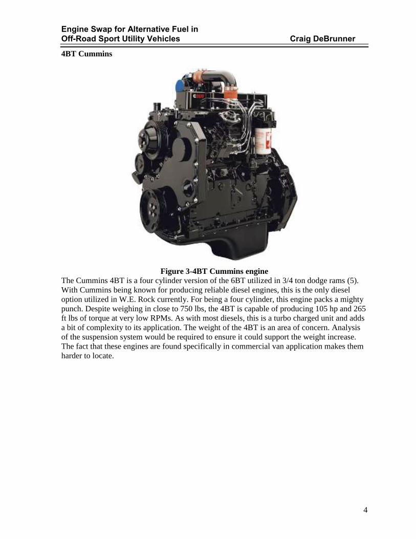
Figure 3-4BT Cummins engine
The Cummins 4BT is a four cylinder version of the 6BT utilized in 3/4 ton dodge rams (5).
With Cummins being known for producing reliable diesel engines, this is the only diesel
option utilized in W.E. Rock currently. For being a four cylinder, this engine packs a mighty
punch. Despite weighing in close to 750 lbs, the 4BT is capable of producing 105 hp and 265
ft lbs of torque at very low RPMs. As with most diesels, this is a turbo charged unit and adds
a bit of complexity to its application. The weight of the 4BT is an area of concern. Analysis
of the suspension system would be required to ensure it could support the weight increase.
The fact that these engines are found specifically in commercial van application makes them
harder to locate.

Engine Swap for Alternative Fuel in Off-Road Sport Utility Vehicles Craig DeBrunner
5
Chevy 4.3
Figure 4-Chevy 4.3L engine
The Chevy 4.3 has been used in this application for its lower peak RPMs for both horse
power and torque (6). The V-6 orientation of the engine makes it a friendly application for
the Jeep's engine bay. With horsepower of the 4300 LB4 configuration well over 275 hp and
torque around 350 ft lbs, this engine is a good fit for a rock crawling Jeep. The downside to
this engine is in the throttle body injection system. Not having the experience to
appropriately fix any injection malfunction coupled with the inability to modify this engine
to an alternate fuel prohibits the use of this engine.

Engine Swap for Alternative Fuel in Off-Road Sport Utility Vehicles Craig DeBrunner
6
Chevy LS1
Figure 5-Chevy LS1 engine
The compactness and light weight of the Chevy LS1 engine make this engine desirable.
Given the aluminum block, the engine weight is very low but the aluminum cannot stand up
to higher core temperatures that any engine produces. (7) The LS1 does produce a whopping
350 Hp and 365 ft lb for torque, but at what cost? Being the premiere engine for Chevy,
obviously its sole application was originally the 1998 corvette. With the aforementioned
application and its prestige also comes a very high engine cost. Trying to stay on a budget
places this engine out-side of the realm of possibilities.

Engine Swap for Alternative Fuel in Off-Road Sport Utility Vehicles Craig DeBrunner
7
Isuzu 4BD2TC
Figure 6-Isuzu 4BD2T Engine
A second diesel engine to be considered for this project is the Isuzu 4BD2TC inline 4
cylinder engine. This engine was first used in 1992 in the Isuzu NPR mid-sized box truck,
but its predecessor the lower powered 4BD1TC was in use as early as 1986 (8). Both engines
used the same major components. The only real difference was the indirect injection method.
The 4BD2TC has a displacement of 3.9L and is capable of producing 135 horsepower and
239 foot pounds of torque.
Engine Swap for Alternative Fuel in Off-Road Sport Utility Vehicles Craig DeBrunner
8
CUSTOMER FEEDBACK AND OBJECTIVES
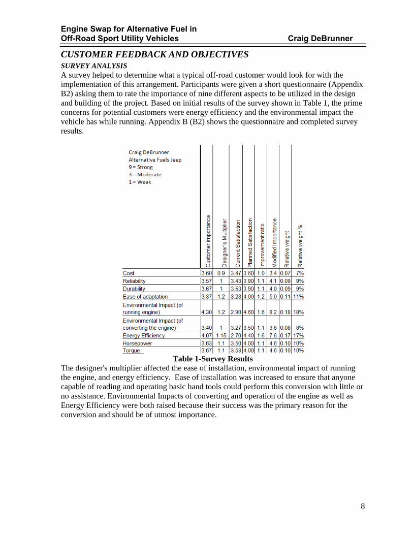
SURVEY ANALYSIS A survey helped to determine what a typical off-road customer would look for with the
implementation of this arrangement. Participants were given a short questionnaire (Appendix
B2) asking them to rate the importance of nine different aspects to be utilized in the design
and building of the project. Based on initial results of the survey shown in Table 1, the prime
concerns for potential customers were energy efficiency and the environmental impact the
vehicle has while running. Appendix B (B2) shows the questionnaire and completed survey
results.
Table 1-Survey Results
The designer's multiplier affected the ease of installation, environmental impact of running
the engine, and energy efficiency. Ease of installation was increased to ensure that anyone
capable of reading and operating basic hand tools could perform this conversion with little or
no assistance. Environmental Impacts of converting and operation of the engine as well as
Energy Efficiency were both raised because their success was the primary reason for the
conversion and should be of utmost importance.

Engine Swap for Alternative Fuel in Off-Road Sport Utility Vehicles Craig DeBrunner
9
PROJECT FEATURES AND OBJECTIVES Below is the list of objectives agreed upon by the engineering student and advisor for the
implementation of an alternative fuel in off-road vehicles. Objectives focus primarily on the
fuel conversion and secondarily on the competition rules for W.E. Rock. This conversion is
being evaluated with using only the Isuzu 4BD2T Engine and the Borg-Warner T-5 manual
transmission.
1. Environmental Impacts (18%)
a. convert to a 10% lower sulfur emissions fuel system on alternative fuel
b. convert to a carbon neutral (+/- 5%) fuel system on alternative fuel
c. reduction of greenhouse gas emission over the life of the vehicle
2. Energy Efficiency (17%)
a. 10% increase in MPG then EPA values of the Jeep CJ 4.2 on unleaded gasoline.
3. Ease of Adaptation (11%)
a. no custom tools required
b. step by step guide for installation including visual aids
c. once all components are available adaptation should take no more than 120 hours
4. Horsepower/ Torque (10%)
a. dyno testing with existing system as compared to the modified system
b. utilize components to produce horsepower and torque values equal to or higher
than published values for the 4.2 inline 6 jeep engine
5. Reliability (9%)
a. Road testing as follows:
i. 150 miles on highway terrain
ii. 100 miles on urban terrain
b. W.E. Rock Competition participation
6. Durability (9%)
a. drive train system should last 10,000 miles before any maintenance
7. Price: (7%)
a. full conversion shall cost less than $10000
8. Safety (as per competition rules)
a. undercarriage protection of fuel conversion system
i. fuel lines/wires are not easily snagged on austere terrain
b. 6 point roll cage to be added
c. fire extinguishers to be mounted on roll cage behind front seats

Engine Swap for Alternative Fuel in Off-Road Sport Utility Vehicles Craig DeBrunner
10
ENGINEERING CHARACTERISTICS Ten various engineering characteristics were utilized to help meet customer requirements as
based on the Survey. These characteristics along with the engineer's design factor can be
seen in Appendix C.
Table 2-Engineering Characteristics
The ability to use alternative fuels was the highest characteristic to be evaluated. An engine
that can only run on a single fuel regardless of any modifications made does not fit the design
requirements of this conversion. Component selection helped to determine the ease of
adaptation as well as reliability/ durability of the vehicle after fuel conversion. The strength
of materials chosen help to ensure that any adapter plates and required hardware can
withstand the forces being exerted upon them. In this specific application the engine
horsepower and torque outputs are required to be approximately equal to or greater than
those of the engine that is being replaced to ensure original performance can be maintained
or improved upon after the conversion has taken place. Minimum number of pieces to adapt,
"Bolt on" application, installation manual and use of standard parts help to eliminate excess
costs and reduce the need for special skills or tools. Appendix C contains a full
comprehensive quality function diagram for any further information.

Engine Swap for Alternative Fuel in Off-Road Sport Utility Vehicles Craig DeBrunner
11
ENGINE SELETCTION Ideally, the engineer would have preferred the Cummins 4BT. However in the search for an
engine within budget, the Isuzu 4BD2T was identified. The Isuzu engine was much more
cost effective to purchase for this application. Upon further research, the power curves
comparing the 4BT and 4BD2T (seen below in Table 3) were located online at the FD power
webpage via the Diesel-Engine magazine (9). The higher operating range of the Isuzu was
highly desirable. This operating rage allows for higher available horsepower. Unfortunately,
the 4BD2T is not capable of the higher peak torque value the 4BT produces, but it has a more
consistent output of the 255 foot pounds of torque. This is considerably higher than the
standard Jeep 258 values
Table 3-Power Curves

Engine Swap for Alternative Fuel in Off-Road Sport Utility Vehicles Craig DeBrunner
12
COMPONENT DESIGN AND MODELING Due to the nature of the project and occurrences discussed later in the report, the main
concept was determined early in the fall. The concept could not be dimensioned until other
pieces had been fabricated and in place. Measuring devices large enough and complex
enough were not available to allow design and manufacture of all pieces simultaneously.
SPECIALTY COMPONENTS As with any non-original engine conversion, special components are required to make the
conversion successful. This conversion was no different. Custom parts were made from a
number of different sources. General Tool Company, the machine shop at the University of
Cincinnati, and the backyard garage were utilized. These parts included: an adapter plate to
transmit power from the engine to the transmission; an alignment bearing to ensure crank
shaft output and transmission input are co-linear: a custom bell housing to shield the
aforementioned pieces and support the engine and transmission; mounting brackets for the
engine; and a few off the shelf components mentioned later in this report.

Engine Swap for Alternative Fuel in Off-Road Sport Utility Vehicles Craig DeBrunner
13
ADAPTER PLATE As the engine transmits the load through the crank shaft and flywheel, the clutch plate
assembly transfers this load to the transmission. Trying to reuse as much stock equipment
with minimal modifications necessitated the use of a flywheel adapter plate. The plate would
mount to the stock engine flywheel and reduce down to the stock Jeep clutch plate assembly.
The largest driving factor in the design of this piece was preventing break though at the
clutch mounting locations, this determined the plate’s thickness. Accounting for ¾” of bolt
thread engagement and adding the extra depth required to clear the threads put the required
thickness over 1” thick. This configuration would allow a bolt on application that did not
require any outside services if sold to other customers.
A computer aided drafting model of the adapter plate is shown in Figure 9 below, technical
drawings can be seen in Appendix G.
Figure 7- Flywheel Adapter

Engine Swap for Alternative Fuel in Off-Road Sport Utility Vehicles Craig DeBrunner
14
PILOT BEARING ADAPTER The adapter plate is not accounted for on the length of the transmission input shaft. This
creates an undesired space between the pinion bearing and the crank shaft. In order to remedy
this, an alignment bearing was required to ensure proper alignment of the crank shaft and
transmission input shaft. The original carrier bearing was produced at General Tool
Company to be utilized with the original bell housings on the engine and transmission. As
noted later, this bearing was required to be redesigned as the project developed and was
machined the second time in the Victory Parkway machine shop. The final Alignment
Bearing model can be seen in Figure 10 below and technical drawings can be seen in
Appendix G.
Figure 8-Alignment Bearing

Engine Swap for Alternative Fuel in Off-Road Sport Utility Vehicles Craig DeBrunner
15
BELL HOUSING When initially beginning the project, the assumption was made that the original Jeep
transmission and Isuzu engine bell housings would match up with spacing needed to allow
for the adapter plate. This was not the case. With the bell housings flush with each other
there was a gap of over four inches between the flywheel and clutch plate. To have an
adapter plate able to accommodate this spacing would create a large amount of rotating mass
along the drivetrain. This mass was deemed unacceptable and a potential safety risk. In order
to address this risk, a custom bell housing was required.. When designing the bell housing,
limitations of the bolting pattern were based upon the existing components. The engine side
of the bell housing is held in place by 11 3/8-16 bolts and the transmission side is held on by
only 4 of the 3/8-16 bolts. With the transmission only being held by 4 bolts, it is the obvious
weak point in the design. These bolts are subject to shear stress as the engine and
transmission assembly are lifted into position, as well as an axial tensile stress when in
position.
By using the following formulas for area and shear stress, the individual bolt loading can be
achieved.
𝑨𝒓𝒆𝒂 = 𝝅𝒓𝟐 𝝈 𝒔𝒉𝒆𝒂𝒓 =𝑭𝒐𝒓𝒄𝒆
𝑨𝒓𝒆𝒂 (1)
These bolts are subject to 2263.5 psi of sheer stress individually. With the grade 8 3/8-16 bolt
being capable of withstanding 90,000 psi, the four bolts holding the bell housing in place on
the transmission side are well within limits.

Engine Swap for Alternative Fuel in Off-Road Sport Utility Vehicles Craig DeBrunner
16
When looking at the axial tensile loading on these bolts the calculations were completed in
an Excel spreadsheet and used to determine thread engagement and the force required for
these threads to fail. These values were then compared to the load rating from the
manufacturer to establish the factor of safety. The screenshot below, Table 5, shows that the
bolt threads would fail first in tension with a factor of safety of 11.62.
Table 4-Screw Thread Loading
A solid model of the bell housing is shown below in Figure 11 with technical drawings
available in Appendix G.
Figure 9-Solid Model of Bell housing
Engine Swap for Alternative Fuel in Off-Road Sport Utility Vehicles Craig DeBrunner
17
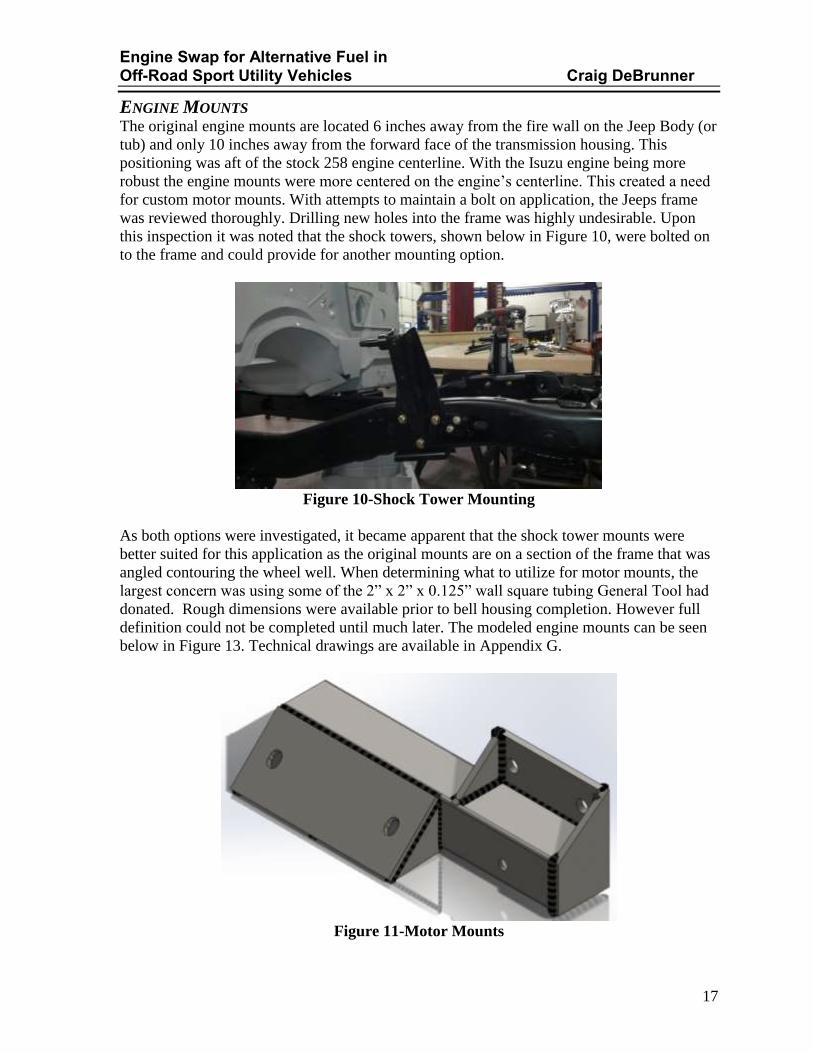
ENGINE MOUNTS The original engine mounts are located 6 inches away from the fire wall on the Jeep Body (or
tub) and only 10 inches away from the forward face of the transmission housing. This
positioning was aft of the stock 258 engine centerline. With the Isuzu engine being more
robust the engine mounts were more centered on the engine’s centerline. This created a need
for custom motor mounts. With attempts to maintain a bolt on application, the Jeeps frame
was reviewed thoroughly. Drilling new holes into the frame was highly undesirable. Upon
this inspection it was noted that the shock towers, shown below in Figure 10, were bolted on
to the frame and could provide for another mounting option.
Figure 10-Shock Tower Mounting
As both options were investigated, it became apparent that the shock tower mounts were
better suited for this application as the original mounts are on a section of the frame that was
angled contouring the wheel well. When determining what to utilize for motor mounts, the
largest concern was using some of the 2” x 2” x 0.125” wall square tubing General Tool had
donated. Rough dimensions were available prior to bell housing completion. However full
definition could not be completed until much later. The modeled engine mounts can be seen
below in Figure 13. Technical drawings are available in Appendix G.
Figure 11-Motor Mounts

Engine Swap for Alternative Fuel in Off-Road Sport Utility Vehicles Craig DeBrunner
18
ROLL CAGE When designing the roll cage, many factors were considered in the implementation of the
cage. Most cages are developed to be welded directly to the floor pans of a Jeep. Not only
does this produce a risk as the floor pan is constructed of 11guage sheet metal and cannot
withstand the stresses incurred during the event of a roll over, but also becomes an
impedance in the drivers functionality and comfort. As can be seen in Figure 14 below
traditional cages do not allow proper access to the emergency brake or the clutch pedal.
Figure 12-Traditional Roll Cage A
If those areas are accounted for and corrected, this interferes with the door opening and the
ability for driver or passenger to enter the vehicle. This can be seen in Figure 15 below.
Figure 13-Traditional Roll Cage B

Engine Swap for Alternative Fuel in Off-Road Sport Utility Vehicles Craig DeBrunner
19
As the engineer comes from a larger built ancestral line maximum accessibility and comfort
were essential for proper design. While doing research on the engine, a forum was found
where a Jeep YJ project was underway. In the YJ project the poster had developed a method
to rebuild the entire dash and redirect the stresses farther forward in the floorboards. This
directly appealed to the build requirements to retain a structural 6 point roll cage while
increasing comfort and retaining pedal interface. As engineering began to review the details
of the YJ build some inconsistencies were found in relation to standard guidelines of the
W.E. Rock competition. The largest component retained from the YJ was the ability to
transfer the stresses of a roll over through the dash and down along a station placed along the
A-pillar of the Jeep Body.
When reviewing the A-pillar of the CJ and measuring it up to the current structural metal that
formed the A-pillar, it was found that the 2” square tubing fit snuggly in this area, shown in
Figure 16 below. This area allowed the A-pillar to be reinforced to assist in the roll cage
bracing and keep the two forward points of the cage from interfering with the driver or
passenger foot room. The trouble then became how to distribute these stresses and bypass the
floor pan.
Figure 14-CJ-7 A-Pillar
Engine Swap for Alternative Fuel in Off-Road Sport Utility Vehicles Craig DeBrunner
20
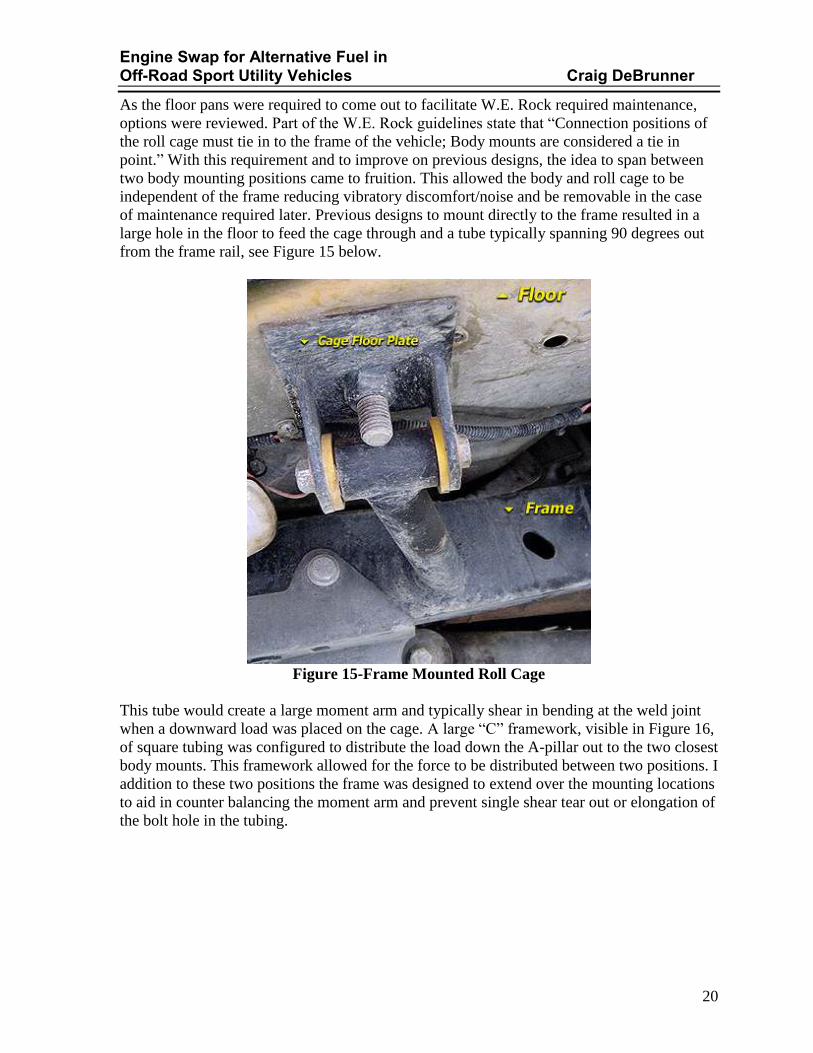
As the floor pans were required to come out to facilitate W.E. Rock required maintenance,
options were reviewed. Part of the W.E. Rock guidelines state that “Connection positions of
the roll cage must tie in to the frame of the vehicle; Body mounts are considered a tie in
point.” With this requirement and to improve on previous designs, the idea to span between
two body mounting positions came to fruition. This allowed the body and roll cage to be
independent of the frame reducing vibratory discomfort/noise and be removable in the case
of maintenance required later. Previous designs to mount directly to the frame resulted in a
large hole in the floor to feed the cage through and a tube typically spanning 90 degrees out
from the frame rail, see Figure 15 below.
Figure 15-Frame Mounted Roll Cage
This tube would create a large moment arm and typically shear in bending at the weld joint
when a downward load was placed on the cage. A large “C” framework, visible in Figure 16,
of square tubing was configured to distribute the load down the A-pillar out to the two closest
body mounts. This framework allowed for the force to be distributed between two positions. I
addition to these two positions the frame was designed to extend over the mounting locations
to aid in counter balancing the moment arm and prevent single shear tear out or elongation of
the bolt hole in the tubing.

Engine Swap for Alternative Fuel in Off-Road Sport Utility Vehicles Craig DeBrunner
21
Figure 16-MET5091-RCB-DR
Moving back to the top of the cage, a means to transmit the loading through the dash was
required. The YJ project managed this feat by building a custom dash plate allowing more
access above the driver’s legs and behind the dash to aid in bracing. While the engineer liked
this idea, it did not retain the stock appearance of the CJ and was dismissed as an option. A
means to bolt onto the original dash and transfer energy into a right angle was required. This
right angle transfer can be seen in Figure 19, with the entire cage assembly visible in Figure
20 both of which are on the following page.

Engine Swap for Alternative Fuel in Off-Road Sport Utility Vehicles Craig DeBrunner
22
Figure 17- MET-5091-RC
Figure 18- MET-5091-RC-Full

Engine Swap for Alternative Fuel in Off-Road Sport Utility Vehicles Craig DeBrunner
23
OFF THE SHELF COMPONENTS
FORD TAURUS COOLING FAN With the oversized engine and intercooler addition, a larger cooling capacity was required.
With the size limitations of the engine bay, utilizing the Isuzu cooling system was not
possible. The clutch driven fan on the engine was far too large to be accommodated without
hitting either the frame or the front axle. Since the stock Jeep radiator was to be used, the
only option was to increase the air flow through the radiator. This was obtained by using a
common upgrade to the Jeep with an electrically operated dual speed cooling fan found in an
early 3.8 liter Ford Taurus. This fan assembly is shown below.
Figure 19-Taurus Fan
HYDRAULIC CLUTCH As the final details to the engine placement were determined, it was discovered that the stock
mechanical clutch linkage would interfere not only with the starter but potentially the exhaust
system as well. Upon further investigation, it was determined that not all of the Jeep CJ’s had
a mechanical clutch linkage, and that in fact some had hydraulic clutch systems. This system
was implemented to aid in reducing the clutter of the driver’s side engine bay.

Engine Swap for Alternative Fuel in Off-Road Sport Utility Vehicles Craig DeBrunner
24
ACCESSORY DRIVE SYSTEM Over all, the accessory drive system was self-contained within the engine and very few
modifications were required. The first modification was to allow the two different engine
coolant systems to be interactive with each other. In order to complete this, the hoses
between the water pump and radiator required adapter fittings. The A/C compressor did not
come with the engine and even after looking at the location of the compressor mounting
hardware, it was determined that the system would not have fit in its original position. If
retained, the compressor would interfere with the steering assembly as well as the driver’s
side frame rail. A/C system restoration is being further investigated for future
implementation, but will not be discussed in the work scope of this project The last minor
delay was in the fact that the power steering system required a remote reservoir and
specialized fittings to complete the system as opposed to the all-in-one reservoir and pump
assembly of the original Jeep engine. An overhead view of the final engine bay configuration
is shown below in Figure 17.
Figure 20-Engine Overhead View

Engine Swap for Alternative Fuel in Off-Road Sport Utility Vehicles Craig DeBrunner
25
ELECTRICAL The last quest to conquer was integrating the engines electrical system to the Jeep’s main
wiring harness. Diesel engines are more extensive in their start up sequence, but once started
require little to no electricity to operate. The main power draw to operate the engine is the
fuel pump. With the Bosch mechanical fuel pump, once the Isuzu engine is started, electricity
is only needed to power lights and indicators. The Isuzu engine requires two 12v 750 cold
cranking amp batteries to begin the sequence. Once the key is turned to the run position,
power is supplied to the chassis. The current is routed to the starter in order to energize the
starter motor. Once the key is in the run position, a button is required to be pressed to
energize the glow plugs. The glow plugs assist in the first few moments of engine firing by
aiding in the combustion of gas vapors. While the button is depressed, the operator is
required to visualize a dash mounted ammeter. Once the amps drop from the initial reading
(typically 30 Amps) to the stabilized current (typically 22 Amps), the glow plugs are primed
and ready to assist in engine combustion. Once the amperage drop occurs, the key may be
rotated to start. Once in start position, current is supplied to the starter relay, activating the
starter solenoid. This solenoid engages the flywheel and begins the firing sequence. On the
Isuzu motor, most of this is completed by a small computer; however, the engine wiring
harness was another item missing from the engine when purchased and was required to be
made from scratch. A basic wiring schematic can be seen below in Figure 21.
Figure 21-Wiring Schematic

Engine Swap for Alternative Fuel in Off-Road Sport Utility Vehicles Craig DeBrunner
26
LOADING CONDITIONS
SAFETY FACTOR Due to the nature of the project multiple areas were accessed for factors of safety. The
primary focus is on the drive train, secondly the Roll cage, and thirdly the engine motor
mounts
TRANSMISSION LOADING According to Bruce Couture’s Modern Driveline website, the T-5 transmission is rated for a
max of 230 foot pounds of torque (9). Typical transmissions see a steady torsional load
concentration on the shafts due to the steady increase of the engine revving up. In the text Applied Strength of Materials by Robert Mott, table 4.1 suggests that these shafts have a safety
rating of 2. With the 4BD2T engine potentially producing 255 ft lbs of torque it creates an area
of concern. Comparing the published values for the engine with the transmission, and using the
Equation 1 below we can see that the safety factor within the shafts is slightly lower than 2 at a
value of 1.8. This small value change is assumed not to create a failure scenario; further,
conformation will reside with-in the actual engine torque output when placed on a dynometer.

Engine Swap for Alternative Fuel in Off-Road Sport Utility Vehicles Craig DeBrunner
27
ROLL CAGE LOADING The secondary focus is on the safety requirements for competition purposes. The largest and most
critical of these requirements is the design and fabrication of a six point roll cage in the event that
the Jeep should capsize. For these purposes Applied Strength of Materials (11) typically suggests
a safety factor of 12 due to the impact nature of a roll over. However, the fact that the body,
frame and drive train are all independently separated by bushings allows for this factor to be
lower. After review of the Finite Element Analysis (F.E.A.) performed on the main members of
the cage, a factor of safety of six was revealed. The engineer felt that this factor of safety was
sufficient in a rollover condition as they would be the primary driver.
By creating the right angle load transmission, this created a shear stress on the bolts used to
mount the two sides of the dash together. Going back to Equation 1, the loading on these
bolts in shear can be utilized to determine proper bolt diameter. These calculations are visible
below in Equation 3.

Engine Swap for Alternative Fuel in Off-Road Sport Utility Vehicles Craig DeBrunner
28
ENGINE MOUNTING When comparing the original 258 engine and the new 4BD2T engine, it is noticeable that the
original motor mounts are further aft along the frame rail. With the break in the frame
directly under the 4BD engine and desiring to limit welding, a blot on application was
reviewed. When removing the old motor mounts and shock towers, it was discovered that a
bolt on motor mount to the original shock tower frame mounts would be ideal. Shown below
in Figure 22 is the F.E.A. of the motor mounts. The purple arrows represent the weight of the
engine and the green arrows indicate the holes that were the fixed locations, This shows that
with the static load of the engine the mount has a factor of safety of three.
Figure 22-Motor Mount Static F.E.A.

Engine Swap for Alternative Fuel in Off-Road Sport Utility Vehicles Craig DeBrunner
29
Undoubtedly, the engine will also receive dynamic loading from the weight of the engine and
the road interface. Irregularities in the road interface would cause jarring on the mounts.
Those stresses would be concentrated in two locations. The first location is where the bolts
pass through the plates. At these locations the bolts would see an impact sheer stress. The
calculations for those stresses can be seen in Appendix H. The calculations show that even
with neglecting the friction forces due to torqueing the bolts down the worst stresses are seen
on the upper two bolts. These locations require a minimum 0.3622 in diameter Grade 8 bolt,
as the frame was already outfitted with 3/8” bolts in these mounting locations further frame
modifications were not necessary.
The second area is the location along the structural tubing between the two anchor pads. In
order to verify this area of concern, another F.E.A. was completed using an impact force of
the engine weight falling twelve inches. The F.E.A. determined that in an impact scenario the
motor mounts would have a factor of safety of 9.
Figure 23-Motor Mont Impact F.E.A.
Engine Swap for Alternative Fuel in Off-Road Sport Utility Vehicles Craig DeBrunner
30
FABRICATION
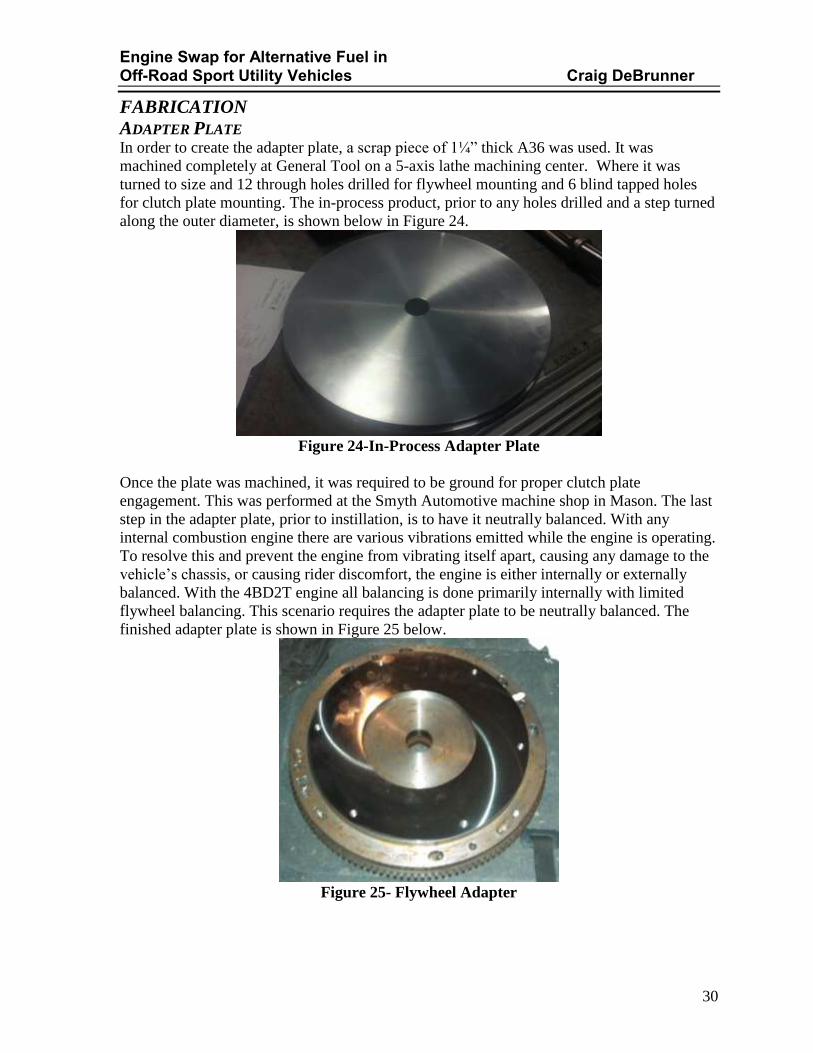
ADAPTER PLATE In order to create the adapter plate, a scrap piece of 1¼” thick A36 was used. It was
machined completely at General Tool on a 5-axis lathe machining center. Where it was
turned to size and 12 through holes drilled for flywheel mounting and 6 blind tapped holes
for clutch plate mounting. The in-process product, prior to any holes drilled and a step turned
along the outer diameter, is shown below in Figure 24.
Figure 24-In-Process Adapter Plate
Once the plate was machined, it was required to be ground for proper clutch plate
engagement. This was performed at the Smyth Automotive machine shop in Mason. The last
step in the adapter plate, prior to instillation, is to have it neutrally balanced. With any
internal combustion engine there are various vibrations emitted while the engine is operating.
To resolve this and prevent the engine from vibrating itself apart, causing any damage to the
vehicle’s chassis, or causing rider discomfort, the engine is either internally or externally
balanced. With the 4BD2T engine all balancing is done primarily internally with limited
flywheel balancing. This scenario requires the adapter plate to be neutrally balanced. The
finished adapter plate is shown in Figure 25 below.
Figure 25- Flywheel Adapter

Engine Swap for Alternative Fuel in Off-Road Sport Utility Vehicles Craig DeBrunner
31
PILOT BEARING ADAPTER The original carrier bearing was produced, on a manual lathe, at General Tool Company to
be utilized with the original bell housings on the engine and transmission. This bearing was
required to be redesigned as the project developed and was machined the second time in the
Victory Parkway machine shop. The final Alignment Bearing can be seen in the Figures 26
& 27 below.
Figure 26-Alignment Bearing without Pilot Bearing
Figure 27-Alignment Bearing with Pilot Bearing inserted

Engine Swap for Alternative Fuel in Off-Road Sport Utility Vehicles Craig DeBrunner
32
BELL HOUSING The bell housing was constructed from a weldment of ASTM A36 ¼” plate stock. Rough
pieces were cut by hand from material donated by General Tool with an oxy-acetylene torch.
Once the pieces were roughed out, two pieces were placed on the manual lathe to have the
edges cleaned up. The third piece was required to be rolled into a conical shape to facilitate
the rounded walls of the bell housing. The excess material used to roll the walls was then
trimmed off. With the excess material gone, the cone could then be welded together to form a
ring. With the cone, engine mounting and transmission mounting plates taken to rough
dimensions, the cone was welded to the transmission mounting plate. This assembly was
taken to a Bridgeport and the center transmission snap ring was milled to final size, then the
mounting bolting pattern was drilled and tapped in place. This aft half of the custom bell
housing was then taken to the VP campus to be machined to completion. The cone was
mounted onto a Cincinnati Mill rotary table. The rotary table allowed for the part to be
evenly machined to the finished height along the upper lip that would become the engine
mounting. Once complete the engine mounting flange was welded in place on the cone. At
this point the engine bolting pattern was still a bit of a mystery and needed further review to
ensure correct degrees of offset. Once this was determined, the holes were drilled oversized
through the engine mounting plate. With these holes drilled oversized it allowed for the bell
housings to be bolted together and have lugs welded on the engine mounting plate to ensure
any excess torsional stress unaccounted for would not cause failure of the mounting plate.
Even after all this, the bell housing was not complete. In order for the clutch assembly to
function properly, there is a mechanical linkage that must pass through the bell housing wall;
a window was required to be cut out to allow the throw out fork to engage and disengage the
pressure plate. This window was cut after the housing was mounted to the transmission with
a handheld right angle grinder to ensure proper clocking and size. Seen in Figure 28 below is
the transmission with the bell housing mounted and throw out fork in place.
Figure 28-Transmission and Bell housing

Engine Swap for Alternative Fuel in Off-Road Sport Utility Vehicles Craig DeBrunner
33
ENGINE MOUNTS The motor mounts were the last custom pieces required to be manufactured. The basic
concept was fully defined early in the design process. However, the final configuration was
required to be modular in order to ensure fit, form, and function. This process began with a
15” length of square tubing and a plate of ¼” ASTM A36 material. The A36 plate was drilled
to match the bolting pattern of the shock towers. Once bolted to the inboard side of the frame
rails, the square tube was located vertically along the plate to ensure proper engine mount
engagement along the forward/aft horizontal axis. After this location was determined the
plate and tube were welded together. After the tube was stable, the angled pad at the end of
the tube allowing engine mounting was welded in place. Upon further review, it was noted
that if manufactured to completion, the motor mounting holes would in fact pierce the corner
of the tubing at a 45 degree angle. Engineering did not feel that was a suitable option and
would compromise the integrity of the member. Stepping back and looking at the situation
allowed the engineer to see that the engine was not sitting at the required 3 degree downward
slope. After placing shims to account for the engine angle, enough offset was obtained to
avert compromising the tubing. These shims were then welded in place and used to drill and
tap mounting positions for the engine.
The finished engine mounts can be seen below installed in their final position in Figure 15,
technical drawings are available in Appendix G.
Figure 29-Motor Mounts

Engine Swap for Alternative Fuel in Off-Road Sport Utility Vehicles Craig DeBrunner
34
ROLL CAGE Roll cage fabrication began as the Jeep was being rebuilt in the engineer’s garage. As
mentioned before, W.E. Rock competition requirements dictated that floor pans be removed
and repaired. During this time the large “C” frames were cut, drilled and welded into
position. Prior to welding the pans back in place, the decision was made to weld the tubes to
structural members of the body to add rigidity to the frames and insure maximum safety.
Once these frames were in place, floor pans were welded back in, and the body was returned
to the chassis; work was transferred to the VP campus. The first step was to translate the
models that were used into drawing files that could be utilized in the programing of the
plasma table. Once the parts were cut, trial fitting took place to ensure that the bolt hole
patterns and spacing behind the dash were correct. During these dry fits the three primary
bolt holes were found to be on location, however, slightly under sized. Machining these
pieces on the drill press to ensure bolt clearance on all holes was required. These pieces were
then taken into the welding lab to be tack welded together. Once tacked, a secondary dry fit
was completed to ensure proper production. These right angle bracing pieces, shown in
Figure 30 below, where fully welded and left to cool as the main cross member or ‘hoop’ was
modified.
Figure 30-Right Angle Brace
In any Jeep roll cage, bends are required to negotiate the geometry of the windshield and
door. Proper tooling was not available to facilitate a custom front hoop, nor was the time
available. In order to bypass these short comings and still maintain the W.E. Rock
compliance, it was determined that a spare factory roll cage could be utilized. This roll cage
was cut down and prepped as determined by the engineer for proper fitment and aesthetic
purposes. This member was then welded to the right angle bracing pieces previously
configured.

Engine Swap for Alternative Fuel in Off-Road Sport Utility Vehicles Craig DeBrunner
35
Upon cooling, the front hoop was put into place as can be seen in the figure below. The
picture allowed the manufacturing team to see an aesthetic complication to which the
passenger side of the hoop is slightly higher than intended. Repairs were required prior to the
final welding operations. Temporarily bolting the hoop to the dash allowed for the cage
mounting bolts to be match drilled through the dash. Once match drilled, the backing plate to
transmit forces down along the A-pillar was bolted in place. This backing plate was used to
aid in proper fitment of structural members that bridged between the A-pillar tubing and
itself. These parts were found to be oversized and required grinding on top of the required
weld preps to ensure proper fitment. Once tacked in place, the pillars were removed allowing
full penetration welds to be applied, making the structure rigid. After being allowed to cool
the pillars were reinstalled and welded into place along the “C” frames. Minor adjustments
were required to allow the A-pillars to be reinforced. Some door hardware was required to be
permanently mounted through/to the tubes. The emergency brake release bracket was
modified and welded on the driver’s side as well.
Figure 31-Roll Cage front
To make the cage complete, ‘spreader bars,’ bars spanning between the front hoop and the B-
pillar of the factory roll cage, were required to be welded into place. This required that the
convertible top be removed, interior cleaned out and upholstery protected from potential
sparks. The spare cage provided enough material when the C-pillar tubes were removed.
These tubes were required to be coped and prepped in order to complete the cage welding.

Engine Swap for Alternative Fuel in Off-Road Sport Utility Vehicles Craig DeBrunner
36
SCHEDULE AND BUDGET This project's schedule begins on October 14th 2012 with the proof of design and concept
sketches given to the MET advisor. Due to the nature of this project and its competition
requirements, the schedule extends out past the normal 27 weeks ending in April, to 44
weeks ending in mid to late August. The project was broken down into various phases for
completion. The phases can be seen below in Table 5 were critical in project completion:
main assemblies acquisition, design, engine parts fabrication and install, testing and fuel
conversion, engine adjustments and W.E. Rock preparation, and final document review/
summary. A full schedule break down is available for review in appendix F.
Oct Nov Dec Jan Feb Mar Apr May Jun Jul Aug
Main Assemblies Acquisition
Design
Engine Parts Fabrication and
Install
Testing and Fuel Conversion
Engine Adjustments and W.E.
Rock Preparation
Final Document Review/
Summary
Planned
Actual
Table 5-Schedule

Engine Swap for Alternative Fuel in Off-Road Sport Utility Vehicles Craig DeBrunner
37
Initial cost analysis estimated that the conversion would cost approximately $7,500
(complete breakdown of the budget is shown below in table 5 or can be viewed in Appendix
E). The bulk of this cost is in the engine as well as the required fuel conversion components.
The second largest cost is based on W.E. Rock competition requirements. Several of the parts
will have requirements to be custom made in order to provide proper installation.
Table 6-Budget
Projected Actual
Engine
Engine 2200 800
Mounting Brackets 200 50
Wiring 100 195
Hardware 50 25
Power Transfer
Bell housing Adapter 350 0
Fly Wheel 150 300
Clutch/ Pressure Plate 250 0
Throw out bearing 50 0
Throw Out Fork 25 0
Electrical
Interior Indication 50 15
Safety
6-Point Roll Cage 1000 100
Fire Extinguishers 200 40
Reference
Shop Manuals 50 60
Miscellaneous
Miscellaneous 825 1290
total 5500 2875
Category Component
Cost ($)

Engine Swap for Alternative Fuel in Off-Road Sport Utility Vehicles Craig DeBrunner
38
TESTING AND ANALYSIS Upon completion of the project, strict dynamiter testing was conducted to aid in in the final
evaluation. The modifications made during this project enabled the engine to produce 106
horsepower and 198 ft lbs of torque. Remembering that the stock 258 cubic inch Jeep engine
of this era was able to produce 112 HP and 210 ft lbs of torque. These values show that the
Diesel engine is not currently capable of producing the increased horsepower as mentioned
earlier in the report. One might ask how a larger engine, rated capable of reaching much
higher hp and torque values could perform less than adequately. In the engines current
configuration the turbo charger is only implemented on the exhaust manifold; the intake
induction system was not complete at the time of testing, leaving the engine normally
aspirated. In addition to not having full utilization of the turbo-charger these engines
,especially with the extensive miles this particular engine is known to have, are known to
have excessive blow-by internally. In order to relieve this problem a complete engine
overhaul and rebuild would be required, that amount of labor was not included with-in the
scope of this project.
Despite these challenges further testing was complete to ensure the integrity of the Jeep
platform. The first phase of testing was to test the off road handling capabilities. Full
participation of the W.E. Rock challenge was not an option this season, will be completed in
future upcoming seasons, however unofficial course completion was incorporated. During
these trials various challenges were noted. With having a non-pressurized/ liquid fuel tank
there was some fuel flow issues during the steeper inclines of the trail. That is a typical factor
in any trail rig not utilizing liquid propane as a fuel source and was deemed an acceptable
shortcoming. This same fluid loss situation was noted on the oil system as the oil system is
also non-pressurized. A common discrepancy with any trail rig is the maximum allowable
flex in the suspension when traversing large obstacles. The suspension changes made by the
engineer were primarily for ground and engine clearance with the hopes that added
suspension flex would be possible. Minimal flex was observed, adding to the complexity of
the events. The second phase of testing was to ensure urban platform capabilities. Extensive
testing was performed to determine how the engine would affect gas mileage and handling.
With the engine operating on diesel fuel average miles per gallon (MPG) were close to 23.6
during inner city driving conditions. On the highway MPGs were averaging upwards of 26
without the use of the cruise control interface. These values are well above the established
values of today’s Wrangler body style, let alone values of 1986. Engineering had concerns in
steering and handling due to the increased weight of the engine as well as any changes in the
center of gravity (CG) with respect to the suspension modifications. Off-road courses are
hard to use to judge these conditions as the topography is infinitely changing, these aspects
were reviewed only on paved road conditions. The Jeep was able to handle very well in
normal driving conditions, excessive rolling of the cabin (to identify a possible roll over
condition within the CG) was not noted. The steering system gave no indication (unusual
groaning/grinding or broken components) of excess stresses due to the added weight and
increased CG, this will be further confirmed as records of the steering components fatigue
cycles become available.

Engine Swap for Alternative Fuel in Off-Road Sport Utility Vehicles Craig DeBrunner
39
CONCLUSION As the CJ-7 is currently configured, many small modifications need to be finished for daily
driving and full WVO operation. Local forums indicate that a Jeep is a never ending project.
However, testing and analysis for project completion were attainable. At this time
engineering feels that this technology is a viable option for future production without the
WVO application. As indicated above, all major systems for the Jeep CJ-7 platform operate
within normal operating conditions. Increasing the platforms dynamic integration will
depend on modifications to be completed outside of the scope of the project. Plans to
incorporate those changes are underway and further development and testing will be
completed as funds become available and time permits to prove these theories.
It should be noted that the project originator underestimated the knowledge in different fields
required. Previous school work in the MET program and life experience were not enough.
This shows that with proper diligence, a kit of this nature would be feasible to implement by
any individual with limited mechanical knowledge.

Engine Swap for Alternative Fuel in Off-Road Sport Utility Vehicles Craig DeBrunner
40
WORKS CITED 1. Jeep. Wikipedia. [Online] [Cited: October 29, 2012.]
http://en.wikipedia.org/wiki/Jeep.
2. Jeep Engine: AMC 258 I6. jeeptech.com. [Online] [Cited: Sept 19, 2012.]
http://www.jeeptech.com/engine/amc258.html.
3. EPA. [Online] [Cited: Oct 11, 2012.]
http://www.fueleconomy.gov/feg/bymake/jeep2005.shtml.
4. Suzuki SX4 Sportback Performance Specs. Motor Trend. [Online] [Cited: Sept 14,
2012.] http://www.motortrend.com/cars/2011/suzuki/sx4_sportback/specifications/.
5. 4BT Cummins Specs. Cummins Deisel Specs. [Online] [Cited: Sept 17, 2012.]
http://www.cumminsdieselspecs.com/4bt.html.
6. Hee, Wern. Chevy 4.3L V6 Specs. eHow. [Online] [Cited: Sept 14, 2012.]
http://www.ehow.com/facts_7598343_chevy-ls1-specs.html.
7. Assar, Jkalal. Chevy LS1 Specs. eHow. [Online] [Cited: Sept 14, 2012.]
http://www.ehow.com/facts_7598343_chevy-ls1-specs.html.
8. Official 4BD1T Power/Torque Curves. 4BTswaps.com. [Online] Feburary 23, 2012.
[Cited: November 21, 2012.] http://www.4btswaps.com/forum/showthread.php?22203-
Official-4BD1T-Power-Torque-Curves..
9. Tremec T-5. Bruce Couture’s Modern Driveline. [Online] [Cited: Feburary 21, 2013.]
http://www.moderndriveline.com/Technical_Bits/tremec_t5.htm.
10. FD Power. Diesel-Engine. [Online] [Cited: November 6, 2012.] http://www.diesel-
engine.cn/ISUZU/4BD1T.htm.

Appendix A1
APPENDEX A-RESEARCH
2.0L Suzuki
Engine: 2.0L in-line four-cylinder DOHC and four valves per cylinder
Unleaded fuel
Fuel economy: EPA (08):, 23 MPG city, 30 MPG highway, 26 MPG combined and 343 mi. range
Multi-point fuel injection
13.2gallon fuel tank
Power (SAE): 148 hp @ 6,000 rpm; 140 ft lb of torque @ 4,000 rpm
Smaller engine
high MPGs
may not be able to power larger frame vehicles as effectively
higher rpm required for torque
lower rpm gap between torque and hp
Metric hardware

Appendix A2
4bt Cummins 4BT Cummins Specs
The Cummins 4bt is essentially a 5.9L 12v Cummins with 2 cylinders
removed. This 3.9L, 4 cylinder, inline diesel was commonly used in commercial van
applications. Generous amounts of torque in a small package make the 4bt common for
engine swaps in Jeeps & small trucks/SUVs.
Cummins 4BT Specifications:
Engine Name: Cummins B3.9L/4BT
Applications: Chevrolet Step Vans, Commercial applications
Configuration: Inline 4-cylinder diesel
Displacement: 3.9L, 239 cubic inches
Bore: 4.02 inches
Stroke: 4.72 inches
Compression Ratio: 17.5:1
Aspiration: Turbocharged, non-intercooled
Engine Weight: 745 - 782 lbs
Oil Capacity: 10 quarts
Horsepower: 105 hp @ 2,300 RPM *
Torque: 265 lb-ft @ 1,600 RPM *
GVWR: 16,000 lbs
*Common rating, though horsepower & torque ratings may vary by application.
Cummins 4BT Dimensions: • Length: 30.6 inches
• Width: 24.6 inches
• Height: 37.7 inches
Cummins 4BT Info:
• Essentially a 4 cylinder version of the 6BT, the 4bt Cummins shares the same pistons,
injectors, connecting rods, & valve train design as the 5.9L 12v Cummins.
• Cummins currently manufacturers the 4bt for marine, construction, agriculture, &
other off-highway applications.
• 4BT stands for 4 cylinder, B-series, Turbocharged.
Diesel (can run on alternative fuels)
Engine is very heavy would require suspension and axel upgrades
med to low MPGs
mildly hard to find for use

Appendix A3
Chevy 4.3
The 4.3-liter Vortec Chevy V6 was the first Vortec engine ever made in 1986 and was used in
GMC and Chevy trucks. The engine boasted 155 horsepower when it first appeared. The
engine is based on what General Motors calls Vortex technology. The technology produces a
vortex or mini-tornado inside the combustion chamber. The idea was to blend fuel and air
more efficiently in the chamber, producing more power. This engine is the mainstay of the
Chevy line of light trucks and vans.
The Base Engine
o Chevy gave its 4.3-liter V6 a numerical designation of "4300." This engine was built as a 90-
degree Vortec engine that displaces 4,300 cubic centimeters or 262.3 cubic inches. This
engine was based on the 350-cubic inch 5.7-liter V8 small block Chevy engine. The LB4 V6
4300 engine was used only in passenger cars, and then, in 1991, the engine expanded into
light trucks.
GMC Syclone
o In 1991, the GMC Syclone debuted with the 4300 LB4 engine. The truck boasted 280
horsepower with 350 torque at 3,600 rpm. This was the first use of multi-port fuel injection
on the 4300 engine. The LB4 was retired in 1998. In 1992 the engine cylinder block was
modified, and Chevy came out with the L35 central port-injected engine, followed by the
LF6 in 1996
The Current Engine
o In 2002, the 4300 received another facelift as GM went back to the multi-port injected engine
and introduced the LU3 and the LG3. The LU3 engine 4300 Vortec version is surviving well
in models such as the Chevy S-10 light. The current LU3/LG3 engine is rated between 180 to
200 horsepower at 4,600 rpm with 260 foot-pounds of torque at 2,800 rpm, depending on the
model driven. The engine uses a cast-iron block and heads and has a bore and stroke of 4
inches by 3.48 inches. The engine has an overhead valve configuration with two valves per
cylinder.
Lower peak RPM for torque and HP
low MPGs
v6 easier to fit into a jeep
major issues with Throttle Body injection

Appendix A4
Chevy LS1 Performance
The 5.7 liter (346 cid) LS 1 generated 350 horsepower and 365 lb.-feet of torque (the amount of force required to turn a camshaft one full rotation). It had a compression ratio of 10.5 to 1 (the maximum amount of an engine's volume compared to its minimum.
Bore and Stroke
The engine had a 3.898 inch bore and a 3.622 stroke. The bore value represents the space a piston has to enter an engine's combustion chamber, and the stroke represents the distance a piston must travel each way when entering and exiting the combustion chamber.
Design
The LS 1 had an aluminum block and aluminum heads, allowing its assembly to weigh a relatively light 107.67 pounds (48.85 kg). It had one ignition coil per cylinder, a crank-triggered optical distributor and a hydraulic roller cam. It received gas through an electronic fuel injection system, and employed a reverse-flow water cooling system.
Aluminum block
Very light weight
cannot stand up to higher core temperatures
generally found in corvettes (i.e. very pricey)
low MPGs
very high amounts of torque and horsepower

Appendix A5
Isuzu 4BD2TC
Comparable to the Cummins 4BT
lower peak torque but less of a drop at higher RPM's
higher peak hp
higher RPM range

Appendix A6
AMC 258 (stock Jeep CJ engine)
The AMC 258 was introduced in 1971 in J-series pickups and Wagoneers and in 1972 in CJs.
It continued to be used through 1990 in the Wrangler. It is basically a stroked 232 engine.
The great thing about this engine is it reliable, inexpensive, and has horse power and torque
peaks at low RPM.
The 258 inline 6 (I6) engine always came from the factory carbureted any many people
complain about the Carter BBD carburetor and the maze of emissions vacuum hoses. There
are a couple articles below that can help you sort through those hoses and tune the Carter
BBD. For a carbureted engine, the 258 with the Carter BBD performs very well off road. The
258 always came with a cast iron block and cylinder head, hydraulic lifters (with non-
adjustable rockers), and 7 main bearings.
The 258 used in '87-'90 Wrangler YJs uses a computer controlled Carter BBD. It is very
similar to the 258 used in '82-'86 CJs, but performance suffers due to emission controls.
AMC 258 I6
Bore x Stroke 3.75" x 3.90"
Displacement 258 (4.2L)
Compression Ratio 9.2:1
Horsepower (net) 112@3200
Torque (net) 210@2000
Main Bearings 7
Valve Configuration OHV
Fuel 2bbl Carter BBD
The 258 used in '82-'86 CJs used a computer controlled Carter BBD. The computer controls
mixture based on an O2 sensor and other sensors.

Appendix A7
AMC 258 I6
Bore x Stroke 3.75" x 3.90"
Displacement 258 (4.2L)
Compression Ratio 9.2:1
Horsepower (net) 115@3200
Torque (net) 210@1800
Main Bearings 7
Valve Configuration OHV
Fuel 2bbl Carter BBD
low MPGs
low rpm horsepower and torque
carbureted fuel injection
cast iron block
vacuum line issues

Appendix A8
Interview being conducted through Email with founder of Grease car vegetable fuel systems,
Mr. Justin Carven. His responses to my emails are shown in red below.
Mon, Nov 5, 2012 I have generic questions to verify that I understand how the WVO system works. I am trying to
decide between the OM617.952 and the cummins 6bt to place into a Jeep cj-7. I understand that until I make that decision I cannot pick the solenoids, however I would like to understand how the system works and what capabilities you have at your facility.
Do the solenoids merely act as a fuel valve to switch between diesel and WVO? Does the heat used to heat the oil through the tank heating coil come from hot coolant coming off of the block before going back into the radiator? How does the flat plat heat exchanger fit in, is it externally mounted to the fuel tank as a supplement to the copper/ aluminum coils? If I design a tank using a cad software package like Solidworks will you be able to view it in order to fabricate? are there any limitations to the shape of the tank (ie are all end seams required to be welded at a sharp point or do you have the ability to press features such as radii?)? is there a minimum tank size that I must adhere to? (ie 10 gallons) I intend to purchase the Grease car deluxe home filtration system to filter the grease I obtain, is there any greasecar system that removes water, or can some guidance be given? Craig DeBrunner
From: Justin Carven [[email protected]]
Sent: Tuesda y, November 06, 2012 8:30 AM
Craig-
I believe you will find the following links from our website helpful in understanding how the
system works: FAQ ANIMATION
The Greasecar system is a two tank fuel system. The vehicles existing diesel tank and
filter will supply diesel fuel to the engine at start up and shut down. After start up radiator fluid will
transfer heat from the engine to the heat exchangers in the Greasecar fuel system. These heat
exchangers will heat the vegetable oil in the fuel filter, lines and fuel tank. The heat will reduce
the viscosity of vegetable oil so that it is similar to diesel and can be injected into the engine
properly. When the vehicle is being shut down for a period long enough for the fuel to cool the
vegetable oil must be purged from the fuel system and replaced with diesel for the next start up.
Purging generally takes around 30 seconds and can be done while driving with the push of the
button on you Greasecar controls.
The flat plate heat exchanger is plumbed in series to the Greasecar coolant circuit to add
additional heat for cold weather applications. The unit is generally mounted under the hood
and the last point vegetable oil is passed through before entering the fuel selection solenoids.

Appendix A9
Solenoids are used to select between diesel and vegetable oil feed and return circuits.
Sheetmetal shearing and forming operations are sub contracted, welding and finish work/
assembly is done in house. Simple designs of custom tanks with angled corners are preferred
but curved faces can be incorporated when necessary. some examples of custom tanks can be
seen HERE. There are dimensional considerations for a tank design, primarily space
allowance for the heat exchanger assembly. When designing sheet metal assemblies in
Solidworks it is best to transfer them to drawings then fax or email.
We do not offer any filtration products that force separate water from oil. THISarticle is a
good reference to learn about collection and filtration of oil.
For what it's worth, the 4BT is probably a better option in terms of size and weight compared
to a 6BT for a Jeep project.
--
Justin Carven
Greasecar Vegetable Fuel Systems
413.534.0013
Tuesday 6 Nov 12
Mr. Carven,
I guess I had glanced over the FAQ section that I forgot what the first point said, my apologies. the animation is exactly what I was looking for, is there a way to set it so that the model does
not continuously rotate? I'd like to take a closer look at the front end view without the car outline.
So the flat plate exchanger is between the tank and the solenoids to better ensure that the oil
remains the correct temperature. Being in SW Ohio I would most likely not see the benefits of adding the flat plate, correct?
How big is the copper heat exchanger assembly? Rough dimensions will work so I may begin planning. Is there any reason I could not place the WVO tank in the engine compartment, if given the
correct space? It would reduce the required line length as well as heat loss along the fuel lines, correct?
I am glad to see that the home filtration system has the barrel warmer, I did not see that previously.
The separation manner discussed on that link was much more informative than what I was able to
find on the forums.
I've been concerned with the weight of the 6bt in the jeep, however I'm having a hard time locating a 4bt engine in this area. I'm scheduled to meet with my mechanic tomorrow to see what options I
may have with the parts I have currently for the stock engine.
I'm sorry if my previous emails were unclear and made it sound as if I were going to make my
own WVO system from scratch. I have all intentions to purchase a greasecarsystem and install into the jeep. Am I still able to get the educational discount that you previously mentioned?
Craig
Craig-

Appendix A10
I guess I had glanced over the FAQ section that I forgot what the first point said, my apologies. the animation is exactly what I was looking for, is there a way to set it so that the model does
not continuously rotate? I'd like to take a closer look at the front end view without the car outline.
There is no way to freeze the flash animation. A full set of schematics are
included with each kit, which detail the layout.
So the flat plate exchanger is between the tank and the solenoids to better ensure that the oil remains the correct temperature. Being in SW Ohio I would most likely not see the benefits of adding
the flat plate, correct?
If you will not be running the engine regularly in sub-freezing temperatures and
your engine is generating good heatyou should not need the flatplate
How big is the copper heat exchanger assembly? Rough dimensions will work so I may begin planning. Is there any reason I could not place the WVO tank in the engine compartment, if given the
correct space? It would reduce the required line length as well as heat loss along the fuel lines, correct?
We design our tanks with 18" of clearance between the inner tank wall and baffle
and the width would need to be at least 9". It is possible to build a tank to be
mounted under the hood but generally not practical due to space and capacity
limitations. There is not benefit to mounting the tank in the engine bay related to
heat loss. I am glad to see that the home filtration system has the barrel warmer, I did not see that previously.
The separation manner discussed on that link was much more informative than what I was able to
find on the forums.
I've been concerned with the weight of the 6bt in the jeep, however I'm having a hard time locating a 4bt engine in this area. I'm scheduled to meet with my mechanic tomorrow to see what options I
may have with the parts I have currently for the stock engine.
I performed a quick search and found a 4bd2t in my area out of an '93 isuzu truck, I believe this
came out of a '93 NPR. Will the 2002 isuzu NPR kit that Grease car sells work with this engine to your knowledge? If so what is the complications that make this kit a class C?
NPR engines are pretty big. Type C kits are those with limited vehicle specific
installation documentation (no photos or model specific mounting instructions). I'm sorry if my previous emails were unclear and made it sound as if I were going to make my
own WVO system from scratch. I have all intentions to purchase a greasecar system and install into the jeep. Am I still able to get the educational discount that you previously mentioned?
We offer an educational discount for complete conversion kits but not for misc.
individual items. Craig
So I need to have at least a 18" x 9" x 2" section to place the heater in. Can the pump be slid inside the coil? can I have rough dimensions for that assembly?
For conversions that require an additional fuel pump, the pump is mounted in the engine bay, not in
the tank. You are correct about those dimensions.

Appendix A11
With mounting into a jeep I'd be at a 'class c' conversion anyway correct? The instructions will not
show me where to physically attach items like the heat exchanger or solenoid valves. but it will instruct how all components are collectively assembled and where to insert the proper fittings
to implement into the current systems? The NPR is smaller then the 4BT I was going to put in the jeep.
Any kit package we supply without vehicle specific instructions is classified
as "Type C". A generic instructional manual which explains function and
placement of components related to themselves will be included along
with wiring and plumbing schematics.
Would that discount apply on the filtration system? Can you shead some light on the pros and cons
to the NPR suggested solenoid valves? The description on the website really only details the material they are made of. I'm unsure how to determine the fuel and return lines (mainly length), are those
lines able to be cut to fit or are they like hasrd lines that are in specific lengths that total 15' and require couplings? Does the on board computer not perform the same functions of the Vacuum gage?
Is there a chance I could purchase the kit and have the tank fabricated at a later time once I can
finalize the design?
If you buy a conversion kit and pump package we can offer you the 10%
discount on the entire invoice. I don't understand your question about the
valves but the primary difference is resistance at higher flows. Flow
capacity low to high: SV-100, SV-150, SV-200. Fuel lines are all cut to length
during installation, hardware and clamps to make connections are
included. The Co-Pilot does not have a vacuum gauge function. It would
be better for you to mock up your tank and order everything at once, you
will not be able to complete the installation without the tank anyway.
.3.
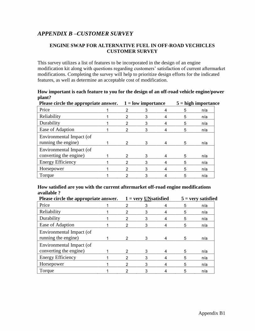
Appendix B1
APPENDIX B –CUSTOMER SURVEY
ENGINE SWAP FOR ALTERNATIVE FUEL IN OFF-ROAD VECHICLES
CUSTOMER SURVEY
This survey utilizes a list of features to be incorporated in the design of an engine
modification kit along with questions regarding customers’ satisfaction of current aftermarket
modifications. Completing the survey will help to prioritize design efforts for the indicated
features, as well as determine an acceptable cost of modification.
How important is each feature to you for the design of an off-road vehicle engine/power
plant?
Please circle the appropriate answer. 1 = low importance 5 = high importance
Price 1 2 3 4 5 n/a
Reliability 1 2 3 4 5 n/a
Durability 1 2 3 4 5 n/a
Ease of Adaption 1 2 3 4 5 n/a
Environmental Impact (of
running the engine) 1 2 3 4 5 n/a
Environmental Impact (of
converting the engine) 1 2 3 4 5 n/a
Energy Efficiency 1 2 3 4 5 n/a
Horsepower 1 2 3 4 5 n/a
Torque 1 2 3 4 5 n/a
How satisfied are you with the current aftermarket off-road engine modifications
available ?
Please circle the appropriate answer. 1 = very UNsatisfied 5 = very satisfied
Price 1 2 3 4 5 n/a
Reliability 1 2 3 4 5 n/a
Durability 1 2 3 4 5 n/a
Ease of Adaption 1 2 3 4 5 n/a
Environmental Impact (of
running the engine) 1 2 3 4 5 n/a
Environmental Impact (of
converting the engine) 1 2 3 4 5 n/a
Energy Efficiency 1 2 3 4 5 n/a
Horsepower 1 2 3 4 5 n/a
Torque 1 2 3 4 5 n/a
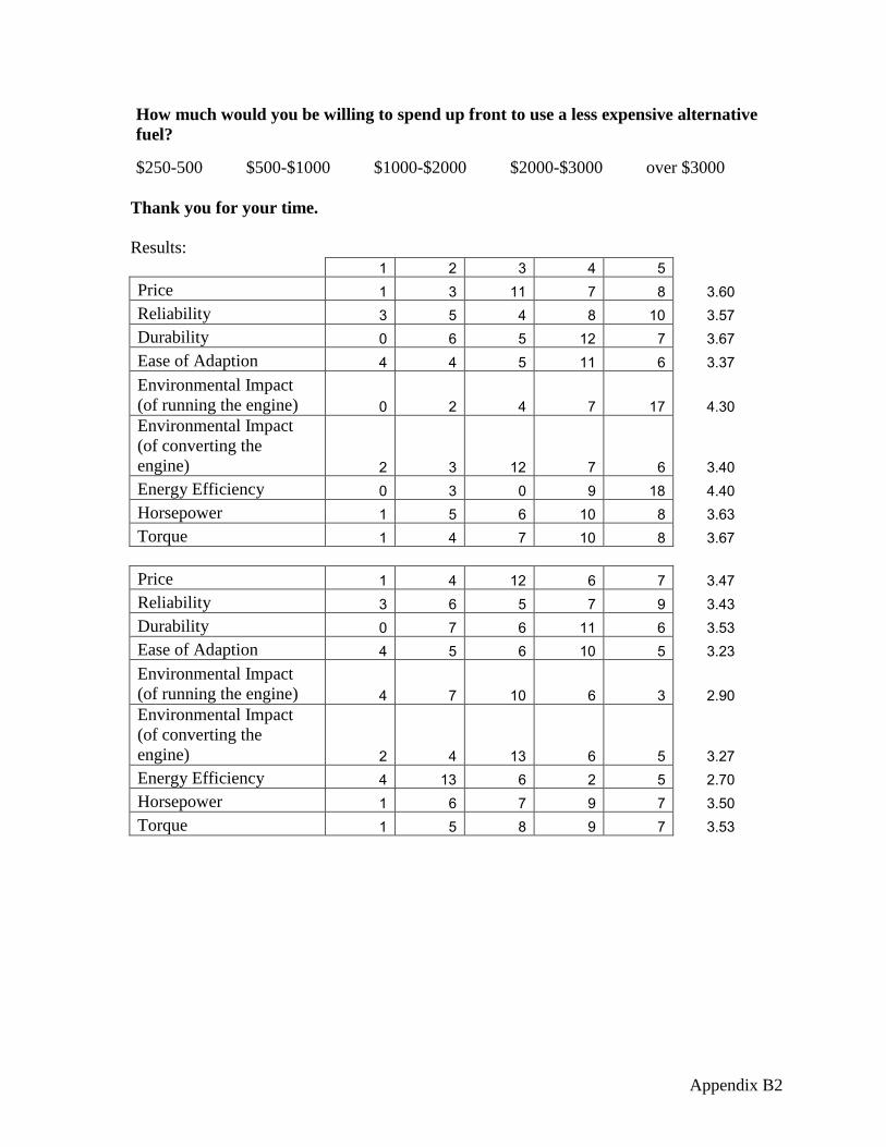
Appendix B2
How much would you be willing to spend up front to use a less expensive alternative
fuel?
$250-500 $500-$1000 $1000-$2000 $2000-$3000 over $3000
Thank you for your time.
Results:
1 2 3 4 5 Price 1 3 11 7 8 3.60
Reliability 3 5 4 8 10 3.57
Durability 0 6 5 12 7 3.67
Ease of Adaption 4 4 5 11 6 3.37
Environmental Impact
(of running the engine) 0 2 4 7 17 4.30
Environmental Impact
(of converting the
engine) 2 3 12 7 6 3.40
Energy Efficiency 0 3 0 9 18 4.40
Horsepower 1 5 6 10 8 3.63
Torque 1 4 7 10 8 3.67
Price 1 4 12 6 7 3.47
Reliability 3 6 5 7 9 3.43
Durability 0 7 6 11 6 3.53
Ease of Adaption 4 5 6 10 5 3.23
Environmental Impact
(of running the engine) 4 7 10 6 3 2.90
Environmental Impact
(of converting the
engine) 2 4 13 6 5 3.27
Energy Efficiency 4 13 6 2 5 2.70
Horsepower 1 6 7 9 7 3.50
Torque 1 5 8 9 7 3.53

Appendix C1
APPENDIX C – QFD

Appendix D1
APPENDIX D -PRODUCT OBJECTIVES Objectives
Below is a list of the objectives for the engine swap for alternative fuel in off road vehicles as
well as the way in which each measure is achieved. The indicated objectives focus primarily on
the installation of an engine and its alternative fuel system. The objectives' rankings will be based
upon feedback in the customer survey.
1. Environmental Impacts (18%)
a. convert to a 10% lower sulfur emissions fuel system on alternative fuel
b. convert to a carbon neutral (+/- 5%) fuel system on alternative fuel
2. Energy Efficiency (17%)
a. 10% increase in MPG then EPA values the Jeep Wrangler 4.0 on regular fuel.
3. Ease of Adaptation (11%)
a. no custom tools required
b. step by step guide for installation including visual aids
c. once all components are available adaptation should take no more than 120
hours
4. Horsepower/ Torque (10%)
a. dyno testing with existing system as compared to the modified system
b. utilize components to produce horsepower and torque values equal to or
higher then published values for the 4.0 inline 6 jeep engine
5. Reliability (9%)
a. Road testing as follows:
i. 150 miles on highway terrain
ii. 100 miles on urban terrain
b. W.E. Rock Competition participation
6. Durability (9%)
a. drive train system should last 10,000 miles before any maintenance
7. Price: (7%)
a. full conversion shall cost less than $10000
8. Safety (n/a)
a. undercarriage protection of fuel conversion system
i. fuel lines/wires are not easily snagged on austere terrain
b. 6 point roll cage to be added
c. fire extinguishers to be mounted on roll cage behind front seats

Appendix E1
APPENDIX E - BUDGET
Projected Actual
Engine
Engine 2200 800
Mounting Brackets 200 50
Wiring 100 195
Hardware 50 25
Power Transfer
Bell housing Adapter 350 0
Fly Wheel 150 300
Clutch/ Pressure Plate 250 0
Throw out bearing 50 0
Throw Out Fork 25 0
Electrical
Interior Indication 50 15
Safety
6-Point Roll Cage 1000 100
Fire Extinguishers 200 40
Reference
Shop Manuals 50 60
Miscellaneous
Miscellaneous 825 1290
total 5500 2875
Category Component
Cost ($)

Appendix F1
APPENDIX F - SCHEDULE

Appendix F2

Appendix G1
APPENDIX G-TECHNICAL DRAWINGS

Appendix G2

Appendix G3

Appendix G4

Appendix G5

Appendix H1
APPENDIX H-MOTOR MOUNT IMPACT CALCULATIONS

Appendix H2

Appendix H3