engine management system operations and maintenancethe engine management system (ems). it uses the...
TRANSCRIPT

MORGAN PLUS 81998 – 2004
Operations and MaintenanceEngine Management System
15 July 2005Morgan Plus 8 GEMS Version 4.702
ContentsTitle
Introduction Fuel Injection Basics Introduction to GEMS General Considerations Tools and Precautions Morgan-Specific Differences Known Failures GEMS Diagnostic Tools Engine Control Module EMS Components Diagnostics Maintenance Procedures RovacomLite Autotap OBD Generic Trouble Codes GEMS Specific Trouble Codes Copyright and Disclaimers
Page37
1117202225293746747988
100105107109

15 July 2005Morgan Plus 8 GEMS Version 4.703
Introduction
15 July 2005Morgan Plus 8 GEMS Version 4.704
Introduction This presentation covers the Lucas-SAGEM GEMS Engine Control Module
(ECM), which, together with the sensors and actuators, form the EngineManagement System (EMS). It was installed on Morgan Plus-8 models from1998 to 2004 fitted with 4.0 V-8 engines.
GEMS was introduced on chassis number R12451 with the 50D engine, and theonly main change occurred at chassis number R12511 with the change to the 87Dengine, when the “advanced evaps” fuel evaporation control system wasintroduced in order to comply with the current On-Board Diagnostic (OBD-II) NorthAmerican Specifications (NAS) certification standards.
The knock sensors were removed at the same time, and a new program used inthe ECM. These are contained in PROMs (see over) specially made for MMC,and have serial numbers 9660 for model year 2000 and 9664 for Model year 2002– other year/serials are not known.
The Lucas 10AS security system is also fitted. It is very sophisticated and canaccept multiple analogue and discrete sensor inputs, warn of catalyst overheating,as well as control alarms and interior lights – but only the engine disable (secureimmobilization) function is used in the Plus 8. It is controlled by a remote “PLIP”,and when disarmed it sends a data word to the GEMS which compares it with astored data word – if they match GEMS will allow the engine to start.

15 July 2005Morgan Plus 8 GEMS Version 4.705
CA
TM
UF
FL
ER
CA
TM
UF
FL
ER
NOT SHOWNOR HIDDENON THIS VIEW
Component Locations
EFT
IACV
TPS
ECT
MAF
CKP
FPR
IAT
IS
CMP
CPV
CVS
FTPS
HO2S
KS
KS
HO2S
PR
MRSR
PTP
FFTR

15 July 2005Morgan Plus 8 GEMS Version 4.706
Abbreviations
ProgrammableRead-Only Memory
PROM
Inlet Air Control ValveIACV
Heated O2 SensorHO2S
Fuel FilterFFTR
Fuel Pressure RegulatorFPR
Engine Management SystemEMS
Engine Fuel TemperatureEFT
Engine Coolant TemperatureECT
Engine Control ModuleECM
Canister Vent SolenoidCVS
Canister Purge ValveCPV
Camshaft Position SensorCMP
Crankshaft Position SensorCKP
California Air Resource BoardCARB
MeaningAbbreviation
Land RoverLR
Pressure Test PointPTP
Fuel Tank Pressure SensorFTPS
Throttle Position SensorTPS
Starter RelaySR
Multi-Function Relay ModuleMRM
On-Board DiagnosticMonitor
OBDM
On-Board Diagnostics IIOBD-II
Pump RelayPR
Main relayMR
Mass Air FlowMAF
Knock SensorKS
Inertia SwitchIS
Inlet Air temperatureIAT
MeaningAbbreviation

15 July 2005Morgan Plus 8 GEMS Version 4.707
Fuel Injection Basics
15 July 2005Morgan Plus 8 GEMS Version 4.708
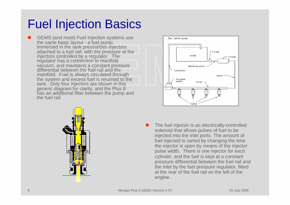
Fuel Injection Basics GEMS (and most) Fuel Injection systems use
the same basic layout - a fuel pumpimmersed in the tank pressurizes injectorsattached to a fuel rail, with the pressure at theinjectors controlled by a regulator. Theregulator has a connection to manifoldvacuum, and maintains a constant pressuredifferential between the fuel rail and themanifold. Fuel is always circulated throughthe system and excess fuel is returned to thetank. Only four injectors are shown in thisgeneric diagram for clarity, and the Plus 8has an additional filter between the pump andthe fuel rail.
The fuel injector is an electrically-controlledsolenoid that allows pulses of fuel to beinjected into the inlet ports. The amount offuel injected is varied by changing the timethe injector is open by means of the injectorpulse width. There is one injector for eachcylinder, and the fuel is kept at a constantpressure differential between the fuel rail andthe inlet by the fuel pressure regulator, fittedat the rear of the fuel rail on the left of theengine.
15 July 2005Morgan Plus 8 GEMS Version 4.709
Fuel and Ignition Control Most Fuel Injection (FI) systems use a mass air flow sensor of some type – early
ones derived the MAF from the manifold depression, but later systems measuredit directly by means of a flapper valve or, in GEMS, by the change in resistancewith mass air flow of a hot wire. Some early systems use a standard distributor tocontrol ignition, but more advanced system such as GEMS compute both fuel andignition parameters. It might be assumed that each fuel pulse would only varywith the quantity of air ingested each stroke, which is measured by MAF. In fact,the efficiency of the intake system varies with RPM and throttle opening as it isaffected by internal resonances. The FI systems store this information in an n-dimensional Fuel Map, and use this data to compute the length of the injectorpulse. This is sent to the injector in the form of an electrical pulse of variablewidth, using a technique called Pulse Width Modulation (PWM)). The latersystems use a crankshaft position sensor on the flywheel to determine firing andinjection firing position, and a camshaft position sensor to make sure that theyoccur on the correct stroke.
The later systems also use Direct Ignition, with a single or double-ended coilconnected to each cylinder or pair of cylinders. The ignition advance is computedusing a similar map to the fuel system.

15 July 2005Morgan Plus 8 GEMS Version 4.7010
Fuel and Ignition Maps This is a typical Fuel Map – it applies corrections to the measured mass air flow (or the air
flow implied by the manifold pressure in this example) caused by variations in the pumpingefficiency of the engine as the RPM changes. A similar three-dimensional map is used tocalculate ignition advance at various RPM and load values.
GEMS uses engine speed and Mass Air Flow instead of Manifold Pressure as inputs, andthe final output is injector pulse width.

15 July 2005Morgan Plus 8 GEMS Version 4.7011
Introduction to GEMS
15 July 2005Morgan Plus 8 GEMS Version 4.7012
Introduction to GEMS - 1 GEMS is an advanced digital closed-loop Sequential Fuel Injection (SFI) system
with Direct Ignition (DI), controlled by an Intel digital processor in the EngineControl Module (ECM), which together with the sensors and IACV actuator formsthe Engine Management System (EMS). It uses the ISO 9141-2 interfacestandard (which in the US is referred to as Chrysler/Import), and is in fullconformance with NAS OBD-II standards.
It can adapt to minor changes in engine characteristics, and can control theignition advance of each cylinder independently if knock is detected. There are noexternal user adjustments except for the idle air bleed bypass, which is under ablanking plug on the throttle body. It is fitted to the Plus 8 in the North AmericanSpecification (NAS) standard, with four O2 (Lambda) sensors, one in front andbehind each catalytic converter.
GEMS stores all the operational parameters including fuel and ignition maps intwo PROMS, which can be removed or changed when the ECM is opened. It alsostores adaptive and setup data (such as Manual/Auto transmission, Enginecapacity and VIN) in Erasable PROMS so that the main settings are not lost if thepower to the ECM is interrupted.
15 July 2005Morgan Plus 8 GEMS Version 4.7013
Introduction to GEMS - 2 It uses a high pressure fuel rail maintained at a constant pressure differential (35
psi) with respect to the inlet manifold, and the injectors are timed to fire on eachintake stroke. The mixture is controlled by measuring the mass air flow into theengine, applying corrections for temperature and variations in engine intakeefficiency with RPM, and then calculating the correct injector pulse width neededto achieve the desired fuel/air ratio. The oxygen content of the resultant exhaustgas is measured and corrections made to the injector pulse width – these take theform of long and short term fuel trims. The short term fuel trim varies in real timeas the engine changes operating conditions, but the long term fuel trim iscalculated as an average of the short term fuel trim value and changes veryslowly. The long term fuel trim is one of the adaptive parameters and is storedwhen the engine is shut down.
The idle speed is controlled by the Idle Air Control Valve (IACV), which uses astepper motor to open and close the idle air bleed. There is also an air bleedbypass which must be set to ensure that the IACV operates in the correct part ifits range – a dirty IACV or incorrect setting of this bypass are the most commonproblems when idle faults are encountered. GEMS determines that the throttle isclosed by comparing the voltage from the throttle position sensor with a storedvalue of the closed position, so if the stored value is incorrect GEMS will not beable to detect closed throttle or idle correctly.
15 July 2005Morgan Plus 8 GEMS Version 4.7014
Operational Modes GEMS normally operates in a closed loop mode, using the data from the heated
O2S to optimize the fuel/air mixture Under some conditions GEMS will default to open loop control; the full list of
operating modes is shown below. These can only be read by a Rovacom orsimilar diagnostic unit.
OPEN NOT YET SATISFIED CONDITIONS The engine is not running or is still too cold to use the feedback from the sensors so when there
is nothing wrong, the system is open loop CLOSED USING O2 SENSORS NORMALLY
This is the usual operating mode; the engine is operating normally with no faults detected OPEN DUE TO DRIVING CONDITIONS
The system has been using the sensors and there are no problems, but it has decided not touse them at the moment, as the feedback is not required for correction
OPEN DUE TO A DETECTED FAULT There is a fault with the sensor and the system has reverted to using the pure map without the
aid of closed loop correction CLOSED BUT AN O2 SENSOR IS FAULTY
This can only happen in vehicles fitted with two sensors per bank, or the NAS standard. Thisapplies to all Plus 8 manufactured with the Advanced Evaps system. Although the systemknows one of the sensors is faulty it can switch to using the other one to give closed loop fuelcorrection

15 July 2005Morgan Plus 8 GEMS Version 4.7015
Adaptive Parameters - 1 The adaptive parameters use a Z-transformed statistical technique to calculate
the average difference between the mapped settings in the ECM EPROMS andthe actual settings required due to minor difference in the engine build standard.Since they compute an average over time the car will have to be driven for somedistance before they converge to the correct values.
The main adaptive parameters are:
Adaptive Fuel Mass Flow Rate The Adaptive Fuel Mass Flow Rate (FMFR) is learnt by the system over a period of time and is
added to the normal fuel rate to compensate for manufacturing tolerances between fuellingcomponents
The limits are + 0.625 to -0.625, after which it will log a fault in its memory Adaptive Air Mass Flow Rate
The Adaptive Air Mass Flow Rate (AMFR) is learnt by the system over a period of time and isadded to the normal air rate to compensate for manufacturing tolerances between airflowcomponents
The limits are + 5.5 Kg/hr to -5.5 Kg/hr after which it will log a fault in memory Short Term Idle
This is the value that the GEMS uses to regulate the current idle speed to take into accountcurrent engine load, temperature, etc
Long Term Idle This is the value that the GEMS learns over a period of time to take into account manufacturers
tolerances on component which affect overall idle speed

15 July 2005Morgan Plus 8 GEMS Version 4.7016
Adaptive Parameters - 2 Closed Throttle Value
This Adaptive value is stored by the GEMS so it knows when the engine is at idle If any adjustments are made which result in the stored value being lower than the
current throttle position with the throttle properly closed poor idle characteristicsmay occur
Gems can re-learn its new value by re-setting all ECM Adaptations when it will beset to 0.85 volts – the first time the engine is started the ECM will then store thenew closed throttle value. It can also be set manually, but this is not advised.
There are number of other parameters that will be affected by the resetfunction, including the Long Term Fuel Trim, but these are of lesserimportance and rapidly adapt after a reset operation.

15 July 2005Morgan Plus 8 GEMS Version 4.7017
General Considerations

15 July 2005Morgan Plus 8 GEMS Version 4.7018
General Considerations - 1 GEMS in the Morgan Plus 8 is a well engineered system that was fitted to a
variety of Land Rover (LR) vehicles, but the most easily accessible manuals arethose of the Discovery 1 of 1998, just before LR changed to the Bosch Motronic.There are very few LR factory recalls or bulletins, and it is probable that anyreliability or performance problems are due to lack of, or poor, maintenance. Thesystem has default strategies for all sensors except two – Mass Air Flow andCrankshaft Position Sensors. Failure of either of these, or the fuel pump, will stopthe engine.
GEMS can easily be maintained by the average home mechanic, but a diagnosticcomputer is essential. There are many generic OBD-II system available fromaround $150 and they are useful for emission compliance information as well asgeneral fault diagnosis. Autotap (http://www.autotap.com/) is installed on a laptopand has real time data logging capabilities, and was used in the development ofthis presentation.
In addition, a special purpose GEMS diagnostic unit is essential for the long-termmaintenance of the system. It is required to read the GEMS-specific data notavailable through a generic OBD system, to reset the adaptive parameters, setthe idle performance, and for all security system settings. There are only threemanufacturers of these; TestBook is only available to official LR dealers, whileAutologic and Rovacom were developed for sale to independent garages.
15 July 2005Morgan Plus 8 GEMS Version 4.7019
General Considerations - 2 The cheapest of the GEMS-specific systems used to cost in excess of $10,000,
and so service of any GEMS system was impossible for the average owner untilBlackBox released the RovacomLite (http://www.rovacomlite.com/) in 2003. Withthe GEMS and Lucas 10AS modules it costs around $1000, and was also used inthe development of this presentation.
Performance PROMS are available from RPi (http://www.rpiv8.com/) and result in asignificant improvement in engine response and performance. You will need to fitknock sensors if they are not already fitted.
If it is necessary to open the ECM or change sensors take anti-static precautionsto avoid damaging the ECM or PROMS, and use surgical rubber gloves. Becareful not to contaminate connector pins - perspiration or contamination willcorrode them over time. You do not need to disconnect the battery when youremove the ECM, although it cannot hurt. If you do disconnect the battery GEMSwill have to re-learn some adaptive settings which may take up to 50 miles or so.
GEMS has settings for both manual and automatic transmissions, and 4.0 and 4.6liter engines. The automatic transmission setting can cause a reluctance for theengine to decelerate, and the wrong capacity engine setting can cause incorrectmixture at higher RPM. The settings can only be checked or changed with one ofthe special GEMS diagnostic systems.

15 July 2005Morgan Plus 8 GEMS Version 4.7020
Tools and Precautions
15 July 2005Morgan Plus 8 GEMS Version 4.7021
Tools and Precautions Tools:
The usual mix of AF and Metric wrenches and a torque wrench to fit knock sensors. A TORX 25 driver to open the ECM. An Electro-static discharge wrist strap, pad, and chip puller when changing PROMS. An OBD II diagnostic system for Chrysler/Imports (to check and clear DTCs, reset the MIL indicator,
to access freeze-frame data, and emission-related OBDMs). A Rovacom Lite diagnostic unit with a GEMS module (to check and clear DTCs, reset the MIL
indicator, access GEMS-specific data, and reset the adaptive data); and a 10AS module to interfacewith and set up the alarm system.
A Volt-Ohm Meter (VOM) A Fuel Injection Fuel Pressure Gauge.
Precautions. Depressurize fuel system before changing injectors or other work on the high pressure system (the
easiest way it to use the fuel pressure tester to depressurize it). Clean the outside of all connectors before disconnecting (glass cleaner if nothing else is available),
and protect the pins and inside of the connectors after disconnection (plastic bag and rubber band). Use ESD precautions when opening the ECM – although it is very rugged it is an expensive unit. Do not change the PROM chips unless you have access to a TestBook or Rovacom diagnostic unit –
the car will not start unless you make GEMS re-learn security.

15 July 2005Morgan Plus 8 GEMS Version 4.7022
Morgan-Specific Differences

15 July 2005Morgan Plus 8 GEMS Version 4.7023
Morgan-Specific Differences - 1 There are a number of differences in the Morgan Plus 8 GEMS installation as
compared to the standard Land Rover application from which it was derived, andthese are listed below.
Low Fuel Sensor There is a “low fuel” sensor line which stops the ECM adapting if the fuel supply is
interrupted when the tank is almost empty. It also prevents the ECM registeringmisfires from low fuel as trouble codes. Morgan use a “Fuel Level ECU” behind thedashboard to provide the correct voltage to the fuel gauge and the ECM – but somecars appear not to have this line connected. The fuel level input line should be held low(0 volts) to allow the ECM to adapt.
Automatic Transmission Inputs The EMC has a “transmission retard” input from the automatic gearbox which is used to
reduce power and so enable smoother shifts with the automatic transmission. Neitherthis or any other of the auto box inputs that could affect the ECM operation are enabled.
Rough Road Input In Land Rover applications random variations in wheel speed are detected by the
Antilock Brake System to set a “rough road” input to the ECM, which then uses thisinformation to disable the misfire error codes that would otherwise be set due to thesympathetic variations in crankshaft RPM.
Since ABS is not fitted to the Plus 8 this means that there is the possibility that themisfire monitor and “check engine” light may be set if large throttle openings are usedon really rough roads
15 July 2005Morgan Plus 8 GEMS Version 4.7024
Morgan Specific Differences - 2 OBD Diagnostic Interface
Pin 5 should be connected to Signal Ground to conform to the ISO 9141-2 standards,and the lack of this connection will cause the car to fail the emission control test. A newpin or connector will have to be obtained, and pin 5 can be connected to ground tocomply with the requirement.
Other EMC Interfaces Other interfaces that are not used include a fuel totalizer output; a heated windscreen
and air conditioning in-use inputs; engine torque output, engine speed out and throttleangle signal output to the transmission; ignition retard signal (to reduce power and easegear shifts) from the transmission; and an air conditioning condenser fan actuationoutput. The GEMS engine speed output is not used and the tachometer uses thealternator frequency as the source of engine RPM.
Since the ECM does not control the radiator fan – even though it could - this iscontrolled directly by the thermostatic switch in the base of the radiator through a relayon the right front side of the bulkhead.
Knock Sensors The knock sensors were removed from the Plus 8 at the same time that the “advanced
evaps” system was installed. The interface connectors and harness are fastened to the main harness across the front
of the engine and on to the starter motor cable on the lower right hand side. If performance PROM chips are to be fitted two LR knock sensors will be required if
they are not fitted. They are available from LR - part number ERR5594, and generallyavailable next day from LR dealers. Two small heat shields are also required, and areavailable from MMC. The heat shields are designed to be bolted to the enginemountings, and suitable holes will have to be drilled in the engine mounts and the heatshields. It is important that the sensors are tightened to the correct torque – 12 lbs/ft.

15 July 2005Morgan Plus 8 GEMS Version 4.7025
Known Failures
15 July 2005Morgan Plus 8 GEMS Version 4.7026
Known Failures - 1 As far as is known there are three types of failures that have been experienced on Morgans,
but they may be isolated instances and not cause for concern. They are mentioned asgeneral background material in case similar symptoms are experienced. The only TechnicalBulletin issued by LR is for CKP/Flywheel contact which is the first of the failures mentionedbelow.
Crankshaft Position Sensor/Flywheel Contact Symptoms - the engine momentary cuts out or misfires especially when the clutch is pressed in. If
the CKP sensor is removed it will show a bright spot where contact has occurred. Cause – momentary contact between the tip of the CKP and the flywheel reluctor rings caused by
either a loose CKP housing (it is bonded into the crankcase) or incorrect clearance being set duringengine manufacture
Solution – remove the inspection panel under the bell-housing and the CKP sensor, and check forsigns of contact on the sensor and on the reluctor rings. Check the CKP Sensor housing and ensurethat it firmly bonded to the crankcase. If it is loose, remove it, clean the two surfaces and re-bond itusing a reliable two-part epoxy. Replace the CKP sensor and set the sensor housing so that thesensor sits between the two rows of reluctor ring and enters them to a depth of 0.020. If the housingis securely bonded the problem is due to incorrect housing placement during manufacture, and thesolution will depend on the extent of the misalignment problem. It may be possible to remove thehousing, but if it is securely bonded it this may prove to be a difficult task. In this case the sensorcan be re-positioned using shims, or in an emergency the tip of the sensor can be filed to avoidcontact.
CAUTION - When re-installing the sensor make sure that the tip is not contaminated by magneticdebris, which can also cause problems.
CAUTION – The sensor is supplied with an alloy spacer. Some engines have this spacer bonded tothe housing, and care should be taken to make sure that two spacers are not inadvertently fitted.
15 July 2005Morgan Plus 8 GEMS Version 4.7027
Known Failures - 2 IACV Contamination
Symptoms - the symptoms are an unstable idle or failure of the engine to idle at all. Cause – if the car is not used regularly there have been instances of the IACV
becoming contaminated with either corrosion or dirt. Solution – remove the IACV and clean the pintle valve and throttle body housing with
carburetor cleaner. After re-assembly the Idle Setup Procedure should be carried out. CAUTION - take care not to force the stepper motor controlling the pintle valve to
change position NOTE –similar symptoms can be caused by mis-adjustment of the bleed air bypass
valve. If the symptoms persist after cleaning the valve and the Idle Setup Procedurehas not been performed it is almost certain that this is the cause.

15 July 2005Morgan Plus 8 GEMS Version 4.7028
Known Failures - 3 Fuel Pump Partial or Complete Failure
Symptoms (1) – Check engine light (MIL) during normal operation, accompanied by DTC P1176 -Maximum Positive FMFR Correction Fault.
Symptoms (2) – Intermittent or Complete failure of the fuel pump Cause (1) – the fuel pump has a canister around it with a foot valve that is designed to retain fuel
around the pump when fuel is low. Excessive silicon sealer used around the fuel pump body/O-ringinterface can be being extruded and fall into the tank where it is sucked into the valve, holding itopen and preventing free flow of fuel into the pump. This can have two effects (1) the fuel pumpoutput is reduced causing the ECM to attempt correction, and the subsequent setting of the MIL lightand P1176 or (2) overheating of the fuel pump and partial or complete failure.
Cause (2) – the fuel pump connector can be contaminated with underseal during car manufacture.The connector may then have a high resistance contact which can lead to partial or complete fuelpump failure.
Solution – replace the fuel pump, and cut off and replace the connector on the wiring harness if itshows signs of overheating.
In order to replace the pump the battery should be disconnected and the spare wheel, mountingbracket and trim plate should be removed. The fuel should be siphoned out of the tank afterremoving the hose to the fuel filler. The fuel system should be de-pressurized and the fuel pipeconnectors removed by pressing the locking tabs, and the pipes should be labeled to avoid mixingthem up. The fuel pump can be removed after removing the tank securing bolts and then undoingthe fuel pump retaining bolts, when the tank can be maneuvered to allow room for the pump to beremoved. A short fuel pump interface wiring harness is available from LR and should be spliced intothe Morgan harness with crimped splices and heat shrink tubing. Assembly is the reverse of theabove procedure.

15 July 2005Morgan Plus 8 GEMS Version 4.7029
GEMS Diagnostic Tools

15 July 2005Morgan Plus 8 GEMS Version 4.7030
GEMS Diagnostic Tools There are two main diagnostic tools required to maintain the GEMS system. LR
Dealers use TestBook or Autologic, but these cost over $10,000. Rovacom Litehas the same functionality and costs around $1000, but you will need a laptop tohost it. A typical OBD diagnostic system will cost between $50 - $350.
The data that can be accessed are: Rovacom (TestBook or Autologic)
DTCs and MIL reset GEMS-specific and other data Adaptive Reset Idle Setup Security Learn procedures Output commands (fuel pump is the only significant item)Rovacom does not allow access to OBD monitors or freeze-frame data
Generic OBD-II Diagnostic System (AutoTap, Actron, etc) DTCs and MIL reset Standard OBD mandated data and freeze-frame data OBD monitorsGeneric OBD tools do not allow access to GEMS-specific data, reset or security command options
15 July 2005Morgan Plus 8 GEMS Version 4.7031
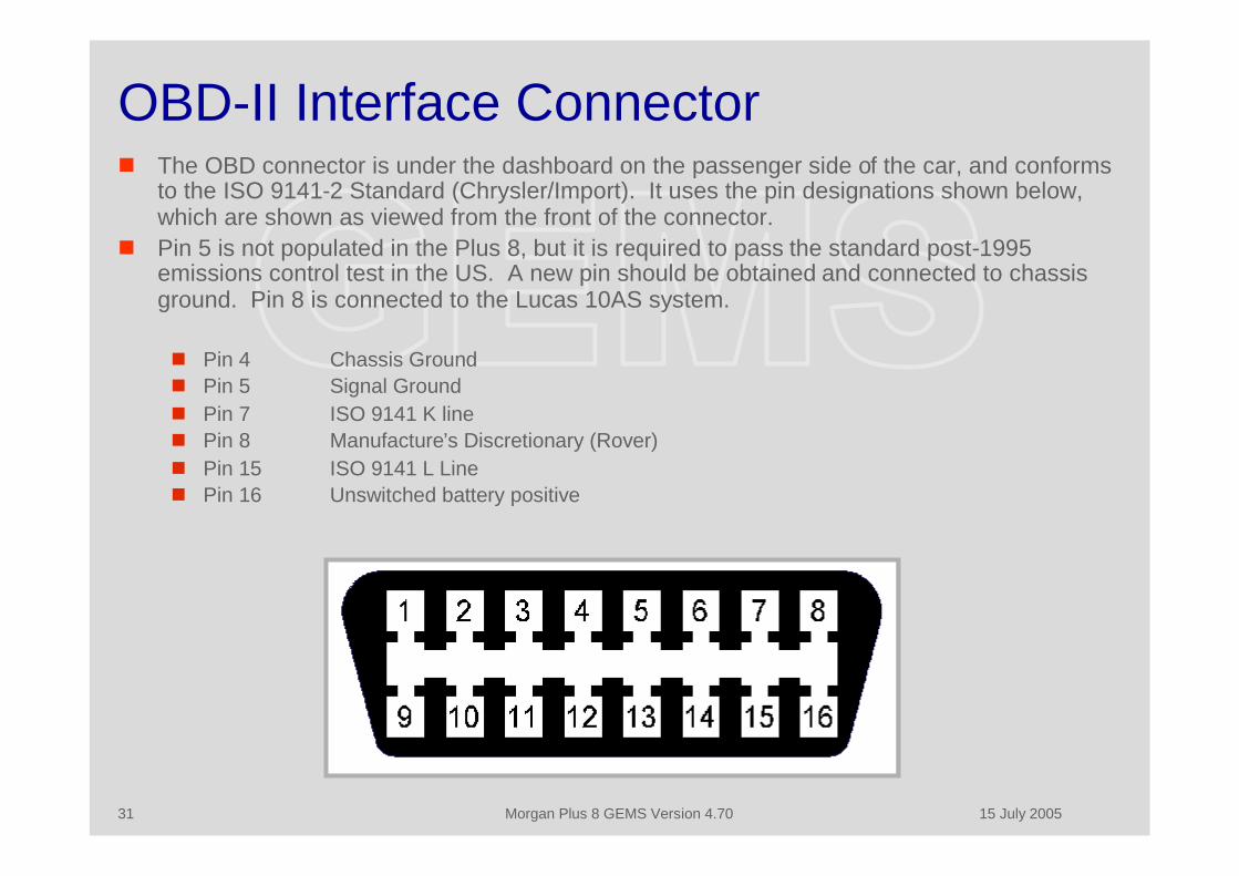
OBD-II Interface Connector The OBD connector is under the dashboard on the passenger side of the car, and conforms
to the ISO 9141-2 Standard (Chrysler/Import). It uses the pin designations shown below,which are shown as viewed from the front of the connector.
Pin 5 is not populated in the Plus 8, but it is required to pass the standard post-1995emissions control test in the US. A new pin should be obtained and connected to chassisground. Pin 8 is connected to the Lucas 10AS system.
Pin 4 Chassis Ground Pin 5 Signal Ground Pin 7 ISO 9141 K line Pin 8 Manufacture’s Discretionary (Rover) Pin 15 ISO 9141 L Line Pin 16 Unswitched battery positive
15 July 2005Morgan Plus 8 GEMS Version 4.7032
GEMS Data There are different categories of data available from GEMS that can be read
through the OBD interface, and there are also some data that can be sent toGEMS, including a reset to initialize the adaptive data, and commands to operatevarious control functions such as the fuel pump.
The data and resets available to both generic OBD and Rovacom diagnostic unitsare: Generic data which includes general operational parameters such as vehicle speed,
ignition advance, engine speed, oxygen sensor output, water temperature, etc. Trouble Codes (generic and enhanced)
The data available to only an OBD diagnostic unit is: The OBD monitors (OBDM) which monitor critical emission-specific subsystems and
parameters, and which must be set in order to pass the emissions inspection.
The data and resets available to only the Rovacom diagnostic units are: The GEMS specific data, such as adaptive settings, idle data and security settings All other system setup, reset, and command functions
15 July 2005Morgan Plus 8 GEMS Version 4.7033
Reading DTCs The OBD standard provides for a number of Diagnostic Trouble Codes (DTC) that are used
to identify failures in the operation of the ECM. The DTCs fall into two main categories –generic codes and manufacturer-enhanced codes. Generic OBD diagnostic computers willidentify both the numeric identifier and descriptive text string for the generic codes, but willusually only show the numeric identifier for the manufacturer-enhanced codes.
The Diagnostic Trouble Codes (DTCs) have a character followed by four digits: the firstcharacter in the DTCs refers to the major related system; P stands for Powertrain and is theonly one supported by GEMS.
The second character is a zero for a generic code or a “1” if it is a manufacturer enhancedcode (specific to the GEMS systems).
The third character in the code identifies the system where the fault occurred 1 and 2 are for fuel or air metering problems 3 is for ignition problems or engine misfire 4 is for auxiliary emission controls 5 relates to idle speed control problems 6 is for computer or output circuit faults 7 and 8 relate to transmission problems
A P0300 code (for instance) would indicate a random misfire. If the last digit is a numberother than zero, it corresponds to the cylinder number that is misfiring. A P0302 code, forexample, would indicate that cylinder number two is misfiring

15 July 2005Morgan Plus 8 GEMS Version 4.7034
OBD-II Data The following generic OBD data are available from the ECM through any OBD diagnostic
system
Calculated Engine Load Engine Coolant Temperature Engine Speed Fuel System Status Bank 1 Ignition Timing Advance Intake Air Temperature Long Term Fuel Trim Bank 1 Long Term Fuel Trim Bank 2 Mass Air Flow Rate O2 Sensor Bank 1 Sensor 1 O2 Sensor Bank 1 Sensor 2 O2 Sensor Bank 2 Sensor 1 O2 Sensor Bank 2 Sensor 2 Short Term Fuel Trim Bank 1 Short Term Fuel Trim Bank 2 Short Term Fuel Trim from O2 Sensor Bank 1 Sensor 1 Short Term Fuel Trim from O2 Sensor Bank 1 Sensor 2 Short Term Fuel Trim from O2 Sensor Bank 2 Sensor 1 Short Term Fuel Trim from O2 Sensor Bank 2 Sensor 2 Throttle Position Angle Vehicle Speed
15 July 2005Morgan Plus 8 GEMS Version 4.7035
OBD Monitors The OBD system uses a number of monitors (OBDM) to assure that the vehicle emissions
are within design limits. These monitors are actually computer flags that are set when theoutput from the monitor algorithm (each if which has a number of inputs) falls between twovalues.
There both continuous and non-continuous monitors – but in order to set them all the vehiclemust be driven through a complete drive cycle
The emissions tests (in the USA) for post ’95 vehicles do not use an exhaust analysis/rollingroad test but instead read the OBDM though the diagnostic interface. A maximum of oneOBDM can be in the “Incomplete” or “Fail” state if the vehicle is to pass..
The monitors used in the Plus 8 (with the MMC chips) are: Catalyst Monitor Status Comprehensive Component Monitoring Status Evaporative System Monitor Status Fuel System Monitor Status Misfire Monitor Status O2 Sensor Heater Monitor Status O2 Sensor Monitor Status OBD Requirements - CARB
15 July 2005Morgan Plus 8 GEMS Version 4.7036
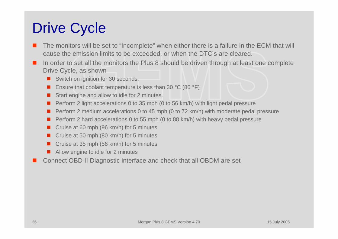
Drive Cycle The monitors will be set to “Incomplete” when either there is a failure in the ECM that will
cause the emission limits to be exceeded, or when the DTC’s are cleared. In order to set all the monitors the Plus 8 should be driven through at least one complete
Drive Cycle, as shown Switch on ignition for 30 seconds. Ensure that coolant temperature is less than 30 °C (86 °F) Start engine and allow to idle for 2 minutes. Perform 2 light accelerations 0 to 35 mph (0 to 56 km/h) with light pedal pressure Perform 2 medium accelerations 0 to 45 mph (0 to 72 km/h) with moderate pedal pressure Perform 2 hard accelerations 0 to 55 mph (0 to 88 km/h) with heavy pedal pressure Cruise at 60 mph (96 km/h) for 5 minutes Cruise at 50 mph (80 km/h) for 5 minutes Cruise at 35 mph (56 km/h) for 5 minutes Allow engine to idle for 2 minutes
Connect OBD-II Diagnostic interface and check that all OBDM are set

15 July 2005Morgan Plus 8 GEMS Version 4.7037
Engine Control Module
15 July 2005Morgan Plus 8 GEMS Version 4.7038
Engine Control Module The ECM is located in front of the bulkhead on the passenger side, under a
sloping stainless steel housing. The ECM can be removed by using the followingprocedure. It is not necessary to disconnect the battery before removing theECM. Cover the wing with a soft cloth to protect it in case the ECM is accidentally dropped. Lift the rubber flap and disconnect the three connectors. They have a retaining tab that
is released by pressing the plastic bar at the center of the connector – the two blackconnectors have this bar at the top and the red one has it at the bottom.
Wearing protective gloves, remove the four screws that retain the stainless steelhousing and remove it from the car. The housing has extremely sharp edges and it isvery easy to cut yourself on it.
With the housing the on the workbench remove the two screws retaining the ECM andslide it out.
Installation is the reverse of the above procedure.
15 July 2005Morgan Plus 8 GEMS Version 4.7039
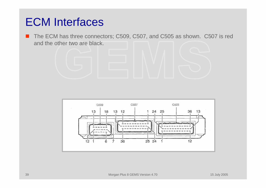
ECM Interfaces The ECM has three connectors; C509, C507, and C505 as shown. C507 is red
and the other two are black.

15 July 2005Morgan Plus 8 GEMS Version 4.7040
C509 Pin DesignationsPin No. Description Input/Output Voltage
1 Coil driver - Cylinders 5 & 8 Output 0 - 1 2V2 Not used3 Not used4 Throttle Position Sensor Output 5V supply5 ECM to chassis ground Ground 0V6 Not used7 Main relay supply Input 0 - 12V8 Ignition sense Input 0 - 12V9 ECM to chassis ground Ground 0V
10 ECM to chassis ground Ground 0V11 Crankshaft(CKP)sensor-ve Ground 0V12 Crankshaft (CKP) sensor +ve Analogue input 18V (average) at 480Hz13 Coil driver - Cylinders 2 & 3 Output 0 - 12V14 Coil driver - Cylinders 1 & 6 Output 0 - 12V15 Coil driver - Cylinders 4 & 7 Output 0 - 12V16 ECM to chassis ground Ground 0V17 Main relay control Output Switched to ground18 Not used
15 July 2005Morgan Plus 8 GEMS Version 4.7041
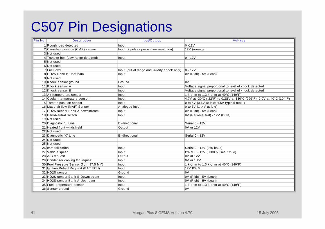
C507 Pin DesignationsPin No. Description Input/Output Voltage
1 Rough road detected Input 0 -12V2 Camshaft position (CMP) sensor Input (2 pulses per engine revolution) 12V (average)3 Not used4 Transfer box (Low range detected) Input 0 - 12V5 Not used6 Not used7 Fuel level Input (out of range and validity check only) 0 - 12V8 HO2S Bank B Upstream Input 0V (Rich) - 5V (Lean)9 Not used
10 Knock sensor ground Ground 0V11 Knock sensor A Input Voltage signal proportional to level of knock detected12 Knock sensor B Input Voltage signal proportional to level of knock detected13 Air temperature sensor Input 1 k-ohm to 1.3 k-ohm at 40°C (140°F)14 Coolant temperature sensor Input 4.7V at -30°C (-22°F) to 0.2SV at 130°C (266°F); 2.0V at 40°C (104°F)15 Throttle position sensor Input 0 to 5V (0.6V at idle; 4.5V typical max.)16 Mass air flow (MAF) Sensor Analogue input 0 to 5V (1 .4V at idle)17 HO2S sensor Bank A downstream Input 0V (Rich) - 5V (Lean)18 Park/Neutral Switch Input 0V (Park/Neutral) - 12V (Drive)19 Not used20 Diagnostic ‘L’ Line Bi-directional Serial 0 - 12V21 Heated front windshield Output 0V or 12V22 Not used23 Diagnostic ‘K’ Line Bi-directional Serial 0 - 12V24 Not used25 Not used26 Immobilization Input Serial 0 - 12V (366 baud)27 Vehicle speed Input PWM 0 - 12V (8000 pulses / mile)28 A/C request Output 0V or 12V29 Condenser cooling fan request Input 0V or 1 2V30 Fuel Pressure Sensor (from 97.5 MY) Input 1 k-ohm to 1.3 k-ohm at 40°C (140°F)31 Ignition Retard Request (EAT ECU) Input 12V PWM32 HO2S sensor Ground 0V33 HO2S sensor Bank B Downstream Input 0V (Rich) - 5V (Lean)34 HO2S sensor Bank A Upstream Input 0V (Rich) - 5V (Lean)35 Fuel temperature sensor Input 1 k-ohm to 1.3 k-ohm at 40°C (140°F)36 Sensor ground Ground 0V
15 July 2005Morgan Plus 8 GEMS Version 4.7042
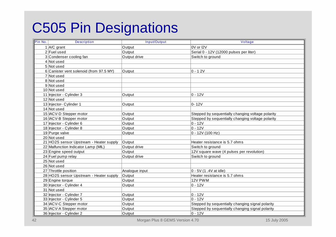
C505 Pin DesignationsPin No. Description Input/Output Voltage
1 A/C grant Output 0V or l2V2 Fuel used Output Serial 0 - 12V (12000 pulses per liter)3 Condenser cooling fan Output drive Switch to ground4 Not used5 Not used6 Canister vent solenoid (from 97.5 MY) Output 0 - 1 2V7 Not used8 Not used9 Not used
10 Not used11 Injector - Cylinder 3 Output 0 - 12V12 Not used13 Injector- Cylinder 1 Output 0- 12V14 Not used15 IACV-D Stepper motor Output Stepped by sequentially changing voltage polarity16 lACV-B Stepper motor Output Stepped by sequentially changing voltage polarity17 Injector - Cylinder 6 Output 0 - 12V18 Injector - Cylinder 8 Output 0 - 12V19 Purge valve Output 0 - 12V (100 Hz)20 Not used21 HO2S sensor Upstream - Heater supply Output Heater resistance is 5.7 ohms22 Malfunction Indicator Lamp (MIL) Output drive Switch to ground23 Engine speed output Output 12V square wave (4 pulses per revolution)24 Fuel pump relay Output drive Switch to ground25 Not used26 Not used27 Throttle position Analogue input 0 - 5V (1 .4V at idle)28 HO2S sensor Upstream - Heater supply Output Heater resistance is 5.7 ohms29 Engine torque Output 12V PWM30 Injector - Cylinder 4 Output 0 - 12V31 Not used32 Injector - Cylinder 7 Output 0 - 12V33 Injector - Cylinder 5 Output 0 - 12V34 IACV-C Stepper motor Output Stepped by sequentially changing signal polarity35 IACV-A Stepper motor Output Stepped by sequentially changing signal polarity36 Injector - Cylinder 2 Output 0 - 12V
15 July 2005Morgan Plus 8 GEMS Version 4.7043
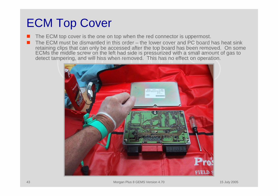
ECM Top Cover The ECM top cover is the one on top when the red connector is uppermost. The ECM must be dismantled in this order – the lower cover and PC board has heat sink
retaining clips that can only be accessed after the top board has been removed. On someECMs the middle screw on the left had side is pressurized with a small amount of gas todetect tampering, and will hiss when removed. This has no effect on operation.
15 July 2005Morgan Plus 8 GEMS Version 4.7044
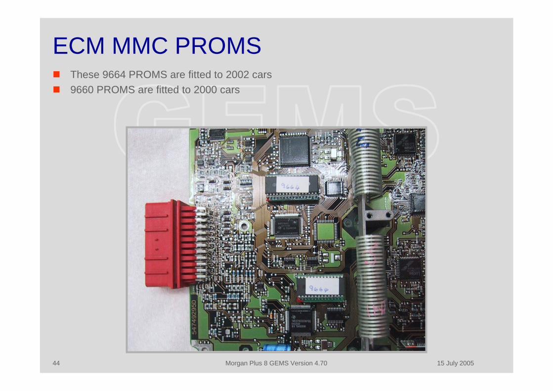
ECM MMC PROMS These 9664 PROMS are fitted to 2002 cars 9660 PROMS are fitted to 2000 cars

15 July 2005Morgan Plus 8 GEMS Version 4.7045
ECM T9619 PROMS The main aftermarket PROM supplier is RPi, who supply Tornado chips The smaller PROM is the DSP and is not changed as the version changes The larger PROM is an experimental version for US certification

15 July 2005Morgan Plus 8 GEMS Version 4.7046
EMS Components
15 July 2005Morgan Plus 8 GEMS Version 4.7047
There are a number of sensors, actuators, relays, injectors, ignition componentsand relays associated with the GEMS systems. These, together with the ECMform the Engine Management System.
Most components can be obtained from LR dealers, or British Atlantic in the USAand specialist LR suppliers in UK and Europe.
The system appears to be derived from the NAS specification 1998 Defender, butwith a manual transmission fitted. The 1998 Discovery I is also very similar.
EMS Components
15 July 2005Morgan Plus 8 GEMS Version 4.7048
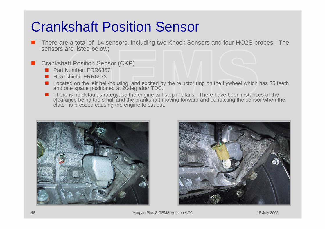
Crankshaft Position Sensor There are a total of 14 sensors, including two Knock Sensors and four HO2S probes. The
sensors are listed below;
Crankshaft Position Sensor (CKP) Part Number: ERR6357 Heat shield: ERR6573 Located on the left bell-housing, and excited by the reluctor ring on the flywheel which has 35 teeth
and one space positioned at 20deg after TDC. There is no default strategy, so the engine will stop if it fails. There have been instances of the
clearance being too small and the crankshaft moving forward and contacting the sensor when theclutch is pressed causing the engine to cut out.

15 July 2005Morgan Plus 8 GEMS Version 4.7049
Camshaft Position Sensor Camshaft Position Sensor (CMP)
Part Number: ERR6169 Bracket: ERR7170 O-Ring: ERR4815 This sensor is located on the engine front cover. It produces four pulses (three long
and one short) every revolution of the cam, or every two revolutions of the engine (toidentify the firing stroke). If you change the cam you have to make sure that you use aGEMS gear and not one from an earlier or later engine. It is also the reason that youcannot change to a two-row timing chain on this engine.
In the event of failure the defaultstrategy is to continue normaloperation, but the injection may beone revolution out ofsynchronization. This is “not easilydetected by the driver” to quoteone source. The ignition willoperate as normal since GEMSproduces a spark on both exhaustand compression strokes.
15 July 2005Morgan Plus 8 GEMS Version 4.7050
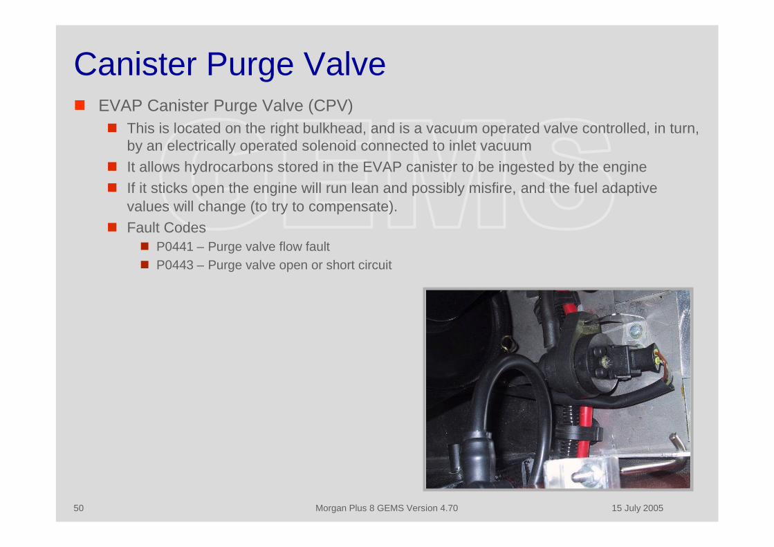
Canister Purge Valve EVAP Canister Purge Valve (CPV)
This is located on the right bulkhead, and is a vacuum operated valve controlled, in turn,by an electrically operated solenoid connected to inlet vacuum
It allows hydrocarbons stored in the EVAP canister to be ingested by the engine If it sticks open the engine will run lean and possibly misfire, and the fuel adaptive
values will change (to try to compensate). Fault Codes
P0441 – Purge valve flow fault P0443 – Purge valve open or short circuit
15 July 2005Morgan Plus 8 GEMS Version 4.7051
Canister Vent Solenoid EVAP Canister Vent Solenoid (CVS)
This is located on the EVAP canister, which is on the right side of the fuel tank, andaccounts for the missing 3 gallons in the “advanced evaps” cars which have a 12 Gallon(US) tank instead of the 15 gallon tank formerly fitted
It is used during the fuel system pressure test carried out automatically by the ECM aspart of the tank leak check.
15 July 2005Morgan Plus 8 GEMS Version 4.7052
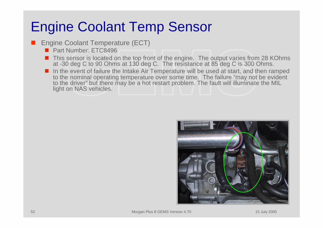
Engine Coolant Temp Sensor Engine Coolant Temperature (ECT)
Part Number: ETC8496 This sensor is located on the top front of the engine. The output varies from 28 KOhms
at -30 deg C to 90 Ohms at 130 deg C. The resistance at 85 deg C is 300 Ohms. In the event of failure the Intake Air Temperature will be used at start, and then ramped
to the nominal operating temperature over some time. The failure “may not be evidentto the driver” but there may be a hot restart problem. The fault will illuminate the MILlight on NAS vehicles.

15 July 2005Morgan Plus 8 GEMS Version 4.7053
Engine Fuel Temp Sensor Engine Fuel Temperature (EFT)
Part Number: ETC8496 This sensor is located on the fuel rail on the left front of the engine, and is used to
modify injector pulse width during hot restarts. A nominal value is used in the event of a failure, which may cause a hot restart
problem. The fault will illuminate the MIL light on NAS vehicles.
15 July 2005Morgan Plus 8 GEMS Version 4.7054
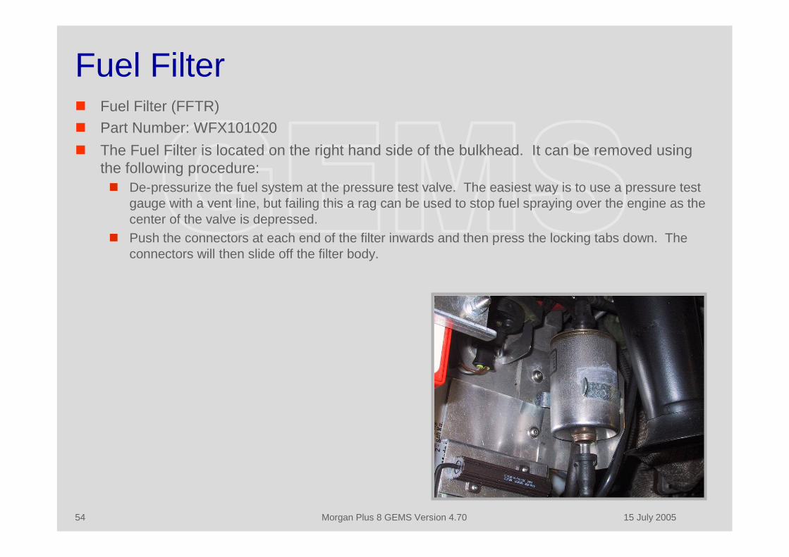
Fuel Filter Fuel Filter (FFTR) Part Number: WFX101020 The Fuel Filter is located on the right hand side of the bulkhead. It can be removed using
the following procedure: De-pressurize the fuel system at the pressure test valve. The easiest way is to use a pressure test
gauge with a vent line, but failing this a rag can be used to stop fuel spraying over the engine as thecenter of the valve is depressed.
Push the connectors at each end of the filter inwards and then press the locking tabs down. Theconnectors will then slide off the filter body.
15 July 2005Morgan Plus 8 GEMS Version 4.7055
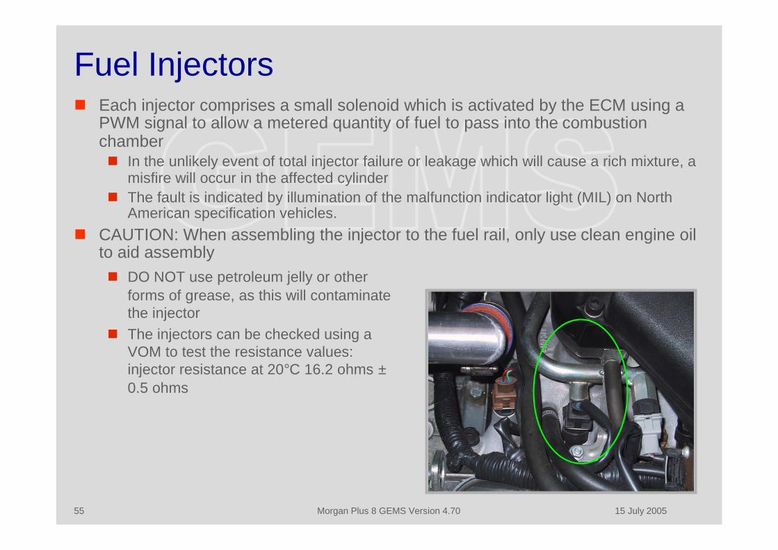
Fuel Injectors Each injector comprises a small solenoid which is activated by the ECM using a
PWM signal to allow a metered quantity of fuel to pass into the combustionchamber In the unlikely event of total injector failure or leakage which will cause a rich mixture, a
misfire will occur in the affected cylinder The fault is indicated by illumination of the malfunction indicator light (MIL) on North
American specification vehicles. CAUTION: When assembling the injector to the fuel rail, only use clean engine oil
to aid assembly DO NOT use petroleum jelly or other
forms of grease, as this will contaminatethe injector
The injectors can be checked using aVOM to test the resistance values:injector resistance at 20°C 16.2 ohms ±0.5 ohms
15 July 2005Morgan Plus 8 GEMS Version 4.7056
Fuel Injector Fault Codes P0201 - Injector circuit fault, cylinder I P0202 - Injector circuit fault, cylinder 2 P0203 - Injector circuit fault, cylinder 3 P0204 - Injector circuit fault, cylinder 4 P0205 - Injector circuit fault, cylinder 5 P0206 - Injector circuit fault, cylinder 6 P0207 - Injector circuit fault, cylinder 7 P0208 - Injector circuit fault, cylinder 8 P1201 - Injector circuit open or ground short, cylinder 1 P1202 - Injector circuit open or ground short, cylinder 2 P1203 - Injector circuit open or ground short, cylinder 3 P1204 - Injector circuit open or ground short, cylinder 4 P1205 - Injector circuit open or ground short, cylinder 5 P1206 - Injector circuit open or ground short, cylinder 6 P1207 - Injector circuit open or ground short, cylinder 7 P1208 - Injector circuit open or ground short, cylinder 8
15 July 2005Morgan Plus 8 GEMS Version 4.7057
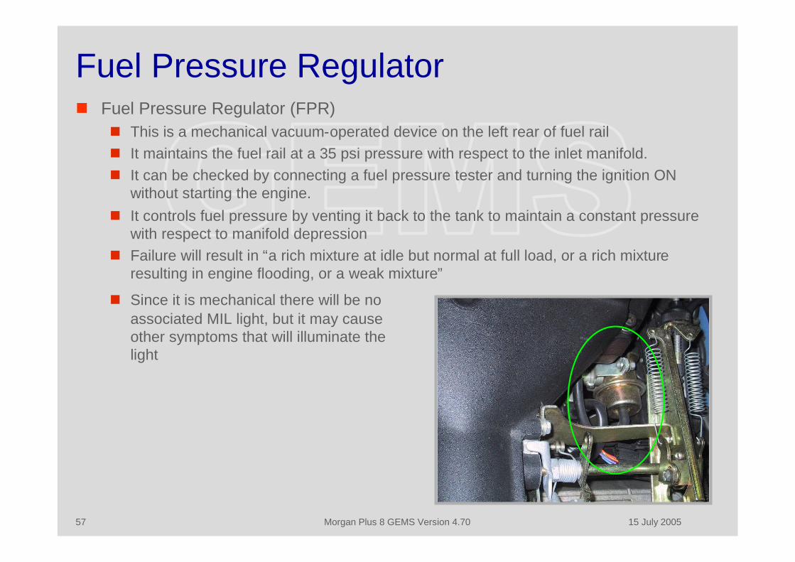
Fuel Pressure Regulator Fuel Pressure Regulator (FPR)
This is a mechanical vacuum-operated device on the left rear of fuel rail It maintains the fuel rail at a 35 psi pressure with respect to the inlet manifold. It can be checked by connecting a fuel pressure tester and turning the ignition ON
without starting the engine. It controls fuel pressure by venting it back to the tank to maintain a constant pressure
with respect to manifold depression Failure will result in “a rich mixture at idle but normal at full load, or a rich mixture
resulting in engine flooding, or a weak mixture”
Since it is mechanical there will be noassociated MIL light, but it may causeother symptoms that will illuminate thelight
15 July 2005Morgan Plus 8 GEMS Version 4.7058
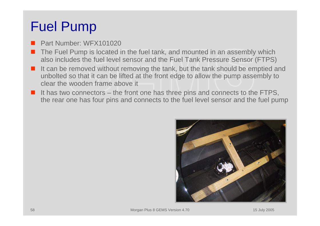
Fuel Pump Part Number: WFX101020 The Fuel Pump is located in the fuel tank, and mounted in an assembly which
also includes the fuel level sensor and the Fuel Tank Pressure Sensor (FTPS) It can be removed without removing the tank, but the tank should be emptied and
unbolted so that it can be lifted at the front edge to allow the pump assembly toclear the wooden frame above it
It has two connectors – the front one has three pins and connects to the FTPS,the rear one has four pins and connects to the fuel level sensor and the fuel pump
15 July 2005Morgan Plus 8 GEMS Version 4.7059
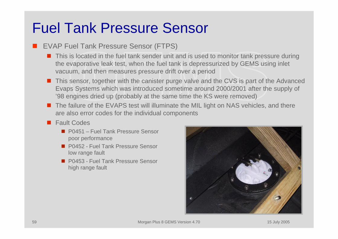
Fuel Tank Pressure Sensor EVAP Fuel Tank Pressure Sensor (FTPS)
This is located in the fuel tank sender unit and is used to monitor tank pressure duringthe evaporative leak test, when the fuel tank is depressurized by GEMS using inletvacuum, and then measures pressure drift over a period
This sensor, together with the canister purge valve and the CVS is part of the AdvancedEvaps Systems which was introduced sometime around 2000/2001 after the supply of’98 engines dried up (probably at the same time the KS were removed)
The failure of the EVAPS test will illuminate the MIL light on NAS vehicles, and thereare also error codes for the individual components
Fault Codes P0451 – Fuel Tank Pressure Sensor
poor performance P0452 - Fuel Tank Pressure Sensor
low range fault P0453 - Fuel Tank Pressure Sensor
high range fault
15 July 2005Morgan Plus 8 GEMS Version 4.7060
IACV Actuator - 1 Idle Air Control Valve (IACV)
Part Number: ERR4352Gasket: ERR3359 Bleed air bypass blanking plug: ETC 6874 The idle speed control stepper motor is located on the side of the inlet
manifold. Idle speed is controlled by the stepper motor, which comprises twocoils, mounted to the throttle housing
When energized in the correct sequence the coils move a plunger whichopens or closes the throttle bypass valve controlling the quantity of idle air
The stepper motor controls idle speed by moving the plunger a set distancecalled a step
Fully open is 200 steps (180 steps for pre-advanced evaps vehicles) and fullyclosed 0 steps
It must be set to between 15 and 30 steps at hot idle by the adjustment of thebleed air bypass, located under a blanking lug on top of the throttle body, toensure stable idle operation
Failure of the stepper motor will result in low or high idle speed, poor idle,engine stall or non start

15 July 2005Morgan Plus 8 GEMS Version 4.7061
IACV Actuator - 2 If the number of recorded steps changes beyond a set threshold (opening or
closing) without a corresponding change in airflow, then a fault code will bestored
The GEMS diagnostics also check for short circuit conditions during normalstepper operation and open circuit during power down. Detected faults areindicated by illumination of the malfunction indicator light (MIL) on NorthAmerican specification vehicles
The IACV may become contaminated or oxidized in vehicles that are notdriven often, and this may result in an unreliable idle. If this occurs the IACVshould be removed and the pintle valve and housing cleaned with carburetorcleaner.
CAUTION: The pintle must not bemoved by force
The stepper motor coil resistance is53 ohms ± 2 ohmsFault codes:
P0506 - Low idle speed P0507 - High idle speed P1508 - IACV stepper motor open
circuit P1509 - IACV stepper motor short
circuitThere is no default strategy, and the
fault will illuminate the MIL light onNAS vehicles
15 July 2005Morgan Plus 8 GEMS Version 4.7062
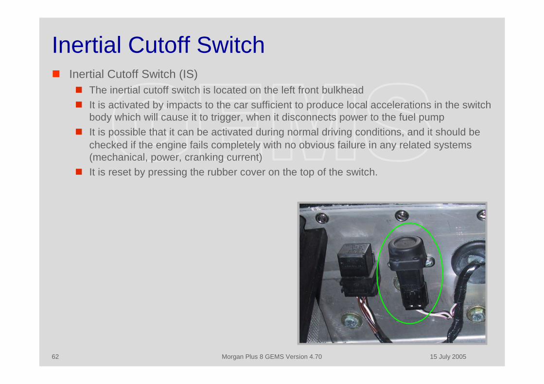
Inertial Cutoff Switch Inertial Cutoff Switch (IS)
The inertial cutoff switch is located on the left front bulkhead It is activated by impacts to the car sufficient to produce local accelerations in the switch
body which will cause it to trigger, when it disconnects power to the fuel pump It is possible that it can be activated during normal driving conditions, and it should be
checked if the engine fails completely with no obvious failure in any related systems(mechanical, power, cranking current)
It is reset by pressing the rubber cover on the top of the switch.
15 July 2005Morgan Plus 8 GEMS Version 4.7063
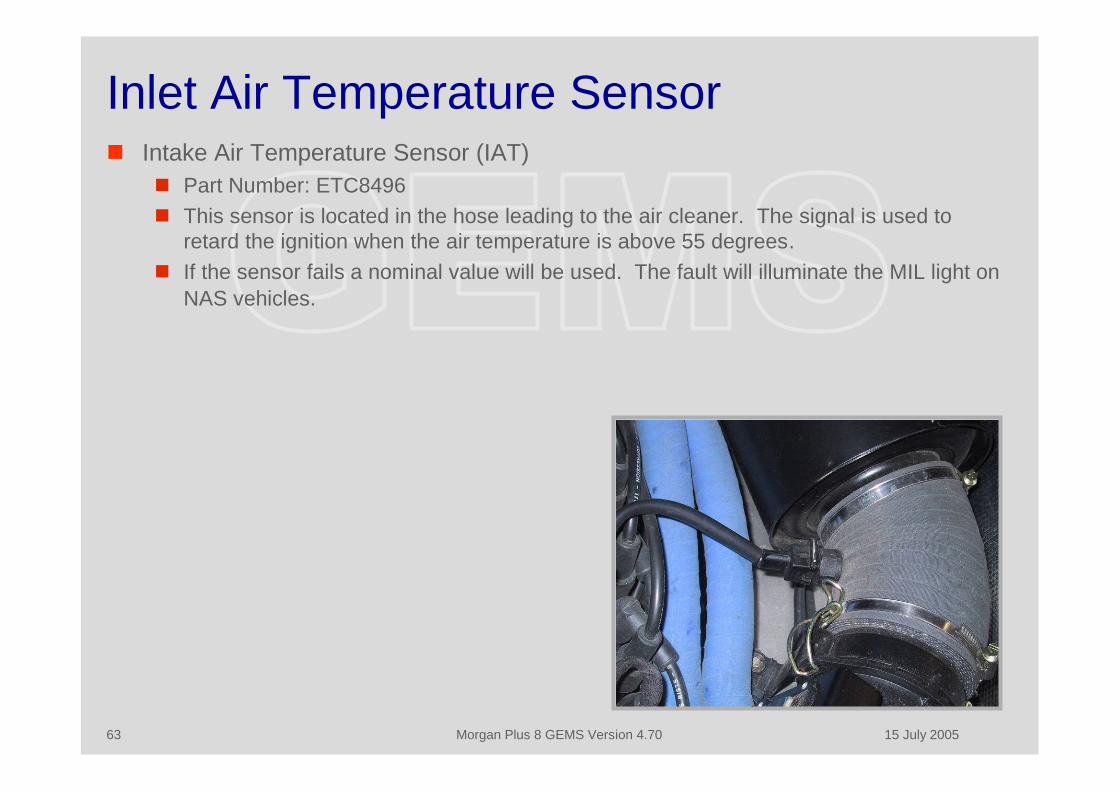
Inlet Air Temperature Sensor Intake Air Temperature Sensor (IAT)
Part Number: ETC8496 This sensor is located in the hose leading to the air cleaner. The signal is used to
retard the ignition when the air temperature is above 55 degrees. If the sensor fails a nominal value will be used. The fault will illuminate the MIL light on
NAS vehicles.

15 July 2005Morgan Plus 8 GEMS Version 4.7064
Knock Sensors - 1 Knock Sensors (KS)
Part Number: ERR5594 These sensors are located on either side of the engine on the crankcase below the
exhaust manifolds. They have not been fitted by Morgan (well, to be fair, I think thatthey are in the hands of their engine suppliers) since around 2000/2001, and I presumethat the GEMS ignition map was changed at the same time. The ECM calculates knockon a per-cylinder basis, and then progressively retards the ignition (up to 4 degrees Ibelieve) until the knock stops, when it progressively advances it, etc, and then storesthe value. In the event of knock occurring each cylinder can (will) have a differentignition timing.
Sensor failure is detected throughbackground noise being low or high,although this is disabled in the standardMorgan PROMs. The KS are alsodisabled if the CMP fails since GEMScannot detect the cylinder that isknocking.
There are 6 fault codes: P0326 – Continuous knock on Bank A P0327 – Knock background low, Bank A P0328 – Knock background high, Bank A P0331 – Continuous knock on Bank B P0332 – Knock background low, Bank B P0333 – Knock background high, Bank B
Knock sensor failure will illuminate theMIL light.
15 July 2005Morgan Plus 8 GEMS Version 4.7065
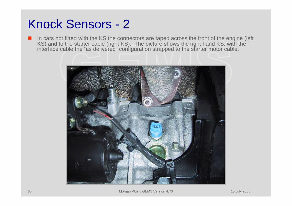
Knock Sensors - 2 In cars not fitted with the KS the connectors are taped across the front of the engine (left
KS) and to the starter cable (right KS). The picture shows the right hand KS, with theinterface cable the “as delivered” configuration strapped to the starter motor cable.
15 July 2005Morgan Plus 8 GEMS Version 4.7066
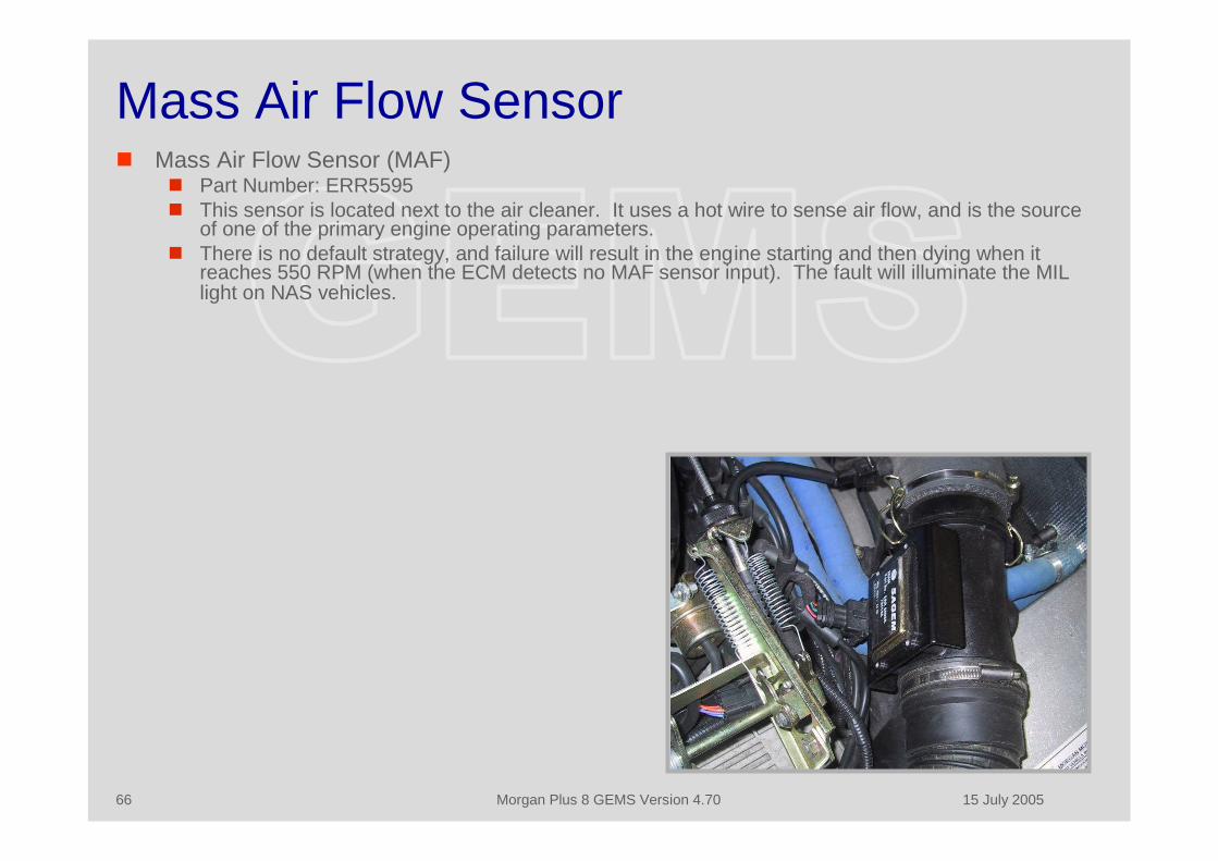
Mass Air Flow Sensor Mass Air Flow Sensor (MAF)
Part Number: ERR5595 This sensor is located next to the air cleaner. It uses a hot wire to sense air flow, and is the source
of one of the primary engine operating parameters. There is no default strategy, and failure will result in the engine starting and then dying when it
reaches 550 RPM (when the ECM detects no MAF sensor input). The fault will illuminate the MILlight on NAS vehicles.
15 July 2005Morgan Plus 8 GEMS Version 4.7067
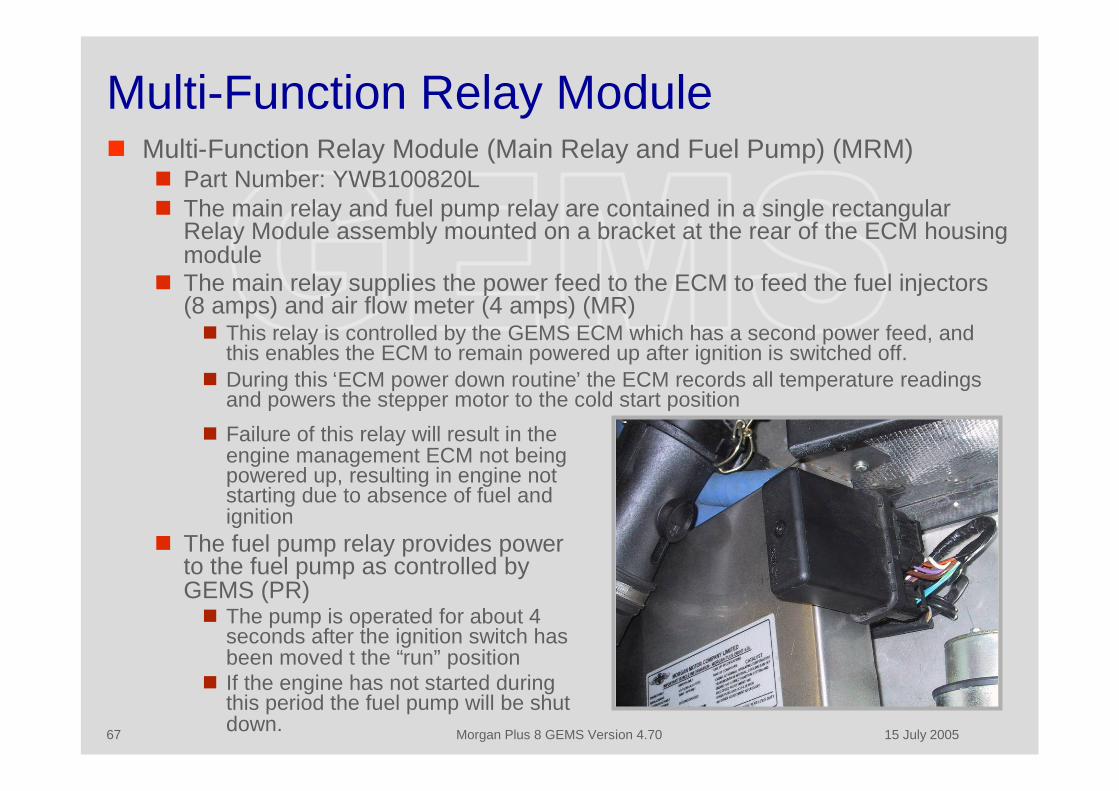
Multi-Function Relay Module Multi-Function Relay Module (Main Relay and Fuel Pump) (MRM)
Part Number: YWB100820L The main relay and fuel pump relay are contained in a single rectangular
Relay Module assembly mounted on a bracket at the rear of the ECM housingmodule
The main relay supplies the power feed to the ECM to feed the fuel injectors(8 amps) and air flow meter (4 amps) (MR)This relay is controlled by the GEMS ECM which has a second power feed, and
this enables the ECM to remain powered up after ignition is switched off.During this ‘ECM power down routine’ the ECM records all temperature readings
and powers the stepper motor to the cold start position
Failure of this relay will result in theengine management ECM not beingpowered up, resulting in engine notstarting due to absence of fuel andignition
The fuel pump relay provides powerto the fuel pump as controlled byGEMS (PR)The pump is operated for about 4
seconds after the ignition switch hasbeen moved t the “run” position
If the engine has not started duringthis period the fuel pump will be shutdown.

15 July 2005Morgan Plus 8 GEMS Version 4.7068
Oxygen Sensors Heated Oxygen Sensor (HO2S) (Lambda Probe)
Part Number: ERR1834/AMR6244 The oxygen sensors are located in the sections of exhaust pipe in front and behind the
catalytic converters, and form part of the closed loop operation of the engine The fuel injection pulse width is modulated by the feedback from front sensors to achieve
correct oxygen levels in the exhaust; the rear sensors are used to check correct catalyticconverter operation
If the connections to the sensors are crossed, one bank will go very rich and the other very leanwith black smoke and misfires
The heaters are controlled by a pulse width modulated signal, so that the temperaturecan be controlled during start The oxygen sensors are heated to ensure rapid warm up and continued operation when the
exhaust temperature may be below the working temperature of the sensor - both the upstreamsensor heaters and the downstream sensor heaters are connected in parallel
In the event of an O2 sensor failure, the system will default to ‘open loop’ operation Fuelling will be calculated using signals from the remaining ECM inputs A fault with any of the HO2S sensors is indicated by illumination of the malfunction indicator
light (MIL) ECM diagnostics also use the Heated Oxygen Sensors to detect catalyst damage, misfire and
fuel system faults CAUTION: Tighten the sensor to 15lbs/ft when fitting CAUTION: Although robust within the vehicle environment, Heated Oxygen Sensors are
easily damaged by dropping, excessive heat and contamination. Care must beexercised when working on the exhaust system not to damage the sensor housing or tip

15 July 2005Morgan Plus 8 GEMS Version 4.7069
Oxygen Sensor Fault Codes - 1 P0130 - Oxygen sensor circuit slow response, upstream sensor bank A P0136 - Oxygen sensor circuit slow response, upstream sensor bank A P0150 - Oxygen sensor circuit slow response, upstream sensor bank B P0156 - Oxygen sensor circuit slow response, upstream sensor bank B P0131 - Oxygen sensor circuit low voltage, upstream sensor bank A P0151 - Oxygen sensor circuit low voltage, upstream sensor bank B P0137 - Oxygen sensor circuit low voltage, downstream sensor bank A P0157 - Oxygen sensor circuit low voltage, downstream sensor bank B P0132 - Oxygen sensor circuit high voltage, upstream sensor bank A P0152 - Oxygen sensor circuit high voltage, upstream sensor bank B P0138 - Oxygen sensor circuit high voltage, downstream sensor bank A P0158 - Oxygen sensor circuit high voltage, downstream sensor bank B P0133 - Oxygen sensor circuit slow response, upstream sensor bank A P0153 - Oxygen sensor circuit slow response, upstream sensor bank B P0139 - Oxygen sensor circuit slow response, downstream sensor bank A P0159 - Oxygen sensor circuit slow response, downstream sensor bank B P1138 - Oxygen sensor problem with switching lean, sensor(s) for bank A P1158 - Oxygen sensor problem with switching lean, sensor(s) for bank B P1137 - Oxygen sensor problem with switching rich, sensor(s) for bank A P1157 - Oxygen sensor problem with switching rich, sensor(s) for bank B P1139 - Oxygen sensor circuit switching period too long bank A P1159 - Oxygen sensor circuit switching period too long bank B P1171 - System too lean bank A and bank B P1172 - System too rich bank A and bank B
15 July 2005Morgan Plus 8 GEMS Version 4.7070
Oxygen Sensor Fault Codes - 2 P0171 - System too lean bank A P0174 - System too lean bank B P0172 - System too rich bank A P0175 - System too rich bank B P1185 - Oxygen sensor heater circuit open circuit, upstream sensors P1186 - Oxygen sensor heater circuit short circuit, upstream sensors P1187 - Oxygen sensor heater circuit inferred open circuit, upstream sensors P1188 - Oxygen sensor heater circuit high resistance, upstream sensors P1189 - Oxygen sensor heater circuit inferred low resistance, upstream sensors P1190 - Oxygen sensor heater circuit low resistance, upstream sensors P1191 - Oxygen sensor heater circuit open circuit, downstream sensors P1192 - Oxygen sensor heater circuit short circuit, downstream sensors P1193 - Oxygen sensor heater circuit inferred open circuit, downstream sensors
P1194 - Oxygen sensor heater circuit high resistance, downstream sensors P1195 - Oxygen sensor heater circuit inferred low resistance, downstream sensors P1196 - Oxygen sensor heater circuit low resistance, downstream sensors P0420 - Catalyst efficiency is low, bank A P0430 - Catalyst efficiency is low, bank B
15 July 2005Morgan Plus 8 GEMS Version 4.7071
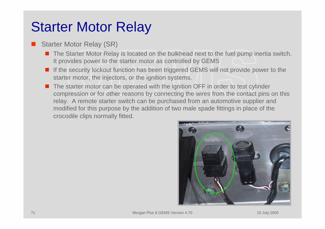
Starter Motor Relay Starter Motor Relay (SR)
The Starter Motor Relay is located on the bulkhead next to the fuel pump inertia switch.It provides power to the starter motor as controlled by GEMS
If the security lockout function has been triggered GEMS will not provide power to thestarter motor, the injectors, or the ignition systems.
The starter motor can be operated with the ignition OFF in order to test cylindercompression or for other reasons by connecting the wires from the contact pins on thisrelay. A remote starter switch can be purchased from an automotive supplier andmodified for this purpose by the addition of two male spade fittings in place of thecrocodile clips normally fitted.

15 July 2005Morgan Plus 8 GEMS Version 4.7072
Throttle Position Sensor Throttle Position Sensor (TP)
Part Number: ERR4278 Mounting Plate: ERR5023 This sensor is mounted on the throttle body in line with the throttle shaft. The signal
varies from 0 to 5 volts, and is used (mainly) for acceleration and idle purposes. If it ischanged the GEMS closed throttle voltage must be reset..
There is a default strategy. GEMScorrelates throttle position with thecorrected MAF, which in turn iscorrelated against the fuel data (injectorpulse width, RPM, lambda probedata). If the TP data does not correlatecorrectly the TP is assumed to havefailed and GEMS calculates default datafrom corrected MAF, which may“adversely affect accelerationperformance”. The fault will illuminatethe MIL light on NAS vehicles.
15 July 2005Morgan Plus 8 GEMS Version 4.7073
Other Interfaces Vehicle Speed
The vehicle speed sensor is located on the lower left hand side of the gearbox It provides a square wave input to GEMS proportional to road speed (8000 pulses/mile),
and is also used by the speedometer Transmission
There is provision for three inputs and outputs to the transmission; the inputs arePark/Neutral selector input, Ignition retard request and Low Gear Transfer rangeselected
The outputs are the Engine Torque, Engine Speed and Throttle Angle None of these interfaces are used in the Plus 8 or vehicles fitted manual transmission.
Fuel Level and Fuel Totalizer There is an input for fuel level, to prevent the GEMS from adapting to changes in engine
operating conditions caused by low fuel levels, and there is also a fuel totalizer output. Neither is used in the Plus 8.
Security System The Plus 8 is fitted with the Lucas 10AS secure immobilization system This is a complex system that uses a rolling code match between the 10AS and GEMS
to enable normal operations It is housed in a grey metal box attached at the center of the frame behind the
dashboard, and is capable of number of other functions including welcome and interiorlight activation, alarm sound and lights flash options, catalyst overheat monitoring, andanother 20 or so additional parameters
It is programmed through the OBD interface using a specialist module, which can beadded to the RovacomLite system.

15 July 2005Morgan Plus 8 GEMS Version 4.7074
Diagnostics

15 July 2005Morgan Plus 8 GEMS Version 4.7075
Diagnostics The GEMS system is very robust and the connectors and components are of high
quality. Most failures will result in a “Check Engine” light, and the engine willcontinue to operate more-or-less normally. There are only two sensors the failureof which will cause the engine to stop – these are the CKP and the MAF. The fuelpump is also (obviously) a critical component.
The “Check Engine” light can be reset and the associated DTC can be read withany ODB-II diagnostic tool for the Chrysler/Import (ISO-9141) standard. MostDTCs will point to an obvious problem, and the generic OBD data will help findany component that has failed, such as temperature sensors. The only functionsthat require a GEMS-specific diagnostic system are the manual/automatic andcapacity settings, adaptive parameter reset, idle setup and security settings.
Most failures seems to be associated with the idle performance and the Lucas10AS security system. Poor idle performance is generally due lack ofmaintenance which will result in a misadjusted or dirty IACV. The Lucas 10ASsystem is complex and easy to mis-configure, which will result in odd operationalcharacteristics.
15 July 2005Morgan Plus 8 GEMS Version 4.7076
Diagnostics – Failure to Start These procedures assume that the battery is charged and is capable of turning
the engine over, and that no DTCs have been set.
Fuel pump operates, and engine turns over but does not start. No “check engine”light with the ignition on. This usually indicates that the security is armed. Attempt to disarm it by cycling the
PLIP several times. If this fails a Rovacom will have to be used to perform a SecurityLearn procedure.
”Check engine” light on with the ignition, engine turns over and attempts to startbut then stops. Check that the fuel pump runs briefly when the ignition is turned on. If you do not hear
the fuel pump check the fuses. If the fuse is normal the fuel pump has failed and mustbe replaced.
If you do hear the fuel pump it is probable that the MAF sensor has failed and must bereplaced.

15 July 2005Morgan Plus 8 GEMS Version 4.7077
Diagnostics – Poor Idle If no sensors have failed a poor or unreliable idle is usually caused by either a
dirty IACV or by the bleed air bypass setting being incorrect. The IACV setting should be checked using Rovacom. It should be between 15-30
steps with the engine fully warmed and at idle. If it is not in this range the bleedair bypass should be adjusted. If it is in this range the IACV should be removedand cleaned.
The Stored Throttle Value should be checked using Rovacom – it should be thesame as the Current Throttle Position value. If the two values are different an“Adaptive Reset” should be performed and the values checked after performing aDrive Cycle. If the two values are again mismatched the TPS is faulty and shouldbe replaced.
If neither of the above correct the problem the IACV should be removed and theIACV and housing cleaned with carburetor cleaner or similar. Take care not tomove the pintle valve while you are cleaning it.
15 July 2005Morgan Plus 8 GEMS Version 4.7078
Diagnostics - Misfire A misfire can be caused by a number of things, including mechanical and
electrical items not monitored by GEMS. However, there have been reportedinstances of the Crankshaft Position Sensor hitting the flywheel reluctor ring andcausing an intermittent misfire.
This condition usually occurs when the clutch is pressed, which causes thecrankshaft to move to the fully forward position within the normal clearance in thebearings. Evidence of contact can clearly be seen if the CKP is removed, when awitness mark on the tip of the sensor from contact with the reluctor ring will beseen.
The CKP sensor is mounted in a sleeve which is bonded to the crankcase. Thefault is usually caused by the sleeve becoming loose, although in some cases itmay be due to inadequate clearance when initially installed.
If this condition occurs the mounting sleeve should be re-bonded using a two-partepoxy so that there is approximately 0.020 in clearance between the sensor tipand the flywheel. If this is not possible the sensor tip may be carefully ground toprovide the correct clearance.
The sensor is magnetic, and care should be taken to avoid contaminating it withmagnetic debris – which may also cause a misfire.
15 July 2005Morgan Plus 8 GEMS Version 4.7079
Maintenance Procedures

15 July 2005Morgan Plus 8 GEMS Version 4.7080
Maintenance Procedures There are a few maintenance procedures that are required. Apart from replacing
failed components the most common routine procedure that is required is themeasurement of the IACV setting and adjustment of the bleed air valve.
If the car is to be tested for emission compliance in the USA the OBD interfaceconnector will need modification, and a drive cycle should be completed if thesystem has been reset.
15 July 2005Morgan Plus 8 GEMS Version 4.7081
Adaptive Reset Procedure When
A component has been changed which will affect GEMS operation, a fault has beencorrected, or idle performance is poor because of a mismatched stored throttle voltage.
Why GEMS stores adaptive data in PROM memory. The Reset procedure zeros all the data
values and sets the stored throttle value to 8.5 volts so that it can be re-learnt. How
Use TestBook or Rovacom to reset GEMS. Go to the “Other” menu and command the reset. After the reset it may take several attempts to start the engine if the bleed air valve is
misadjusted, but it will start in the end as GEMS compensates. The engine should beallowed to warm up and idle for at least two minutes after it is hot to allow idle learn
It will take 30 or more miles to learn the new adaptive parameters The adaptive parameters can be read, stored and written to the ECM to avoid having to
re-adapt Note:
You can avoid having to re-learn by using the “Read Settings” function and then the“Store Settings” to save the adapted data; they can be reloaded using the “LoadSettings” followed by the “Write Settings”. TestBook implements this under the“Change ECM” procedure.
15 July 2005Morgan Plus 8 GEMS Version 4.7082
Security Learn Procedure When
The GEMS ECM or PROM have been changed or the car fails to start because asecurity problem.
Why When the ignition is turned on, the Lucas 10AS Module, providing it is in receipt of a
valid mobilization code and is therefore not in an alarmed or immobilized state, sends acoded signal to the GEMS which it then compares against a mobilization code it hasstored. If the two codes are the same GEMS will allow the engine to start. If the GEMSECM or PROMS are replaced the GEMS must re-learn a new mobilization code
How Go to the “Other” menu and use Rovacom to command the Security Learn mode, and
then cycle the ignition. The next coded signal GEMS receives is not compared but isinstead stored as the master copy.
15 July 2005Morgan Plus 8 GEMS Version 4.7083
Idle Setup Procedure - 1 When
The engine exhibits poor idle quality or will not idle at all.
Why The main contributor to idle problems on the GEMS cars (other than complete failure of the Idle Air
Control Valve (IACV) or a sensor - such as water temperature) are the setting of the Bleed AirBypass and the Stored Throttle Voltage.
If the stored throttle voltage does not match the current throttle voltage when the throttle is closedGEMS will not recognize the closed throttle condition.
If the IACV is outside the range of 15-30 steps it will not operate in a linear manner, and the idle willbe unstable. Slight wear in the throttle body after some use appears to cause the butterfly to fit moreaccurately in the throttle body, and thus reduces the nominal air bypass that leaks around the sidesof the butterfly. The IACV compensates for this by opening a few more steps, and after it exceeds30 steps or so a variety of idle problems will start to occur
How Use Rovacom to read the IAVC position and the stored throttle voltage. If the stored throttle voltage
does not match the current throttle voltage at idle carry out the Adaptive Parameter rests Procedure.If the IACV is not in the range of 15-30 steps with a hot engine warn adjust the bleed air bypass.
The Bleed Air Bypass is under the blanking plug on the left top of the throttle body, next to thethrottle shaft, and the plug can be removed by drilling a small hole in it and the using a self tappingscrew and some pliers. It should be adjusted set so that the IACV is between 15 and 30 steps (22 isideal) at idle with a hot engine. A new blanking plug is available from LR dealers, part number ETC6874. It should be inserted using a wooden drift and a mallet.
15 July 2005Morgan Plus 8 GEMS Version 4.7084
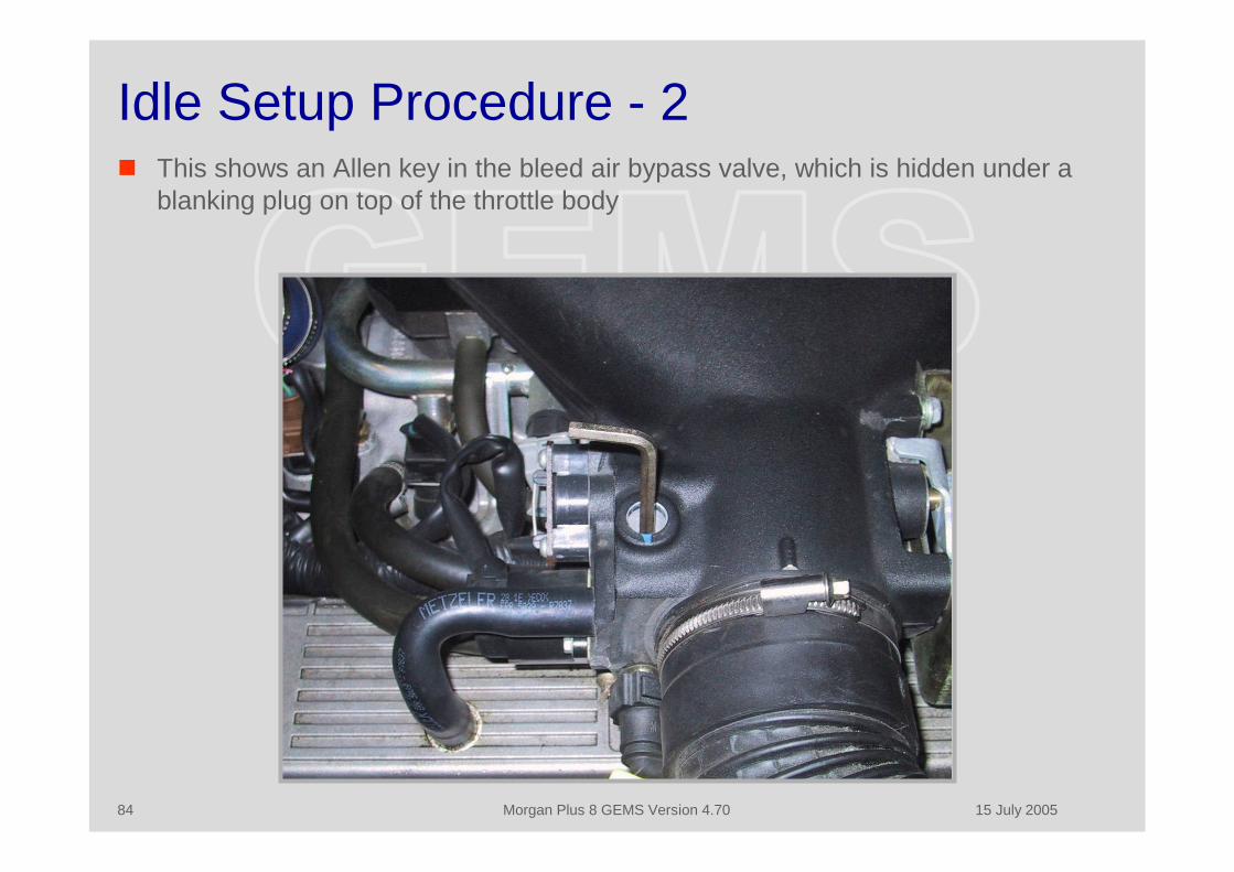
Idle Setup Procedure - 2 This shows an Allen key in the bleed air bypass valve, which is hidden under a
blanking plug on top of the throttle body
15 July 2005Morgan Plus 8 GEMS Version 4.7085
Idle Setup Procedure - 3 If you do not have access to a Rovacom the bleed air valve can be adjusted using
an empirical procedure, but final IACV setting can not be determined precisely The procedure is to open the bleed air bypass valve until the RPM just start to
increase, and the screw the valve in by 1 ¼ turns It is difficult to judge the exact point at which the RPM start to increase, and some
care should be taken to ensure that it is accurately known This procedure is based on the fact that when the RPM start to increase the IACV
will be fully closed, and this represents a known datum for the adjustment
15 July 2005Morgan Plus 8 GEMS Version 4.7086
Lucas 10AS Reset Procedure When
The 10AS should be reset if the GEMS “Security Learn” procedure fails to work, or ifother anomalies occur in the operation. Late model EU cars have this system set toauto-arm, and this can prove annoying. This procedure will disable the auto-arm andset the system to the NAS specifications.
Why The 10AS is a complex system with many sophisticated features, and it can be used in
combination with four different ECMs. Although system settings are stored in non-volatile ROM it is possible for the system to be mis-configured during servicing.
How Select “Restore the Default setting” on the “Other” page of the 10AS menu. Select the data page Set “GEMS” as the ECM type on the lower part of the page. Set the other values to those shown on the example pages titled Lucas 10AS Security
Module 1 & 2 up to (and including the ‘Vehicle Type” setting. Perform the GEMS “Security Learn” procedure.

15 July 2005Morgan Plus 8 GEMS Version 4.7087
10AS Add PLIP Procedure When
You need to add a new PLIP or relearn an existing one following a PLIP battery change. Why
The 10AS can earn up to four PLIPS, and each one will have a different code. ThePLIPS are LUCAS 17TN, but this part number has been used for a variety of differentinternal modules, from TXA through to TXD. They are available in four differentfrequencies, as follows: 224.5 MHz FRANCE 315.0 MHz REST OF THE WORLD (including ITALY, AUSTRALIA, JAPAN, US) 418.0 MHz CANADA, UK-IRELAND (changed to 433.9mhz after 1995) 433.9 MHz EUROPE (not France or Italy)
The frequency is not shown on the outside of the PLIP (usually) but if you open it upyou can see a small metal canister (round on earlier version, square on laterones). This is part of a Surface Acoustic Wave (SAW) oscillator circuit, and you can tellthe frequency from the part number. The round cans have part numbers 1239 for315MHz. and 1207 for 433.92 MHz, and the square cans have part numbers 2704 for315 MHz 2701 for 433.92 MHz.
How Select the “PLIP Programming (Learn) Mode” on the 10AS “Other” menu and then
press the PLIP “repeatedly” until either the relay clicks or the LED flashes (it is meant tobe the hazards but they are not connected on the Plus 8).

15 July 2005Morgan Plus 8 GEMS Version 4.7088
RovacomLite
15 July 2005Morgan Plus 8 GEMS Version 4.7089
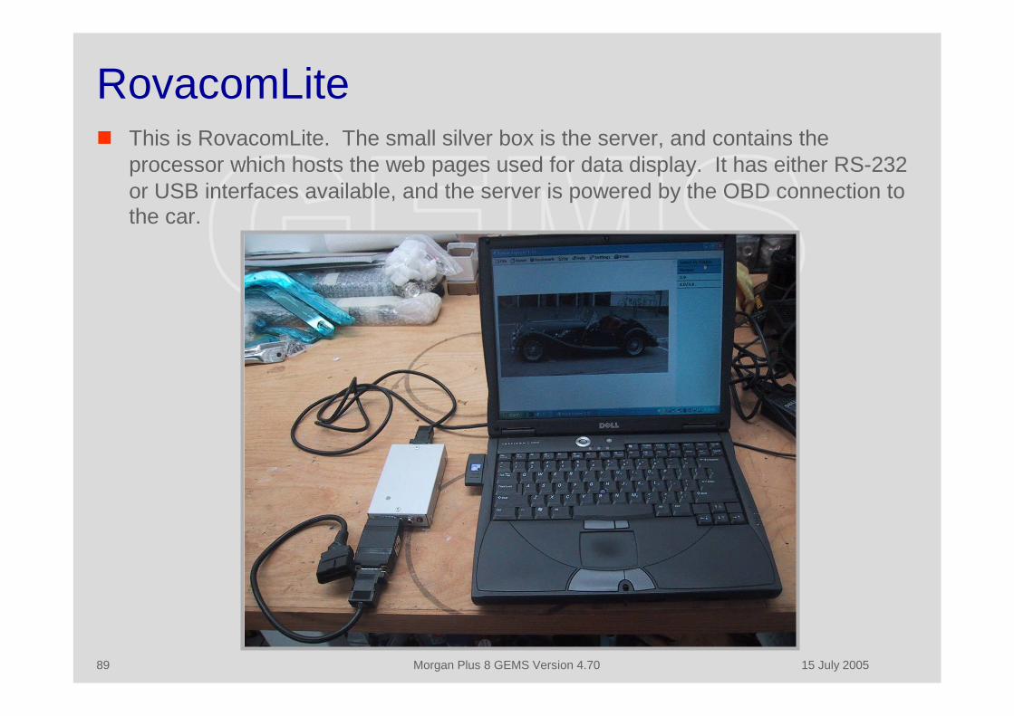
RovacomLite This is RovacomLite. The small silver box is the server, and contains the
processor which hosts the web pages used for data display. It has either RS-232or USB interfaces available, and the server is powered by the OBD connection tothe car.

15 July 2005Morgan Plus 8 GEMS Version 4.7090
RovacomLite Menus This is the introduction screen for Rovacom Lite. There are many modules available which
cover all the different Land Rover and Rover ECM and Security System variants

15 July 2005Morgan Plus 8 GEMS Version 4.7091
Read Data This screen shows the main setup information and adaptive settings that can be read from
the ECM This data can be saved and/or modified and re-written
15 July 2005Morgan Plus 8 GEMS Version 4.7092
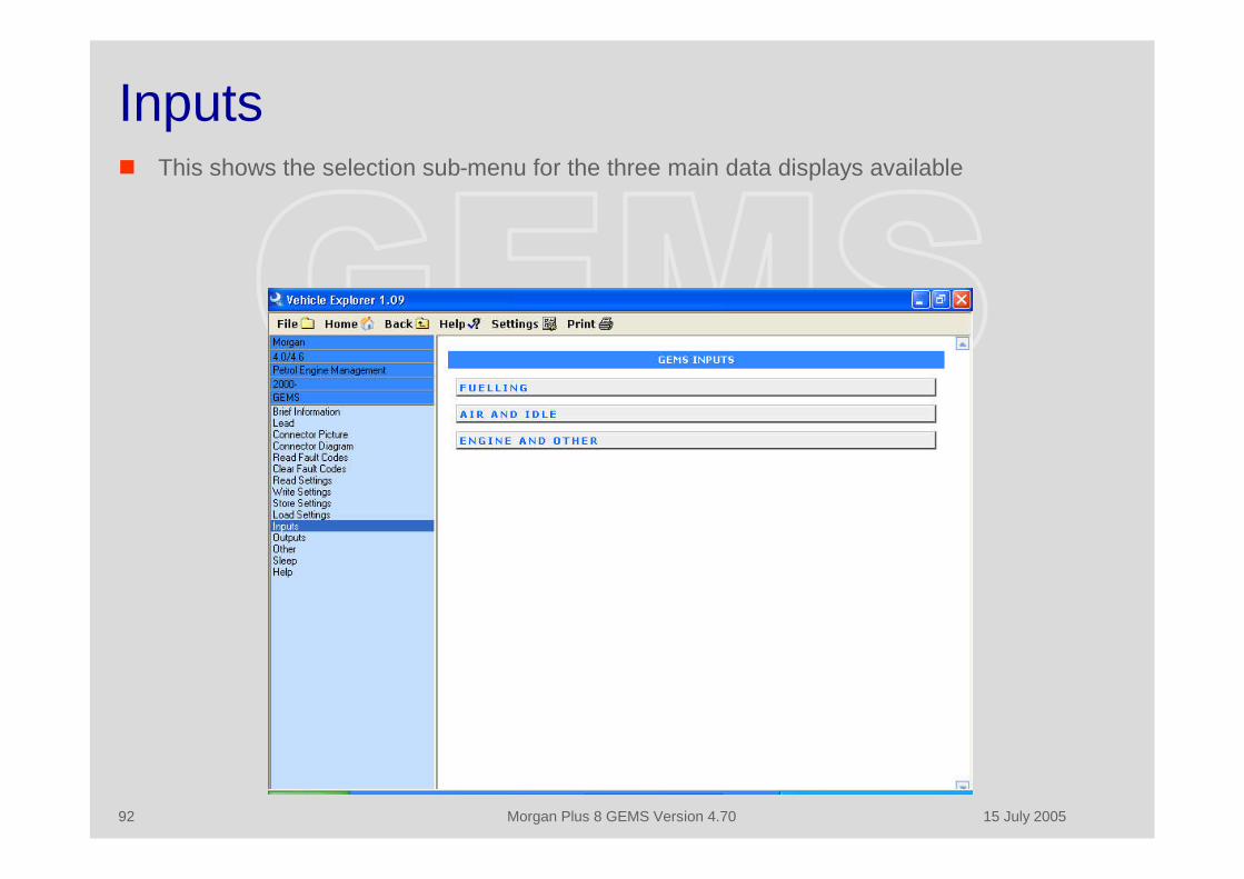
Inputs This shows the selection sub-menu for the three main data displays available
15 July 2005Morgan Plus 8 GEMS Version 4.7093
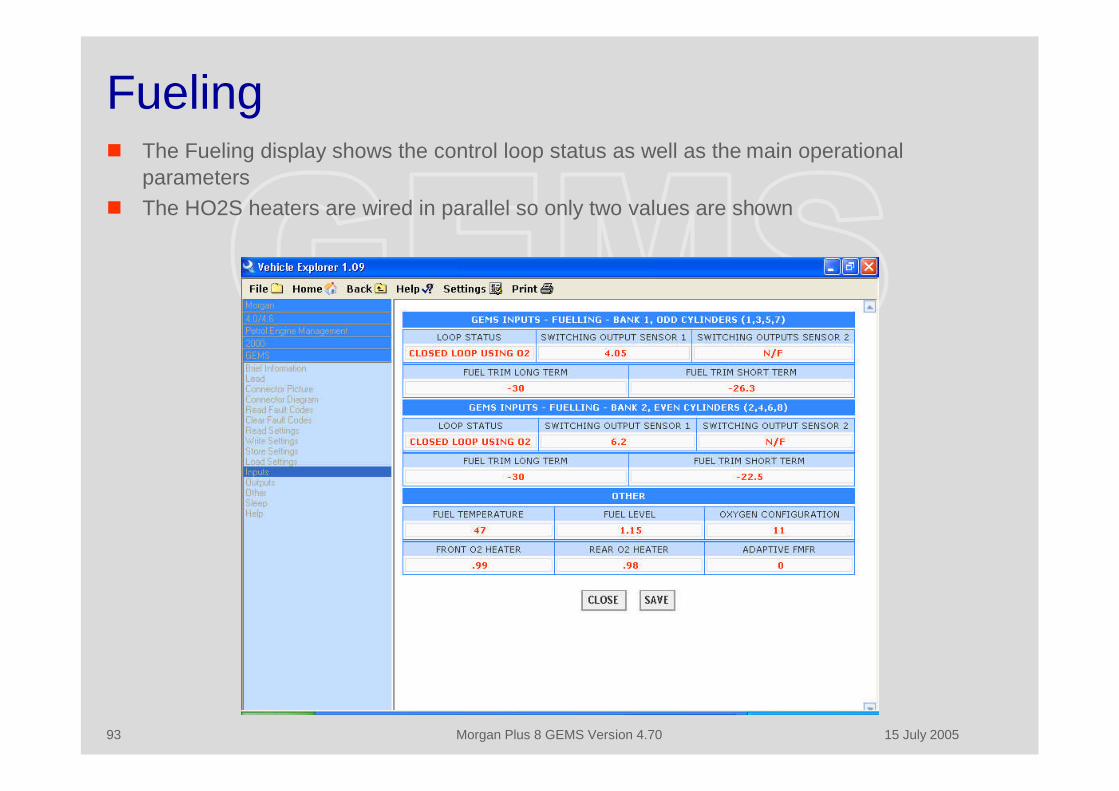
Fueling The Fueling display shows the control loop status as well as the main operational
parameters The HO2S heaters are wired in parallel so only two values are shown
15 July 2005Morgan Plus 8 GEMS Version 4.7094
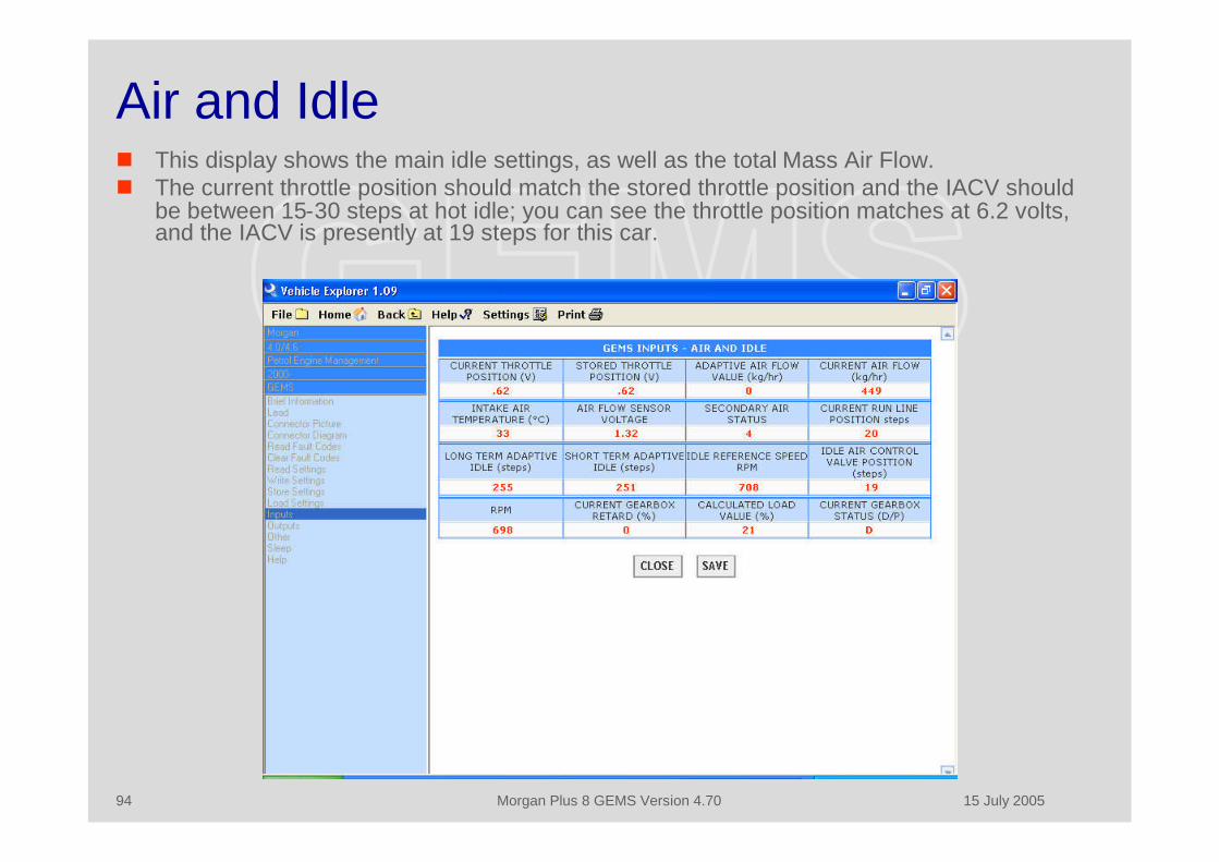
Air and Idle This display shows the main idle settings, as well as the total Mass Air Flow. The current throttle position should match the stored throttle position and the IACV should
be between 15-30 steps at hot idle; you can see the throttle position matches at 6.2 volts,and the IACV is presently at 19 steps for this car.
15 July 2005Morgan Plus 8 GEMS Version 4.7095
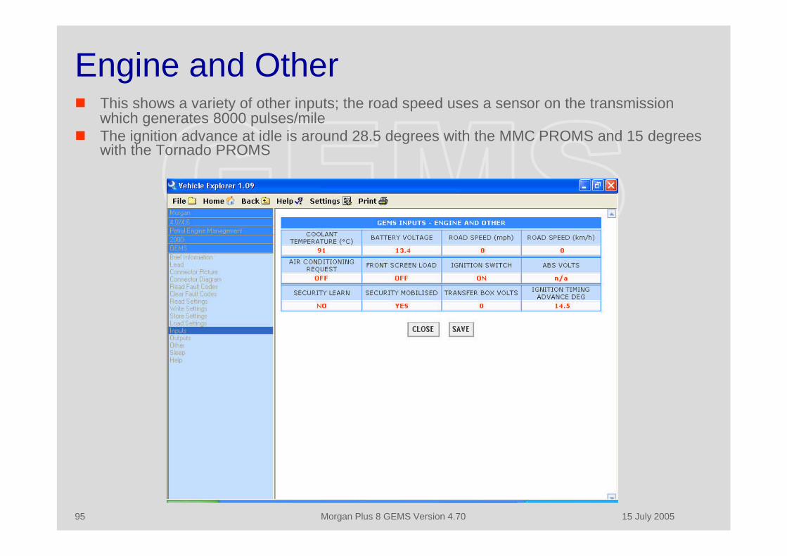
Engine and Other This shows a variety of other inputs; the road speed uses a sensor on the transmission
which generates 8000 pulses/mile The ignition advance at idle is around 28.5 degrees with the MMC PROMS and 15 degrees
with the Tornado PROMS
15 July 2005Morgan Plus 8 GEMS Version 4.7096
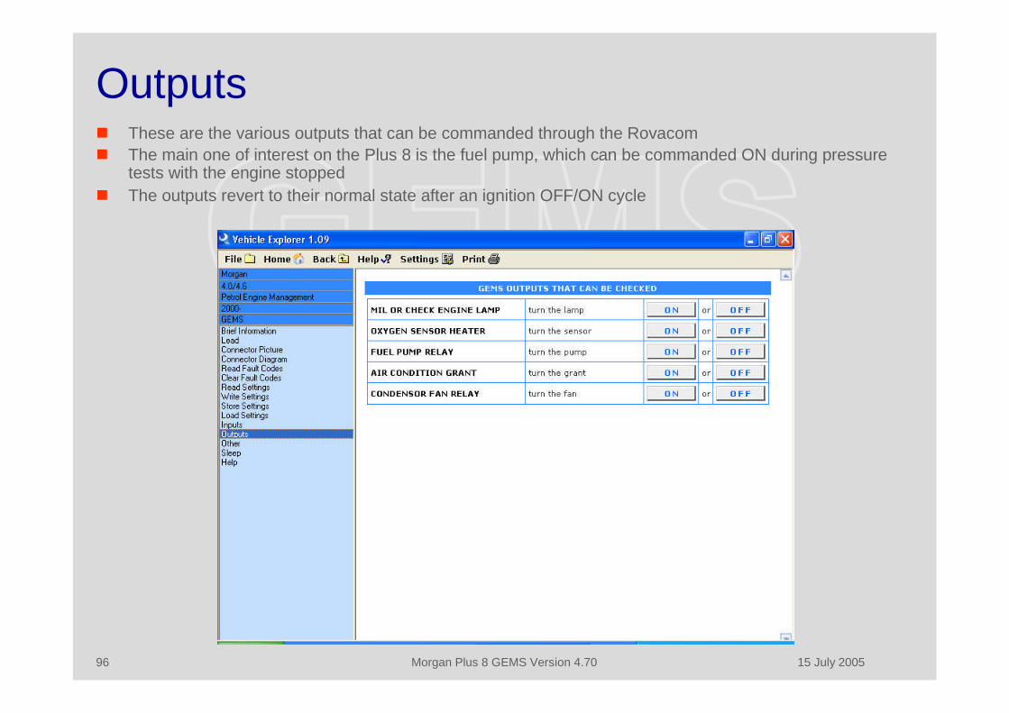
Outputs These are the various outputs that can be commanded through the Rovacom The main one of interest on the Plus 8 is the fuel pump, which can be commanded ON during pressure
tests with the engine stopped The outputs revert to their normal state after an ignition OFF/ON cycle

15 July 2005Morgan Plus 8 GEMS Version 4.7097
Other This page shows the Security Learn and Adaptive Reset Commands There is also a “server reset” command (for the Rovacom server) on the LR menu

15 July 2005Morgan Plus 8 GEMS Version 4.7098
Lucas 10AS Security Module - 1 This screen shows the top half of the default settings for the NAS Morgan Plus 8 in the
Lucas 10AS Security System. There is a clock in the PLIP and the 10AS, which is used tosynchronize the units. If the PLIP is unreliable in operation it is probably because the clocksynchronization settings are wrong.

15 July 2005Morgan Plus 8 GEMS Version 4.7099
Lucas 10AS Security Module - 2 This is the lower half of the default settings for the Morgan. If there are problems with 10AS
operation the system should be initialized to the default settings on the “Other” screen , andthen the Morgan defaults set, including setting the immoboliser type to GEMS. The GEMS“Security Learns” procedure must then be carried out.

15 July 2005Morgan Plus 8 GEMS Version 4.70100
Autotap

15 July 2005Morgan Plus 8 GEMS Version 4.70101
Autotap Autotap is one of the many generic OBD diagnostic tools available. It is similar to
RovacomLite in that it is hosted on a laptop, but it does not use a remote serverand the applications runs on the PC.
The advantage of Autotap is that it can log engine data in real time, and theresultant data files can then be exported to a spreadsheet for analysis.
A diagnostic tool such as Autotap is required for general GEMS maintenancesince RovacomLite cannot access the OBD Monitors used by the EmissionControl tests for post 1995 vehicles. The tests require that all the OBDM (exceptfor a maximum of one) must be set to “Complete”, that the “Check Engine” lightworks and that it is OFF, and that there are no DTC’s for the vehicle to pass.
The data rate through the OBD interface depends on the number of parametersselected, so that for reasonable real time performance during full throttleoperations only two or three parameters should be selected simultaneously.
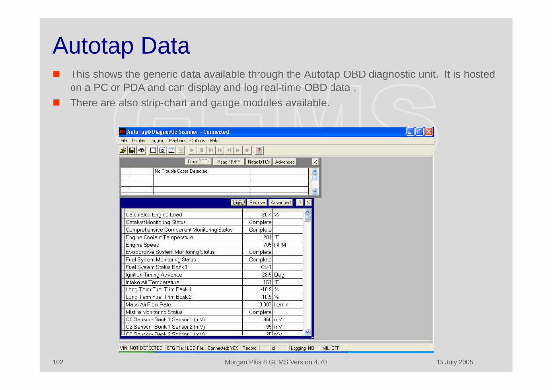
15 July 2005Morgan Plus 8 GEMS Version 4.70102
Autotap Data This shows the generic data available through the Autotap OBD diagnostic unit. It is hosted
on a PC or PDA and can display and log real-time OBD data . There are also strip-chart and gauge modules available.

15 July 2005Morgan Plus 8 GEMS Version 4.70103
OBDM This shows the OBD monitors used in the Plus 8 MMC PROMS, and which have to be
complete in order to pass the US emissions tests The OBD Requirements data shows that the car is certified for sale in California
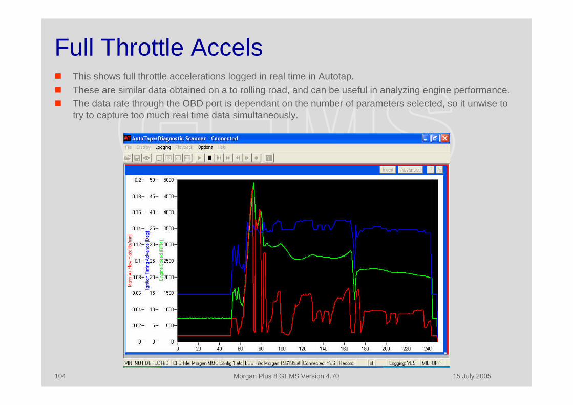
15 July 2005Morgan Plus 8 GEMS Version 4.70104
Full Throttle Accels This shows full throttle accelerations logged in real time in Autotap. These are similar data obtained on a to rolling road, and can be useful in analyzing engine performance. The data rate through the OBD port is dependant on the number of parameters selected, so it unwise to
try to capture too much real time data simultaneously.

15 July 2005Morgan Plus 8 GEMS Version 4.70105
OBD Generic Trouble Codes
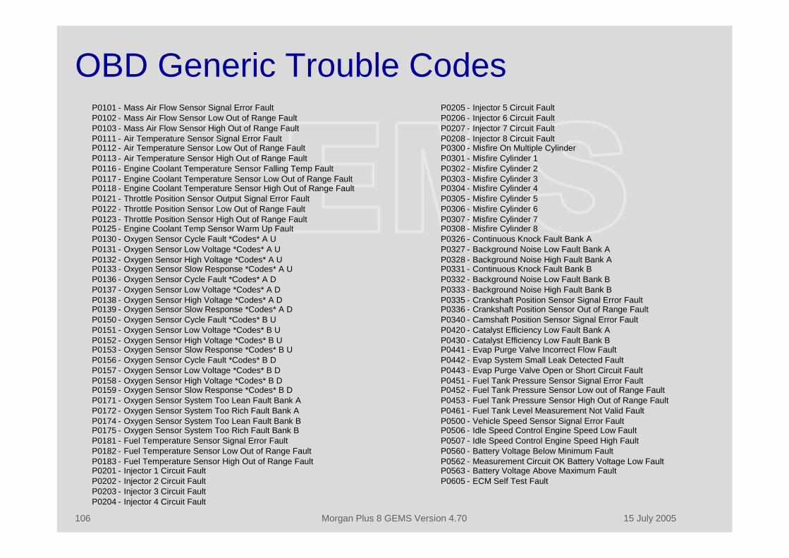
15 July 2005Morgan Plus 8 GEMS Version 4.70106
P0205 - Injector 5 Circuit FaultP0206 - Injector 6 Circuit FaultP0207 - Injector 7 Circuit FaultP0208 - Injector 8 Circuit FaultP0300 - Misfire On Multiple CylinderP0301 - Misfire Cylinder 1P0302 - Misfire Cylinder 2P0303 - Misfire Cylinder 3P0304 - Misfire Cylinder 4P0305 - Misfire Cylinder 5P0306 - Misfire Cylinder 6P0307 - Misfire Cylinder 7P0308 - Misfire Cylinder 8P0326 - Continuous Knock Fault Bank AP0327 - Background Noise Low Fault Bank AP0328 - Background Noise High Fault Bank AP0331 - Continuous Knock Fault Bank BP0332 - Background Noise Low Fault Bank BP0333 - Background Noise High Fault Bank BP0335 - Crankshaft Position Sensor Signal Error FaultP0336 - Crankshaft Position Sensor Out of Range FaultP0340 - Camshaft Position Sensor Signal Error FaultP0420 - Catalyst Efficiency Low Fault Bank AP0430 - Catalyst Efficiency Low Fault Bank BP0441 - Evap Purge Valve Incorrect Flow FaultP0442 - Evap System Small Leak Detected FaultP0443 - Evap Purge Valve Open or Short Circuit FaultP0451 - Fuel Tank Pressure Sensor Signal Error FaultP0452 - Fuel Tank Pressure Sensor Low out of Range FaultP0453 - Fuel Tank Pressure Sensor High Out of Range FaultP0461 - Fuel Tank Level Measurement Not Valid FaultP0500 - Vehicle Speed Sensor Signal Error FaultP0506 - Idle Speed Control Engine Speed Low FaultP0507 - Idle Speed Control Engine Speed High FaultP0560 - Battery Voltage Below Minimum FaultP0562 - Measurement Circuit OK Battery Voltage Low FaultP0563 - Battery Voltage Above Maximum FaultP0605 - ECM Self Test Fault
P0101 - Mass Air Flow Sensor Signal Error FaultP0102 - Mass Air Flow Sensor Low Out of Range FaultP0103 - Mass Air Flow Sensor High Out of Range FaultP0111 - Air Temperature Sensor Signal Error FaultP0112 - Air Temperature Sensor Low Out of Range FaultP0113 - Air Temperature Sensor High Out of Range FaultP0116 - Engine Coolant Temperature Sensor Falling Temp FaultP0117 - Engine Coolant Temperature Sensor Low Out of Range FaultP0118 - Engine Coolant Temperature Sensor High Out of Range FaultP0121 - Throttle Position Sensor Output Signal Error FaultP0122 - Throttle Position Sensor Low Out of Range FaultP0123 - Throttle Position Sensor High Out of Range FaultP0125 - Engine Coolant Temp Sensor Warm Up FaultP0130 - Oxygen Sensor Cycle Fault *Codes* A UP0131 - Oxygen Sensor Low Voltage *Codes* A UP0132 - Oxygen Sensor High Voltage *Codes* A UP0133 - Oxygen Sensor Slow Response *Codes* A UP0136 - Oxygen Sensor Cycle Fault *Codes* A DP0137 - Oxygen Sensor Low Voltage *Codes* A DP0138 - Oxygen Sensor High Voltage *Codes* A DP0139 - Oxygen Sensor Slow Response *Codes* A DP0150 - Oxygen Sensor Cycle Fault *Codes* B UP0151 - Oxygen Sensor Low Voltage *Codes* B UP0152 - Oxygen Sensor High Voltage *Codes* B UP0153 - Oxygen Sensor Slow Response *Codes* B UP0156 - Oxygen Sensor Cycle Fault *Codes* B DP0157 - Oxygen Sensor Low Voltage *Codes* B DP0158 - Oxygen Sensor High Voltage *Codes* B DP0159 - Oxygen Sensor Slow Response *Codes* B DP0171 - Oxygen Sensor System Too Lean Fault Bank AP0172 - Oxygen Sensor System Too Rich Fault Bank AP0174 - Oxygen Sensor System Too Lean Fault Bank BP0175 - Oxygen Sensor System Too Rich Fault Bank BP0181 - Fuel Temperature Sensor Signal Error FaultP0182 - Fuel Temperature Sensor Low Out of Range FaultP0183 - Fuel Temperature Sensor High Out of Range FaultP0201 - Injector 1 Circuit FaultP0202 - Injector 2 Circuit FaultP0203 - Injector 3 Circuit FaultP0204 - Injector 4 Circuit Fault
OBD Generic Trouble Codes

15 July 2005Morgan Plus 8 GEMS Version 4.70107
GEMS-Specific Trouble Codes
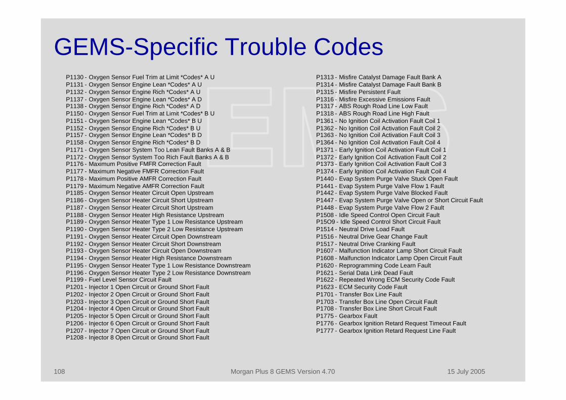
15 July 2005Morgan Plus 8 GEMS Version 4.70108
GEMS-Specific Trouble CodesP1313 - Misfire Catalyst Damage Fault Bank AP1314 - Misfire Catalyst Damage Fault Bank BP1315 - Misfire Persistent FaultP1316 - Misfire Excessive Emissions FaultP1317 - ABS Rough Road Line Low FaultP1318 - ABS Rough Road Line High FaultP1361 - No Ignition Coil Activation Fault Coil 1P1362 - No Ignition Coil Activation Fault Coil 2P1363 - No Ignition Coil Activation Fault Coil 3P1364 - No Ignition Coil Activation Fault Coil 4P1371 - Early Ignition Coil Activation Fault Coil 1P1372 - Early Ignition Coil Activation Fault Coil 2P1373 - Early Ignition Coil Activation Fault Coil 3P1374 - Early Ignition Coil Activation Fault Coil 4P1440 - Evap System Purge Valve Stuck Open FaultP1441 - Evap System Purge Valve Flow 1 FaultP1442 - Evap System Purge Valve Blocked FaultP1447 - Evap System Purge Valve Open or Short Circuit FaultP1448 - Evap System Purge Valve Flow 2 FaultP1508 - Idle Speed Control Open Circuit FaultP15O9 - Idle Speed Control Short Circuit FaultP1514 - Neutral Drive Load FaultP1516 - Neutral Drive Gear Change FaultP1517 - Neutral Drive Cranking FaultP1607 - Malfunction Indicator Lamp Short Circuit FaultP1608 - Malfunction Indicator Lamp Open Circuit FaultP1620 - Reprogramming Code Learn FaultP1621 - Serial Data Link Dead FaultP1622 - Repeated Wrong ECM Security Code FaultP1623 - ECM Security Code FaultP1701 - Transfer Box Line FaultP1703 - Transfer Box Line Open Circuit FaultP1708 - Transfer Box Line Short Circuit FaultP1775 - Gearbox FaultP1776 - Gearbox Ignition Retard Request Timeout FaultP1777 - Gearbox Ignition Retard Request Line Fault
P1130 - Oxygen Sensor Fuel Trim at Limit *Codes* A UP1131 - Oxygen Sensor Engine Lean *Codes* A UP1132 - Oxygen Sensor Engine Rich *Codes* A UP1137 - Oxygen Sensor Engine Lean *Codes* A DP1138 - Oxygen Sensor Engine Rich *Codes* A DP1150 - Oxygen Sensor Fuel Trim at Limit *Codes* B UP1151 - Oxygen Sensor Engine Lean *Codes* B UP1152 - Oxygen Sensor Engine Rich *Codes* B UP1157 - Oxygen Sensor Engine Lean *Codes* B DP1158 - Oxygen Sensor Engine Rich *Codes* B DP1171 - Oxygen Sensor System Too Lean Fault Banks A & BP1172 - Oxygen Sensor System Too Rich Fault Banks A & BP1176 - Maximum Positive FMFR Correction FaultP1177 - Maximum Negative FMFR Correction FaultP1178 - Maximum Positive AMFR Correction FaultP1179 - Maximum Negative AMFR Correction FaultP1185 - Oxygen Sensor Heater Circuit Open UpstreamP1186 - Oxygen Sensor Heater Circuit Short UpstreamP1187 - Oxygen Sensor Heater Circuit Short UpstreamP1188 - Oxygen Sensor Heater High Resistance UpstreamP1189 - Oxygen Sensor Heater Type 1 Low Resistance UpstreamP1190 - Oxygen Sensor Heater Type 2 Low Resistance UpstreamP1191 - Oxygen Sensor Heater Circuit Open DownstreamP1192 - Oxygen Sensor Heater Circuit Short DownstreamP1193 - Oxygen Sensor Heater Circuit Open DownstreamP1194 - Oxygen Sensor Heater High Resistance DownstreamP1195 - Oxygen Sensor Heater Type 1 Low Resistance DownstreamP1196 - Oxygen Sensor Heater Type 2 Low Resistance DownstreamP1199 - Fuel Level Sensor Circuit FaultP1201 - Injector 1 Open Circuit or Ground Short FaultP1202 - Injector 2 Open Circuit or Ground Short FaultP1203 - Injector 3 Open Circuit or Ground Short FaultP1204 - Injector 4 Open Circuit or Ground Short FaultP1205 - Injector 5 Open Circuit or Ground Short FaultP1206 - Injector 6 Open Circuit or Ground Short FaultP1207 - Injector 7 Open Circuit or Ground Short FaultP1208 - Injector 8 Open Circuit or Ground Short Fault

15 July 2005Morgan Plus 8 GEMS Version 4.70109
Copyright and Disclaimers• This material may be distributed freely but may not be altered or sold for gain. It is copyrighted by David A. Poole
(2004, 2005).• The data and material in this document has been obtained from a number of sources including:
• Land Rover and Rover workshop manuals.• Rovacom documentation.• A variety of web sources in the public domain.• Analysis of system operation.• The cover photograph was obtained from the Morgan Motor Company press site.
• This material is provided for the use in the maintenance of the GEMS system. David Poole does not warrant orassume any legal liability or responsibility for the accuracy, completeness, or usefulness of any information,apparatus, product, or process disclosed.
• Please contact me if you have any editorial inputs, additional material, questions or suggestions at:
David A. Poole974 Coachway Drive,Annapolis,Maryland 21401United States of America
T: 410.849.2882F: 410.849.3192M: [email protected]