eng664 computer analytical tools b -...
TRANSCRIPT

Finite Element Assignment
1
ENG664 Computer Analytical Tools B
Amador Calvo, Koldo Aparicio, Rodrigo Folgueira
Lecturer: Dr. Richard Grant
Date: 19 November 2010

Finite Element Assignment
2
INDEX
1. - Summary 3
2. - Tools 6
2.1. - Abaqus
2.2. - MDSolid 3.5
2.3. - HP Calculator
2.4. - Excel
3. - Material 8
4. - Theory 9
4.1.- Theory about beams
4.2.- Theory about “Finite Element Method”
5. - Methodology 10
6. - Results 11
6.1. - Results with Abacus
6.1.1.- C3D8 results
6.1.2.- C3D8I results
6.1.3.- C3D8R results
6.1.4.- C3D20 results
6.1.5.- C3D20R results
6.2. - Results with MDSolid 32
6.3. - Results with HP Calculator
7. - Conclusions 38
8. - References 39

Finite Element Assignment
3
8.1. - Internet
8.2. - Books

Finite Element Assignment
4
1. - SUMMARY
The present report consists in the analysis of a simply supported beam using
the finite element method.
The purpose of this project is to design a supported beam with concrete
specifications like a concentrated load and uniformly distributed loads. The beam is
designed in Abaqus 6.10-1. Finally the aim of the project is to study how the forces
acts in the beam that we are studying and compare the results that we obtain in 3D
with the Abaqus between that we obtain in 2D. For obtain this results in 2D we are
going to use the MD Solid 3.5 program.
For being completely sure that the solution is correct we have used another
tool to calculate the structure, an HP Calculator.
It is also necessary to try different element types like the solid elements to
obtain the most close reality results, for it we will use different kinds of noded bricks,
noded quadrilaterals, and using also different density meshes for being approach to
the most efficient result in our case.
Finally the most important part of the project is to see the different results that
we have obtain and to make some conclusions about them, some graphics made on
Microsoft Excel program have helped us in this proposition because the results are
more visual and clear in this graphics.

Finite Element Assignment
5
2. - Tools
Some tools have been used for making this report; most of them for calculate
the forces of the beam, and other ones to compare the final results. Here there is a
small summary of them:
2.1) Abaqus
For making this project it has been used
Abaqus that is a suite of software applications for
finite element analysis and computer-aided
engineering. Concretely the 6.10-1 version.
Abaqus contains an extensive library of
elements that can model virtually any geometry. It
has an equally extensive list of material models
that can simulate the behavior of most typical
engineering materials including metals, rubber,
polymers, composites, reinforced concrete, crushable and resilient foams, and
geotechnical materials. Abaqus can be used to study more than just structural
problems; it can simulate problems in such diverse areas as heat transfer, mass
diffusion, thermal management of electrical components and piezoelectric analysis.
Abaqus is simple to use even though it offers the user a wide range of
capabilities. The most complicated problems can be modeled easily. For example,
problems with multiple components are modeled by associating the geometry
defining each component with the appropriate material models.
Finite Element Assignment
6
2.2) MDSolid 3.5
MDSolid 3.5 is a program for elasticity
and resistance of materials of easy managing, It
possesses a simple and intuitive interface,
between whose possibilities are twist, Mohr's
circles, calculation of reactions in beams, Laws of
Efforts, etc.
2.3) Graphical calculator HP 50g
HP Calculators the last thing in graphical
calculators for professionals and students of
topography, engineering, mathematics and
sciences is even better. The new graphical
calculator has HP Solve, structured
programming and algebraic system for computer
(CAS).
2.4) Excel
Microsoft Excel is a spreadsheet
application. It features calculation, graphing tools,
pivot tables and a macro programming language
called Visual Basic for Applications. It has been a
very widely applied spreadsheet for these
platforms.

Finite Element Assignment
7
3.- Material
The beam in study is an Aluminum alloy 7075 beam; this alloy is one of the
alloy with more raised characteristics inside the aluminiums. The development of this
alloy has made possible his utilization fields till now reserved to the stils.
It is applied in armament, aeronautics and in the industry of the car.
Construction of machinery, molds for injection of plastic, molds of blown, molds for
extrusion of plastic, supports for all kinds of molds, screws, molds for injected of
rubbers, etc.
Wrought aluminium alloy composition limits (% weight)
Alloy Si Fe Cu Mn Mg Cr Zn V Ti Bi Ga Pb ZR
Limits
Al Each Total
7075 0.40 0.50 1.2-2.0 0.30 2.1-2.9 0.18-0.28 5.1-6.1 0.20 0.05 0.15 remainder

Finite Element Assignment
8
4.- Theory
4.1.- Theory about beams:
A beam is a structural element capable of supporting the load principally by
resisting bending.
It is called the force of bending in the material of the beam to all those
external loads, as the own weigh, the span and external reactions to these loads is
called “bending moment”.
Beams generally are vertical gravitational forces but can also be used
horizontal loads.
The beams are characterized by their profile, their length and their material.
Beams generally carry vertical gravitational forces but can also be used to
carry horizontal loads. The loads carried by a beam are transferred to columns, walls,
or girders, which then transfer the force to adjacent structural compression members.
In light frame construction the joists rest on the beam.

Finite Element Assignment
9
The primary tool for structural analysis of beams is the Euler–Bernoulli beam
equation. Other mathematical methods for determining the deflection of beams
include "method of virtual work" and the "slope deflection method". Engineers are
interested in determining deflections because the beam may be in direct contact with
a brittle material such as glass. Beam deflections are also minimized for aesthetic
reasons. A visibly sagging beam, even if structurally safe, is unsightly and to be
avoided. A stiffer beam (high modulus of elasticity and high second moment of area)
produces less deflection.
Mathematical methods for determining the beam forces (internal forces of the
beam and the forces that are imposed on the beam support) include the "moment
distribution method", the force or flexibility method and the direct stiffness method.
4.2.- Theory about “Finite Element Method”:
The finite element method (FEM) (its practical application often known as
finite element analysis (FEA)) is a numerical technique for finding approximate
solutions of partial differential equations (PDE) as well as of integral equations. The
solution approach is based either on eliminating the differential equation completely
(steady state problems), or rendering the PDE into an approximating system of
ordinary differential equations, which are then numerically integrated using standard
techniques such as Euler's method, Runge-Kutta, etc.
In solving partial differential equations, the primary challenge is to create an
equation that approximates the equation to be studied, but is numerically stable,
meaning that errors in the input and intermediate calculations do not accumulate and
cause the resulting output to be meaningless. There are many ways of doing this, all
with advantages and disadvantages. The Finite Element Method is a good choice for
solving partial differential equations over complicated domains (like cars and oil
pipelines), when the domain changes (as during a solid state reaction with a moving
boundary), when the desired precision varies over the entire domain, or when the
solution lacks smoothness. For instance, in a frontal crash simulation it is possible to
Finite Element Assignment
10
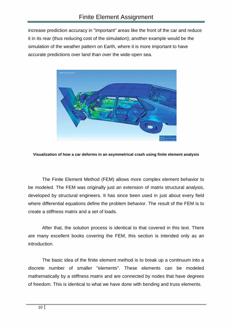
increase prediction accuracy in "important" areas like the front of the car and reduce
it in its rear (thus reducing cost of the simulation); another example would be the
simulation of the weather pattern on Earth, where it is more important to have
accurate predictions over land than over the wide-open sea.
Visualization of how a car deforms in an asymmetrical crash using finite element analysis
The Finite Element Method (FEM) allows more complex element behavior to
be modeled. The FEM was originally just an extension of matrix structural analysis,
developed by structural engineers. It has since been used in just about every field
where differential equations define the problem behavior. The result of the FEM is to
create a stiffness matrix and a set of loads.
After that, the solution process is identical to that covered in this text. There
are many excellent books covering the FEM, this section is intended only as an
introduction.
The basic idea of the finite element method is to break up a continuum into a
discrete number of smaller "elements". These elements can be modeled
mathematically by a stiffness matrix and are connected by nodes that have degrees
of freedom. This is identical to what we have done with bending and truss elements.

Finite Element Assignment
11
However, beams and trusses have natural locations at which to define nodes.
In addition, the derivation of their stiffness matrices can be done on a physical basis.
Simple FEM Theory
More general finite elements require slightly more complicated procedures
than used for beams in order to derive the stiffness matrix. The basic procedure is to
assume a shape function that describes how the nodal displacements are distributed
throughout the element based. From the differential equation, we form an operator
matrix that will convert the displacements within the element into strains. Next the
internal and external virtual work can be formed and equated to develop the stiffness
matrix.
The last step is identical to that used for truss and bending elements.

Finite Element Assignment
12
5. - Methodology
Before starting to define the beam, all of the units must be put in the same unit
because all input data is specified in consistent units. This table shows some of the
most common systems of consistent units and is that is has been used in this
project:
This image
represents the labeling
convention used for the
displacement and
rotational degrees of
freedom in Abaqus.
Finite Element Assignment
13
This is the convention that has been used in this project for deciding what is
the best option to choose the correct supports of the beam.
In this case the best solution in the left (for de fixed support), has been to bear
in mind that U1 and U2 are equal zero and in the right (for the rolled support) only
the U2 is equal zero.
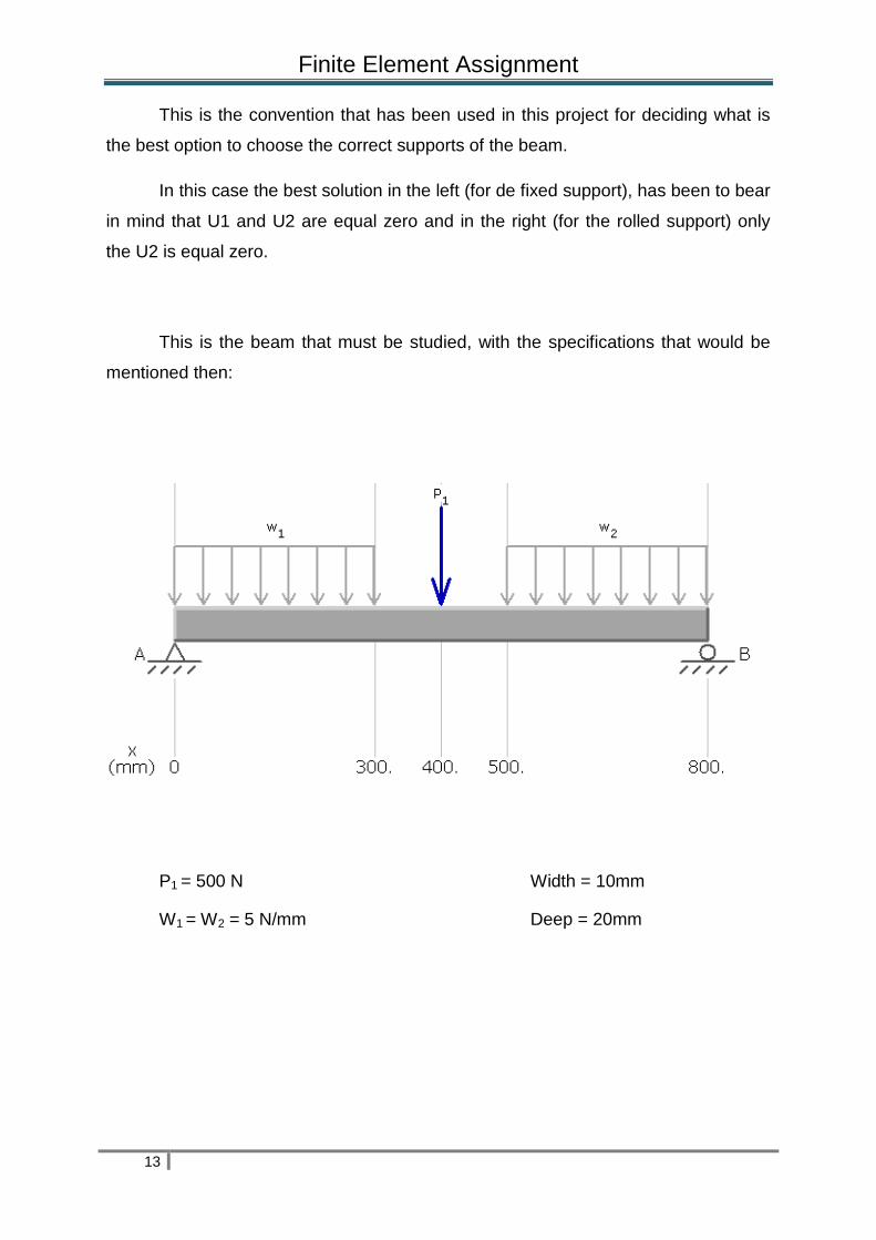
This is the beam that must be studied, with the specifications that would be
mentioned then:
P1 = 500 N Width = 10mm
W1 = W2 = 5 N/mm Deep = 20mm

Finite Element Assignment
14
First it is indispensable to get all input data in consistent units, how we explain
before. It is an 3D program so it is necessary to transform the N/mm into N/mm2
(MPa).
The operation is that:
= 0, 25 MPa
When all is defined, is the time to start working with Abaqus. We think this
work must not be a catalogue of the individual commands you have used to set up
and solve the problem so we only include images or steps that we judge to
important. First the beam must be defined with the forces and the boundary
conditions.
Finite Element Assignment
15
Then it is necessary to create the steps, the mesh, and running the job.
The second part consist in get the results and study them, for this is
necessary to obtain more results with other tools like MDSolid and in our case with a
calculator.
The last part is to compare these results and to obtain the conclusions about
the study of them, for this it is possible to use some graphics that have been made in
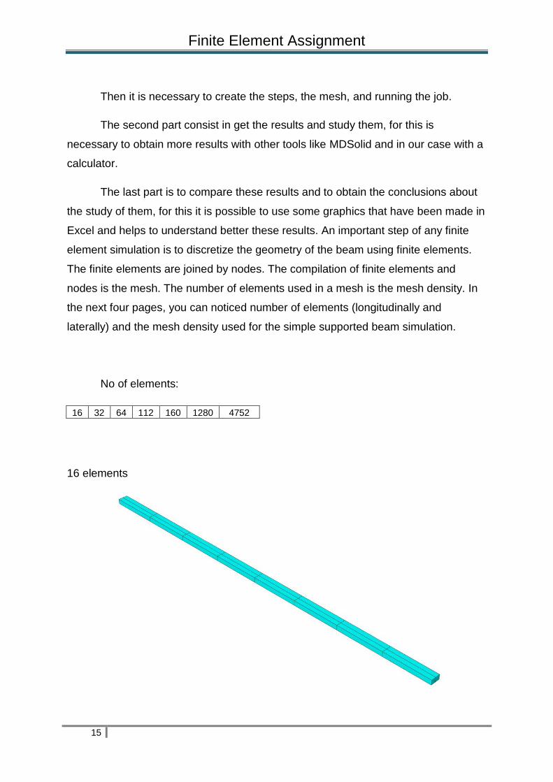
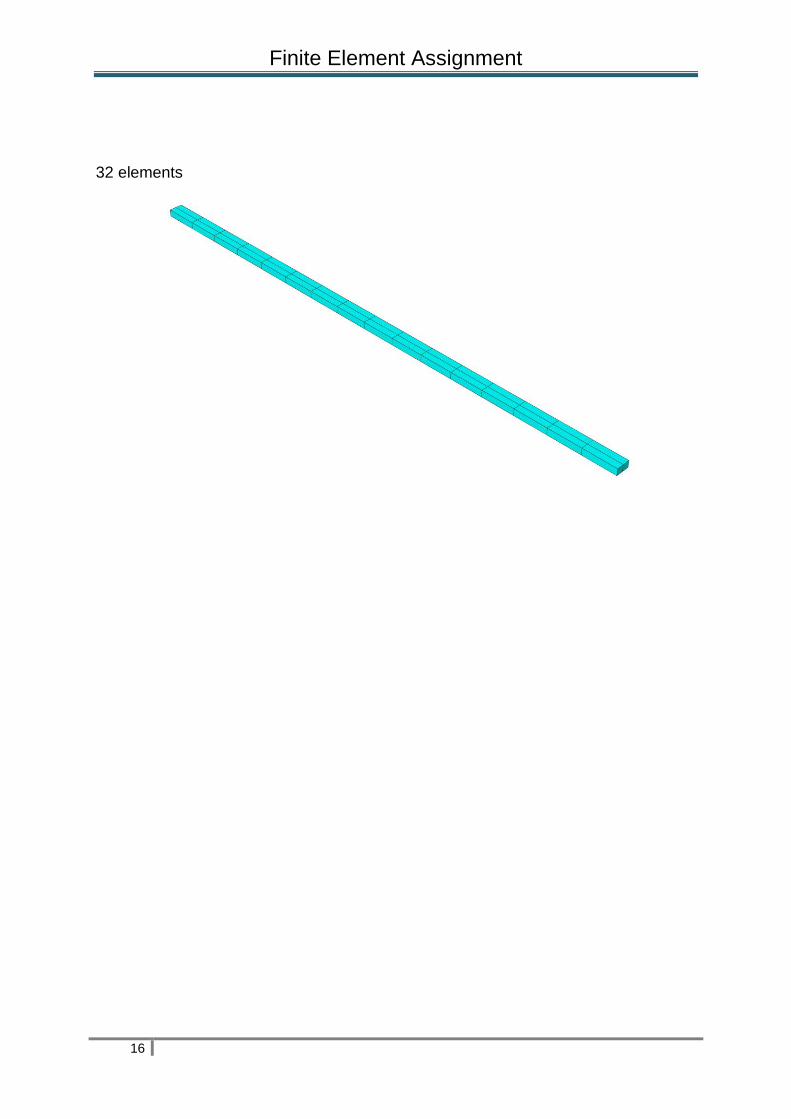
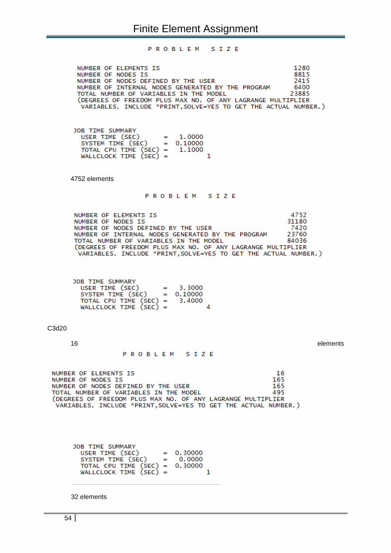
Excel and helps to understand better these results. An important step of any finite
element simulation is to discretize the geometry of the beam using finite elements.
The finite elements are joined by nodes. The compilation of finite elements and
nodes is the mesh. The number of elements used in a mesh is the mesh density. In
the next four pages, you can noticed number of elements (longitudinally and
laterally) and the mesh density used for the simple supported beam simulation.
No of elements:
16 32 64 112 160 1280 4752
16 elements
Finite Element Assignment
16
32 elements

Finite Element Assignment
17
64 elements
112 elements

Finite Element Assignment
18
160 elements
1280 elements
Finite Element Assignment
19
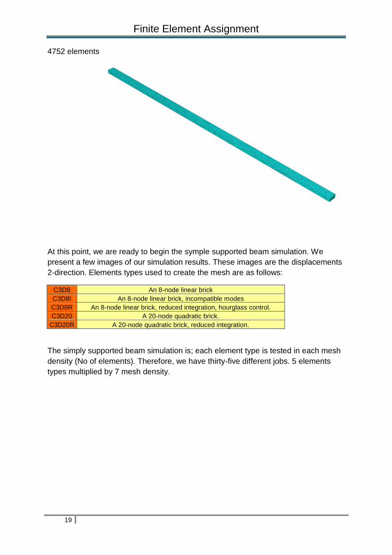
4752 elements
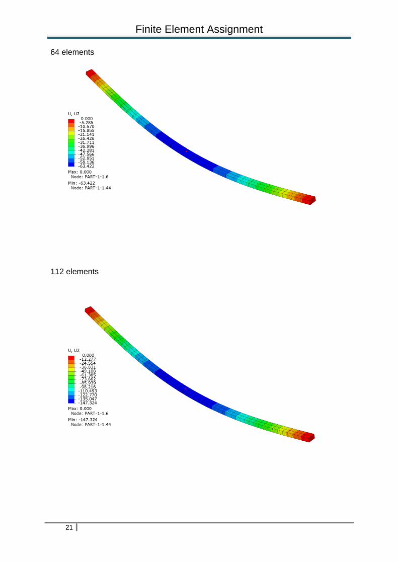
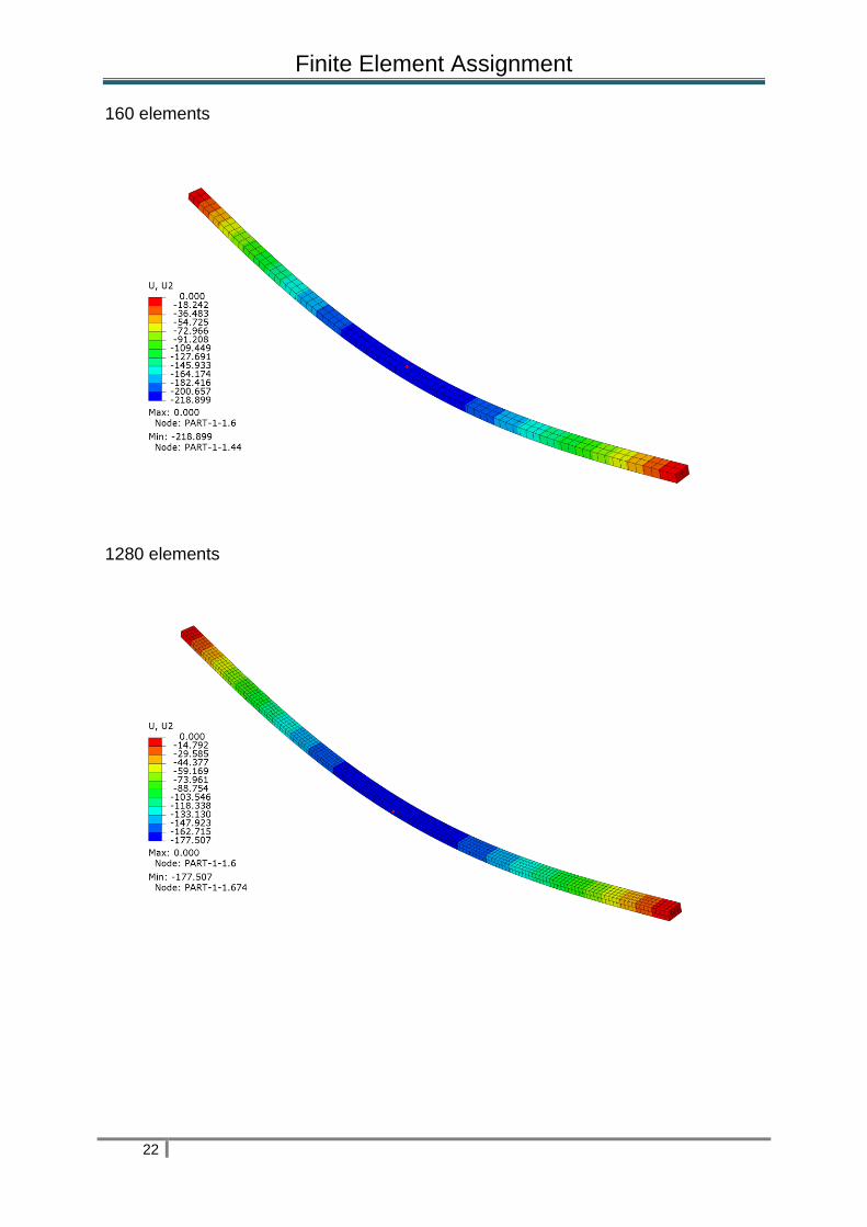
At this point, we are ready to begin the symple supported beam simulation. We
present a few images of our simulation results. These images are the displacements
2-direction. Elements types used to create the mesh are as follows:
C3D8 An 8-node linear brick
C3D8I An 8-node linear brick, incompatible modes
C3D8R An 8-node linear brick, reduced integration, hourglass control.
C3D20 A 20-node quadratic brick.
C3D20R A 20-node quadratic brick, reduced integration.
The simply supported beam simulation is; each element type is tested in each mesh
density (No of elements). Therefore, we have thirty-five different jobs. 5 elements
types multiplied by 7 mesh density.

Finite Element Assignment
20
6. - Results
6.1. - Abaqus Results:
6.1.1.- C3D8 results:
16 elements
32 elements
Finite Element Assignment
21
64 elements
112 elements
Finite Element Assignment
22
160 elements
1280 elements

Finite Element Assignment
23
4752 elements
The table shows displacements in 2-direction. Element type C3D8.

Finite Element Assignment
24
6.1.2.- C3D8I results:
16 elements
32 elements
64 elements
Finite Element Assignment
25
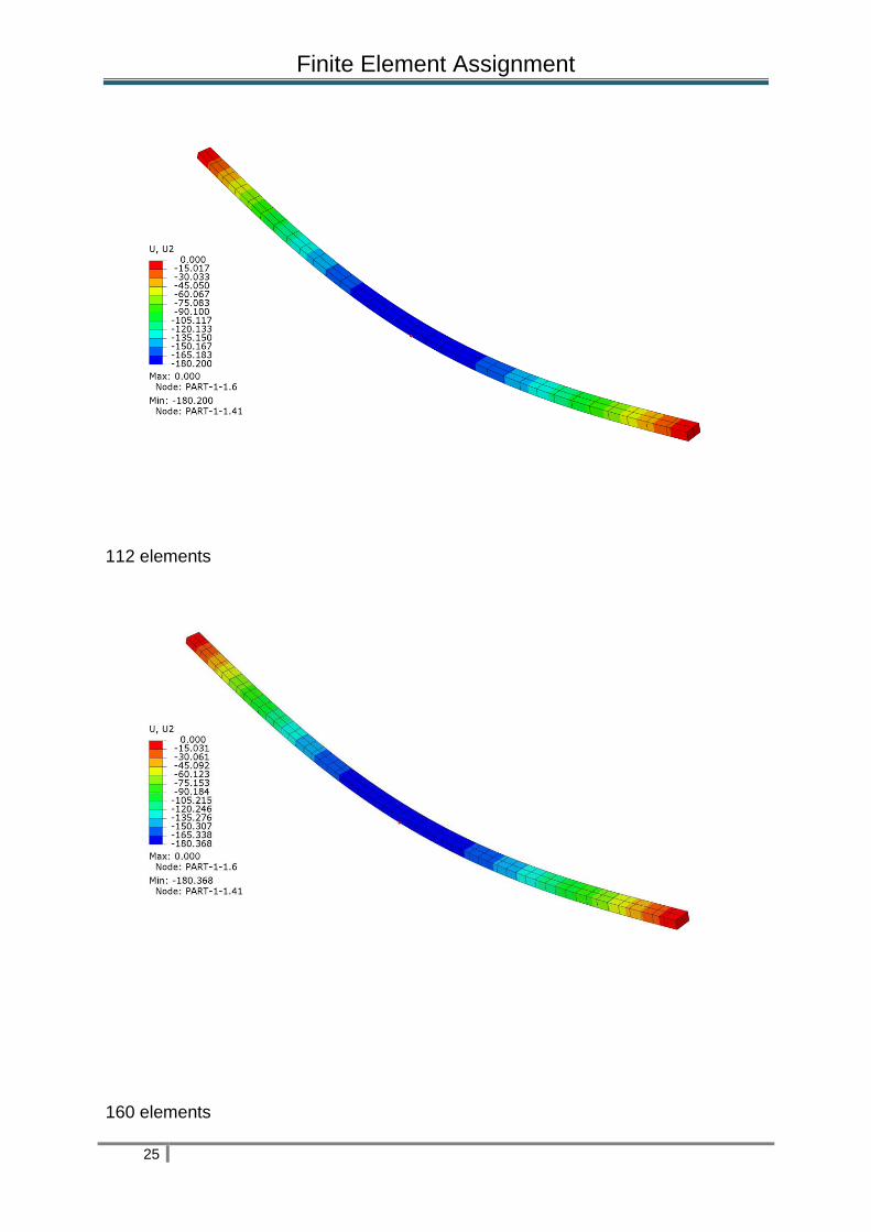
112 elements
160 elements

Finite Element Assignment
26
1280 elements
4752 elements

Finite Element Assignment
27
Displacements in 2-direction are shown in this table. Element type C3D8I

Finite Element Assignment
28
6.1.3.- C3D8R results:
16 elements
32 elements

Finite Element Assignment
29
64 elements
112 elements
Finite Element Assignment
30
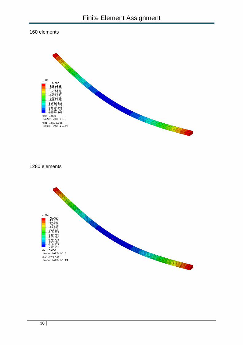
160 elements
1280 elements

Finite Element Assignment
31
4752 elements
The table, reproduced below, shows the displacements in 2-direction. Element type C3D8R.

Finite Element Assignment
32
6.1.4.- C3D20 results :
16 elements
32 elements

Finite Element Assignment
33
64 elements
112 elements

Finite Element Assignment
34
160 elements
1280 elements

Finite Element Assignment
35
4752 elements
This table shows the displacement in 2-direction. Element type C3D20

Finite Element Assignment
36
6.1.5.- C3D20R results :
16 elements
32 elements
Finite Element Assignment
37
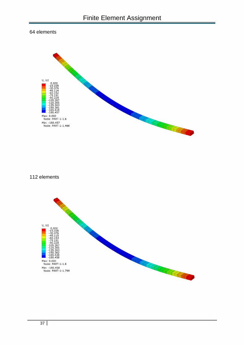
64 elements
112 elements
Finite Element Assignment
38
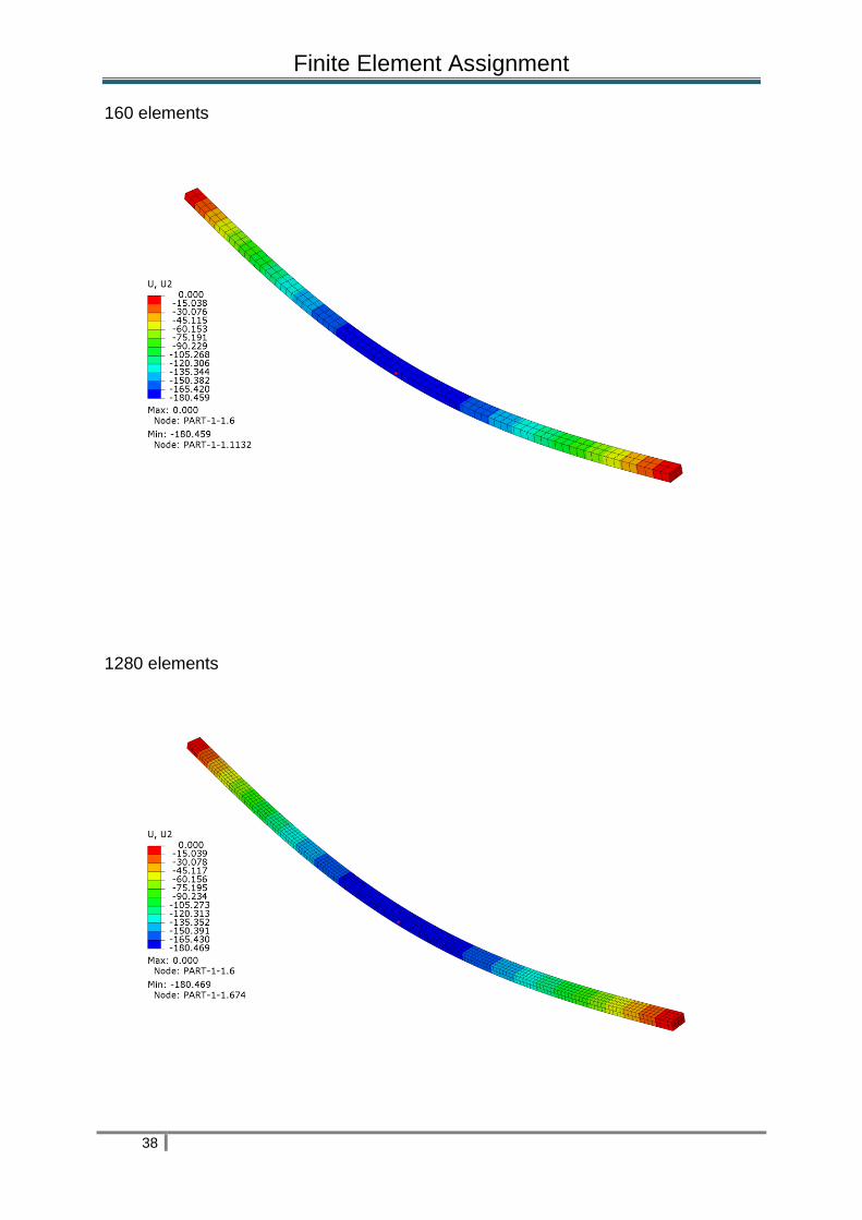
160 elements
1280 elements
Finite Element Assignment
39
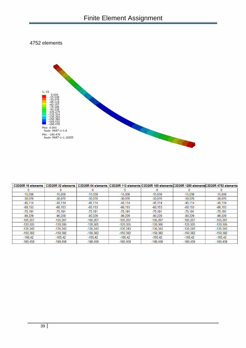
4752 elements

Finite Element Assignment
40
6.2. - Results with MDSolid 32

Finite Element Assignment
41
The diagram, shows below, are indicated the theory value of 180.382 mm in 2-direction (U2).
Finite Element Assignment
42
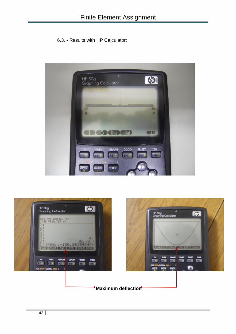
6.3. - Results with HP Calculator:
Maximum deflection
Finite Element Assignment
43
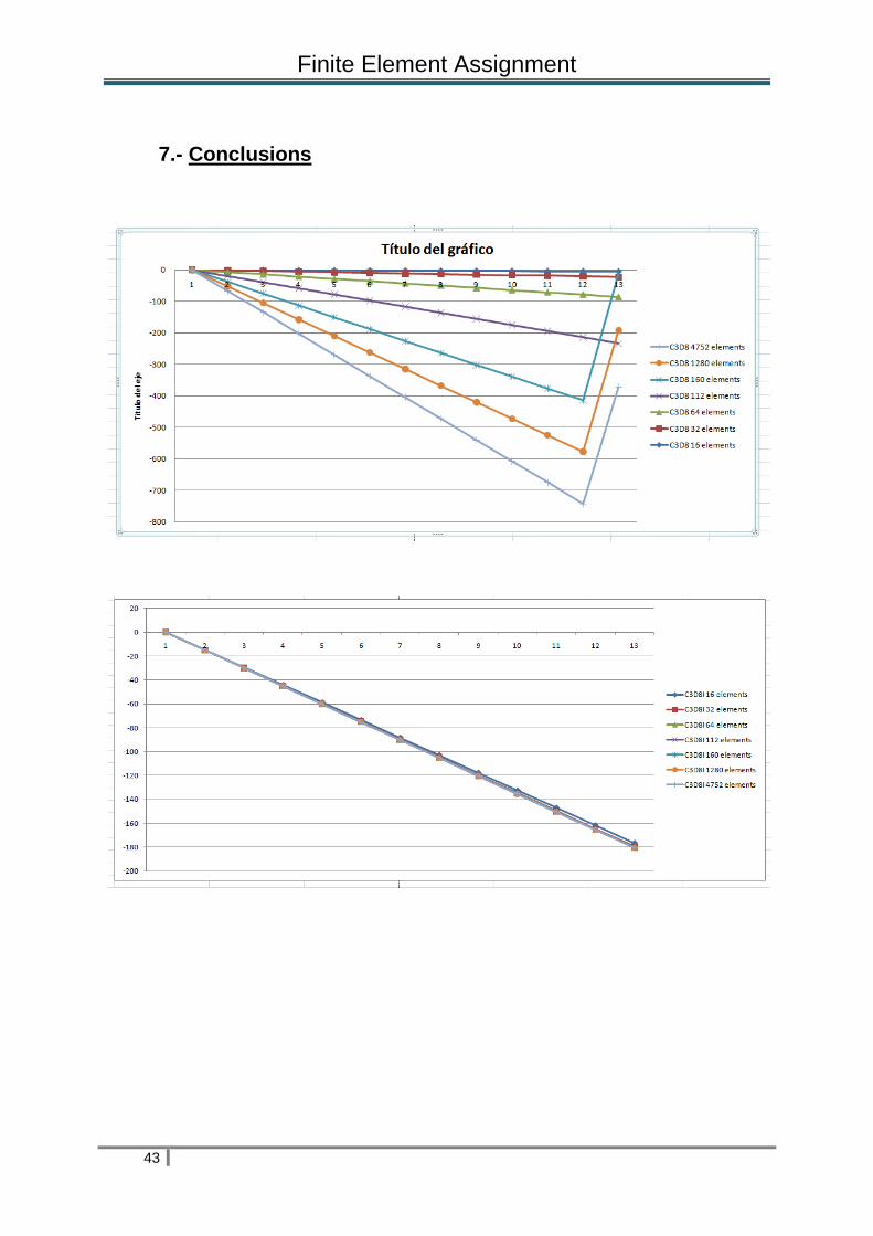
7.- Conclusions

Finite Element Assignment
44
Finite Element Assignment
45

Finite Element Assignment
46
Different finite element meshes have been used in simply supported beam
simulation. We have used in our work linear and quadratic elements, fully and
reduced integration and incompatible modes. The correct choice of element is very
important if you want to obtain accurate results at a low cost. It is necessary that we
use a sufficiently refined mesh to ensure correct results in our simulation. Little fine
mesh (not many elements) can lead to poor results. When you increase the mesh
density your numerical solution will go toward a single value, however your computer
needs much time for running a job and consequently your work goes down. These
ideas are suggested in the following book; Getting started with Abaqus/Standar,
Interactive version, chapter 4, page 37. We are going to check these ideas are
according our work and select one element type for simply supported beam
simulation.
We round up the theory value of 180.382 mm to 180.4 mm since the error produced
is ridiculous and are sure our results are more comfortable to understand with such
rounding.
With these considerations we are ready to discuss our results. First, we put the
results in tables and graphs and then discuss them,
The table, reproduced below, shows maximum displacements in 2-direction.
No of elements
Element type 16 32 64 112 160 1280 4752
C3D8 -4,6 -17,9 -63,4 -147,3 -218,9 -177,5 -179,8
C3D8I -176,4 -179,4 -180,2 -180,4 -180,4 -180,4 -180,4
C3D8R -16.230,50 -16.493,80 -16.559,70 -16.574,50 -16.578,20 -239,7 -202,7
C3D20 -178 -180 -180,4 -180,4 -180,4 -180,4 -180,4
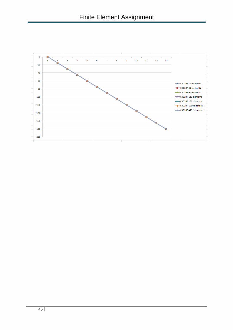
C3D20R -180,4 -180,4 -180,4 -180,4 -180,4 -180,4 -180,4

Finite Element Assignment
47
The ratios of the maximum displacements for the simply supported beam simulation to the theory value of 180.4
mm are shown below.
No of elements
Element type 16 32 64 112 160 1280 4752
C3D8 0,02549889
1 0,09922394
7 0,351441242 0,81651884
7 1,21341463
4 0,98392461
2 0,99667405
8
C3D8I 0,97782705
1 0,99445676
3 0,998891353 1 1 1 1
C3D8R 89,97 91,43 91,79 91,88 91,90 1,32871396
9 1,12361419
1
C3D20 0,98669623
1 0,99778270
5 1 1 1 1 1
C3D20R 1 1 1 1 1 1 1
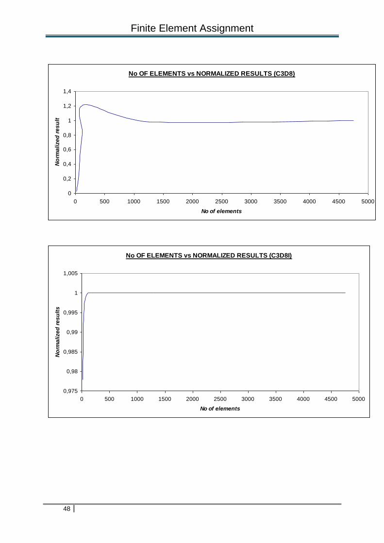
Depends on the choice of your element type, the results vary greatly. First element
type, C3D8 in our conclusions, produce inaccurate results when the mesh density is
low until 160 elements. With 64 elements predicts a maximum displacement that is
only 35.1% of the theoretical value. With 160 elements we think of anything that we
can not explain; the value calculated is 21% more than theory value of 180.4 mm. At
the beginning, we thought our simulation was wrong but we made it again and the
result was the same. When the mesh density is increased the results are close to the
theory value. 98.39 % with 1280 elements and 99.66 % with 4752 elements.
C3D8I element, second here, predicts accurate results with 16, 32 and 64 elements
about 99% of theoretical value. From 112 elements the results are exact. Therefore,
C3D8I is a behavior that fits with the discussion in the first paragraph that is to say
when the mesh density increases your numerical solution will go toward a single
value.
C3D8R predicts the deflection so badly that the results are very poor. Until 160
elements the results are about 90 times more than in theory. From 1280 elements
the results improve a lot, however they are not accurate. 1280 elements 1.32 times
more and 4752 elements 1.12 times more. With this element type is demonstrated is
shown the number of elements is vital if you want to obtain accurate results.
C3D20 only underpredict the deflection 2 mm with 16 elements. With 32 elements
predicts a maximum displacement in 2-direction of 99.7%. From there the results are
exact.
Finally, C3D20R predicts accurate results from the 16 elements.
Finite Element Assignment
48
No OF ELEMENTS vs NORMALIZED RESULTS (C3D8)
0
0,2
0,4
0,6
0,8
1
1,2
1,4
0 500 1000 1500 2000 2500 3000 3500 4000 4500 5000
No of elements
No
rma
lize
d r
es
ult
No OF ELEMENTS vs NORMALIZED RESULTS (C3D8I)
0,975
0,98
0,985
0,99
0,995
1
1,005
0 500 1000 1500 2000 2500 3000 3500 4000 4500 5000
No of elements
No
rma
lize
d r
es
ult
s

Finite Element Assignment
49
No OF ELEMENTS vs NORMALIZED RESULTS (C3D8I)
0,975
0,98
0,985
0,99
0,995
1
1,005
0 500 1000 1500 2000 2500 3000 3500 4000 4500 5000
No of elements
No
rma
lize
d r
es
ult
s
No OF ELEMENTS vs NORMALIZED RESULTS (C3D20R)
0
0,2
0,4
0,6
0,8
1
1,2
0 500 1000 1500 2000 2500 3000 3500 4000 4500 5000
No of elements
No
rma
lize
d r
es
ult
s

Finite Element Assignment
50
8.- References
8.1.- Internet
Wikipedia:
Technical information about the aluminum alloy:
http://en.wikipedia.org/wiki/7075_aluminium_alloy
http://www.electrocome.com/al7075.htm
Information about Excel program:
http://en.wikipedia.org/wiki/EXCEL
Theory about beams:
http://en.wikipedia.org/wiki/Beam_%28structure%29
Theory about Finite Element:
http://en.wikipedia.org/wiki/Finite_element_method
Description of the MDSolid 32:
http://www.el-hacker.com/md-solids-3-5-calculo-de-estructuras/
Information About the HP Calculator:
http://h41111.www4.hp.com/calculators/es/es/graphing/50g/index.html
Theory about Finite Element:
http://www.ce.ufl.edu/~mih/courses/CES4141/Notes%2062%20-
%20Basic%20Finite%20Element%20Theory.pdf

Finite Element Assignment
51
8.2.- Books
Getting Starter with ABAQUS / Standard (Interactive version)
Hibbitt, Karlson & Sorensen, Inc.

Finite Element Assignment
52
DAT
Datos numéricos del Abaqus
C3d8i
16 elements
32 elements
64 elements

Finite Element Assignment
53
112 elements
160 elements
1280 elements
Finite Element Assignment
54
4752 elements
C3d20
16 elements
32 elements

Finite Element Assignment
55
64 elements
112 elements

Finite Element Assignment
56
160 elements
1280 elements
4752 elements
C3d20r

Finite Element Assignment
57
16 elements
32 elements
64 elements
112 elements

Finite Element Assignment
58
160 elements
1280 elements
4752 elements

Finite Element Assignment
59