energy savings from implementing and commissioning demand...
TRANSCRIPT
COMM-20130501-72625 | July 2015
Energy Savings from Implementing and Commissioning Demand Control
Ventilation
Lessons learned from observed practical approaches
Conservation Applied Research & Development (CARD) FINAL REPORT
Prepared for: Minnesota Department of Commerce, Division of Energy Resources
Prepared by: Seventhwave
Prepared by: Scott Hackel Saranya Gunasingh Ben Auchter Melanie Lord Alisa Petersen
Seventhwave 749 University Row, Suite 320 Madison, WI 53705
Contract Number: 72625
Prepared for Minnesota Department of Commerce, Division of Energy Resources Mike Rothman, Commissioner, Department of Commerce Bill Grant, Deputy Commissioner, Department of Commerce, Division of Energy Resources Mark Garofano, Project Manager 651-539-1864 [email protected]
ACKNOWLEDGEMENTS This project was supported in part (or in whole) by a grant from the Minnesota Department of Commerce, Division of Energy Resources, through the Conservation Applied Research and Development (CARD) program, which is funded by Minnesota ratepayers.
The authors would also like to acknowledge all participating research subjects for their cooperation and time, and Siemens Building Technologies for their technical assistance.
DISCLAIMER This report does not necessarily represent the view(s), opinion(s), or position(s) of the Minnesota Department of Commerce (Commerce), its employees or the State of Minnesota (State). When applicable, the State will evaluate the results of this research for inclusion in Conservation Improvement Program (CIP) portfolios and communicate its recommendations in separate document(s).
Commerce, the State, its employees, contractors, subcontractors, project participants, the organizations listed herein, or any person on behalf of any of the organizations mentioned herein make no warranty, express or implied, with respect to the use of any information, apparatus, method, or process disclosed in this document. Furthermore, the aforementioned parties assume no liability for the information in this report with respect to the use of, or damages resulting from the use of, any information, apparatus, method, or process disclosed in this document; nor does any party represent that the use of this information will not infringe upon privately owned rights.
i
Table of Contents
List of Figures .......................................................................................................................................... iii
List of Tables ............................................................................................................................................ iv
Executive Summary .................................................................................................................................. 1
Background and Objective ................................................................................................................ 1
Results and Conclusions ................................................................................................................... 1
Introduction ............................................................................................................................................... 5
Objective ...................................................................................................................................................... 6
Literature Review ...................................................................................................................................... 7
Research Method ..................................................................................................................................... 10
Introduction .............................................................................................................................................. 10
Discovery and characterization .............................................................................................................. 10
Field Work ................................................................................................................................................. 11
Recommissioning ..................................................................................................................................... 12
Recommissioning Process ............................................................................................................... 13
Occupant Survey .............................................................................................................................. 14
Analysis ..................................................................................................................................................... 15
Data Accuracy................................................................................................................................... 15
Air Handling Unit Energy Balance ................................................................................................ 16
Whole Building Energy Model....................................................................................................... 21
Results ....................................................................................................................................................... 25
Characterization of DCV in Minnesota ................................................................................................. 25
Control Sequences Encountered .................................................................................................... 26
Other Characterizations .................................................................................................................. 28
Energy Usage and Savings Potential ..................................................................................................... 28
Typical Energy Savings ................................................................................................................... 28
Climatic Sensitivity .......................................................................................................................... 34
Savings from Commissioning ........................................................................................................ 34
Check against Energy Models ........................................................................................................ 38
Impact of Code Changes ......................................................................................................................... 39
ii
Occupant Comfort Impacts .................................................................................................................... 41
Occupant Comfort Surveys ............................................................................................................ 42
CO2 Level Measurements ................................................................................................................ 44
Economics of DCV in Minnesota ........................................................................................................... 46
Conclusions and Recommendations ................................................................................................... 49
DCV Systems in Minnesota .................................................................................................................... 49
Viability of CO2 DCV ............................................................................................................................... 49
Indoor Air Quality Impacts ............................................................................................................ 51
Code Implications .................................................................................................................................... 52
Steps to Optimal Implementation of DCV Technology ...................................................................... 53
Design ................................................................................................................................................ 54
Installation (hardware) .................................................................................................................... 59
Controls Programming (and M&V) .............................................................................................. 60
Operation (and occupant behavior) .............................................................................................. 60
Energy Modeling ................................................................................................................................. 63
Commissioning or Recommissioning ........................................................................................... 63
Expanding and Improving CIP Offerings ............................................................................................ 64
Opportunity #1: New DCV systems and system retrofits ......................................................... 64
Opportunity #2: Recommissioning ............................................................................................... 66
Opportunity #3: Ventilation Redesign .......................................................................................... 67
Opportunity #4: More Effective Trade Allies .............................................................................. 68
Example Programs ........................................................................................................................... 68
Further Research Needed ....................................................................................................................... 69
Glossary .................................................................................................................................................... 72
References................................................................................................................................................. 73
Appendix A: Monitoring Installation Checklist ............................................................................... 75
Appendix B: Occupant Satisfaction Survey ....................................................................................... 79
Appendix C: Recommissioning Checklist ......................................................................................... 80
Appendix D: Building Characterization Data Table ........................................................................ 85
iii
List of Figures
Figure 1. Calculation framework for analyzing energy flows in the air handling units monitored. ................................................................................................................................................. 17
Figure 2. Energy savings from DCV is proportional to the two differences shown here, in a sample of data from one day at Library A. .......................................................................................... 18
Figure 3. Example of correlations used to determine energy savings/oF scaling factor in order to weather normalize the data. ................................................................................................................... 20
Figure 4. Characterization of DCV systems identified during the study. N = 98 systems. ........... 25
Figure 5. Typical single setpoint and proportional sequences; the solid lines represent OA flow rate, which are responding to the signal from the CO2 sensor (dashed lines). ............................... 27
Figure 6. Percentage of total air-handling unit energy saved by CO2 DCV. Note that reheat energy was not included in the total energy for this calculation. ..................................................... 29
Figure 7. Percentage of total cost savings, across all six buildings, due to each fuel. .................... 30
Figure 8. Annual energy cost savings per unit of area (per square foot) from values in Table 5. 31
Figure 9. Annual energy cost savings per unit of design outside airflow (in this case, per cubic feet per minute); from values in Table 6. .............................................................................................. 32
Figure 10. Energy cost savings per unit outside airflow ($/cfm) for each system, ........................ 37
Figure 11. Modeled energy savings vs. measured energy savings for three DCV systems: Library B, Office/Art Gallery, and Higher Ed Performing Arts. .................................................................... 39
Figure 12. The impact of adjusting the two older buildings in the study to the new energy code, shown as energy cost per cfm of OA. The baseline (blue) bar is the system operating without DCV; the red bars represent the system operation with DCV. The hatched bar represents DCV operation at new code ventilation rates. ............................................................................................... 41
Figure 13. Responses to the survey question “Please rate your level of satisfaction with the temperature / setpoints in your workspace.” ..................................................................................... 42
Figure 14. Responses to the survey question “Please rate your level of satisfaction with the amount of fresh air in your workspace.” .............................................................................................. 43
Figure 15. The average normalized distance from neutral (comfortable) for all respondents in each of two groups. Zero (0.0) equals a perfectly neutral (comfortable) response, and 1.0 equals the worst response received out of all respondents. ........................................................................... 44
Figure 16. CO2 concentrations measured in individual zones, versus the CO2 concentration measured in the return air just before the air handling unit. ............................................................ 45
Figure 17. Typical raw BAS output for a proportional CO2 sequence in an occupancy event. The red line shows CO2 concentration in ppm for a given zone, and the blue line shows the OA flow to that zone (this is from the office system, with the 100% OA DOAS). .......................................... 61
Figure 18. Typical raw BAS output for a single setpoint CO2 sequence in an occupancy event. 62
iv
Figure 19. Patterns to look for in OA flow data on a BAS to determine whether DCV is working or not working. If only OA damper position data is available, it should look similar, but of course with an axis scaled by percentage (%). ..................................................................................... 67
List of Tables
Table 1. Summary of key energy savings results. ................................................................................. 2
Table 2: Summary of recommissioning energy savings ....................................................................... 2
Table 3. Key characteristics of the six monitored buildings .............................................................. 11
Table 4. The different control sequences encountered in the 98 buildings observed, along with the frequency of use of each sequence. ................................................................................................. 26
Table 5. Annual energy savings per unit of area (per square foot). .................................................. 30
Table 6. Annual energy savings per unit of design outside airflow (in this case, per cubic feet per minute). ..................................................................................................................................................... 32
Table 7. Annual energy savings per unit of design outside airflow (in this case, per cubic feet per minute) for Duluth weather ................................................................................................................... 34
Table 8. System improvements identified for each system during the recommissioning process. .................................................................................................................................................................... 35
Table 9. Annual energy savings per unit of area (per square foot), after recommissioning. ........ 36
Table 10. Annual energy savings per unit of design outside airflow (in this case, per cubic feet per minute), after recommissioning. ..................................................................................................... 36
Table 11. Change in annual energy savings as a result of recommissioning. Savings is given per unit of design outside airflow (in this case, per cubic feet per minute). .......................................... 38
Table 12. Required rates of OA flow required in Minnesota for select spaces, for three different versions of the state mechanical code over time. These spaces represent those found in the six systems we monitored in detail. ............................................................................................................ 40
Table 13. Economic inputs for life cycle cost analysis. ........................................................................ 46
Table 14. Break-even costs, per 1000 cfm of design OA, for installing CO2-based DCV on a VAV system. Typical control is shown in the center, as evidenced by typical results from our study. 47
Table 15. Summary of key energy savings results. ............................................................................. 50
Table 16. Summary of key economic results. ....................................................................................... 51
Table 17. Summary of recommissioning energy savings. .................................................................. 51
Table 18. Selected efficiency programs providing incentives for DCV ............................................ 69
Energy Savings from Commissioning DCV COMM-20130501-72625 | July 2015 Seventhwave 1 | P a g e
Executive Summary
Background and Objective Demand control ventilation (DCV) systems use sensors — generally either CO2 or occupancy sensors — to estimate the actual number of people in an area and supply only as much ventilation air as is needed at a given time. DCV has the potential to save a substantial portion of building energy use in extreme climates like Minnesota and other areas of the northern US. While DCV has been in use for over 20 years and its theoretical impacts well demonstrated, little is known about its operation and energy performance in real buildings. And even less is known about its performance in complex multizone systems.
This project aims to provide information to fill knowledge gaps in: 1) quantifying impacts of DCV implementation in Minnesota, 2) improving existing system operation through commissioning, and 3) general DCV best practices.
Meeting these objectives should create opportunities for implementing DCV in more projects in Minnesota specifically, but also throughout the northern climates of the United States by extension. We focused specifically on multizone, non-packaged systems because they serve a large portion of DCV floor space but are both less understood and substantially more complex than single zone rooftop units.
We began by gathering information on a number of actual DCV systems (spanning 32 buildings) installed in this region. We then selected a subset of six systems and took detailed measurements to analyze their impacts. We collected dozens of data points on each of these systems across all seasons, using a combination of verified building automation system (BAS) data in addition to data from our own instrumentation. Following this initial period of monitoring, we recommissioned the systems according to best practices in order to optimize performance. This two-step approach allowed us to quantify the energy savings of the original systems and then identify increased savings due to commissioning. Additionally, we asked building occupants to complete a comfort survey so we could assess the impact of DCV on occupant comfort. Finally, we collected and tabulated lessons learned from system designers and operators throughout all of these steps.
Results and Conclusions In our initial, broad characterization of DCV in Minnesota, we observed a large variety of approaches to controlling ventilation. The vast majority of systems were of the same type: multizone Variable Air Volume (VAV) systems with economizer control. (Note, again, that we excluded packaged rooftop units.) But the control sequences in these systems varied greatly; most did not appear to follow a single standard practice, let alone best practices. Many designers seem to favor a relatively aggressive approach with a tendency toward direct control of outside air (OA) dampers without consideration for system ventilation efficiency. We found this in 67% of systems. And 19% of systems used a single CO2 sensor in a common return to control all ventilation air.
Energy Savings from Commissioning DCV COMM-20130501-72625 | July 2015 Seventhwave 2 | P a g e
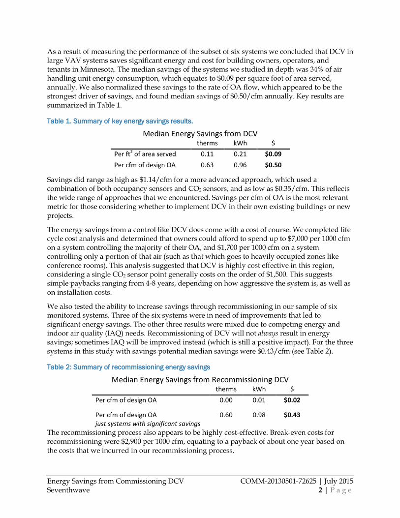
As a result of measuring the performance of the subset of six systems we concluded that DCV in large VAV systems saves significant energy and cost for building owners, operators, and tenants in Minnesota. The median savings of the systems we studied in depth was 34% of air handling unit energy consumption, which equates to $0.09 per square foot of area served, annually. We also normalized these savings to the rate of OA flow, which appeared to be the strongest driver of savings, and found median savings of $0.50/cfm annually. Key results are summarized in Table 1.
Table 1. Summary of key energy savings results.
Median Energy Savings from DCV therms kWh $
Per ft2 of area served 0.11 0.21 $0.09 Per cfm of design OA 0.63 0.96 $0.50
Savings did range as high as $1.14/cfm for a more advanced approach, which used a combination of both occupancy sensors and CO2 sensors, and as low as $0.35/cfm. This reflects the wide range of approaches that we encountered. Savings per cfm of OA is the most relevant metric for those considering whether to implement DCV in their own existing buildings or new projects.
The energy savings from a control like DCV does come with a cost of course. We completed life cycle cost analysis and determined that owners could afford to spend up to $7,000 per 1000 cfm on a system controlling the majority of their OA, and $1,700 per 1000 cfm on a system controlling only a portion of that air (such as that which goes to heavily occupied zones like conference rooms). This analysis suggested that DCV is highly cost effective in this region, considering a single CO2 sensor point generally costs on the order of $1,500. This suggests simple paybacks ranging from 4-8 years, depending on how aggressive the system is, as well as on installation costs.
We also tested the ability to increase savings through recommissioning in our sample of six monitored systems. Three of the six systems were in need of improvements that led to significant energy savings. The other three results were mixed due to competing energy and indoor air quality (IAQ) needs. Recommissioning of DCV will not always result in energy savings; sometimes IAQ will be improved instead (which is still a positive impact). For the three systems in this study with savings potential median savings were $0.43/cfm (see Table 2).
Table 2: Summary of recommissioning energy savings
Median Energy Savings from Recommissioning DCV therms kWh $
Per cfm of design OA 0.00 0.01 $0.02
Per cfm of design OA just systems with significant savings
0.60 0.98 $0.43
The recommissioning process also appears to be highly cost-effective. Break-even costs for recommissioning were $2,900 per 1000 cfm, equating to a payback of about one year based on the costs that we incurred in our recommissioning process.
Energy Savings from Commissioning DCV COMM-20130501-72625 | July 2015 Seventhwave 3 | P a g e
Indoor Air Quality We considered the resulting impacts of DCV on IAQ by measuring zone CO2 levels and conducting occupant comfort surveys. We found that five of the six systems had adequate IAQ. In recommissioning, an adjustment was made to the sixth system (with inadequate IAQ) to increase its OA at certain times. This corrected the IAQ issue, albeit with a penalty to the average energy saved in recommissioning. The one other negative IAQ impact we did find was related to the frequent approach of using a single CO2 sensor in a common return duct. In some cases this practice can lead to inadequate control for IAQ. (See section CO2 Sensor Location for more details on this complex impact.)
On the upside, five of the six buildings that we monitored had the capability through DCV to automatically increase OA to meet IAQ requirements (in addition to the capability to decrease OA for energy savings), yielding more robust IAQ than most non-DCV systems.
Code Implications Results of a code investigation and comparison to our measurements and models showed that, on paper, the new energy code will have very little impact on DCV systems. The actual clause governing DCV does not change with the new code, and required ventilation rates have changed only minimally going back eight years. Much older systems could save energy by upgrading to the new code upon recommissioning; the new code requires much lower OA rates than the older codes. But the new Minnesota energy code may have its biggest impact through a somewhat different mechanism: increased enforcement and compliance. Based on our conversations and observations throughout the study, it is clear that enforcement of DCV in the energy code has been a very low priority in the state — nonexistent in many jurisdictions. With the new code, the state is promoting renewed awareness and training, which could increase compliance.
Steps to Optimal Implementation of DCV Technology Throughout our study, we also compiled significant lessons learned for implementing DCV:
Design. Designers of new VAV systems have one best approach for a DCV sequence, which is the zone and ventilation reset sequence using both zone occupancy sensors and CO2 sensors. In the optimal system, the CO2 setpoint should be set following the specific guidelines in Appendix A of the ASHRAE Standard 62.1 User’s Manual. Lower and upper limits should be thought out and set by the designer; specific details on executing all of these can be found in the body of the report. Finally, we observed that the complexity of DCV also affords designer’s flexibility: DCV is not simply a “yes or no” proposition but should instead be a question of “how much” for the designer.
Sensors. CO2 sensors should be placed in all large or densely occupied zones. Return sensors should be placed as described in CO2 Sensor Location. Occupancy sensors should be used in all smaller or less densely occupied spaces. Finally, airflow should be measured by — and controlled based on — an airflow measurement station laid out in an appropriate position in the mechanical layout drawings.
Energy Savings from Commissioning DCV COMM-20130501-72625 | July 2015 Seventhwave 4 | P a g e
Installation. If the design process is thorough, installation tends to be done correctly. However, we observed that the design is often not complete enough and crucial elements are left to an under-informed contractor. A decision should be made as to who (engineer or contractor) is responsible for design. That individual should produce a thorough design prior to installation, with full understanding of the owner’s requirements. The only other installation problems that were reported involved occupancy sensors that were used for both lighting and airflow control; here careful coordination between these contractors is critical for success.
Operation. We observed substantial room for improvement in the handover from the design and construction team to the operator of the facility. Important elements that should be covered with the operator in this handover include: proper training for adjustment of the sequence, location of CO2 sensors and reporting/alarms, and the reasons for DCV’s importance. Next to proper handover, we found that preventative maintenance to maintain accurate CO2 readings was quite important: 19% of the sensors we observed required calibration during our 15-month study.
Commissioning. In all our efforts, we found that the most critical steps in commissioning of DCV systems were verification of key design elements during design review, calibration of CO2 sensors, verification of OA damper scheduling after occupancy, and a review of OA operation via the BAS for at least a week during occupancy and after initial commissioning. Commissioning steps are described in detail in the Recommissioning Process section of this report and a complete checklist is provided in Appendix C: Recommissioning Checklist.
Expanding and Improving CIP Offerings These results suggest four primary opportunities for expanding and improving DCV Conservation Improvement Program (CIP) offerings in Minnesota.
Opportunity #1: New DCV systems and system retrofits. Due to the economic and energy potential of DCV, existing offerings should be maintained, and every utility could consider additional, or broader, DCV incentives. Both prescriptive and custom offerings could be improved from their existing status in the state. Note that DCV is primarily a heating savings measure, so heating fuel type is important.
Opportunity #2: Recommissioning. Existing DCV systems should be targeted by recommissioning, retrocommissioning, and building tune-up programs, as there is evidence that a significant number of existing systems are not living up to potential. Implementation could follow the checklists we have laid out.
Opportunity #3: Ventilation Redesign. There is substantial savings in recommissioning the OA portion of an air handling system whether DCV is present or not, due to new codes, lack of compliance, high unreasonable safety factors, changes in space use, and improper measurement and control of OA rate. A specific program could be offered for this ‘redesign’ of OA operation.
Opportunity #4: More Effective Trade Allies. Trade allies should receive additional training, primarily in awareness of savings opportunities, design requirements for DCV, as well as in hands-on operation with BASs and CO2 sensors.
Energy Savings from Commissioning DCV COMM-20130501-72625 | July 2015 Seventhwave 5 | P a g e
Introduction Ventilation is a critical component of heating, ventilating, and air conditioning (HVAC) systems; it delivers fresh air to building occupants, maintains building pressurization, provides cooling, and more. In typical commercial spaces like offices, retail stores, and institutional buildings, ventilation and its associated exhaust rids the space of two primary types of indoor pollutants — those from occupants of the building and those that come from furniture and other building components — thus keeping indoor air quality (IAQ) within accepted limits for both the health and comfort of the occupants. Buildings without proper ventilation will have high indoor pollutant concentrations, which can cause adverse health effects (resulting in broad impacts, such as ‘sick building’ syndrome, in some cases). But in conventional HVAC design, the ventilation system must be designed based on the assumption that the building is always at peak occupancy (including significant safety factors). Anecdotally, most systems never even have this peak occupancy due to diversity, and if peak occupancy is reached it is for portions of the day only. Spaces with extreme variation — such as theaters, training rooms, etc. — can be nearly empty for large portions of the year. Whenever any of these spaces are at less than peak (maximum, by code) occupancy, conventional ventilation systems are providing more ventilation than is needed.
Over-ventilation increases heating and cooling loads, as well as fan usage, all of which contribute to increased energy consumption. Much of this energy increase can be saved through demand control ventilation (DCV). DCV systems use sensors — generally either CO2 or occupancy sensors — to estimate the actual number of people in an area and supply only as much ventilation air as is needed by those people at that time. DCV systems have the potential to save a substantial portion of a building’s energy use, especially in extreme climates (cold and humid) like Minnesota. Therefore, they are becoming increasingly common. In fact, the newest energy codes require the technique in more space types.1 Between high performance buildings (with goals to save energy) and those covered under the new energy codes2, thousands of commercial new construction and renovation projects are being implemented across the country each year.
While DCV technology has been in use for some time — it saw some mainstream implementation 20 years ago — it has not been widely implemented until recently due to knowledge gaps, inexperienced project teams, tight timelines and limited budgets. In its years of existence, the theoretical impacts of DCV have been well demonstrated (see the Literature Review section for examples). But little is known about the actual operation and energy performance of these systems in real buildings. The potential for optimizing DCV performance, and the steps required to reach that optimal state, are also only beginning to be understood.
As a result, it’s likely that many DCV systems are operating at less than optimal levels, and that the uncertainly about operational and maintenance issues have posed significant barriers to
1 Anything based on ASHRAE 90.1-2007 or later requires DCV in most spaces with more than 40 people per 1000 ft2, which describes most assembly spaces. 2 The new energy code being the 2015 Minnesota Energy Code, which is to be based on ASHRAE Standard 90.1-2010.
Energy Savings from Commissioning DCV COMM-20130501-72625 | July 2015 Seventhwave 6 | P a g e
market penetration that result in fewer DCV systems being installed. Anecdotal evidence from prior project work that we’ve done confirms this. This is especially true in Minnesota (and a few other areas of the upper Midwest), where two factors compound the knowledge gap. First, legacy energy codes with outdated approaches to ventilation control have been in place for some time. And second, the cold climate presents a different scenario than much of the existing research addresses; the small amount of existing research on DCV system operation has almost exclusively been implemented on the mild West coast.
Objective This project aims to provide information to: 1) quantify impacts of DCV implementation in Minnesota, 2) improve existing DCV system operation through commissioning, and 3) establish best practices.
Meeting these objectives should allow DCV to be implemented in more projects in Minnesota specifically, but also throughout the northern climates of the United States by extension. To that end, this field study was designed to determine how DCV is implemented and operating in many commercial buildings in Minnesota.
We focused on multizone HVAC systems with DCV in commercial buildings, because these systems:
• serve nearly half of all DCV floor space, • have had significantly less research than single zone systems, and • are more complex for building professionals to analyze theoretically.
We also focused on systems that use CO2 sensors, which is historically and currently the most popular sensor used to implement DCV. After gathering information on a broad array of these types of systems in Minnesota, we then measured, analyzed, and demonstrated the impact of DCV in six commercial buildings. Following an initial monitoring period, we (re)commissioned the systems to optimize performance and monitored them for an additional 30 to 60 days.
This two-step approach allowed us to quantify the energy savings of the original systems and then to identify increased savings due to commissioning. Additionally, we asked building occupants to complete a comfort survey so we could assess the impact of DCV on occupant comfort. We collected and tabulated lessons learned from system designers and operators throughout all these steps; the lessons learned from this analysis can be used by design teams and owners in deciding whether and how best to implement DCV in their building projects. The results will also be useful for building operators, commissioning agents, and engineers to improve operation of existing DCV systems. Efficiency program staff in Minnesota (and throughout the country) could use these results to provide guidance and estimate savings when recommending DCV and providing financial incentives to implement it.
In addition to measuring and analyzing the actual performance of these DCV systems, we created a calibrated simulation model representing each system to investigate prospective scenarios such as new ventilation code requirements coming to Minnesota. Finally, we used life cycle cost analysis to compute some basic economic metrics for implementing DCV.
Energy Savings from Commissioning DCV COMM-20130501-72625 | July 2015 Seventhwave 7 | P a g e
Literature Review Demand control ventilation strategies have been around for a few decades and this work builds on a substantial amount of research already conducted in the area. Much of the early research on DCV used energy modeling and other analysis to investigate the theoretical impacts of the strategy. There are numerous studies that investigate the energy impact of implementing DCV in certain building types, climates, etc. In general, modeling studies have shown that energy savings is significant and cost effective, and more so for a) buildings in extreme cold, hot, or humid climates, and b) spaces with high but variable occupancy such as theaters, gymnasiums, conference spaces, and other assembly spaces. For example, Fisk et al (Fisk 2009) completed a broad investigation of the impact of DCV on office buildings in California, finding that DCV has the largest impact in the desert, mountain, and central valley areas of California, and that the technology is cost effective if office spaces have greater than 20 people per 1000 ft2, or if ventilation rates are upwards of 81 cfm/person in lower occupancy spaces. Brandemuehl et al (Brandemuehl 1999) looked at a wider variety of building types and climates, investigating four building types across 20 U.S. climates. They also focused heavily on the impact of economizer mode, during which DCV savings is largely cancelled out. They found that heating energy savings ranged from 40-100% depending on climate and building type, and cooling energy savings ranged from 10-20% in buildings in more mild climates. Several other modeling studies have been completed covering other building types and climates. Earlier studies are well summarized in Emmerich (Emmerich 2001). Simulation studies have generally shown significant savings associated with DCV, generally ranging from 4 to 50%. However, these studies have been notable in their lack of calibration to realistic sensor performance, multizone design, and control operation.
Though the majority of DCV studies have focused on theoretical or case study information, there have been several field studies. Most field studies have focused on single zone systems. One of the earliest tests was conducted by Gabel et al (Gabel 1986) on a small bank with CO2 and economizer control. This study found that just the leakage through a fully closed damper was enough to keep the bank adequately ventilated much of the time, and approximately 8% of heating and cooling energy was saved. A variety of other early, single-zone studies are documented by Emmerich et al (Emmerich 2001).
More recently, the most thorough study of CO2 DCV was a general assessment of the technology for the California Energy Commission by a variety of researchers (AEC 2003). The study included significant energy and economic modeling, but also field testing of six separate single zone DCV systems in two modular school rooms, two fast food restaurants, and two retail stores. The field study was confined to two climates — inland and coastal California. The more extreme inland climates resulted in the greatest savings and lowest payback. In general, in most cases the payback associated with DCV was less than two years. Most recently, Fan et al (Fan 2014) studied the combination of DCV and energy recovery ventilation in an open office space in Japan. Both indoor air quality (IAQ) and energy impacts were studied, and the DCV control saved approximately 30% of ventilation energy without compromising IAQ.
There have been somewhat fewer studies completed in cold climates like Minnesota. Schulte et al (Schulte 2005) collected field measurements of outside airflow and IAQ to determine the impacts of DCV in 11 schools in Minnesota. They found not only potential energy savings, but significant room for improvement in IAQ (due to underventilation during peak times, and
Energy Savings from Commissioning DCV COMM-20130501-72625 | July 2015 Seventhwave 8 | P a g e
inoperable ventilation in some schools) by implementing DCV. Energy savings ranged from 13% to 33% of ventilation energy, with a potential energy savings of $75,000 per year across the 11 schools. Another cold climate field study (Maripuu 2011) discusses demonstrations in two Swedish office buildings; energy savings were inferred from the fact that airflow rates in these systems were reduced by an average of 36% during the tests.
There have only been a few field studies on DCV in multizone systems. Potter et al (Potter 1994) described the performance of DCV systems in eight public buildings. They found that systems never reached their CO2 setpoints, and so were generally overventilated even with CO2 control. They also were one of the first to note the potential for problems due to lack of maintenance — in the eight buildings they studied there was no indication of sensor calibration, past or planned. In another early multizone study, Haghighat et al (Haghighat 1992) studied two similar floors of an office building (in Montreal, also a cold climate), one with DCV and one without. IAQ was studied in depth, in addition to energy impacts. No significant difference was found in IAQ between the two floors. The floor with DCV exhibited 12% energy savings. Interestingly, though IAQ measurements showed similar levels of air quality, occupant surveys showed lower satisfaction on the DCV floor. Finally, Acker et al (Acker 2009) undertook a field study of six buildings with DCV in the west and northwestern U.S., some with single zone and some with multizone systems. After some initial monitoring, they found that none of the systems was performing as intended by the designers, and in general not even performing well enough to warrant measurement. So no savings were reported in this study.
In conclusion, a wide range of energy savings is shown for DCV depending on climate and building/space type. In general, there was some overlap in the energy savings demonstrated by field studies and modeling, though energy savings shown in field studies ranged to the lower end of this overlap, and savings demonstrated by modeling ranged to the higher end.
In addition to studies demonstrating the savings from DCV, there are a variety of published works providing information about DCV. Schell et al (Schell 2001) provides DCV installation guidance, and details about specific CO2 sensor options. Dougan et al (Dougan 2004) provides an overview of DCV and some installation guidance, as well cautions about the potential problems in using the technology. Murphy (Trane 2005) lays out, in detail, control options for both single zone and multizone VAV systems, and relates these to the requirements and guidance in ASHRAE Standard 62.1. Elovitz (Elovitz 1995) provides additional discussion of multizone VAV systems with DCV. And Shrestha (Shrestha 2009) demonstrated the uncertainty in measurement of CO2, by conducting lab tests of a large number of different CO2 sensors. Results showed that very few sensors measured within their stated error ranges; sensor selection should therefore be done with care and some amount of error should be assumed when considering control sequences.
The most recent research into DCV has been theoretical investigation of control strategies for multizone VAV systems. Nassif (Nassif 2011) suggests a method of VAV DCV based on the level of CO2 in the supply air; a departure from the typical best practice of measuring CO2 in the zone (a practice that several others have since been studying). Lau et al (Lau 2013) used computer simulation to consider a broad range of different VAV DCV sequences. Results suggest that DCV in a VAV system may be most effective when it takes into account CO2 sensing, occupancy sensing, and real time iterative control of airflows. Both outside airflow and supply air flow are modulated in the best approaches, which is a departure from most studies considering CO2 as a method to control only outside airflow. The theoretical results of Lau’s

Energy Savings from Commissioning DCV COMM-20130501-72625 | July 2015 Seventhwave 9 | P a g e
work are interpreted by Taylor (Taylor 2014) for practical application in mainstream VAV systems. Taylor suggests that further study, including field tests, of these new sequences will be needed, including participation from manufacturers, before these sequences can be widely implemented.
Our study of DCV builds on this work by providing an updated set of monitored performance data, and more specifically, data for a cold climate. Finally, we address the more complex multizone systems, complementing the wider range of research results on single zone system control. In all the previous field data, we only identified one cold climate, multizone DCV system represented.
Energy Savings from Commissioning DCV COMM-20130501-72625 | July 2015 Seventhwave 10 | P a g e
Research Method
Introduction We designed our study of CO2-based demand control ventilation (DCV) to rely heavily on direct field measurement of large multizone air-handling units. Energy savings calculations were based on changes in airflow, coil usage, and fan speed that were measured onsite at six different commercial buildings. This field monitoring was completed in two parts. The first part was an eight month (or more) study of the performance of the DCV control, as installed. The systems were then commissioned and monitored again, for a shorter time after commissioning. This process allowed us to quantify the energy savings of the original systems as well as estimate savings due to proper commissioning. In addition to quantifying energy savings, we performed several other secondary analyses and documented operational practices.
Discovery and characterization In order to select a representative sample of buildings with DCV systems to study in depth, we began by characterizing as large a population of buildings with DCV as we could find. We reached out to our network of design professionals to capture their buildings, used the USGBC LEED database to identify additional buildings, and finally reached out to owners of large portfolios of commercial buildings, namely public entities such as county governments. As a result we found 32 buildings with CO2-based DCV systems that were good candidates for our study. We either visited or conducted in-depth interviews with facility operators of all these buildings and identified 96 HVAC systems in the buildings with CO2-based DCV that were not part of packaged systems (e.g. rooftop units). We collected a broad variety of data across these 96 systems; this characterization is summarized in the Characterization of DCV in Minnesota section below.
Of the 96 systems we characterized, we selected 6 buildings to monitor. We looked at several criteria when selecting the buildings to monitor. These included:
• Was the system typical, based on the 95 other systems? • Did the system appear to be well implemented and maintained? (we wanted a range
of quality of system operation in our sample) • Did the building have a Building Automation System (BAS) with data trending
capability? • How easy would it be to gather monitored data beyond what was captured by the
BAS? (the BAS never measured every single point required) • Was there a person on site who could assist in accommodating various data
collection activities? • Was there staff that could help with commissioning?
In addition to meeting at least some of the above criteria, we obtained utility billing data for a subset of the 32 buildings to ensure that the six we selected avoided energy performance outliers. Table 3 shows some of the key characteristics of the buildings we selected to monitor.
Energy Savings from Commissioning DCV COMM-20130501-72625 | July 2015 Seventhwave 11 | P a g e
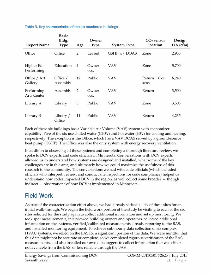
Table 3. Key characteristics of the six monitored buildings
Report Name
Basic Bldg. Type Age
Owner type System Type
CO2 sensor location
Design OA (cfm)
Office Office 2 Leased GSHP w/ DOAS Zone 2,933
Higher Ed Performing
Education 4 Owner occ.
VAV Zone 5,700
Office / Art Gallery
Office / Assembly
12 Public VAV Return + Occ. sens.
6,240
Performing Arts Center
Assembly 2 Owner occ.
VAV Return 3,500
Library A Library 5 Public VAV Zone 3,503
Library B Library / Office
11 Public VAV Return 4,235
Each of these six buildings has a Variable Air Volume (VAV) system with economizer capability. Five of the six use chilled water (CHW) and hot water (HW) for cooling and heating, respectively. The exception is the Office, which has a VAV DOAS served by a ground-source heat pump (GSHP). The Office was also the only system with energy recovery ventilation.
In addition to observing all these systems and completing a thorough literature review, we spoke to DCV experts and code officials in Minnesota. Conversations with DCV experts allowed us to understand how systems are designed and installed, what some of the key challenges are in this area, and ultimately how we could maximize the usefulness of this research to the community. The conversations we had with code officials (which included officials who interpret, review, and conduct site inspections for code compliance) helped us understand how codes impacted DCV in the region, as well collect some broader — though indirect — observations of how DCV is implemented in Minnesota.
Field Work As part of the characterization effort above, we had already visited all six of these sites for an initial walk-through. We began the field work portion of the study be visiting to each of the six sites selected for the study again to collect additional information and set up monitoring. We took spot measurements, interviewed building owners and operators, collected additional information on the systems, verified/calibrated measurements already reporting to the BAS, and installed monitoring equipment. To achieve sub-hourly data collection of six complex HVAC systems, we relied on the BAS for a significant portion of the data. We were mindful that this data might not be accurate or complete, so we completed rigorous verification of the BAS measurements, and also installed our own data loggers to collect information that was either not available from the BAS, or less reliable through the BAS.
Energy Savings from Commissioning DCV COMM-20130501-72625 | July 2015 Seventhwave 12 | P a g e
We monitored points at each of the DCV systems at both the system and the zone levels. Points monitored at the system level included:
• Outdoor air temperature, relative humidity and CO2 concentration • Flow rates: outdoor air, supply air, return air • Damper position: outside air, return air • Temperatures: mixed air, return air, supply air (both upstream and downstream of the
fan) • Coil output: valve position • Fan power: supply fan, return or exhaust fan
Points monitored at the zone level included: • Discharge air temperature • VAV damper position and/or air flow rate • Heating valve position • Zone temperature, relative humidity, and CO2 concentration • Occupancy sensor status, if available
The complete checklist for installation of site monitoring can be found in Appendix A: Monitoring Installation Checklist.
Data was monitored at five-minute intervals where available; some points were only available at 15-minute intervals. We had a direct connection to the BAS data at four of our six sites, cellular connection to much of the data at a fifth site, and relied on the owner to send us monthly trend reports (that we had created during our site visit) from their BAS. Despite this level of connectivity, some of the zone-level data, namely CO2 concentration and humidity, was collected with individual data loggers and required regular site visits to download.
Recommissioning After the first period of monitoring each system, we recommissioned them. We applied best practices gleaned from our literature review. We compiled practices relevant to both DCV recommissioning (adjusting an existing system to operate as originally designed) and commissioning (the process verifying that the DCV system functions as designed once construction is complete and the space is occupied). We wanted our work and results to be relevant to both processes; in any case there is substantial overlap between the two. This information allowed us to direct the recommissioning process. Our check list covered many areas of DCV design and construction:
• Building handover and operations • Sequence and setpoints • CO2 sensor(s) design • Airflow measurement • Measurement and verification
Energy Savings from Commissioning DCV COMM-20130501-72625 | July 2015 Seventhwave 13 | P a g e
Recommissioning Process For our monitored buildings, we first conducted virtual system performance checks of each system using the monitored data, coupled with our understanding of the DCV design intent for each building. We were able to check several areas this way before visiting the site for a formal commissioning process:
Virtual System Performance Checks (checked using BAS and logger data prior to site visit) □ Outside air (OA) damper schedule □ Unoccupied CO2 sensor readings □ OA flows vs. design vs. code □ Economizer operation □ Modulation of OA flow vs. design sequence □ Airflow measurement design vs. best practices
We added in any items already noticed or reported from owners, including measurement issues identified during our data QC.
From our virtual performance checks we created a general recommissioning checklist, and a checklist of specific items for each site; these were combined to form a master recommissioning checklist for our systems. With this checklist in hand, we visited each of the six sites and completed the recommissioning process. In addition to the ‘Virtual’ checks listed above, the recommissioning checklist included the following:
Interview with staff □ Recent adjustment to system □ Interview regarding perception of design intent □ Clarification of installation/sequence
Measurement validation □ Air temperature: SAT, MAT, RAT, OAT □ Valve position: CHW, HW □ Damper position: OA, RA □ Fan speed: supply, return (assuming manual read of VFD is correct)
Other spot checks □ Operation of supply air temperature □ Setpoints: CO2, SAT □ Pressure relationships at doorways
CO2 sensor checks □ Sensor validation/calibration □ CO2 sensor location (is it representative of zones it’s being used to control?) □ CO2 setpoint vs. ASHRAE 62.1 guidance, with consideration for actual ambient CO2
levels □ Status and relevance of automatic calibration feature
Energy Savings from Commissioning DCV COMM-20130501-72625 | July 2015 Seventhwave 14 | P a g e
Airflow measurement checks □ Airflow measurement accuracy, based on balancer measurements taken in earlier site
visit □ Whether DCV sequence is based on airflow measurement, or damper position
System performance tests □ OA damper scheduling (focusing on morning startup) □ Air handling unit (AHU) response to low and high CO2 readings □ VAV box response to low and high CO2 readings □ OA damper operation □ Occupancy sensor response (for Office/Art Gallery system only)
Sequence optimization □ Setpoint optimization (CO2 setpoint, OA flow lower limit, OA flow upper limit,
freezestat) □ Consider if design OA flow can be changed based on changes in 1) code or 2) space use
type since installation:
We’ve added descriptions and lessons learned to transform this master checklist into a guidance document for general use by any practitioner who is commissioning or recommissioning DCV systems (see Appendix C: Recommissioning Checklist).
Once these items were checked on site, we identified adjustments to system operation and requested permission from the owner to make the changes (in most cases, these steps all occurred in the same one-day site visit). Of the 20 items that we identified across 6 buildings, owners accepted and allowed modifications on 14 of them. These specific items are listed and discussed in the Savings from Commissioning section (and are summarized in Table 8). We conducted these tests and made these adjustments in visits of between 2 and 4.5 hours to each site. To supplement our own staff, we had both a controls contractor and owner’s representative on site to help us run the tests, approve any adjustments, and make those adjustments.
Occupant Survey In addition to monitoring the DCV systems, we surveyed occupants of the spaces we studied to get a sense of their overall comfort and satisfaction with the temperature, humidity and air quality of their workplace. Occupants could complete a paper survey or go online to complete an electronic survey (the two options had identical questions and answers). The paper survey was left at occupant’s work station at the time our technicians installed the monitoring equipment. Ultimately we relied on our site contacts to encourage people to complete the survey.
ASHRAE Standard 55-2013 provides clear guidelines for determining occupant thermal comfort from surveys; we based our survey on this standard. We asked occupants to rank their satisfaction with temperature, humidity and air freshness using a scale from three to negative three, where zero is neutral. The extreme ends of the scale for temperature were “very hot” to “very cold,” and “very dry” to “very humid” for humidity. The research supporting Standard 55 shows that these subjective descriptors accurately capture perceptions of comfort, allowing normalization of our results. Capturing satisfaction with air quality was somewhat more
Energy Savings from Commissioning DCV COMM-20130501-72625 | July 2015 Seventhwave 15 | P a g e
difficult. There is little previous research to draw from. Our survey experts recommended using the same type of question framework as temperature and humidity, just with different extremes. In this case we chose “very drafty” to “very stuffy” as the two extremes for measuring satisfaction with air freshness. The question was structured in the same manner and using the same scale as the questions for temperature and humidity. The occupant comfort survey can be found in Appendix B: Occupant Satisfaction Survey.
Since we did not have a standard benchmark for responses to the question regarding air freshness, we drew conclusions based on the relative distance of occupant’s responses to the neutral response. We normalized this metric based on the worst response we received, such that a neutral response equaled 0, the worst response we received equaled 1, and every other response was proportional on a scale from 0 to 1. We called this the Normalized Difference from Neutral; it is represented by Dnorm in the equation below:
Dnorm = 𝑎𝑎𝑎𝑎𝑎𝑎(𝑅𝑅𝑅𝑅𝑎𝑎𝑅𝑅𝑅𝑅𝑅𝑅𝑎𝑎𝑅𝑅)max (𝑎𝑎𝑎𝑎𝑎𝑎(𝐴𝐴𝐴𝐴𝐴𝐴 𝑅𝑅𝑅𝑅𝑎𝑎𝑅𝑅𝑅𝑅𝑅𝑅𝑎𝑎𝑅𝑅𝑎𝑎))
Analysis We used two different analysis methods to quantify energy savings from DCV, as well as additional savings from recommissioning DCV, in the six systems that we monitored. We used a spreadsheet to analytically derive energy savings from the measured data. We also used this tool to weather normalize the results to represent typical Minnesota weather.
Additionally, we used EnergyPlus to develop an energy model for each building and system. These models were calibrated to our monitored field data and used to determine whole building impacts and impacts based on prospective changes in the system. The building energy models were also valuable as a cross check with our spreadsheet analysis of the measured results.
Data Accuracy As we’ve noted, we relied on data from the BAS for much of our analysis but were mindful that this data could be inaccurate or incomplete. Spot verification proved that much of the data was fairly accurate, with minor adjustments needed for temperature.
The exception, as expected, was airflow rate, which was accurate in some cases but quite inaccurate in others. Initially, we verified accuracy of this measurement by employing a certified balancing professional to perform thorough duct traverses as a check against airflow measurement stations (AFMS). Where a simple scaling of flow rate based on the balancer’s measurement sufficed, we simply scaled the measurements from the BAS for the remainder of the study. Additionally, we checked the AFMS data using both 1) an energy balance on the AHU and 2) a flow balance between outside air (OA), supply air (SA), and return air (RA) flow measurements. This gave us four different values for air flow, with our primary focus being on OA flow as it is the biggest driver in our estimates of energy savings. Those four values were:
• The original OA AFMS (tied to the BAS) • Spot measurement by balancer (contractor)
Energy Savings from Commissioning DCV COMM-20130501-72625 | July 2015 Seventhwave 16 | P a g e
• Energy balance, i.e. percent airflow based on temperature at return and outside (only considered when ∆T between RA and OA was significant)
• Flow balance: OA + RA = SA
In addition to the scaling based on the balancer’s measurements, OA (and to some extent, SA) flow measurements were checked by plotting all four of these values concurrently. The OA flow measurements were generally acceptable, but did require adjustment at low flow in some of the cases. The four values also were used to eliminate outlier measurements. Where an OA measurement from an AFMS was below zero, greater than SA, or generally differed greatly from the other methods of calculation, a value from the flow balance or energy balance was substituted.
Finally, in addition to the checks above, the data was visually checked by plotting the following: • Temperature sensors were checked relative to each other by plotting ∆T vs valve
position and airflow • All temperatures, airflows, and damper positions were plotted in a time series and these
series were reviewed in weekly snapshots to determine general data quality (outliers were corrected)
• Heating and cooling loads implied by temperature difference were checked at every time step against fan operation, BAS schedules/sequences, and valve positions (avoiding temperature differential alone from leading us to assume load, and energy consumption, by the system)
• Fan power was plotted against fan speed and verified both visually and via correlation to the rest of the data and appropriate fan laws (outliers were corrected)
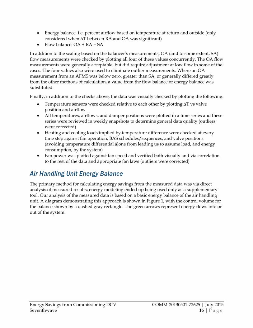
Air Handling Unit Energy Balance The primary method for calculating energy savings from the measured data was via direct analysis of measured results; energy modeling ended up being used only as a supplementary tool. Our analysis of the measured data is based on a basic energy balance of the air handling unit. A diagram demonstrating this approach is shown in Figure 1, with the control volume for the balance shown by a dashed gray rectangle. The green arrows represent energy flows into or out of the system.
Energy Savings from Commissioning DCV COMM-20130501-72625 | July 2015 Seventhwave 17 | P a g e
Figure 1. Calculation framework for analyzing energy flows in the air handling units monitored.
The resulting energy balance on this control volume is:
�̇�𝑞𝑎𝑎𝑎𝑎𝑎𝑎,𝑅𝑅𝑜𝑜𝑜𝑜𝑎𝑎𝑎𝑎𝑜𝑜𝑅𝑅 + �̇�𝑞𝑎𝑎𝑎𝑎𝑎𝑎,𝑎𝑎𝑅𝑅𝑜𝑜𝑜𝑜𝑎𝑎𝑅𝑅 + �̇�𝑊𝑓𝑓𝑎𝑎𝑅𝑅 + �̇�𝑞𝑐𝑐𝑅𝑅𝑎𝑎𝐴𝐴𝑎𝑎 = �̇�𝑞𝑎𝑎𝑎𝑎𝑎𝑎,𝑎𝑎𝑜𝑜𝑅𝑅𝑅𝑅𝐴𝐴𝑠𝑠
We assume that the full power consumption of the fan, �̇�𝑊𝑓𝑓𝑎𝑎𝑅𝑅, ends up as heat in the AHU because at all six sites the fan, belt, and motor were fully enclosed in the unit. The heat transfer from or to the coils, �̇�𝑞𝑐𝑐𝑅𝑅𝑎𝑎𝐴𝐴𝑎𝑎, can be represented by a single variable because we measured both coil valve positions, and therefore knew at each point in time whether the cooling coil or heating coil was operating (across all six systems, there were no sequences requiring simultaneous operation of heating and cooling coils).
For each �̇�𝑞𝑎𝑎𝑎𝑎𝑎𝑎 variable, we assume:
�̇�𝑞𝑎𝑎𝑎𝑎𝑎𝑎,𝑎𝑎 = �̇�𝑚𝑎𝑎ℎ𝑎𝑎
Where �̇�𝑚𝑎𝑎 is the mass flow rate of a specific airstream, and ℎ𝑎𝑎 is the specific enthalpy of a specific airstream. In addition to supply, return, and outside airstreams,3 we also measure and calculate all the necessary values for mixed air for both intermediate calculations and accuracy checks. The values of �̇�𝑚𝑎𝑎 and ℎ𝑎𝑎 are calculated from the psychrometric properties at each point, based on measured temperature and flow rate of air at each airstream (note that we recognized the need for thorough quality checks of both temperature and airflow data, as described in Data Accuracy above).
3 Note that for the Office system, the outside air condition is actually downstream of an Energy Recovery Ventilator, which preheats the air in winter and precools it in summer. This is treated as an adjustment to the outside air condition; in other words the impact of the ERV does not get counted as energy savings when calculating DCV energy savings.
Energy Savings from Commissioning DCV COMM-20130501-72625 | July 2015 Seventhwave 18 | P a g e
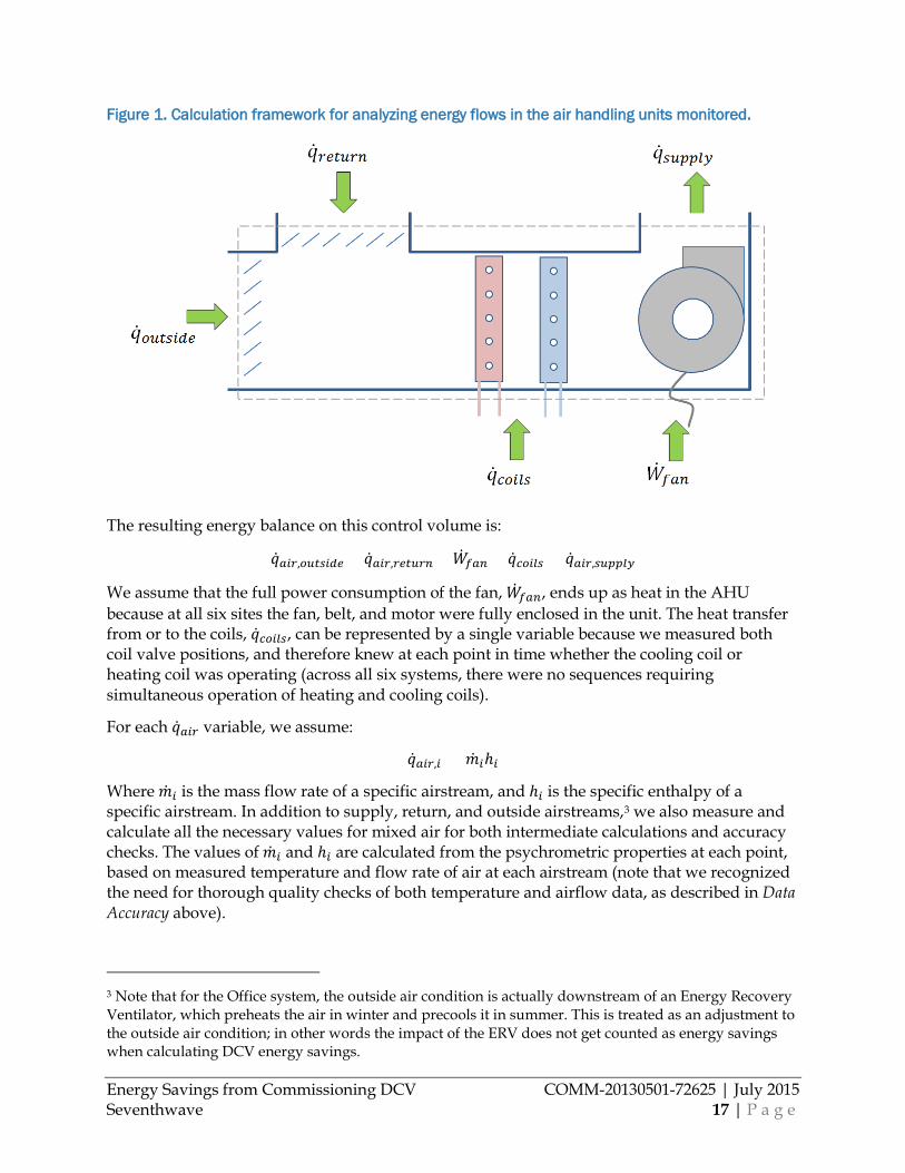
The energy savings due to DCV are then calculated at each time that measured data is available and outside air is available. Savings is calculated, again at each time, by:
∆�̇�𝑞𝑐𝑐𝑅𝑅𝑎𝑎𝐴𝐴𝑎𝑎 = �̇�𝑞𝑐𝑐𝑅𝑅𝑎𝑎𝐴𝐴𝑎𝑎(𝑂𝑂𝑂𝑂 𝑟𝑟𝑟𝑟𝑟𝑟𝑟𝑟 = 𝑑𝑑𝑟𝑟𝑑𝑑𝑑𝑑𝑑𝑑𝑑𝑑)− �̇�𝑞𝑐𝑐𝑅𝑅𝑎𝑎𝐴𝐴𝑎𝑎(𝑚𝑚𝑟𝑟𝑟𝑟𝑑𝑑𝑚𝑚𝑟𝑟𝑟𝑟𝑑𝑑)
∆�̇�𝑞𝑐𝑐𝑅𝑅𝑎𝑎𝐴𝐴𝑎𝑎 represents the load saved by DCV. If the OA flow is greater than design value due to an economizer, ∆�̇�𝑞𝑐𝑐𝑅𝑅𝑎𝑎𝐴𝐴𝑎𝑎 is set to zero. Therefore, energy savings due to DCV is directly proportional to two differences: 1) the difference in flow rate between actual and design OA, and 2) the difference in enthalpy between OA and return air. This is shown visually in Figure 2, which is a sample of one day from our measured data (at Library A).
Figure 2. Energy savings from DCV is proportional to the two differences shown here, in a sample of data from one day at Library A.
This load savings is then converted to energy savings:
∆�̇�𝑊𝑅𝑅𝐴𝐴𝑅𝑅𝑐𝑐𝑜𝑜𝑎𝑎𝑎𝑎𝑐𝑐 =∆�̇�𝑞𝑐𝑐𝑅𝑅𝑎𝑎𝐴𝐴𝑎𝑎
𝐶𝐶𝑂𝑂𝐶𝐶𝑎𝑎𝑠𝑠𝑎𝑎𝑜𝑜𝑅𝑅𝑠𝑠,𝐶𝐶+ ∆�̇�𝑊𝑓𝑓𝑎𝑎𝑅𝑅𝑎𝑎
∆�̇�𝑊𝑔𝑔𝑎𝑎𝑎𝑎 =∆�̇�𝑞𝑐𝑐𝑅𝑅𝑎𝑎𝐴𝐴𝑎𝑎
𝐶𝐶𝑂𝑂𝐶𝐶𝑎𝑎𝑠𝑠𝑎𝑎𝑜𝑜𝑅𝑅𝑠𝑠,𝐻𝐻
∆�̇�𝑊𝑓𝑓𝑎𝑎𝑅𝑅𝑎𝑎 is any fan savings (in both supply and return fans) resulting from the supply air flow rate being less than the design OA flow (if DCV were disabled in this instance, the fans would increase speed just to meet the required OA flow). The savings between these two points is calculated based on a measured fan curve (we measure both fan speed and power, which gives us a full curve over the length of the monitoring period).COPsystem is an approximate COP for the
-60
-40
-20
0
20
40
60
80
0
1000
2000
3000
4000
5000
6000
4:00 6:00 8:00 10:00 12:00 14:00 16:00 18:00 20:00
Tem
pera
ture
(o F)
OA
Flow
Rat
e (c
fm)
Savings proportionalto this area
Savings proportionalto this ∆T
Energy Savings from Commissioning DCV COMM-20130501-72625 | July 2015 Seventhwave 19 | P a g e
entire system; COPsystem,C equals the chiller plant efficiency in its predominant operating range and COPsystem,H equals the boiler efficiency in its predominant operating range.
The resulting energy is converted to energy cost using typical energy costs for Minnesota. Our savings were based on data from the Energy Information Administration for average rates across the state, which at the time of our analysis were $0.71/therm and $0.097/kWh.
Analysis of Occupancy Sensor Control One of the systems, the Office / Art Gallery system, used occupancy sensor control of VAV boxes as a part of their control sequence. This necessitated additional analysis beyond just the savings at the air handling unit level.
The occupancy control analysis begins with monitored output from each occupancy sensor attached to the system. In this particular system, when the whole system is in occupied mode but the thermostat is not calling for heating or cooling, the VAV box would normally reach a steady state of minimum airflow, �̇�𝑄𝑠𝑠𝑎𝑎𝑅𝑅, with reheat input, �̇�𝑞𝑎𝑎𝑅𝑅ℎ𝑅𝑅𝑎𝑎𝑜𝑜, to offset the cooler supply air entering the box if there is not a matching cooling load in the space. But in this scenario if the occupancy sensor status for the zone is unoccupied, the VAV box will fully shut to zero flow. This saves both 1) fan energy and, in some cases, 2) reheat energy.
For this one system we added these two quantities of energy savings to the savings calculated at the AHU level. The energy savings is estimated based on �̇�𝑄𝑠𝑠𝑎𝑎𝑅𝑅, according to:
�̇�𝑞𝑎𝑎𝑅𝑅ℎ𝑅𝑅𝑎𝑎𝑜𝑜 𝑎𝑎𝑎𝑎𝑠𝑠𝑅𝑅𝑜𝑜 = 𝐹𝐹𝑜𝑜𝑎𝑎𝑅𝑅 × �̇�𝑄𝑠𝑠𝑎𝑎𝑅𝑅 × 𝜌𝜌𝑎𝑎𝑎𝑎𝑎𝑎 × (ℎ𝑧𝑧𝑅𝑅𝑅𝑅𝑅𝑅 𝑎𝑎𝑎𝑎𝑎𝑎 − ℎ𝑆𝑆𝐴𝐴)
Where 𝜌𝜌𝑎𝑎𝑎𝑎𝑎𝑎 is the density and h is the enthalpy of the air. Fuse is a usage factor for reheat which was calibrated based on energy modeling results to represent the percentage of time that reheat would actually be used if airflow remained at �̇�𝑄𝑠𝑠𝑎𝑎𝑅𝑅 rather than going to zero. Small loads in the space as well as the dynamic nature of VAV box operation means that reheat is not needed much of the time even when box flow is at �̇�𝑄𝑠𝑠𝑎𝑎𝑅𝑅. There is no easy method to measure this factor so we calibrate it based on our energy model results. The equation, �̇�𝑞𝑎𝑎𝑅𝑅ℎ𝑅𝑅𝑎𝑎𝑜𝑜 𝑎𝑎𝑎𝑎𝑠𝑠𝑎𝑎𝑅𝑅𝑜𝑜, is only calculated for zones with reheat, when the AHU is in occupied mode, and morning warm-up is disabled. The reheat load savings (�̇�𝑞𝑎𝑎𝑅𝑅ℎ𝑅𝑅𝑎𝑎𝑜𝑜 𝑎𝑎𝑎𝑎𝑠𝑠𝑎𝑎𝑅𝑅𝑜𝑜) is then added to the load savings for the AHU and converted to energy and cost along with the energy described in the previous section.
Fan energy savings is somewhat simpler. We noted that the fan in this particular system never reached its absolute minimum speed, so we can assume that whenever a VAV box is at zero flow, the fan is providing �̇�𝑄𝑠𝑠𝑎𝑎𝑅𝑅 less flow than it otherwise would be at that time. So fan energy savings, in kWh, is simply �̇�𝑄𝑠𝑠𝑎𝑎𝑅𝑅 multiplied by the slope of the measured fan curve (in kW/cfm) at its operating point.
Weather Normalization The analysis so far has used the measured data we collected in 2014 and, for some cases, early 2015. In order for this data to be generally applicable, we weather normalized the savings results to typical weather for Minnesota. For example, in 2014 Minnesota had much colder weather than is typical; this would skew our results without normalization.
Energy Savings from Commissioning DCV COMM-20130501-72625 | July 2015 Seventhwave 20 | P a g e
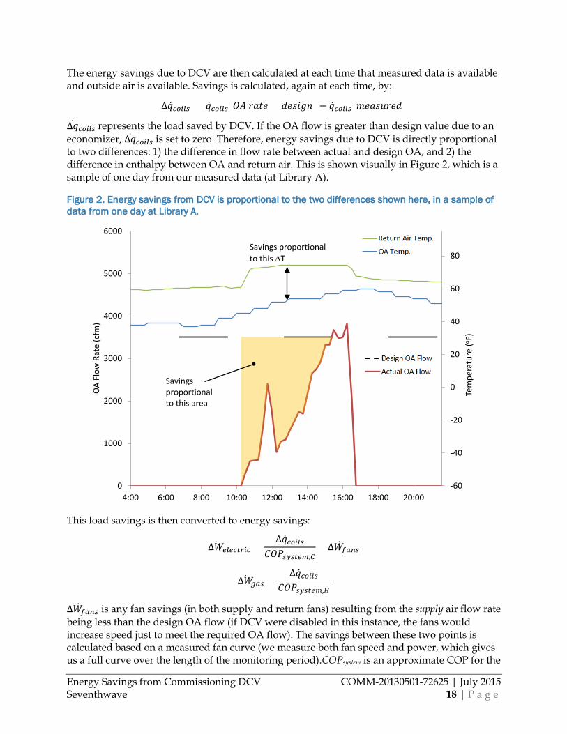
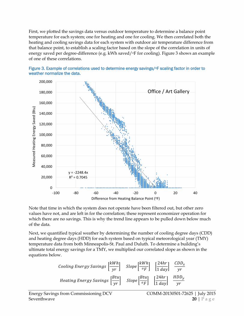
First, we plotted the savings data versus outdoor temperature to determine a balance point temperature for each system; one for heating and one for cooling. We then correlated both the heating and cooling savings data for each system with outdoor air temperature difference from that balance point, to establish a scaling factor based on the slope of the correlation in units of energy saved per degree-difference (e.g. kWh saved/oF for cooling). Figure 3 shows an example of one of these correlations.
Figure 3. Example of correlations used to determine energy savings/oF scaling factor in order to weather normalize the data.
Note that time in which the system does not operate have been filtered out, but other zero values have not, and are left in for the correlation; these represent economizer operation for which there are no savings. This is why the trend line appears to be pulled down below much of the data.
Next, we quantified typical weather by determining the number of cooling degree days (CDD) and heating degree days (HDD) for each system based on typical meteorological year (TMY) temperature data from both Minneapolis-St. Paul and Duluth. To determine a building’s ultimate total energy savings for a TMY, we multiplied our correlated slope as shown in the equations below.
𝐶𝐶𝐶𝐶𝐶𝐶𝐶𝐶𝑑𝑑𝑑𝑑𝑑𝑑 𝐸𝐸𝑑𝑑𝑟𝑟𝑟𝑟𝑑𝑑𝐸𝐸 𝑆𝑆𝑟𝑟𝑆𝑆𝑑𝑑𝑑𝑑𝑑𝑑𝑑𝑑 �𝑘𝑘𝑊𝑊ℎ𝐸𝐸𝑟𝑟 � = 𝑆𝑆𝐶𝐶𝐶𝐶𝑆𝑆𝑟𝑟 �
𝑘𝑘𝑊𝑊ℎ 𝑅𝑅𝐹𝐹 �× �
24ℎ𝑟𝑟1 𝑑𝑑𝑟𝑟𝐸𝐸�
×𝐶𝐶𝐷𝐷𝐷𝐷𝑥𝑥𝐸𝐸𝑟𝑟
𝐻𝐻𝑟𝑟𝑟𝑟𝑟𝑟𝑑𝑑𝑑𝑑𝑑𝑑 𝐸𝐸𝑑𝑑𝑟𝑟𝑟𝑟𝑑𝑑𝐸𝐸 𝑆𝑆𝑟𝑟𝑆𝑆𝑑𝑑𝑑𝑑𝑑𝑑𝑑𝑑 �𝐵𝐵𝑟𝑟𝑚𝑚𝐸𝐸𝑟𝑟 �
= 𝑆𝑆𝐶𝐶𝐶𝐶𝑆𝑆𝑟𝑟 �𝐵𝐵𝑟𝑟𝑚𝑚 𝑅𝑅𝐹𝐹 �
× �24ℎ𝑟𝑟1 𝑑𝑑𝑟𝑟𝐸𝐸�
×𝐻𝐻𝐷𝐷𝐷𝐷𝑠𝑠𝐸𝐸𝑟𝑟
y = -2248.4xR² = 0.7045
0
20,000
40,000
60,000
80,000
100,000
120,000
140,000
160,000
180,000
200,000
-100 -80 -60 -40 -20 0 20 40
Mea
sure
d He
atin
g En
ergy
Sav
ed (B
tu)
Difference from Heating Balance Point (oF)
Office / Art Gallery
Energy Savings from Commissioning DCV COMM-20130501-72625 | July 2015 Seventhwave 21 | P a g e
Where x is the cooling degree days for a given location for the cooling-specific balance point of the system in question, and y is the heating degree days for the same. Fan energy savings did not correlate strongly to weather; it was scaled based solely on the number of hours in a complete year vs. the number of hours of valid data for a given fan.
Whole Building Energy Model In addition to directly analyzing results of measured data to determine savings, we also analyzed DCV impacts through calibrated energy modeling. Since we ultimately were able to use analysis of direct measurements to determine savings for the systems, modeling became a secondary tool. However, it was still useful in quantifying scenarios that we were not able to measure directly, including prospective alternate operating scenarios. Key uses of the energy model included the following:
• Calibration of savings from occupancy sensor controlled VAV boxes on Office / Art Gallery system (we had significant data on occupancy, but had imperfect correlations to reheat energy)
• As a check of energy savings calculated analytically • Impact of the future code change (discussed below) • One commissioning scenario for which we were not able to gather enough post-
commissioning data to reliably extrapolate savings (for Library B).Figure 10
These outcomes were only required for three of the systems: Office/Art Gallery, Library B, and Higher Ed Performing Arts. As a result, three separate energy models were created.
We selected EnergyPlus for our energy modeling tool to analyze DCV. Of the software tools that we have significant expertise with, EnergyPlus and Trane TRACE were the two that offered modeling of sophisticated DCV sequences4. EnergyPlus was chosen over Trane TRACE due to its better flexibility with hourly input/output data as required by research. DOE2.2 (with eQUEST) was another option considered, but only considered briefly. Our experience modeling DCV using DOE2.2 has shown that this tool models DCV accurately for some common system configurations, but simply does not provide reasonable results with many system configurations.
We used DesignBuilder to create our building geometry and loads, and basic VAV system setup. Once we had this basic setup in DesignBuilder, we switched to working directly in EnergyPlus for maximum flexibility. Once in EnergyPlus, we refined the basic HVAC system sequences including SAT reset, schedules, and economizer operation. We then implemented DCV within EnergyPlus. Though each of the three systems had a slightly different sequence, we utilized common approaches and specific objects in EnergyPlus to execute these sequences. The specific object inputs are described below, along with a list of the key inputs for each.
ZoneAirContaminantBalance. Sets up CO2 tracking in the model. • Carbon Dioxide Concentration: Yes • Outdoor Carbon Dioxide Schedule Name: Created compact schedule with ambient CO2
concentration; we used 390 ppm at all times based on measured values.
4 TRNSYS was capable but more complex than required.

Energy Savings from Commissioning DCV COMM-20130501-72625 | July 2015 Seventhwave 22 | P a g e
Controller:OutdoorAir. Specifies economizer control, as well as the upper and lower limit for OA flow.
• Minimum Outdoor Air Flow Rate: Set to the OA flow lower limit for DCV control. For our models: 0 cfm for Library B, 3,000 cfm for Office/Art Gallery, and 3,500 cfm on Higher Ed Performing Arts.
• Maximum Outdoor Air Flow Rate: autosize (will equal the design OA flow; except for Higher Ed Performing Arts where it was equal to max SA flow rate)
• Economizer Control Type: DifferentialDryBulb (Office/Art Gallery and Higher Ed Performing Arts) or DifferentialEnthalpy (Library B)
• Economizer Maximum Limit Dry-Bulb Temperature: Maximum limit for economizer operation regardless of type. Varied by building.
• Economizer Minimum Limit Dry-Bulb temperature: Minimum limit for economizer operation regardless of type. Varied by building.
• Minimum Limit Type: FixedMinimum, meaning that the minimum OA flow is fixed regardless of what the supply air flow rate is of the system.
• Minimum Outdoor Air Schedule Name: Compact schedule that equals 0 when building is closed and equals 1 during hours of operation
• Mechanical Ventilation Controller Name: The name of the associated Controller:MechanicalVentilation object (see below).
Controller:MechanicalVentilation. Works with Controller:OutdoorAir and DesignSpecification:OutdoorAir objects to specify the amount of OA at design conditions to each zone. Also determines how OA and how OA is controlled when DCV is implemented, as well as whether DCV is enabled or disabled.
• Availability Schedule Name: Used the same compact schedule as Minimum Outdoor Air Schedule Name in Controller:OutdoorAir object; equals 0 when building is closed and equals 1 during hours of operation.
• Demand Controlled Ventilation: Yes • System Outdoor Air Method: IndoorAirQualityProcedure. Models a general single
setpoint DCV sequence. Other inputs necessary to establish the sequence are in the other objects listed here.
• Zone Maximum Outdoor Air Fraction: 1
The remaining inputs for this object are zone specific. If all spaces with DCV had similar OA requirements all were defined together with a ZoneList. If the spaces with DCV had different OA requirements (e.g. one zone is an office that has 17 CFM/person and one zone is a theater that requires 10 CFM/person) then we specified each zone and OA specification separately.
• Zone 1 Name: Name of zone or zone list for all zones that have DCV based on CO2 sensor. For Higher Ed Performing Arts this was the theater zone, for Library B this was the large library area, and for Office/Art Gallery this was all zones. For Library B, the CO2 sensor was in the return but our measurements showed that return CO2 was dominated — and essentially equaled — the CO2 concentration of the one very large space served by the system, which was the library stacks.

Energy Savings from Commissioning DCV COMM-20130501-72625 | July 2015 Seventhwave 23 | P a g e
• Design Specification Outdoor Air Object Name 1: Name of DesignSpecification:OutdoorAir object that specifies the uniform flow/person in all spaces with DCV.
• Design Specification Zone Air Distribution Object Name: Name of DesignSpecification:ZoneAirDistribution object.
ZoneControl:ContaminantController. Determines what rooms are controlled with a CO2 sensor, and essentially acts as the sensor object. This object also specifies what CO2 set point (in ppm) the system needs to meet for the given zone zone.
• Controlled Zone Name: We entered the name of the controlled zones (see the discussion of zones controlled in the Controller:MechanicalVentilation object above.
• Carbon Dioxide Control Availability Schedule Name: A compact schedule that is 1 at all times. (CO2 concentration is constantly being measured.)
• Carbon Dioxide Setpoint Schedule Name: A compact schedule with the CO2 setpoint shown for all times. For Library B and Office/Art Gallery this setting was 1000 ppm, for Higher Ed Performing Arts it was 800 ppm. (Note that if you the set point is below the ambient CO2 level then DCV will never be used; if set too high then the indoor air quality will suffer.)
DesignSpecification:OutdoorAir: Specifies the amount of OA air provided per person or per zone area. If the amount of OA per person is uniform across all zones with DCV we created a single object to modulate all those zones. If OA flow differs by zone we created an object for each zone.
• Outdoor Air Method: Flow/Person (multiple options could work here for DCV-enabled systems; we chose this because it was consistent with the way OA was designed for our systems and also worked with the DCV sequences).
• Outdoor Air Flow per Person: Varied by zone. • Outdoor Air Flow per Zone Floor Area: As we chose the flow/person method, this input
is ignored. • Outdoor Air Flow per zone: As we chose the flow/person method, this input is ignored.
Output:Variables: Specifies what outputs EnergyPlus should print during simulation. We printed and viewed many outputs, but the three that were used substantially more than all others were Outdoor air flow rate (using volume flow rate at supply fan outlet), Supply air temperature (using node temperature at supply fan outlet), and Supply air flow rate (using volume flow rate at AHU OA inlet).
For the Office/Art Gallery system, we modified one additional object to estimate the impact of the occupancy sensor control implemented there (see the Analysis of Occupancy Sensor Control section above).
AirTerminal:SingleDuctVAV:Reheat: Schedules the VAV minimum air flow fraction, in this case to modulate according to occupancy.
• Zone Minimum Air Flow Input Method: For Office/Art Gallery, set to Scheduled • Constant Minimum Air Flow Fraction: For Office/Art Gallery, not used with Scheduled
method.
Energy Savings from Commissioning DCV COMM-20130501-72625 | July 2015 Seventhwave 24 | P a g e
• Minimum Air Flow Fraction Schedule Name: For Office/Art Gallery, we created a compact schedule to represent the actual occupancy sensor data we collected (assuming 0 flow when zones were unoccupied).
Once the models were built, we calibrated each to the measured data for each system. The following outputs were the primary objectives for calibration; the associated inputs used to adjust the model are also shown.
Zone heating and cooling loads: Matched by adjusting occupancy (where measured data wasn’t available) plug loads, and primary envelope properties.
Supply air temperature: Matched by adjusting the supply air reset schedule.
Supply air flow rate: Matched by first matching supply air temperature and zone loads (above) through their respective associated adjustments, and then by adjusting the minimum air flow fraction in each zone.
Outdoor air flow rate: This was matched at a first level by adjusting the economizer control in the shoulder seasons, and OA flow per person at presumed peak occupancy. This was matched further by adjusting the DCV inputs (while staying within limits implied by any evidence we had of the actual DCV sequence).
Prospective Scenarios through Parametric Modeling The calibrated models were deemed the “Current Scenario.” The models were than modified parametrically to approximate prospective scenarios; results were compared with the Current Scenario. In one prospective scenario the models were used to approximate a case without DCV, to determine savings from implementing DCV. To shut DCV off, first the Controller:MechanicalVentilation object in the Demand Control Ventilation input was set to No. Second, the minimum Outdoor Air Flow Rate input in the Controller:OutdoorAir object was changed to the design OA flow.
In another prospective scenario, the future changes in the ventilation code were approximated by changing the required design OA flow for each zone. To implement this modification, the Outdoor Air Flow per Person input in the DesignSpecification:OutdoorAir object was adjusted to the new code value. Finally, the model was used to approximate the post-recommissioning scenario. In this instance a variety of changes were made based on the changes we implemented in the actual systems during recommissioning. Library B is worth additional discussion because the energy model was the primary source of the results for energy savings from recommissioning (we were not able to get adequate post-commissioning data to extrapolate those savings analytically). For Library B, we adjusted:
• the OA damper ‘occupied’ start to 10am in the Minimum Outdoor Air Schedule, • the Maximum Outdoor Air Flow Rate input in the Controller:OutdoorAir object to 40%
of design SA rate, • the Minimum Outdoor Air Flow Rate input in the Controller:OutdoorAir object to 5% of
design SA rate, and • the Carbon Dioxide Setpoint Schedule to be set to 950 ppm.
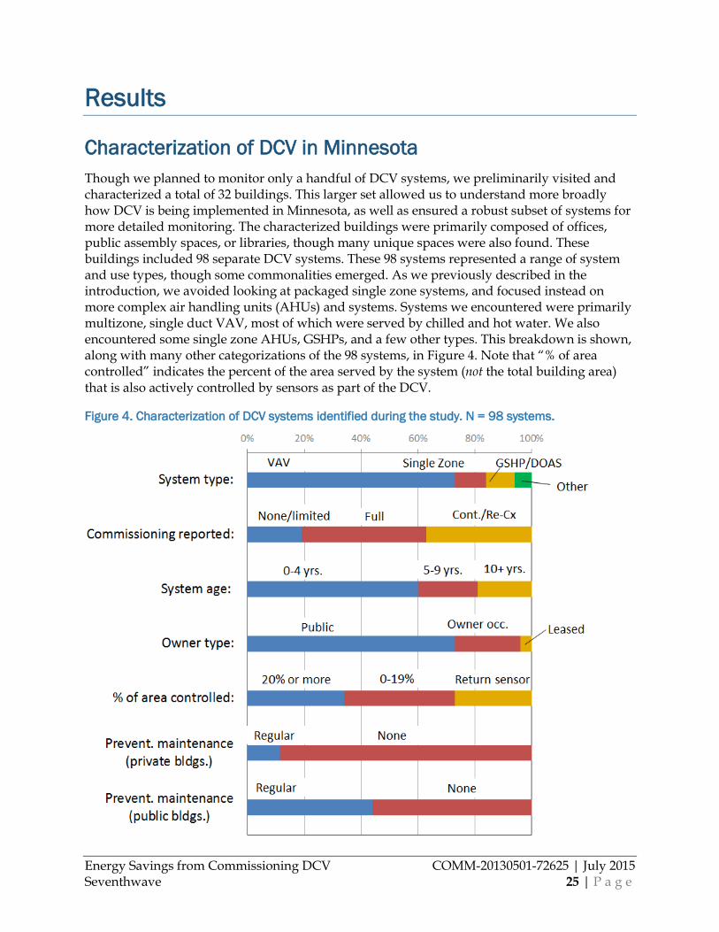
Energy Savings from Commissioning DCV COMM-20130501-72625 | July 2015 Seventhwave 25 | P a g e
Results
Characterization of DCV in Minnesota Though we planned to monitor only a handful of DCV systems, we preliminarily visited and characterized a total of 32 buildings. This larger set allowed us to understand more broadly how DCV is being implemented in Minnesota, as well as ensured a robust subset of systems for more detailed monitoring. The characterized buildings were primarily composed of offices, public assembly spaces, or libraries, though many unique spaces were also found. These buildings included 98 separate DCV systems. These 98 systems represented a range of system and use types, though some commonalities emerged. As we previously described in the introduction, we avoided looking at packaged single zone systems, and focused instead on more complex air handling units (AHUs) and systems. Systems we encountered were primarily multizone, single duct VAV, most of which were served by chilled and hot water. We also encountered some single zone AHUs, GSHPs, and a few other types. This breakdown is shown, along with many other categorizations of the 98 systems, in Figure 4. Note that “% of area controlled” indicates the percent of the area served by the system (not the total building area) that is also actively controlled by sensors as part of the DCV.
Figure 4. Characterization of DCV systems identified during the study. N = 98 systems.
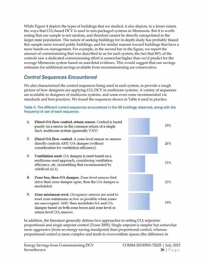
Energy Savings from Commissioning DCV COMM-20130501-72625 | July 2015 Seventhwave 26 | P a g e
While Figure 4 depicts the types of buildings that we studied, it also depicts, to a lesser extent, the ways that CO2-based DCV is used in non-packaged systems in Minnesota. But it is worth noting that our sample is not random, and therefore cannot be directly extrapolated to the larger state population. The nature of seeking buildings for in-depth study has probably biased this sample more toward public buildings, and for similar reasons toward buildings that have a more hands-on management. For example, in the second bar in the figure, we report the amount of commissioning that was described to us for each system; the fact that 80% of the controls saw a dedicated commissioning effort is somewhat higher than we’d predict for the average Minnesota system based on anecdotal evidence. This would suggest that our savings estimates for additional savings available from recommissioning are conservative.
Control Sequences Encountered We also characterized the control sequences being used in each system, to provide a rough picture of how designers are applying CO2 DCV in multizone systems. A variety of sequences are available to designers of multizone systems, and some even come recommended via standards and best practices. We found the sequences shown in Table 4 used in practice.
Table 4. The different control sequences encountered in the 98 buildings observed, along with the frequency of use of each sequence.
In addition, the literature generally defines two approaches to setting CO2 setpoints: proportional and single setpoint control (Trane 2005). Single setpoint is simpler but somewhat more aggressive (from an energy-saving standpoint) than proportional control, whereas proportional control is more complex and tends to overventilate spaces (the difference in
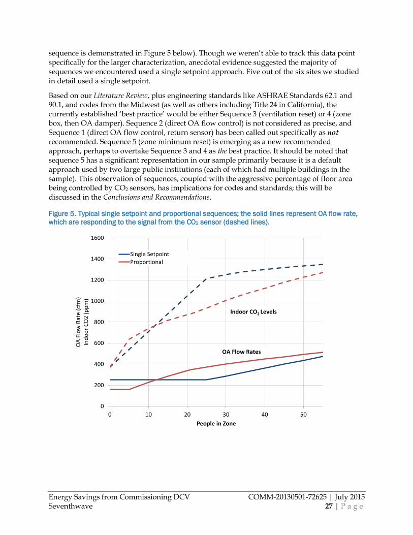
Energy Savings from Commissioning DCV COMM-20130501-72625 | July 2015 Seventhwave 27 | P a g e
sequence is demonstrated in Figure 5 below). Though we weren’t able to track this data point specifically for the larger characterization, anecdotal evidence suggested the majority of sequences we encountered used a single setpoint approach. Five out of the six sites we studied in detail used a single setpoint.
Based on our Literature Review, plus engineering standards like ASHRAE Standards 62.1 and 90.1, and codes from the Midwest (as well as others including Title 24 in California), the currently established ‘best practice’ would be either Sequence 3 (ventilation reset) or 4 (zone box, then OA damper). Sequence 2 (direct OA flow control) is not considered as precise, and Sequence 1 (direct OA flow control, return sensor) has been called out specifically as not recommended. Sequence 5 (zone minimum reset) is emerging as a new recommended approach, perhaps to overtake Sequence 3 and 4 as the best practice. It should be noted that sequence 5 has a significant representation in our sample primarily because it is a default approach used by two large public institutions (each of which had multiple buildings in the sample). This observation of sequences, coupled with the aggressive percentage of floor area being controlled by CO2 sensors, has implications for codes and standards; this will be discussed in the Conclusions and Recommendations.
Figure 5. Typical single setpoint and proportional sequences; the solid lines represent OA flow rate, which are responding to the signal from the CO2 sensor (dashed lines).
0
200
400
600
800
1000
1200
1400
1600
0 10 20 30 40 50
OA
Flow
Rat
e (c
fm)
Indo
or C
O2
(ppm
)
People in Zone
Single SetpointProportional
Indoor CO2 Levels
OA Flow Rates
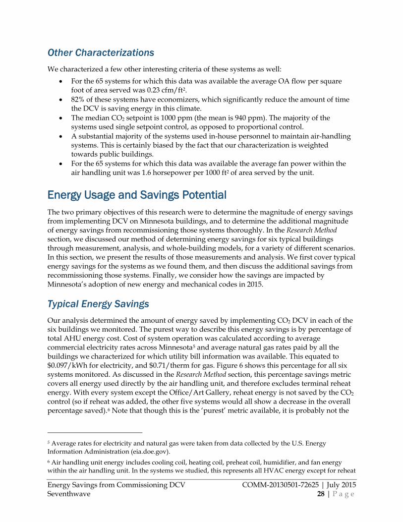
Energy Savings from Commissioning DCV COMM-20130501-72625 | July 2015 Seventhwave 28 | P a g e
Other Characterizations We characterized a few other interesting criteria of these systems as well:
• For the 65 systems for which this data was available the average OA flow per square foot of area served was 0.23 cfm/ft2.
• 82% of these systems have economizers, which significantly reduce the amount of time the DCV is saving energy in this climate.
• The median CO2 setpoint is 1000 ppm (the mean is 940 ppm). The majority of the systems used single setpoint control, as opposed to proportional control.
• A substantial majority of the systems used in-house personnel to maintain air-handling systems. This is certainly biased by the fact that our characterization is weighted towards public buildings.
• For the 65 systems for which this data was available the average fan power within the air handling unit was 1.6 horsepower per 1000 ft2 of area served by the unit.
Energy Usage and Savings Potential The two primary objectives of this research were to determine the magnitude of energy savings from implementing DCV on Minnesota buildings, and to determine the additional magnitude of energy savings from recommissioning those systems thoroughly. In the Research Method section, we discussed our method of determining energy savings for six typical buildings through measurement, analysis, and whole-building models, for a variety of different scenarios. In this section, we present the results of those measurements and analysis. We first cover typical energy savings for the systems as we found them, and then discuss the additional savings from recommissioning those systems. Finally, we consider how the savings are impacted by Minnesota’s adoption of new energy and mechanical codes in 2015.
Typical Energy Savings Our analysis determined the amount of energy saved by implementing CO2 DCV in each of the six buildings we monitored. The purest way to describe this energy savings is by percentage of total AHU energy cost. Cost of system operation was calculated according to average commercial electricity rates across Minnesota5 and average natural gas rates paid by all the buildings we characterized for which utility bill information was available. This equated to $0.097/kWh for electricity, and $0.71/therm for gas. Figure 6 shows this percentage for all six systems monitored. As discussed in the Research Method section, this percentage savings metric covers all energy used directly by the air handling unit, and therefore excludes terminal reheat energy. With every system except the Office/Art Gallery, reheat energy is not saved by the CO2 control (so if reheat was added, the other five systems would all show a decrease in the overall percentage saved).6 Note that though this is the ‘purest’ metric available, it is probably not the
5 Average rates for electricity and natural gas were taken from data collected by the U.S. Energy Information Administration (eia.doe.gov). 6 Air handling unit energy includes cooling coil, heating coil, preheat coil, humidifier, and fan energy within the air handling unit. In the systems we studied, this represents all HVAC energy except for reheat
Energy Savings from Commissioning DCV COMM-20130501-72625 | July 2015 Seventhwave 29 | P a g e
best, as AHU energy is just a fraction of overall building energy usage, or even HVAC energy usage, given that in cold climates reheat energy is a major end use. We will therefore cover other, better metrics next.
Figure 6. Percentage of total air-handling unit energy saved by CO2 DCV. Note that reheat energy was not included in the total energy for this calculation.
The energy savings at the air-handling unit ranges from 14 to 49%, with a median savings of 34%. Natural gas savings (from avoided heating load) is the dominant source of energy cost savings.7 This reflects the climate in Minnesota, in which ventilation energy is dominated by heating (many more heating degree days than cooling), a significant portion of cooling load handled by economizer modes, and most larger buildings are heated by natural gas. In fact, after seasonal and weather normalization, natural gas makes up 80% of the cost savings across
occurring at the VAV terminal units. That reheat is not able to be included in the percent-savings results. All systems that we studied except the Office utilize terminal reheat. 7 The Office building has a ground-source heat pump system, in which all of the HVAC energy (including heating) is electric. The Higher Ed Performing Arts Building shows higher proportion of electric savings in this pre-normalized condition, because it had less data collection in heating season than the other sites, but data was collected for the complete cooling season. Seasonal and weather normalized data is presented in the remainder of the section, in which this issue is negated.
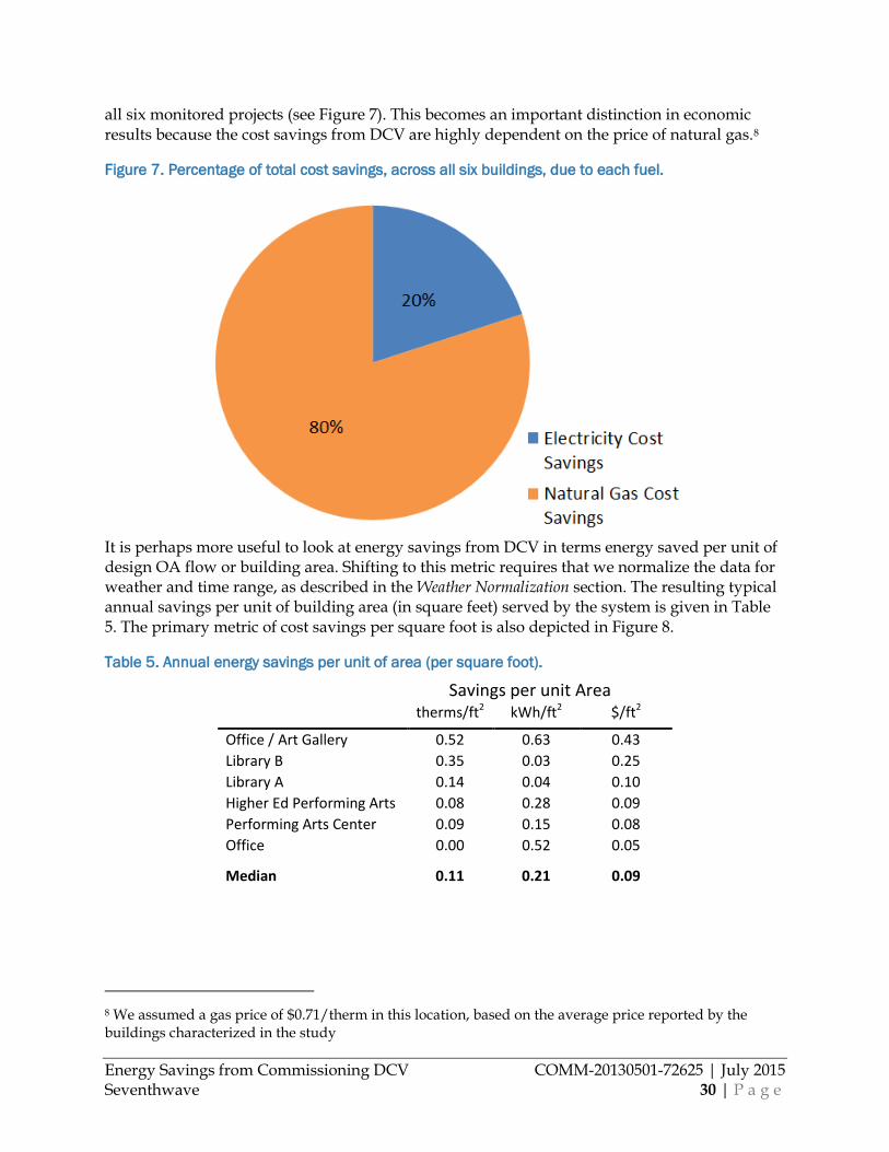
Energy Savings from Commissioning DCV COMM-20130501-72625 | July 2015 Seventhwave 30 | P a g e
all six monitored projects (see Figure 7). This becomes an important distinction in economic results because the cost savings from DCV are highly dependent on the price of natural gas.8
Figure 7. Percentage of total cost savings, across all six buildings, due to each fuel.
It is perhaps more useful to look at energy savings from DCV in terms energy saved per unit of design OA flow or building area. Shifting to this metric requires that we normalize the data for weather and time range, as described in the Weather Normalization section. The resulting typical annual savings per unit of building area (in square feet) served by the system is given in Table 5. The primary metric of cost savings per square foot is also depicted in Figure 8.
Table 5. Annual energy savings per unit of area (per square foot).
Savings per unit Area therms/ft2 kWh/ft2 $/ft2
Office / Art Gallery 0.52 0.63 0.43 Library B 0.35 0.03 0.25 Library A 0.14 0.04 0.10 Higher Ed Performing Arts 0.08 0.28 0.09 Performing Arts Center 0.09 0.15 0.08 Office 0.00 0.52 0.05
Median 0.11 0.21 0.09
8 We assumed a gas price of $0.71/therm in this location, based on the average price reported by the buildings characterized in the study
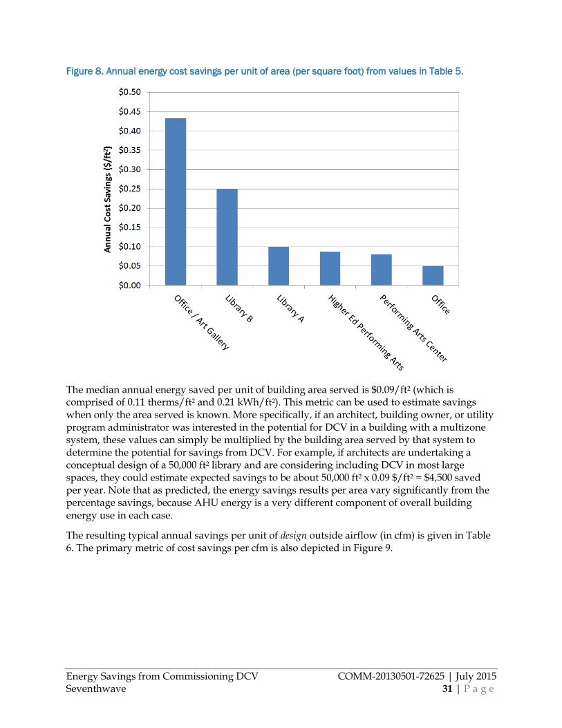
Energy Savings from Commissioning DCV COMM-20130501-72625 | July 2015 Seventhwave 31 | P a g e
Figure 8. Annual energy cost savings per unit of area (per square foot) from values in Table 5.
The median annual energy saved per unit of building area served is $0.09/ft2 (which is comprised of 0.11 therms/ft2 and 0.21 kWh/ft2). This metric can be used to estimate savings when only the area served is known. More specifically, if an architect, building owner, or utility program administrator was interested in the potential for DCV in a building with a multizone system, these values can simply be multiplied by the building area served by that system to determine the potential for savings from DCV. For example, if architects are undertaking a conceptual design of a 50,000 ft2 library and are considering including DCV in most large spaces, they could estimate expected savings to be about 50,000 ft2 x 0.09 $/ft2 = $4,500 saved per year. Note that as predicted, the energy savings results per area vary significantly from the percentage savings, because AHU energy is a very different component of overall building energy use in each case.
The resulting typical annual savings per unit of design outside airflow (in cfm) is given in Table 6. The primary metric of cost savings per cfm is also depicted in Figure 9.
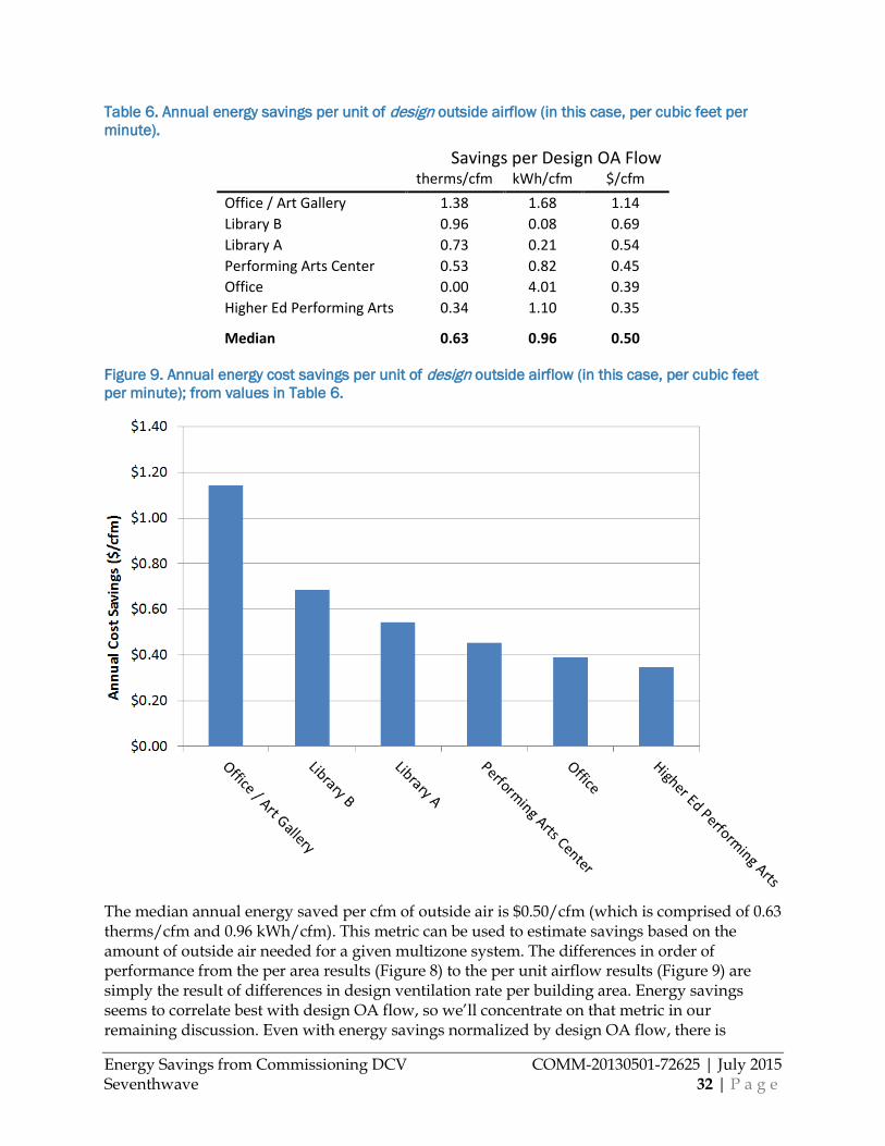
Energy Savings from Commissioning DCV COMM-20130501-72625 | July 2015 Seventhwave 32 | P a g e
Table 6. Annual energy savings per unit of design outside airflow (in this case, per cubic feet per minute).
Savings per Design OA Flow therms/cfm kWh/cfm $/cfm
Office / Art Gallery 1.38 1.68 1.14 Library B 0.96 0.08 0.69 Library A 0.73 0.21 0.54 Performing Arts Center 0.53 0.82 0.45 Office 0.00 4.01 0.39 Higher Ed Performing Arts 0.34 1.10 0.35
Median 0.63 0.96 0.50
Figure 9. Annual energy cost savings per unit of design outside airflow (in this case, per cubic feet per minute); from values in Table 6.
The median annual energy saved per cfm of outside air is $0.50/cfm (which is comprised of 0.63 therms/cfm and 0.96 kWh/cfm). This metric can be used to estimate savings based on the amount of outside air needed for a given multizone system. The differences in order of performance from the per area results (Figure 8) to the per unit airflow results (Figure 9) are simply the result of differences in design ventilation rate per building area. Energy savings seems to correlate best with design OA flow, so we’ll concentrate on that metric in our remaining discussion. Even with energy savings normalized by design OA flow, there is
Energy Savings from Commissioning DCV COMM-20130501-72625 | July 2015 Seventhwave 33 | P a g e
variation in this result from system to system. This remaining variation is due to differences in control implementation between these systems. For example, the highest and lowest performers in Figure 9 are both notably different ventilation designs than the others. The Office / Art Gallery, which shows substantially higher savings than the others (at $1.14/cfm), uses both CO2 sensors and occupancy sensors to control ventilation and airflow. Its sequence is similar to sequence 5 (zone minimum reset) described back in Table 4.
The Higher Ed Performing Arts building is the lowest performer of the six systems, also due to its control sequence. First, it uses a much more conservative OA flow lower limit (lower limit with CO2 control, not to be confused with design minimum) than the others, so outside air does not decrease as much as other spaces even when the spaces are completely empty of people. Secondly, this system uses a control based on damper position rather than measuring outside air flowrate directly. An airflow measurement station was installed to make this direct measurement but it is inaccurate, and therefore not used, because its installation does not meet manufacturer specifications.9
The Office is the next lowest performer of the remaining systems. Its savings are limited by the fact that it is the only building in the sample that implemented both DCV and energy recovery ventilation (ERV). The energy recovery ventilation has already significantly reduced the amount of energy required to condition the outside air, so there is less energy remaining to be saved by DCV. Note that even though the savings potential is lower, there are still significant savings to be obtained from DCV even with ERV on the system.
The remaining three systems perhaps exemplify ‘typical’ DCV savings, with between $0.45 and $0.69 saved annually per cfm. It is worth noting that all these systems have controls on a significant majority of their OA, so the design cfm is close to the controlled cfm. This differs from a system where only a fraction of the design OA is being controlled, for example an office where just the conference and common areas are controlled and none of the private or open office areas are. In such a system it is possible that only 25% of the OA would be controlled.
We can easily do a rough (non-weighted) extrapolation to the entire state of Minnesota. The state has 827 million ft2 of total commercial building space10 in buildings where CO2 based DCV is feasible. If DCV was enabled on every air handling unit in those buildings, and every unit delivered 0.23 cfm of outside air per square foot (the average of the systems we characterized), then 190 million cfm of outside air would be controlled across the entire state. This results in an annual total potential savings of 120 million therms and 182 million kWh11, which has a value of $103 million to the state’s commercial customers. Now, only about 19% of the state’s building
9 In this case, the station was installed in a duct that had diameter changes and turns very nearby. The outside air intake was not designed with any longer, straighter sections that are needed for airflow measurement. Anecdotally, this seemed to be a common issue with DCV systems we observed.
10 Commercial Building Energy Consumption Survey, Energy Information Administration, http://www.eia.gov/consumption/commercial/, accessed October 2012. Building types where DCV is feasible are assumed to be Education, Food Service, Retail, Office, Public Assembly, Religious Worship, and Service. 11 Noting that we had a mix of five buildings with gas heat and one with electric (heat pump) heat, which is note perfectly representative of the mix of heating fuels across all of Minnesota.
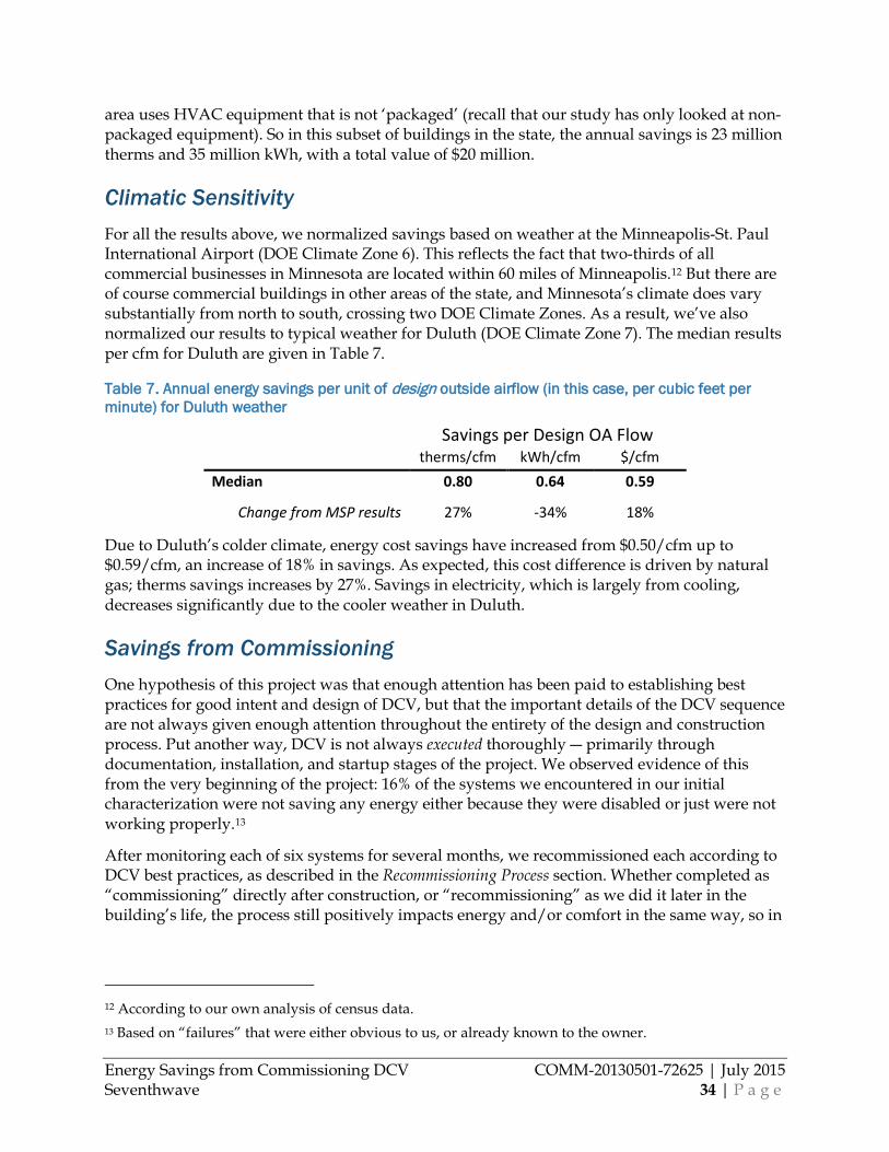
Energy Savings from Commissioning DCV COMM-20130501-72625 | July 2015 Seventhwave 34 | P a g e
area uses HVAC equipment that is not ‘packaged’ (recall that our study has only looked at non-packaged equipment). So in this subset of buildings in the state, the annual savings is 23 million therms and 35 million kWh, with a total value of $20 million.
Climatic Sensitivity For all the results above, we normalized savings based on weather at the Minneapolis-St. Paul International Airport (DOE Climate Zone 6). This reflects the fact that two-thirds of all commercial businesses in Minnesota are located within 60 miles of Minneapolis.12 But there are of course commercial buildings in other areas of the state, and Minnesota’s climate does vary substantially from north to south, crossing two DOE Climate Zones. As a result, we’ve also normalized our results to typical weather for Duluth (DOE Climate Zone 7). The median results per cfm for Duluth are given in Table 7.
Table 7. Annual energy savings per unit of design outside airflow (in this case, per cubic feet per minute) for Duluth weather
Savings per Design OA Flow therms/cfm kWh/cfm $/cfm
Median 0.80 0.64 0.59
Change from MSP results 27% -34% 18%
Due to Duluth’s colder climate, energy cost savings have increased from $0.50/cfm up to $0.59/cfm, an increase of 18% in savings. As expected, this cost difference is driven by natural gas; therms savings increases by 27%. Savings in electricity, which is largely from cooling, decreases significantly due to the cooler weather in Duluth.
Savings from Commissioning One hypothesis of this project was that enough attention has been paid to establishing best practices for good intent and design of DCV, but that the important details of the DCV sequence are not always given enough attention throughout the entirety of the design and construction process. Put another way, DCV is not always executed thoroughly ― primarily through documentation, installation, and startup stages of the project. We observed evidence of this from the very beginning of the project: 16% of the systems we encountered in our initial characterization were not saving any energy either because they were disabled or just were not working properly.13
After monitoring each of six systems for several months, we recommissioned each according to DCV best practices, as described in the Recommissioning Process section. Whether completed as “commissioning” directly after construction, or “recommissioning” as we did it later in the building’s life, the process still positively impacts energy and/or comfort in the same way, so in
12 According to our own analysis of census data. 13 Based on “failures” that were either obvious to us, or already known to the owner.
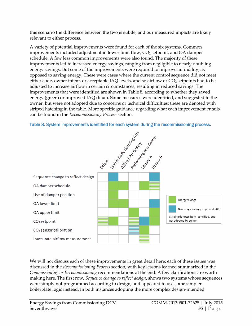
Energy Savings from Commissioning DCV COMM-20130501-72625 | July 2015 Seventhwave 35 | P a g e
this scenario the difference between the two is subtle, and our measured impacts are likely relevant to either process.
A variety of potential improvements were found for each of the six systems. Common improvements included adjustment in lower limit flow, CO2 setpoint, and OA damper schedule. A few less common improvements were also found. The majority of these improvements led to increased energy savings, ranging from negligible to nearly doubling energy savings. But some of the improvements were required to improve air quality, as opposed to saving energy. These were cases where the current control sequence did not meet either code, owner intent, or acceptable IAQ levels, and so airflow or CO2 setpoints had to be adjusted to increase airflow in certain circumstances, resulting in reduced savings. The improvements that were identified are shown in Table 8, according to whether they saved energy (green) or improved IAQ (blue). Some measures were identified, and suggested to the owner, but were not adopted due to concerns or technical difficulties; these are denoted with striped hatching in the table. More specific guidance regarding what each improvement entails can be found in the Recommissioning Process section.
Table 8. System improvements identified for each system during the recommissioning process.
We will not discuss each of these improvements in great detail here; each of these issues was discussed in the Recommissioning Process section, with key lessons learned summarized in the Commissioning or Recommissioning recommendations at the end. A few clarifications are worth making here. The first row, Sequence change to reflect design, shows two systems whose sequences were simply not programmed according to design, and appeared to use some simpler boilerplate logic instead. In both instances adopting the more complex design-intended
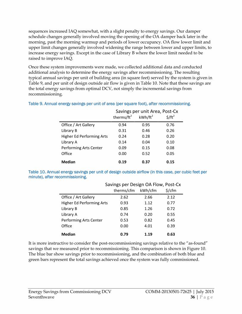
Energy Savings from Commissioning DCV COMM-20130501-72625 | July 2015 Seventhwave 36 | P a g e
sequences increased IAQ somewhat, with a slight penalty to energy savings. Our damper schedule changes generally involved moving the opening of the OA damper back later in the morning, past the morning warmup and periods of lower occupancy. OA flow lower limit and upper limit changes generally involved widening the range between lower and upper limits, to increase energy savings. Except in the case of Library B where the lower limit needed to be raised to improve IAQ.
Once these system improvements were made, we collected additional data and conducted additional analysis to determine the energy savings after recommissioning. The resulting typical annual savings per unit of building area (in square feet) served by the system is given in Table 9, and per unit of design outside air flow is given in Table 10. Note that these savings are the total energy savings from optimal DCV, not simply the incremental savings from recommissioning.
Table 9. Annual energy savings per unit of area (per square foot), after recommissioning.
Savings per unit Area, Post-Cx therms/ft2 kWh/ft2 $/ft2
Office / Art Gallery 0.94 0.95 0.76 Library B 0.31 0.46 0.26 Higher Ed Performing Arts 0.24 0.28 0.20 Library A 0.14 0.04 0.10 Performing Arts Center 0.09 0.15 0.08 Office 0.00 0.52 0.05
Median 0.19 0.37 0.15
Table 10. Annual energy savings per unit of design outside airflow (in this case, per cubic feet per minute), after recommissioning.
Savings per Design OA Flow, Post-Cx therms/cfm kWh/cfm $/cfm
Office / Art Gallery 2.62 2.66 2.12 Higher Ed Performing Arts 0.93 1.12 0.77 Library B 0.85 1.26 0.72 Library A 0.74 0.20 0.55 Performing Arts Center 0.53 0.82 0.45 Office 0.00 4.01 0.39
Median 0.79 1.19 0.63
It is more instructive to consider the post-recommissioning savings relative to the “as-found” savings that we measured prior to recommissioning. This comparison is shown in Figure 10. The blue bar show savings prior to recommissioning, and the combination of both blue and green bars represent the total savings achieved once the system was fully commissioned.
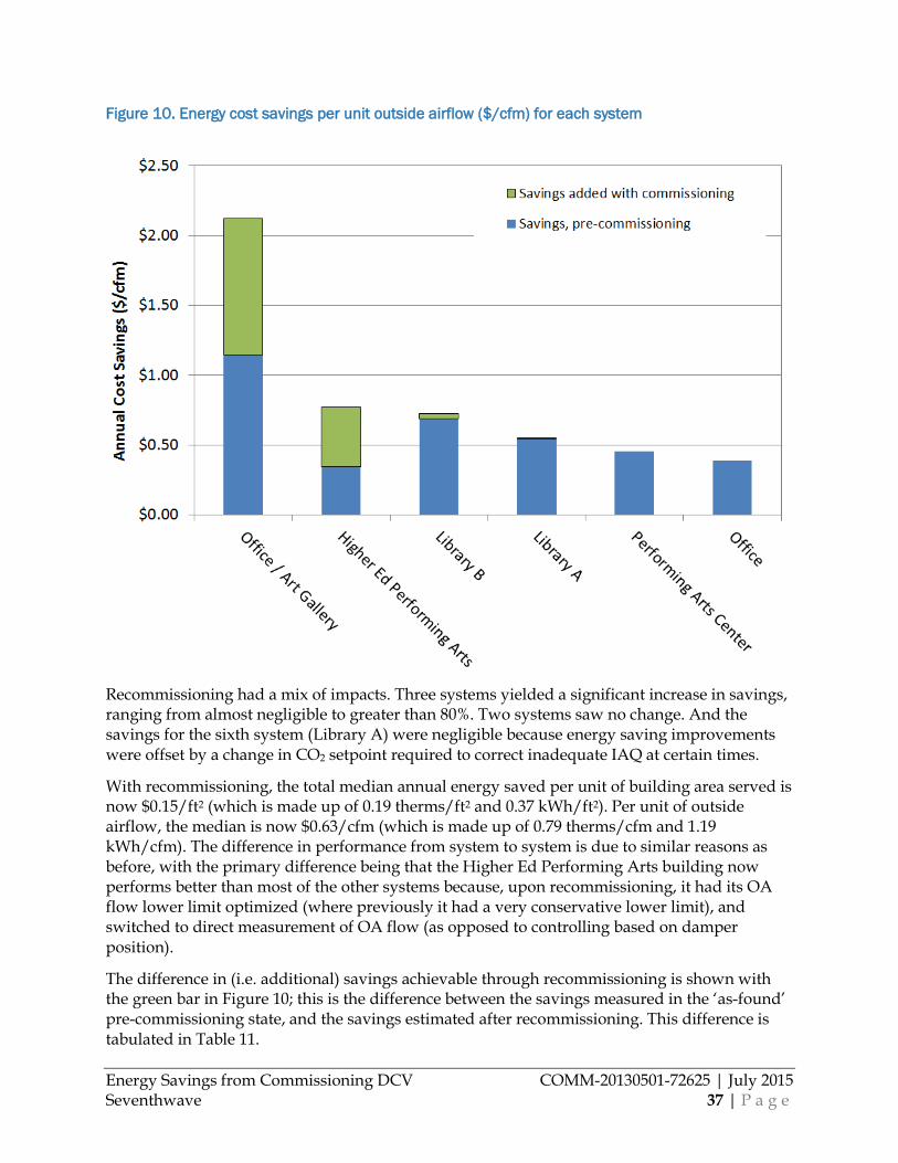
Energy Savings from Commissioning DCV COMM-20130501-72625 | July 2015 Seventhwave 37 | P a g e
Figure 10. Energy cost savings per unit outside airflow ($/cfm) for each system
Recommissioning had a mix of impacts. Three systems yielded a significant increase in savings, ranging from almost negligible to greater than 80%. Two systems saw no change. And the savings for the sixth system (Library A) were negligible because energy saving improvements were offset by a change in CO2 setpoint required to correct inadequate IAQ at certain times.
With recommissioning, the total median annual energy saved per unit of building area served is now $0.15/ft2 (which is made up of 0.19 therms/ft2 and 0.37 kWh/ft2). Per unit of outside airflow, the median is now $0.63/cfm (which is made up of 0.79 therms/cfm and 1.19 kWh/cfm). The difference in performance from system to system is due to similar reasons as before, with the primary difference being that the Higher Ed Performing Arts building now performs better than most of the other systems because, upon recommissioning, it had its OA flow lower limit optimized (where previously it had a very conservative lower limit), and switched to direct measurement of OA flow (as opposed to controlling based on damper position).
The difference in (i.e. additional) savings achievable through recommissioning is shown with the green bar in Figure 10; this is the difference between the savings measured in the ‘as-found’ pre-commissioning state, and the savings estimated after recommissioning. This difference is tabulated in Table 11.
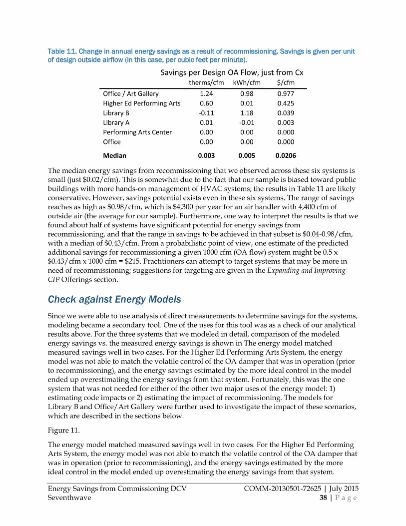
Energy Savings from Commissioning DCV COMM-20130501-72625 | July 2015 Seventhwave 38 | P a g e
Table 11. Change in annual energy savings as a result of recommissioning. Savings is given per unit of design outside airflow (in this case, per cubic feet per minute).
Savings per Design OA Flow, just from Cx therms/cfm kWh/cfm $/cfm
Office / Art Gallery 1.24 0.98 0.977 Higher Ed Performing Arts 0.60 0.01 0.425 Library B -0.11 1.18 0.039 Library A 0.01 -0.01 0.003 Performing Arts Center 0.00 0.00 0.000 Office 0.00 0.00 0.000
Median 0.003 0.005 0.0206
The median energy savings from recommissioning that we observed across these six systems is small (just $0.02/cfm). This is somewhat due to the fact that our sample is biased toward public buildings with more hands-on management of HVAC systems; the results in Table 11 are likely conservative. However, savings potential exists even in these six systems. The range of savings reaches as high as $0.98/cfm, which is $4,300 per year for an air handler with 4,400 cfm of outside air (the average for our sample). Furthermore, one way to interpret the results is that we found about half of systems have significant potential for energy savings from recommissioning, and that the range in savings to be achieved in that subset is $0.04-0.98/cfm, with a median of $0.43/cfm. From a probabilistic point of view, one estimate of the predicted additional savings for recommissioning a given 1000 cfm (OA flow) system might be 0.5 x $0.43/cfm x 1000 cfm = $215. Practitioners can attempt to target systems that may be more in need of recommissioning; suggestions for targeting are given in the Expanding and Improving CIP Offerings section.
Check against Energy Models Since we were able to use analysis of direct measurements to determine savings for the systems, modeling became a secondary tool. One of the uses for this tool was as a check of our analytical results above. For the three systems that we modeled in detail, comparison of the modeled energy savings vs. the measured energy savings is shown in The energy model matched measured savings well in two cases. For the Higher Ed Performing Arts System, the energy model was not able to match the volatile control of the OA damper that was in operation (prior to recommissioning), and the energy savings estimated by the more ideal control in the model ended up overestimating the energy savings from that system. Fortunately, this was the one system that was not needed for either of the other two major uses of the energy model: 1) estimating code impacts or 2) estimating the impact of recommissioning. The models for Library B and Office/Art Gallery were further used to investigate the impact of these scenarios, which are described in the sections below.
Figure 11.
The energy model matched measured savings well in two cases. For the Higher Ed Performing Arts System, the energy model was not able to match the volatile control of the OA damper that was in operation (prior to recommissioning), and the energy savings estimated by the more ideal control in the model ended up overestimating the energy savings from that system.
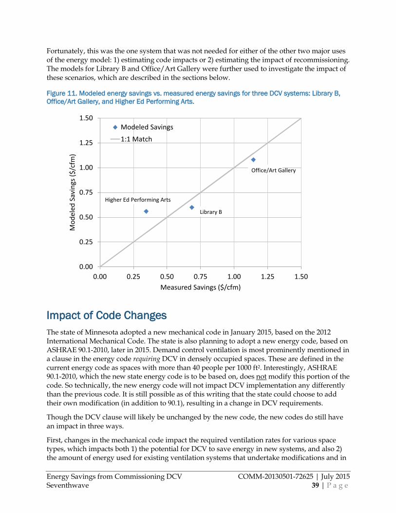
Energy Savings from Commissioning DCV COMM-20130501-72625 | July 2015 Seventhwave 39 | P a g e
Fortunately, this was the one system that was not needed for either of the other two major uses of the energy model: 1) estimating code impacts or 2) estimating the impact of recommissioning. The models for Library B and Office/Art Gallery were further used to investigate the impact of these scenarios, which are described in the sections below.
Figure 11. Modeled energy savings vs. measured energy savings for three DCV systems: Library B, Office/Art Gallery, and Higher Ed Performing Arts.
Impact of Code Changes The state of Minnesota adopted a new mechanical code in January 2015, based on the 2012 International Mechanical Code. The state is also planning to adopt a new energy code, based on ASHRAE 90.1-2010, later in 2015. Demand control ventilation is most prominently mentioned in a clause in the energy code requiring DCV in densely occupied spaces. These are defined in the current energy code as spaces with more than 40 people per 1000 ft2. Interestingly, ASHRAE 90.1-2010, which the new state energy code is to be based on, does not modify this portion of the code. So technically, the new energy code will not impact DCV implementation any differently than the previous code. It is still possible as of this writing that the state could choose to add their own modification (in addition to 90.1), resulting in a change in DCV requirements.
Though the DCV clause will likely be unchanged by the new code, the new codes do still have an impact in three ways.
First, changes in the mechanical code impact the required ventilation rates for various space types, which impacts both 1) the potential for DCV to save energy in new systems, and also 2) the amount of energy used for existing ventilation systems that undertake modifications and in
0.00
0.25
0.50
0.75
1.00
1.25
1.50
0.00 0.25 0.50 0.75 1.00 1.25 1.50
Mod
eled
Sav
ings
($/c
fm)
Measured Savings ($/cfm)
Modeled Savings
1:1 Match
Library B
Office/Art Gallery
Higher Ed Performing Arts
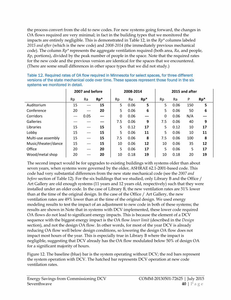
Energy Savings from Commissioning DCV COMM-20130501-72625 | July 2015 Seventhwave 40 | P a g e
the process convert from the old to new codes. For new systems going forward, the changes in OA flows required are very minimal; in fact in the building types that we monitored the impacts are entirely negligible. This is demonstrated in Table 12, in the Rp* columns labeled 2015 and after (which is the new code) and 2008-2014 (the immediately previous mechanical code). The column Rp* represents the aggregate ventilation required (both area, Ra, and people, Rp, portions), divided by the peak number of people in the space. Note that the required rates for the new code and the previous version are identical for the spaces that we encountered. (There are some small differences in other space types that we did not study.)
Table 12. Required rates of OA flow required in Minnesota for select spaces, for three different versions of the state mechanical code over time. These spaces represent those found in the six systems we monitored in detail.
2007 and before 2008-2014 2015 and after
Rp Ra Rp* Rp Ra Rp* Rp Ra P Rp* Auditorium 15 --- 15 5 0.06 5 5 0.06 150 5 Conference 20 --- 20 5 0.06 6 5 0.06 50 6 Corridors --- 0.05 --- 0 0.06 --- 0 0.06 N/A --- Galleries --- --- --- 7.5 0.06 9 7.5 0.06 40 9 Libraries 15 --- 15 5 0.12 17 5 0.12 10 17 Lobby 15 --- 15 5 0.06 11 5 0.06 10 11 Multi-use assembly 15 --- 15 7.5 0.06 8 7.5 0.06 100 8 Music/theater/dance 15 --- 15 10 0.06 12 10 0.06 35 12 Office 20 --- 20 5 0.06 17 5 0.06 5 17 Wood/metal shop 20 --- 20 10 0.18 19 10 0.18 20 19
The second impact would be for upgrades to existing buildings with systems older than about seven years, when systems were governed by the older, ASHRAE 62.1-2001-based code. This code had very substantial differences from the new state mechanical code (see the 2007 and before section of Table 12). For the six buildings that we studied, only Library B and the Office / Art Gallery are old enough systems (11 years and 12 years old, respectively) such that they were installed under an older code. In the case of Library B, the new ventilation rates are 51% lower than at the time of the original design. In the case of the Office / Art Gallery, the new ventilation rates are 49% lower than at the time of the original design. We used energy modeling results to test the impact of an adjustment to new code in both of these systems; the results are shown in Note that in systems with DCV implemented, these lower code required OA flows do not lead to significant energy impacts. This is because the element of a DCV sequence with the biggest energy impact is the OA flow lower limit (described in the Design section), and not the design OA flow. In other words, for most of the year DCV is already reducing OA flow well below design conditions, so lowering the design OA flow does not impact most hours of the year. This is especially true in Library B where the impact is negligible, suggesting that DCV already has the OA flow modulated below 50% of design OA for a significant majority of hours.
Figure 12. The baseline (blue) bar is the system operating without DCV; the red bars represent the system operation with DCV. The hatched bar represents DCV operation at new code ventilation rates.
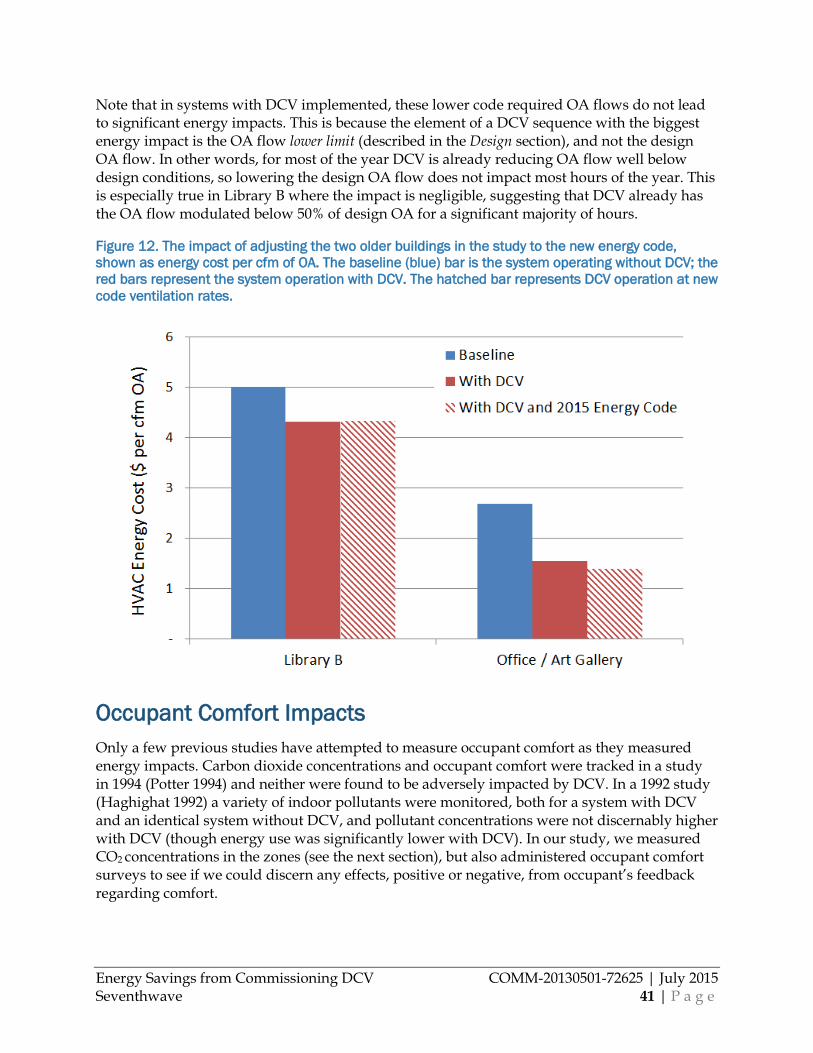
Energy Savings from Commissioning DCV COMM-20130501-72625 | July 2015 Seventhwave 41 | P a g e
Note that in systems with DCV implemented, these lower code required OA flows do not lead to significant energy impacts. This is because the element of a DCV sequence with the biggest energy impact is the OA flow lower limit (described in the Design section), and not the design OA flow. In other words, for most of the year DCV is already reducing OA flow well below design conditions, so lowering the design OA flow does not impact most hours of the year. This is especially true in Library B where the impact is negligible, suggesting that DCV already has the OA flow modulated below 50% of design OA for a significant majority of hours.
Figure 12. The impact of adjusting the two older buildings in the study to the new energy code, shown as energy cost per cfm of OA. The baseline (blue) bar is the system operating without DCV; the red bars represent the system operation with DCV. The hatched bar represents DCV operation at new code ventilation rates.
Occupant Comfort Impacts Only a few previous studies have attempted to measure occupant comfort as they measured energy impacts. Carbon dioxide concentrations and occupant comfort were tracked in a study in 1994 (Potter 1994) and neither were found to be adversely impacted by DCV. In a 1992 study (Haghighat 1992) a variety of indoor pollutants were monitored, both for a system with DCV and an identical system without DCV, and pollutant concentrations were not discernably higher with DCV (though energy use was significantly lower with DCV). In our study, we measured CO2 concentrations in the zones (see the next section), but also administered occupant comfort surveys to see if we could discern any effects, positive or negative, from occupant’s feedback regarding comfort.
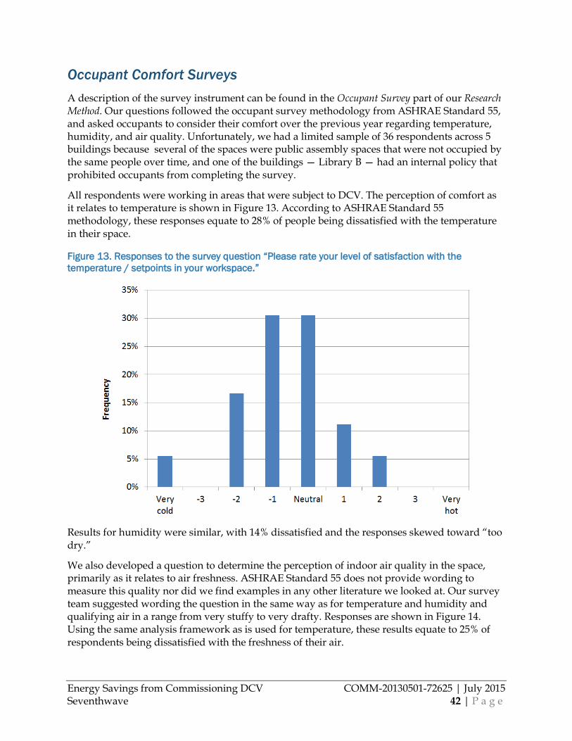
Energy Savings from Commissioning DCV COMM-20130501-72625 | July 2015 Seventhwave 42 | P a g e
Occupant Comfort Surveys A description of the survey instrument can be found in the Occupant Survey part of our Research Method. Our questions followed the occupant survey methodology from ASHRAE Standard 55, and asked occupants to consider their comfort over the previous year regarding temperature, humidity, and air quality. Unfortunately, we had a limited sample of 36 respondents across 5 buildings because several of the spaces were public assembly spaces that were not occupied by the same people over time, and one of the buildings — Library B — had an internal policy that prohibited occupants from completing the survey.
All respondents were working in areas that were subject to DCV. The perception of comfort as it relates to temperature is shown in Figure 13. According to ASHRAE Standard 55 methodology, these responses equate to 28% of people being dissatisfied with the temperature in their space.
Figure 13. Responses to the survey question “Please rate your level of satisfaction with the temperature / setpoints in your workspace.”
Results for humidity were similar, with 14% dissatisfied and the responses skewed toward “too dry.”
We also developed a question to determine the perception of indoor air quality in the space, primarily as it relates to air freshness. ASHRAE Standard 55 does not provide wording to measure this quality nor did we find examples in any other literature we looked at. Our survey team suggested wording the question in the same way as for temperature and humidity and qualifying air in a range from very stuffy to very drafty. Responses are shown in Figure 14. Using the same analysis framework as is used for temperature, these results equate to 25% of respondents being dissatisfied with the freshness of their air.
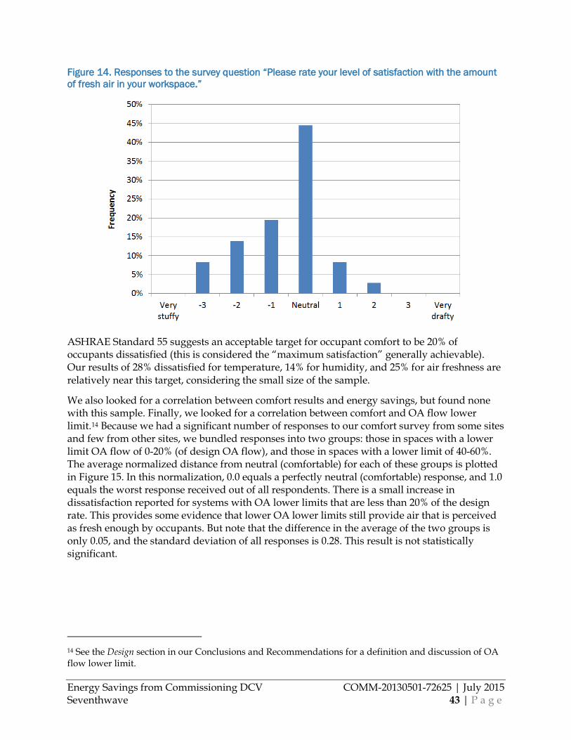
Energy Savings from Commissioning DCV COMM-20130501-72625 | July 2015 Seventhwave 43 | P a g e
Figure 14. Responses to the survey question “Please rate your level of satisfaction with the amount of fresh air in your workspace.”
ASHRAE Standard 55 suggests an acceptable target for occupant comfort to be 20% of occupants dissatisfied (this is considered the “maximum satisfaction” generally achievable). Our results of 28% dissatisfied for temperature, 14% for humidity, and 25% for air freshness are relatively near this target, considering the small size of the sample.
We also looked for a correlation between comfort results and energy savings, but found none with this sample. Finally, we looked for a correlation between comfort and OA flow lower limit.14 Because we had a significant number of responses to our comfort survey from some sites and few from other sites, we bundled responses into two groups: those in spaces with a lower limit OA flow of 0-20% (of design OA flow), and those in spaces with a lower limit of 40-60%. The average normalized distance from neutral (comfortable) for each of these groups is plotted in Figure 15. In this normalization, 0.0 equals a perfectly neutral (comfortable) response, and 1.0 equals the worst response received out of all respondents. There is a small increase in dissatisfaction reported for systems with OA lower limits that are less than 20% of the design rate. This provides some evidence that lower OA lower limits still provide air that is perceived as fresh enough by occupants. But note that the difference in the average of the two groups is only 0.05, and the standard deviation of all responses is 0.28. This result is not statistically significant.
14 See the Design section in our Conclusions and Recommendations for a definition and discussion of OA flow lower limit.
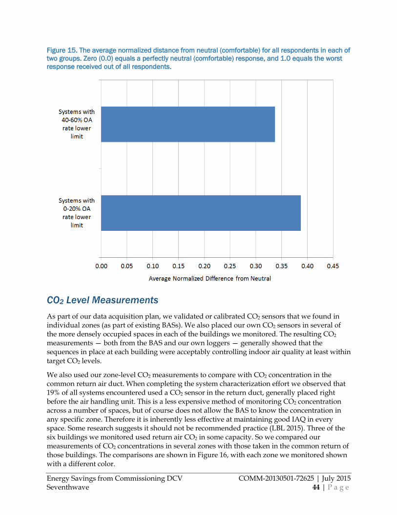
Energy Savings from Commissioning DCV COMM-20130501-72625 | July 2015 Seventhwave 44 | P a g e
Figure 15. The average normalized distance from neutral (comfortable) for all respondents in each of two groups. Zero (0.0) equals a perfectly neutral (comfortable) response, and 1.0 equals the worst response received out of all respondents.
CO2 Level Measurements As part of our data acquisition plan, we validated or calibrated CO2 sensors that we found in individual zones (as part of existing BASs). We also placed our own CO2 sensors in several of the more densely occupied spaces in each of the buildings we monitored. The resulting CO2 measurements — both from the BAS and our own loggers — generally showed that the sequences in place at each building were acceptably controlling indoor air quality at least within target CO2 levels.
We also used our zone-level CO2 measurements to compare with CO2 concentration in the common return air duct. When completing the system characterization effort we observed that 19% of all systems encountered used a CO2 sensor in the return duct, generally placed right before the air handling unit. This is a less expensive method of monitoring CO2 concentration across a number of spaces, but of course does not allow the BAS to know the concentration in any specific zone. Therefore it is inherently less effective at maintaining good IAQ in every space. Some research suggests it should not be recommended practice (LBL 2015). Three of the six buildings we monitored used return air CO2 in some capacity. So we compared our measurements of CO2 concentrations in several zones with those taken in the common return of those buildings. The comparisons are shown in Figure 16, with each zone we monitored shown with a different color.
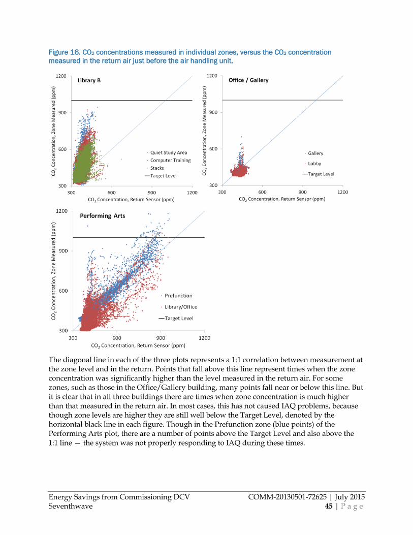
Energy Savings from Commissioning DCV COMM-20130501-72625 | July 2015 Seventhwave 45 | P a g e
Figure 16. CO2 concentrations measured in individual zones, versus the CO2 concentration measured in the return air just before the air handling unit.
The diagonal line in each of the three plots represents a 1:1 correlation between measurement at the zone level and in the return. Points that fall above this line represent times when the zone concentration was significantly higher than the level measured in the return air. For some zones, such as those in the Office/Gallery building, many points fall near or below this line. But it is clear that in all three buildings there are times when zone concentration is much higher than that measured in the return air. In most cases, this has not caused IAQ problems, because though zone levels are higher they are still well below the Target Level, denoted by the horizontal black line in each figure. Though in the Prefunction zone (blue points) of the Performing Arts plot, there are a number of points above the Target Level and also above the 1:1 line — the system was not properly responding to IAQ during these times.
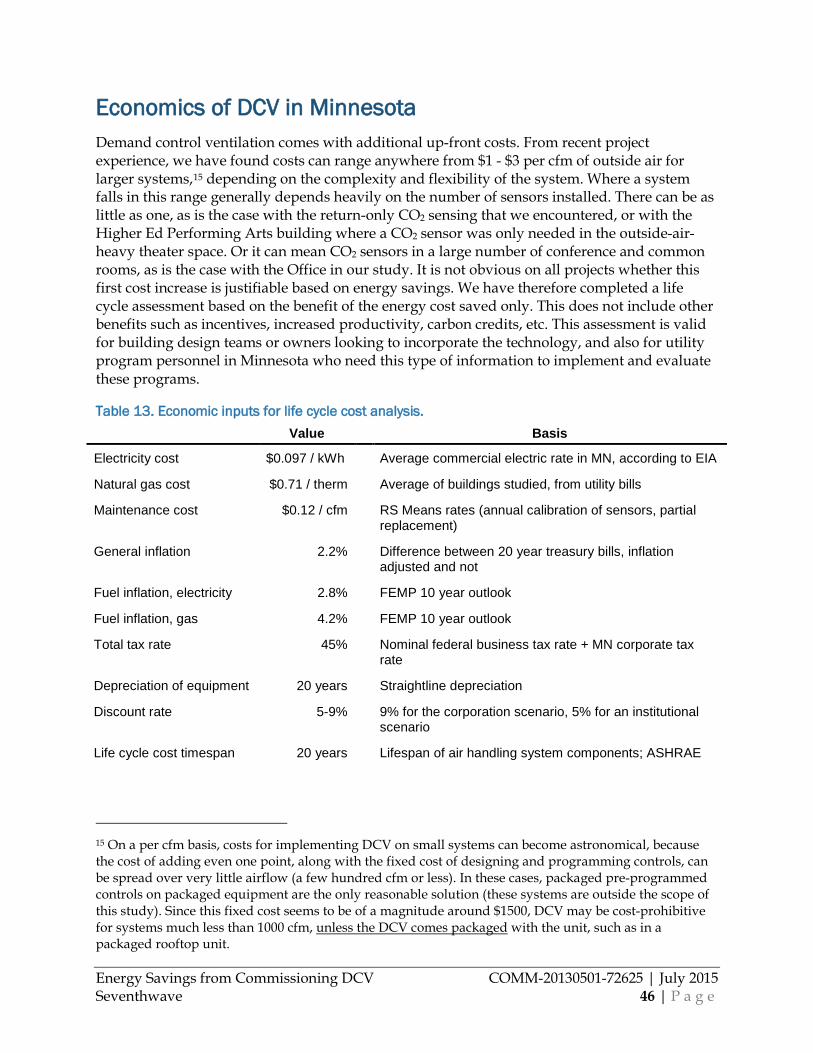
Energy Savings from Commissioning DCV COMM-20130501-72625 | July 2015 Seventhwave 46 | P a g e
Economics of DCV in Minnesota Demand control ventilation comes with additional up-front costs. From recent project experience, we have found costs can range anywhere from $1 - $3 per cfm of outside air for larger systems,15 depending on the complexity and flexibility of the system. Where a system falls in this range generally depends heavily on the number of sensors installed. There can be as little as one, as is the case with the return-only CO2 sensing that we encountered, or with the Higher Ed Performing Arts building where a CO2 sensor was only needed in the outside-air-heavy theater space. Or it can mean CO2 sensors in a large number of conference and common rooms, as is the case with the Office in our study. It is not obvious on all projects whether this first cost increase is justifiable based on energy savings. We have therefore completed a life cycle assessment based on the benefit of the energy cost saved only. This does not include other benefits such as incentives, increased productivity, carbon credits, etc. This assessment is valid for building design teams or owners looking to incorporate the technology, and also for utility program personnel in Minnesota who need this type of information to implement and evaluate these programs.
Table 13. Economic inputs for life cycle cost analysis. Value Basis
Electricity cost $0.097 / kWh Average commercial electric rate in MN, according to EIA
Natural gas cost $0.71 / therm Average of buildings studied, from utility bills
Maintenance cost $0.12 / cfm RS Means rates (annual calibration of sensors, partial replacement)
General inflation 2.2% Difference between 20 year treasury bills, inflation adjusted and not
Fuel inflation, electricity 2.8% FEMP 10 year outlook
Fuel inflation, gas 4.2% FEMP 10 year outlook
Total tax rate 45% Nominal federal business tax rate + MN corporate tax rate
Depreciation of equipment 20 years Straightline depreciation
Discount rate 5-9% 9% for the corporation scenario, 5% for an institutional scenario
Life cycle cost timespan 20 years Lifespan of air handling system components; ASHRAE
15 On a per cfm basis, costs for implementing DCV on small systems can become astronomical, because the cost of adding even one point, along with the fixed cost of designing and programming controls, can be spread over very little airflow (a few hundred cfm or less). In these cases, packaged pre-programmed controls on packaged equipment are the only reasonable solution (these systems are outside the scope of this study). Since this fixed cost seems to be of a magnitude around $1500, DCV may be cost-prohibitive for systems much less than 1000 cfm, unless the DCV comes packaged with the unit, such as in a packaged rooftop unit.
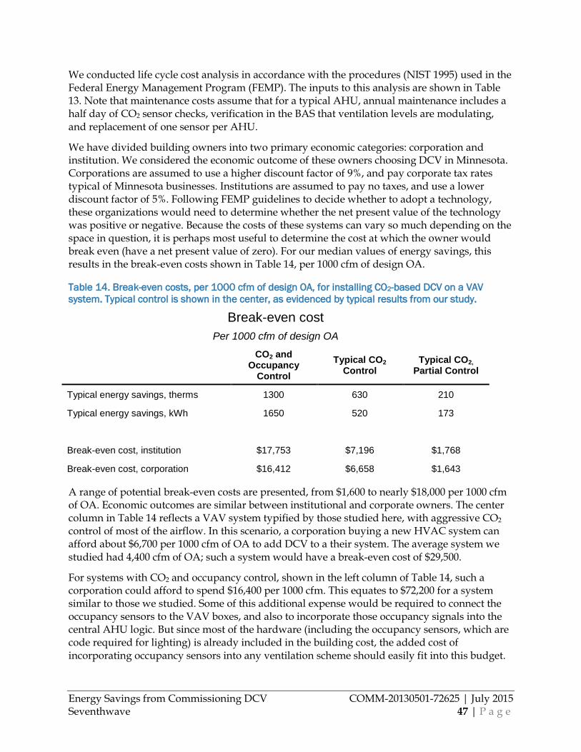
Energy Savings from Commissioning DCV COMM-20130501-72625 | July 2015 Seventhwave 47 | P a g e
We conducted life cycle cost analysis in accordance with the procedures (NIST 1995) used in the Federal Energy Management Program (FEMP). The inputs to this analysis are shown in Table 13. Note that maintenance costs assume that for a typical AHU, annual maintenance includes a half day of CO2 sensor checks, verification in the BAS that ventilation levels are modulating, and replacement of one sensor per AHU.
We have divided building owners into two primary economic categories: corporation and institution. We considered the economic outcome of these owners choosing DCV in Minnesota. Corporations are assumed to use a higher discount factor of 9%, and pay corporate tax rates typical of Minnesota businesses. Institutions are assumed to pay no taxes, and use a lower discount factor of 5%. Following FEMP guidelines to decide whether to adopt a technology, these organizations would need to determine whether the net present value of the technology was positive or negative. Because the costs of these systems can vary so much depending on the space in question, it is perhaps most useful to determine the cost at which the owner would break even (have a net present value of zero). For our median values of energy savings, this results in the break-even costs shown in Table 14, per 1000 cfm of design OA.
Table 14. Break-even costs, per 1000 cfm of design OA, for installing CO2-based DCV on a VAV system. Typical control is shown in the center, as evidenced by typical results from our study.
Break-even cost Per 1000 cfm of design OA
CO2 and Occupancy
Control Typical CO2
Control Typical CO2,
Partial Control
Typical energy savings, therms 1300 630 210
Typical energy savings, kWh 1650 520 173
Break-even cost, institution $17,753 $7,196 $1,768
Break-even cost, corporation $16,412 $6,658 $1,643
A range of potential break-even costs are presented, from $1,600 to nearly $18,000 per 1000 cfm of OA. Economic outcomes are similar between institutional and corporate owners. The center column in Table 14 reflects a VAV system typified by those studied here, with aggressive CO2 control of most of the airflow. In this scenario, a corporation buying a new HVAC system can afford about $6,700 per 1000 cfm of OA to add DCV to a their system. The average system we studied had 4,400 cfm of OA; such a system would have a break-even cost of $29,500.
For systems with CO2 and occupancy control, shown in the left column of Table 14, such a corporation could afford to spend $16,400 per 1000 cfm. This equates to $72,200 for a system similar to those we studied. Some of this additional expense would be required to connect the occupancy sensors to the VAV boxes, and also to incorporate those occupancy signals into the central AHU logic. But since most of the hardware (including the occupancy sensors, which are code required for lighting) is already included in the building cost, the added cost of incorporating occupancy sensors into any ventilation scheme should easily fit into this budget.
Energy Savings from Commissioning DCV COMM-20130501-72625 | July 2015 Seventhwave 48 | P a g e
Some systems only use CO2 control in a fraction of the zones, often conference, training, and other similar gathering spaces. This approach is exemplified in the Partial Control column at the right of Table 14. We assume in this example that such a scheme impacts 33% of the OA. Such an approach has a breakeven cost of about $1,700 for every 1000 cfm.
Though we would recommend that these more technical and thorough economic metrics be used to judge the merit of DCV, some readers will still be interested in payback metrics. For typical systems, if we assume an installed cost of $2 per cfm the payback is about 4-5 years for the ‘Typical System’ represented in Table 14. The ‘Partial Control’ system represented in the same table (where only heavily occupied rooms get CO2 control) would certainly cost less. If its cost were $1 per cfm, this approach would have a payback of 7-8 years.
We can also use our results to consider the economics of the recommissioning process itself. As evidenced in Figure 10, there is quite a lot of variability in the impact of recommissioning these systems. On one end, there is a significant IAQ improvement but no financial gain at all from recommissioning. On the other end, savings of $0.04-0.98 per cfm were realized in systems with significant room for improvement, with the median of these being $0.43/cfm. So if a system has some significant operational issues that yield $0.43/cfm savings upon recommissioning, and the probability of a system having such potential is about 1/2 (the ratio we encountered) then the expected savings from recommissioning a given project would be $0.21/cfm. With our life-cycle cost analysis, this results in a breakeven cost of recommissioning of $2,900 per 1000 cfm, which equates to $12,800 for a system similar to the sizes we encountered. With such a high cost of breaking even, the results of our sample indicate that recommissioning DCV systems is highly economic.
Our costs for recommissioning these systems included our engineering time for identifying potential improvements — generally a half day — and our cost for bringing in the relevant controls technician — between a half and full day. Costs for both engineer’s and technician’s time are generally between $110-145 per hour. These inputs yield a range of paybacks for recommissioning DCV of between <1 year and 2.5 years, for a single system. For buildings that have multiple similar systems, the economies of scale can decrease the payback substantially from there.
Energy Savings from Commissioning DCV COMM-20130501-72625 | July 2015 Seventhwave 49 | P a g e
Conclusions and Recommendations
DCV Systems in Minnesota We encountered a large variety of approaches to DCV in Minnesota buildings. There were however commonalities to many of the systems. First of all, single-duct, multizone VAV is by far the most common non-packaged HVAC system type for large buildings with DCV. In an initial characterization of 98 systems, 73% of the systems were of this type. Over 80% of these also had economizers, including the six systems we monitored and analyzed. The prevalence of economizers is worth noting because the results above attest that DCV is still an effective savings measure in Minnesota’s climate even with economizer mode leading to much fewer run-hours for the DCV sequence.
It was also apparent that DCV is still a fairly new approach in the state; 60% of systems were less than five years old, and 82% of systems were less than 10 years old. This is likely driven by recent code requirements for DCV, and increased emphasis on energy savings in general.
The biggest difference in the systems that we characterized was in their specific DCV approach. This is to some extent a result of there being no single ‘best’ sequence for DCV. But there are a few best practices established, and the approaches that we observed vary considerably beyond these recommendations. The sequences that we identified were summarized in Table 4. In general, designers and operators of DCV systems lean toward more aggressive DCV controls, taking advantage of large energy savings potential in Minnesota’s extreme climate. We found a tendency toward direct control of OA dampers, without consideration for system ventilation efficiency,16 in 67% of systems. And in 19% of the systems we observed, the CO2 sensor was placed in a common return duct. These approaches are aggressive in terms of energy savings, but may not be optimal for IAQ in all situations, at least as described by ASHRAE Standard 62.1, as discussed above.
The “Zone Minimum Reset” sequence that we describe in Table 4 is emerging as a best practice in the industry (and could find its way into future versions of ASHRAE Standard 62.1), and was found in 19% of the systems we encountered. So a portion of designers and operators in the state are implementing systems at the leading edge of the industry. This sequence is also aggressive, but uses a large number of occupancy sensors to do so without compromising IAQ.
Viability of CO2 DCV Perhaps the most important conclusion from this study is that DCV in large VAV systems saves significant energy and cost for building owners, operators, and tenants. The median savings of the systems we studied in depth was 34% of air handling unit energy consumption, which
16 System ventilation efficiency does not relate to energy efficiency, but rather IAQ; it is the efficiency with which the system distributes fresh air to occupants. ASHRAE Standard 62.1 introduces the concept of system ventilation efficiency for multizone systems, and describes a best practice for DCV that would recalculate this efficiency as system operation changed in real time. We found that only 15% of systems follow this specific practice.
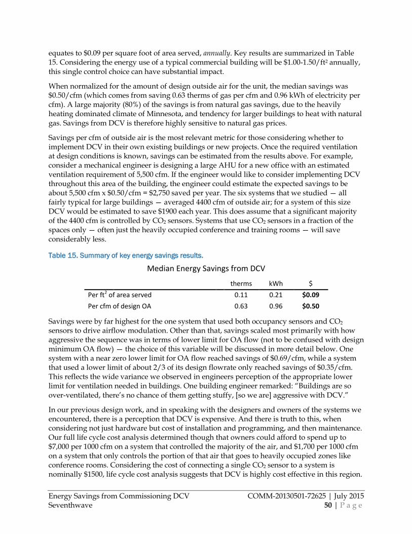
Energy Savings from Commissioning DCV COMM-20130501-72625 | July 2015 Seventhwave 50 | P a g e
equates to $0.09 per square foot of area served, annually. Key results are summarized in Table 15. Considering the energy use of a typical commercial building will be $1.00-1.50/ft2 annually, this single control choice can have substantial impact.
When normalized for the amount of design outside air for the unit, the median savings was $0.50/cfm (which comes from saving 0.63 therms of gas per cfm and 0.96 kWh of electricity per cfm). A large majority (80%) of the savings is from natural gas savings, due to the heavily heating dominated climate of Minnesota, and tendency for larger buildings to heat with natural gas. Savings from DCV is therefore highly sensitive to natural gas prices.
Savings per cfm of outside air is the most relevant metric for those considering whether to implement DCV in their own existing buildings or new projects. Once the required ventilation at design conditions is known, savings can be estimated from the results above. For example, consider a mechanical engineer is designing a large AHU for a new office with an estimated ventilation requirement of 5,500 cfm. If the engineer would like to consider implementing DCV throughout this area of the building, the engineer could estimate the expected savings to be about 5,500 cfm x $0.50/cfm = $2,750 saved per year. The six systems that we studied — all fairly typical for large buildings — averaged 4400 cfm of outside air; for a system of this size DCV would be estimated to save $1900 each year. This does assume that a significant majority of the 4400 cfm is controlled by CO2 sensors. Systems that use CO2 sensors in a fraction of the spaces only — often just the heavily occupied conference and training rooms — will save considerably less.
Table 15. Summary of key energy savings results.
Median Energy Savings from DCV
therms kWh $ Per ft2 of area served 0.11 0.21 $0.09 Per cfm of design OA 0.63 0.96 $0.50
Savings were by far highest for the one system that used both occupancy sensors and CO2 sensors to drive airflow modulation. Other than that, savings scaled most primarily with how aggressive the sequence was in terms of lower limit for OA flow (not to be confused with design minimum OA flow) — the choice of this variable will be discussed in more detail below. One system with a near zero lower limit for OA flow reached savings of $0.69/cfm, while a system that used a lower limit of about 2/3 of its design flowrate only reached savings of $0.35/cfm. This reflects the wide variance we observed in engineers perception of the appropriate lower limit for ventilation needed in buildings. One building engineer remarked: “Buildings are so over-ventilated, there’s no chance of them getting stuffy, [so we are] aggressive with DCV.”
In our previous design work, and in speaking with the designers and owners of the systems we encountered, there is a perception that DCV is expensive. And there is truth to this, when considering not just hardware but cost of installation and programming, and then maintenance. Our full life cycle cost analysis determined though that owners could afford to spend up to $7,000 per 1000 cfm on a system that controlled the majority of the air, and $1,700 per 1000 cfm on a system that only controls the portion of that air that goes to heavily occupied zones like conference rooms. Considering the cost of connecting a single CO2 sensor to a system is nominally $1500, life cycle cost analysis suggests that DCV is highly cost effective in this region.
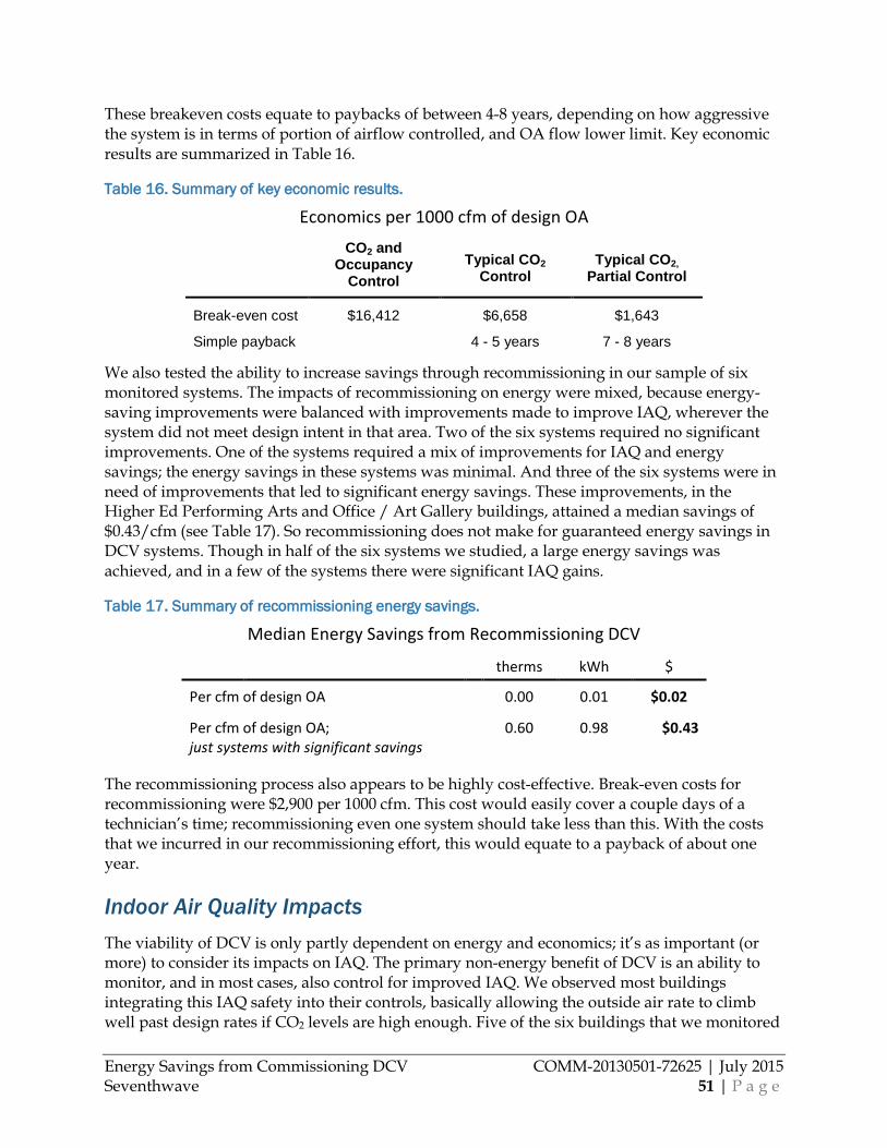
Energy Savings from Commissioning DCV COMM-20130501-72625 | July 2015 Seventhwave 51 | P a g e
These breakeven costs equate to paybacks of between 4-8 years, depending on how aggressive the system is in terms of portion of airflow controlled, and OA flow lower limit. Key economic results are summarized in Table 16.
Table 16. Summary of key economic results.
Economics per 1000 cfm of design OA
CO2 and Occupancy
Control Typical CO2
Control Typical CO2,
Partial Control
Break-even cost $16,412 $6,658 $1,643
Simple payback 4 - 5 years 7 - 8 years
We also tested the ability to increase savings through recommissioning in our sample of six monitored systems. The impacts of recommissioning on energy were mixed, because energy-saving improvements were balanced with improvements made to improve IAQ, wherever the system did not meet design intent in that area. Two of the six systems required no significant improvements. One of the systems required a mix of improvements for IAQ and energy savings; the energy savings in these systems was minimal. And three of the six systems were in need of improvements that led to significant energy savings. These improvements, in the Higher Ed Performing Arts and Office / Art Gallery buildings, attained a median savings of $0.43/cfm (see Table 17). So recommissioning does not make for guaranteed energy savings in DCV systems. Though in half of the six systems we studied, a large energy savings was achieved, and in a few of the systems there were significant IAQ gains.
Table 17. Summary of recommissioning energy savings.
Median Energy Savings from Recommissioning DCV
therms kWh $
Per cfm of design OA 0.00 0.01 $0.02
Per cfm of design OA; just systems with significant savings
0.60 0.98 $0.43
The recommissioning process also appears to be highly cost-effective. Break-even costs for recommissioning were $2,900 per 1000 cfm. This cost would easily cover a couple days of a technician’s time; recommissioning even one system should take less than this. With the costs that we incurred in our recommissioning effort, this would equate to a payback of about one year.
Indoor Air Quality Impacts The viability of DCV is only partly dependent on energy and economics; it’s as important (or more) to consider its impacts on IAQ. The primary non-energy benefit of DCV is an ability to monitor, and in most cases, also control for improved IAQ. We observed most buildings integrating this IAQ safety into their controls, basically allowing the outside air rate to climb well past design rates if CO2 levels are high enough. Five of the six buildings that we monitored
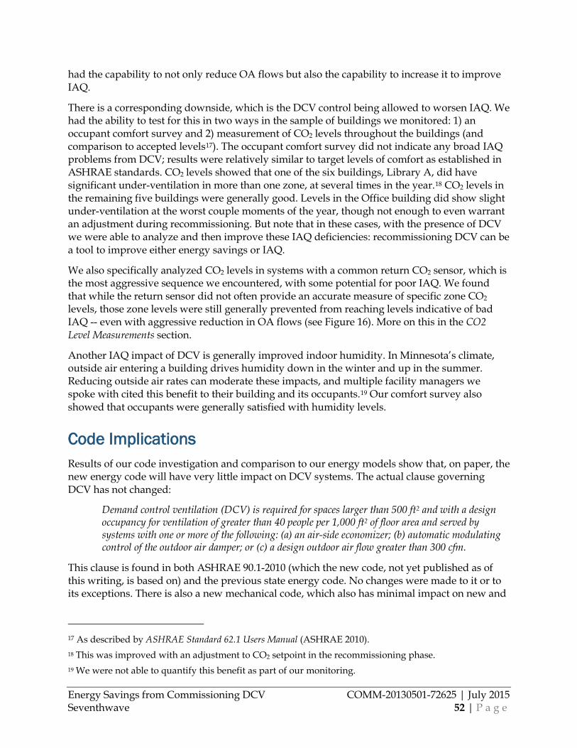
Energy Savings from Commissioning DCV COMM-20130501-72625 | July 2015 Seventhwave 52 | P a g e
had the capability to not only reduce OA flows but also the capability to increase it to improve IAQ.
There is a corresponding downside, which is the DCV control being allowed to worsen IAQ. We had the ability to test for this in two ways in the sample of buildings we monitored: 1) an occupant comfort survey and 2) measurement of CO2 levels throughout the buildings (and comparison to accepted levels17). The occupant comfort survey did not indicate any broad IAQ problems from DCV; results were relatively similar to target levels of comfort as established in ASHRAE standards. CO2 levels showed that one of the six buildings, Library A, did have significant under-ventilation in more than one zone, at several times in the year.18 CO2 levels in the remaining five buildings were generally good. Levels in the Office building did show slight under-ventilation at the worst couple moments of the year, though not enough to even warrant an adjustment during recommissioning. But note that in these cases, with the presence of DCV we were able to analyze and then improve these IAQ deficiencies: recommissioning DCV can be a tool to improve either energy savings or IAQ.
We also specifically analyzed CO2 levels in systems with a common return CO2 sensor, which is the most aggressive sequence we encountered, with some potential for poor IAQ. We found that while the return sensor did not often provide an accurate measure of specific zone CO2 levels, those zone levels were still generally prevented from reaching levels indicative of bad IAQ -- even with aggressive reduction in OA flows (see Figure 16). More on this in the CO2 Level Measurements section.
Another IAQ impact of DCV is generally improved indoor humidity. In Minnesota’s climate, outside air entering a building drives humidity down in the winter and up in the summer. Reducing outside air rates can moderate these impacts, and multiple facility managers we spoke with cited this benefit to their building and its occupants.19 Our comfort survey also showed that occupants were generally satisfied with humidity levels.
Code Implications Results of our code investigation and comparison to our energy models show that, on paper, the new energy code will have very little impact on DCV systems. The actual clause governing DCV has not changed:
Demand control ventilation (DCV) is required for spaces larger than 500 ft2 and with a design occupancy for ventilation of greater than 40 people per 1,000 ft2 of floor area and served by systems with one or more of the following: (a) an air-side economizer; (b) automatic modulating control of the outdoor air damper; or (c) a design outdoor air flow greater than 300 cfm.
This clause is found in both ASHRAE 90.1-2010 (which the new code, not yet published as of this writing, is based on) and the previous state energy code. No changes were made to it or to its exceptions. There is also a new mechanical code, which also has minimal impact on new and
17 As described by ASHRAE Standard 62.1 Users Manual (ASHRAE 2010). 18 This was improved with an adjustment to CO2 setpoint in the recommissioning phase. 19 We were not able to quantify this benefit as part of our monitoring.
Energy Savings from Commissioning DCV COMM-20130501-72625 | July 2015 Seventhwave 53 | P a g e
existing systems; code-required ventilation rates remain the same as they have for about eight years. For systems installed prior to eight years ago there would be a significant difference for upgrading to the new code. We monitored two such systems. Our models show that updating the ventilation rates in these two older systems would have a small impact due to their DCV systems already reducing ventilation rates (one of the two had essentially zero difference in usage, the other saved an additional 6% system energy with rates meeting the new code).
But the new Minnesota energy code may have more of an impact through a somewhat different mechanism: increased enforcement and compliance. Based on our conversations with many throughout Minnesota’s commercial building community, enforcement of (and as a result, compliance to some extent) the code’s DCV requirements are not common. After hearing this anecdotally from some designers and operators, we spoke with eight different code officials who review larger commercial buildings. These officials did report reviewing ventilation design in significant detail, focusing on design OA flows and whether they meet requirements. But generally they do not review controls, including any aspect of DCV. They generally do not check to see if DCV has been included where required, or to see if DCV — where implemented — is being implemented according to standards. They report being too busy reviewing code requirements related to more important items such as life safety. Said one official regarding systems meeting code: “We take the engineer’s word for it; we do not check to see what [controls] they have set up.”
The state has developed materials and events to introduce the new code to the community in 2015. This includes a website, educational materials, and planned training through various partners. Trade groups such as the American Society of Heating Cooling and Air-conditioning Engineers can generally be counted on to deliver this information to their members as well. Through these activities, it is possible that adoption of a new code is already increasing awareness of various elements of the code, including controls like DCV, as well as new ventilation rates. So though the new code may not technically change the DCV requirement it could increase awareness, and as a result, eventually compliance and energy impacts. But even with this improvement, it appears that much of the state is starting from nearly zero enforcement of DCV requirements and could benefit from additional code compliance programs and educational offerings.
We also noted that several of the systems that we observed were designed more stringently than code, often to achieve LEED certification. In the current version of LEED (v3), CO2 sensors are required to meet the credit for Outdoor Air Delivery Monitoring (IEQc1), in spaces with more than 25 people per 1000 ft2. This is much more stringent than Minnesota code. In addition, sensors must be placed in the zone itself, which precludes use of a common return sensor. Airflow measurement is also required. In the new version required later this year (v4), this does not change substantially. Note that the portions of LEED discussed above are for improved IAQ, so the credits only require that sensors be installed to monitor IAQ. Owners and engineers need to be made aware that a sequence needs to be included to modulate OA flow downward in order to yield energy savings.
Steps to Optimal Implementation of DCV Technology In addition to the quantitative data that we collected, we were able to learn a number of lessons about applying DCV. These lessons were gleaned primarily from our commissioning exercise,
Energy Savings from Commissioning DCV COMM-20130501-72625 | July 2015 Seventhwave 54 | P a g e
but also in speaking with occupants, managers, designers, owners, and manufacturers, as well as observing the systems in operation during data collection. The overarching lesson that we learned is that deciding to do DCV isn’t the most important step in saving energy. You have to do DCV correctly from start to finish, focusing especially on thorough design and then proper commissioning of the system.
There is significant existing literature on the best practices for implementing DCV. Some of the clearest guidance is available from Energy Design Resources (EDR 2007), Trane (Trane 2005) and the U.S. Department of Energy Building Technologies Program (DOE 2012). We will not attempt to summarize this literature; our learnings instead build on these documents and perhaps offer a glimpse of how their guidance plays out in the field: what is working, what is not, and what adjustments are being made or should be made. Readers who want to start with the basics should read this literature first.
Design One of our primary goals of this study was to test for a need for more commissioning of DCV systems; we have found this to be the case for many advanced control approaches. We did find need for this, but with DCV we also found that there is a significant need for improvement in design. At the very least, designers need to be more thorough with documenting the key aspects of DCV. In a number of projects we observed, a significant portion of the design work was actually done by the controls contractor during construction, rather than by an engineer or designer in the design phase. This is not ideal, because the controls contractor may or may not be qualified to make some of these decisions, and the owner has less opportunity to ensure the design meets their goals. More sophisticated multi-building owners take this a step further by actually prescribing their desired approach on all new projects.
In any case, with the number of deficiencies we found in DCV systems, in terms of both IAQ and energy savings, there is a clear need for a more thorough design to be documented by the designing engineer, and understood by both the owner and contractor prior to installation. We noticed the following items in particular missing from design documents:
• Specific sequence of control o CO2 setpoint o Outside airflow lower limit
• CO2 sensor location • Airflow measurement requirements
And as designers begin to include these elements more in their designs, they should attempt to remain consistent with existing best practices wherever possible. The basics of those practices are covered in the literature we referenced above; we build on those with additional lessons learned below.
Sequence First, it is important that the design team discuss CO2 control with the owner and agree on a framework for a sequence that meets the owner’s goals. In the characterization portion of the study, we visited a building where the CO2 system was clearly set up only as a backup IAQ mechanism. As we questioned the owner it was clear they had hoped that it would be saving
Energy Savings from Commissioning DCV COMM-20130501-72625 | July 2015 Seventhwave 55 | P a g e
them energy, which was not occurring. The relative importance of IAQ should also be discussed; the tradeoff between IAQ and energy savings is not an either/or but rather a spectrum, as we’ll demonstrate.
Recall that in Table 4 work, we encountered five main sequences in use (originally shown in Table 4 above; summarized here):
1. Direct OA flow control, return sensor. Control is based purely on a CO2 sensor in the common return of a single duct, multizone system (generally VAV).
2. Direct OA flow control. A zone-level CO2 sensor, or a few sensors, directly controls AHU OA damper (without consideration for ventilation efficiency).
3. Ventilation reset. OA damper based on a multizone reset approach, considering ventilation efficiency, etc. (resembling that recommended by ASHRAE 62.1).
4. Zone box, then OA damper. Zone-level CO2 sensors first drive their zone damper open, then the OA damper is modulated based on a central reset approach.
5. Zone minimum reset. Zone-Level ccupancy sensors are used to reset zone minimums as low as possible when zones are unoccupied. AHU then modulates SA and OA damper based on both zone boxes and zone level or return level CO2 sensors.
Designers are still heavily using sequence 1 (direct OA flow control, return sensor) and 2 (direct OA flow control) as they are simple and at the same time aggressive in terms of energy savings. Based on our energy and IAQ results, these two approaches do save considerable energy but in certain situations are exposed to potential IAQ problems in the zones that are not directly controlled by CO2 sensors. For systems where the uncontrolled zones are small in number or very small in portion of airflow, this may not be a problem and still allow for effective application of Sequences 1 or 2. This was the case with the Higher Ed Performing Arts building for example, where there were less than 10 zones with significant OA requirements, and the vast majority of air was going to the one controlled zone, which was a theater. Spaces like this could continue to use Sequence 2. More guidance on these basic sequences can be found in EDR 2007.
For other systems — especially those with a many similarly-sized zones - designers should consider jumping right to Sequence 5 (zone minimum reset), which still utilizes CO2 sensors in heavily occupied rooms like theaters and large conference rooms, but covers the remaining zones with inexpensive, easy to maintain occupancy sensors. The CO2 sensors communicate a variable occupancy signal to their VAV box and the central AHU, while the occupancy sensors communicate a simple binary (occupied/unoccupied) signal to their VAV box (with the additional benefit that they can shut the VAV box entirely when a room is unoccupied). Occupancy sensors are especially inexpensive when the bulk of their cost is already justified by use for lighting controls. Sequence 5 is emerging as a new best practice, and was specifically identified as the best approach in a recent ASHRAE-sponsored study using simulation-based analysis of all likely sequences (Trane 2005). This sequence was used in the best performing system in our sample of six, the Office / Art Gallery; it saved 58% more energy cost than the next best system. At one higher education campus we visited, the facility staff were in the process of converting every building on campus to Sequence 5, after initial trials showed performance gains with lower maintenance. A consensus best practice has not yet been established on Sequence 5, but the best engineering guidance so far was given in Taylor 2014.
Energy Savings from Commissioning DCV COMM-20130501-72625 | July 2015 Seventhwave 56 | P a g e
This approach would ‘leapfrog’ sequences 3 (ventilation reset) and 4 (zone box, then OA damper). These two sequences have been considered best practice as they assure proper IAQ, but these approaches require a significant number of CO2 sensors for aggressive energy savings, adding first cost and maintenance. Library A used sequence 4 with some success, but they had many CO2 sensors, one each in the majority of all their VAV zones, and reported higher sensor replacement rates than any of the other monitored sites. These sequences could still be used by an owner interested in maximizing IAQ; they provide excellent control of IAQ and do deliver energy savings. It should be noted that Sequence 4 may provide a slight energy savings advantage due to its modulation of the VAV box prior to increasing outside air; Library A switched from Sequence 3 to 4 after a year of occupancy to take advantage of this benefit. More guidance on Sequence 3 can be found in Trane 2005; Sequence 4 is just a slight adjustment added to this.
Finally, in this cold climate the sequence should include consideration for freeze protection and sizing of hot and chilled water coils in the air handling units. This generally means having a maximum limit for the outdoor airflow rate and if this rate is greater than the design value, it should decrease to or nearly to the design value when temperatures outside reach points considerably below freezing. Most air handling unit and coil designs are going to consider both sizing and freeze concerns for the design OA airflow and not some greater flow just due to DCV. We made this adjustment during our commissioning effort at the Performing Arts Center for example; prior to that the facility manager was simply manually adjusting the setpoints when temperatures outside were below about 20oF.
CO2 setpoint. The designer should also determine and document the desired CO2 setpoint, or setpoints, depending on sequence. The literature generally defines two approaches to setting CO2 setpoints: proportional (which ramps between two setpoints) and single setpoint control (Trane 2005). Single setpoint is simpler but somewhat more aggressive (tends toward under-ventilation); this was used by all but one of our six monitored systems. Both approaches do require an upper CO2 setpoint, or limit, that the sequence avoids exceeding. The higher the setpoint, the greater the energy savings (but at the same time, the greater the risk of IAQ issues if not chosen properly). The average building we encountered had a CO2 setpoint of 950 ppm. Most buildings chose a nominal value near this, like 900 or 1000 ppm. A more precise setpoint can be determined using a straightforward equation from the ASHRAE 62.1 User’s Manual, in Appendix A. Using this equation, many of the spaces we encountered — and probably most across Minnesota — could consider raising their CO2 setpoint, increasing savings. Setpoints for a typical classroom in urban area of Minnesota can be 1050 ppm, and setpoints for a dining space could be over 1500 ppm.
Outside Airflow Lower Limit. Perhaps an even more crucial item for DCV design is the choice of an OA flow lower limit. This is simply the lowest flow that the system is allowed to decrease to through the use of CO2 control. This can range from 0 cfm in the most aggressive systems, to the design level of OA in a system using CO2 control only to ensure IAQ. The systems we monitored ranged from 0 cfm to about 55% of design OA flow. It’s important for the designer to understand the owner’s goals for DCV, and choose a lower limit accordingly. As can be imagined, the lower limit is a major driver in how much energy DCV can save.
The literature offers options but no consensus best-practice on what the lower limit should be for setting CO2 systems. Many recommend the area-weighted ventilation portion of ventilation in ASHRAE 62.1 (called Ra); this is most common in the literature but does not seem common in
Energy Savings from Commissioning DCV COMM-20130501-72625 | July 2015 Seventhwave 57 | P a g e
practice, where nominal %-OA values are most popular. Notably, one of the systems in our study that chose 0% as the lower limit stated that it’s nearly impossible for most OA dampers — especially for older ones — to actually reach zero OA flow. Damper leakage inevitably allows some significant OA into the system.
Interestingly, one multi-building owner commented that though they have learned some lessons regarding both CO2 and lower limit setpoints, they still must rely on their designer’s recommendation for these values because there is liability involved for such a choice due to impacts on IAQ and occupant health.
Our sample of systems was not large enough to suggest a specific outside airflow lower limit. Zero is allowed by most code officials we spoke with, but is probably not a best practice for all systems due to its potential impacts on IAQ. On the other hand, setting the lower limit equal to 50% or more of design OA airflow — which some of our systems had — is clearly more than is necessary. Using the area component (usually called Ra) of code or ASHRAE Standard 62.1 requirements is the default choice of many engineers, and has been accepted by many code officials.
On a final note, pressure relationships also need to be considered when setting the lower limit. This should obviously include consideration for room exhaust air (e.g. restroom exhaust), but also pressurization relationships between spaces and between spaces on the outdoors. Based on the simple test of ease of opening doors, we did not witness any significant pressure relationship problems in our six monitored systems, even with aggressive DCV. This is partly because these systems operated at non-zero OA flow for the vast majority of the time, and did not contain large exhaust streams.
CO2 Sensor Location We found that, even though they should, designers don’t always lay out the exact position of the CO2 sensors in the building. The biggest decision to be made is whether the CO2 sensor should be located in the zone itself, or in the return airstream.
Locating a single CO2 sensor in the common return of a multizone VAV system is the least expensive approach, though it does not always ensure proper IAQ. We specifically analyzed CO2 levels in systems with a common return air CO2 sensor. We found that the return sensor often did not provide an accurate measure of specific zone CO2 levels (see Figure 16). However, those zone levels were still generally prevented from reaching levels indicative of bad IAQ - even with aggressive reduction in OA flows. This indicates that CO2 sensors in a common return may only be warranted when that return primarily serves one large space (such as a library), and the other spaces are either small or given their own CO2 sensor (as either a safety or additional control). An alternative option would be a common return sensor with a very conservative (CO2) setpoint, as a very inexpensive DCV approach; this would be viable in a VAV system with a smaller number (e.g. 10) of zones.
If a common return approach is considered, local code officials should be consulted. Due to its IAQ risks, some code officials will only allow the approach under certain circumstances; each circumstance must be argued individually. However, the majority of the code officials we spoke with accepted CO2 sensors in the return under all circumstances. It should also be noted that
Energy Savings from Commissioning DCV COMM-20130501-72625 | July 2015 Seventhwave 58 | P a g e
most code officials also admitted not having time or resources to check CO2 sensor location anyway.
In all other cases, the CO2 sensor should always be located in the zone itself, in a well-mixed area at a height of about six feet (EDR 2007). Multiple sensors can be used in a given zone to mitigate sensor drift, though we did not observe many instances of this approach. If some type of calibration is used coupled with BAS alarms for high CO2 levels, a single sensor seems to work well.
Airflow Measurement Demand control ventilation operation should not depend only on input from CO2 sensors. Best practices dictate that the OA flow also be measured directly (in order to control the rate). Further, this measurement is best done through an airflow measurement station (AFMS) using thermal dispersion sensors, with horizontal probes (Fisk 2009a). Five of the six systems we monitored used this type of measurement, and comparisons with other flow measurement stations and energy balances (see Data Accuracy) indicated that these sensors were performing accurately most of the time, and over a range of airflows. This was more accurate than correlation to damper position, which the remaining system used.
In addition to specifying a thermal dispersion AFMS (which, though common in our small sample, is not as common in general practice) it is important for the designer to provide a ducted intake to this AFMS that is long enough and straight enough to meet manufacturer’s requirements.20
At the Office / Art Gallery site, the designer added an additional element to improve AFMS accuracy. AFMS are inherently less accurate at lower air velocities. But OA intakes are generally sized for economizer flow, which means that the OA flows — and therefore velocities — are relatively low whenever the DCV is active instead of the economizer. As a result, the designer at this particular site included two OA intakes: 1) one for economizer mode, and 2) one for minimum OA flow, or whenever DCV is active. This allows the ductwork in the second intake to be substantially smaller than in the first, and therefore air velocities are still high even when flow is small because the economizer is off. This creation of two separate intakes should be a best practice.
Other Design Considerations In addition to the primary elements covered above, there are a few additional lessons learned that designers can take away from the systems that we studied:
• Each area that we observed with DCV only occasionally reached its peak OA airflow due to CO2 levels, due to diversity. If a VAV system has enough different zones with DCV, the sizing of the heating and cooling plant (and possibly coils) could certainly be reduced due to this diversity. In sizing air handling units and coils, most designers already account for diversity in zone loads, but this suggests they should also be
20 As a general order of magnitude: one manufacturer recommends 3 duct diameters downstream of any unvaned elbows, and 1.5 diameters downstream of size transitions.
Energy Savings from Commissioning DCV COMM-20130501-72625 | July 2015 Seventhwave 59 | P a g e
accounting for diversity in OA load. This could improve the economics of DCV further. (Note that this would not be applicable to buildings where all the densely occupied zones tend to peak at the same time, such as a convention center.)
• In instances with multiple, 100% OA makeup air units that serve the same space (sometimes as a “ganged” approach, sometimes as separate units) consider using DCV to shut down entire AHUs rather than modulating flow.
• Regardless of the use of CO2 sensors, or control of OA dampers, occupancy sensors can lead to substantial additional energy savings just in control of VAV boxes. If already installed for lighting control, this should yield very short paybacks.
• From the variety of approaches and degrees of aggressiveness that we observed, it should be noted that including DCV in a project is not a “yes or no” proposition for a designer. Though the ideal system may have a CO2 sensor in most spaces all tied to central control of the AHU, there are steps that can be taken to simplify and reduce cost if this ideal approach is too much: less zones can be controlled, occupancy sensors can be used in all smaller rooms, VAVs that serve multiple rooms may use a single common sensor, or single CO2 sensors can be included in return ducts for large spaces. And each reduction in use of a CO2 sensor does reduce maintenance cost.
In general, there is still significant variation in DCV design approaches in Minnesota, and many of the approaches are far from best practice. Research and technology transfer efforts could therefore focus more on methods to make the current best practices more adoptable and adopted, and less on trying to optimize the best practices themselves.
Installation (hardware) Being a control-based energy savings measure, there is a small amount of hardware involved in installation. We found that installation was completed appropriately when the design was properly documented. Equipment was installed in the correct place, and connected correctly. There were two issues that the owners we spoke with did encounter. First, most CO2 sensors now come with an automated calibration sequence (often called ABC, ABS, etc. by the manufacturer). This sequence automatically recalibrates the sensor based on the lowest CO2 reading observed over time. But some spaces — particularly in Library A, out of the systems we observed — never actually return to an ambient CO2 level because the unoccupied period in the space is too short. If unoccupied periods will be only a few hours long (or non-existent) then automated calibration should be deactivated. This often needs to be done on the sensor hardware itself and cannot be done via software. At times, it is hard-wired at the factory; the contractor ordering the hardware should be aware of this “no auto-calibration” option. Ideally, designers should specify this if necessary, so the contractor can select the sensor appropriately.
In sequences that utilize occupancy sensors for control of VAV boxes (as in Sequence 5 above), use of occupancy sensors that also control lighting does introduce a cross-trade connection involving both the mechanical (or controls) and electrical contractor. The responsibilities here need to be spelled out more clearly, as they would be with electrical wiring to other mechanical devices. Specifically, contractors must understand where electrical work ends, and what signal needs to be available at that connection point. In one building we characterized this had not been well documented and so the connection was initially not made properly. It had to be fixed after the fact with urging from a commissioning authority (of which one was luckily employed on this particular project).
Energy Savings from Commissioning DCV COMM-20130501-72625 | July 2015 Seventhwave 60 | P a g e
Controls Programming (and M&V) Setup and coding of the DCV sequence can also be relatively straightforward if the design is well documented and the sequence written by the designer. Many owners (and a few contractors) did inform us that the mechanical designer did not document a specific sequence, and this work fell to the controls contractor or even the manufacturer. In the six buildings that we monitored, two had complete DCV designs from the mechanical designers, and one had a mostly-complete design that still required some design by the owner and contractor.
In cases where the design is not fully complete and especially where it does not include a sequence, controls contractors and manufacturers programming their own DCV sequences should refer to the best practices and lessons learned described in the Design section above.
We did learn a couple other lessons from our monitoring work that apply directly to contractors who program DCV systems:
• The OA flow and all CO2 levels should be output to the BAS, and if possible made available on a DCV summary screen for operators to check.
• Facility managers find it very helpful when some thought is given to programming alarms that will help them maintain effective operation of the system. Alarms should alert that a sensor has drifted below a reasonable level (ambient CO2 concentration), notify when a reading is above an acceptable level for a period of time, and notify when a scheduled calibration is due.
• In one system that did not have a complete design, the designer had at least specified an AFMS to measure OA flow at the intake. The contractor made a judgement that the AFMS was not adequately placed to measure airflow, and instead programmed the DCV sequence to modulate based on OA damper position (correlated to flow by the balancer).
Operation (and occupant behavior) In our observations, the design, installation, and commissioning of a system were the most important steps to proper performance. But the operation of the system by facility management, and the use of the space by occupants, did have some impact. The biggest area for improvement that we observed is in the handover from the design and construction team to the operator of the facility. Important elements of handover should include:
• Proper training. Multiple owners that we spoke with stated that the DCV was a particular item that they did not receive adequate training on. As a result they were not certain exactly what they needed to do to keep the DCV operating properly, and relied too heavily on bringing the contractor back to fix problems.
• CO2 sensor location and reporting. The operator should know where all the CO2 sensors are, and these should be clearly reported on their BAS interface. One facility manager that we spoke with in a characterization visit didn’t even know they had CO2 sensors until we pointed it out. (Needless to say, he was not satisfied with his amount of involvement in the design and construction phases of the project.)
• DCV will generally be a low priority, both for commissioning and ongoing operation. As a result, if there is any hint of a comfort issue, it may be the first control disabled, especially if an operator has not been trained on how it works or why it’s important for energy efficiency.
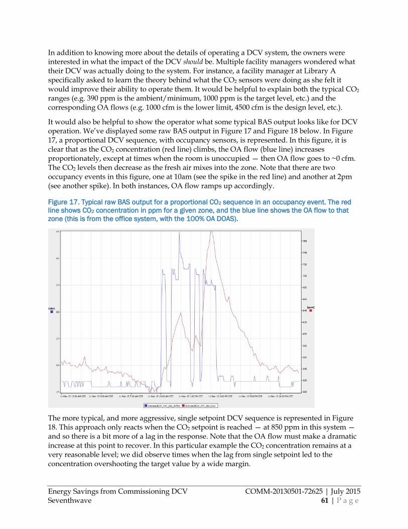
Energy Savings from Commissioning DCV COMM-20130501-72625 | July 2015 Seventhwave 61 | P a g e
In addition to knowing more about the details of operating a DCV system, the owners were interested in what the impact of the DCV should be. Multiple facility managers wondered what their DCV was actually doing to the system. For instance, a facility manager at Library A specifically asked to learn the theory behind what the CO2 sensors were doing as she felt it would improve their ability to operate them. It would be helpful to explain both the typical CO2 ranges (e.g. 390 ppm is the ambient/minimum, 1000 ppm is the target level, etc.) and the corresponding OA flows (e.g. 1000 cfm is the lower limit, 4500 cfm is the design level, etc.).
It would also be helpful to show the operator what some typical BAS output looks like for DCV operation. We’ve displayed some raw BAS output in Figure 17 and Figure 18 below. In Figure 17, a proportional DCV sequence, with occupancy sensors, is represented. In this figure, it is clear that as the CO2 concentration (red line) climbs, the OA flow (blue line) increases proportionately, except at times when the room is unoccupied — then OA flow goes to ~0 cfm. The CO2 levels then decrease as the fresh air mixes into the zone. Note that there are two occupancy events in this figure, one at 10am (see the spike in the red line) and another at 2pm (see another spike). In both instances, OA flow ramps up accordingly.
Figure 17. Typical raw BAS output for a proportional CO2 sequence in an occupancy event. The red line shows CO2 concentration in ppm for a given zone, and the blue line shows the OA flow to that zone (this is from the office system, with the 100% OA DOAS).
The more typical, and more aggressive, single setpoint DCV sequence is represented in Figure 18. This approach only reacts when the CO2 setpoint is reached — at 850 ppm in this system — and so there is a bit more of a lag in the response. Note that the OA flow must make a dramatic increase at this point to recover. In this particular example the CO2 concentration remains at a very reasonable level; we did observe times when the lag from single setpoint led to the concentration overshooting the target value by a wide margin.
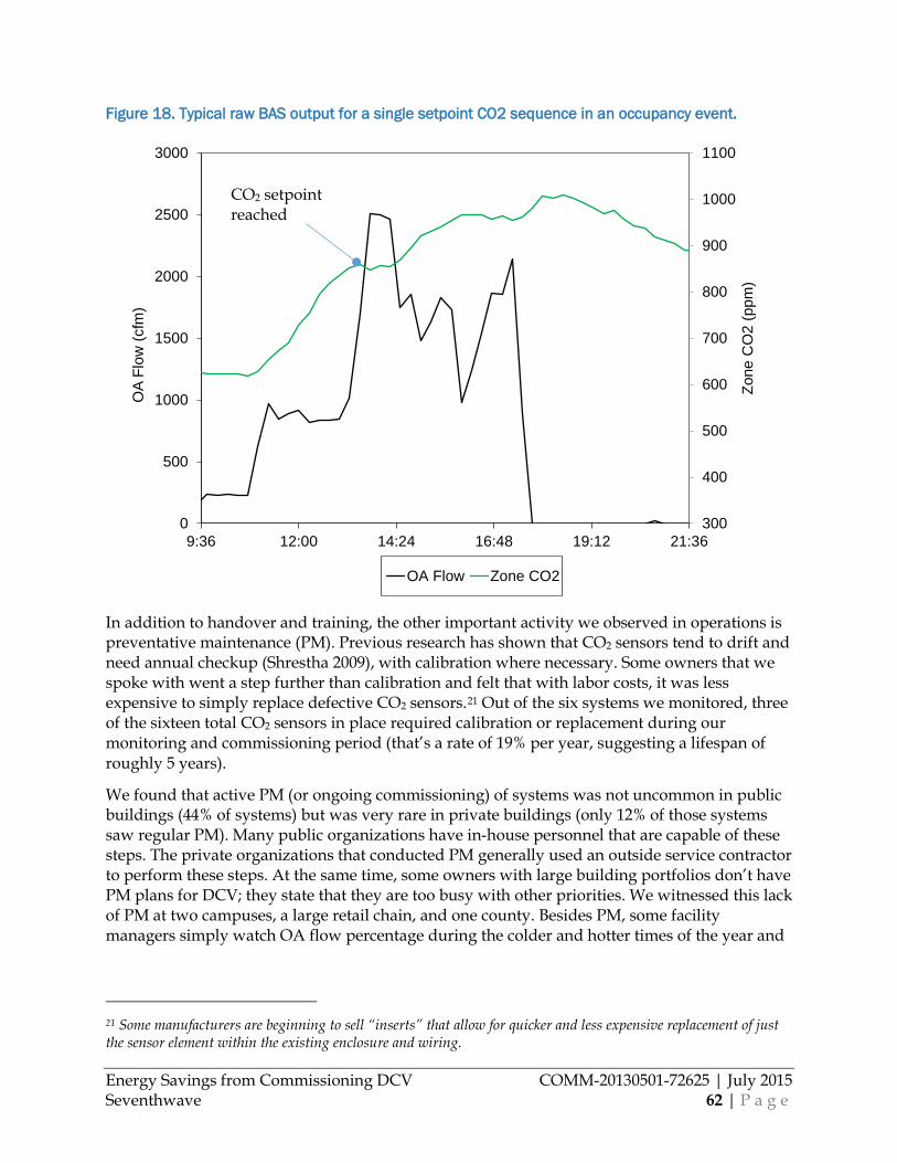
Energy Savings from Commissioning DCV COMM-20130501-72625 | July 2015 Seventhwave 62 | P a g e
Figure 18. Typical raw BAS output for a single setpoint CO2 sequence in an occupancy event.
In addition to handover and training, the other important activity we observed in operations is preventative maintenance (PM). Previous research has shown that CO2 sensors tend to drift and need annual checkup (Shrestha 2009), with calibration where necessary. Some owners that we spoke with went a step further than calibration and felt that with labor costs, it was less expensive to simply replace defective CO2 sensors.21 Out of the six systems we monitored, three of the sixteen total CO2 sensors in place required calibration or replacement during our monitoring and commissioning period (that’s a rate of 19% per year, suggesting a lifespan of roughly 5 years).
We found that active PM (or ongoing commissioning) of systems was not uncommon in public buildings (44% of systems) but was very rare in private buildings (only 12% of those systems saw regular PM). Many public organizations have in-house personnel that are capable of these steps. The private organizations that conducted PM generally used an outside service contractor to perform these steps. At the same time, some owners with large building portfolios don’t have PM plans for DCV; they state that they are too busy with other priorities. We witnessed this lack of PM at two campuses, a large retail chain, and one county. Besides PM, some facility managers simply watch OA flow percentage during the colder and hotter times of the year and
21 Some manufacturers are beginning to sell “inserts” that allow for quicker and less expensive replacement of just the sensor element within the existing enclosure and wiring.
300
400
500
600
700
800
900
1000
1100
0
500
1000
1500
2000
2500
3000
9:36 12:00 14:24 16:48 19:12 21:36
Zone
CO
2 (p
pm)
OA
Flow
(cfm
)
OA Flow Zone CO2
CO2 setpoint reached
Energy Savings from Commissioning DCV COMM-20130501-72625 | July 2015 Seventhwave 63 | P a g e
check to see that CO2 sensors aren’t unnecessarily increasing OA flow; with this approach they can at least detect sensors/sequences that drift out of calibration in the upward direction.
Energy Modeling
Energy modeling is an additional step that is often included throughout the design and, increasingly so, even into installation and operation of a system. As DCV includes complex interactions with occupants, building loads, the climate, and other controls such as economizer and SAT reset, a full system energy model is the best, and possibly only thorough, method for designers or owners to evaluate DCV for their prospective projects.
In doing the energy modeling for this project, we chose EnergyPlus to conduct the entirety of our DCV modeling (though we did create the geometry and basic HVAC framework in DesignBuilder, to save time). We have found that other common option, DOE2.2/eQUEST, has considerable shortcomings in modeling DCV for many system types. In implementing DCV in EnergyPlus we utilized the Controller:MechanicalVentilation object in concert with ZoneControl:ContaminantController objects in each zone controlled by DCV. We found the IndoorAirQualityProcedure method to be most effective at representing the systems we observed. Other inputs that were critical to accurately capturing DCV operation included Minimum Limit Type, Economizer Minimum Limit Dry-Bulb temperature, BS Minimum Outdoor Air Flow Rate, all of which are in the Controller:OutdoorAir object. A detailed description of our entire system modeling methodology can be found in the Whole Building Energy Model section.
Commissioning or Recommissioning A thorough commissioning process includes involvement from the conception of a project, through design, into initial operation of the building (or later). We focused our efforts and this research in general on the steps that take place at the end of design to the beginning of occupancy, since these are the elements that we are still able to impact today. Though what we completed is technically “recommissioning”, the lessons we learned in both that activity and our general monitoring are just as applicable to “commissioning” of new systems, at least the parts of commissioning that occur directly after construction. Our recommissioning effort is described in the greatest detail in the Recommissioning Process section earlier in this report, which is supplemented by Appendix C: Recommissioning Checklist, where a full checklist of CO2 DCV commissioning steps can be found. Practitioners who are undertaking commissioning or recommissioning of CO2 DCV systems should read these sections.
Based on the deficiencies that we found in our study, and on those that reportedly existed prior to the study, the following commissioning steps seem to be the most critical to ensuring a system that functions properly:
• During design, verify that designer has included the five elements that we listed in the Design section: 1) sequence, 2) CO2 setpoint, 3) OA flow lower limit, 4) sensor location(s), and 5) airflow measurement. Recheck each of these five at installation
• After installation, verify that CO2 sensors are calibrated with a brief check of each. • Upon occupancy, use the BAS to verify that the system performs according to sequence
for at least a week of operation, and at least one significant occupancy event in each
Energy Savings from Commissioning DCV COMM-20130501-72625 | July 2015 Seventhwave 64 | P a g e
controlled space. This can be done remotely, and can be more effective than a single system performance test since it covers more scenarios.
o Check for rogue single zones driving the entire systems OA flow. o Check the schedule of the OA damper (note that this can be different than the fan
schedule). Consider scheduling the OA damper to only open once a significant number of people arrive in the morning, rather than simply basing it on the time when the thermostat changes to “occupied”. In schools for example, when staff may arrive an hour or more before the students fill the building.
• Finally, ensure that the owner is trained, and understands both what the sensors should do, and why they should do that.
Expanding and Improving CIP Offerings This study shows that savings from DCV are strong, with attractive economics that should meet benefit-cost tests for any program. We estimate that DCV has the potential to save 120 million therms and 182 million kWh annually for the State of Minnesota, which has a value of $103 million to the state’s commercial customers. Building energy codes — especially with the advent of new codes in 2015 —already capture some of this savings, requiring DCV in large commercial spaces with high peak occupancy, such as conference rooms, training rooms, and gymnasiums. There is of course significant potential beyond this for space types and system sizes not covered by code. A portion of the remaining potential is already being pursued within the state’s Conservation Improvement Program (CIP), but there is significant area for expansion with this technology. In addition, existing programs are extremely basic prescriptive approaches, and could be improved. The following four opportunities outline potential areas for expansion or improvement of DCV program offerings in Minnesota’s CIP.
Opportunity #1: New DCV systems and system retrofits Currently, the most popular offering within CIP promoting DCV is to incentivize new or retrofit projects via prescriptive incentives. For example Xcel and several cooperatives provide prescriptive incentives on the order of $10-20/ton for rooftop units with economizers tied to CO2 sensors. In addition many utilities are willing to consider DCV for a custom incentive, for non-packaged equipment, new construction, or other scenarios. Our results indicate that savings are robust and cost-effective; so existing programs should be maintained. But we have several suggestions for improving these programs. Utilities who have not been regularly incentivizing DCV should consider adding an offering based on these practices.
Prescriptive Program Option • Prescriptive incentives generally see the biggest uptake for a relatively simple,
established technology like DCV, so utilities should have a prescriptive DCV offering.
• Prescriptive incentives should be offered per cfm of design OA flow in a given system. Many current offerings pay incentives based on tons of peak cooling for the system. Basing incentives on OA flow instead would increase incentives for systems with more than a typical percentage of OA, and focus incentives more on systems that benefit most. Program designers can use the savings documented in this report to scale their incentives rates.
Energy Savings from Commissioning DCV COMM-20130501-72625 | July 2015 Seventhwave 65 | P a g e
• Basing incentives on OA flow also allows for systems other than packaged rooftop units to be incentivized, expanding the reach of these programs substantially
• Actual savings are increased by 1) proper setting of an OA lower limit, 2) a separate schedule for the OA damper, and 3) 3rd party commissioning. These should at least be documented, and potentially one or more of them verified, for incentives to be paid. Alternatively a bonus incentive could be given for completing them.
Custom Program Option • Custom incentives could be offered for any system (including almost all HVAC
system types) that is not already required by code. Savings should be calculated based on OA flow controlled by DCV.
• Custom programs could continue to follow the State of Minnesota Technical Reference (TRM) Manual for CIP, but those calculations should be adjusted. First, applicability of the manual should be expanded beyond just unitary equipment. And second, savings factors can be modified based on the results found in our study. We calculated savings for our six monitored sites based on the TRM, and found that the savings factors are primarily in need of adjustment. Heating savings factors (SF_H) should be increased by 56%, and cooling savings factors (SF_C) should be decreased by 55% (these changes are applicable to all systems except warehouses, health care, and lodging, for which our results are not applicable).
• Actual savings are increased by 1) proper setting of an OA lower limit, 2) a separate schedule for the OA damper, and 3) 3rd party commissioning. The first two items should be documented as part of the custom calculation submittal; a bonus incentive could be potentially be given for the third item.
Other Considerations • DCV is primarily a heating energy savings measure in this climate, so heating
fuel type is an important consideration. With the majority of larger buildings being gas-heated, natural gas utilities should be the first to offer incentives for DCV.
• Verification of DCV savings is complex, and ideally would require field monitoring of several points, and a calculation similar to the analysis in this study performed (see the Air Handling Unit section). Alternatively, natural gas savings may be significant enough that pre- and post-treatment utility bills could be compared, with normalization for weather, if the AHU’s energy consumption is a significant enough end use in the building. Electricity savings will not be verifiable this way, and would require detailed field monitoring.
Outreach. Candidates for these programs should be targeted based heavily on OA flows — the higher the rate of OA, the more savings potential exists. Variability in OA flow is also a consideration. Good candidates will include (but are not limited to) jail cells, classrooms, libraries, retail, light manufacturing, reception areas, open offices, and public buildings. These spaces have the necessary airflow characteristics, without being required by code to have DCV.
Energy Savings from Commissioning DCV COMM-20130501-72625 | July 2015 Seventhwave 66 | P a g e
For retrofit of existing systems, code-required spaces such as lecture halls, auditoriums, and athletic spectator areas are good candidates in addition to those above.
Opportunity #2: Recommissioning Existing DCV systems should be targeted by recommissioning, retrocommissioning, and building tune-up programs, as there is evidence that a significant number of existing systems are not living up to potential. Economics of recommissioning these systems are robust; our life cycle cost analysis showed that costs of as high as $2900 per 1000 cfm of OA were justified. Most such programs would operate well under this cost.
Regardless of the type of program (e.g. retrocommissioning, HVAC tune-up, etc.), the implementation for DCV would look about the same. Implementers can follow the guidance throughout this report, and especially the DCV commissioning checklist that we’ve developed, attached in Appendix C: Recommissioning Checklist. The energy savings described in the Savings from Commissioning section can guide program design or be used to benchmark existing incentive estimates. Those programs offered by gas utilities should especially consider targeting of DCV measures, as savings are most substantial in heating mode.
Outreach. Candidates for recommissioning would include buildings with higher design OA flows first (see the list in Opportunity #1). For recommissioning, building types that don’t tend to have as much facility management personnel should be further prioritized as they are less likely to be maintaining or improving their systems. These could include K-12 schools, municipality-owned buildings, and retail.
Programs should consider including a brief scoping-level look at BAS data as part of outreach (some retrocommissioning programs include this preliminary step). In this step, implementers should observe the OA flow, or damper position, in any period of a few days when the economizer is not providing full cooling — so either hot days in summer, or very cold days in winter. It should be quick and easy to determine whether the DCV is working properly (Figure 19, blue curve) or not working (Figure 19, red curve). It may seem obvious, but note that this can be diagnosed quickly without any type of algorithm, model, or special plot.
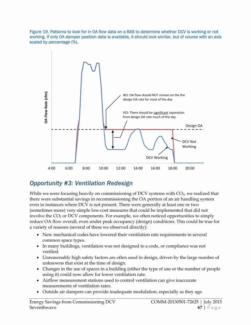
Energy Savings from Commissioning DCV COMM-20130501-72625 | July 2015 Seventhwave 67 | P a g e
Figure 19. Patterns to look for in OA flow data on a BAS to determine whether DCV is working or not working. If only OA damper position data is available, it should look similar, but of course with an axis scaled by percentage (%).
Opportunity #3: Ventilation Redesign While we were focusing heavily on commissioning of DCV systems with CO2, we realized that there were substantial savings in recommissioning the OA portion of an air handling system even in instances where DCV is not present. There were generally at least one or two (sometimes more) very simple low-cost measures that could be implemented that did not involve the CO2 or DCV components. For example, we often noticed opportunities to simply reduce OA flow overall, even under peak occupancy (design) conditions. This could be true for a variety of reasons (several of these we observed directly):
• New mechanical codes have lowered their ventilation rate requirements in several common space types.
• In many buildings, ventilation was not designed to a code, or compliance was not verified.
• Unreasonably high safety factors are often used in design, driven by the large number of unknowns that exist at the time of design.
• Changes in the use of spaces in a building (either the type of use or the number of people using it) could now allow for lower ventilation rate.
• Airflow measurement stations used to control ventilation can give inaccurate measurements of ventilation rates.
• Outside air dampers can provide inadequate modulation, especially as they age.
4:00 6:00 8:00 10:00 12:00 14:00 16:00 18:00 20:00
OA
Flow
Rat
e (c
fm)
DCV NotWorking
DCV Working
Design OA
NO: OA flow should NOT remain on the the design OA rate for most of the day
YES: There should be significant seperationfrom design OA rate much of the day
Energy Savings from Commissioning DCV COMM-20130501-72625 | July 2015 Seventhwave 68 | P a g e
A ventilation redesign program could consider all these factors, recalculate the OA flow at design conditions based on what is now known about the building (and the code) and generally save a substantial portion of OA flow and resulting heating and cooling energy.
And in addition to adjusting the flow rate, such a redesign program could ensure that OA dampers are controlled independently of temperature setpoints. We generally found that both the dampers and setpoints had the same occupied/unoccupied schedule, though modern BAS’s will often allow for two separate schedules. Adjusting the OA damper schedule independently would usually lead to substantially less hours of ventilation.
Outreach. Candidates for ventilation redesign would include: buildings with systems installed prior to 2007 (two codes ago), those with airflow measurement stations, and those who have undergone changes of use in some spaces. All three of these represent significant potential for simple but effective adjustments. In addition, further priority should be given to buildings that are older or that have less facility management personnel.
Opportunity #4: More Effective Trade Allies Trade allies are an important stakeholder in most CIP programs, including all those suggested here. DCV should be promoted further with trade allies who could participate in any of the program offerings mentioned above. In this case, trade allies include mechanical contractors, design engineers, energy consultants, and re-/retro-commissioning implementers. Though DCV has been around for some time, it is still new to many owners and even designers, and further awareness is needed.
Once awareness is established, trade allies could use additional training, primarily in design, installation, and recommissioning of DCV systems. In Steps to Optimal Implementation of DCV Technology, we covered potential best practices that each of the disciplines could employ. Specific training could be developed to disseminate these practices throughout the state. As a start, this report will be supplemented by a how-to video that will be created specifically to meet this training need. This will be disseminated publically through multiple channels.
Hands-on training may be needed for field disciplines who are working with equipment, partially due to the large variation of sensors and BASs available. Field personnel who are installing, commissioning, or recommissioning DCV systems should be able to measure CO2 concentrations in a space, calibrate a CO2 sensor, interpret BAS data on OA flow and CO2 concentration, and communicate with controls contractors that use a variety of BAS products.
Reference materials could also be developed based on this report, as well as the current best practices that this work builds on and augments. A design guide explaining, in detail, 1) what is covered in a good design, and 2) effective DCV sequences.
Example Programs There are a number of existing energy efficiency programs that offer incentives for installing DCV. Table 18 provides an overview of some programs that are offered in cold climates like Minnesota’s.
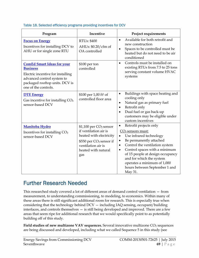
Energy Savings from Commissioning DCV COMM-20130501-72625 | July 2015 Seventhwave 69 | P a g e
Table 18. Selected efficiency programs providing incentives for DCV
Program Incentive Project requirements
Focus on Energy Incentives for installing DCV to AHU or for single zone RTU
RTUs: $400 AHUs: $0.20/cfm of OA controlled
• Available for both retrofit and new construction
• Spaces to be controlled must be heated but do not need to be air conditioned
ComEd Smart Ideas for your Business Electric incentive for installing advanced control system to packaged rooftop units. DCV is one of the controls.
$100 per ton controlled
• Controls must be installed on existing RTUs from 7.5 to 25 tons serving constant volume HVAC systems
DTE Energy Gas incentive for installing CO2 sensor-based DCV
$100 per 1,00 ft2 of controlled floor area
• Buildings with space heating and cooling only
• Natural gas as primary fuel • Retrofit only • Dual fuel or gas back-up
customers may be eligible under custom incentives
Manitoba Hydro Incentives for installing CO2 sensor-based DCV
$1,100 per CO2 sensor if ventilation air is heated with electricity $550 per CO2 sensor if ventilation air is heated with natural gas
• Retrofit projects only
CO2 sensors must: • Use infrared technology • Be permanently attached • Control the ventilation system • Control spaces with a minimum
of 15 people at design occupancy and for which the system operates a minimum of 1,000 hours between September 1 and May 31.
Further Research Needed This researched study covered a lot of different areas of demand control ventilation — from measurement, to understanding commissioning, to modeling, to economics. Within many of these areas there is still significant additional room for research. This is especially true when considering that the technology behind DCV — including IAQ sensing, occupant/building interfaces, and controls themselves — is still being developed and improved. There are a few areas that seem ripe for additional research that we would specifically point to as potentially building off of this study.
Field studies of new multizone VAV sequences. Several innovative multizone CO2 sequences are being discussed and developed, including what we called Sequence 5 in this study (see
Energy Savings from Commissioning DCV COMM-20130501-72625 | July 2015 Seventhwave 70 | P a g e
While Figure 4 depicts the types of buildings that we studied, it also depicts, to a lesser extent, the ways that CO2-based DCV is used in non-packaged systems in Minnesota. But it is worth noting that our sample is not random, and therefore cannot be directly extrapolated to the larger state population. The nature of seeking buildings for in-depth study has probably biased this sample more toward public buildings, and for similar reasons toward buildings that have a more hands-on management. For example, in the second bar in the figure, we report the amount of commissioning that was described to us for each system; the fact that 80% of the controls saw a dedicated commissioning effort is somewhat higher than we’d predict for the average Minnesota system based on anecdotal evidence. This would suggest that our savings estimates for additional savings available from recommissioning are conservative.
Control Sequences Encountered), as well as sequences that utilize CO2 sensing in the supply air (Taylor 2014). The vast majority of the research in this area so far has been via simulation. Based on our observations, simulation without field measurement is of very limited use in evaluating these new sequences. Simulation has significant shortcomings representing actual variation in occupancy, mixing of air in spaces, and basic control of OA dampers.
Investigation of appropriate OA flow lower limits. Analysis of our six monitored systems suggests that a key variable in energy impact of DCV is the lower limit of OA flow in the DCV sequence. The lower this limit, the higher the energy savings. The literature offers options but no consensus best-practice on what the lower limit should be for setting CO2 systems. Many recommend the area-weighted ventilation portion of ventilation in ASHRAE 62.1 (called Ra), but it certainly is not common in practice, where nominal %-OA values (e.g. 5%, 10%) are most popular. Some operators even felt that a 0% damper position is acceptable due to the amount of leakage through the damper. Further study, but also industry discussion and consensus, is required to establish a best practice here. There are a few areas that likely need study. First, the need for OA to dilute non-human-derived effluents such as volatile organic compounds (VOCs) from building materials (even if a room is empty, is OA needed?). Second, the rate at which the air in various space types recover from low (0%, 5%) lower limits once occupants arrive; this already has been simulated in past research and could simply be done more thoroughly. And thirdly, field studies of how these elements come together along with actual flow measurement at very low damper positions (including leakage at 0%).
Ventilation redesign as a program concept. Based on our characterization work, some large percentage of commercial buildings in Minnesota are likely receiving more ventilation than is required by current building code, due to code changes, poor design, changes in space use, and improper control. This overventilation increases energy consumption without improving occupant health. In our discussion of Expanding and Improving CIP Offerings above, we discuss a ventilation program offering called “Ventilation Redesign” to remedy this problem and save additional energy. But this program concept has some practical barriers such as engineering risk, the opinion of code officials and the cost of labor for a professional engineer on a basic HVAC program. These practical considerations, as well as the savings potential, need to be vetted through additional study or even a full pilot program.
Use of VOC sensors in place of CO2; application results. Several manufacturers are beginning to offer VOC sensors to be used in place of, or alongside, CO2 sensors. Due to human bioeffluent, VOCs can be used as a proxy for occupancy in spaces as well. VOCs have the advantage of not only correlating to space occupancy, but perhaps more generally to air quality as VOCs are also emitted by building materials, paints and coatings, and biological matter.
Energy Savings from Commissioning DCV COMM-20130501-72625 | July 2015 Seventhwave 71 | P a g e
Other advantages could eventually be sensors to correlate even more strongly to occupancy, or that are less prone to drift. The manufacturers who produce these sensors have already created some correlations between VOC concentration and occupancy, and have begun to deal with some of the practical challenges of implementation. But as far as we have observed, there has been no third party testing of this approach in a typical building application. A study similar to this one should be implemented with systems that use VOC sensors in place of CO2 sensors.
Impact of sensing CO2 in a common return. We investigated the impacts on both energy savings and comfort from placing CO2 sensors in a common return duct. But we were only able to investigate the impacts for three sites. It would be beneficial to conduct a much broader study of multiple multizone VAV systems, measuring their zone CO2 concentrations, return CO2 concentrations, and zone occupancy in key zones. Using these three data sets, a researcher could potentially determine some combinations of return CO2 sensors and also zone sensors (occupancy and return CO2) that both saves energy and ensures IAQ in various building and zone types. Simulation would be useful in this effort as well, but based on our observations, simulation should be secondary to field measurement. Simulation has significant shortcomings representing actual variation in occupancy, mixing of air in spaces, and basic control of OA dampers.
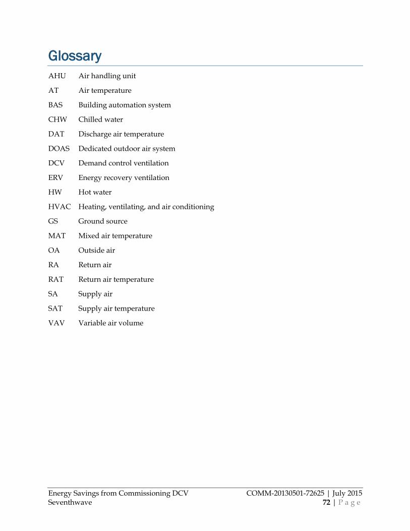
Energy Savings from Commissioning DCV COMM-20130501-72625 | July 2015 Seventhwave 72 | P a g e
Glossary AHU Air handling unit
AT Air temperature
BAS Building automation system
CHW Chilled water
DAT Discharge air temperature
DOAS Dedicated outdoor air system
DCV Demand control ventilation
ERV Energy recovery ventilation
HW Hot water
HVAC Heating, ventilating, and air conditioning
GS Ground source
MAT Mixed air temperature
OA Outside air
RA Return air
RAT Return air temperature
SA Supply air
SAT Supply air temperature
VAV Variable air volume
Energy Savings from Commissioning DCV COMM-20130501-72625 | July 2015 Seventhwave 73 | P a g e
References Acker 2009. Acker, B., Van Den Wymelenberg, K. Measurement and Verification of Demand Control Ventilation; Technical Report 20090205-03. Integrated Design Lab, University of Idaho, Boise, ID.
AEC 2003. Architectural Energy Corporation, Purdue University, and NIST. Final Report Compilation for Demand-Controlled Ventilation Assessment. California Energy Commission.
ASHRAE 2010. 62.1 User’s Manual ANSI/ASHRAE Standard 62.1.
Brandemuehl 1999. Brandemuehl, M., and J. Braun. The Impact of Demand Controlled and Economizer Ventilation Strategies on Energy Use in Buildings. ASHRAE Transactions 105 (2): 39-50.
DOE 2012. Code Notes 2012 IECC Demand Control Ventilation. U.S. Department of Energy, Energy Efficiency & Renewable Energy Building Technologies Program.
Dougan 2004. Dougan, D. and L. Damiano. CO2-Based Demand Control Ventilation: Do Risks Outweigh Potential Rewards. ASHRAE Journal, October 2004.
EDR 2007. Design Brief: Demand-controlled Ventilation. Energy Design Resources. http://energydesignresources.com/
Elovitz 1995. Minimum Outside Air Control Methods for VAV Systems. AHSRAE Transactions 101 (2): 613-618.
Emmerich 2001. Emmerich, S., and A. Persily. State-of-the-Art Review of CO2 Demand Controlled Ventilation Technology and Application. National Institute of Standards and Technology.
Fan 2014. Fan, Y., K. Kameishi, S. Onishi, K. Ito. Field-based Study on the Energy-saving Effects of CO2 Demand Controlled Ventilation in an Office with Application of Energy Recovery Ventilators. Energy and Buildings, 68 (A): 412-422.
Fisk 2009. Fisk, W. and T. Hong. Assessment of Energy Savings Potential from the Use of Demand Control Ventilation Systems in General Office Spaces in California. California Energy Commission Public Interest Energy Research Program.
Fisk 2009a. Fisk, W., D. Sullivan, S. Cohen and H. Han. Measuring Outdoor Air Intake Rates into Existing Buildings. Lawrence Berkeley National Laboratory.
Gabel 1986. Gabel, S., J. Janssen, J. Christoffel, and S. Scarborough. Carbon Dioxide-Based Ventilation Control System Demonstration. U. S. Department of Energy, DE-AC79-84BP15102.
Haghighat 1992. Haghighat, F. and G. Donnini. IAQ and Energy Management by Demand Controlled Ventilation. Environmental Technology 13: 351-359.
Lau 2013. Lau, J., X. Lin, G. Yuill. CO2-based DCV for Multiple Zone HVAC Systems. ASHRAE Research Project Report 1547-RP.
Energy Savings from Commissioning DCV COMM-20130501-72625 | July 2015 Seventhwave 74 | P a g e
LBL 2015. Carbon Dioxide Measurement & People Counting for Demand Controlled Ventilation. http://www.demandcontrolledventilation.lbl.gov/measure.html (accessed March 27, 2015).
Maripuu 2011. Demand controlled ventilation for better IAQ and Energy Efficiency. REHVA Journal, March 2011.
Nassif 2011. CO2-Based DCV Control Strategies for Multi-zone HVAC Systems. Proceedings of the Eleventh International Conference Enhanced Building Operations, New York City, October 18-20, 2011.
NIST 1995. Life-Cycle Costing Manual for the Federal Energy Management Program, NIST Handbook 135. US Department of Commerce National Institute of Standards and Technology, Prepared for the US Department of Energy.
Potter 1994. Potter, I., W. Booth. CO2 Controlled Mechanical Ventilated Systems. Technical Note. Bracknell, Berkshire: Building Services Research and Information Association, TN.
Schell 2001. Schell, M. and D. Inthout. Demand Control Ventilation Using CO2. ASHRAE Journal, February 2001.
Schulte 2005. Schulte, R., B. Bridges, and D. Grimsrud. Energy and Indoor Air Quality in Schools. NARUC Winter Meetings, Energy Resources and the Environment Committee. Washington, D.C.
Shrestha 2009. Strestha, S., and G. Maxwell. Product Testing Report: Wall Mounted Carbon Dioxide Transmitters. National Building Controls Information Program.
Taylor 2014. Demand Control Ventilation for multiple zone VAV systems — Problem Solved. ASHRAE Annual Conference, Seattle, WA, July 2014.
Trane 2005. Murphy, J. CO2-Based Demand-Controlled Ventilation with ASHRAE Standard 62.1-2004. Engineers Newsletter, 34:5.

Energy Savings from Commissioning DCV COMM-20130501-72625 | July 2015 Seventhwave 75 | P a g e
Appendix A: Monitoring Installation Checklist
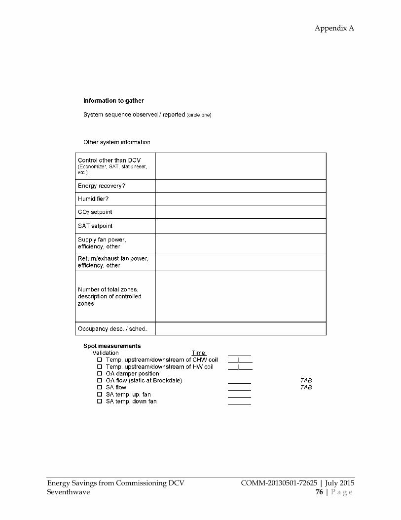
Appendix A
Energy Savings from Commissioning DCV COMM-20130501-72625 | July 2015 Seventhwave 76 | P a g e
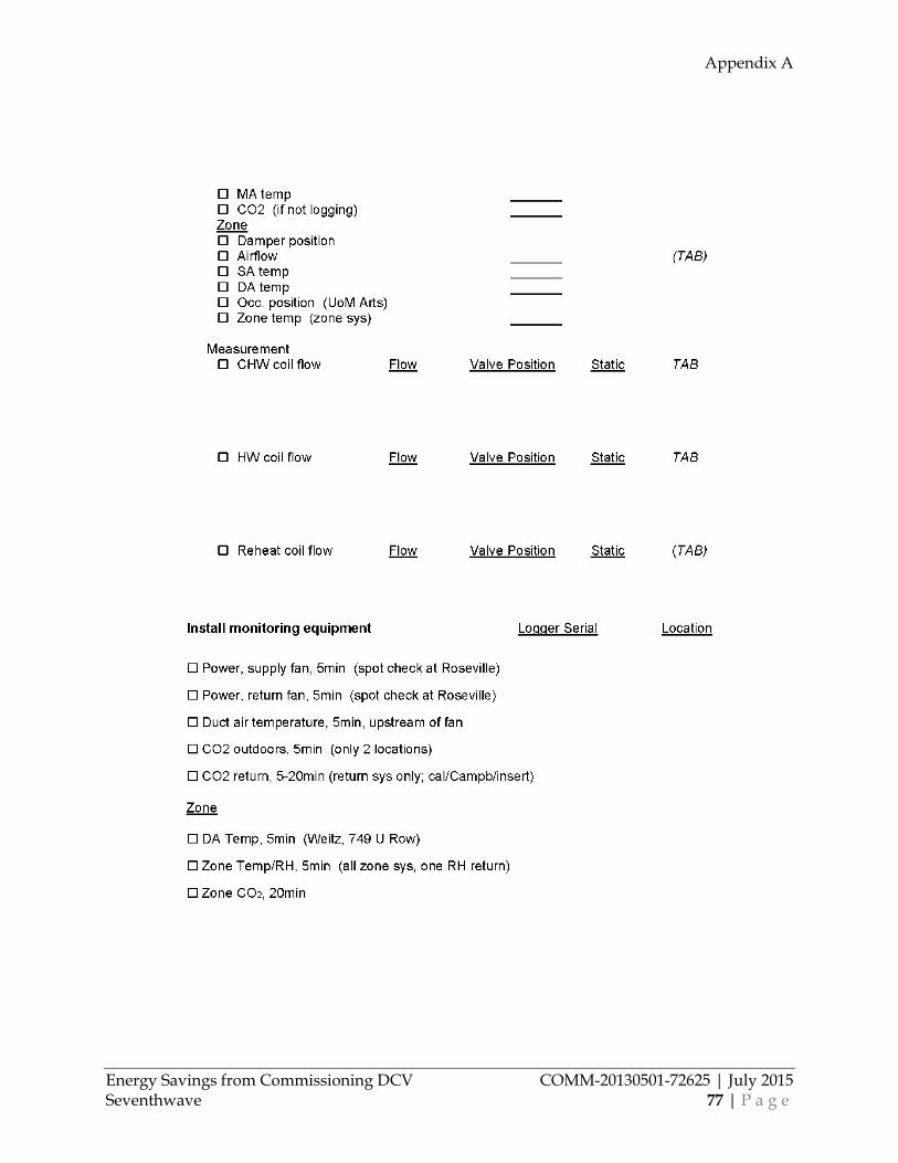
Appendix A
Energy Savings from Commissioning DCV COMM-20130501-72625 | July 2015 Seventhwave 77 | P a g e
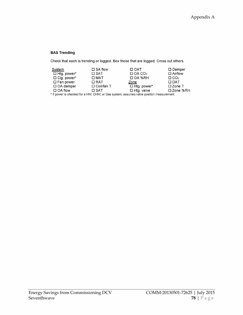
Appendix A
Energy Savings from Commissioning DCV COMM-20130501-72625 | July 2015 Seventhwave 78 | P a g e

Energy Savings from Commissioning DCV COMM-20130501-72625 | July 2015 Seventhwave 79 | P a g e
Appendix B: Occupant Satisfaction Survey
Energy Savings from Commissioning DCV COMM-20130501-72625 | July 2015 Seventhwave 80 | P a g e
Appendix C: Recommissioning Checklist General CO2 DCV Recommissioning Checklist The following document is a general checklist for recommissioning of CO2-based demand control ventilation. It could also be used for those phases of new-system commissioning that occur after basic functional testing. The items included represent everything that could be checked in a thorough process. Some steps may be removed – and should be for efficiency’s sake – where they are not necessary. Where deficiencies are uncovered, the specific action steps for resolution will depend heavily on the desired control sequence, and engineering judgement will be required. The process is designed for typical VAV systems; most of the steps would still apply to single zone or constant volume systems.
Obtain as many of the following as possible prior to beginning this process: Remote access to the BAS (if available) Mechanical and controls drawings As-built control logic with explanation of DCV sequence (if logic is not available or
understood, hints are provided below for determining the sequence) Trend list for BAS
o All relevant temperatures, airflow measurements, damper positions, and CO2 outputs should be trended for at least a week; several months is ideal for multi-season review. Any zones with CO2 sensors should have VAV flow/damper trended.
Assistance arranged from balancing agent for validating airflow measurement (optional)
1. Conduct system performance checks virtually (prior to visit) If at all possible, commissioning of DCV can be made both easier and much more effective if the BAS can be viewed remotely prior to the rest of this process. If trends allow, data should be reviewed for multiple seasons (at the very least the cooling season and some portion of economizer operation is useful). Note: OA damper position can be substituted for OA rate below where OA flow rate is not measured.
Check if DCV sequence is enabled and performing as expected: o Best to check this during hot weather when the economizer is off o Determine that the OA modulates roughly according to occupancy o When OA remains constant, determine if it is following the 1) lower limit or 2)
upper limit for flow as set by the sequence. Neither lower or upper limit necessarily reflect the design OA rate; they are simply limits set within the DCV sequence. OA should only remain constant for long periods at one of these two limits, and not some intermediate step (see Figure 19 in the report).
o Watch 1) OA damper position and 2) OA flow measurement (if available); determine which is being controlled to. Ideally, if OA flow measurement is available, DCV should be controlled to this measurement rather than damper position.
If OA flow measurement exists, verify upper limit of DCV vs. both design, then vs. current code for the current space use type. Consider that code may have been updated since original design, and the use type of the space may have changed since original design. The upper limit of the DCV sequence should only exceed code-required ventilation rates if CO2 setpoint is exceed for a significant period of time.
Look for ‘rogue’ DCV zones: zones that are just a fraction of the total OA flow, but seem to have high relatively high CO2 concentration the majority of the time (if found,

Appendix C
Energy Savings from Commissioning DCV COMM-20130501-72625 | July 2015 Seventhwave 81 | P a g e
consider increasing flow rate at that zone, or have sequence first open that VAV box prior to OA modulation at the AHU)
Check CO2 sensor readings at the end of unoccupied periods; they should return roughly to ambient 350-400 ppm levels. If they remain well above this level, either the CO2 sensors have drifted, or the building is not adequately ventilated.
Determine (or verify) the OA damper schedule. Note that damper schedule does not have to be identical to thermostat schedule, and could be left closed in the morning until substantial occupancy begins.
Verify proper economizer operation by reviewing OA flow rate during a day with moderate (40-70oF) temperatures; consider whether these temperatures might occur just in the morning (cooler) or late afternoon (warmer) during the observation period.
Determine (or verify) SAT setpoint and sequence by observing the relationship between SAT and OAT
Review position and selection of airflow measurement stations and compare with manufacturer’s requirements (check with the mfr.) and best practices. For more information see the report An Evaluation of Technologies for Real-Time Measurement of Rates of Outdoor Airflow into HVAC Systems ( https://escholarship.org/uc/item/22g9r57f)
2. Gather equipment needed for site visit: Thumb drive for data download and screenshots from BAS Camera Mechanical and controls drawings Handheld CO2 sensor CO2 test gas (0 or 1000 ppm) Ziploc bag for validating sensors that have no test port Flashlight Thermoanemometer (optional; only for advanced analysis) Installation and operation manuals for any AFMSs and CO2 sensors This checklist
3. Meet the system operator on-site and discuss system operation Review goals for the recommissioning process What is the occupancy schedule of the building, including both absolute
occupied/unoccupied times for HVAC (which are generally set for temperature control), but also understand the schedule of the ‘majority’ of occupants. Note that in some cases OA damper operation can be adjusted based on the latter (for example, in a library where two librarians come in at 6am to get the building ready, but the building doesn’t open until 9am, the OA damper can be scheduled to begin operating at 9am).
What is the design intent for the DCV sequence (if the operator is aware)? o Which sequence type is it? (see Table 4 in the report) o What are the upper and lower limits of OA flow control? o What is the CO2 setpoint? Is that based on anything specific? o Is airflow measurement used, or simply damper position?
Which sensors are used in DCV and can you locate them? Are other VAV controls currently in operation, such as SAT reset or economizer? How much have the staff adjusted the systems since it was designed (or last
commissioned)?
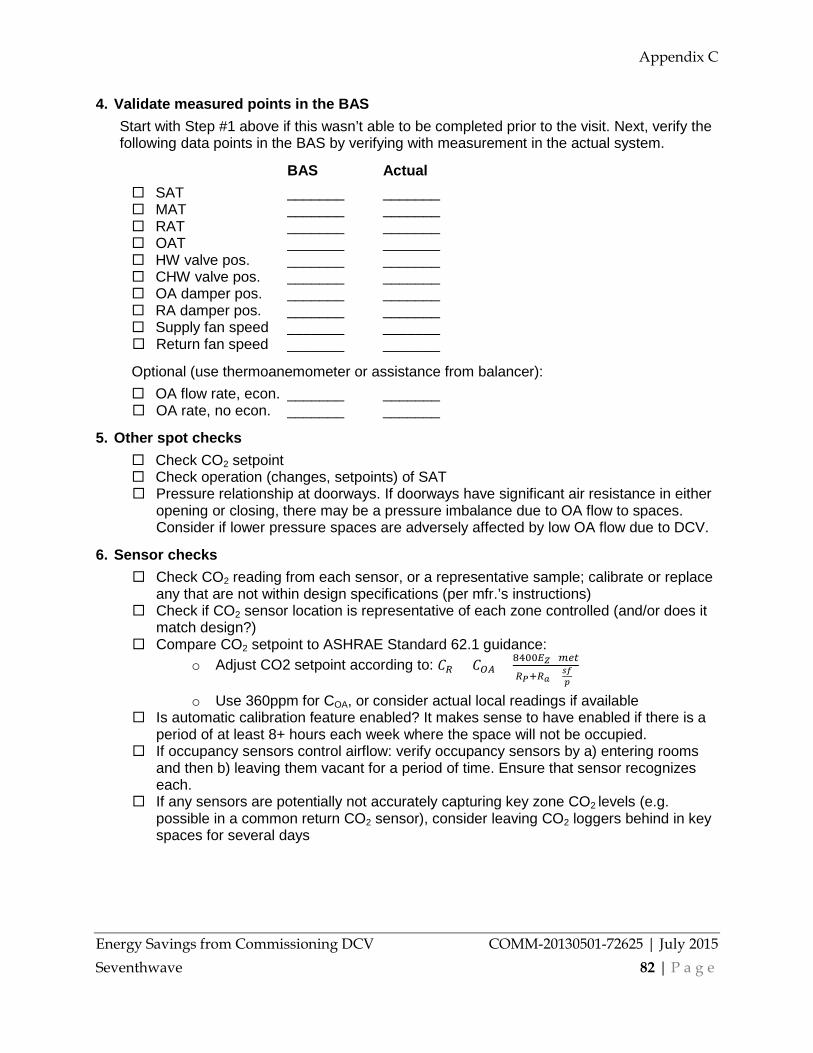
Appendix C
Energy Savings from Commissioning DCV COMM-20130501-72625 | July 2015 Seventhwave 82 | P a g e
4. Validate measured points in the BAS Start with Step #1 above if this wasn’t able to be completed prior to the visit. Next, verify the following data points in the BAS by verifying with measurement in the actual system.
BAS Actual SAT _______ _______ MAT _______ _______ RAT _______ _______ OAT _______ _______ HW valve pos. _______ _______ CHW valve pos. _______ _______ OA damper pos. _______ _______ RA damper pos. _______ _______ Supply fan speed _______ _______ Return fan speed _______ _______
Optional (use thermoanemometer or assistance from balancer): OA flow rate, econ. _______ _______ OA rate, no econ. _______ _______
5. Other spot checks Check CO2 setpoint Check operation (changes, setpoints) of SAT Pressure relationship at doorways. If doorways have significant air resistance in either
opening or closing, there may be a pressure imbalance due to OA flow to spaces. Consider if lower pressure spaces are adversely affected by low OA flow due to DCV.
6. Sensor checks Check CO2 reading from each sensor, or a representative sample; calibrate or replace
any that are not within design specifications (per mfr.’s instructions) Check if CO2 sensor location is representative of each zone controlled (and/or does it
match design?) Compare CO2 setpoint to ASHRAE Standard 62.1 guidance:
o Adjust CO2 setpoint according to: 𝐶𝐶𝑅𝑅 = 𝐶𝐶𝑂𝑂𝐴𝐴 + 8400𝐸𝐸𝑍𝑍×𝑠𝑠𝑅𝑅𝑜𝑜
𝑅𝑅𝑃𝑃+𝑅𝑅𝑎𝑎×(𝑠𝑠𝑠𝑠𝑝𝑝 )
o Use 360ppm for COA, or consider actual local readings if available Is automatic calibration feature enabled? It makes sense to have enabled if there is a
period of at least 8+ hours each week where the space will not be occupied. If occupancy sensors control airflow: verify occupancy sensors by a) entering rooms
and then b) leaving them vacant for a period of time. Ensure that sensor recognizes each.
If any sensors are potentially not accurately capturing key zone CO2 levels (e.g. possible in a common return CO2 sensor), consider leaving CO2 loggers behind in key spaces for several days
Appendix C
Energy Savings from Commissioning DCV COMM-20130501-72625 | July 2015 Seventhwave 83 | P a g e
7. Airflow measurement checks If AFMSs exist: Check that AFMS is installed according to manufacturer recommendations Verify that control uses the OA AFMS rather than OA damper position. If damper
position is used, and AFMS is installed properly, change sequence to use OA flow. Optional: verify AFMS accuracy based on balancer measurements.
8. System Performance Testing Once all previous checks are made, modify the sequence based on any deficiencies identified in those checks. Then, conduct system performance tests below. If time allows, run tests at two different fan speeds (as high and as low as possible without causing system problems or discomfort in any occupied spaces). If BAS access does not allow for false CO2 readings to be used, consider applying test gas to the CO2 sensor (to create a false low or high reading) or breathing directly on the sensor (to create a false high reading). Test the AHU: Modify CO2 reading via the BAS and determine system response; test
for CO2 levels both 1) below and 2) above setpoint. Allow the system to reach a steady state, and potentially determine the lower and upper limits for OA flow. For a more detailed test procedure see Functional Testing Guidance for DCV (https://view.officeapps.live.com/op/view.aspx?src=http%3A%2F%2Fwww.ftguide.org%2Fftg%2FTest_guidance%2FTests%2FTG13-Demand_Controlled_Ventilation.doc) on the Functional Testing and Design Guides website (http://www.ftguide.org/index.htm)
Test individual VAVs controlled by CO2: Modify CO2 reading via the BAS and determine zone response; test for CO2 levels both 1) below and 2) above setpoint. For a more detailed test procedure see Functional Testing Guidance for DCV.
Test OA damper: Visually verify the OA damper at at least two positions (watch travel), including fully closed.
o Also check for substantial air leakage at fully closed position. o Optional: check if OA position is proportional to OA flow measurement, or
%OA based on OAT, MAT, and RAT. Test occ. sensor impact: Force occupancy sensor to both occupied and unoccupied
mode, and test the effect on the system. Compare system responses to the design or intended sequence, and correct any deficiencies.
Appendix C
Energy Savings from Commissioning DCV COMM-20130501-72625 | July 2015 Seventhwave 84 | P a g e
9. Sequence Optimization In addition to correcting the deficiencies found above, consider improving system performance by optimizing the following parameters: Modify the system’s OA lower limit to a reasonably low value (consider Ra in ASHRAE
Standard 62.1) Modify the system’s OA upper limit so it doesn’t reach 100% based on CO2 alone
(both energy, comfort, and equipment freeze concerns could result from 100% OA depending on weather)
Consider if design OA rate can be changed based on changes in 1) code, 2) space use type, 3) desired safety factor since installation. Note that changing the design OA could lead to a direct change in OA lower and upper limits as well.
Consider the DCV sequence further as its now understood, and whether there is potentially more energy to be saved, or IAQ to be improved, from optimizing additional components (recognizing that each sequence may be a little different)
10. Closeout Make sure that all systems have been returned to normal operation following the
system performance tests. Report any deficiencies corrected or changes made back to the operator. Document what the current sequence is, how this can be viewed on the BAS, and
what the intended benefits of the sequence are. Explain to the operator. Create a brief plan for the operator to continue monitoring the system going forward
(see the Operation (and occupant behavior) section in the report)

Energy Savings from Commissioning DCV COMM-20130501-72625 | July 2015 Seventhwave 85 | P a g e
Appendix D: Building Characterization Data Table
This appendix covering the next three pages describes the characteristics of the 32 systems that we observed in our initial characterization. The first six systems in the list were those which we measured in detail.
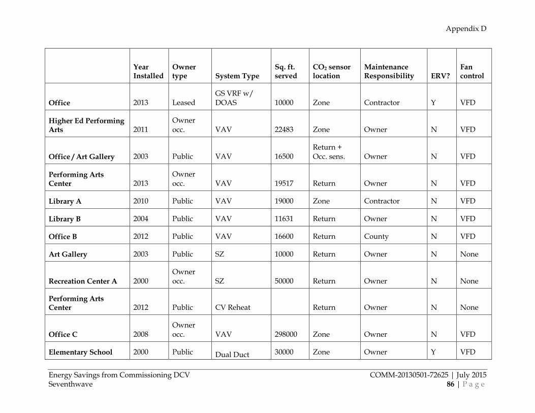
Appendix D
Energy Savings from Commissioning DCV COMM-20130501-72625 | July 2015 Seventhwave 86 | P a g e
Year Installed
Owner type System Type
Sq. ft. served
CO2 sensor location
Maintenance Responsibility ERV?
Fan control
Office 2013 Leased GS VRF w/ DOAS 10000 Zone Contractor Y VFD
Higher Ed Performing Arts 2011
Owner occ. VAV 22483 Zone Owner N VFD
Office / Art Gallery 2003 Public VAV 16500 Return + Occ. sens. Owner N VFD
Performing Arts Center 2013
Owner occ. VAV 19517 Return Owner N VFD
Library A 2010 Public VAV 19000 Zone Contractor N VFD
Library B 2004 Public VAV 11631 Return Owner N VFD
Office B 2012 Public VAV 16600 Return County N VFD
Art Gallery 2003 Public SZ 10000 Return Owner N None
Recreation Center A 2000 Owner occ. SZ 50000 Return Owner N None
Performing Arts Center 2012 Public CV Reheat
Return Owner N None
Office C 2008 Owner occ. VAV 298000 Zone Owner N VFD
Elementary School 2000 Public Dual Duct 30000 Zone Owner Y VFD
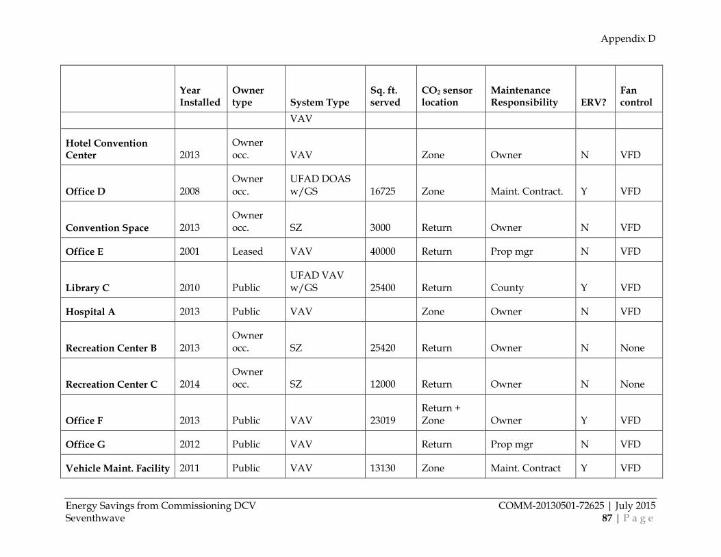
Appendix D
Energy Savings from Commissioning DCV COMM-20130501-72625 | July 2015 Seventhwave 87 | P a g e
Year Installed
Owner type System Type
Sq. ft. served
CO2 sensor location
Maintenance Responsibility ERV?
Fan control
VAV
Hotel Convention Center 2013
Owner occ. VAV Zone Owner N VFD
Office D 2008 Owner occ.
UFAD DOAS w/GS 16725 Zone Maint. Contract. Y VFD
Convention Space 2013 Owner occ. SZ 3000 Return Owner N VFD
Office E 2001 Leased VAV 40000 Return Prop mgr N VFD
Library C 2010 Public UFAD VAV w/GS 25400 Return County Y VFD
Hospital A 2013 Public VAV Zone Owner N VFD
Recreation Center B 2013 Owner occ. SZ 25420 Return Owner N None
Recreation Center C 2014 Owner occ. SZ 12000 Return Owner N None
Office F 2013 Public VAV 23019 Return + Zone Owner Y VFD
Office G 2012 Public VAV Return Prop mgr N VFD
Vehicle Maint. Facility 2011 Public VAV 13130 Zone Maint. Contract Y VFD
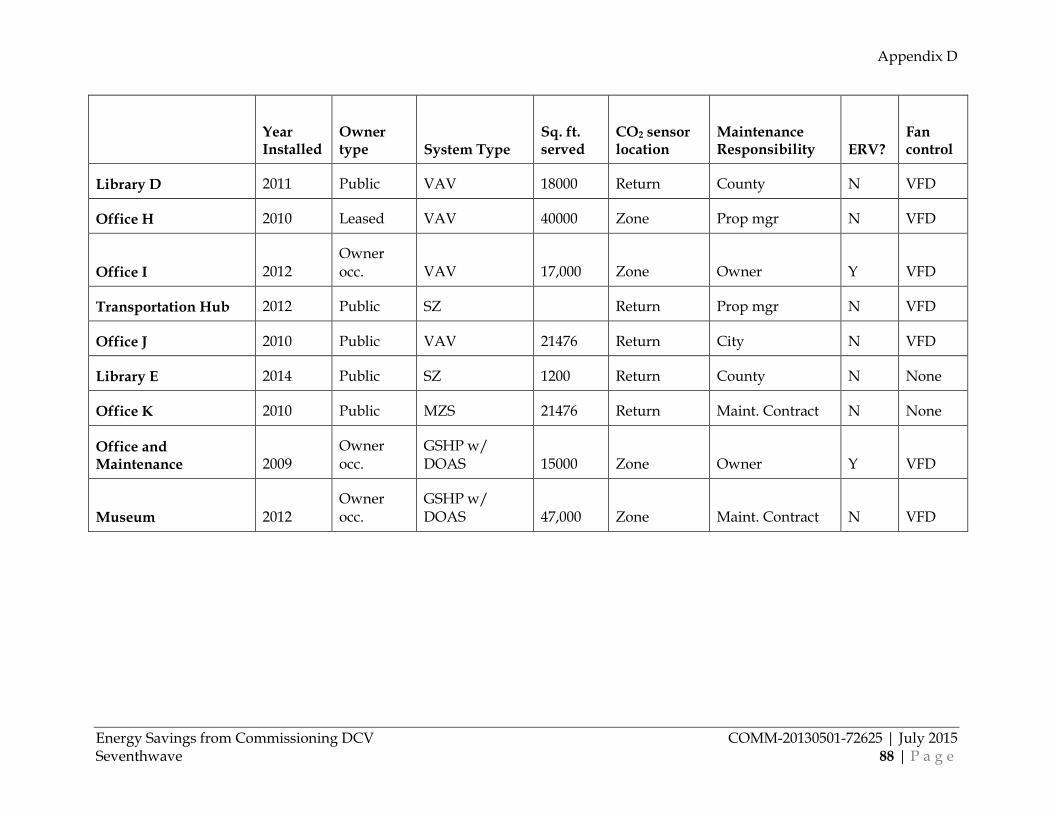
Appendix D
Energy Savings from Commissioning DCV COMM-20130501-72625 | July 2015 Seventhwave 88 | P a g e
Year Installed
Owner type System Type
Sq. ft. served
CO2 sensor location
Maintenance Responsibility ERV?
Fan control
Library D 2011 Public VAV 18000 Return County N VFD
Office H 2010 Leased VAV 40000 Zone Prop mgr N VFD
Office I 2012 Owner occ. VAV 17,000 Zone Owner Y VFD
Transportation Hub 2012 Public SZ Return Prop mgr N VFD
Office J 2010 Public VAV 21476 Return City N VFD
Library E 2014 Public SZ 1200 Return County N None
Office K 2010 Public MZS 21476 Return Maint. Contract N None
Office and Maintenance 2009
Owner occ.
GSHP w/ DOAS 15000 Zone Owner Y VFD
Museum 2012 Owner occ.
GSHP w/ DOAS 47,000 Zone Maint. Contract N VFD