energy efficient building services building design
TRANSCRIPT

Energy Efficient Building Services
61
Bui
ldin
gD
esig
n
The form and fabric performance of the building plays a vital role inthe achievement of in-use energy efficiency.
Optimum energy efficiency can be achieved by utilising the superiorlifetime thermal, low air leakage and insulation continuityperformance certainty of Kingspan’s roof and wall solutions,. Thisallows the design team to downsize HVAC plant, minimising energyusage and cost levels over the lifetime of the building.This also achieves lower Carbon Dioxide (CO2) emissions andmaximises environmental sustainability for future generations.
The key areas for consideration are:
Heating/Cooling System EfficiencyThe heating or cooling system of a building must be designed andinstalled to make efficient use of energy for the conservation of fueland power. (refer to Parts L2 and J)
Space Heating Controls(refer to Parts L2 and J)
Artificial Lighting(refer to Parts L2 and J)
Building ServicesTo achieve energy efficiency in practice and compliance withParts L2 and J, the building and it’s services systems should beappropriately designed and constructed. Information should alsobe provided such that the energy performance of the building inuse can be assessed.
When designing building services installations, provision should bemade to facilitate appropriate inspection and commissioning.
In large complex buildings, it may be sensible to consider theprovisions for the conservation of fuel and power separately for thedifferent zonal areas of the building in order to establish themeasures appropriate to each area.
Further detailed guidance on energy efficiency can be found in theCIBSE Guide of Energy Efficiency in Buildings.
Air Conditioning, Mechanical VentilationBuildings incorporating air conditioning or mechanical ventilationmust be designed and constructed so that:
a) the form and fabric of the building do not result in arequirement for excessive installed capacity of coolingequipment; and
b) fans, pumps, refrigeration equipment and other componentsare reasonably efficient and appropriately sized to have nomore capacity for demand and standby than is necessary; and
c) there are appropriate means of managing, controlling andmonitoring the operation of equipment and systems.
The requirements for energy efficiency of air conditioning andmechanical ventilation, will be met. (refer to Parts L2 and J)
Inspection and Commissioning of Building Services Systems* The building services installation must:
a) be capable of operating at the manufacturer’s specifiedefficiency; and
b) incorporate adequate provisions for testing and commissioningto be carried out satisfactorily.
* Written information must be provided for the building’soccupier on the installed building services plant and controlsrequired to comply with Part L2 and J, their method ofoperation, state of maintenance, and details forecastingannual energy consumption for the building.
The requirements as regards the commissioning of the buildingservices, will be met by certifying that commissioning of theinstallation has been done in accordance with CIBSECommissioning Codes and BSRIA Commissioning Guides.
The requirements as regards the provision of information forenergy efficient operation will be met by a self-contained buildinglog-book containing the following details:
a) a schedule of the floor areas of each of the building zonescategorised by environmental servicing type (e.g. air-conditioned, naturally ventilated); and
b) the purpose of the individual building services systems; and
c) the location of the relevant plant and equipment; and
d) the installed capacities (input power and output rating) of theservices plant; and
e) simple descriptions of the operational and control strategies ofthe energy consuming services in the building; and
f) operating and maintenance instructions that include provisionsenabling the specified performance to be sustained duringoccupation.
Note: Please refer to Parts L2 and J with regard to buildingservices compliance requirements.
For more information on Kingspan Insulated Panels visit www.barbourproductsearch.info

62
Building fabric insulation and airtightness certainty play a vital role in optimising energy efficiency, lowering energy usage and
reducing operating costs over the building’s lifetime.
Additionally, significant capital cost savings can be made by downsizing HVAC plant and services at new build stage.
Kingspan’s insulated roof and wall systems facilitate the construction of energy efficient and low Carbon Dioxide (CO2)
emission buildings, providing environmentally sustainable construction.
To achieve the optimum energy efficiency and minimum CarbonEmissions (CO2) levels contact Kingspan’s Technical DesignBureau for project specific HVAC plant, energy usage and CO2
emissions analysis on 01352 716101 Cheaper to Build - Cheaper to Operate
Earth’s Atmosphere0.03% of CO2 in the atmosphere. Average temperature: +15°C
For more information on Kingspan Insulated Panels visit www.barbourproductsearch.info

Case Study: Air Leakage for 10,000m2 Building Heated to 19°C
Kingspan Sustainable ConstructionPart L2 Lo-Air Leakage Lo-Carbon CO2 Lo-Energy
Air Leakage Air Leakage Saving Saving on Total Heating10m3/hr/m2 @ 50 Pa 5m3/hr/m2 @ 50 Pa CO2 Emissions Energy by Reduced Air Leakage
Location - Sheltered/UrbanEnergy to heat leaking airper annum 130,096 kWH 65,048 kWH 13,660 kg 65,048 kWH
Energy wasted as % totalenergy used to heat building 21.2% 11.9% 11.9% 10.6%
Location - Exposed/Scattered Wind BreaksEnergy to heat leaking airper annum 154,717 kWH 77,359 kWH 16,245 kg 77,359 kWH
Energy wasted as % totalenergy used to heat building 24.3% 13.8% 13.8% 12.1%
Energy Efficient Building Services
63
Bui
ldin
gD
esig
n
Energy Use in Heating a 5,000m2 BuildingEnergy
Area U-Value ConsumptionElement (m2) (W/m2K) (kWH/annum)Floor 5,000 0.25 70,710Roof 5,02610% Rooflights 500 2.20 62,225Roof Panels 4,526 0.25 64,007Walls 2,23110% Glazing & Doors 220 2.00 24,890Wall Panels 2,011 0.35 39,815Total 261,647
Case Study: Air Leakage for 5,000m2 Building Heated to 19°C
Kingspan Sustainable ConstructionPart L2 Lo-Air Leakage Lo-Carbon CO2 Lo-Energy
Air Leakage Air Leakage Saving Saving on Total Heating10m3/hr/m2 @ 50 Pa 5m3/hr/m2 @ 50 Pa CO2 Emissions Energy by Reduced Air Leakage
Location - Sheltered/UrbanEnergy to heat leaking airper annum 76,741 kWH 38,371 kWH 8,058 kg 38,371 kWH
Energy wasted as % totalenergy used to heat building 22.7% 12.8% 12.8% 11.4%
Location - Exposed/Scattered Wind BreaksEnergy to heat leaking airper annum 91,556 kWH 45,778 kWH 9,613 kg 45,778 kWH
Energy wasted as % totalenergy used to heat building 25.9% 14.9% 14.9% 13.0%
• Energy savings can be made by reducing the air leakage rate to 5m3/hr/m2 with the use of Kingspan’s insulated roof and wall systems, this also reduces Carbon emissions(CO2) and the Climate Change Levy (CCL) energy tax payable.
• Energy savings can be made by reducing the air leakage rate to 5m3/hr/m2 with the use of Kingspan’s insulated roof and wall systems, this also reduces Carbon emissions(CO2) and the Climate Change Levy (CCL) energy tax payable.
Energy Use in Heating a 10,000m2 Double Span BuildingEnergy
Area U-Value ConsumptionElement (m2) (W/m2K) (kWH/annum)Floor 10,000 0.25 141,420Roof 10,05210% Rooflights 1,000 2.20 124,450Roof Panels 9,052 0.25 128,013Walls 3,06210% Glazing & Doors 300 2.00 33,941Wall Panels 2,762 0.35 54,684Total 482,508
60m40m
6m
30m40m
6m
The following tables indicate energy and CO2 emission savings
For more information on Kingspan Insulated Panels visit www.barbourproductsearch.info

64
Gutter Types and Location
Gutter layout and roof drainage require careful consideration at thebuilding design stage to guarantee reliable performance.Eaves gutters are outside the building envelope and any failure orleakage would not normally mean water entering the building.Failure of valley, hip, parapet and boundary wall gutters which arean integral part of the roof results in water pouring into the buildingdamaging both the fabric of the building and its contents.Therefore, correct gutter design, construction and in use reliabilityform a vital part of the project team’s considerations.
The design details for roof drainage are based on therecommendations in BS EN 12056-3: 2000 Gravity drainagesystems inside buildings – Part 3: Roof drainage, layout andcalculation.
Kingspan design and manufacture a range of standard andcustomised internal and external gutter systems, see page 66.
Rainfall RateRainfall rates have been recorded throughout the country overmany years, and this information has been used in BS EN 12056-3 to indicate where and how frequently particular rainfall rates arelikely to occur.
A rate of 75mm/hr is suggested as a normal basis for calculation,though this is likely to be exceeded twice a year in some parts ofthe country (East Anglia) and less frequently elsewhere. This rate isgenerally suitable for eaves gutters.
Most gutter and drainage systems have to be able to deal withshort periods of excess rainfall, provided they are correctlydesigned and maintained. Higher rainfall rates such as 150mm/hrcan be used if required to reduce overflow risks further, e.g. forvalley, hip, parapet or boundary wall gutters.
Design - GeneralTo establish the correct gutter design and size it is necessary tocalculate the rainwater discharge rate from the roof. This involvesassessing the rainfall rate and the effective catchment area, Ae.
Roof Drainage
Roofs are constructed in a variety of shapes, from a simple pitched arrangement with external gutters, to a more complex
multispan construction with valley, hip, parapet or boundary wall gutters.
ParapetorBoundaryWall Gutter
ValleyGutter
ExternalGutter
Valley Gutter Boundary Wall Gutter Gutter
For more information on Kingspan Insulated Panels visit www.barbourproductsearch.info

Effective Catchment Area, AeThe water drainage from a roof includes rain falling directly ontothe roof and also wind driven rain running off adjacent roofs, wallsand parapets which has to be taken into account.
The total effective area therefore is:- the shaded roof plate area - the shaded vertical elevation area
Roof Drainage
65
Bui
ldin
gD
esig
n
A
20 10
Note: All dimensionsin linear metres
2
Example:The effective catchment area Ae for slope A is:
Roof Plate Elevation Wall
A = ((10 x 20) + (2 x 20) + (2 x 10))
= 225m2
2 4
The gutter and downpipe arrangement has to be designed toprovide sufficient capacity for the predicted discharge rate.
Gutter design is normally based on the following assumptions:
• Slope of the gutter is less than 1 in 350.
• The gutter has a uniform cross section.
• The outlets are large enough to ensure the gutter discharges freely.
• The dimension from a stop end to outlet should be less than50 x maximum water depth
• The dimension between outlets should be less than 100 x maximum water depth.
The depth of water in the gutter will vary from a maximum at theupstream end, to a minimum ‘critical depth’ at the outlet,depending on gutter shape. For rectangular section gutters themaximum water depth equals twice the depth at the outlet.
Valley, hip, parapet and boundary wall gutters should include anallowance for freeboard to allow for splashing and waves below thespill over level. BS EN 12056-3 recommends minimum freeboarddepth between 25mm and 0.3 x total gutter depth up to maximumof 75mm. A minimum 50mm freeboard is often considered goodpractice.
Kingspan Technical Design Bureau provide a gutter anddownpipe calculation service.
For more information on Kingspan Insulated Panels visit www.barbourproductsearch.info

Roof Drainage
66
Note: that for the same discharge rate, arrangement b only requires half the capacityof arrangement a. This shows that outlets at stop ends can be less efficient
Q
YcYu
Q2
Q2
Q
YcYu Yc Yu Yc Yc Yu
Q4
Q4
Q4
Q4
Gutter DesignEaves GuttersFlow capacities for individual shapes and lengths for gutters, outletsizes and downpipe arrangement can be calculated by designersor Kingspan’s Technical Design Bureau.
As eaves gutters are outside the building envelope the design is lesscritical than for a valley, hip, parapet or boundary wall gutter, for thisreason freeboard is not usually calculated in eaves gutter designs.
Valley, Hip, Parapet and Boundary Wall GuttersThese are effectively part of the roof construction and theconsequences of overflow or leakage are serious, so their correctdesign and installation are very important.
As they are part of the roof they must also be insulated to complywith Parts L2 and J with respect to avoiding excess heat loss,thermal bridging and the risk of condensation.
Kingspan manufacture a range of insulated gutters for which thePsi Value (Y) and condensation risk f-factor values have beencalculated as illustrated in the relevant product sections of thisguide. Gutters should be wide enough and sufficiently strong toallow foot traffic during installation and maintenance and complywith CDM Regulations.
Industry guides to good practice recommend minimum solewidths of 500mm for valleys, and 300mm for parapet andboundary wall gutters.
In general the shape of these gutters will be dictated by roof slope,design flow rate and the dimension between downpipes.An additional ‘freeboard’ over the maximum water level isrecommended to allow for splashing and waves (up to 75mm).
Gutters and outlets have to be dimensionally integrated into thebuilding’s structural/secondary steelwork.
Valley Gutter
Valley Hip Gutter
Eaves - Highline Gutter
Parapet Gutter
Boundary Wall Gutter
Typical Gutter & Downpipe AnalysisSingle Span (a)
Multispan (b)
Kingflow Insulated Gutter Range
For more information on Kingspan Insulated Panels visit www.barbourproductsearch.info

67
Bui
ldin
gD
esig
n
Roof Drainage
Tapered Outlet
Overflow Weirs
Box Outlet
150 x 350 long
3514
015
015
014
0
150 dia.
150 dia.
180 wide x 1015 long
(Typical dimensions in mm)
(Typical dimensions in mm)
PurlinInsul.to Gutter
Outlets & Overflow WeirsOutlets should be in the bottom of the gutter and they can eitherbe directly into a pipe, or preferably via a box to ensure optimumdrainage flow from the gutter.
BS EN 12056-3 defines how to determine the correct box andpipe sizes for a particular situation. Typically the diameter of adownpipe connected directly to the sole of a rectangular guttershould be approximately 75% of the width of the gutter.
Siphonic Rainwater SystemsWhere conventional gravity rainwater systems may causeobstructions inside a building because of reduced headroombelow pipes under the roofs and/or position of vertical pipes,siphonic systems should be considered. Siphonic pipes are usuallysmaller in diameter than normal rainwater pipes and the system isdriven by pressure differences which allows horizontal pipe runs tobe used.
Siphonic systems have to be designed by the manufacturer to suitthe roof layout with the collection area and outlet capacitybalanced against pressures in the pipe system. Each pipe systemhas a maximum flow rate and also a minimum limit at whichsiphonic self cleaning action will commence.
Excess water at one outlet needs to be able to flow along thegutter to other outlets which introduces limits on smaller gutters.The system needs to be designed so that the minimum velocity inthe system at the design rainfall shall prevent deposition in thepipework and ensure rapid commencement of the siphonic effect.
The large difference between average rainfall intensity and peakdesign rainfall calculated to BS EN 12056 in some parts of theBritish Isles often requires that two siphonic systems are fitted tovalley gutters. One is designed to accept the normal rainfall rangeand the secondary system (which can be siphonic or gravity) isnormally dry except in heavy storms.
Note: Overflow weirs should always be fitted to give warning of blocked outlets.
Conventional Rainwater Gravity Drainage Method
8 downpipes and internal undergrounddrainage incorporating inspection chambers
Self Priming Siphonic System
A typical siphonic outlet:The PrimaFlow® Self Priming Siphonic Outlet
Siphonic systems can be designed and supplied by:
Fullflow Te: 0114 247 3655Geberit UK Te: 01765 602082Sapaflow Te: 01226 297200
OverflowWeir
Siphonic
Gravity
Seal
Optional spitterwith weir
Stop-end
Straight outlet(round), weldedor loose
Tapered outlet,welded or loose
For more information on Kingspan Insulated Panels visit www.barbourproductsearch.info

Roof Drainage
68
Thermal InsulationInternal gutter systems have to thermally comply with Parts L2 andJ as they are classed as part of the roof construction. However,Kingspan recommend a U-value of 0.35W/m2K which providespre-melt drainage in the event of snow fall and ice formation.This facilitates drainage of the roof system under winterconditions. Additionally analysis of condensation risk f-factorand thermal bridge heat loss Psi Value (YY) is necessary. Thesevalues are then built into the Alpha value (aa) whole building heatloss calculation.
Insurer approved Loss Prevention Certification Board(LPCB) or Factory Mutual (FM) insulation board should beincorporated to prevent risk of fire development, propagation orspread.
DurabilityAll gutters are subjected to severe corrosive conditions due tofrequency of wetting, accumulation of debris and dirt, which canretain water and moisture for extended periods. Internal gutters areused as walkways during and after construction and are subject toperiodic cleaning, therefore, any protective coating systems have tobe resistant to damage.
Gutter replacement is disruptive and expensive as it involvesstripping out elements and possible replacement of the roofsystem.
Therefore, overall lifetime durability for internal gutters shouldbe 30 years, this includes periodic maintenance.
Protective CoatingsExternal gutters - Galvanised substrate - S220GD + ZA to
BS EN 10214:1992- internal coating 200 micron Plastisol.
Internal gutters - Galvanised substrate - Fe P02G Z600 to BS EN10143:1993
- single ply membrane- internal coating 200 micron Plastisol.
Site InstallationSite installation of gutter systems is a high risk activity whichrequires specific Health & Safety and CDM procedures andmethod statements.
MaintenanceIt is important to recognise that the performance of all guttersystems will deteriorate in time because of leaves, silt and otherdebris. The system should be designed with appropriate safetyfactors to allow for this, depending on risk of accumulation andfrequency of maintenance. BS 5427 recommends regularscheduled inspections which should be at least once per year inmost locations.
For more information on Kingspan Insulated Panels visit www.barbourproductsearch.info

Kingspan Gutter Design Form
69
Bui
ldin
gD
esig
n
To obtain Kingspan design recommendations in accordance with the method of BS EN 12056-3: 2000 please complete the following formand Email or fax it to the Technical Design Bureau.
Email: [email protected] or Fax: 01352 716111
From Name
Company
Telephone
Fax
Please complete one page for each type of gutter, ticking the appropriate box and giving full details to all questions.
Project Details
Location of projecte.g. Town
Kingspan roof system KS1000 RW KS1000 TS KS1000 LP - CR KS500/1000 ZIP
KS1000 RT KS1000 SF
Gutter type Highline Eaves Valley Hip Parapet Boundary Wall(not insulated)
U-value for gutter 0.35 W/m2K (for pre-melt design) 0.25 W/m2K
Roof pitch Slope 1 m Slope 2 m
Roof slope length Slope 1 m Slope 2 m
Roof length Slope 1 m Slope 2 m
Gutter length m
Area of any other roofs draining onto proposed roof m2
Area of any wall catchment/parapet draining onto proposed roof m2
Purlin depth mm
Any other relevant information
For more information on Kingspan Insulated Panels visit www.barbourproductsearch.info

70
Superior thermal performanceand air tightness built-in“ ”
Superior build quality Thermography image showing 100% thermalperformance
Air pressurisation testing
For more information on Kingspan Insulated Panels visit www.barbourproductsearch.info

Build Quality, Post Construction Testing& Handover
71
Bui
ldin
gD
esig
n
Project Team – Competent Person(s)Part L2: 2002 of Building Regulations (England and Wales)introduced site testing of the building envelope to confirmcompliance with the design for thermal insulation and air leakage.Where infra-red thermography and/or air leakage testing are to becarried out on completion of the building it will be expensive torectify any defects found, it is therefore essential that the wholeproject team, of designer, main contractor and sub-contractorswork together to achieve full Part L2 compliance at the design andconstruction stages and therefore, meet the project's energyefficiency and Carbon Dioxide (CO2) emission targets.
During design, tendering and building control applications it islikely that the architect, designer or independent specialists will bethe competent person(s) for achieving compliance with thermalinsulation and air leakage requirements of Part L2.
Specialists may be required especially on larger complex projectsto provide independent advice as design, construction methodsand material specifications evolve.
When work starts on-site the developer/main contractor willassume responsibility for compliance and may need the servicesof specialist competent person(s) to ensure that any design,material changes and workmanship quality are fully compliant.
Kingspan’s robust standard details (RSD’s) have been developedto be installer friendly so that a high level of workmanship qualitycan be achieved combined with fast installation speed.
Design Specification & Build QualityComplianceThe materials to be installed and workmanship quality has to beinspected during construction to enable the competent person(s)to provide the required certificate or declaration following airpressurisation testing and thermographic inspection survey.
Kingspan’s construction details have been designed to provide the quoted thermal insulation (U-value), minimal condensation risk (f-factor) and thermal bridge heat loss (Psi value (Y)) values aseasily as possible under site conditions.
Thermographic InspectionPart L2 requires that responsibility for achieving compliance toavoid excessive thermal bridging, rests with the person(s) carryingout the work. The person(s) responsible for achieving complianceshould (if suitably qualified) provide a certificate or declaration thatthe provisions meet the requirement of Part L2, alternatively acompetent person(s) may issue such a declaration.
Alternatively a thermographic inspection survey by competentperson(s) should be carried to demonstrate that the insulation isreasonably continuous over the visible envelope of the buildingand that excessive thermal bridging is avoided.
Note: Building Control should be asked to confirm in advance who theyconsider is competent to complete the various declarations required beforethe completion certificate is issued.
Failure to achieve regulatory compliance will result in project
handover delays, rectification costs and consequential losses.
Thermographic Inspection Survey SpecificationSee page 72 for thermographic inspection specification documentwhich can be incorporated into project tender and contractdocuments.
Air Permeability TestingOn buildings of any size, an air leakage test has to be carried outto provide a declaration from a competent person(s) that the testresult demonstrates regulatory compliance either to Part L1 or L2as appropriate.
Alternatively for buildings of less than 1000m2 floor area adeclaration that appropriate design and installation has beencarried out to achieve conformity to specification for regulatorycompliance.
Kingspan’s construction solutions and details have been designedto provide a barrier to air leakage which competent claddingcontractors can be expected to install successfully on site.
Note: There is no requirement in Part J Building Standards Scotland for eitherair leakage testing or thermographic inspection.
Air Pressurisation Testing SpecificationSee page 72 for air pressurisation testing specification documentwhich can be incorporated into project tender and contractdocuments.
Project Specification & MaintenanceManualCompliance with CDM Regulations will require that details of thecladding specification and maintenance recommendations areincluded in the Operation and Maintenance Manuals for thecompleted building. Part L2 recommends that the measured airpermeability of the building is included in the building log-book,together with references to the O & M Manual.
Energy Usage Log BookPart L2 requires that a log book be provided giving details of theinstalled building services plant and controls, their method ofoperation and maintenance, and other details that collectivelyenable energy consumption to be monitored and controlled. Thethermal insulation values and airtightness of the building envelopeare significant contributors to the overall energy efficiencyperformance of the building, therefore, these details should beincluded in the log book.
For more information on Kingspan Insulated Panels visit www.barbourproductsearch.info

Build Quality, Post Construction Testing& Handover
Thermographic Survey Specification1. Thermographic SurveysCarry out infra-red thermography inspections using a specialistconsultant to demonstrate that the insulation of the building isreasonably continuous over the whole visible envelope, that thereare no unintentional air leakage paths through the fabric and thatinsulation aspects of the works have been carried out inaccordance with construction drawings.
2. Survey MethodSurvey to be carried out as recommended in BS EN 13187 andCIBSE Technical Memoranda TM23:2000 Testing Buildings for AirLeakage.
3. ProgrammeThe contractor should allow sufficient time in the programme torectify any defects that become apparent in testing and retestingto demonstrate compliance prior to the completion date.
4. Quality Control and SupervisionThe contractor shall be responsible for the site quality control tocheck that the sub-contractors and suppliers complete the works inaccordance with the contract drawings and specifications –including any approved subcontractor’s drawings where applicable.
5. AccessThe contractor should provide appropriate access agreed inadvance with the specialist.
6. Conditions and TestingThe contractor should ensure that the test is carried out underappropriate conditions:
• The contractor should allow for heating the building toestablish a temperature difference between inside and outsideof at least 10ºC during the test and at least 5ºC for thepreceding 24 hours
• All building surfaces to be inspected to be dry
• No precipitation (including mist and fog) immediately prior orduring the survey
• Wind speeds during the survey must not exceed 10 m/s
7. WitnessingTests to witnessed by the contractor, the Contract Administrator(CA) and Building Inspector (if required). The contractor shouldliaise with all parties in advance to ensure their attendance.
8. Test Failure and Re-testingShould the tests reveal defects in detailing or in the continuity orinsulation or the contractor shall be responsible for undertaking thenecessary investigation, allowing for inspection by the CA,remedial sealing works and further tests at his own cost until it canbe demonstrated that the building complies with Clause 1.
9. Report and CertificateProvide a report illustrated with thermal images of any defects(including temperature calibration scale) of the results of the surveyto the CA, Building Control, the employer and Planning Supervisorfor inclusion in the Health and Safety File.
Airtightness Testing Specification1. IntroductionThe contractor should note that the building is to be constructedso that air infiltration and exfiltration through the external envelopeis minimised. It has been detailed accordingly and the contractorshould pay particular attention to this aspect during tendering,procurement, construction, commissioning and handover.
2. Air Permeability StandardThe building will be tested for air tightness before practicalcompletion and must achieve the following minimum standard ofair permeability to Part L2* of the Building Regulations for Englandand Wales:
• Not greater than 10m3/hr/m2 * of building envelope at amaintained pressure difference of 50Pa.
*or clients specification.
3. Contractor’s DesignAchieving a high standard of air permeability dependsfundamentally on standards of workmanship on site and,therefore, responsibility for achieving this standard rests with theContractor.
4. Specialist InputIn order to achieve the above, the Contractor may wish to employa specialist to provide a service that includes the following:
Design Review in advance of procurement:
a) Comment in writing on the construction information preparedby the design team, identifying potential gaps or weaknesses inthe detailing of the air barrier or potential buildability issues.
b) Confirm those parts of the building which will be consideredoutside the building envelope during testing.
c) Submit as mark-ups or in writing alternative proposals ormodifications to design team information to enhance airtightness or improve buildability, provided always that theyfollow the design intent of the design team’s drawings.
d) Identify further details required from the design team in order toclarify continuity of the air barrier.
e) Advise the contractor on subcontract responsibility andsequencing to ensure completeness and continuity of the airbarrier.
Construction phase:
a) Visit site at suitable times throughout construction to advise onproposed construction stages in advance, bringing particularwatch points to the attention of the contractor’s andsubcontractors’ staff.
72
For more information on Kingspan Insulated Panels visit www.barbourproductsearch.info

Build Quality, Post Construction Testing& Handover
73
Bui
ldin
gD
esig
n
Contractor’s Duties6.1 Integrity, Continuity and Durability of theAir Barrier SystemThe contractor is responsible for the integrity, continuity anddurability of the air barrier system which must be addressed by allrelevant components and at all relevant junctions, penetrations oropenings.
6.2 Coordination and Allocation of ResponsibilityThe contractor shall be responsible for coordinating the works toachieve the specified air tightness performance and for specifyingwhich subcontractor or supplier of each part of the building isresponsible for the air tightness of the junction between their workand another’s.
6.3 Performance of ComponentsThe contractor shall be responsible for ensuring that each supplierof each part of the building is responsible for achieving the airinfiltration performance of that part of the work.
6.4 Quality Control and SupervisionThe contractor shall be responsible for the site quality control tocheck that the sub-contractors and suppliers will achieve the airtightness performance requirements.
6.5 ProgrammeThe contractor should allow sufficient time in the programme torectify any defects that become apparent in testing and retestingto demonstrate compliance prior to the completion date.
6.6 Approval of VariationsAll sealing works required to ensure continuity of the air barriersystem must be carried out in accordance with the design detailsand with materials approved by the employer’s representative.Any variation to the works involving air barrier continuity must beapproved by the employer’s representative.
6.7 Preparatory Work and Temporary Sealing for TestingAllow for preparatory works and temporary sealing (and removalon completion) of free openings, flues, air supply openings andventilation system inlets and outlets as described in CIBSETechnical Memorandum TM23 – Testing Buildings for Air Leakage.
6.8 Partial Handover/Phased ConstructionCarry out additional testing to suit phased construction orhandover. Allow for temporary sealing/ enhancement as requiredfor partial testing, for example, in connection with partial handover,noting that materials and detailing specified for internal walls mayrequire enhancement in order to provide an air tight barrier forsuch testing.
6.9 Test Failure and Re-testingShould the building fail to comply with the specified maximum airleakage, the contractor shall be responsible for undertaking thenecessary air leakage identification, remedial sealing works andfurther fan pressurisation tests at their own cost until thespecification is achieved and demonstrated to the employer’srepresentative.
b) Visit site to inspect the works at suitable times throughoutconstruction, providing a short report on workmanship, activitysequencing, subcontract interfaces, site processes, materialsor detailing that may affect the integrity of the air barrier. Visitsshould generally be timed to coincide with visits by the CA.Reports to be submitted to the contractor and the CA.
c) Advise the contractor on temporary air sealing and preparationworks for testing.
Testing:
a) Carry out a fan pressurisation test or tests (only in the event ofpartial handover) in order to prove compliance with theSpecification in accordance with CIBSE TechnicalMemorandum TM23 – Testing Buildings for Air Leakage. Themaximum leakage rate specified refers to the envelope areaincluding solid ground floors. The external envelope area shallbe accurately calculated by the testing organisation fromscaled drawings provided by the contractor prior to the test.
b) The tests must be carried out in the presence of the CA andBuilding Inspector (if required) and allow for sufficient timeunder test to investigate any problems that come to light whilethe pressure difference is applied.
c) In the event of a failure, provide appropriate smoke visualisationdevices and/ or thermographic survey equipment to identify airleakage paths.
d) Re-test as necessary to demonstrate compliance.
e) Provide a written test report in advance of practical completionto the contractor, employer and CA certifying compliance withthe specification.
5. Specialist ConsultantsThe choice of specialist consultant must be approved by theCA and should be a member of the Air Tightness Test andMeasurement Association (ATTMA) and/or UKAS Accreditedto BS 17025.
ATTMA member familiar with Kingspan Products include:
Stuart BorlandBuilding Sciences Ltd.The Carriage House, School RoadArdington, Wantage, Oxon. OX12 8PQTelephone: 01235 835323
For more information on Kingspan Insulated Panels visit www.barbourproductsearch.info

74
Industrial Commercial Distribution
Fire engineered, regulation compliant insurer approved systems“ ”
For more information on Kingspan Insulated Panels visit www.barbourproductsearch.info
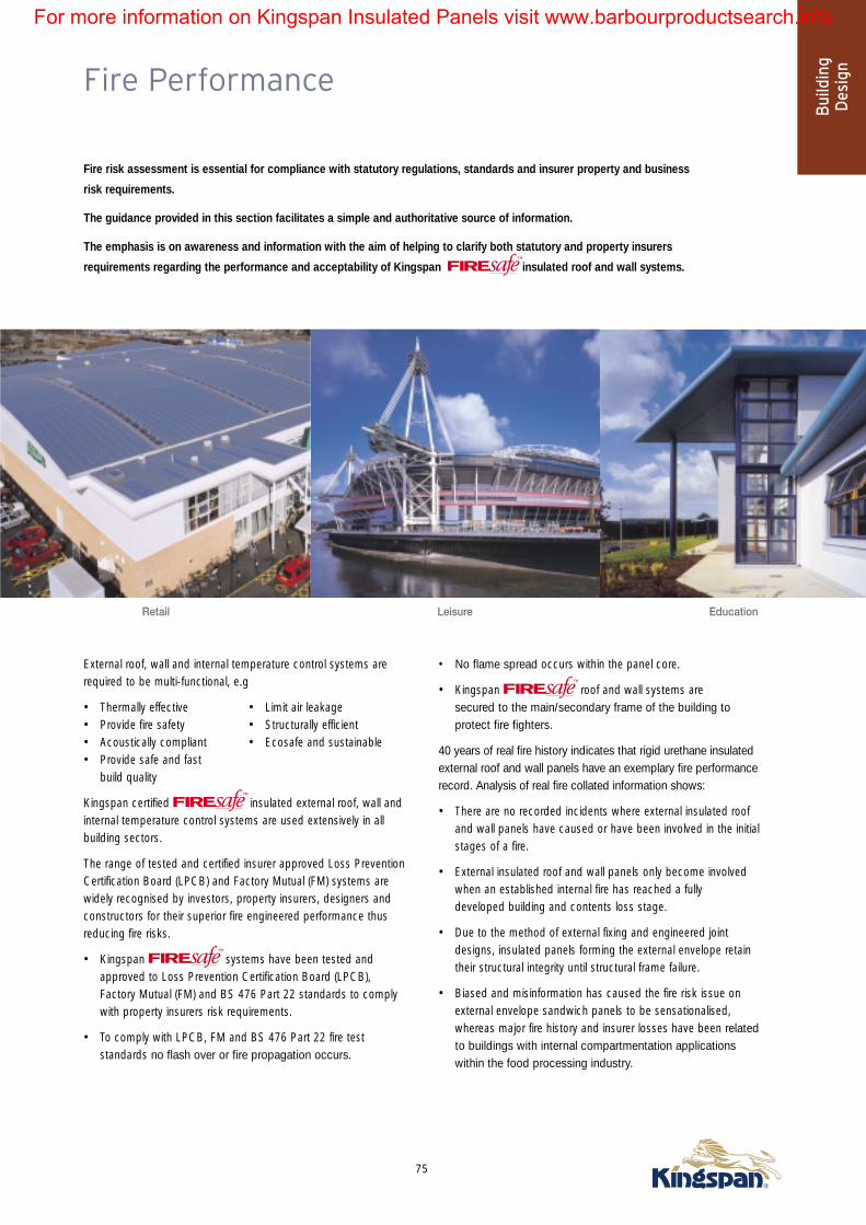
Fire Performance
Fire risk assessment is essential for compliance with statutory regulations, standards and insurer property and business
risk requirements.
The guidance provided in this section facilitates a simple and authoritative source of information.
The emphasis is on awareness and information with the aim of helping to clarify both statutory and property insurers
requirements regarding the performance and acceptability of Kingspan insulated roof and wall systems.
75
Bui
ldin
gD
esig
n
Retail Leisure Education
External roof, wall and internal temperature control systems arerequired to be multi-functional, e.g
• Thermally effective • Limit air leakage• Provide fire safety • Structurally efficient• Acoustically compliant • Ecosafe and sustainable• Provide safe and fast
build quality
Kingspan certified insulated external roof, wall andinternal temperature control systems are used extensively in allbuilding sectors.
The range of tested and certified insurer approved Loss PreventionCertification Board (LPCB) and Factory Mutual (FM) systems arewidely recognised by investors, property insurers, designers andconstructors for their superior fire engineered performance thusreducing fire risks.
• Kingspan systems have been tested and approved to Loss Prevention Certification Board (LPCB), Factory Mutual (FM) and BS 476 Part 22 standards to complywith property insurers risk requirements.
• To comply with LPCB, FM and BS 476 Part 22 fire test standards no flash over or fire propagation occurs.
• No flame spread occurs within the panel core.
• Kingspan roof and wall systems are secured to the main/secondary frame of the building to protect fire fighters.
40 years of real fire history indicates that rigid urethane insulatedexternal roof and wall panels have an exemplary fire performancerecord. Analysis of real fire collated information shows:
• There are no recorded incidents where external insulated roof and wall panels have caused or have been involved in the initialstages of a fire.
• External insulated roof and wall panels only become involved when an established internal fire has reached a fully developed building and contents loss stage.
• Due to the method of external fixing and engineered joint designs, insulated panels forming the external envelope retain their structural integrity until structural frame failure.
• Biased and misinformation has caused the fire risk issue on external envelope sandwich panels to be sensationalised, whereas major fire history and insurer losses have been relatedto buildings with internal compartmentation applications within the food processing industry.
For more information on Kingspan Insulated Panels visit www.barbourproductsearch.info

Fire Performance - Statutory Requirements
76
Statutory RequirementsStatutory fire safety legislation is primarily concerned with theprotection of people from death or injury in fire.
In the United Kingdom fire safety in buildings is controlled undervarious statutory instruments.
The main requirements arise from:
a) Building Regulations:
(i) England and Wales –
The Building Regulations 2000 (as amended)
(ii) Scotland – The Building Standards
(Scotland) Regulations 1990 (as amended)
(iii) Northern Ireland – The Building
Regulations (Northern Ireland) 1994
b) Fire precautions Act 1971 (as amended)
c) Fire Precautions (Workplace) Regulations 1997 (as amended 1999)
d) Construction (Design and Management) Regulations 1994
Building RegulationsThe Building Regulations apply to the design and construction ofnew buildings and also to existing buildings if a material alterationor material change of use is being made. It is the buildingregulations that are likely to have the main impact on the requiredfire performance of external cladding systems.
England, Wales, Scotland and Northern Ireland each have theirown building regulations and each country has its own set ofguidance documents for fire safety. It is important to recognisethat the guidance applicable in Scotland can be significantlydifferent to that applicable in England and Wales or NorthernIreland.
Building Regulations for England, Walesand Northern IrelandThe fire safety aspects of building design and construction inEngland and Wales are controlled by the requirements of theBuilding Regulations, 2000 (requirements B1 to B5).Theregulations are set out in functional form and set performanceobjectives rather than prescribing specific fire safetymeasures.These functional requirements can be met by;
a) following the recommendations set out in ApprovedDocument B
or
b) adopting an alternative approach (e.g. using fire engineering).
Whilst there is no overriding requirement to adopt therecommendations given in the Approved Document thisrepresents the most common approach, particularly for relativelysmall and straightforward buildings. However, fire engineeringtechniques are increasingly being applied in large or complexdevelopments.
Fire Precautions LegislationThe Fire Precautions Act and Fire Precautions (Workplace)Regulations are primarily intended to ensure that an acceptablelevel of safety is achieved during occupation of the building.
Generally this legislation will not have a direct effect upon thedesign of the structure or the specification of external claddingsystems.
The Fire Precautions Act contains a statutory bar that preventsadditional structural measures being required if the building hasbeen previously approved under building regulations.Therefore thisact is likely to have little impact on the specification of the externalcladding.
The Fire Precautions (Workplace) Regulations (FPW) require that arisk assessment be carried out to identify any potential fire hazardsin a workplace and to evaluate the risks to employees. Employersare required to take steps to reduce any unacceptable risks.Construction materials complying with current building regulationswould normally be acceptable but there may be circumstanceswhere additional fire precautions are appropriate (e.g. duringmaintenance procedures).
Construction (Design and Management)RegulationsThe Construction (Design and Management) Regulations 1994(CDM) relate to all aspects of construction and affect all thoseconcerned in the construction process.The CDM regulationsimpose specific obligations on designers to consider mattersrelating to safety during construction and subsequent maintenanceof the completed building.
The FPW and CDM regulations require that any foreseeable risksassociated with the construction and the continuing operation of abuilding are identified and effectively managed and controlled.Guidance on appropriate management procedures should beincorporated into the project’s operational and maintenancemanual.
For more information on Kingspan Insulated Panels visit www.barbourproductsearch.info

Fire Performance - Building Regulations for England, Wales and Northern Ireland
77
Bui
ldin
gD
esig
n
The fire safety aspects of building design and construction inEngland and Wales are controlled by the requirements of theBuilding Regulations, 2000 (requirements B1 to B5).Theregulations are set out in functional form and set performanceobjectives rather than prescribing specific fire safetymeasures.These functional requirements can be met by;
a) following the recommendations set out in ApprovedDocument B or
b) adopting an alternative approach (e.g. using fire engineering).
Whilst there is no overriding requirement to adopt therecommendations given in the Approved Document thisrepresents the most common approach, particularly for relativelysmall and straightforward buildings. However, fire engineeringtechniques are increasingly being applied in large or complexdevelopments.
Northern IrelandThe design and construction for fire safety in buildings in NorthernIreland is controlled by the Building Regulations (Northern Ireland)1994. Recommended fire safety measures are detailed in Sections 1to 5 of Technical Booklet E for fire safety. There are some minordifferences between Technical Booklet E and Approved Document B
that applies in England and Wales. In particular the critical heightat which additional provisions regarding the external flame spreadclassification apply is 20m rather than the 18m stated in ApprovedDocument B. However in other respects the guidance given in thissection relating to Approved Document B will generally beapplicable.
Functional RequirementsThe functional requirements of the Building Regulations requirethat ‘reasonable’, ‘adequate’ and ‘appropriate’ steps be taken toensure health and safety of people in and around buildings.These requirements are summarised below.
EscapeRequirement B1 requires that adequate escape routes beprovided to enable the occupants to reach a safe location outsideof the building. Suitable means of giving warning of a fire are alsorequired.
Fire Spread Across SurfacesRequirement B2 requires that materials used as wall and ceilinglinings do not promote rapid fire spread or unduly contribute to theheat produced by a fire.
Building StructureRequirement B3 requires that appropriate measures be taken toensure that:• the structural stability of the building will be maintained;
• a wall between two buildings will resist fire spread between thebuildings;
• buildings are subdivided into compartments to restrict the size of a fire;
• unseen voids are subdivided to inhibit hidden fire spread.
These objectives are generally achieved by providing fire resistingconstructions.
External Fire SpreadRequirement B4 is primarily intended to prevent the spread of firefrom one building to another as a result of heat radiation orairborne burning brands. This is generally achieved by:
a) controlling external surfaces of walls and roofs;
b) providing fire resisting external walls when appropriate.
Facilities for the Fire ServicesRequirement B5 requires that reasonable facilities are available toenable fire appliances to gain access to the building and to enablefire fighters to protect life.
For more information on Kingspan Insulated Panels visit www.barbourproductsearch.info

78
Statutory fire safety legislation is primarily concerned withthe protection of people from death or injury in fire.
However, a fire that causes no physical injuries can stillhave potentially devastating effects on the viability of abusiness in terms of:
• loss of stock • loss of records
• direct damage to building • lost production
• lost customers • damage to public image
Therefore, where a fire has the potential to have a substantialimpact on the viability of a business or cause large financial lossesconsideration should be given to additional fire protectionmeasures over and above those necessary to satisfy the minimumstatutory requirements. Insurance premium discounts may beavailable where a high standard of fire protection is provided.
In some cases insurance cover may not be readily available unlessfire protection measures exceed the minimum requirements ofbuilding regulations.
Myths & Misinformation - Insurance PremiumsThe property insurance market has been characterised by generalconfusion resulting from conflicting information, misinformation,misreporting and myths.
Probably the most damaging myth in relation to polyurethanepanels relates to comments made about building insurancepremium increases of up to 1500% and statements that somebuildings have become uninsurable. The reality is that thesedramatic premium increases relate exclusively to buildingscontaining polystyrene panels.
There is no justification whatsoever for such premium increases onbuildings clad with polyurethane or polyisocyanurate panels.
Kingspan Fire Engineering Department is available to supportbuilding owners and tenants to assess fire risk issues and helpin discussions with brokers and insurers.
For more information on Kingspan Insulated Panels visit www.barbourproductsearch.info

Property & Business Protection
79
Bui
ldin
gD
esig
n
Fire FightingA further myth is that fire brigades will not enter a building cladwith composite panels. This is totally untrue, a situation confirmedby our discussions with fire-fighters. The reality is that the firebrigade will perform a dynamic risk assessment on arrival at thefire - the result of which will determine their actions. Obviously,panel system collapse and internal flashover is the biggest fear offire-fighters - this is a particularly important consideration in relationto internal panel systems.
The reality is that buildings clad in structurally supported (mechanically-fixed) external panels do not present a specifichazard, as the panels will not collapse until the structural steelworkframe collapses.
In an article published in Fire Prevention and Fire Engineers Journal inDecember 2002 the UK’s Building Research Establishment state ‘Firestatistics show that external claddings constructed from sandwichpanels tend not to be a major fire risk, particularly if the chances ofan arson attack can be reduced and its effect minimised.’
Center Parcs FireRecent misreporting, led to another damaging myth that the estimated £100m Center Parcs fire - possibly the largest fire lossin the UK for many years - was caused by composite panels,which was patently not the case. The true position was clarifiedby Paul Hayden, Assistant Chief Fire Officer of Suffolk CountyFire Service in a report in the August 2002 issue of FirePrevention and Fire Engineers Journal;
“The key contributory factor to structural fire spread was theextensive flat roof construction. Although investigators describeit as ‘sandwich’ construction, it was not constructed of pre-formed sandwich panels, but a built-up layer of plasterboardinternal lining, polystyrene insulation, timber boards and toppedoff with roofing felt and bitumen”.
Sahib Foods - Architects Professional Indemnity CoverIn a recent high court judgement on 3rd March 2003 the architectresponsible for specifying the use of polystyrene (EPS) coredpanels in a high risk cooking area has been found liable for thelosses that occurred in a subsequent fire. The cost to SahibFood’s insurers, Norwich Union, at the time was £17M.
The facts of this case are clear. Polystyrene panels were specifiedand used throughout the premises of Sahib foods in arefurbishment carried out in 1994 to 1995. A fire occurred inJanuary 1998 that spread rapidly throughout the factory causing atotal loss and led to the closure of the business. The source of thefire was a cooking area that involved frying operations using gasfired equipment.
One of the key issues influencing the judgement was that thearchitects conceded that at the time of the specification in 1994they knew the same about the fire performance of compositepanels as they know at the present time. In his judgement HHJPeter Bowsher noted: ‘It is agreed that in 1994, the year withwhich we are concerned, knowledge of the risk of the use EPSpanels in relation to food factory fires was developing in thearchitects profession……’.
This judgement was based on the particular facts of the case.The case relates only to the specification of polystyrene panels incooking areas - universally acknowledged as high risk processesfor many years. There have been a relatively large number of firesin similar circumstances in food factories. Statistics published bythe Building Research Establishment state ‘Fire losses in foodfactories over the period 1991 to 1999 represent an average lossper year of £27M. Most of the food factory fires over this periodresulted from cooking risks or malfunction of equipment’. It isinteresting to note that insurer losses in food factory fires in 1998and 1999 were £46M and £64M respectively. We believe that thevast majority of these losses were in factories with internalpolystyrene panel systems.
In stark contrast - the historical fire performance and insuranceloss statistics relating to the use of Kingspan polyurethane andpolyisocyanurate panels in the external envelope has beenexcellent. There is no evidence whatsoever to suggest thatKingspan panel systems are not fit for the purpose that they arerecommended and there is no link with higher insurer losses. Thisis proven by detailed insurer loss statistics and case studies onfires in buildings clad with polyurethane panels. In addition to firesafety the specification of Kingspan panels gives a number ofother important benefits to the client.
The implications for Architects’ PI insurance cover are unclearbut it important to understand that the judgement refers onlyto polystyrene panels in a high risk food sector applications.
Architects’ and their PI insurance cover is not at risk whenspecifying and using Kingspan’s insurer approved
insulated external roof, wall and internaltemperature control systems.
For more information on Kingspan Insulated Panels visit www.barbourproductsearch.info

Property & Business Protection
80
The Non-Combustibility MythIn recent years huge confusion has been caused by panelmanufacturers and their raw material suppliers making claim andcounter claim about the non-combustibility or otherwise of theirown and their competitors panel systems and core materials.The simplest way of looking at this issue is to address theinsulation core and the panel system separately.
The Insulation CoreThe definition of non-combustibility according to British Standardscan be found in BS 476 Part 4. This is a small scale furnace testwhere the sample is burnt at a high temperature and contribution totemperature rise and flaming is assessed. Polystyrene, polyurethane,polyisocyanurate and most rock fibre cores used in compositepanels are believed to be combustible according to this test.Rock fibre can be defined as combustible because of the relativelyhigh levels of organic binders used to glue the fibres together.
The Panel SystemIn the case of polystyrene and rock fibre panels adhesives are usedto adhere the steel facing to the insulation. In rock fibre panels theadhesive is normally polyurethane and levels of adhesive can bequite large to ensure a good bond and minimise the risk ofdelamination. As a direct result panels with a rock fibre corecannot be rated as completely non-combustible.
Combustibility of Installed Panel SystemsThe reality is that all panel systems have varying levels ofcombustibility because all contain combustible materials. The onlyreliable way of assessing panel system combustibility is to base ajudgement on testing the entire system. Tests and standards suchas LPS 1181, LPS 1208 and FM 4880 are ideal in this respect.The varying levels and grades of performance defined by thesetests allow the specific panel system performance to be matchedto the specific risk.
The real issue is not directly related to the combustibility of thepanel system or core - all have combustible elements. The realissue is related to how a specific system will perform in a realfire scenario and whether it acts as a non-combustible buildingelement by not contributing to fire propagation.
Ignitability of Insurer Approved PIR InsulantOne concern raised by insurers is the potential for exposedinsulation in ‘real’ situations. The reality is that any insulation panelsystem is likely to be damaged or modified after installation andthis may lead to exposure of the core – and example would bewhere a hole has been cut in the panel for new pipework,ductwork or electrical services. Such modifications are often notfinished correctly and are perceived to provide an easy entry pointfor fire. The question is how big is the risk?
The fact is that insurer approved PIR is very difficult to ignite.The images above cover the effect of a high intensity propanetorch on exposed PIR after the metal facings have been removed.
The propane torch generates a temperature of over 1000°C.The images show the effect after 30 minutes exposure and are agood demonstration of how the PIR forms a strong carbonaceouschar that protects the insulation core from ignition. When theburner is removed after 30 minutes the core self extinguishes.
Good practice dictates that any panel damage is repaired or sitemodifications are installed correctly – however, the propane torchtest does demonstrate that insurer approved PIR does notignite and the exposed core does not present a fire hazard.
After 30 minutes at over 1000°C
Section cut through the thickness of thepanel after 30 minutes exposureshowing that the char occurs only in thearea of direct flame impingement andthere is no fire propagation.
For more information on Kingspan Insulated Panels visit www.barbourproductsearch.info