eliminating flow induced birefringence and minimizing thermally induced residual stresses in...
TRANSCRIPT

This article was downloaded by: [Princeton University]On: 13 November 2014, At: 22:50Publisher: Taylor & FrancisInforma Ltd Registered in England and Wales Registered Number: 1072954 Registered office: MortimerHouse, 37-41 Mortimer Street, London W1T 3JH, UK
Polymer-Plastics Technology and EngineeringPublication details, including instructions for authors and subscription information:http://www.tandfonline.com/loi/lpte20
ELIMINATING FLOW INDUCED BIREFRINGENCE ANDMINIMIZING THERMALLY INDUCED RESIDUAL STRESSESIN INJECTION MOLDED PARTS*
Ming Chen a , Donggang Yao a & Byung Kim ba Department of Mechanical & Industrial Engineering , University of Massachusetts ,Amherst, Massachusetts, 01003, U.S.A.b Department of Mechanical & Industrial Engineering , University of Massachusetts ,Amherst, Massachusetts, 01003, U.S.A.Published online: 14 Feb 2007.
To cite this article: Ming Chen , Donggang Yao & Byung Kim (2001) ELIMINATING FLOW INDUCED BIREFRINGENCE ANDMINIMIZING THERMALLY INDUCED RESIDUAL STRESSES IN INJECTION MOLDED PARTS* , Polymer-Plastics Technology andEngineering, 40:4, 491-503, DOI: 10.1081/PPT-100002072
To link to this article: http://dx.doi.org/10.1081/PPT-100002072
PLEASE SCROLL DOWN FOR ARTICLE
Taylor & Francis makes every effort to ensure the accuracy of all the information (the “Content”) containedin the publications on our platform. However, Taylor & Francis, our agents, and our licensors make norepresentations or warranties whatsoever as to the accuracy, completeness, or suitability for any purpose ofthe Content. Any opinions and views expressed in this publication are the opinions and views of the authors,and are not the views of or endorsed by Taylor & Francis. The accuracy of the Content should not be reliedupon and should be independently verified with primary sources of information. Taylor and Francis shallnot be liable for any losses, actions, claims, proceedings, demands, costs, expenses, damages, and otherliabilities whatsoever or howsoever caused arising directly or indirectly in connection with, in relation to orarising out of the use of the Content.
This article may be used for research, teaching, and private study purposes. Any substantial or systematicreproduction, redistribution, reselling, loan, sub-licensing, systematic supply, or distribution in anyform to anyone is expressly forbidden. Terms & Conditions of access and use can be found at http://www.tandfonline.com/page/terms-and-conditions

POLYM.–PLAST. TECHNOL. ENG., 40(4), 491–503 (2001)
ELIMINATING FLOW INDUCEDBIREFRINGENCE AND MINIMIZINGTHERMALLY INDUCED RESIDUAL
STRESSES IN INJECTIONMOLDED PARTS∗
Ming Chen, Donggang Yao, and Byung Kim†
Department of Mechanical & Industrial Engineering, Universityof Massachusetts, Amherst, Massachusetts 01003
ABSTRACT
Eliminating flow-induced birefringence and stresses and re-ducing thermally induced stresses in the injection molded partshave been studied using rapid thermal response (RTR) moldingtechnique. In the RTR molding, mold surface temperature can berapidly raised above Tg in the filling stage, while the normal injec-tion molding cycle time is still maintained. Therefore, the melt canfill the cavity at temperatures above Tg, which enables the flow-induced stresses to relax completely in a short time after fillingand before vitrification. Residual stresses and birefringence in aRTR molded strip specimen are compared with the conventionalmolded parts by applying layer removal method and retardationmeasurement. For the material (Monsanto©R Lustrex Polystyrene)
∗Any opinions, findings, and conclusions or recommendations expressed in this publicationare those of the authors and do not necessarily reflect the views of the National ScienceFoundation.†Corresponding author. Fax: 413-545-1027; E-mail: [email protected]
491
Copyright C© 2001 by Marcel Dekker, Inc. www.dekker.com
Dow
nloa
ded
by [
Prin
ceto
n U
nive
rsity
] at
22:
50 1
3 N
ovem
ber
2014
ORDER REPRINTS
492 CHEN, YAO, AND KIM
and process conditions chosen, the birefringence level decreasedas the RTR temperature approached and exceeded the glass transi-tion temperature until it almost disappeared at a RTR temperatureof 180◦C. Reduction of magnitude and shift of peak location wereobserved in the gapwise stress profile for RTR molded specimen.
Key Words: Injection molding; Residual stresses; Birefringence;Mold heating
INTRODUCTION
Injection molding is extensively used in the net-shaped production of plasticparts due to its capability to meet requirement of stringent dimensional accuracyand short cycle time. During the injection-molding process, the polymer undergoessimultaneous mechanical and thermal influences in the fluid, rubbery, and glassystates. Such effects introduce residual stresses and strains into the final product,resulting in part flaws such as warpage, molecular orientation, or birefringence.Residual stresses can be divided into flow-induced stresses and thermal-inducedstresses (1). First, visco-elastic flow of the melt during filling and post-filling stageof the process cause frozen-in flow-induced stresses. These stresses correspondwith the orientation of the macromolecules. Second, differential shrinkage duringcooling, both inside the mold and after demolding causes the residual thermalstresses. It is found that the flow-induced stresses are an order of magnitude smallerthan the thermal stresses (2). However, they induce anisotropy of several properties,because of the different orientations in the direction parallel and perpendicular tothe flow direction. On the other hand, the residual thermal stresses may causewarpage and may induce environmental stress cracking.
A basic solution to improve the quality of plastic parts is to heat the moldsurface so that the incoming material does not vitrify at the mold surface. Witha heating temperature higher than Tg and the heating time more than the longestrelaxation time, the flow induced birefringence and stresses can be eliminated.Early in 1963, Johnson (3) revealed the utility of heated molds allowing the flow-induced orientation to relax once the mold cavity is filled. By applying a passiveinsulation layer on the surface of the cavity, Kim (4), Liou and Suh (5) implementedthe idea of Low Thermal Inertia Molding (LTIM). The freezing of the polymercould be prevented during the filling stage, allowing the flow-induced stresses torelax prior to solidification. Kim and Roth (6) used high performance thermo-electric devices in the LTIM cavity. Residual stresses were indirectly evaluatedusing the critical fracture energy (Jc) and a 15% reduction in Jc was obtainedwith this method. Jansen and coworkers (7–9) constructed a fast response heatingelement and studied its influence on the birefringence distribution in injection
Dow
nloa
ded
by [
Prin
ceto
n U
nive
rsity
] at
22:
50 1
3 N
ovem
ber
2014
ORDER REPRINTS
BIREFRINGENCE AND RESIDUAL STRESSES 493
molded parts. The heating elements achieved an increase of 80◦C within 0.3 sand thus had a small effect on the total cycle time. With a heating pulse of 2 s,the birefringence is seen to reduce by a factor of three while for surface residualstresses, the reduction is by a factor of about two.
Although the idea of heating injection molds is not new, its practical appli-cation is still rarely found due to either thermal or mechanical problem. Currenttechnology reported still have difficulty in molding engineering resin such as poly-carbonate and polybutylene-terephthalate, in which the mold surface temperatureneeded to be heated in excess of 200◦C rapidly. To ensure the surface finish andquality in final parts, homogeneous temperature field is essentially important inthe mold heating process. With the above issues addressed, a new technologyso called Rapid Thermal Response (RTR) molding technique is developed towardeliminating flow induced birefringence and minimizing thermally induced stressesdue to cooling.
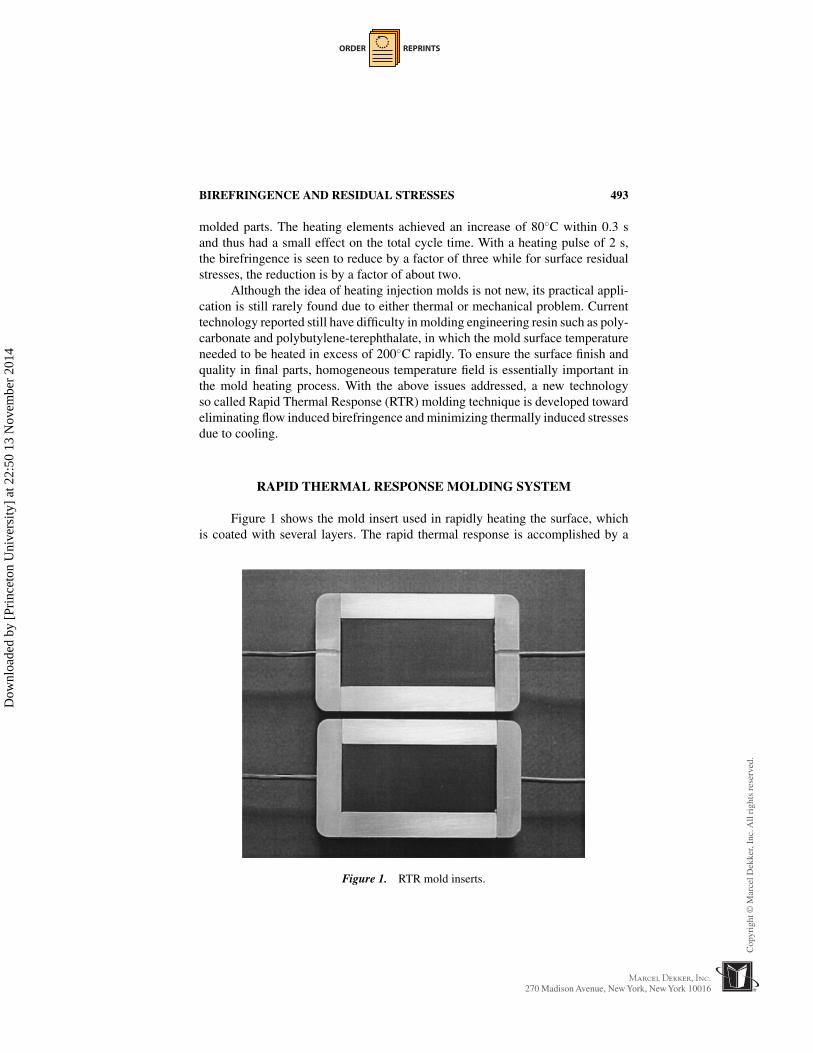
RAPID THERMAL RESPONSE MOLDING SYSTEM
Figure 1 shows the mold insert used in rapidly heating the surface, whichis coated with several layers. The rapid thermal response is accomplished by a
Figure 1. RTR mold inserts.
Dow
nloa
ded
by [
Prin
ceto
n U
nive
rsity
] at
22:
50 1
3 N
ovem
ber
2014

ORDER REPRINTS
494 CHEN, YAO, AND KIM
Figure 2. Experimental thermal response of the RTR heating and cooling surface.
thin metal heating layer, below which an oxide layer provides the thermal andelectrical insulation from the steel mold base. On the top surface, a thin Teflonlayer is coated to provide protection and help de-molding.
A typical surface thermal response achieved by the RTR mold insert is shownin Figure 2. Temperature was heated from 50 to 250◦C in 2 s and cooled to 50◦C in 8s. Unlike the slower heating rate after initial temperature rise in Jason’s experiment(8), the linearly increasing surface temperature with respect to heating durationindicates the potential to reach very high temperature.
After the two mold inserts were tested and characterized, mold bases werecut out to accommodate these two inserts and form a mold, as shown in Figure 3.Closure of the two RTR inserts forms a rectangle mold cavity. The B-plate inserthas double side gates and runners that provide an option of either single gate fillingor double gate filling. The finished mold plates were placed into a set of MUD©R
U-frames and mounted to a Boy©R 30M injection molding machine.The experimental setup of the RTR injection molding system is shown in
Figure 4. The heating inserts get powered when the mold close signal is triggered.One of the problems in RTR molding control is the difficulty in accurate temper-ature monitoring, since thermocouple is difficult to be mounted directly on theinner mold surface. In the current study, a third identical RTR insert was used fortemperature monitoring purpose. The third insert has the same heating and coolingcharacteristics as the former two, and was placed outside of the molding systemon which thermocouple could be mounted.
Dow
nloa
ded
by [
Prin
ceto
n U
nive
rsity
] at
22:
50 1
3 N
ovem
ber
2014

ORDER REPRINTS
BIREFRINGENCE AND RESIDUAL STRESSES 495
Figure 3. RTR mold.
Figure 4. Experimental setup of RTR injection molding system.
Dow
nloa
ded
by [
Prin
ceto
n U
nive
rsity
] at
22:
50 1
3 N
ovem
ber
2014

ORDER REPRINTS
496 CHEN, YAO, AND KIM
Table 1. Process Setup of RTR Molding
Filling time (s) 0.5Holding time (s) 4.0RTR heating duration (s) 4.5RTR temperature raising time (s) 1.0Holding pressure (bar) 100
Table 1 shows the process setup of the RTR molding process. The moldsurface temperature is quickly raised and kept for a while to allow the flow-inducedmolecular orientation to relax. The entire heating duration is defined as the totalpower-on time. In this work, the RTR heating duration time is chosen as 4.5 s. Atypical heating and cooling response for this molding setup is shown in Figure 5.Mold surface temperature is raised from 50 to 250◦C within 2 s and cooled to50◦C in 9 s. Due to thermocouple response and controller scanning delay, thetemperature slightly overshot and oscillated around the setup temperature. Thisslight overshoot and oscillation will not infringe the birefringence elimination aslong as the lowest temperature is higher than Tg and the heating duration is morethan the longest relaxation time. The delay of the mold closing stage and the delayof the temperature rise were synchronized to ensure the entire filling stage and thefirst portion of the holding stage were under the RTR heating.
Figure 5. RTR mold surface temperature response.
Dow
nloa
ded
by [
Prin
ceto
n U
nive
rsity
] at
22:
50 1
3 N
ovem
ber
2014

ORDER REPRINTS
BIREFRINGENCE AND RESIDUAL STRESSES 497
Figure 6. Layer removal method.
STRESS AND BIREFRINGENCE MEASUREMENT
Layer Removal Method
Layer removal method is one of the most popular methods to measure resid-ual thermal stress in molded parts (1,10). This method is relatively easy to applyand provide stress distribution along the gap-wise direction. Treuting and Read(11) developed this method for determining residual stress in metal sheets. Isayev(12) has provided a list of examples, which have successfully extended this methodto polymeric materials.
In this method, thin layers are removed from one surface of a rectangularspecimen, and disturbing stress equilibrium, as shown in Figure 6. After layerremoval, the remaining specimen warps to the shape of a circular arc to reachstress equilibrium. Based on the measured curvature values, the gap-wise residualstress prior to layer removal can be calculated.
When a thin layer is removed from a surface, the stress equilibrium is dis-turbed. The internal stress distribution remains constant. But the total force andmoment acting on the cross-section no longer vanish and results
Fx (z) =∫ z
−hσx (z) dz;
Mx (z) =∫ z
−hσx (z′)
[z′ + h − z
2
]dz′;
(1)
where z is the remaining thickness, h is the half thickness, and Fx (z) and Mx (z)are the resulting force and moment in the x direction, respectively.
Dow
nloa
ded
by [
Prin
ceto
n U
nive
rsity
] at
22:
50 1
3 N
ovem
ber
2014
ORDER REPRINTS
498 CHEN, YAO, AND KIM
The same equation holds for the y direction with the subscripts x and yexchanged. From the above equations, the residual stress could be related with theresultant curvature, as follows:
σx (z) = − E
6(1 − ν2)
{(h + z)2
[dϕx (z)
dz+ ν
dϕy(z)
dz
]
+ 4(h + z)[ϕx (z) + νϕy(z)] − 2∫ h
z[ϕx (z′) + νϕy(z′)] dz′]
}(2)
where E is the young’s modulus, v is the Poisson’s ratio, and ϕx (z) and ϕy(z) arethe resulting curvature in the x and y direction, respectively.
Birefringence and Its Measurement
Birefringence is widely used for characterizing molecular orientation inamorphous and semi-crystalline polymers. It can provide general information ofmolecular orientation and stress distribution in polymer processing. The threemutually independent components of birefringence are �n = [(n11 − n22)2 +4n2
12]1/2, [n11 − n33], and [n22 − n33] where 1, 2, and 3 correspond to the flow,gapwise, and width directions of the cavity. These components of birefringenceare normally measured on a thin slice removed from the molded part and observedunder a polarizing microscope with a calibrated compensator.
According to Brewster’s law (13), the relationship between birefringenceand stress can be expressed as:[
σ 21 + 4σ 2
12]1/2 = C�n
σ1 − σ3 = C[n11 − n33], (3)
σ2 − σ3 = C[n22 − n33]
where C is the so-called stress optical coefficient.In this experiment, measurement of birefringence is accomplished using
StrainOptics©R PS100 Polarimeter system, as shown in Figure 7, to satisfy themeasurement requirement in ASTM D4093. This polarimeter system includes anilluminator, an analyzer, and a compensator. To analyze birefringence, the direc-tions of principal optical axes need to be determined first. Generally at the edge,the principal optical direction is parallel to the edge direction.
When the principal direction is unknown, the specimen is rotated until thepoint of interest becomes dark. In this position, the principal optical direction atthe point of interest is parallel to the Analyzer/Polarizer axis. After the principaloptical axes are determined, the compensator is introduced in the field of view,with its axis aligned with the principal direction in the specimen. The retardationproduced by the specimen and the compensator is additive, producing the shift of
Dow
nloa
ded
by [
Prin
ceto
n U
nive
rsity
] at
22:
50 1
3 N
ovem
ber
2014

ORDER REPRINTS
BIREFRINGENCE AND RESIDUAL STRESSES 499
Figure 7. Birefringence measurement setup (14).
color fringes at the point of interest. The wedge position of the compensator isadjusted until a black fringe shows at the point of interest on the sample. Blackfringe is observed when the compensator has an equal and opposite-sign retardationlevel at the point of interest on the sample. Thus, the reading on the compensatorprovides quantitative information of birefringence in the sample.
EFFECT OF RTR MOLDING ON RESIDUAL STRESSAND BIREFRINGENCE
Monsanto©R Lustrex Polystyrene was chosen as the molding material. Asingle gated flat strip is chosen as our specimen (80 × 35 × 3 mm), shown inFigure 8. Following the above retardation measurement procedures, birefringencelevel in specimen were determined. Figure 10a shows color fringe pattern in theconventional-molded specimen. Closely spaced color bands indicate that straingradient or orientation is substantial. Note that fringe order is higher near the gatethan that at the end of flow path.
Theoretically, there will be no flow-induced birefringence if the entire fillingis isothermal and such an isothermal stage is longer than the longest relaxationtime. It was difficult to create a true isothermal environment in the current RTRmolding due to lack of precise temperature control system. An alternative ap-proach used in this research is to guarantee mold surface temperature higher thanthe glass transition temperature during the filling stage. By varying the heatingtemperature and the heating duration, the effect of RTR molding condition on theflow birefringence can be characterized. Four different mold surface temperatures
Dow
nloa
ded
by [
Prin
ceto
n U
nive
rsity
] at
22:
50 1
3 N
ovem
ber
2014

ORDER REPRINTS
500 CHEN, YAO, AND KIM
Figure 8. Schematic illustration of specimen and coordiate systems.
were used to study the effect of RTR molding on birefringence. Four samples wereprepared before carrying out the birefringence measurement. The first one wasmolded using conventional mold temperature, i.e., not heated. However, the mea-sured birefringence of this first type might be different from that of parts moldedusing pure steel mold, since the RTR inserts provides thermal insulation at themold surface. The other three types of specimen were molded using three differentRTR temperatures, 100, 150, and 180◦C.
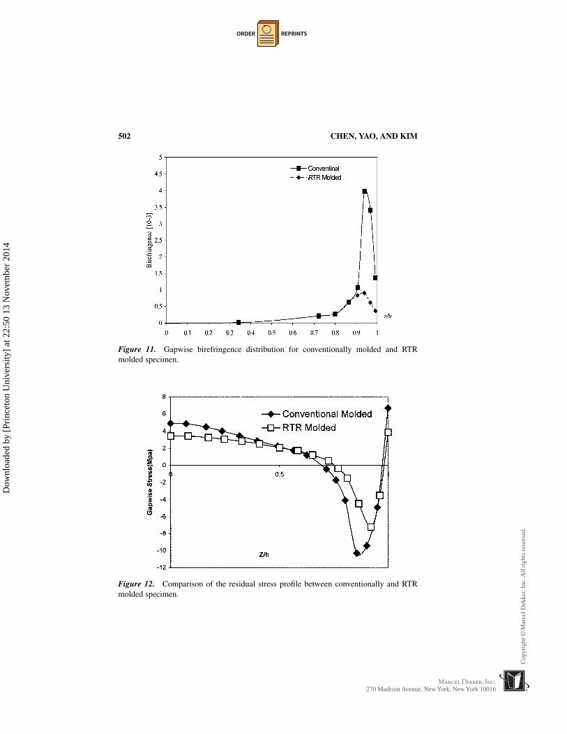
Comparison of birefringence in the same location of each part is illustratedin Figure 9. It is observed that the birefringence decreases as the mold surfacetemperature increases. Figure 10 shows the comparison of color fringe patternsbetween conventionally and RTR molded parts. Visibly dark fringe was foundacross the whole part when the RTR temperature reached 180◦C, which impliesthat the birefringence is close to zero in the large area from gate through the endof the flow path. Comparison of gap-wise birefringence �n distribution in ourspecimen is shown in Figure 11. Magnitude of the so-called shear maximum is re-duced by 75% in RTR molded part and its location essentially remains unchanged.The slight difference between our observations and Jason’s experiments (9) mayattribute to different insulation thickness used and different nature of polymerresin.
Gapwise stress distribution is measured by applying layer removal method.The comparison between stress distribution in conventional-molded and RTRmolded part is illustrated in Figure 12. Major differences in the gapwise stressprofile between conventional-molded and RTR molded part are found in the com-pression stress area, and tensile stress level in RTR molded part also decreasedcorrespondingly. It is observed that the magnitude of compression peak is reducedand its location shifts a little toward surface in RTR molded part.
Dow
nloa
ded
by [
Prin
ceto
n U
nive
rsity
] at
22:
50 1
3 N
ovem
ber
2014

ORDER REPRINTS
Figure 9. Comparison of overall birefringence between conventionally and RTR moldedparts.
Figure 10. Comparison of fringe patterns between conventionally and RTR molded parts.
Dow
nloa
ded
by [
Prin
ceto
n U
nive
rsity
] at
22:
50 1
3 N
ovem
ber
2014
ORDER REPRINTS
502 CHEN, YAO, AND KIM
Figure 11. Gapwise birefringence distribution for conventionally molded and RTRmolded specimen.
Figure 12. Comparison of the residual stress profile between conventionally and RTRmolded specimen.
Dow
nloa
ded
by [
Prin
ceto
n U
nive
rsity
] at
22:
50 1
3 N
ovem
ber
2014

ORDER REPRINTS
BIREFRINGENCE AND RESIDUAL STRESSES 503
CONCLUSIONS
Effects on molecular orientations in terms of birefringence and residual stressprofile using a rapid thermal response (RTR) molding technique were evaluated.Experiments show that the birefringence level in the RTR molded Polystyrenepart keeps decreasing as the RTR temperature approaches and exceeds the glasstransition temperature. A dark area was observed across the whole area of RTRmolded part when the specimen was placed between two cross polarized plates.Also reduction of magnitude was observed in the gapwise stress profile for RTRmolded specimen.
ACKNOWLEDGMENTS
The authors are grateful to Professor J. E. Sunderland and Professor IanR. Grosse from University of Massachusetts, Amherst for their valuable sugges-tions. The authors also thank to Mr. George Reid and Mr. Anthony Hoynoski fortheir assistance in layer removal experiments. The authors gratefully acknowl-edge financial support from the National Science Foundation under Grant No.DMI-9713519.
REFERENCES
1. Malloy, R. Plastic Part Design for Injection Molding; Hanser Publishers:New York, 1994.
2. Struik, L.C.E. Polym. Eng. Sci. 1978, 18, 799.3. Johnson, L.I. Modern Plast. 1963, 40, 111.4. Kim, B.H. Ph.D. Thesis, Massachusetts Institute of Technology, 1983.5. Liou, M.J.; Suh, N.P. Polym. Eng. Sci. 1989, 29, 441.6. Kim, B.H.; Roth, C. Polym. Plast. Technol. Eng. 1988, 27, 467.7. Jansen, K.M.B. Int. J. Heat Mass Transfer 1995, 38, 309.8. Jansen, K.M.B.; Flaman, A.A.M. Polym. Eng. Sci. 1994, 34, 894.9. Jansen, K.M.B.; Flaman, A.A.M. Polym. Eng. Sci. 1994, 34, 898.
10. Daly, H.B.; Nguyen, K.T.; Sanschagrin, B.; Cole, K.C. J. Inj. Mol. Tech.1998, 2, 59.
11. Read, W.T.; Treuting, R.G. J. Appl. Phys. 1951, 22, 130.12. Isayev, A.I. Ed. Injection and Compression Molding Fundamentals; Marcel
Dekker Inc.: New York, 1987.13. Riande, E.; Saiz, E. Dipole Moments and Birefringence of Polymers; Prentice
Hall: Upper Saddle. River, NJ, 1992.14. ASTM D4093.
Dow
nloa
ded
by [
Prin
ceto
n U
nive
rsity
] at
22:
50 1
3 N
ovem
ber
2014

Order now!
Reprints of this article can also be ordered at
http://www.dekker.com/servlet/product/DOI/101081PPT100002072
Request Permission or Order Reprints Instantly!
Interested in copying and sharing this article? In most cases, U.S. Copyright Law requires that you get permission from the article’s rightsholder before using copyrighted content.
All information and materials found in this article, including but not limited to text, trademarks, patents, logos, graphics and images (the "Materials"), are the copyrighted works and other forms of intellectual property of Marcel Dekker, Inc., or its licensors. All rights not expressly granted are reserved.
Get permission to lawfully reproduce and distribute the Materials or order reprints quickly and painlessly. Simply click on the "Request Permission/Reprints Here" link below and follow the instructions. Visit the U.S. Copyright Office for information on Fair Use limitations of U.S. copyright law. Please refer to The Association of American Publishers’ (AAP) website for guidelines on Fair Use in the Classroom.
The Materials are for your personal use only and cannot be reformatted, reposted, resold or distributed by electronic means or otherwise without permission from Marcel Dekker, Inc. Marcel Dekker, Inc. grants you the limited right to display the Materials only on your personal computer or personal wireless device, and to copy and download single copies of such Materials provided that any copyright, trademark or other notice appearing on such Materials is also retained by, displayed, copied or downloaded as part of the Materials and is not removed or obscured, and provided you do not edit, modify, alter or enhance the Materials. Please refer to our Website User Agreement for more details.
Dow
nloa
ded
by [
Prin
ceto
n U
nive
rsity
] at
22:
50 1
3 N
ovem
ber
2014