electronics: communicating your design proposals · electronics: communicating your design...
TRANSCRIPT
Downloaded from www.secondarydandt.org – the website of Nuffield Design & Technology 1
Electronics: Communicating your designproposals
Communicating to the clientIn the world of business and industry, design proposals can only
be turned into products which can be sold if the designers
communicate their proposals effectively. Designers have to
communicate their ideas to clients and to manufacturers as
shown below.
The designerI work for a large company which
specialises in electronic-based products
such as sound systems, portable radios, and
electronic-based toys. I am part of the in-house team
of designers who develop new products. It is the
client who decides whether the design will be
produced or not, so we need to present our ideas as
effectively as possible.
In your work you may be both the designer and the manufacturer. You might even be the client too. Do
not fall into the trap of thinking you don’t need to communicate your ideas just because you know what
you are doing! You have to communicate your ideas so that they can be understood by other people.
You can then ask them for their advice and opinions about your proposals. You will also be able to judge
more clearly whether your design is exactly right, before you start making. You can use techniques in
this chapter to help you communicate ideas.
The clientI am the manager of the electronic products company. I and the rest of the
management team are always looking to enlarge our product range.
We employ a team of in-house designers. We have to be sure that the new
products which the design team present to us are what people will buy.
The manufacturerWhen a new product is proposed, I have to be involved at an early stage in
planning the manufacturing process. I need to be sure that the factory can
make the product quickly and efficiently to the required quality standard.
I also need to make sure that we can buy the electronic components
needed.
CRT 1
Downloaded from www.secondarydandt.org – the website of Nuffield Design & Technology 2
Electronics: Communicating your designproposalsRenderingDesigners use presentation drawings to show what a product will look like. They use a technique called
rendering which shows surface textures. You can use a wide range of media to do this.
Felt marker renderingTo use markers well you will need to practise before
working on a special piece of work.
Here are some tips which will help you.
1 Work quickly and evenly - don’t rest the pen on the
paper.
2 Don’t worry about going over the edges of your
drawing (see 3).
3 Cut out your finished drawing and remount it to obtain
clear outlines.
4 Use coloured pencils to add details and white pencil
for reflections.
5 Use white paint for highlights.
6 Use only a limited range of colours or a variety of
shades of the same colour.
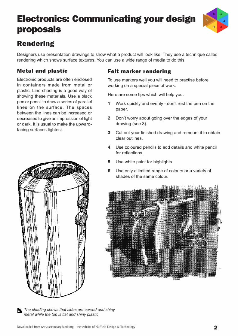
Metal and plasticElectronic products are often enclosed
in containers made from metal or
plastic. Line shading is a good way of
showing these materials. Use a black
pen or pencil to draw a series of parallel
lines on the surface. The spaces
between the lines can be increased or
decreased to give an impression of light
or dark. It is usual to make the upward-
facing surfaces lightest.
The shading shows that sides are curved and shiny
metal while the top is flat and shiny plastic
Downloaded from www.secondarydandt.org – the website of Nuffield Design & Technology 3
Electronics: Communicating your designproposals
CRT 1
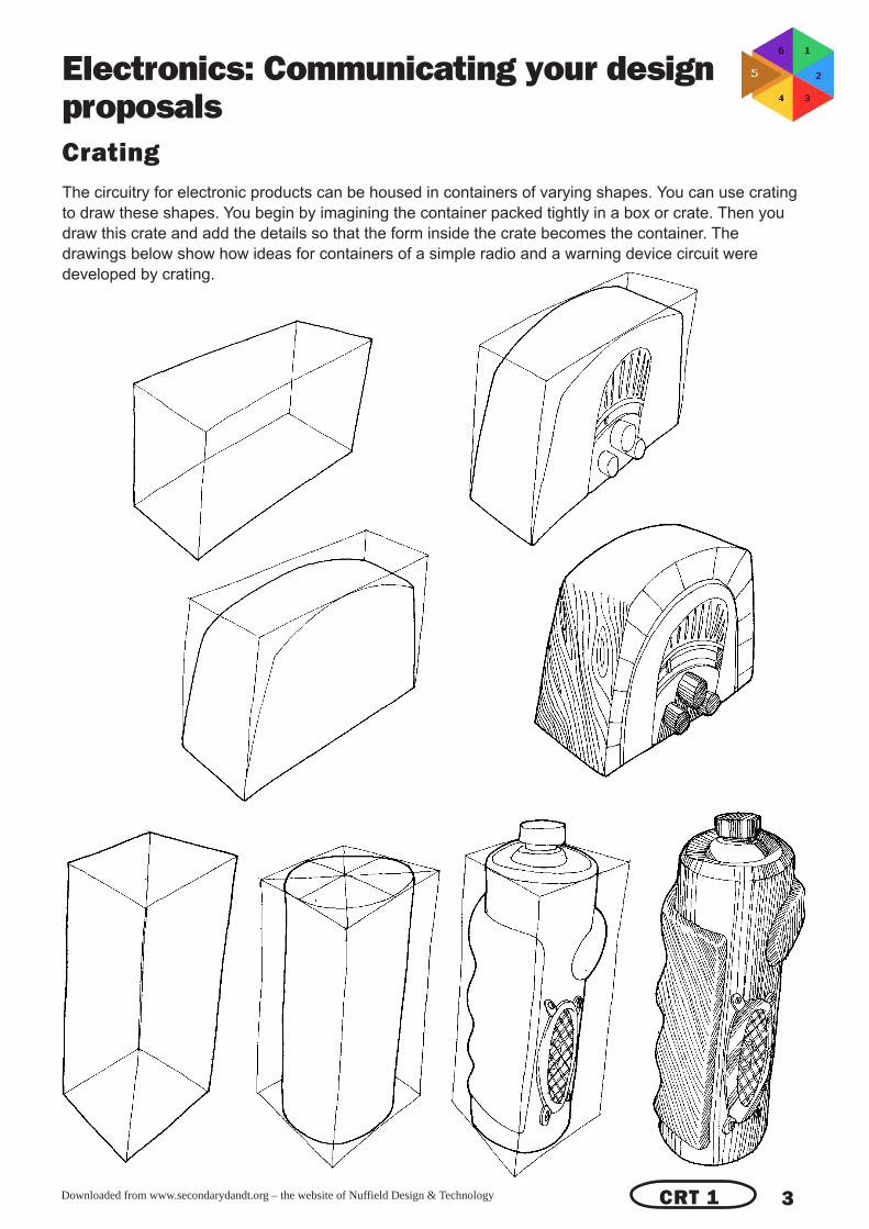
CratingThe circuitry for electronic products can be housed in containers of varying shapes. You can use crating
to draw these shapes. You begin by imagining the container packed tightly in a box or crate. Then you
draw this crate and add the details so that the form inside the crate becomes the container. The
drawings below show how ideas for containers of a simple radio and a warning device circuit were
developed by crating.

Downloaded from www.secondarydandt.org – the website of Nuffield Design & Technology 4
Electronics: Communicating your designproposals
3 Use a ruler to mark off the correct
measurements to construct your drawing.
4 Adding final detail.
1 Draw a base line and construct the
nearest corner of the object at 30° to the
base line.
Base line
2 Construct the crate by drawing lines
parallel to the three corner lines.
Isometric drawingIsometric means ‘equal measure’. In isometric drawings lines of equal length along the axes in the object
being drawn appear as such in the drawing. This method of drawing is suitable for computer-aided
design (CAD) where drawings are entered into the computer as a series of numbers or measurements.
You can draw this way by following the steps illustrated using a 60/30 set square.
CRT 1

Downloaded from www.secondarydandt.org – the website of Nuffield Design & Technology 5
Electronics: Communicating your designproposalsCommunicating costsYou will need to show the costs of the
components, the cost of producing a circuit
board which holds the components, and the
cost of the container for the product.
Costing electronic componentsand circuit constructionThe chart below lists a range of components
which you are likely to use, and their
approximate costs. You can use this to
estimate the cost of components.
Costing the containerThe chart on the right lists some ways of
making containers for electronic products in
school, with information about cost and
additional features you may need to consider
when deciding on your container.
Key: ▲ = less than £ 0.20
◆ = between £ 0.30 and £ 0.70
● = between £ 0.80 and £ 1.30
■ = between £ 1.40 and £ 2.00
Method Application Costs Comments
From flat For single Low Rapid
sheets of prototypes Easy to do
polystyrene Can be sprayed for extra realism
glued Limited range of forms possible
together Not very robust
From sheets For single Medium Rapid
of acrylic prototypes Quite easy to do
glued Can be sprayed for extra realism
together Wider range of forms available
through use of strip heating
Robust
From For short Medium Rapid but mould making is
polystyrene runs very time consuming
sheet Moderately easy to do
vacuum Can be sprayed for extra realism
formed Wide range of curved forms
possible
Quite robust
From For single Low Time consuming
aluminium prototypes Difficult to do
sheet pop Can be sprayed for extra realism
riveted Limited range of forms possible
together Very robust
Using ready For single Low Rapid
made tubing prototypes Moderately easy to do
Can be sprayed for extra realism
Wide range of forms possible
Very robust
Discrete components Integrated circuits Output devices Circuit construction
Resistor ▲ 555 timer ◆ Relay ■ Perforated board 100 mm x 50 mm ◆
Thermistor ▲ 741 op amp ◆ Low power motor ◆ Strip board 100 mm x 50 mm ●
Diode ▲ 7404 AND gate ◆ Geared motor ■ Printed circuit board
Low power transistor ▲ 7402 NOR gate ◆ Buzzer ◆ 100 mm x 50 mm (photo-resist) ■
High power transistor ◆ 7493 binary counter ◆ Pico sounder ● Printed circuit board
Electrolytic capacitor ◆ 7475 latch ◆ Low voltage lamp ◆ 100 mm x 50 mm (copper clad) ◆
Polyester capacitor ▲ 4056 7-segment driver ◆ LED ◆
Tuning capacitor ◆
LDR ◆

Downloaded from www.secondarydandt.org – the website of Nuffield Design & Technology 6
Electronics: Communicating your designproposals
CRT 2/3
Orthographic projectionYou should use the drawing system called orthographic projection for accurate scale drawings of
the casings for electronic products. These drawings are called working drawings and are based on
square-on views of the object. As you can see» you can obtain six square-on views of a portable
radio/tape player.
Usually you only need to draw three views to give enough detail about your design. There are two ways
of arranging these views» as shown below. They are called first-angle projection and third-angle
projection. Each has its own symbol as shown. You must always show whether your plans are first- or
third-angle projections.
Right
side
bottom
front
left
side
top back
First angle projection Third angle projection
Downloaded from www.secondarydandt.org – the website of Nuffield Design & Technology 7
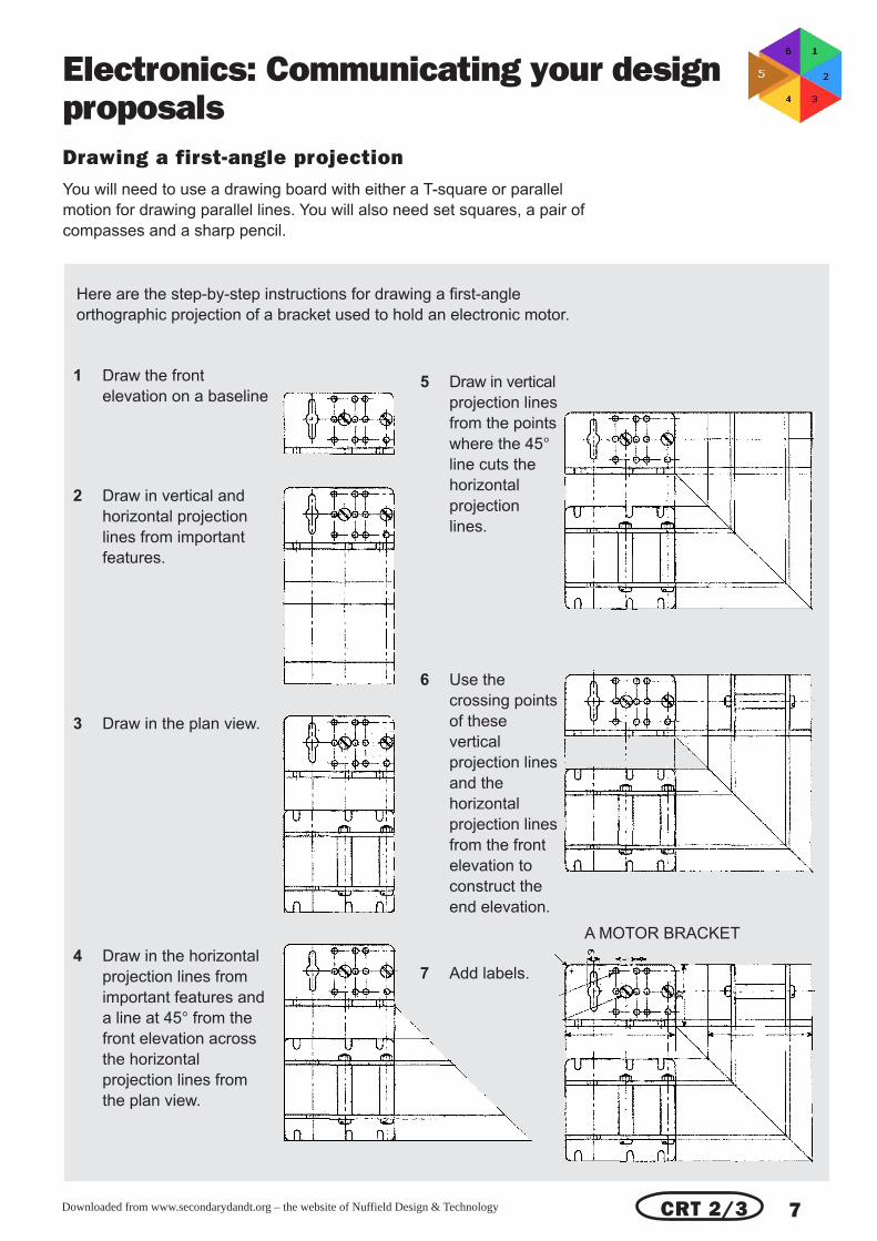
Electronics: Communicating your designproposalsDrawing a first-angle projectionYou will need to use a drawing board with either a T-square or parallel
motion for drawing parallel lines. You will also need set squares, a pair of
compasses and a sharp pencil.
Here are the step-by-step instructions for drawing a first-angle
orthographic projection of a bracket used to hold an electronic motor.
1 Draw the front
elevation on a baseline
2 Draw in vertical and
horizontal projection
lines from important
features.
3 Draw in the plan view.
4 Draw in the horizontal
projection lines from
important features and
a line at 45° from the
front elevation across
the horizontal
projection lines from
the plan view.
5 Draw in vertical
projection lines
from the points
where the 45°line cuts the
horizontal
projection
lines.
6 Use the
crossing points
of these
vertical
projection lines
and the
horizontal
projection lines
from the front
elevation to
construct the
end elevation.
7 Add labels.
A MOTOR BRACKET
CRT 2/3
Downloaded from www.secondarydandt.org – the website of Nuffield Design & Technology 8
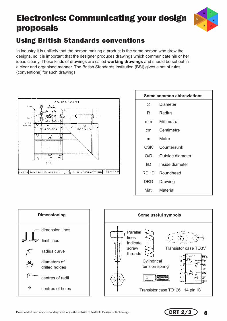
Electronics: Communicating your designproposalsUsing British Standards conventionsIn industry it is unlikely that the person making a product is the same person who drew the
designs, so it is important that the designer produces drawings which communicate his or her
ideas clearly. These kinds of drawings are called working drawings and should be set out in
a clear and organised manner. The British Standards Institution (BSI) gives a set of rules
(conventions) for such drawings
Some useful symbols
Parallel
lines
indicate
screw Transistor case TO3V
threads
Cylindrical
tension spring
Transistor case TO126 14 pin IC
Dimensioning
dimension lines
limit lines
radius curve
diameters of
drilled holdes
centres of radii
centres of holes
Some common abbreviations
∅ Diameter
R Radius
mm Millimetre
cm Centimetre
m Metre
CSK Countersunk
O/D Outside diameter
I/D Inside diameter
RDHD Roundhead
DRG Drawing
Matl Material
CRT 2/3

Downloaded from www.secondarydandt.org – the website of Nuffield Design & Technology 9
Electronics: Communicating your designproposals
CRT2/3
Sectional viewsMost electronic products are enclosed in some sort
of container. It is important that the layout of the
container and the way in which circuit boards and
components fit is clear. You can use a sectional
view to show this. In a sectional view an imaginary
cut is made through the object, you then remove
one half and draw what you can now see. Any
surfaces which are ‘cut’ are cross-hatched with
lines drawn at 45°. These lines change direction
between different pieces of material.
Downloaded from www.secondarydandt.org – the website of Nuffield Design & Technology 10
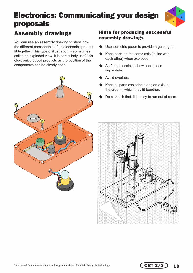
Electronics: Communicating your designproposalsAssembly drawingsYou can use an assembly drawing to show how
the different components of an electronics product
fit together. This type of illustration is sometimes
called an exploded view. It is particularly useful for
electronics-based products as the position of the
components can be clearly seen.
Hints for producing successfulassembly drawings
◆ Use isometric paper to provide a guide grid.
◆ Keep parts on the same axis (in line with
each other) when exploded.
◆ As far as possible, show each piece
separately.
◆ Avoid overlaps.
◆ Keep all parts exploded along an axis in
the order in which they fit together.
◆ Do a sketch first. It is easy to run out of room.
CRT 2/3

Downloaded from www.secondarydandt.org – the website of Nuffield Design & Technology 11
Electronics: Communicating your designproposalsProcess specificationWhen you make a product, you need to think
about the order of work. The picture below shows
a container for an electronic product made by
vacuum forming. The base fits inside the plastic
moulding and is held in place by four screws which
pass through the cover and into threaded holes in
the edge of the base. The vacuum forming has to
be done first as the base must be made to fit
inside.
In other products various sub-assemblies may
have to be made and tested before they can be
tried together. A remote control vehicle that follows
a white line has a drive system which requires an
electric motor and gearbox. It would be sensible to
make up the motor and gearbox assembly first and
make sure that it works before fitting it into the
vehicle and adding the control circuit.
The same idea can be applied to electronic
circuits. The components which need protection
from heat, such as transistors and ICs, should be
fitted last so that they are not subject to heat when
other components are being fitted. In complex
circuits, try to build these as subsections which
can be made and tested before being joined to
other parts of the circuit. If you have a design
which uses a sensing circuit, this can be built and
tested for an output before fitting it to the process
part of the circuit. Similarly, an output section,
which might involve a power transistor, relay and a
motor, can be tested before fitting it to the process
part. This method of construction makes fault
finding easier as any faults will be limited to a
small part of the circuit.
In industry, the designer will usually specify the
order of construction to the person who makes the
product. In your work in school you can use flow
charts to plan the order of your work.
CRT 2/3

Downloaded from www.secondarydandt.org – the website of Nuffield Design & Technology 12
Electronics: Communicating your designproposalsUsing jigs and fixturesYou can use a jig to help you to carry out difficult or tedious making operations. If you have to make a
number of identical parts or work very accurately, then a Jig will help. Here are two examples To make
24 of the part shown here, each with four holes in exactly the right places, is both tedious and difficult.
The drilling jig makes this a simple operation.
Producing a coil for a radio aerial or for
a solenoid takes a long time and
requires accuracy, so a coil-winding jig
like the one shown here is particularly
useful. If you design and make this
yourself, then this work can count
towards your examination grade.
CRT 2/3

Downloaded from www.secondarydandt.org – the website of Nuffield Design & Technology 13
Electronics: Communicating your designproposalsCommunicating the circuit
Circuit diagramsA circuit diagram for an electronic product shows the order in which the components are
connected together. This sort of diagram is drawn with space between each component so that
the connections can be seen clearly. Standard symbols are used to show the components and
how the connections are made. When you draw a circuit diagram, make a free-hand sketch first
and then draw the diagram neatly. You should use the standard symbols, some of which are
shown below.
CRT 2/3
Downloaded from www.secondarydandt.org – the website of Nuffield Design & Technology 14
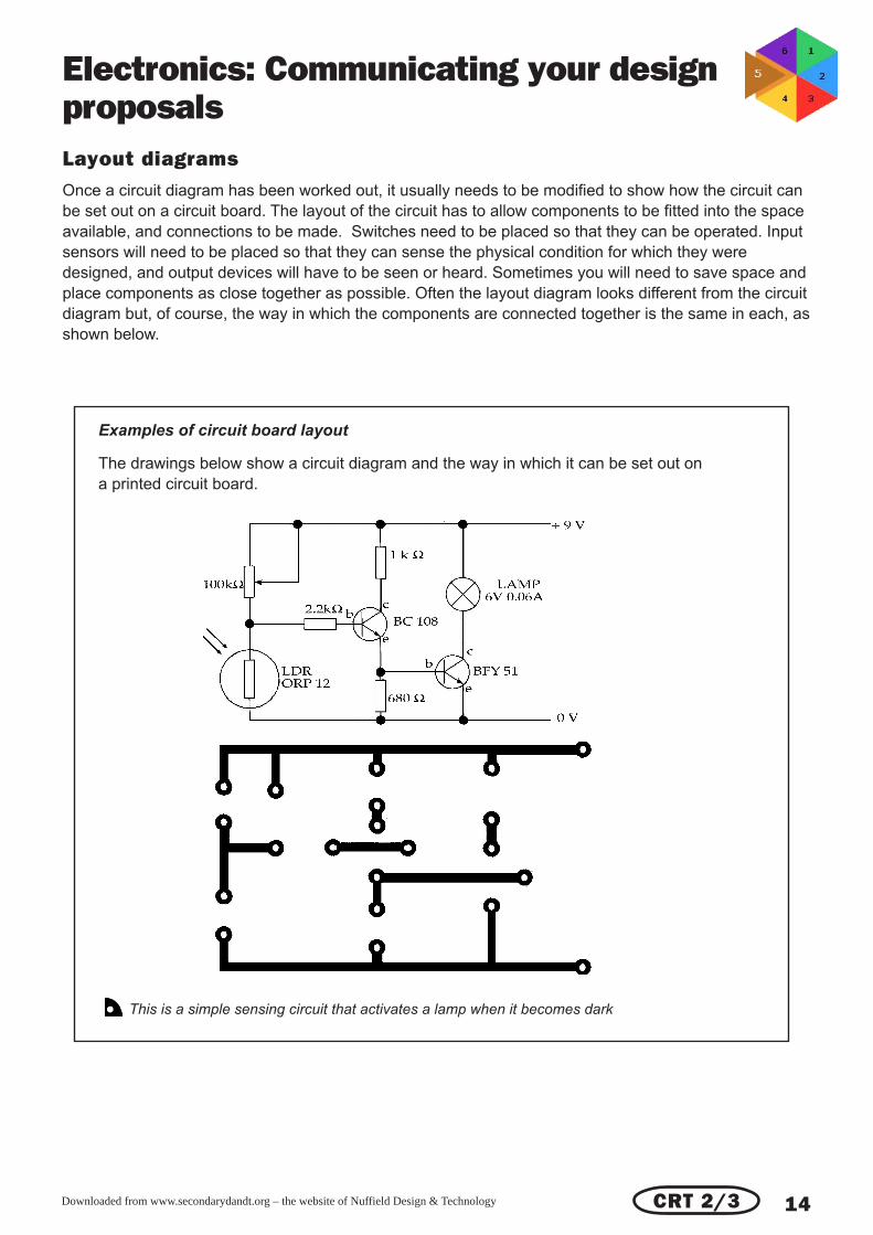
Electronics: Communicating your designproposalsLayout diagramsOnce a circuit diagram has been worked out, it usually needs to be modified to show how the circuit can
be set out on a circuit board. The layout of the circuit has to allow components to be fitted into the space
available, and connections to be made. Switches need to be placed so that they can be operated. Input
sensors will need to be placed so that they can sense the physical condition for which they were
designed, and output devices will have to be seen or heard. Sometimes you will need to save space and
place components as close together as possible. Often the layout diagram looks different from the circuit
diagram but, of course, the way in which the components are connected together is the same in each, as
shown below.
CRT 2/3
This is a simple sensing circuit that activates a lamp when it becomes dark
Examples of circuit board layout
The drawings below show a circuit diagram and the way in which it can be set out on
a printed circuit board.

Downloaded from www.secondarydandt.org – the website of Nuffield Design & Technology 15
Electronics: Communicating your designproposalsCommunicating to the user
Many products are provided with an instruction
book or user guide. These are used to describe
simple operations, such as how to fit the various
blades and beaters to a food processor, as well as
complicated procedures, such as how to assemble
an item of ‘flatpack’ furniture.
Some of the electronic products which you design
and make will need user guides. If the product is
simple, then the guide might just show how to
replace batteries, indicator lamps or fuses. More
complex products will require detailed instructions.
For example, sensing instruments would need
instructions on how to set up and connect the
sensors, security devices would need a user guide
to show how the sensors should be installed and
how the device should be set and returned to a
‘safe’ condition. Control systems would need a
user guide on setting up, testing and, if
programmable, how the control sequence can be
modified. A user guide may also contain a fault
finding chart.
Producing a user guide is as much a design task
as the making of a three-dimensional product and
is an area where you can use your graphic skills to
good effect. Use the following guidelines when
producing a user guide.
◆ Keep body text to a minimum.
◆ Avoid over-technical language.
◆ Use illustrations plus annotations for the
naming of parts.
◆ Use step-by-step drawings as instructions.
◆ Use graphics software and desktop publishing
software for really professional-looking results.
◆ If you have access to word processing
software, only use this for the text and leave
space for illustrations which you can add to the
print-out by hand.
When you have produced a guide, ask one of your
friends to take a user trip and read it through to
see that it makes sense!
CRT 4
Downloaded from www.secondarydandt.org – the website of Nuffield Design & Technology 16
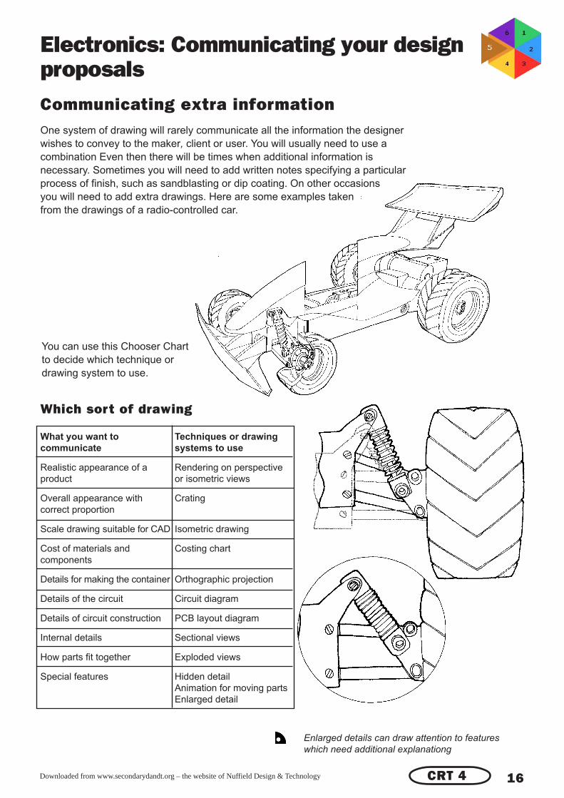
Electronics: Communicating your designproposalsCommunicating extra informationOne system of drawing will rarely communicate all the information the designer
wishes to convey to the maker, client or user. You will usually need to use a
combination Even then there will be times when additional information is
necessary. Sometimes you will need to add written notes specifying a particular
process of finish, such as sandblasting or dip coating. On other occasions
you will need to add extra drawings. Here are some examples taken
from the drawings of a radio-controlled car.
Enlarged details can draw attention to features
which need additional explanationg
Which sort of drawing
What you want to Techniques or drawing
communicate systems to use
Realistic appearance of a Rendering on perspective
product or isometric views
Overall appearance with Crating
correct proportion
Scale drawing suitable for CAD Isometric drawing
Cost of materials and Costing chart
components
Details for making the container Orthographic projection
Details of the circuit Circuit diagram
Details of circuit construction PCB layout diagram
Internal details Sectional views
How parts fit together Exploded views
Special features Hidden detail
Animation for moving parts
Enlarged detail
You can use this Chooser Chart
to decide which technique or
drawing system to use.
CRT 4