electromagnetic scattering analysis and design …etd.lib.metu.edu.tr/upload/12610527/index.pdf ·...
TRANSCRIPT

i
ELECTROMAGNETIC SCATTERING ANALYSIS AND DESIGN OF SANDWICH TYPE RADOMES
A THESIS SUBMITTED TO THE GRADUATE SCHOOL OF NATURAL AND APPLIED SCIENCES
OF MIDDLE EAST TECHNICAL UNIVERSITY
BY
MEHMET MURAT ŞEREFOĞLU
IN PARTIAL FULLFILLMENT OF THE REQUIREMENTS FOR
THE DEGREE OF MASTER OF SCIENCE IN
ELECTRICAL AND ELECTRONICS ENGINEERING
APRIL 2009

ii
Approval of the thesis:
ELECTROMAGNETIC SCATTERING ANALYSIS AND DESIGN OF SANDWICH TYPE RADOMES
submitted by MEHMET MURAT ŞEREFOĞLU in partial fulfillment of the
requirements for the degree of Master of Science in Electrical and
Electronics Engineering Department, Middle East Technical University
by,
Prof. Dr. Canan Özgen
Dean, Graduate School of Natural and Applied Sciences Prof. Dr. İsmet Erkmen
Head of Department, Electrical and Electronics Engineering Prof. Dr. Gülbin Dural
Supervisor, Electrical and Electronics Engineering Dept., METU
Examining Committee Members:
Prof. Dr. Altunkan Hızal
Electrical and Electronics Engineering Dept., METU Prof. Dr. Gülbin Dural
Electrical and Electronics Engineering Dept., METU Prof. Dr. Nilgün Günalp
Electrical and Electronics Engineering Dept., METU Prof. Dr. Canan Toker
Electrical and Electronics Engineering Dept., METU Celal Dudak
Msc, TÜBİTAK
Date:

iii
I hereby declare that all information in this document has been obtained
and presented in accordance with academic rules and ethical conduct. I
also declare that, as required by these rules and conduct, I have fully cited
and referenced all material and results that are not original to this work.
Name, Last name :Mehmet Murat ŞEREFOĞLU
Signature :
iv
ABSTRACT
ELECTROMAGNETIC SCATTERING ANALYSIS
AND DESIGN OF SANDWICH TYPE RADOMES
Şerefoğlu, Mehmet Murat
M. Sc., Department of Electrical and Electronics Engineering
Supervisor: Prof. Dr. Gülbin Dural
April 2009, 103 pages
In this thesis work, importance of radome structures for antenna systems is
emphasized. Structural and electromagnetic requirements of various types of
radome structures are analyzed and specific properties are given.
Electromagnetic scattering analysis of sandwich type radome seams has been
done. Total antenna system far electromagnetic field expression, which is the
combination of original antenna far electromagnetic field and the scattered
electromagnetic field of the framework of the sandwich radome structure has
been found and simulated. To enhance electromagnetic transparency of
sandwich type radomes two sandwich radome design methods are proposed
which are expressed as Geometrical Randomization and Tuning the Seams.
Electromagnetic scattering level minimizations advanced by these design
methods are presented with related simulations.

v
Keywords: Scattering Analysis of Sandwich Radomes, Tuning the Seams,
Geometric Randomization, Quasi-Random Designed Radome Geometry,

vi
ÖZ
SANDVİÇ TİPİ ANTEN KAPORTALARININ
ELEKTROMANYETİK SAÇILIM ANALİZİ VE
TASARIMI
Şerefoğlu, Mehmet Murat
Yüksek Lisans, Elektrik-Elektronik Mühendisliği Bölümü
Tez Yöneticisi: Prof. Dr. Gülbin Dural
Nisan 2009, 103 sayfa
Bu tez çalışmasında anten kaportası yapılarının anten sistemleri için önemine
vurgu yapılmıştır. Çeşitli anten kaportalarının yapısal ve elektromanyetik
gereksinimleri analiz edilerek spesifik özellikleri verilmiştir. Sandviç tipi anten
kaportalarının elektromanyetik saçılım analizi yapılmıştır. Orijinal anten uzak
elektromanyetik dalgasının ve sandviç anten kaportası iskeletinden saçılan
elektromanyetik dalganın kombinasyonundan oluşan toplam anten sistemi uzak
elektromanyetik dalgası bulunarak benzetimi yapılmıştır. Sandviç anten
kaportalarının elektromanyetik geçirgenliğini artırabilmek için Geometrik
Rastlantısallık ve Eklem Yeri Dalga Ayarlama şeklinde ifade edilen iki tasarım
yöntemi önerilmiştir. Bu tasarım yöntemleriyle kazanılan elektromanyetik
saçılım seviyesindeki azalma ilgili benzetimlerle sunulmuştur.

vii
Anahtar Kelimeler: Sandviç Anten Kaportalarının Saçılım Analizi, Eklem
Yerlerinin Dalga Uyumu, Geometrik Rasgele Dağılım, Rasgele Tasarlanmış
Anten Kaportası Geometrisi

viii
To My Dear Family

ix
ACKNOWLEDGEMENTS
I would like to express my deepest gratitude to my supervisor Prof. Dr. Gülbin
Dural for her encouragements, guidance, advice, criticism and insight
throughout my thesis work.
I would like to thank to Prof. Dr. Altunkan HIZAL for his encouragement and
guidance about my thesis work.
I would also like to express my profound appreciation to my dear family for
their continuous support, motivation and patience throughout this thesis work
as always in my life.
I would like to thank ASELSAN Inc. for their continuous support during my
graduate study.
I would also like to thank Turkish Scientific and Technological Research
Council (TÜBİTAK) for their financial assistance during my graduate study.
I would like to forward my appreciation to all my friends and colleagues who
contributed to my thesis work with their continuous encouragement.

x
TABLE OF CONTENTS
ABSTRACT......................................................................................................iv
ÖZ......................................................................................................................vi
ACKNOWLEDGEMENTS.............................................................................ix
TABLE OF CONTENTS..................................................................................x
LIST OF TABLES ..........................................................................................xii
LIST OF FIGURES .......................................................................................xiii
LIST OF ABBREVIATIONS ......................................................................xvii
CHAPTERS
1. INTRODUCTION.........................................................................................1
2. RADOMES ....................................................................................................4
2.1 General Information ..........................................................................4
2.2 Necessity of Radomes.......................................................................5
2.3 Requirements of Radomes ................................................................6
2.3.1 Mechanical Requirements of Radomes......................................7
2.3.2 Electromagnetic Requirements of Radomes ..............................9
2.4 Radome Types.................................................................................17
2.4.1 Solid Laminate Radomes .........................................................17
2.4.2 Dielectric Space Frame Radomes ............................................19
2.4.3 Metal Space Frame Radomes...................................................20
2.4.4 Air Pressurised Radomes .........................................................25
2.5 Sandwich Type Radomes................................................................27
2.5.1 Features of Sandwich Type Radomes ......................................28

xi
2.5.2 Advantages of Sandwich Type Radomes.................................31
2.5.3 Disadvantages of Sandwich Type Radomes ............................32
2.5.4 Importance of Framework Structures in Sandwich Type
Radomes............................................................................................32
2.5.5 Structural and Electromagnetic Comparison of Different
Sandwich Radome Framework Geometries......................................33
3. ELECTROMAGNETIC SCATTERING ANALYSIS OF SEAMS IN
SANDWICH TYPE RADOMES ...................................................................37
3.1 General Information ........................................................................37
3.2 Scattering Analysis of Radome Seams ...........................................38
3.3 Total Far Field Expression of Antenna and Arbitrary Distributed
Sandwich Radome Seams .....................................................................46
3.4 Simulations Based on the Analysis .................................................56
4. ENHANCING ELECTROMAGNETIC TRANSPARENCY OF
SANDWICH TYPE RADOMES ...................................................................73
4.1 Factors Effecting Electromagnetic Performance of the Structure...73
4.2 Importance of the Distance of the Seam Structure to the Antenna
Aperture ................................................................................................74
4.3 Enhancing Electromagnetic Transparency by Quasi-Random
Geometric Distribution of Seams..........................................................79
4.4 Electromagnetic Transparency Enhancement by Tuning the Seams
in Sandwich Type Radomes..................................................................86
4.4.1 Tuning the Seams in Sandwich Type Radomes.......................86
4.4.2 Effect of Tuning the Seams in Sandwich Type Radomes........87
5. CONCLUSIONS .........................................................................................94
REFERENCES................................................................................................98
APPENDIX ....................................................................................................101

xii
LIST OF TABLES
Table 1- Structural Comparison of Metal Space Frame Radomes and Dielectric
Space Frame Radomes [2]............................................................................24
Table 2- Structural Comparison of Quasi Random Sandwich Radome
Geometry and Orange-Peel Sandwich Radome Geometry ..........................36

xiii
LIST OF FIGURES
Figure 1- Preparation of a radome panel for transportation [5] ..........................8
Figure 2-Beginning, intermediate and final installation of a radome
structure [6] ....................................................................................................9
Figure 3 - Induced Field Ratio [9].....................................................................11
Figure 4- Evaluating Hydrophobicity by Measuring the Contact Angle of the
Water Droplet on the Surface [10] ...............................................................14
Figure 5- Hydrophobic and Non-Hydrophobic Material Responses to Water .15
Figure 6- Effect of Hydrophobic Coating on Transmission Loss [10] .............16
Figure 7 - Solid Laminate Radome for Shipboard Data Communications [3] .17
Figure 8 - 3.05 m Diameter Solid Laminate Radome for MK-86 Gun Fire
Control System [3] .......................................................................................18
Figure 9 - Dielectric Space Frame Radome [2] ................................................19
Figure 10- 14.1 m Diameter Metal Space Frame Radome [3].........................21
Figure 11- Beginning, Intermediate and Final Installations of Air Pressurised
Radome [11] .................................................................................................26
Figure 12 -Sandwich Type Radome with Large Access Doors [3] ..................27
Figure 13- Sandwich Radome Types [13] ........................................................28
Figure 14- 3D Glass Material Used in Core Part of Type-A Sandwich
Radomes [19] ...............................................................................................29
Figure 15- Honeycomb Core Materials Used in Type-A Sandwich
Radomes [19] ...............................................................................................30
Figure 16- Sandwich Radome Panels and Framework Geometry ....................31
Figure 17- Typical Quasi Random Sandwich Radome Geometry....................34
Figure 18 – Typical Orange Peel Sandwich Radome Geometry ......................34
Figure 19 - Scattering Geometry of the Analysis..............................................40

xiv
Figure 20- Far E-Field Characteristics of Antenna and Different Sandwich
Radome Seam Distributions.........................................................................58
Figure 21- Design of Pyramidal Horn Antenna ................................................59
Figure 22 – 3D Polar Plot of the Horn Antenna E-Field Pattern ......................60
Figure 23 - 3D Rectangular Plot of the Antenna E-Field Pattern .....................61
Figure 24- 2D Total E-Field Radiation Characteristics of the Antenna on
Principal Planes ............................................................................................61
Figure 25- Placement of 4,8 λ Length and 0,2 λ Diameter Horizontal
Sandwich Radome Seam at 6λ Distance to the Horn Antenna....................63
Figure 26 - 3D Polar Plot of the Total E-Field Pattern of the 4,8 λ Length and
0,2 λ Diameter Horizontal Sandwich Radome Seam Placed at 6λ Distance
to the Antenna ..............................................................................................64
Figure 27 - 3D Rectangular Plot E-Field Pattern of the 4,8 λ Length and 0,2 λ
Diameter Horizontal Sandwich Radome Seam Placed at 6λ Distance to the
Antenna ........................................................................................................65
Figure 28 - 2D Total E-Field Radiation Characteristics of 4,8 λ Length and
0,2 λ Diameter Horizontal Sandwich Radome Seam Placed at 6λ Distance
to the Antenna ..............................................................................................65
Figure 29- Placement of 4,8 λ Length and 0,2 λ Diameter Perpendicular
Sandwich Radome Seam at 6λ Distance to the Antenna.............................66
Figure 30 - 3D Polar Plot of the E-Field Pattern with 4,8 λ Length and 0,2 λ
Diameter Perpendicular Sandwich Radome Seam in the Near Field of the
Antenna ........................................................................................................67
Figure 31 - 3D Rectangular Plot of the E-Field Pattern of the 4,8 λ Length and
0,2 λ Diameter Perpendicular Sandwich Radome Seam and the Antenna .68
Figure 32- 2D Total E-Field Radiation Characteristics of 4,8 λ Length and 0,2
λ Diameter Perpendicular Sandwich Radome Seam Placed at 6λ Distance
to the Antenna ..............................................................................................68
Figure 33- Multi Numbered Distribution of 4,8 λ Length and 0,2 λ Diameter
Sandwich Radome Seams Placed at 6λ Distance to the Antenna................70

xv
Figure 34 - 3D Polar Plot of the E-Field of the Distributed 4,8 λ Length and
0,2 λ Diameter Sandwich Radome Seams Placed at 6λ Distance to the
Antenna ........................................................................................................71
Figure 35 - 2D Total E-Field Radiation Characteristics of Distributed 4,8 λ
Length and 0,2 λ Diameter Sandwich Radome Seams Placed at
6λ Distance to the Antenna..........................................................................71
Figure 36 - 4,8 λ Length and 0,2 λ Diameter Sandwich Radome Seam Placed
at 3λ Distance to the Aperture ....................................................................75
Figure 37 - 4,8 λ Length and 0,2 λ Diameter Sandwich Radome Seam Placed
at 10.7λ Distance to the Aperture................................................................75
Figure 38 - 3D Cartesian Plot of the Total E-Field Pattern of 3λ Distant 4,8 λ
Length and 0,2 λ Diameter Sandwich Radome Seam ................................77
Figure 39 - 3D Cartesian Plot of the Total E-Field Pattern of10.7λ Distant 4,8
λ Length and 0,2 λ Diameter Sandwich Radome Seam............................77
Figure 40 - Polar Plot of the Total E-Field Pattern of 3λ Distant 4,8 λ Length
and 0,2 λ Diameter Sandwich Radome Seam.............................................78
Figure 41 - Polar Plot of the Total E-Field Pattern of 10.7λ Distant 4,8 λ
Length and 0,2 λ Diameter Sandwich Radome Seam ................................78
Figure 42 – 18.9 Meter Diameter Sandwich Radome Panels and Panel
Framework Geometry [3].............................................................................80
Figure 43 – Orange-Peel Radome Framework Design with 2,8 λ Length and
0,2 λ Diameter 12 Seams Placed at 6λ Distance to the Antenna ...............81
Figure 44 - 3D Polar Plot of Total E-Field Pattern of Orange-Peel Type
Designed Sandwich Radome Framework with 2,8 λ Length and 0,2 λ
Diameter 12 Seams Placed at 6λ Distance to the Antenna..........................82
Figure 45 - 3D Rectangular Plot of the E-Field Pattern Characteristics of
Orange-Peel Type Designed Sandwich Radome Framework with 2,8 λ
Length and 0,2 λ Diameter 12 Seams Placed at 6λ to the Antenna ........83
Figure 46 – Randomized Distribution of 2,8 λ Length and 0,2 λ Diameter 12
Seams Placed at Approximately 6λ Distance In Front of the Antenna .......84

xvi
Figure 47 - 3D Polar E-Field Pattern of Random Distributed 2,8 λ Length and
0,2 λ Diameter 12 Seams Placed at Approximately 6λ Distance In Front of
the Antenna...................................................................................................85
Figure 48- 3D Rectangular Total E-Field Pattern of Random Distributed 2,8 λ
Length and 0,2 λ Diameter 12 Seams Placed at Approximately 6λ
Distance In Front of the Antenna .................................................................85
Figure 49 – Horizontal Silicon Dioxide Cylinder Seam with 4,8 λ Length and
0,47λ Diameter Placed at 5λ Distance to the Horn Antenna ....................88
Figure 50 - 3D Polar Total E-Field of the Horizontal Silicon Dioxide Seam
with 4,8 λ Length and 0,47λ Diameter Placed at 5λ Distance to the Horn
Antenna ........................................................................................................88
Figure 51 - 3D Rectangular Total E-Field of the Horizontal Silicon Dioxide
Seam with 4,8 λ Length and 0,47λ Diameter Placed at 5λ Distance to the
Horn Antenna ...............................................................................................89
Figure 52 - 2D Total E-Field of the Horizontal Silicon Dioxide Seam with 4,8
λ Length and 0,47λ Diameter Placed at 5λ Distance to the Horn
Antenna ........................................................................................................89
Figure 53 - Tuning Mechanism of the Silicon Dioxide Dielectric Seam with
Perfect Electric Conductors..........................................................................91
Figure 54 -3D Polar Plot of the Total E-Field Pattern of the Tuned Seam with
4,8 λ Length and 0,47λ Diameter Placed at 5λ Distance to the Horn
Antenna ........................................................................................................92
Figure 55 - 3D Rectangular Plot of the E-Field Pattern of the Tuned Seam with
4,8 λ Length and 0,47λ Diameter Placed at 5λ Distance to the Horn
Antenna ........................................................................................................92
Figure 56 - 2D Total E-Field Radiation Characteristics of Tuned Sandwich
Radome Seam with 4,8 λ Length and 0,47λ Diameter Placed at 5λ
Distance to the Horn Antenna ......................................................................93
xvii
LIST OF ABBREVIATIONS
DSF : Dielectric Space Frame
FRP : Fiberglass Reinforced Plastic
MSF : Metal Space Frame
SLR : Solid Laminate Radome
SRS : Sandwich Radome Seam
TE : Transverse Electric
TM : Transverse Magnetic
VSWR : Voltage Standing Wave Ratio

1
CHAPTER 1
INTRODUCTION
Typically, large antenna systems are covered with radomes in order to
protect them from harsh weather conditions and to enable them to operate
continuously without loss of precision. Radomes enhance performance of
operation of the antenna systems in harsh atmospheric conditions such as
intense wind, sand, rain, corrosion etc. They are also very crucial for
decreasing life time cost of large antenna systems. There are various types
of radome structures for specific purposes of the antenna systems.
Depending on the size of the antennas the radomes are usually assembled
from many panels which are connected together forming joints or seams. In
high performance discrete narrow bandwidth applications, the panels are
usually Type-A sandwiches that are optimized for minimum transmission
loss over moderately narrow bandwidths. However, the physical dimensions
of the panel framework, in other words, radome seams are usually
determined by structural considerations, such as maximum wind speed or
other resultant stresses they have to sustain. However, without
electromagnetic consideration, the framework degrades the total system
performance by introducing high scattering levels. Therefore, it is very
crucial for the whole system to minimize this scattering effect due to the
framework while protecting the antenna system.

2
In this thesis work, requirements of radomes are expressed. Various types of
radome structures and their specific properties are presented. Detailed
information about Sandwich Radomes is expressed. Electromagnetic
scattering analysis of sandwich type radomes is done. To enhance
electromagnetic transparency of radome seams in the sandwich radomes,
two different design methods are proposed which are named as Geometrical
Randomization and Tuning the Seams.
In Chapter 2, general information about radomes including definition, the
purpose of usage and necessity is given. Mechanical and electromagnetic
requirements of radomes are investigated. Factors affecting the
electromagnetic performance of radomes such as insertion loss and
scattering loss are defined. Importance of Hydrophobic coating on the
outermost side of the radome panel structure is emphasized. Information
about different radome types including antenna systems they cover, the
operational frequency band, general size of the structures and cost
information is given. Detailed information including advantages and
disadvantages of Sandwich Radomes is expressed. Electromagnetic
importance of the framework geometry in Sandwich Radomes is
investigated. Finally, structural and electromagnetic properties of two
common Sandwich Radome geometries are discussed.
Chapter 3 is devoted to electromagnetic scattering analysis of Sandwich
Radomes. The analysis is applicable to all type of antennas with the
condition of knowledge of near and far electromagnetic field equations of
the antenna inside. Pyramidal horn type of antenna is used as a case study
for the analysis. Scattering by arbitrarily distributed radome seams is
formulated. Total far electromagnetic fields including antenna far
electromagnetic fields and scattering electromagnetic fields from arbitrarily

3
distributed radome seams are formulated. Simulations based on the analysis
are performed and the effect of scattering is visualized.
In Chapter 4, the ways of enhancing electromagnetic transparency of the
Sandwich Radome Seams (SRS) are investigated. Two different design
methods are proposed to enhance transparency. They are named as
Geometrical Randomization and Tuning the Seams. Both methods are
expressed in detail, and the effect of transparency enhancement by the
methods is visualized by related simulations.
Chapter 5 is devoted to the conclusion of this thesis work. This chapter
summarizes all the work done in this thesis work. Finally, possible future
work areas about sandwich radomes are mentioned considering
constructional and electromagnetic responses of different materials which
constitute the sandwich radome panels and the framework.

4
CHAPTER 2
RADOMES
2.1 General Information
The radome is a structural, weatherproof enclosure that protects a
microwave or radar antenna for radar, telemetry, tracking, communications,
surveillance, and radio astronomic applications [1,2]. The name “radome” is
a contraction of the words “radar” and “dome” [1]. Generally, the radomes
are used for protecting the antenna surfaces from harsh environmental
conditions such as wind, rain, snow, ice, blowing sand, fungus, corrosion
and ultraviolet rays etc. Also, they can be used for protecting nearby
personnel from being accidentally struck by quickly-rotating antennas [2].
Moreover they can be used for protecting and/or concealing antenna
electronic equipment from public view especially for secret security
applications [2,3].
In this chapter necessity of radome is emphasized. Requirements of radomes
are investigated. Different radome structures are revealed and their special
properties are given. Sandwich Type Radomes are defined and their detailed
properties are expressed including advantages and disadvantages.
Importance of the framework geometry for the Sandwich Radomes is

5
discussed. Finally, structural and electromagnetic comparisons of two
common framework geometries of Sandwich Radomes are expressed.
2.2 Necessity of Radomes
Radome should be constructed of the material such that it protects the
antenna from harsh weather conditions while minimally attenuating the
electromagnetic signal transmitted or received by the antenna. In other
words, the radome should be physically strong for protection and
transparent to electromagnetic waves to maintain the antenna stable
operation.
It is important to maintain antenna stable operation while protecting the
antenna from harsh weather conditions. A radome is often used to prevent
ice and freezing rain from accumulating directly onto the metal surface of
the antennas. Especially for stationary antennas, excessive amounts of ice
can de-tune the antenna to the point where its impedance at the input
frequency rises drastically, causing voltage standing wave ratio (VSWR) to
rise as well [1]. This reflected power goes back to the transmitter, where it
can cause overheating. A foldback circuit activates to prevent this.
However, it causes the station's output power to drop dramatically, that
leads reducing its range [1].
Wind is an important factor for both stationary and spinning radar antennas.
High intense wind may distort the shape and the pointing of direction of the
antenna or it may cause spinning irregularities for a spinning antenna.
Therefore, using radome increases pointing and tracking accuracy [3].

6
Rain is an important factor for high frequency radar applications. Especially
above 5 GHz frequency transmission loss effect increases very rapidly. The
effect leads to 10 dB transmission loss above 30 GHz. So it is important to
prevent this effect for high performance antenna applications by using a
radome which has hydrophobic coating feature. Detailed information about
hydrophobic coating feature of radomes is given at the section 2.3.2 named
as “Electromagnetic Requirements of Radomes”.
Economically, radomes are proven to be very effective when considering
life cycle costs of the antenna systems. Since the antenna system is in a
protected environment, maintenance costs are held to a minimum. The
structural requirements of the antenna are less stringent, resulting in reduced
fabrication and installation costs plus the use of smaller positioning motors
[2].
As a facility, radomes provide a benign environment for any electronics and
personnel that must be located near the antenna for designing or repairing
applications. This is especially significant in harsh weather conditions such
as temperature extremes, blowing sand or dirt, salt spray, and freezing rain
[2].
Therefore it is very crucial to have radomes for high performance large
radar antenna systems.
2.3 Requirements of Radomes
Radomes are important parts of high frequency antenna systems. Radomes
should protect antenna systems from harsh weather conditions. The design
of the radome should be such that while protecting the system it should

7
minimally attenuate the electromagnetic signal received or transmitted by
the antenna inside. We can investigate requirements of radomes in two
different parts such as “mechanical requirements of radomes” and
“electromagnetic requirements of radomes”.
2.3.1 Mechanical Requirements of Radomes
While designing radomes it is important to decide its physical, in other
words, mechanical properties. Radomes are used in different applications,
such as naval applications, aircraft applications and ground applications.
The place where the antenna system is constructed has to be considered and
to be concentrated with its own properties at first. This consideration should
include snow and rain loading, wind / gust rating, temperature of the place
where the system operates, installation, transportation and repairing costs of
the system.
Depending on the strength of the weather conditions on the antenna system
the structure manufacturing changes. For example, generally radomes are
designed to operate with wind speeds up to 60 m/s (134 mph), and snow or
ice loading up to 235-kg/m2 (50-lb/ft2) [4]. For an application which has
higher wind speed or snow loading requirements the weight ratio of the
structure has to be increased. However, enhancing structural properties of
the radome may degrade electromagnetic performance of the radome if it is
not properly designed.
Moreover, the nearby temperature is also an important consideration. For
example, if the chosen radome is going to be used with a large radar antenna
system, there should be nearby personnel to install and repair the systems.
Even for the electronic equipments of the antenna there are temperature

8
requirements. If the antenna system is built in a cold climate, thermal
insulation properties of the radome structure has higher importance.
The antenna system size may change between 1.8 m and 60 meters in
diameter. To cover large antenna systems, radomes are composed of many
panels. These panels are manufactured and then transported to the place of
the antenna system and installed there (Figure 1 and 2). For transportation
point of view the panel size is an important issue. In a typical design, panel
dimensions are held to be less than 225 cm. This permits use of a standard
ISO shipping container [4]. If the size increases transportation cost
increases. However, these panels have to be installed at the antenna station
so if the size of the radome panels decreases this time installation cost
increases. So there should be an optimum decision for the radome panel size
when considering cost of the radome structure.
Figure 1- Preparation of a radome panel for transportation [5]
9
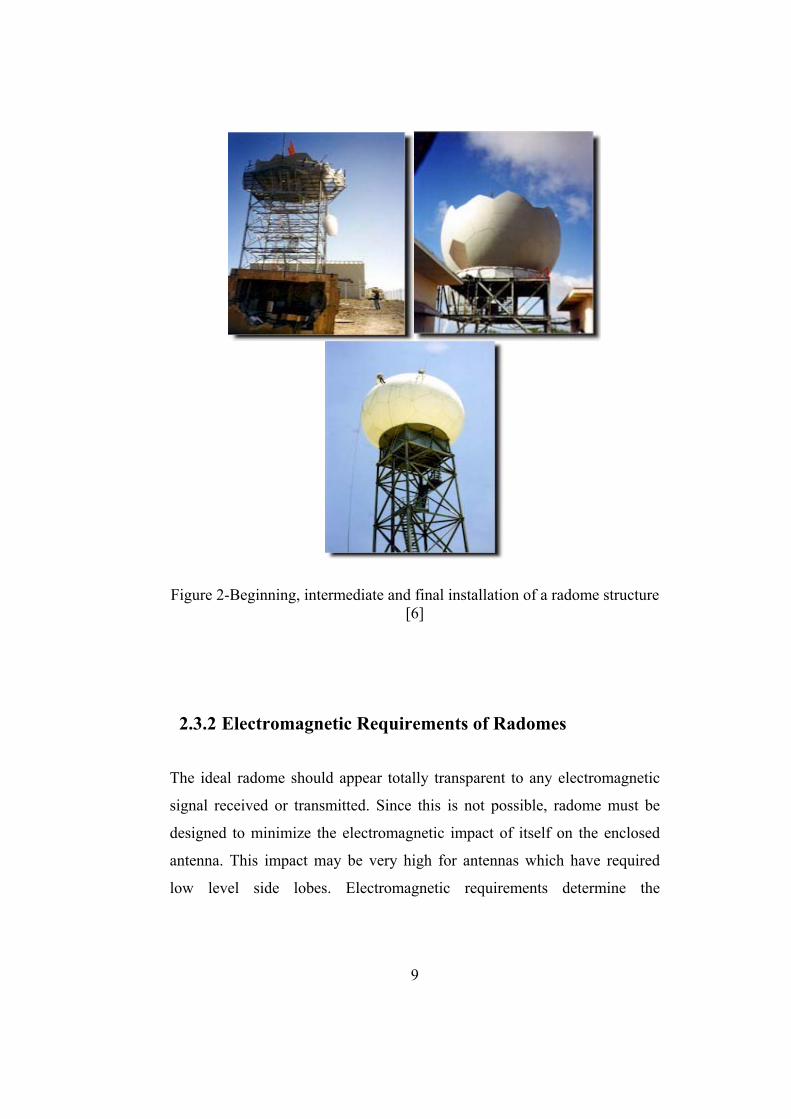
Figure 2-Beginning, intermediate and final installation of a radome structure [6]
2.3.2 Electromagnetic Requirements of Radomes
The ideal radome should appear totally transparent to any electromagnetic
signal received or transmitted. Since this is not possible, radome must be
designed to minimize the electromagnetic impact of itself on the enclosed
antenna. This impact may be very high for antennas which have required
low level side lobes. Electromagnetic requirements determine the

10
importance of signal distortions such as insertion loss and scattering loss of
due the radome structure on the antenna system [4].
2.3.2.1 Insertion Loss
In telecommunications, insertion loss is defined as the loss of signal power
resulting from the insertion of a device in a transmission line or optical fiber
[7]. In radome design, this means signal loss of the antenna signal due to the
radome cover. Usually, it is expressed as a ratio in dB relative to the
transmitted signal power, it can also be expressed as attenuation. If the
power transmitted by the source is PT and the power received by the load is
PR, then the insertion loss in dB is given by
1010log R
T
PILP
= (2.1)
2.3.2.2 Scattering Loss
Scattering loss is related with IFR (Induced Field Ratio) of the antenna
system. IFR is defined as the ratio of the forward scattered field to the
hypothetical field radiated in the forward direction by the plane wave in the
reference aperture of width equal to the shadow of the geometrical cross
section of the beam/seam of the wavefront [8] (Figure 3).
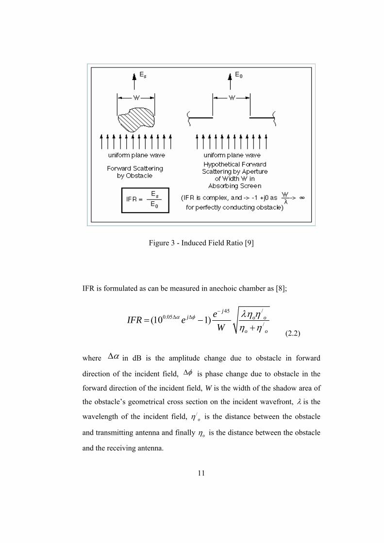
11
Figure 3 - Induced Field Ratio [9]
IFR is formulated as can be measured in anechoic chamber as [8];
/450.05
/(10 1)j
j o o
o o
eIFR eW
α φ λη ηη η
−Δ Δ= −
+ (2.2)
where αΔ in dB is the amplitude change due to obstacle in forward
direction of the incident field, φΔ is phase change due to obstacle in the
forward direction of the incident field, W is the width of the shadow area of
the obstacle’s geometrical cross section on the incident wavefront, λ is the
wavelength of the incident field, /oη is the distance between the obstacle
and transmitting antenna and finally oη is the distance between the obstacle
and the receiving antenna.
12
In typical radome applications insertion loss is around 0.1 dB. This loss can
be adoptable. However scattering loss is much more important than the
insertion loss factor. Because in antenna systems while typical radome
insertion loss is around 0.1 dB, radome scattering loss may be around 10 dB
for high frequency applications. Low IFR value is an indication of low
scattering effect in forward direction.
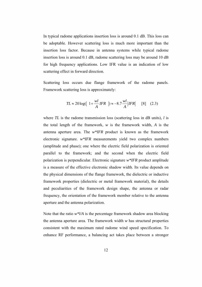
Scattering loss occurs due flange framework of the radome panels.
Framework scattering loss is approximately:
20 log( 1 ) 8.7wl wlTL IFR IFRA A
≈ + ≈ − [8] (2.3)
where TL is the radome transmission loss (scattering loss in dB units), l is
the total length of the framework, w is the framework width, A is the
antenna aperture area. The w*IFR product is known as the framework
electronic signature. w*IFR measurements yield two complex numbers
(amplitude and phase); one where the electric field polarization is oriented
parallel to the framework; and the second when the electric field
polarization is perpendicular. Electronic signature w*IFR product amplitude
is a measure of the effective electronic shadow width. Its value depends on
the physical dimensions of the flange framework, the dielectric or inductive
framework properties (dielectric or metal framework material), the details
and peculiarities of the framework design shape, the antenna or radar
frequency, the orientation of the framework member relative to the antenna
aperture and the antenna polarization.
Note that the ratio w*l/A is the percentage framework shadow area blocking
the antenna aperture area. The framework width w has structural properties
consistent with the maximum rated radome wind speed specification. To
enhance RF performance, a balancing act takes place between a stronger

13
structure with heavy-duty sized members (making w larger) and RF
performance. This RF optimization process often determines that radomes
are designed with minimal structural safety factors. In other words larger w
values increase structural strength but decrease RF performance due to the
blockage.
2.3.2.3 Importance of Frequency of Operation of the Antenna
System
The frequency band of the antenna system is also an important factor to be
considered in a high performance radome design. The material selection for
the radome is done by considering this frequency band. For example, a core
material in the radome panel may have a fine insertion loss in L-Band while
having inappropriate insertion loss factor at S or C Band etc. This is
similarly the same case for scattering loss. For example, Metal Space Frame
Radomes which have aluminum framework structure are not as impacted as
the Dielectric Space Frame Radomes from the high frequency applications.
Therefore, the material for radome panels and radome panel framework has
to be chosen by considering the frequency band of the antenna for a high
performance antenna radome design.
2.3.2.4 Importance of Using Hydrophobic Materials
There is another important issue while choosing the right material for
radome panels and panel flange framework. This issue is using hydrophobic
materials for reducing insertion and scattering losses.

14
Water has a high dielectric constant and a very high loss tangent for
microwave and millimeter wave frequencies. As a result, even thin films of
water on the surface of antennas, radomes or feed waveguides can cause
large attenuation on the transmitted or received signals.
Although use of a radome eliminates losses due to water deposited on
antenna surfaces, the radome itself can allow water to collect and increase
systems losses if the radome surface itself is not hydrophobic.
Hydrophobicity is measured with contact angle specification [10]. Contact
angle is the angle between the surface and line drawn from the point of
contact (between the surface and the water droplet) that is tangent to the
water droplet as given in Figure 4. The bigger the contact angle, the more of
a sphere the droplet is and the better the hydrophobic properties of the
material. For example a droplet of water on a non hydrophobic surface may
have a contact angle of 15° or even less. In general, materials which have
contact angles larger than 90 degrees are expressed as hydrophobic.
Figure 4- Evaluating Hydrophobicity by Measuring the Contact Angle of the Water Droplet on the Surface [10]

15
Water on the hydrophobic radome surface is in beads rather than in sheets.
If the water is in beads, the energy will be slightly diffracted because the
water droplets have dimensions much less than a wavelength at microwave
frequencies. The responses of two different materials to the water expressed
as in Figure 5. As can be seen from the figure on the hydrophobic material
water is in bead form. However, on the non-hydrophobic material water is
in sheet form which is typical feature of non-hydrophobicity.
Figure 5- Hydrophobic and Non-Hydrophobic Material Responses to Water
Typical hydrophobic materials are silicon dioxides, teflon based kevlars,
silicon oils and fluoropolymers. Usually silicon dioxides are used in
microwave antenna radome panels and flange framework to enhance
hydrophobicity.

16
As the frequency of operation increases, impact of the water on the
transmission loss (scattering loss in dB units) increases. The following
figure (Figure 6) shows the importance of hydrophobic coating on the
transmission losses.
Figure 6- Effect of Hydrophobic Coating on Transmission Loss [10]
As presented in Figure 6, when the operational frequency increases up to 30
GHz frequency the transmission loss due to the 10mm/hour rain increases to
7dB for an non-hydrophobic material, however a hydrophobic material let
only 2dB transmission loss due to the same rain impact. This figure clearly
shows the importance of hydrophobic materials for radome applications.

17
2.4 Radome Types
There are different types of radome structures for antenna systems. Each has
specific purposes, advantages considering costs, frequency of operation and
dimensions of the antenna system etc.
2.4.1 Solid Laminate Radomes
Solid laminate radomes are used in meteorological radars, commercial
satellite communications, EMI applications and fire control systems. Solid
laminate radomes are suitable for applications below 3 GHz frequencies.
Figure 7 - Solid Laminate Radome for Shipboard Data Communications [3]

18
They are composed of doubly curved fiberglass panels, sizes of which
depend on antenna size and weather conditions to stand for. The panel
thickness can be changed for different applications. For high frequency
applications SLR should be tuned. The tuning of a radome is defined and
analyzed in Chapter 4.
Figure 8 - 3.05 m Diameter Solid Laminate Radome for MK-86 Gun Fire Control System [3]
Solid laminate radomes are usually used for smaller antenna systems when
compared with DSF and MSF radomes. Usual size of SLR is between 1 and
19
5 meters in diameter [3]. Advantage of SLR is its cost effectiveness.
However, random distribution of the panels, importance of which is
presented in Chapter 4 is impossible for solid laminate radomes. This leads
to greater boresight and side lobe degradation and this is the main limit of
usage for high performance applications with solid laminate radomes [3].
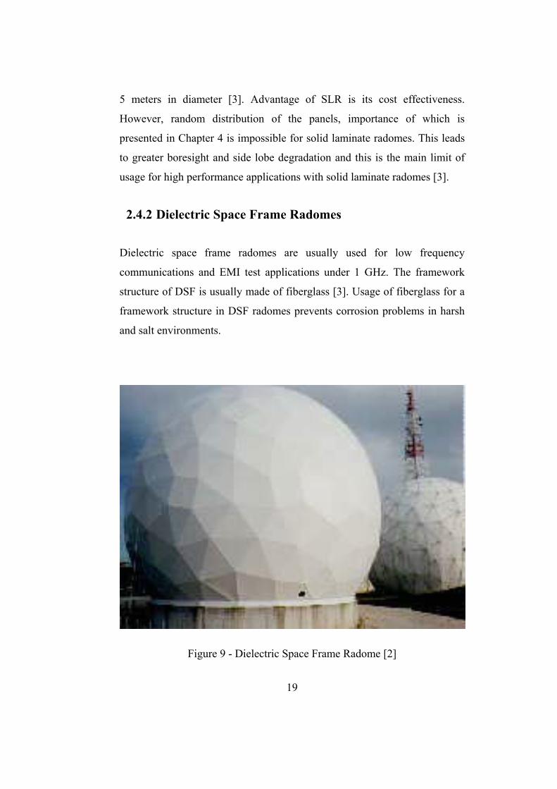
2.4.2 Dielectric Space Frame Radomes
Dielectric space frame radomes are usually used for low frequency
communications and EMI test applications under 1 GHz. The framework
structure of DSF is usually made of fiberglass [3]. Usage of fiberglass for a
framework structure in DSF radomes prevents corrosion problems in harsh
and salt environments.
Figure 9 - Dielectric Space Frame Radome [2]

20
The panels are composed of membranes which are pre-stressed to form a
rigid panel. The pre-stress process eliminates wavy, flapping panel
membranes and eliminates the need for pressurization to reduce oil-canning,
sound/vibration noise, microphonics and fatigue failure characteristics etc.
[2]. The panels can be in regular geometries or randomized geometries. Size
of DSF radomes depends between 1.8 meters and 20 meters in diameter [3].
For large antenna systems to cover the antenna larger beams of fiberglass
framework is required for structural reasons and this leads performance
degradation. Therefore for high frequency applications in general DSF is a
not logical choice. However, the electromagnetic performance of DSF can
be enhanced by tuning the dielectric framework structure as defined and
analyzed in Chapter 4. This technique broadens the frequency band of
operation of the DSF radomes.
2.4.3 Metal Space Frame Radomes
Metal space frame radomes are usually used in military and commercial
satellite communications, intelligence gathering, radio astronomy, weather
radars and 2-D surveillance radars [3]. Usual panel shapes are triangular in
MSF radomes as presented in Figure 10. These panels are bolted together to
form a geodesic dome. The framework structure of MSF is made of
aluminum. Aluminum has more powerful mechanical properties than
fiberglass used in DSF structures. This property lets using thin beams of
aluminum for framework of the panels which minimizes scattering loss of
the radome.

21
Figure 10- 14.1 m Diameter Metal Space Frame Radome [3]
It is one of most common radomes in antenna engineering. Because MSF
radomes are used between 0.5 GHz and 100 GHz with high performances
and this feature makes them unique. Even there are examples of usage up to
1000 GHz with high performance panels [3]. This is an important advantage
when compared with Dielectric Space Frame radomes. Another advantage
of Metal Space Frame radome is the size of the radome structure. Since the
elastic modulus of the framework material is quite high, it is possible to
design MSF radomes up to 60 meters in diameter using thin beams of
Aluminum for the framework structure. Moreover thickness of triangular
panels can be varied by considering the structural performance and the

22
operating frequency of the antenna system to have optimum characteristics
by minimizing insertion loss of the radome structure.
2.4.3.1 Structural Comparison of Dielectric Space Frame
Radomes and Metal Space Frame Radomes
Both Dielectric Space Frame (DSF) and Metal Space Frame (MSF) radomes
are assembled from many panels, which are composed of a structural
framework with attached thin membrane walls. For the Dielectric Space
Frame (DSF) radome, the radome panel framework and rigid membrane
walls are laminated one piece monolithic units manufactured form
Fiberglass Reinforced Plastic (FRP) materials. The panel flanges form the
radome framework. In contrast for the Metal Space Frame (MSF) radome,
the thin membrane wall is attached to an Aluminum metal framework. To
accomplish the attachment process, the membrane material must be very
pliable. The usual panel material choice is Dacron in MSF radomes [2].
While dielectric space frame FRP radomes have a rigid membrane wall, a
Dacron membrane wall in metal space frame radome is easily recognizable
by flapping panel membranes. At moderate wind speed levels, Metal Space
Frame radomes have to require pressurization to reduce membrane oil-
canning, sound/vibration noise, microphonics and fatigue failure. The panel
membrane material has a significant and major role in determining the
strength of the radome structure. Although the framework material of the
Metal Space Frame radome Aluminum is much stronger than Fiberglass
Reinforced Plastic (FRP) material, which is the core material of Dielectric
Space Frame radome, MSF is weaker than DSF. This is the reason of
structural degradation effect of panel membranes of MSF. Dielectric Space
Frame radomes are stronger than the Metal Space Frame radomes to the
23
harsh weather conditions such as wind and corrosion with the well-built
panel membranes.
Considering structural strength of the radome types usually there are two
parameters in the literature. They are critical buckling wind speed and safety
factor. Critical buckling wind speed shows the maximum wind speed that
the radome can be sustained safely. Safety factor shows the radome
structural performance in a fixed wind speed. For a structural point of view,
high values for critical buckling wind speed and safety factor shows the
strength of the radome structure. It is a figure of merit for considering
structural performances of radomes.
Table 1 demonstrates the critical buckling speed and safety factor for
identical 41ft (12.6m) space frame radomes. In each case, the framework
member size (width and depth) is the same for both radome types. Only
Aluminum material properties are substituted for the FRP material in DSF
and Dacron thin membrane wall material properties are substituted for FRP
in DSF. As presented at the table the dielectric space frame radome is 150
percent stronger than the metal space frame unit. While the dielectric space
frame radome 2.5 safety factor is adequate for a 323 km/hr wind speed
requirement, the equivalent metal space frame radome has only a 1.0 safety
factor. The only way for the metal space frame radome to safely meet a 323
km/hr specification wind speed is to increase the Aluminum framework
member size or change the membrane to a stronger material. Since a flexible
membrane material is necessary for the fabrication of the metal space frame
panel, there is little choice but to stay with Dacron. Therefore, only decision
available for the metal space frame radome is increasing the Aluminum
framework member size. There is, however, a penalty to pay for increasing
the Aluminum framework size. This penalty comes in the form of a

24
simultaneous increase in transmission loss and deterioration of RF
performance.
Table 1- Structural Comparison of Metal Space Frame Radomes and Dielectric Space Frame Radomes [2]
Radome Design
Parameter
Dielectric Space Frame
Radome (DSF)
Metal SpaceFrame
Radome (MSF)
Typical Space Frame Radome Picture
Flange Framework
Material
FRP Aluminum
Panel Membrain Material
FRP Dacron
Critical Buckling
Wind Speed
509 km/h 323 km/h
Safety Factor at 320 km/h
Wind Speed
2.50 1.01

25
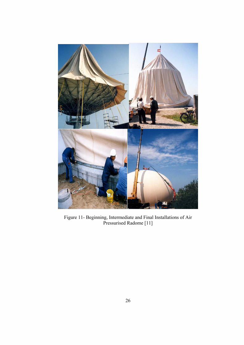
2.4.4 Air Pressurised Radomes
Air pressurised radomes are the easiest type of radomes considering
implantation of a radome structure. They resemble like pressurised baloons.
Figure 11 represents a typical installation of an air pressurized radome
structure. Inside air pressurised radomes there are inflation blowers for
pressurising operation. The mechanical protection of the antenna system is
gathered by pressurising the cover coating at a variant pressure optimized
for outside wind speed. There is no flange framework for this radome as
presented in figure 11. Outermost radome structure is composed of just the
teflon based cover protecting the antenna system inside.
The frequency performance of operation totally depends on the
electromagnetic characteristics of the material used in radome cover. Usual
applications of these type radomes are below 20 GHz. They are easily
implantable and transportable. However, the mechanical properties are less
powerful than other type of radome structures. They are suitable for low
cost and low period usage system designs.
26
Figure 11- Beginning, Intermediate and Final Installations of Air Pressurised Radome [11]

27
2.5 Sandwich Type Radomes
Sandwich type radomes are used for high performance, discrete narrow
bandwidth large antenna system applications as seen in Figure 12. Typical
applications where the sandwich type radomes have been used are 3-D
military and commercial radar applications, air traffic controlling and other
radar systems such as weather radar, phased array radar, secondary
surveillance radar etc [3]. Sandwich type radomes are very important
especially for discrete narrow band applications.
Figure 12 -Sandwich Type Radome with Large Access Doors [3]

28
2.5.1 Features of Sandwich Type Radomes
Sandwich type radomes have multi layered geometrical construction. This
property totally differs them from other types of radomes. Three layer
sandwich radomes are named as Type-A Sandwich Radomes and they are
the most common sandwich type. There are also three layered sandwich
radomes which have core materials at inner and outermost part of the
radome named as Type-B and there are five layered sandwich radomes
which are named as Type-C Sandwich Radomes as seen in Figure 13.
Figure 13- Sandwich Radome Types [13]

29
The name “sandwich” comes from the multi-layered structure of the
radome. Sizes of sandwich radomes may change between 3 and 24 meters in
diameter [3]. Multi-layered polygonal panels on sandwich radomes are
bolted together to form truncated sphere radome geometry. Panels have
highly composite materials which increase consistency and mechanical
strength of the radome structure. Outermost and inner most surfaces of the
panels are made of fiberglass. Main core of the panel structure include
composite honeycomb materials such as Kevlar, Polyurethane, Resin filled
3D-glass, etc. Some examples of the materials are given in Figure 14 and
Figure 15. Main core is the main part of creation of temperature difference
between inside an outside. Thickness of the main core depends on the
requirement level of the protection of antenna system and antenna personnel
inside for harsh weather conditions.
Figure 14- 3D Glass Material Used in Core Part of Type-A Sandwich Radomes [19]

30
Figure 15- Honeycomb Core Materials Used in Type-A Sandwich Radomes [19]
Smith chart is also useful when determining optimum thickness of sandwich
radomes. Besides thermal insulation property, foam core increases water
rejection properties and also provides greater impact strength and consistent,
high radar transparency without sacrificing weight and structural stability,
thereby providing a much longer service life in moisture/impact critical
environments. Also, thickness of the foam core can be arranged to have
optimum insertion loss characteristics considering the specific frequency
band of operation of the antenna system inside which increases radar
transparency of sandwich type radomes.
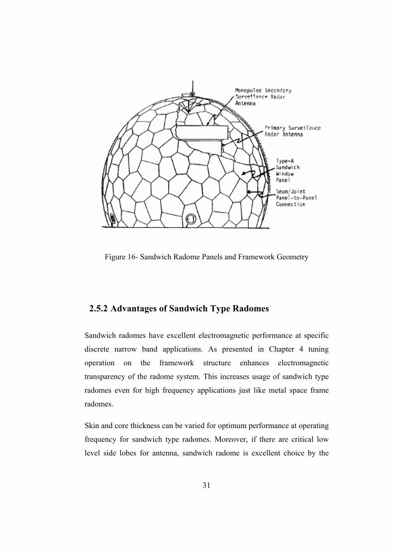
Multi layered panels on the sandwich radomes are attached each other by
seams as in figure 16. As expressed before because of shipping and
transportation issues large antenna radomes have to be composed of
different panels. The framework is composed of the seams which are the
structures which put these highly composite multi layered panels together in
sandwich type radomes. Electromagnetic importance of seams in sandwich
type radomes are investigated in section 2.5.4.
31
Figure 16- Sandwich Radome Panels and Framework Geometry
2.5.2 Advantages of Sandwich Type Radomes
Sandwich radomes have excellent electromagnetic performance at specific
discrete narrow band applications. As presented in Chapter 4 tuning
operation on the framework structure enhances electromagnetic
transparency of the radome system. This increases usage of sandwich type
radomes even for high frequency applications just like metal space frame
radomes.
Skin and core thickness can be varied for optimum performance at operating
frequency for sandwich type radomes. Moreover, if there are critical low
level side lobes for antenna, sandwich radome is excellent choice by the

32
arrangement property of panel thickness and seam geometry. Also, panel
removal and repair is much easier than other radome types.
2.5.3 Disadvantages of Sandwich Type Radomes
There are some drawbacks of sandwich type radomes. Geometric design
before implantation is very critical for sandwich radomes because tooling is
required for each changing size. Moreover, electromagnetic performance is
frequency discrete [3]; in other words they don’t give high performance for
large frequency bands of operation. For example, a sandwich radome design
for an antenna operating at 5 GHz may not be used as the same performance
with the same antenna dimensions for 20 GHz. Furthermore, manufacturing
tolerance of panels and joint design of the panels by the seams is very
critical to have high performance designs. These features make sandwich
type radomes the most expensive solution among other type of radome
types.
2.5.4 Importance of Framework Structures in Sandwich
Type Radomes
Sandwich radome multi layered panels are attached each other by the seams.
These seams constitute the framework structure of the sandwich type
radomes. The physical dimensions of the seams are usually determined by
structural considerations, such as maximum wind speed and the resultant
stress that the seams have to sustain. However, without electromagnetic

33
consideration the seams may degrade total system performance by
introducing high scattering values [12].
Panels of sandwich radomes are specially manufactured to have minimum
insertion loss at required insulation values. Typical transmission loss of the
panels is around 0.1 dB depending on the discrete frequency of operation.
However, the scattering loss of the framework of the panels (seams) maybe
4 to 100 times greater without electromagnetic consideration. To have high
performance sandwich radome design, electromagnetic analysis of the seam
structure has to be done at first. Then to minimize the scattering effect of
seam structure, solutions have to be found. The following chapter (chapter
3) is devoted to the electromagnetic analysis of the framework of the
sandwich type radomes. In chapter 4, to enhance electromagnetic
transparency of sandwich type radomes different design methods are
presented and investigated.
2.5.5 Structural and Electromagnetic Comparison of
Different Sandwich Radome Framework Geometries
As expressed in this chapter the radome must be packaged for shipment for
worldwide transportation. What this means is that the maximum panel size
must conform to standard shipping sizes. Therefore it should be designed
such that the whole radome has to be composed of panels which are
transported to the place of the antenna system and installed there. Taking
into account shipping size constraints, two common sandwich radome
framework geometry types can be found in the market, which are the
symmetric orange peel and quasi-random geometries shown in Figures 17
and Figure 18, respectively.

34
Figure 17- Typical Quasi Random Sandwich Radome Geometry
Figure 18 – Typical Orange Peel Sandwich Radome Geometry

35
Quasi-random geometrical sandwich radomes may have triangular,
hexagonal or pentagonal panel shapes. A geodesic radome using triangular
panels is an alternate implementation of the quasi-random radome geometry.
Orange peel radome panels have usually flat planes for production and
installation easiness. Usually they have lower cost and they are used for low
budget antenna systems.
Quasi-random geometrical sandwich radome structures have important
electromagnetic transparency properties while compared with orange-peel
type sandwich radomes. As discussed in Chapter 4 the scattering
electromagnetic field components of each sandwich radome seam should
not be added directly to have high total scattered field components which
have important effects especially on low side lobe levels of the original
antenna electromagnetic field. In quasi-random type sandwich radome
structures, since the seam geometries are distributed in arbitrary direction
the cumulative effect is very low while compared with the orange-peel type
geometries.
There are also structural issues for design considerations between two
different sandwich radome types, because the main aim of the radome is to
protect the antenna from harsh weather conditions. Table 2 is a structural
comparison between Quasi-Random geometrical sandwich radome and
Orange-Peel geometrical sandwich radome type for 10.7m diameter length.
This table shows that quasi-random radome geometry is significantly
stronger than the symmetric orange peel geometry. The quasi-random
radome is 119 percent stronger than the symmetric orange peel unit and has
an appropriate safety factor of 2.19 for a 240km/hr specification wind speed.
In contrast, the symmetric orange peel radome only has 240km/h critical
buckling speed and a safety factor of 1.0. Therefore using Quasi-Random

36
geometric structures in sandwich radomes enhances both electromagnetic
and structural performances of the system.
Table 2- Structural Comparison of Quasi Random Sandwich Radome Geometry and Orange-Peel Sandwich Radome Geometry
Radome Geometry
Critical Buckling
Wind Speed
Safety FactorAt 240 km/h Wind Speed
Typical Radome Geometry Scheme
Quasi-Random
357 km/hr
2.19
Orange Peel
241km/h
1.00
37
CHAPTER 3
ELECTROMAGNETIC SCATTERING ANALYSIS
OF SEAMS IN SANDWICH TYPE RADOMES
3.1 General Information
In this chapter electromagnetic scattering analysis of sandwich radome is
presented. In the analysis, electromagnetic scattering from the arbitrary
distributed radome seams are analyzed. For the purpose of computing the
scattering electromagnetic field from the seams of sandwich radomes, it is
required to imitate the seams to a known geometrical object with certain
properties. For example in [12] scattered electromagnetic field is obtained
by assuming the sandwich radome seams as perfectly conducting strips that
radiate with the given incident field of the antenna. In this thesis work,
sandwich radome seams are assumed to be circular cylinders which are
composed of conducting cylinders coated with dielectrics to have close
assumption for the real case of tuned sandwich radome seam structure
which is presented in Chapter 4. In the analysis, lengths of the cylinders are
assumed as infinite, since they are placed in the near zone and block the
aperture of the antenna. To formulate the scattering field from the seams,
there is also need to know the near field of the antenna covered by the
38
sandwich radome [12]. Analysis technique in this thesis work is applicable
for all types of antenna systems with the condition of knowledge of near and
far electromagnetic field formulations of the systems. Analysis in this thesis
work is done for a transmitting antenna covered by the sandwich radome
such that near incident field of the antenna is scattered from the framework
structure and constitute total far electromagnetic fields with antenna original
far field together. For the reciprocal case of a receiving antenna, this
analysis is valid with the condition of knowledge of incident fields on the
framework structure of the sandwich radome.
In the analysis, pyramidal horn type antenna is used as a transmitting
antenna as a case study. The effect of scattering is emphasized by
comparing total far electromagnetic field of the antenna and radome
structure together with far electromagnetic field of the antenna without
radome structure. Finally, total far electromagnetic field is expressed as the
summation of antenna far electromagnetic field and the scattered field due
to radome structure for both transverse electric and transverse magnetic
incident field radiation by the antenna inside the sandwich radome.
3.2 Scattering Analysis of Radome Seams
In the scattering analysis, after having the assumptions for the physical and
geometrical assumptions of the seam structure, there exists another
requirement which is information on near electromagnetic field of the
antenna system inside the radome. Near electromagnetic field of the antenna
system is required to define the incident field to obtain the scattered
electromagnetic field from the seam structure. This combination gives the
enough information to define the scattered field from the seam structure of a
sandwich radome [12],[17]. In this section the analysis is done considering

39
single seam, in the next section, this analysis is generalized for arbitrary
distributed M number of sandwich radome seams.
The scattered E-Field from the sandwich radome seam [18] can be
explained as:
'( , , )s incidentE E f r φ ψ= (3.1)
where sE represents electric field scattered by the seam in the far
zone, incidentE represents the incident field generated by the antenna.
'( , , )f r φ ψ is the function that relates the incident electric field to the
scattered electric field by the seam structure. In this function r represents
the distance from the point P, where the far-electromagnetic field is
gathered to the axis of sandwich radome seam which is considered in
cylindrical geometry as presented in Figure 19. 'φ represents the angle of
this far field point with the x-axis. ψ represents the angle between incident
propagating electromagnetic field generated by the antenna and cylinder
axis normal. For example, if 0ψ = , this shows a normal incidence of
electromagnetic field to the sandwich radome seam, if 0ψ ≠ , this shows an
oblique incidence to the sandwich radome seam as presented in Figure 19.

40
Figure 19 - Scattering Geometry of the Analysis
It is assumed that dielectric coated perfectly conducting cylinder with a total
radius of 0a is positioned along z-axis. Considering the same geometry
transverse electric (TE) and transverse magnetic (TM) analysis is done
separately.
In the TE analysis, it is assumed that TE incident field of radiation is
generated by the antenna. Scattered electromagnetic field by the coated
cylinder sTEE is expressed as [18] :
'( , , )sTE TEincE E f r φ ψ= (3.2)
'φ
r
incE
ψ
P
u

41
Scattered electric field from the seam structure can be decomposed into the
vector coefficients such as sTEzE and sTEEφ as [18] :
0 sin (1) '0(cos )( ) ( ) ( cos )
njk zsTE TE n jn
z inc n nn
E E e j C H k r eψ φψ ψ=∞
=−∞
= −∑ (3.3)
0 sin
(1)0 2
0
(1)' '0
(cos )( )
( sin )( ) [ ( cos )cos
( cos )]cos
jk zsTE TEinc
nn
n nn
TE jnn n
E E e
nj C H k rk r
j C H k r e
ψφ
φ
ψ
ψψψ
ψψ
=∞
=−∞
=
−−
+
∑ (3.4)
where (1)H is the Hankel function of the first kind, and 0k is the wave
number such as 0 0 0k w μ ε= . Primes in Hankel functions represent the
derivation of the function. nC and TEnC are the series coefficients given
below:
2 (1)0 0(1) 2
0
( ) ( )[ ( )]
TE n n n n nn
n n n n
M N q J x H xCP N q H x
−= −
− (3.5)
0(1) 2
0 0
2 [ ][ ( )]
nn
n n n n
s qC jx P N q H xπ
=− (3.6)
where 0x , nq and 0s are expressed as:
(3.7)
0 0 0 cosx k a ψ=

42
(3.8)
(3.9)
and ,r rε μ are the relative permittivity and permeability coefficients of the
coated cylinder, respectively.
where , ,n n nP M N appearing in above equations are defined as:
(1) (1) '0 0( ) ( )n n n nP H x Y H x= − (3.10)
0 0( ) '( )n n n nM J x Y J x= − (3.11)
(1) (1) '0 0( ) ( )n n n nN H x Z H x= − (3.12)
where nY and nZ are expressed as:
(1) ' (1) '0 1 2 1 2
' (1) ' (1) ' '1 1 2 1 2
( ) ( ) ( ) ( )( ) ( ) ( ) ( )
n n n nn
n n n n
s J x H x H x J xYr J x H x H x J x
−=
− (3.13)
(1) (1)0 1 2 1 2
' (1) (1) '1 1 2 1 2
( ) ( ) ( ) ( )( ) ( ) ( ) ( )
n n n nn
n n n n
s J x H x H x J xZs J x H x H x J x
−=
− (3.14)
01
coss
ψ=
2 20 0
sin 1 1( )sin cosn
r r
nqk a
ψε μ ψ ψ
= −−

43
where 1a represents radius of the perfectly conducting part and 0a is the
total radius of the coated cylinder with,
21 0 0 sinr rx k a μ ε ψ= − (3.15)
22 0 1 sinr rx k a μ ε ψ= − (3.16)
1 2sinr
r r
r μ
μ ε ψ=
− (3.17)
1 2sinr
r r
s εε μ ψ
=−
(3.18)
Near incident field of the antenna is taken from a pyramidal horn type
antenna as a case study. Horn antenna is assumed to have small flare angle
such that uniform phase distribution on the aperture is obtained. Moreover,
it is assumed that antenna aperture field distributions are not affected with
sandwich radome seams placed in the near field of the antenna.
There are different ways for calculating near field of horn type antennas. For
example, aperture of the antenna can be divided into minimized sub-
apertures. Summation of the far field distributions of these sub-apertures
constitutes the near field of the horn antenna. Also, near field of the horn
antenna can be related with the input power, gain of the antenna and the
distance where the near field is obtained such that near field of the horn
antenna can be taken as [16] :

44
0 14incidentPGE
uη
π= (3.19)
where incidentE represents near field of the antenna, 0η is the free space wave
impedance, P is the input power of the antenna, G is the power gain of the
antenna and u is the distance of the seam from the aperture as presented in
figure 19.
G can be taken as [16] :
G 21,6 f a= (3.20)
where f is the operating frequency of the antenna in Gigahertz and a is the
larger of the two cross-sectional dimensions of the aperture in meters.
Finally scattered transverse electric far electromagnetic field of the antenna
and sandwich radome seam is found as follows:
0 sin0
(1)0 2
0
(1) ' '0
(1) '0
1[ cos ]
( sin )[ ( ) ( cos )cos
( cos )]cos
( ) ( cos ) ]
sTE jk z
nn
n nn
TE jnn n
nn jn
n n zn
P 21,6 f aE e4 u
nj C H k rk r
j C H k r e a
j C H k r e a
ψ
φφ
φ
η ψπ
ψψψ
ψψ
ψ
=∞
=−∞
=∞
=−∞
=
−− +
+ −
∑
∑
(3.21)

45
Transverse magnetic (TM) wave scattered from the sandwich radome seam
is analyzed similarly assuming incident radiation from the inside antenna as
the following [18]:
0 sin (1) '0(cos )( ) ( ) ( cos )
njk zsTM TM n TM jn
z inc n nn
E E e j C H k r eψ φψ ψ=∞
=−∞
= −∑ (3.22)
0 sin
(1)0 2
0
(1)' '00
0
cos
( sin )( ) [ ( cos )cos
( cos )]cos
jk zsTM TMinc
nn TM
n nn
jnn n
E E e
nj C H k rk r
j C H k r e
ψφ
φ
ψ
ψψψ
μ ψψ ε
=∞
=−∞
=
−−
−
∑ (3.23)
where TMnC is expressed as the following:
2 (1)0 0(1) 2
0
( ) ( )[ ( )]
TM n n n n nn
n n n n
V P q J x H xCP N q H x
−= −
− (3.24)
with,
'0 0( ) ( )n n n nV J x Z J x= − (3.25)
Finally, scattered transverse magnetic field of the antenna and sandwich
radome structure is found to be:
46
'
sin (1) '0
sin (1)0 2
0
(1) '00
0
cos ( ) ( cos )
sincos ( ) [ ( cos )( )cos
( ) ( cos )]cos
o
o
nsTM jk zTM n TM jninc n n z
nn
jk zTM n TMinc n n
n
jnn n
E E e j C H k r e a
nE e j C H k rk r
j C H k r e a
ψ φ
ψ
φφ
ψ ψ
ψψ ψψ
μ ψψ ε
=∞
=−∞
=∞
=−∞
= − +
−−
−
∑
∑
(3.26)
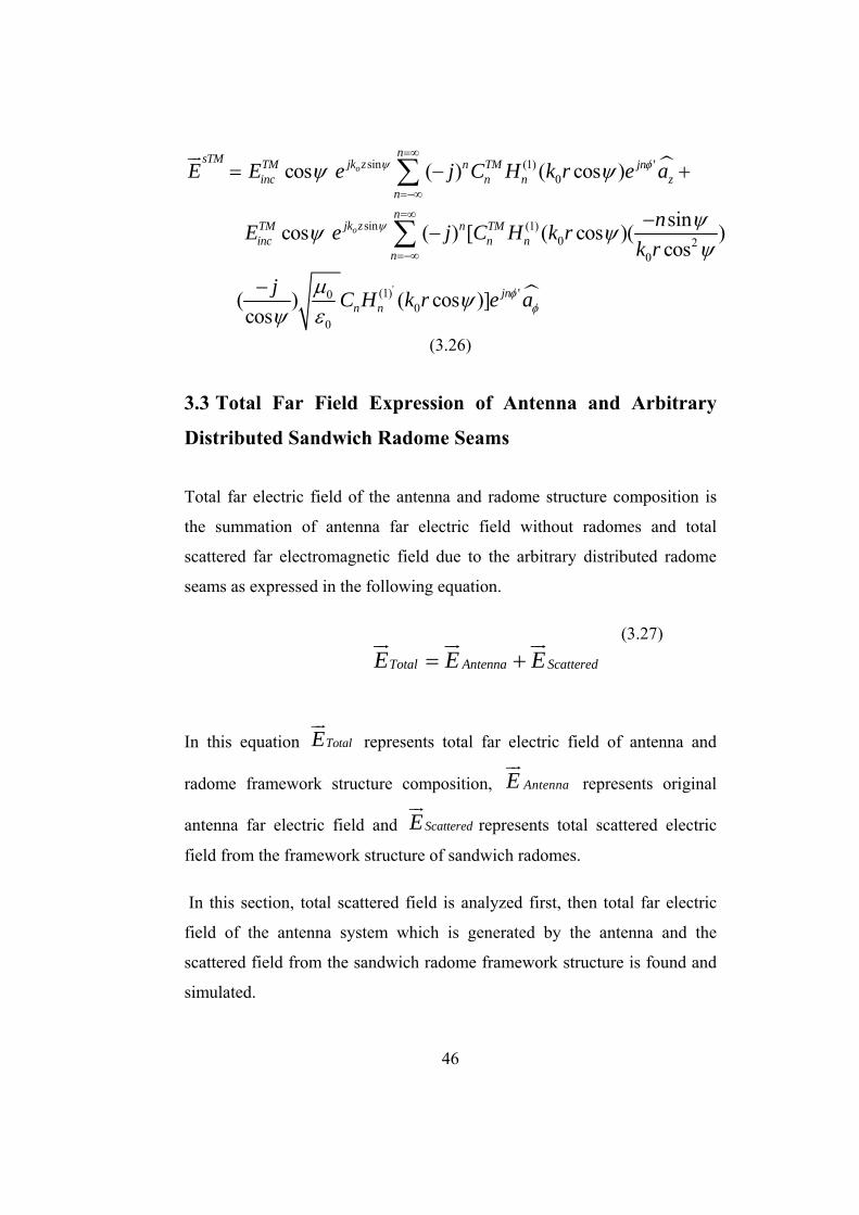
3.3 Total Far Field Expression of Antenna and Arbitrary
Distributed Sandwich Radome Seams
Total far electric field of the antenna and radome structure composition is
the summation of antenna far electric field without radomes and total
scattered far electromagnetic field due to the arbitrary distributed radome
seams as expressed in the following equation.
(3.27)
In this equation TotalE represents total far electric field of antenna and
radome framework structure composition, AntennaE represents original
antenna far electric field and ScatteredE represents total scattered electric
field from the framework structure of sandwich radomes.
In this section, total scattered field is analyzed first, then total far electric
field of the antenna system which is generated by the antenna and the
scattered field from the sandwich radome framework structure is found and
simulated.
Total Antenna ScatteredE E E= +

47
To obtain a general solution for seam scattering, the analysis done in
previous section is generalized including the arbitrary distributed seams in
front of the antenna system. Assume the angle between incident propagating
electromagnetic field and the thm sandwich radome seam is given as mψ .
Assuming there are M radome seams, far electromagnetic scattered field by
the arbitrary distributed sandwich radome seams is expressed as:
0 sin
1
(1)0 2
0
(1) ' '0
(cos )( )
( sin )( ) [ ( cos )cos
( cos )]cos
m
Mjk zsTE TE
inc mm
nn m
n n mn m
TE jnn n m
m
E E e
nj C H k rk r
j C H k r e
ψφ
φ
ψ
ψψψ
ψψ
=
=∞
=−∞
=
−−
+
∑
∑ (3.28)
0 sin
1
(1) '0
cos
( ) ( cos )
m
Mjk zsTE TE
z inc mm
nn jn
n n mn
E E e
j C H k r e
ψ
φ
ψ
ψ
=
=∞
=−∞
=
−
∑
∑ (3.29)
2 (1)0 0(1) 2
0
( ) ( )[ ( )]
TE n n n n nn
n n n n
M N q J x H xCP N q H x
−= −
− (3.30)

48
0(1) 2
0 0
[ ][ ( )]
nn
n n n n
s q2C jx P N q H xπ
=− (3.31)
where 0x , nq and 0s are expressed as:
(3.32)
(3.33)
(3.34)
Also note that since far electromagnetic field scattering is analyzed here, the
distance r between the seams and far electromagnetic field measurement
point is taken the same with the assumption of all the seams in the near field
are close each other compared with the far field distances. Same claim is
valid for the angle 'φ .Since the scattered field is gathered far away from the
seam structures, the angle 'φ is kept as same for distributed sandwich
radome seams which are close each other when compared with the far field
distances.
,r rε μ are the relative permittivity and permeability of the coated cylinder
shown in Figure 19.
where , ,n n nP M N is defined as:
0 0 0 cos mx k a ψ=
01
cos m
sψ
=
2 20 0
sin 1 1( )sin cos
mn
r r m m
nqk aψ
ε μ ψ ψ= −
−

49
(1) (1) '0 0( ) ( )n n n nP H x Y H x= − (3.35)
0 0( ) '( )n n n nM J x Y J x= − (3.36)
(1) (1) '0 0( ) ( )n n n nN H x Z H x= − (3.37)
where nY and nZ are expressed as:
(1) ' (1) '0 1 2 1 2
' (1) ' (1) ' '1 1 2 1 2
( ) ( ) ( ) ( )( ) ( ) ( ) ( )
n n n nn
n n n n
s J x H x H x J xYr J x H x H x J x
−=
− (3.38)
(1) (1)0 1 2 1 2
' (1) (1) '1 1 2 1 2
( ) ( ) ( ) ( )( ) ( ) ( ) ( )
n n n nn
n n n n
s J x H x H x J xZs J x H x H x J x
−=
− (3.39)
where 1a represents radius of the perfectly conducting part and 0a is the
total radius of the thm coated cylinder with,
21 0 0 sinr r mx k a μ ε ψ= − (3.40)
22 0 1 sinr r mx k a μ ε ψ= − (3.41)

50
1 2sinr
r r m
r μμ ε ψ
=−
(3.42)
1 2sinr
r r m
s εε μ ψ
=−
(3.43)
Then, total transverse electric scattered field is found as:
0 sin
1
(1)0 2
0
'(1) '0
'(1)0
cos
( sin )[ ( ) [ ( cos )cos
( cos )]cos
( ) ( cos ) ]
m
MTE jk zTEScattered inc m
m
nn m
n n mn m
jnTEn n m
m
njnn
n n m zn
E E e
nj C H k rk r
j C H k r e a
j C H k r e a
ψ
φφ
φ
ψ
ψψψ
ψψ
ψ
=
=∞
=−∞
=∞
=−∞
=
−− +
+ −
∑
∑
∑
(3.44)
Similarly, total far electromagnetic scattered field by the sandwich radome
seam with incident radiation for the transverse magnetic case is found as:
0 sin (1) '0
1cos ( ) ( cos )m
M njk zsTM TM n TM jn
z inc m n n mm n
E E e j C H k r eψ φψ ψ=∞
= =−∞
= −∑ ∑
(3.45)
51
0 sin
1
(1)0 2
0
(1) ' '00
0
cos
( sin )( ) [ ( cos )cos
( cos ]cos
m
Mjk zsTM TM
inc mm
nn TM m
n n mn m
jnn n m
m
E E e
nj C H k rk r
j C H k r e
ψφ
φ
ψ
ψψψ
μ ψψ ε
=
=∞
=−∞
=
−−
−
∑
∑ (3.46)
where TMnC is expressed as the following:
2 (1)0 0
(1) 20
( ) ( )[ ( )]
TM n n n n nn
n n n n
V P q J x H xCP N q H x
−= −
− (3.47) with,
'0 0( ) ( )n n n nV J x Z J x= − (3.48)
Finally, scattered transverse magnetic field of the antenna and M arbitrary
distributed sandwich radome structure is found to be:

52
0
0
sin
1
(1) '0
sin
1
(1)0 2
0
(1) ' '00
0
cos
( ) ( cos )
cos
sin( ) [ ( cos )cos
( cos )]cos
m
m
MsTM jk zTMinc m
mn
n TM jnn n m z
nM
jk zTMinc m
mn
n TM mn n m
n m
jnn n m
m
E E e
j C H k r e a
E e
nj C H k rk r
j C H k r e a
ψ
φ
ψ
φφ
ψ
ψ
ψ
ψψψ
μ ψψ ε
=
=∞
=−∞
=
=∞
=−∞
=
−
+
−−
−
∑
∑
∑
∑
(3.49)
Pyramidal horn type antenna which has aperture on the x-y plane with the
aperture dimensions a and b has far electromagnetic field for 10TE (the
dominant field) is expressed [17] as given in Appendix:
{ }00
00
0
0
2 20
0 0
2 20 0
sin( sin sin )2[ sin
sin sin2
cos( sin cos )2[ ]
4( sin cos )2
sin( sin sin ) cos( sin cos )2 2(cos )[ ] ]
sin sin 4( sin cos )2 2
jk RANTENNA
bkjkE E abe bR k
akaak
b ak kab ak k
θ
φ
θ φφ
θ φ
θ φ
π θ φ
θ φ θ φφ
θ φ π θ φ
−=
+−
−
(3.50)

53
where a and b is the aperture dimensions, 0k is the wave number.
Scattering from the sandwich radome structure is expressed in cylindrical
coordinates. For a final solution the far electromagnetic field of the scattered
field should be expressed in spherical coordinates to have vector summation
of the antenna original field and scattered field by the sandwich radome
seams.
To express the scattered field in spherical coordinates, defined distances and
coefficients should be transformed such as:
sinr R θ= (3.51)
φ φ= (3.52)
cosz R θ= (3.53)
sin 0 coscos 0 sin
0 1 0
R r
z
A AA AA Aθ φ
φ
θ θθ θ
⎡ ⎤ ⎡ ⎤ ⎡ ⎤⎢ ⎥ ⎢ ⎥ ⎢ ⎥= −⎢ ⎥ ⎢ ⎥ ⎢ ⎥⎢ ⎥ ⎢ ⎥ ⎢ ⎥⎣ ⎦ ⎣ ⎦⎣ ⎦
(3.54)
Then, found TEScatteredE is expressed in spherical coordinates as:

54
0 cos sin
1
'(1)0
(1)0
'(1) '02
0
cos
[[ ( ) ( sin cos ) ( sin ) ]
[ ( ) [ ( sin cos )
( sin ) ( sin cos )] ]sin cos cos
m
Mjk RTE
inc mm
njnn
n n mn
nn
n n mn
jnTEmn n m
m m
E e
j C H k R e a
j C H k R
n j C H k R e ak R
θ ψ
φθ
φφ
ψ
θ ψ θ
θ ψ
ψ θ ψθ ψ ψ
=
=∞
=−∞
=∞
=−∞
− −
+ −
−+
∑
∑
∑
(3.55)
Finally, TotalE which is the total far electromagnetic field of the antenna and
sandwich radome structure is found as given in equation (3.27). TotalE is
equal to:
55
{ }
0
0
cos sin0
1
'(1)0
00
0
0
0
2 20
(1)
1 cos
[[ ( ) ( sin cos ) ( sin )]
sin( sin sin )2[ sin
sin sin2
cos( sin cos )2[ ]
( sin cos )2
[ ( ) [
m
Mjk R
Total mm m
njnn
n n mn
jk R
nn n
P 21,6 f aE e4 u
j C H k R e
bkjk E abe bR k
akaa4 k
j C H
θ ψ
φ
θ
η ψπ
θ ψ θ
θ φφ
θ φ
θ φ
π θ φ
=
=∞
=−∞
−
=
− − +
−
+ −
∑
∑
0
0 20
'(1) '0
00
0
0
0
2 20
( sin )( sin cos )sin cos
( sin cos )] ]cos
sin( sin sin )2(cos )
sin sin2
cos( sin cos )2[ ] ]
( sin cos )2
nm
mn m
jnTEn n m
m
jk R
nk Rk R
j C H k R e
bkjk E abe bR k
akaa4 k
φ
φ
ψθ ψθ ψ
θ ψψ
θ φφ
θ φ
θ φ
π θ φ
=∞
=−∞
−
−
+
+
−
∑
(3.56)
Note that total field is expressed as the summation of the antenna far
electromagnetic field for the dominant mode ( 10TE ) and the total scattered
field with this mode accordingly. Also note that, mu in the final equation
represents the distance between the thm sandwich radome seam and the

56
aperture of the antenna. The effect of this distance on the electromagnetic
field pattern is discussed in the following section via the simulations.
3.4 Simulations Based on the Analysis
This section is devoted to the simulations based on the electromagnetic
scattering analysis of the sandwich radome seams in this chapter. Antenna
original far electromagnetic field is compared with the total far
electromagnetic field which is the combination of antenna original far
electromagnetic field and the scattered electromagnetic field of arbitrary
distributed sandwich radome seam structure.
At resonant frequency of 1 GHz with the dimensions of a= 76,2 cm ( 2,54λ )
and b= 55,9 cm(1,86λ ) with 1 kw input power, first the horn antenna far
electromagnetic field characteristics for the dominant mode( 10TE ) is
obtained. Then, the far electromagnetic field pattern characteristics of
horizontal cylinder ( 0ψ = ) with the distance from the aperture of horn
antenna as 6λ ( 6u λ= ) is obtained. As a realistic approach the coated
cylinder diameter is taken as 0 6a = cm and 1 1a = cm. Finally, far
electromagnetic field pattern characteristics for 7 seam structures (M=7)
with the angle of inclination 30mψ = for m=1,2,3,4,5,6 and 0mψ = for
m=7, assuming the same distance ( 6mu λ= ) from the aperture centre is
obtained.
The graph presented in Figure 20 contains all three E-Field pattern
characteristics expressed above. The characteristics shown in blue color is
the horn antenna original total far E-Field pattern characteristics. The

57
characteristic in green color shows the combination of scattered E-Field of
single horizontal dielectric coated cylinder which is placed at 6u λ=
distance from the aperture and the horn antenna original total far E-Field
characteristics. Finally the characteristic in red color shows the total E-Field
pattern characteristics of horn antenna and 7 seam structures with the angle
of inclination 30mψ = for m=1,2,3,4,5,6 and 0mψ = for m=7, assuming
6mu λ= distance from the aperture centre. As it can be observed from the
graphs the seam structures lead to distortions on the original antenna field
characteristics as the number of seam structures increases. New side lobes
are generated with various levels and directions. This is clearly presented
with multi numbered sandwich radome seam distribution. Typically these
are the effects of scattering electromagnetic fields of the seams in the near
field of the antenna.

58
Figure 20- Far E-Field Characteristics of Antenna and Different Sandwich Radome Seam Distributions
Horn Antenna
Horn Antenna and Single Horizontal Seam
Placed at 6λ Distance
Horn Antenna and 7 Seams Placed at
6λ Distance E-Field
[V/m]
Theta Angle Variation [deg], Phi = 90°
Total E-Field Characteristics of Horn Antenna and Sandwich Radome Seam Distributions
58
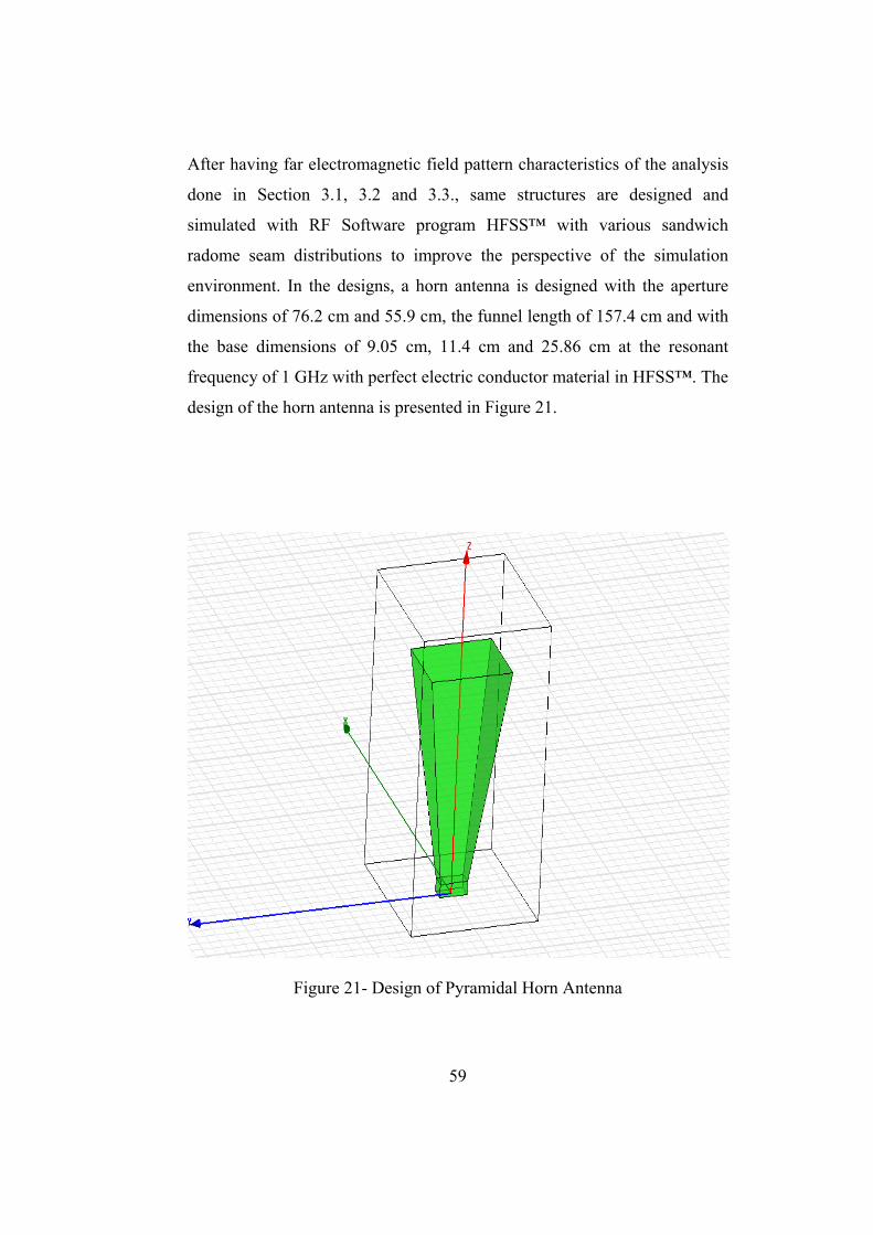
59
After having far electromagnetic field pattern characteristics of the analysis
done in Section 3.1, 3.2 and 3.3., same structures are designed and
simulated with RF Software program HFSS™ with various sandwich
radome seam distributions to improve the perspective of the simulation
environment. In the designs, a horn antenna is designed with the aperture
dimensions of 76.2 cm and 55.9 cm, the funnel length of 157.4 cm and with
the base dimensions of 9.05 cm, 11.4 cm and 25.86 cm at the resonant
frequency of 1 GHz with perfect electric conductor material in HFSS™. The
design of the horn antenna is presented in Figure 21.
Figure 21- Design of Pyramidal Horn Antenna

60
Before inserting the sandwich radome seams in the near field of the horn
antenna, original antenna field pattern characteristics is obtained to observe
the effect of the scattering effect of the sandwich radome seams on the total
far electromagnetic field pattern. The designed horn antenna’s original 3D
Polar E-Field Pattern Characteristics is given in Figure 22.
Figure 22 – 3D Polar Plot of the Horn Antenna E-Field Pattern
The following 3D Rectangular E-Field pattern is obtained as in Figure 23.
This figure clearly shows the level of side lobes on the φ plane.

61
Figure 23 - 3D Rectangular Plot of the Antenna E-Field Pattern
Figure 24 represents antenna’s 2D total E-Field radiation characteristics on
the principal planes.
Figure 24- 2D Total E-Field Radiation Characteristics of the Antenna on Principal Planes

62
In Figure 24 red line represents the E-plane ( / 2φ π= ) characteristics and
blue line represents H-plane ( 0φ = ) characteristics. As seen in the figure
side lobes are in the H-plane ( 0φ = ). Major lobe has the same pattern
characteristics both for the E-plane ( / 2φ π= ) and H-plane ( 0φ = ).
After having the original antenna far electromagnetic field pattern
characteristics, the next step is the obtaining the total far electromagnetic
field characteristics which is the combination of original antenna
electromagnetic field and scattering field of sandwich radome seams. The
step of obtaining the total far electromagnetic field pattern characteristics of
the antenna and sandwich radome seams is partitioned into subsets to
examine scattering effect of the seams on the original antenna field clearly.
These subsets are inserting single horizontal sandwich radome seam, cross-
examining scattering effect of the seam polarization with respect to the
antenna aperture by changing the polarization of the sandwich radome seam
and finally finding the total far electromagnetic E-Field pattern
characteristics of arbitrary distributed sandwich radome seams and the
antenna.
To examine the effect of the first subset in HFSS™ with the previously
designed horn antenna, following geometry is constituted as presented in
Figure 25. Horizontal dielectric seam which is made of Silicon Dioxide with
the dimensions as 4,8 λ length and 0,2 λ diameter is placed at a distance of
6λ from the aperture as shown in figure.

63
Figure 25- Placement of 4,8 λ Length and 0,2 λ Diameter Horizontal Sandwich Radome Seam at 6λ Distance to the Horn Antenna
With this geometry, 3D Polar E-Field pattern in Figure 26 is obtained. With
the effect of scattering from the seam structure there are newly generated
side lobes in the field pattern while compared with the pure horn antenna
polar E- Field Pattern given in Figure 22.

64
Figure 26 - 3D Polar Plot of the Total E-Field Pattern of the 4,8 λ Length and 0,2 λ Diameter Horizontal Sandwich Radome Seam Placed at
6λ Distance to the Antenna
To present the effect of scattering on the side lobes, following 3D
Rectangular E-Field Pattern characteristic is obtained as given in Figure 27.
It is observed that the seam leads to increase the side lobe levels and newly
generated side lobes are occurred in the total far electromagnetic E-field
pattern characteristics.

65
Figure 27 - 3D Rectangular Plot E-Field Pattern of the 4,8 λ Length and 0,2 λ Diameter Horizontal Sandwich Radome Seam Placed at 6λ Distance to
the Antenna
Figure 28 represents 2D Total E-Field radiation characteristics of the horn
antenna and horizontal sandwich radome seam on the principal planes.
Figure 28 - 2D Total E-Field Radiation Characteristics of 4,8 λ Length and 0,2 λ Diameter Horizontal Sandwich Radome Seam Placed at 6λ Distance
to the Antenna

66
In Figure 28 red line represents the E-plane ( / 2φ π= ) characteristics and
blue line represents H-plane ( 0φ = ) characteristics of total electric field. As
seen in the figure newly generated side lobes are occurred on the H-plane
( 0φ = ) with the effect of horizontal sandwich radome seam in the near field
of the horn antenna.
The next analysis is related with the effect of the polarization of the
sandwich radome seam on the total far electromagnetic field characteristics.
To analyse this effect following design in HFSS™ is constructed as
presented in Figure 29. 4,8 λ Length and 0,2 λ Diameter dielectric seam
structure is placed on the perpendicular direction in front of the antenna as
presented in the figure. The nearest distance between the cylinder and the
antenna aperture is kept 6λ as in the horizontal sandwich radome seam
distribution case.
Figure 29- Placement of 4,8 λ Length and 0,2 λ Diameter Perpendicular Sandwich Radome Seam at 6λ Distance to the Antenna

67
With this distribution of the dielectric seam in the near field of the antenna
following far electromagnetic field pattern characteristics are obtained in
Figure 30, Figure 31 and Figure 32.
Figure 30 - 3D Polar Plot of the E-Field Pattern with 4,8 λ Length and 0,2 λ Diameter Perpendicular Sandwich Radome Seam in the Near Field of the
Antenna

68
Figure 31 - 3D Rectangular Plot of the E-Field Pattern of the 4,8 λ Length and 0,2 λ Diameter Perpendicular Sandwich Radome Seam and the
Antenna
Figure 32- 2D Total E-Field Radiation Characteristics of 4,8 λ Length and 0,2 λ Diameter Perpendicular Sandwich Radome Seam Placed at
6λ Distance to the Antenna

69
Figure 32 shows 2D radiation pattern characteristics of perpendicular
sandwich radome seam and the horn antenna. In this figure red line
represents the E-plane ( / 2φ π= ) characteristics and blue line represents H-
plane ( 0φ = ) characteristics of total electric field.
As presented in Figures 30, 31 and 32, scattering effect of dielectric
perpendicular seam and the antenna is lower when compared with the
characteristics of antenna and dielectric horizontal sandwich radome seam
geometry in Figures 26, 27 and 28. This phenomenon can be explained as
the blocking area degradation of the aperture in the near field when it is
placed in perpendicular polarization on to the aperture plane. Actually, it is
an expected result of the analysis done in Section 3.2. Since the incidence
angle is 90oψ = for perpendicular directed seam in front of the antenna,
cosψ expression in the TEScatteredE equation leads to zero in the scattered
electromagnetic field expression. Therefore, far electromagnetic field
pattern is constituted directly from the antenna original field with this
distribution.
Finally, placement of 7 sandwich radome seams which have dimensions as
4,8 λ length and 0,2 λ diameter is simulated. The angle of inclination of
the sandwich radome seams are taken 030ψ = for 6 seams and 00ψ = for
the horizontal seam such that the other 6 seams are attached the horizontal
sandwich radome seam. The distances from the aperture are taken as 6λ as
in the previous simulations.

70
Figure 33- Multi Numbered Distribution of 4,8 λ Length and 0,2 λ Diameter Sandwich Radome Seams Placed at 6λ Distance to the Antenna
Figure 33 presents multi numbered seam distribution defined in the above
paragraph. As clearly presented in the figure, the distribution of sandwich
radome seams constitutes a typical framework of a sandwich type radome.
With this design of antenna and sandwich radome seams, following total far
electromagnetic E-Field pattern characteristics are obtained as given in
Figure 34 and Figure 35.

71
Figure 34 - 3D Polar Plot of the E-Field of the Distributed 4,8 λ Length and 0,2 λ Diameter Sandwich Radome Seams Placed at 6λ Distance to the
Antenna
Figure 35 - 2D Total E-Field Radiation Characteristics of Distributed 4,8 λ Length and 0,2 λ Diameter Sandwich Radome Seams Placed at
6λ Distance to the Antenna

72
Figure 35 represents 2D Total E-Field radiation characteristics of distributed
sandwich radome seams and the antenna. In this figure red line represents
the E-plane ( / 2φ π= ) characteristics and blue line represents H-plane
( 0φ = ) characteristics of total electric field. Distortion of field pattern
characteristics on both planes is clearly presented in this figure.
Figure 34 and Figure 35 show that there are newly generated high powered
side lobes occurred in the field pattern with the effect of distributed
sandwich radome seams in the near field of the antenna. This HFSS™ result
is well adjusted with the analysis done in section 3.3. This resemblance is
shown in Figure 20 and Figure 35. In both figures, result of the placement of
7 sandwich radome seams which have dimensions as 4,8 λ length and 0,2
λ diameter such that the angle of inclination of the incident antenna field
to the sandwich radome seams is taken 030ψ = for 6 seams and 00ψ = for
the horizontal seam at 6λ distances from the aperture is presented. As seen
from the characteristics obtained in Figures 20, 34 and 35 distributed
sandwich radome seams change the shape of the main beam of the antenna
original field in the pattern and lead high powered side lobes on the E-plane
especially for the angles 30θ = and 70θ = respectively.
To sum up, multi numbered sandwich radome seams positioned in the near
field of the antenna leads to important distortion on the antenna original
field pattern as expected. In Chapter 4, ways to decrease the distortion via
the effect of the sandwich radome framework structure is discussed and two
different design methods are proposed to solve the problem.

73
CHAPTER 4
ENHANCING ELECTROMAGNETIC
TRANSPARENCY OF SANDWICH TYPE
RADOMES
4.1 Factors Effecting Electromagnetic Performance of the
Structure
Radomes are very crucial to protect the antennas from harsh weather
conditions and to sustain the operational performance of these systems for a
long period of time. However, if the radomes are not appropriately designed,
they lead important distortions on the original antenna signal. This chapter
is totally devoted to discuss the ways of enhancing electromagnetic
performance of the antenna and sandwich type radome systems.
As mentioned before, panels of the sandwich radome systems are
technologically fabricated using honeycomb polyurethane materials such
that insertion loss due to panels in sandwich radomes is much less than 0,1
dB. However, the seams that connect these electromagnetically transparent
panels lead 4 to 100 times greater insertion and scattering losses when
compared with the panels. This is the reason of devoting this thesis work on
74
analyzing and enhancing electromagnetic transparency of the sandwich
radome flange framework.
Enhancing electromagnetic transparency methods of sandwich radomes can
be grouped in two different parts. The first group is the arranging the
geometric positions of the sandwich radome seams. The next one is adding
conducting materials in the dielectric seams to decrease the capacitance of
the structure by tuning.
4.2 Importance of the Distance of the Seam Structure to the
Antenna Aperture
Seam blocking effect increases in the near field when the distance between
the aperture and the seam structure decreases. This blocking leads high
levels of scattering on the incident electromagnetic field generated by the
antenna. Level of scattering effect by changing the distance of the seam
from the aperture is analyzed by the following simulation in HFSS™. 4,8
λ length and 0,2 λ diameter sandwich radome seam material made of
silicon dioxide is placed in front of the aperture of the antenna with different
distances. First one is placed at a 3λ wavelength distance and the other one
is placed at a 10.7λ wavelength distance from the aperture. The Figure 36
shows the placement of horizontal dielectric seam in the near field of the
antenna at a distance of 3λ from the aperture. The Figure 37 presents the
placement of same horizontal dielectric seam at a distance of 10.7λ from
the aperture of the antenna.

75
Figure 36 - 4,8 λ Length and 0,2 λ Diameter Sandwich Radome Seam Placed at 3λ Distance to the Aperture
Figure 37 - 4,8 λ Length and 0,2 λ Diameter Sandwich Radome Seam Placed at 10.7λ Distance to the Aperture

76
Far electromagnetic field distance from the antenna where the Fraunhofer
region starts can be calculated with:
22dDλ
= (4.1)
where D is the minimum far electromagnetic field distance from the antenna
aperture, d is the aperture hypotenuse and λ is the wavelength. Frequency
of the antenna is 1 GHz, the aperture dimensions are 76.2 and 55.9 cm
respectively as in the previous analyzes. From the equation the distance D is
around 18λ . Therefore, 10.7 wavelength distant sandwich radome seam is
in Fresnel region as a realistic case.
Following 3D Rectangular E-Field characteristics is obtained with the
horizontal placement of 3λ wavelength distant sandwich radome seam in
front of the aperture as presented in Figure 38. Figure 39 shows total E-field
pattern characteristics of horizontally placed 10.7λ distant sandwich
radome seam. Figure 40 shows the total polar E-Field plot of 3λ distant
sandwich radome seam in front of the aperture. Figure 41 shows the total
polar E-Field plot 10.7 wavelength distant sandwich radome seam in front
of the aperture.
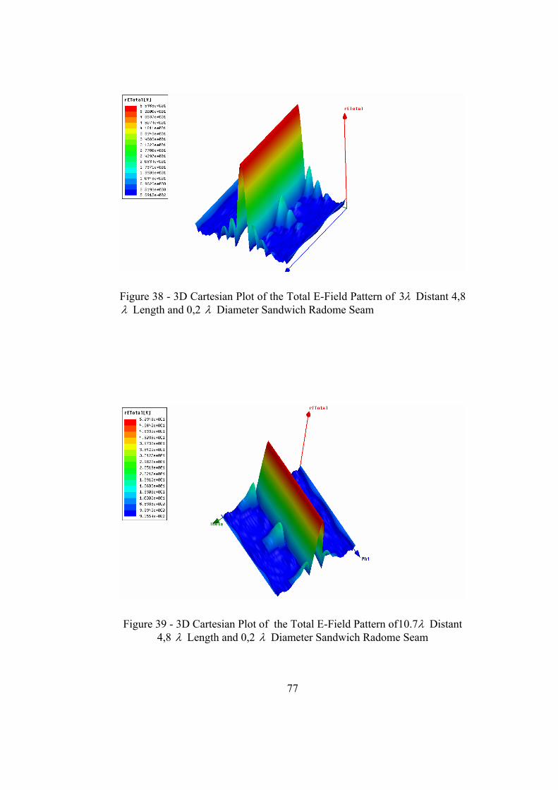
77
Figure 38 - 3D Cartesian Plot of the Total E-Field Pattern of 3λ Distant 4,8 λ Length and 0,2 λ Diameter Sandwich Radome Seam
Figure 39 - 3D Cartesian Plot of the Total E-Field Pattern of10.7λ Distant 4,8 λ Length and 0,2 λ Diameter Sandwich Radome Seam

78
Figure 40 - Polar Plot of the Total E-Field Pattern of 3λ Distant 4,8 λ Length and 0,2 λ Diameter Sandwich Radome Seam
Figure 41 - Polar Plot of the Total E-Field Pattern of 10.7λ Distant 4,8 λ Length and 0,2 λ Diameter Sandwich Radome Seam

79
It should be noted that scattering effect with near sandwich radome seam is
higher than the far sandwich radome seam as expected. Design with 3λ
distant sandwich radome seam has newly generated side lobes which are
formed by the scattering effect of sandwich radome seam as given in
Figures 38 and 40. However, the design with 10.7λ distant sandwich
radome seam has no newly generated side lobes and the pattern is quite
similar to the original antenna field pattern characteristics as given in
Figures 39 and 41. Therefore, the design of sandwich radome seams should
be such that the distance of the seams from the aperture of the antenna
should be kept as far as possible. However, it should always be kept in mind
that this means a larger area for the antenna system, higher cost for
production and installation. Having these constraints the distance of the
seams from the aperture should be designed such that the effect of scattering
could be adoptable.
4.3 Enhancing Electromagnetic Transparency by Quasi-
Random Geometric Distribution of Seams
In the section 4.2, the effect of the distance of the sandwich radome seam on
the electromagnetic transparency of the structure is expressed. In this
section a way of enhancing electromagnetic transparency without changing
the distance of the seams from the antenna structure is presented. This
design method is called Geometric Randomization. It is also known as
quasi-random geometric distribution of seams [12]. Enhancing
electromagnetic transparency can be obtained by minimizing the total
scattered field which is composed of the scattered field of each sandwich
radome seam forming the whole framework of the sandwich radome. As
analyzed in previous chapter total scattered field is the vector summation of

80
the scattered electromagnetic field of each sandwich radome seam.
Therefore, if the seams are distributed in a randomized way, in other words
sandwich radome panels are designed such that the geometry of each panel
is designed in a different type as given in Figure 42, constituted total
scattered electromagnetic field with the vector summation of the scattered
electromagnetic field of each panel seam will be with relatively small
coefficients while compared with the relatively parallel distributed seam
structured sandwich radome seams. Therefore, new side lobe level
generations or increased side lobe levels can be prevented with this method.
Figure 42 – 18.9 Meter Diameter Sandwich Radome Panels and Panel Framework Geometry [3]

81
To express the importance of Geometrical Randomisation following
simulation work is done in HFSS™. In this work, same number of seams is
placed in front of the antenna at relatively same distance. The first design is
very similar to the orange-peel type designed radome framework defined in
Chapter 2. In this design, framework geometry is composed of parallel
elements in azimuth and elevation. In the second design, the framework
elements are placed in a totally randomized geometry to show the effect of
Geometrical Randomization clearly. Figure 43 shows the design with
orange-peel type radome framework structure.
Figure 43 – Orange-Peel Radome Framework Design with 2,8 λ Length and 0,2 λ Diameter 12 Seams Placed at 6λ Distance to the Antenna

82
Figure 44 shows the 3D polar plot of total far electromagnetic E-Field
Pattern with orange-peel type designed sandwich radome seams in front of
the antenna. As can be seen clearly from the figure, the pattern
characteristics highly distorted with effect of cumulative scattering effect of
each seam forming the framework. Shape of the main beam is highly
distorted as presented. Moreover many new side lobes are generated with
the effect of scattering.
Figure 44 - 3D Polar Plot of Total E-Field Pattern of Orange-Peel Type Designed Sandwich Radome Framework with 2,8 λ Length and 0,2 λ
Diameter 12 Seams Placed at 6λ Distance to the Antenna

83
Figure 45 - 3D Rectangular Plot of the E-Field Pattern Characteristics of Orange-Peel Type Designed Sandwich Radome Framework with 2,8 λ Length and 0,2 λ Diameter 12 Seams Placed at 6λ Distance to the Antenna
Figure 45 shows 3D Rectangular Plot of the Total E-Field Pattern of the
orange-peel type designed Sandwich Radome framework in front of the
antenna to clearly present the effect of cumulative scattering of each
sandwich radome seam structure. The occurrence of high numbered side
lobe levels and broadened main beam of the antenna is clearly presented in
the figure.
After having the characteristics of parallel designed sandwich radome seam
framework geometry, to show the importance of randomized distribution of
sandwich radome seams following design is constructed in HFSS™ as given
in Figure 46.

84
Figure 46 – Randomized Distribution of 2,8 λ Length and 0,2 λ Diameter 12 Seams Placed at Approximately 6λ Distance In Front of the Antenna
Figure 47 shows the 3D Polar Plot of the total E-Field pattern characteristics
of randomized distribution of seams in front of the antenna. When compared
with the characteristics obtained with orange-peel type design in Figure 44,
distortion of the antenna signal in Figure 47 with minimized cumulative
scattering effect of each random distributed sandwich radome seam is quite
less as expected. This figure shows the importance preventing parallel
structures in the framework clearly.

85
Figure 47 - 3D Polar E-Field Pattern of Random Distributed 2,8 λ Length and 0,2 λ Diameter 12 Seams Placed at Approximately 6λ Distance In
Front of the Antenna
Figure 48- 3D Rectangular Total E-Field Pattern of Random Distributed 2,8 λ Length and 0,2 λ Diameter 12 Seams Placed at Approximately 6λ
Distance In Front of the Antenna

86
Figure 48 shows 3D Rectangular Plot of the Total E-Field Pattern of the
Randomized Distribution of the Sandwich Radome Seams in front of the
antenna. When compared with the characteristics in Figure 45, lower
number of newly generated side lobes and sharper main beam are the
important differences between two characteristics
4.4 Electromagnetic Transparency Enhancement by Tuning
the Seams in Sandwich Type Radomes
In sandwich type radomes the framework materials are usually composed of
dielectric materials such as polyamide foams, silicon dioxide, silicon nitrate
etc. In these dielectric structures with the effect of incident antenna field,
parallel and perpendicular polarization currents occur. These currents play
the main role on the electromagnetic scattering effect of the framework
structure of the sandwich type radomes. Enhancing electromagnetic
transparency can be achieved if these polarization currents can be decreased.
To decrease these polarization currents inside the framework structure of the
sandwich radome, perfectly conducting materials are inserted inside the
seam.
4.4.1 Tuning the Seams in Sandwich Type Radomes
It is known that perfectly conducting materials directly scatter the antenna
incident electromagnetic signal such that IFR (induced field ratio) is -1.
Therefore, even in the Metal Space Frame Radomes which are the most
common radomes in the world, only the framework structure is composed
conducting materials such as Aluminum. However in the Sandwich Radome
case, the perfectly conducting materials are inserted in the dielectric
framework to decrease high capacitance of the structure. It can be viewed as

87
inserting an inductor to the highly capacitive circuit to tune in. Inserting
perfect electric conductors inside the radome seam is named as Tuning the
Radome. Inserting these thin perfectly conducting materials inside the
seams, decrease the polarization currents inside the framework structure.
This degradation increases the electromagnetic transparency of the seams of
the Sandwich Radome. With this design solution it is possible to design
sandwich type radomes for antennas which operate at high frequencies.
4.4.2 Effect of Tuning the Seams in Sandwich Type
Radomes
The effect of inserting perfect conductors inside the dielectric framework
structure of the sandwich radome is emphasized by the following design in
HFSS™. First, one horizontal dielectric cylinder which has a radius of 7 cm
made of silicon dioxide (relative permittivity is 4 and relative permeability
is 1) is inserted in front of the horn antenna near field at a distance of 5λ
distance from the horn as seen in the figure 49. In this simulation the radius
of the dielectric seam is increased specifically to emphasize the tuning effect
in the next step.

88
Figure 49 – Horizontal Silicon Dioxide Cylinder Seam with 4,8 λ Length and 0,47λ Diameter Placed at 5λ Distance to the Horn Antenna
With this configuration following far electromagnetic E-field patterns
obtained as given in Figures 50, 51 and 52.
Figure 50 - 3D Polar Total E-Field of the Horizontal Silicon Dioxide Seam with 4,8 λ Length and 0,47λ Diameter Placed at 5λ Distance to the Horn
Antenna

89
Figure 51 - 3D Rectangular Total E-Field of the Horizontal Silicon Dioxide Seam with 4,8 λ Length and 0,47λ Diameter Placed at 5λ Distance to the
Horn Antenna
Figure 52 - 2D Total E-Field of the Horizontal Silicon Dioxide Seam with 4,8 λ Length and 0,47λ Diameter Placed at 5λ Distance to the Horn
Antenna
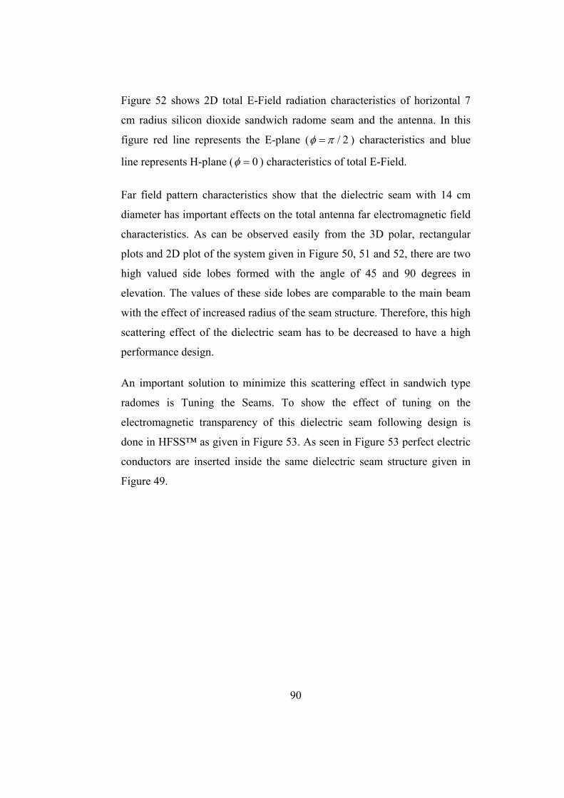
90
Figure 52 shows 2D total E-Field radiation characteristics of horizontal 7
cm radius silicon dioxide sandwich radome seam and the antenna. In this
figure red line represents the E-plane ( / 2φ π= ) characteristics and blue
line represents H-plane ( 0φ = ) characteristics of total E-Field.
Far field pattern characteristics show that the dielectric seam with 14 cm
diameter has important effects on the total antenna far electromagnetic field
characteristics. As can be observed easily from the 3D polar, rectangular
plots and 2D plot of the system given in Figure 50, 51 and 52, there are two
high valued side lobes formed with the angle of 45 and 90 degrees in
elevation. The values of these side lobes are comparable to the main beam
with the effect of increased radius of the seam structure. Therefore, this high
scattering effect of the dielectric seam has to be decreased to have a high
performance design.
An important solution to minimize this scattering effect in sandwich type
radomes is Tuning the Seams. To show the effect of tuning on the
electromagnetic transparency of this dielectric seam following design is
done in HFSS™ as given in Figure 53. As seen in Figure 53 perfect electric
conductors are inserted inside the same dielectric seam structure given in
Figure 49.
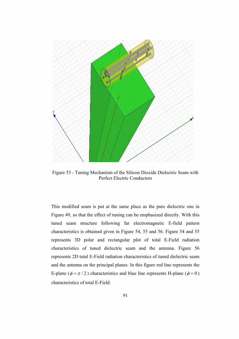
91
Figure 53 - Tuning Mechanism of the Silicon Dioxide Dielectric Seam with Perfect Electric Conductors
This modified seam is put at the same place as the pure dielectric one in
Figure 49, so that the effect of tuning can be emphasized directly. With this
tuned seam structure following far electromagnetic E-field pattern
characteristics is obtained given in Figure 54, 55 and 56. Figure 54 and 55
represents 3D polar and rectangular plot of total E-Field radiation
characteristics of tuned dielectric seam and the antenna. Figure 56
represents 2D total E-Field radiation characteristics of tuned dielectric seam
and the antenna on the principal planes. In this figure red line represents the
E-plane ( / 2φ π= ) characteristics and blue line represents H-plane ( 0φ = )
characteristics of total E-Field.
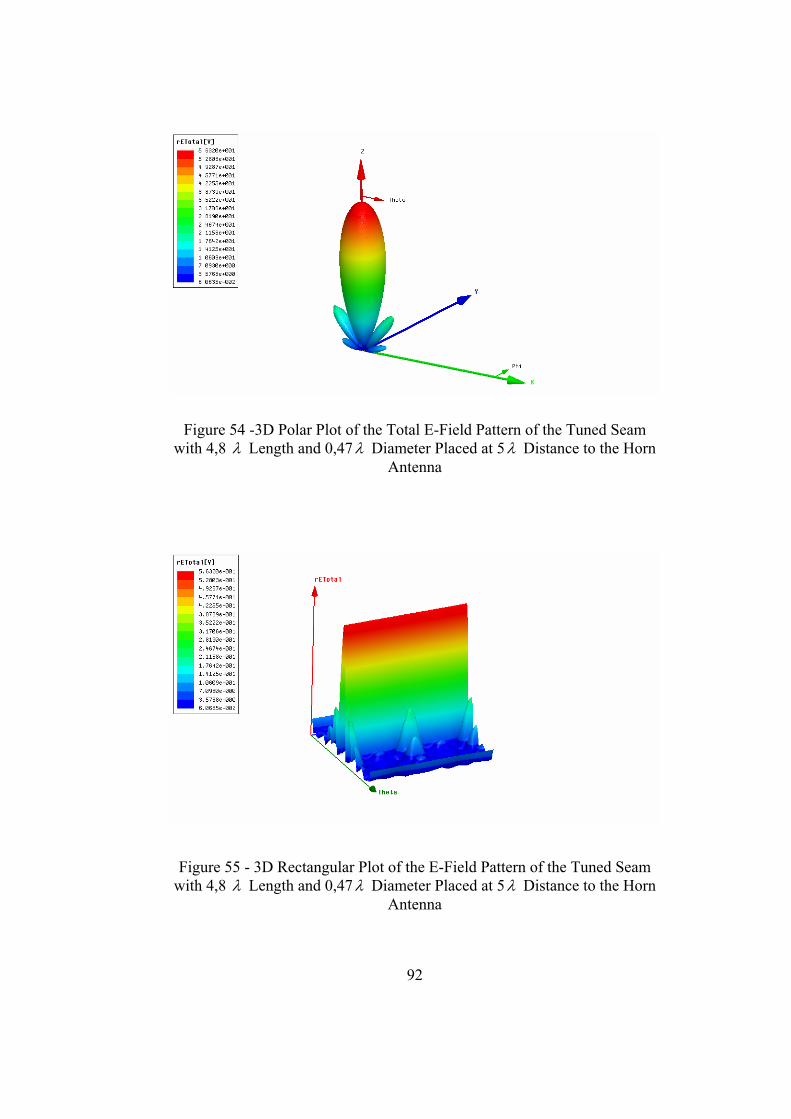
92
Figure 54 -3D Polar Plot of the Total E-Field Pattern of the Tuned Seam with 4,8 λ Length and 0,47λ Diameter Placed at 5λ Distance to the Horn
Antenna
Figure 55 - 3D Rectangular Plot of the E-Field Pattern of the Tuned Seam with 4,8 λ Length and 0,47λ Diameter Placed at 5λ Distance to the Horn
Antenna
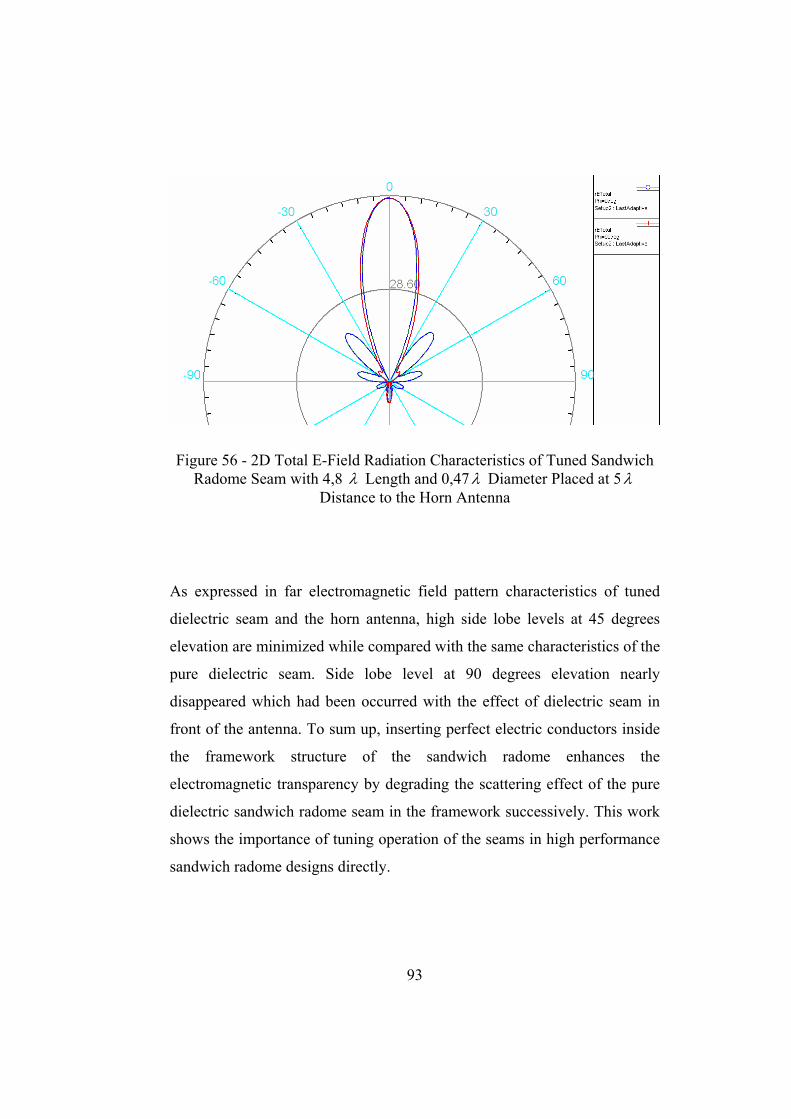
93
Figure 56 - 2D Total E-Field Radiation Characteristics of Tuned Sandwich Radome Seam with 4,8 λ Length and 0,47λ Diameter Placed at 5λ
Distance to the Horn Antenna
As expressed in far electromagnetic field pattern characteristics of tuned
dielectric seam and the horn antenna, high side lobe levels at 45 degrees
elevation are minimized while compared with the same characteristics of the
pure dielectric seam. Side lobe level at 90 degrees elevation nearly
disappeared which had been occurred with the effect of dielectric seam in
front of the antenna. To sum up, inserting perfect electric conductors inside
the framework structure of the sandwich radome enhances the
electromagnetic transparency by degrading the scattering effect of the pure
dielectric sandwich radome seam in the framework successively. This work
shows the importance of tuning operation of the seams in high performance
sandwich radome designs directly.

94
CHAPTER 5
CONCLUSIONS
Sandwich radomes are the best solution for high performance, discrete
narrow band, large antenna systems to prevent them from harsh weather
conditions, to maintain required operational performance of the system for
long periods of time while having minimum effect on the electromagnetic
fields transmitted and received by the inside antenna systems. When
compared with other radome types investigated in this thesis, mechanical
and electromagnetic features of sandwich radomes put forth importance of
sandwich radome structures. Since sandwich radome panels are specifically
manufactured considering operating frequency of the antenna and insulation
need of environment, electromagnetic insertion loss is around 0.1 dB for
typical applications. However, transmission loss due to the framework of
the sandwich radome panels is around 0.4 dB up to 10 dB for a design
which only the constructional requirements are considered. Therefore,
electromagnetic analysis and enhancing electromagnetic transparency of the
framework structure of the sandwich radomes are very crucial for high
performance designs.
In this thesis, after the investigation of most common radome types
Sandwich Radomes are presented with their detailed features including
structural and electromagnetic properties. Electromagnetic scattering

95
analysis of the Sandwich Radome framework is done. In this analysis, as a
first step, scattering analysis of one dielectric cylinder seam is done. In the
analysis, pyramidal horn type antenna is used because of the well known
information on the near electromagnetic fields of the antenna. In fact the
analysis is applicable to all antenna systems with the knowledge of antenna
near electromagnetic field formulations. In the next step the analysis done
for one seam structure is generalized for arbitrary numbered distributed
seams with different angles with respect to the antenna. As a final step, total
far electromagnetic fields of the horn antenna and total electromagnetic
scattered fields by the framework structure of Sandwich Radomes are
combined to express the total antenna system far electromagnetic fields.
Finally, using Ansoft HFSS™ program electromagnetic field patterns of
antenna and framework structure of Sandwich Radomes are simulated with
various antenna and seam distributions. This analysis is done with
pyramidal horn type antenna as a case study which has a resonant frequency
of 1 GHz with the dimensions 76.2 cm ( 2.54λ ) and 55.9 cm (1.86λ ) at the
aperture, funnel length of 157.4 cm (5.24λ ) with base of the horn
dimensions of 9.05 cm ( 0.3λ ), 11.4 cm ( 0.38λ ) and 25.86 cm ( 0.862λ ) at
this resonant frequency. Seams are put at different angles and with different
polarizations with respect to the aperture of the antenna to generalize the
scattering effect of the seam structures on the antenna far electromagnetic
field patterns. Numerical experiment is repeated for the cases of various
number of seams in front of the antenna. Obtained results show the success
of electromagnetic scattering analysis.
In this thesis, there are two important design solutions suggested to enhance
electromagnetic transparency of the radome framework of the Sandwich
Radomes. The solutions are named as Geometrical Randomization and
Tuning the Seams. In Ansoft HFSS™, the effects of two design solutions
are expressed successively.

96
To show the importance of Geometrical Randomization, same length and
same number of seams are distributed randomly around the antenna at the
resonant frequency of 1 GHz in Ansoft HFSS™ design program. Then the
total scattering effect is compared with parallel distributed radome seam
structures as in the Orange-Peel Sandwich Radome Type around the same
antenna at the same frequency. The result shows that electromagnetic
transparency of radome seams is enhanced via increasing randomness
distribution of the seams as suggested. Simulations show that total scattering
effect of orange-peel type geometric distribution of seams is higher than the
randomized geometrical distribution of same number of seams.
Furthermore, structural investigation of orange-peel type geometry and
quasi-random type geometry of sandwich type radomes has shown that
quasi-random geometric distribution of the framework strengthens the
structure more than the orange-peel type geometric distribution of seams in
the framework. It should be kept mind that, while increasing the randomness
of the seams in quasi-random geometry it is important to keep total seam
length as low as possible. Because, if total seam length increase is not
controlled, it causes higher transmission loss due to the framework and this
will become an unwanted drawback. Moreover, it should always be
considered that producing and installing costs of the sandwich radome
panels increase by increasing randomness of the panels.
In this thesis work, a second solution for enhancing the transparency of
sandwich radomes is expressed and named as Tuning the Seams. This
solution broadens the usage of sandwich type radomes up to high
frequencies because of the minimization of the framework scattering fields
of the sandwich radomes. In this method perfect electric conductors are
inserted inside the seam structure. This composite structure enhances the
transparency of the framework because of the degradation of the
polarization currents inside the seam structure. Its effect on the scattering

97
field of the framework is shown via Ansoft HFSS™ simulations
successively.
As a future work, electromagnetic responses of different composite
materials constituting the sandwich radome panels and the panel framework
can be investigated. Finding the best frequency band of operation
information for different sandwich radome materials including the
framework and the panel structures will increase the importance of the
investigation. Moreover, as a future work insertion loss due to the panels
and the framework structure which is composed of dielectric and conducting
materials can be added to the scattering analysis in this thesis work.
Insertion loss occurrence by tuning the seams with conducting materials can
be investigated with this future work. Furthermore, investigation on the
mechanical properties including critical buckling speed and the safety factor
can be done for different sandwich radome materials for the framework and
the panels. Finally, all the investigations may be combined with cost
analysis of the materials constituting the sandwich radome structure itself
and the building operation difficulty with these specific materials put forth
economic and constructional manufacturability of the designs with
Sandwich Radomes.
98
REFERENCES
[1] Wikipedia, “Radome”, http://en.wikipedia.org/wiki/Radome, January18
th 2009, Last date accessed: March 2009
[2] Antennas For Communications, http://www.radome.net, January18 th
2009, Last date accessed: March 2009
[3] Essco Radomes, http://www.esscoradomes.com, January18 th 2009, Last
date accessed: March 2009
[4] Micris Radomes, http://www.micris.co.uk/radomes.php, January25 th
2009, Last date accessed: March 2009
[5] Radome Panel Transportation Preparation,
http://www.thecoolroom.org/news/RadomePieces_Crate.jpg, January25 th
2009, Last date accessed: March 2009
[6] Radome Panel Installation, http://www.radomes.com, January25 th
2009, Last date accessed: March 2009
[7] Wikipedia, “Insertion Loss”,
http://en.wikipedia.org/wiki/Insertion_loss, January25 th 2009, Last date
accessed: March 2009
[8] W.T.Rusch, J.A.Hansen, R.Mittra, C.A.Klein, “Forward scattering from
square cylinders in the resonance region with application to aperture
blockage.” IEEE Trans. Antenna Propaga.vol AP-24, no.2 pp-182-189, Mar.
1976

99
[9]EsscoRadomes,http://www.l3com.com/essco/resources/ifrdefinition.html,
January 26 th 2009, Last date accessed: March 2009
[10] Essco Radomes, Hydrophobic Coating,
http://www.l3com.com/essco/resources/hydrophobiccoating.html, January
26 th 2009, Last date accessed: March 2009
[11] Saint - Gobain Performance Plastics “Radome Installations_polyester”
Aselsan Inc. Proposal 162-1561 D May 2004
[12] Reuven Shavit, Adam P.Smolski, Eric Michielssen and Raj Mittra
“Scattering Analysis of High Performance Large Sandwich Radomes” IEEE
Transaction on Antennas and Propagation, Vol.40, No.2 February 1992
[13] Saint-Gobain Flight Structures, “Sandwich Radome Types” ,
http://www.radome.com, January 31 th 2009, Last date accessed: March
2009
[14] V.J. Dicaudo “Determining Optimum C-Sandwich Radome Thickness
by Means of Smith Chart”, IEEE Transections on Antennas and
Propagation, pp 822-823, November 1967
[15] I. D. King “Application of On-Surface Radiation Condition to
Electromagnetic Scattering by Conducting Strip”, IEEE Electronic Letters
Vol.25 No.1 5th January 1989
[16] Doris I. WU, Motohisa Kanda, “Comparison of Theoretical and
Experimental Data for the Near Field of an Open-Ended Rectangular
Waveguide” IEEE Transactions on Electromagnetic Compatibility, Vol.31
No.4. November 1989
[17] R.E.Collin, “Antennas and Radiowave Propagation”, McGraw-Hill
International Editions 3rd printing 1988.

100
[18] George T. Ruck, Donald E.Barrick, William D. Stuart, Clarence K.
Krichbaum, “Radar Cross Section Handbook”, Plenum Press New York
1970.
[19] Plamen I. Dankov, Vesselin N. Peshlov, Mario Gachev,“ Modeling and
Characterization of Multilayer Antenna Radomes with Anisotropic
Materials”, University of Sofia St. Klimends Ohridsky

101
APPENDIX
Horn Antenna Far Electromagnetic Fields
Far electromagnetic fields of the horn antenna are determined from the
aperture electromagnetic fields.
The dominant mode of the horn antenna is 10TE mode. Let’s define the
antenna aperture dimensions as “a” and “b” relatively .Then the typical
aperture fields are defined as:
0 cos( ) j zy
xE E e aa
βπ −= (1)
0 0 cos( ) j z
xxH E Y e a
aβπ −= −
(2)
where
2 2( )okaπβ = − (3)
/2 /2
/2 /2
( , ) yx
b ajk yjk x
ab a
f x y E e e dxdy− −
= ∫ ∫ (4)
where aE is the aperture E-Field
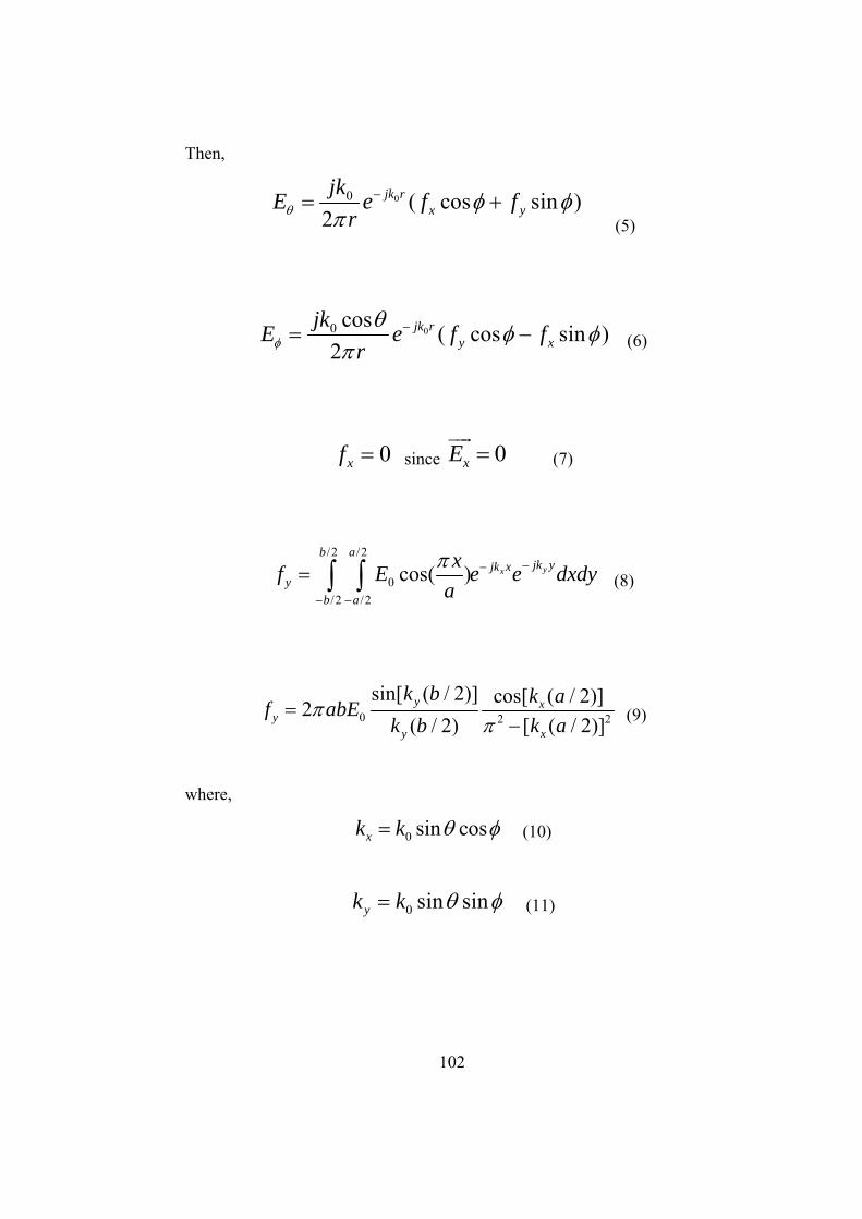
102
Then,
00 ( cos sin )2
jk rx y
jkE e f frθ φ φ
π−= +
(5)
00 cos ( cos sin )2
jk ry x
jkE e f frφθ φ φ
π−= − (6)
0xf = since 0xE = (7)
/2 /2
0/2 /2
cos( ) yx
b ajk yjk x
yb a
xf E e e dxdyaπ −−
− −
= ∫ ∫ (8)
0 2 2
sin[ ( / 2)] cos[ ( / 2)]2( / 2) [ ( / 2)]y x
yy x
k b k af abEk b k a
ππ
=− (9)
where,
0 sin cosxk k θ φ= (10)
0 sin sinyk k θ φ= (11)

103
{ }00
00
0
0
2 20
0 0
2 20 0
sin( sin sin )2[ sin
sin sin2
cos( sin cos )2[ ]
4( sin cos )2
sin( sin sin ) cos( sin cos )2 2(cos cos )[ ] ]
sin sin 4( sin cos )2 2
jk rANTENNA
bkjkE E abe br k
akaak
b ak kab ak k
θ
φ
θ φφ
θ φ
θ φ
π θ φ
θ φ θ φθ φ
θ φ π θ φ
−=
−
+−
(12)