electrolytic capacitors - panasonic...conductive polymer hybrid aluminum electrolytic capacitors/za...
TRANSCRIPT
(Conductive Polymer Hybrid Aluminum Electrolytic Capacitors)
CATALOG
Electrolytic Capacitors
2014
industrial.panasonic.com/ww/2014.6

.
Design and specifi cations are each subject to change without notice. Ask factory for the current technical specifi cations before purchase and/or use.Should a safety concern arise regarding this product, please be sure to contact us immediately.
Conductive Polymer Hybrid Aluminum Electrolytic Capacitors/ZA
– EEE-2 –
Capacitance (μF)
Rated Voltage Mark
Series identification
Lot number
Negative polarity marking (–)
A±0.2
W
( ) Reference size
L
0D±
0.5
H
B±
0.2
(I)
K
(P)
(I)
+
–0.3 max.
Pressure Relief (010 and larger)
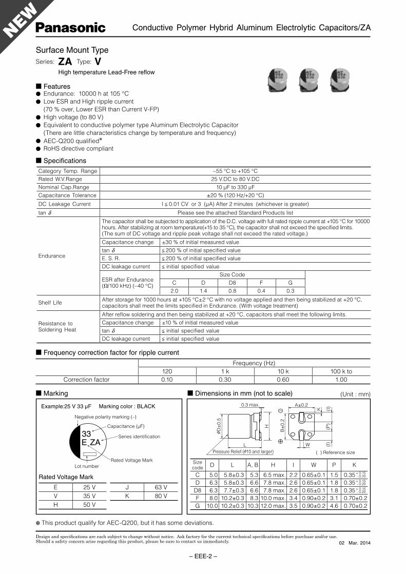
Features Endurance: 10000 h at 105 °C
Low ESR and High ripple current
(70 % over, Lower ESR than Current V-FP)
High voltage (to 80 V)
Equivalent to conductive polymer type Aluminum Electrolytic Capacitor
(There are little characteristics change by temperature and frequency)
AEC-Q200 qualifi ed
RoHS directive compliant
Surface Mount Type
Series: ZA Type: V High temperature Lead-Free refl ow
Specifi cations
Category Temp. Range –55 °C to +105 °C
Rated W.V.Range 25 V.DC to 80 V.DC
Nominal Cap.Range 10 μF to 330 μF
Capacitance Tolerance ±20 % (120 Hz/+20 °C)
DC Leakage Cur rent I < 0.01 CV or 3 (μA) After 2 minutes (whichever is greater)
tan d Please see the attached Standard Products list
Endurance
The capacitor shall be subjected to application of the D.C. voltage with full rated ripple current at +105 °C for 10000 hours. After stabilizing at room temperature(+15 to 35 °C), the capacitor shall not exceed the specifi ed limits.(The sum of DC voltage and ripple peak voltage shall not exceed the rated voltage.)
Capacitance change ±30 % of initial measured value
tan d < 200 % of initial specifi ed value
E. S. R. < 200 % of initial specifi ed value
DC leakage current < initial specifi ed value
ESR after Endurance(Ω/100 kHz) (–40 °C)
Size Code
C D D8 F G
2.0 1.4 0.8 0.4 0.3
Shelf LifeAfter storage for 1000 hours at +105 °C±2 °C with no voltage applied and then being stabilized at +20 °C, capacitors shall meet the limits specifi ed in Endurance. (With voltage treatment)
Resistance toSoldering Heat
After refl ow soldering and then being stabilized at +20 °C, capacitors shall meet the following limits.
Capacitance change ±10 % of initial measured value
tan d < initial specifi ed value
DC leakage current < initial specifi ed value
Di men sions in mm (not to scale) Marking
Example:25 V 33 μF Marking color : BLACK
Rated Voltage Mark
Frequency (Hz)
120 1 k 10 k 100 k to
Correction factor 0.10 0.30 0.60 1.00
Frequency correction factor for ripple current
Sizecode
D L A, B H I W P K
C 5.0 5.8±0.3 5.3 6.5 max. 2.2 0.65±0.1 1.5 0.35 - 0.20
D 6.3 5.8±0.3 6.6 7.8 max. 2.6 0.65±0.1 1.8 0.35 - 0.20
D8 6.3 7.7±0.3 6.6 7.8 max. 2.6 0.65±0.1 1.8 0.35 - 0.20
F 8.0 10.2±0.3 8.3 10.0 max. 3.4 0.90±0.2 3.1 0.70±0.2
G 10.0 10.2±0.3 10.3 12.0 max. 3.5 0.90±0.2 4.6 0.70±0.2
+ 0.15
+ 0.15
+ 0.15E 25 V
V 35 V
H 50 V
J 63 V
K 80 V
(Unit : mm)
This product qualify for AEC-Q200, but it has some deviations.
02 Mar. 2014
Design and specifi cations are each subject to change without notice. Ask factory for the current technical specifi cations before purchase and/or use.Should a safety concern arise regarding this product, please be sure to contact us immediately.
Conductive Polymer Hybrid Aluminum Electrolytic Capacitors/ZA
– EEE-3 –
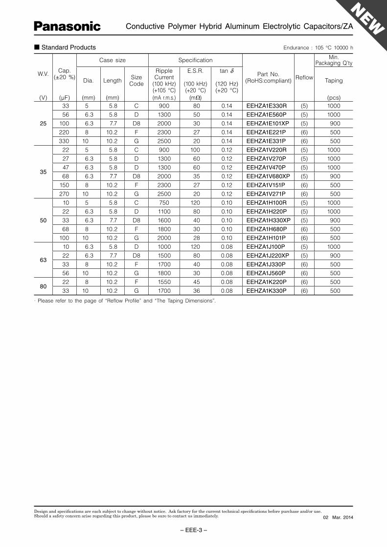
Standard Products
· Please refer to the page of “Refl ow Profi le” and “The Taping Dimensions”.
Endurance : 105 °C 10000 h
W.V.Cap.
(±20 %)
Case size Specifi cation
Part No.(RoHS:compliant)
Refl ow
Min.Packaging Q'ty
Dia. LengthSize
Code
RippleCurrent
(100 kHz)(+105 °C)
E.S.R.
(100 kHz)(+20 °C)
tan d
(120 Hz)(+20 °C)
Taping
(V) (μF) (mm) (mm) (mA r.m.s.) (mΩ) (pcs)
25
33 5 5.8 C 900 80 0.14 EEHZA1E330R (5) 1000
56 6.3 5.8 D 1300 50 0.14 EEHZA1E560P (5) 1000
100 6.3 7.7 D8 2000 30 0.14 EEHZA1E101XP (5) 900
220 8 10.2 F 2300 27 0.14 EEHZA1E221P (6) 500
330 10 10.2 G 2500 20 0.14 EEHZA1E331P (6) 500
35
22 5 5.8 C 900 100 0.12 EEHZA1V220R (5) 1000
27 6.3 5.8 D 1300 60 0.12 EEHZA1V270P (5) 1000
47 6.3 5.8 D 1300 60 0.12 EEHZA1V470P (5) 1000
68 6.3 7.7 D8 2000 35 0.12 EEHZA1V680XP (5) 900
150 8 10.2 F 2300 27 0.12 EEHZA1V151P (6) 500
270 10 10.2 G 2500 20 0.12 EEHZA1V271P (6) 500
50
10 5 5.8 C 750 120 0.10 EEHZA1H100R (5) 1000
22 6.3 5.8 D 1100 80 0.10 EEHZA1H220P (5) 1000
33 6.3 7.7 D8 1600 40 0.10 EEHZA1H330XP (5) 900
68 8 10.2 F 1800 30 0.10 EEHZA1H680P (6) 500
100 10 10.2 G 2000 28 0.10 EEHZA1H101P (6) 500
63
10 6.3 5.8 D 1000 120 0.08 EEHZA1J100P (5) 1000
22 6.3 7.7 D8 1500 80 0.08 EEHZA1J220XP (5) 900
33 8 10.2 F 1700 40 0.08 EEHZA1J330P (6) 500
56 10 10.2 G 1800 30 0.08 EEHZA1J560P (6) 500
8022 8 10.2 F 1550 45 0.08 EEHZA1K220P (6) 500
33 10 10.2 G 1700 36 0.08 EEHZA1K330P (6) 500
02 Mar. 2014
Design and specifi cations are each subject to change without notice. Ask factory for the current technical specifi cations before purchase and/or use.Should a safety concern arise regarding this product, please be sure to contact us immediately.
Conductive Polymer Hybrid Aluminum Electrolytic Capacitor/ZC
– EEE-4 –
Capacitance (μF)
Rated Voltage Mark
Series identification
Lot number
Negative polarity marking (–)
A±0.2
W
( ) Reference size
L
0D±
0.5
H
B±
0.2
(I)
K
(P)
(I)
+
–0.3 max.
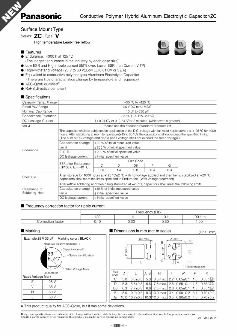
Features Endurance: 4000 h at 125 °C
(The longest endurance in the industry by each case size)
Low ESR and High ripple current (85% over, Lower ESR than Current V-TP)
High-withstand voltage (25 V to 63 V),Low LC(0.01 CV or 3 μA)
Equivalent to conductive polymer type Aluminum Electrolytic Capacitor
(There are little characteristics change by temperature and frequency)
AEC-Q200 qualifi ed
RoHS directive compliant
Surface Mount Type
Series: ZC Type: V High temperature Lead-Free refl ow
Specifi cations
Category Temp. Range –55 °C to +125 °C
Rated W.V.Range 25 V.DC to 63 V.DC
Nominal Cap.Range 10 μF to 330 μF
Capacitance Tolerance ±20 % (120 Hz/+20 °C)
DC Leakage Cur rent I < 0.01 CV or 3 (μA) After 2 minutes (whichever is greater)
tan d Please see the attached Standard Products list
Endurance
The capacitor shall be subjected to application of the D.C. voltage with full rated ripple current at +125 °C for 4000 hours. After stabilizing at room temperature(+15 to 35 °C), the capacitor shall not exceed the specifi ed limits.(The sum of DC voltage and ripple peak voltage shall not exceed the rated voltage.)
Capacitance change ±30 % of initial measured value
tan d < 200 % of initial specifi ed value
E. S. R. < 200 % of initial specifi ed value
DC leakage current < initial specifi ed value
ESR after Endurance(Ω/100 kHz) (–40 °C)
Size Code
C D D8 F G
2.0 1.4 0.8 0.4 0.3
Shelf LifeAfter storage for 1000 hours at +125 °C±2 °C with no voltage applied and then being stabilized at +20 °C, capacitors shall meet the limits specifi ed in Endurance. (With voltage treatment)
Resistance toSoldering Heat
After refl ow soldering and then being stabilized at +20 °C, capacitors shall meet the following limits.
Capacitance change ±10 % of initial measured value
tan d < initial specifi ed value
DC leakage current < initial specifi ed value
Di men sions in mm (not to scale) Marking
Example:25 V 33 μF Marking color : BLACK
Frequency (Hz)
120 1 k 10 k 100 k to
Correction factor 0.10 0.30 0.60 1.00
Frequency correction factor for ripple current
Sizecode
D L A, B H I W P K
C 5.0 5.8±0.3 5.3 6.5 max. 2.2 0.65±0.1 1.5 0.35 - 0.20
D 6.3 5.8±0.3 6.6 7.8 max. 2.6 0.65±0.1 1.8 0.35 - 0.20
D8 6.3 7.7±0.3 6.6 7.8 max. 2.6 0.65±0.1 1.8 0.35 - 0.20
F 8.0 10.2±0.3 8.3 10.0 max. 3.4 0.90±0.2 3.1 0.70±0.2
G 10.0 10.2±0.3 10.3 12.0 max. 3.5 0.90±0.2 4.6 0.70±0.2
+ 0.15
+ 0.15
+ 0.15
Rated Voltage Mark
E 25 V
V 35 V
H 50 V
J 63 V
(Unit : mm)
This product qualify for AEC-Q200, but it has some deviations.
01 Mar. 2014
Design and specifi cations are each subject to change without notice. Ask factory for the current technical specifi cations before purchase and/or use.Should a safety concern arise regarding this product, please be sure to contact us immediately.
Conductive Polymer Hybrid Aluminum Electrolytic Capacitor/ZC
– EEE-5 –
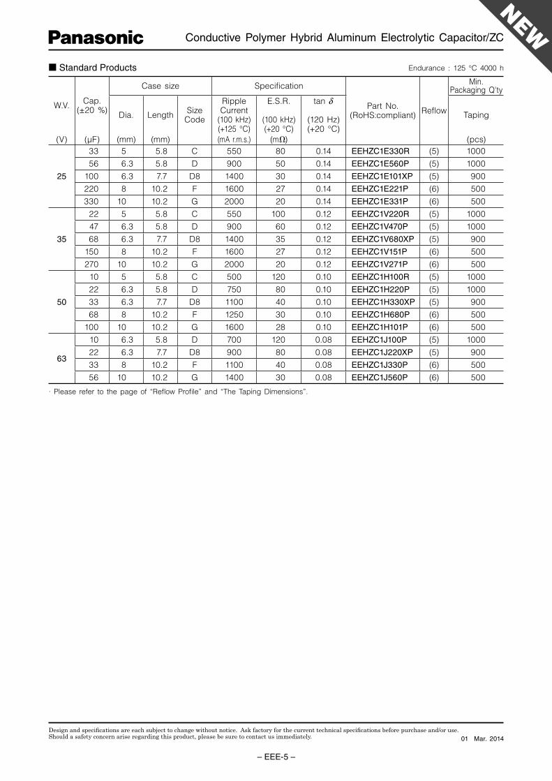
Standard Products
· Please refer to the page of “Refl ow Profi le” and “The Taping Dimensions”.
Endurance : 125 °C 4000 h
W.V.Cap.
(±20 %)
Case size Specifi cation
Part No.(RoHS:compliant)
Refl ow
Min.Packaging Q'ty
Dia. LengthSize
Code
RippleCurrent
(100 kHz)(+125 °C)
E.S.R.
(100 kHz)(+20 °C)
tan d
(120 Hz)(+20 °C)
Taping
(V) (μF) (mm) (mm) (mA r.m.s.) (mΩ) (pcs)
25
33 5 5.8 C 550 80 0.14 EEHZC1E330R (5) 1000
56 6.3 5.8 D 900 50 0.14 EEHZC1E560P (5) 1000
100 6.3 7.7 D8 1400 30 0.14 EEHZC1E101XP (5) 900
220 8 10.2 F 1600 27 0.14 EEHZC1E221P (6) 500
330 10 10.2 G 2000 20 0.14 EEHZC1E331P (6) 500
35
22 5 5.8 C 550 100 0.12 EEHZC1V220R (5) 1000
47 6.3 5.8 D 900 60 0.12 EEHZC1V470P (5) 1000
68 6.3 7.7 D8 1400 35 0.12 EEHZC1V680XP (5) 900
150 8 10.2 F 1600 27 0.12 EEHZC1V151P (6) 500
270 10 10.2 G 2000 20 0.12 EEHZC1V271P (6) 500
50
10 5 5.8 C 500 120 0.10 EEHZC1H100R (5) 1000
22 6.3 5.8 D 750 80 0.10 EEHZC1H220P (5) 1000
33 6.3 7.7 D8 1100 40 0.10 EEHZC1H330XP (5) 900
68 8 10.2 F 1250 30 0.10 EEHZC1H680P (6) 500
100 10 10.2 G 1600 28 0.10 EEHZC1H101P (6) 500
63
10 6.3 5.8 D 700 120 0.08 EEHZC1J100P (5) 1000
22 6.3 7.7 D8 900 80 0.08 EEHZC1J220XP (5) 900
33 8 10.2 F 1100 40 0.08 EEHZC1J330P (6) 500
56 10 10.2 G 1400 30 0.08 EEHZC1J560P (6) 500
01 Mar. 2014
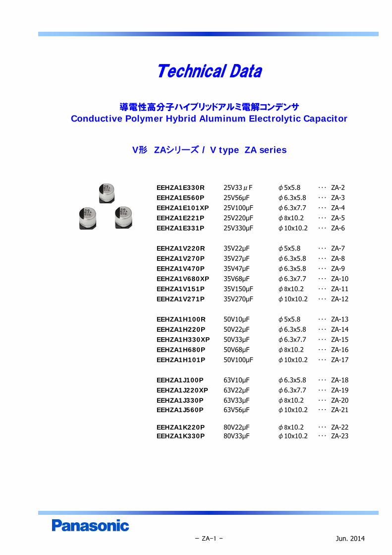
Technical Data
導電性高分子ハイブリッドアルミ電解コンデンサConductive Polymer Hybrid Aluminum Electrolytic Capacitor
V形 ZAシリーズ / V type ZA series
EEHZA1E330R 25V33μF φ5x5.8 ・・・ ZA-2EEHZA1E560P 25V56μF φ6.3x5.8 ・・・ ZA-3EEHZA1E101XP 25V100μF φ6.3x7.7 ・・・ ZA-4EEHZA1E221P 25V220μF φ8x10.2 ・・・ ZA-5EEHZA1E331P 25V330μF φ10x10.2 ・・・ ZA-6
EEHZA1V220R 35V22μF φ5x5.8 ・・・ ZA-7EEHZA1V270P 35V27μF φ6.3x5.8 ・・・ ZA-8EEHZA1V470P 35V47μF φ6.3x5.8 ・・・ ZA-9EEHZA1V680XP 35V68μF φ6.3x7.7 ・・・ ZA-10EEHZA1V151P 35V150μF φ8x10.2 ・・・ ZA-11EEHZA1V271P 35V270μF φ10x10.2 ・・・ ZA-12
EEHZA1H100R 50V10μF φ5x5.8 ・・・ ZA-13EEHZA1H220P 50V22μF φ6.3x5.8 ・・・ ZA-14EEHZA1H330XP 50V33μF φ6.3x7.7 ・・・ ZA-15EEHZA1H680P 50V68μF φ8x10.2 ・・・ ZA-16EEHZA1H101P 50V100μF φ10x10.2 ・・・ ZA-17
EEHZA1J100P 63V10μF φ6.3x5.8 ・・・ ZA-18EEHZA1J220XP 63V22μF φ6.3x7.7 ・・・ ZA-19EEHZA1J330P 63V33μF φ8x10.2 ・・・ ZA-20EEHZA1J560P 63V56μF φ10x10.2 ・・・ ZA-21
EEHZA1K220P 80V22μF φ8x10.2 ・・・ ZA-22EEHZA1K330P 80V33μF φ10x10.2 ・・・ ZA-23
Jun. 2014- ZA-1 -
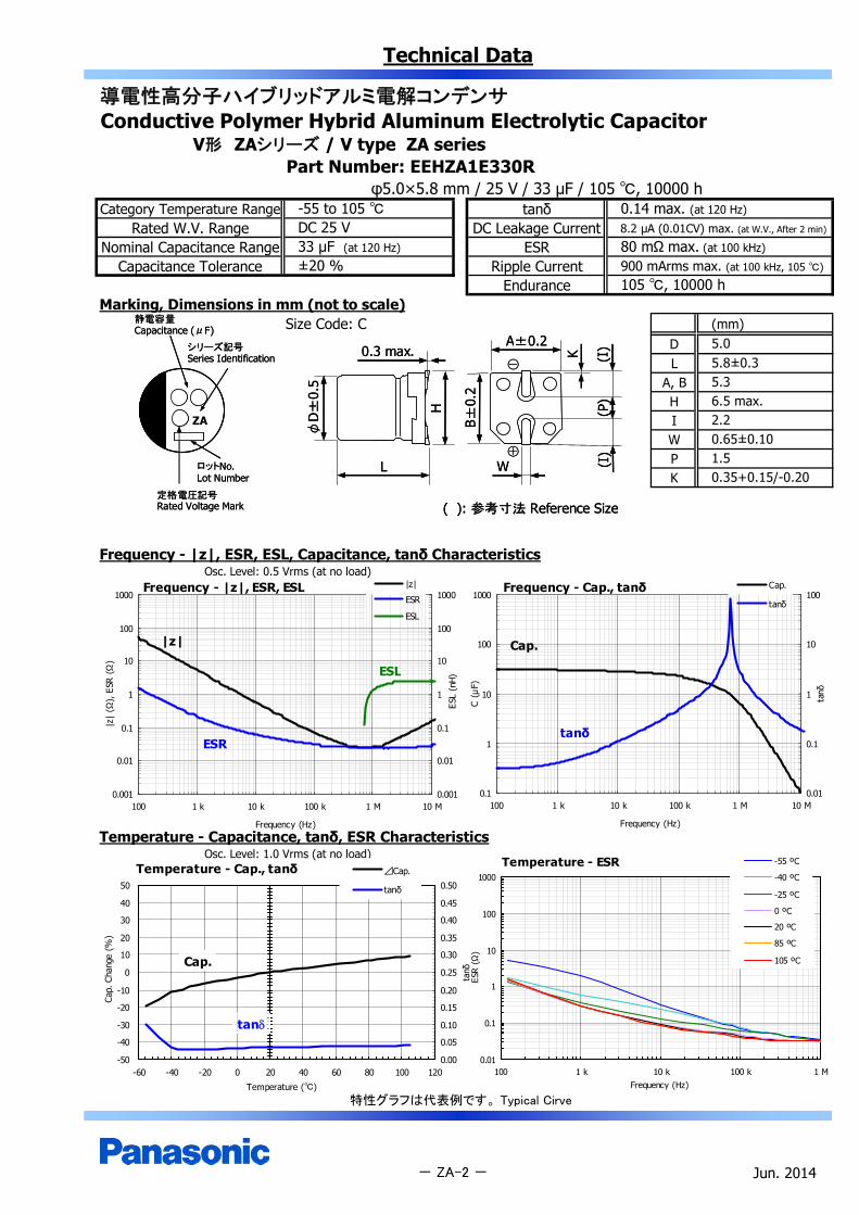
Technical Data
導電性高分子ハイブリッドアルミ電解コンデンサConductive Polymer Hybrid Aluminum Electrolytic Capacitor
V形 ZAシリーズ / V type ZA seriesPart Number: EEHZA1E330R
φ5.0×5.8 mm / 25 V / 33 μF / 105 , 10000 hCategory Temperature Range tanδ
Rated W.V. Range DC Leakage CurrentNominal Capacitance Range ESR
Capacitance Tolerance Ripple CurrentEndurance
Marking, Dimensions in mm (not to scale)Size Code: C (mm)
DL
A, BH
ZA IWPK
Frequency - |z|, ESR, ESL, Capacitance, tanδ CharacteristicsOsc. Level: 0.5 Vrms (at no load)
Temperature - Capacitance, tanδ, ESR CharacteristicsOsc. Level: 1.0 Vrms (at no load)
特性グラフは代表例です。 Typical Cirve
Jun. 2014
5.05.8±0.35.36.5 max.
- ZA-2 -
2.20.65±0.101.50.35+0.15/-0.20
105 , 10000 h±20 %
-55 to 105 DC 25 V33 μF (at 120 Hz)
0.14 max. (at 120 Hz)
8.2 µA (0.01CV) max. (at W.V., After 2 min)
80 mΩ max. (at 100 kHz)
900 mArms max. (at 100 kHz, 105 )
Frequency - |z|, ESR, ESL
0.001
0.01
0.1
1
10
100
1000
100 1 k 10 k 100 k 1 M 10 M
Frequency (Hz)
|z|
(Ω),
ESR
(Ω)
0.001
0.01
0.1
1
10
100
1000
ESL
(nH)
|z|
ESR
ESL
|z|
ESR
ESL
Frequency - Cap., tanδ
0.1
1
10
100
1000
100 1 k 10 k 100 k 1 M 10 M
Frequency (Hz)
C (μ
F)
0.01
0.1
1
10
100
tanδ
Cap.
tanδ
Cap.
tanδ
Temperature - Cap., tanδ
-50
-40
-30
-20
-10
0
10
20
30
40
50
-60 -40 -20 0 20 40 60 80 100 120
Temperature ()
Cap.
Cha
nge
(%)
0.00
0.05
0.10
0.15
0.20
0.25
0.30
0.35
0.40
0.45
0.50
tanδ
⊿Cap.
tanδ
Cap.
tan
Temperature - ESR
0.01
0.1
1
10
100
1000
100 1 k 10 k 100 k 1 MFrequency (Hz)
ESR
(Ω
)
-55 ºC
-40 ºC
-25 ºC
0 ºC
20 ºC
85 ºC
105 ºC
静電容量Capacitance (μF)
シリーズ記号Series Identification
定格電圧記号Rated Voltage Mark
ロットNo.Lot Number
静電容量Capacitance (μF)
シリーズ記号Series Identification
定格電圧記号Rated Voltage Mark
ロットNo.Lot Number
K
A±0.2
( ): 参考寸法 Reference Size
(I)
B±0.
2
0.3 max.
H
L
φD
±0.
5
W
(P)
(I)
⊕
⊖
K
A±0.2
( ): 参考寸法 Reference Size
(I)
B±0.
2
0.3 max.
H
L
φD
±0.
5
W
(P)
(I)
⊕
⊖

Technical Data
導電性高分子ハイブリッドアルミ電解コンデンサConductive Polymer Hybrid Aluminum Electrolytic Capacitor
V形 ZAシリーズ / V type ZA seriesPart Number: EEHZA1E560P
φ6.3×5.8 mm / 25 V / 56 μF / 105 , 10000 hCategory Temperature Range tanδ
Rated W.V. Range DC Leakage CurrentNominal Capacitance Range ESR
Capacitance Tolerance Ripple CurrentEndurance
Marking, Dimensions in mm (not to scale)Size Code: D (mm)
DL
A, BH
ZA IWPK
Frequency - |z|, ESR, ESL, Capacitance, tanδ CharacteristicsOsc. Level: 0.5 Vrms (at no load)
Temperature - Capacitance, tanδ, ESR CharacteristicsOsc. Level: 1.0 Vrms (at no load)
特性グラフは代表例です。 Typical Cirve
Jun. 2014- ZA-3 -
105 , 10000 h±20 %
-55 to 105 DC 25 V56 μF (at 120 Hz)
0.14 max. (at 120 Hz)
14 µA (0.01CV) max. (at W.V., After 2 min)
50 mΩ max. (at 100 kHz)
1300 mArms max. (at 100 kHz, 105 )
2.60.65±0.101.80.35+0.15/-0.20
6.35.8±0.36.67.8 max.
Temperature - ESR
0.01
0.1
1
10
100
1000
100 1 k 10 k 100 k 1 MFrequency (Hz)
ESR
(Ω)
-55 ºC
-40 ºC
-25 ºC
0 ºC
20 ºC
85 ºC
105 ºC
Frequency - Cap., tanδ
0.1
1
10
100
1000
100 1 k 10 k 100 k 1 M 10 M
Frequency (Hz)
C (μ
F)
0.01
0.1
1
10
100
tanδ
Cap.
tanδ
Cap.
tanδ
Frequency - |z|, ESR, ESL
0.001
0.01
0.1
1
10
100
1000
100 1 k 10 k 100 k 1 M 10 M
Frequency (Hz)
|z|
(Ω),
ESR
(Ω
)
0.001
0.01
0.1
1
10
100
1000
ESL
(nH
)
|z|
ESR
ESL
|z|
ESR
ESL
Temperature - Cap., tanδ
-50
-40
-30
-20
-10
0
10
20
30
40
50
-60 -40 -20 0 20 40 60 80 100 120
Temperature ()
Cap.
Cha
nge
(%)
0.00
0.05
0.10
0.15
0.20
0.25
0.30
0.35
0.40
0.45
0.50
tanδ
⊿Cap.
tanδ
Cap.
tan
静電容量Capacitance (μF)
シリーズ記号Series Identification
定格電圧記号Rated Voltage Mark
ロットNo.Lot Number
静電容量Capacitance (μF)
シリーズ記号Series Identification
定格電圧記号Rated Voltage Mark
ロットNo.Lot Number
K
A±0.2
( ): 参考寸法 Reference Size
(I)
B±0.
2
0.3 max.
H
L
φD
±0.
5
W
(P)
(I)
⊕
⊖
K
A±0.2
( ): 参考寸法 Reference Size
(I)
B±0.
2
0.3 max.
H
L
φD
±0.
5
W
(P)
(I)
⊕
⊖

Technical Data
導電性高分子ハイブリッドアルミ電解コンデンサConductive Polymer Hybrid Aluminum Electrolytic Capacitor
V形 ZAシリーズ / V type ZA seriesPart Number: EEHZA1E101XP
φ6.3×7.7 mm / 25 V / 100 μF / 105 , 10000 hCategory Temperature Range tanδ
Rated W.V. Range DC Leakage CurrentNominal Capacitance Range ESR
Capacitance Tolerance Ripple CurrentEndurance
Marking, Dimensions in mm (not to scale)Size Code: D8 (mm)
DL
A, BH
ZA IWPK
Frequency - |z|, ESR, ESL, Capacitance, tanδ CharacteristicsOsc. Level: 0.5 Vrms (at no load)
Temperature - Capacitance, tanδ, ESR CharacteristicsOsc. Level: 1.0 Vrms (at no load)
特性グラフは代表例です。 Typical Cirve
Jun. 2014- ZA-4 -
105 , 10000 h±20 %
-55 to 105 DC 25 V100 μF (at 120 Hz)
0.14 max. (at 120 Hz)
25.0 µA (0.01CV) max. (at W.V., After 2 min)
30 mΩ max. (at 100 kHz)
2000 mArms max. (at 100 kHz, 105 )
2.60.65±0.101.80.35+0.15/-0.20
6.37.7±0.36.67.8 max.
Frequency - |z|, ESR, ESL
0.001
0.01
0.1
1
10
100
1000
100 1 k 10 k 100 k 1 M 10 M
Frequency (Hz)
|z|
(Ω),
ESR
(Ω
)
0.001
0.01
0.1
1
10
100
1000
ESL
(nH
)
|z|
ESR
ESL
|z|
ESR
ESL
Frequency - Cap., tanδ
0.1
1
10
100
1000
100 1 k 10 k 100 k 1 M 10 M
Frequency (Hz)
C (μ
F)
0.01
0.1
1
10
100
tanδ
Cap.
tanδ
Cap.
tanδ
Temperature - Cap., tanδ
-50
-40
-30
-20
-10
0
10
20
30
40
50
-60 -40 -20 0 20 40 60 80 100 120
Temperature ()
Cap.
Cha
nge
(%)
0.00
0.05
0.10
0.15
0.20
0.25
0.30
0.35
0.40
0.45
0.50
tanδ
⊿Cap.
tanδ
Cap.
tan
Temperature - ESR
0.01
0.1
1
10
100
1000
100 1 k 10 k 100 k 1 MFrequency (Hz)
ESR
(Ω)
-55 ºC
-40 ºC
-25 ºC
0 ºC
20 ºC
85 ºC
105 ºC
静電容量Capacitance (μF)
シリーズ記号Series Identification
定格電圧記号Rated Voltage Mark
ロットNo.Lot Number
静電容量Capacitance (μF)
シリーズ記号Series Identification
定格電圧記号Rated Voltage Mark
ロットNo.Lot Number
K
A±0.2
( ): 参考寸法 Reference Size
(I)
B±0.
2
0.3 max.
H
L
φD
±0.
5
W
(P)
(I)
⊕
⊖
K
A±0.2
( ): 参考寸法 Reference Size
(I)
B±0.
2
0.3 max.
H
L
φD
±0.
5
W
(P)
(I)
⊕
⊖
Technical Data
導電性高分子ハイブリッドアルミ電解コンデンサConductive Polymer Hybrid Aluminum Electrolytic Capacitor
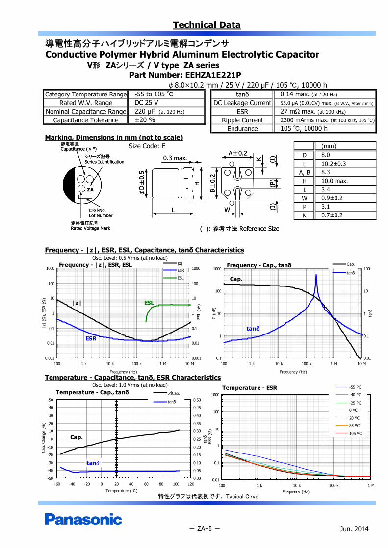
V形 ZAシリーズ / V type ZA seriesPart Number: EEHZA1E221P
φ8.0×10.2 mm / 25 V / 220 μF / 105 , 10000 hCategory Temperature Range tanδ
Rated W.V. Range DC Leakage CurrentNominal Capacitance Range ESR
Capacitance Tolerance Ripple CurrentEndurance
Marking, Dimensions in mm (not to scale)Size Code: F (mm)
DL
A, BH
ZA IWPK
Frequency - |z|, ESR, ESL, Capacitance, tanδ CharacteristicsOsc. Level: 0.5 Vrms (at no load)
Temperature - Capacitance, tanδ, ESR CharacteristicsOsc. Level: 1.0 Vrms (at no load)
特性グラフは代表例です。 Typical Cirve
Jun. 2014- ZA-5 -
105 , 10000 h
0.14 max. (at 120 Hz)
55.0 µA (0.01CV) max. (at W.V., After 2 min)
27 mΩ max. (at 100 kHz)
2300 mArms max. (at 100 kHz, 105 )±20 %
-55 to 105 DC 25 V220 μF (at 120 Hz)
3.40.9±0.23.10.7±0.2
8.010.2±0.38.310.0 max.
Frequency - |z|, ESR, ESL
0.001
0.01
0.1
1
10
100
1000
100 1 k 10 k 100 k 1 M 10 M
Frequency (Hz)
|z|
(Ω),
ESR
(Ω)
0.001
0.01
0.1
1
10
100
1000
ESL
(nH)
|z|
ESR
ESL
|z|
ESR
ESL
Frequency - Cap., tanδ
0.1
1
10
100
1000
100 1 k 10 k 100 k 1 M 10 M
Frequency (Hz)
C (μ
F)
0.01
0.1
1
10
100
tanδ
Cap.
tanδ
Cap.
tanδ
Temperature - Cap., tanδ
-50
-40
-30
-20
-10
0
10
20
30
40
50
-60 -40 -20 0 20 40 60 80 100 120
Temperature ()
Cap.
Cha
nge
(%)
0.00
0.05
0.10
0.15
0.20
0.25
0.30
0.35
0.40
0.45
0.50
tanδ
⊿Cap.
tanδ
Cap.
tan
Temperature - ESR
0.01
0.1
1
10
100
1000
100 1 k 10 k 100 k 1 MFrequency (Hz)
ESR
(Ω)
-55 ºC
-40 ºC
-25 ºC
0 ºC
20 ºC
85 ºC
105 ºC
静電容量Capacitance (μF)
シリーズ記号Series Identification
定格電圧記号Rated Voltage Mark
ロットNo.Lot Number
静電容量Capacitance (μF)
シリーズ記号Series Identification
定格電圧記号Rated Voltage Mark
ロットNo.Lot Number
K
A±0.2
( ): 参考寸法 Reference Size
(I)
B±0.
2
0.3 max.
H
L
φD
±0.
5
W
(P)
(I)
⊕
⊖
K
A±0.2
( ): 参考寸法 Reference Size
(I)
B±0.
2
0.3 max.
H
L
φD
±0.
5
W
(P)
(I)
⊕
⊖
Technical Data
導電性高分子ハイブリッドアルミ電解コンデンサConductive Polymer Hybrid Aluminum Electrolytic Capacitor
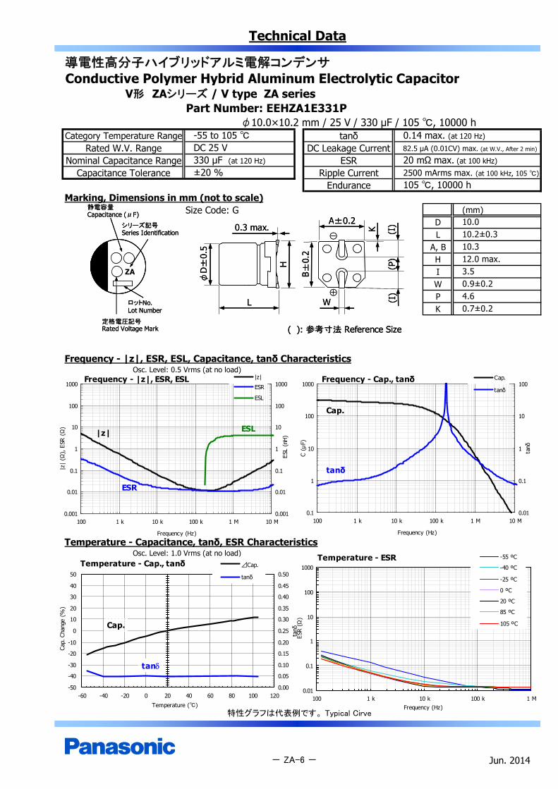
V形 ZAシリーズ / V type ZA seriesPart Number: EEHZA1E331P
φ10.0×10.2 mm / 25 V / 330 μF / 105 , 10000 hCategory Temperature Range tanδ
Rated W.V. Range DC Leakage CurrentNominal Capacitance Range ESR
Capacitance Tolerance Ripple CurrentEndurance
Marking, Dimensions in mm (not to scale)Size Code: G (mm)
DL
A, BH
ZA IWPK
Frequency - |z|, ESR, ESL, Capacitance, tanδ CharacteristicsOsc. Level: 0.5 Vrms (at no load)
Temperature - Capacitance, tanδ, ESR CharacteristicsOsc. Level: 1.0 Vrms (at no load)
特性グラフは代表例です。 Typical Cirve
Jun. 2014
10.010.2±0.310.312.0 max.
- ZA-6 -
3.50.9±0.24.60.7±0.2
105 , 10000 h±20 %
-55 to 105 DC 25 V330 μF (at 120 Hz)
0.14 max. (at 120 Hz)
82.5 µA (0.01CV) max. (at W.V., After 2 min)
20 mΩ max. (at 100 kHz)
2500 mArms max. (at 100 kHz, 105 )
Temperature - ESR
0.01
0.1
1
10
100
1000
100 1 k 10 k 100 k 1 MFrequency (Hz)
ESR
(Ω)
-55 ºC
-40 ºC
-25 ºC
0 ºC
20 ºC
85 ºC
105 ºC
Frequency - Cap., tanδ
0.1
1
10
100
1000
100 1 k 10 k 100 k 1 M 10 M
Frequency (Hz)
C (μ
F)
0.01
0.1
1
10
100
tanδ
Cap.
tanδ
Cap.
tanδ
Frequency - |z|, ESR, ESL
0.001
0.01
0.1
1
10
100
1000
100 1 k 10 k 100 k 1 M 10 M
Frequency (Hz)
|z|
(Ω),
ESR
(Ω
)
0.001
0.01
0.1
1
10
100
1000
ESL
(nH
)
|z|
ESR
ESL
|z|
ESR
ESL
Temperature - Cap., tanδ
-50
-40
-30
-20
-10
0
10
20
30
40
50
-60 -40 -20 0 20 40 60 80 100 120
Temperature ()
Cap.
Cha
nge
(%)
0.00
0.05
0.10
0.15
0.20
0.25
0.30
0.35
0.40
0.45
0.50
tanδ
⊿Cap.
tanδ
Cap.
tan
静電容量Capacitance (μF)
シリーズ記号Series Identification
定格電圧記号Rated Voltage Mark
ロットNo.Lot Number
静電容量Capacitance (μF)
シリーズ記号Series Identification
定格電圧記号Rated Voltage Mark
ロットNo.Lot Number
K
A±0.2
( ): 参考寸法 Reference Size
(I)
B±0.
2
0.3 max.
H
L
φD
±0.
5
W
(P)
(I)
⊕
⊖
K
A±0.2
( ): 参考寸法 Reference Size
(I)
B±0.
2
0.3 max.
H
L
φD
±0.
5
W
(P)
(I)
⊕
⊖
Technical Data
導電性高分子ハイブリッドアルミ電解コンデンサConductive Polymer Hybrid Aluminum Electrolytic Capacitor
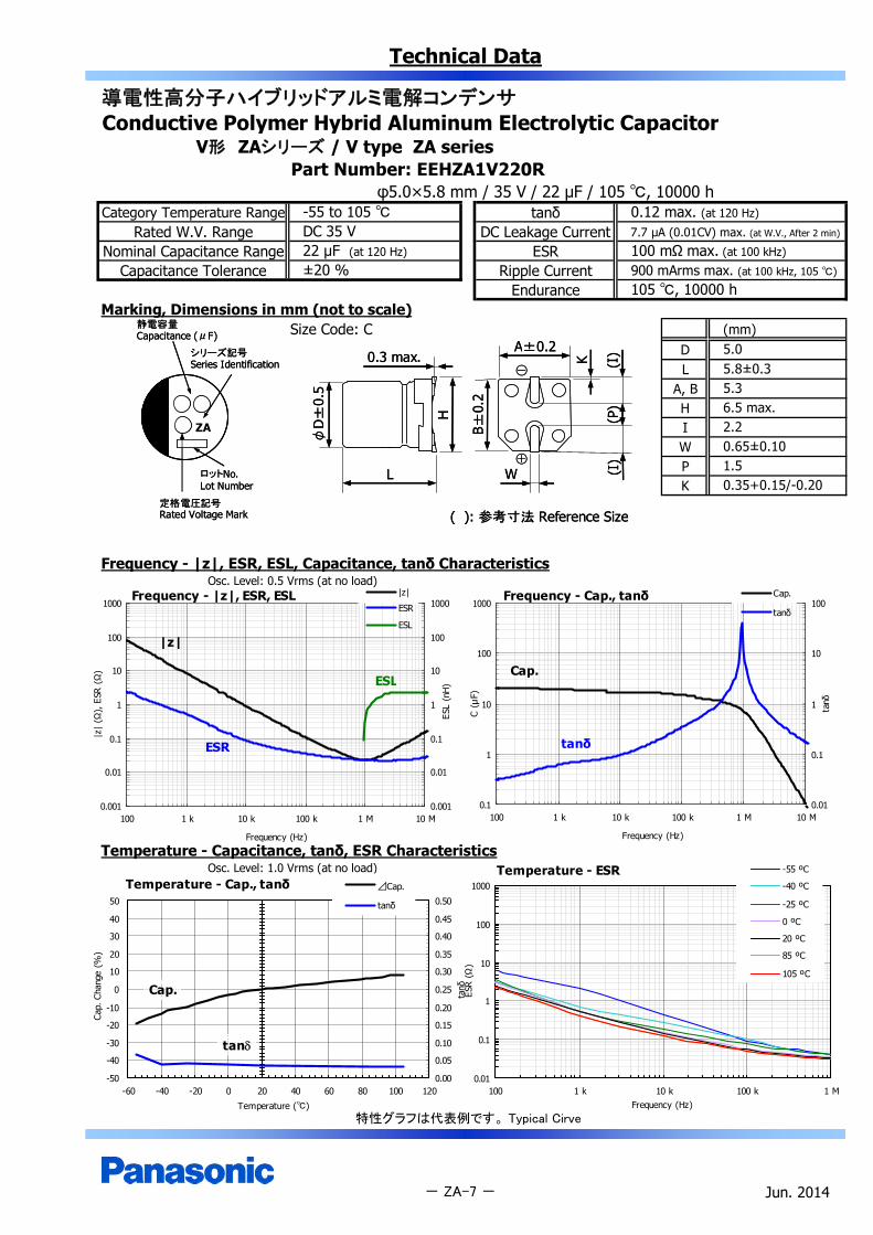
V形 ZAシリーズ / V type ZA seriesPart Number: EEHZA1V220R
φ5.0×5.8 mm / 35 V / 22 μF / 105 , 10000 hCategory Temperature Range tanδ
Rated W.V. Range DC Leakage CurrentNominal Capacitance Range ESR
Capacitance Tolerance Ripple CurrentEndurance
Marking, Dimensions in mm (not to scale)Size Code: C (mm)
DL
A, BH
ZA IWPK
Frequency - |z|, ESR, ESL, Capacitance, tanδ CharacteristicsOsc. Level: 0.5 Vrms (at no load)
Temperature - Capacitance, tanδ, ESR CharacteristicsOsc. Level: 1.0 Vrms (at no load)
特性グラフは代表例です。 Typical Cirve
Jun. 2014
5.05.8±0.35.36.5 max.
- ZA-7 -
2.20.65±0.101.50.35+0.15/-0.20
105 , 10000 h±20 %
-55 to 105 DC 35 V22 μF (at 120 Hz)
0.12 max. (at 120 Hz)
7.7 µA (0.01CV) max. (at W.V., After 2 min)
100 mΩ max. (at 100 kHz)
900 mArms max. (at 100 kHz, 105 )
Temperature - ESR
0.01
0.1
1
10
100
1000
100 1 k 10 k 100 k 1 MFrequency (Hz)
ESR
(Ω)
-55 ºC
-40 ºC
-25 ºC
0 ºC
20 ºC
85 ºC
105 ºC
Frequency - Cap., tanδ
0.1
1
10
100
1000
100 1 k 10 k 100 k 1 M 10 M
Frequency (Hz)
C (μ
F)
0.01
0.1
1
10
100
tanδ
Cap.
tanδ
Cap.
tanδ
Frequency - |z|, ESR, ESL
0.001
0.01
0.1
1
10
100
1000
100 1 k 10 k 100 k 1 M 10 M
Frequency (Hz)
|z|
(Ω),
ESR
(Ω
)
0.001
0.01
0.1
1
10
100
1000
ESL
(nH
)
|z|
ESR
ESL
|z|
ESR
ESL
Temperature - Cap., tanδ
-50
-40
-30
-20
-10
0
10
20
30
40
50
-60 -40 -20 0 20 40 60 80 100 120
Temperature ()
Cap.
Cha
nge
(%)
0.00
0.05
0.10
0.15
0.20
0.25
0.30
0.35
0.40
0.45
0.50
tanδ
⊿Cap.
tanδ
Cap.
tan
静電容量Capacitance (μF)
シリーズ記号Series Identification
定格電圧記号Rated Voltage Mark
ロットNo.Lot Number
静電容量Capacitance (μF)
シリーズ記号Series Identification
定格電圧記号Rated Voltage Mark
ロットNo.Lot Number
K
A±0.2
( ): 参考寸法 Reference Size
(I)
B±0.
2
0.3 max.
H
L
φD
±0.
5
W
(P)
(I)
⊕
⊖
K
A±0.2
( ): 参考寸法 Reference Size
(I)
B±0.
2
0.3 max.
H
L
φD
±0.
5
W
(P)
(I)
⊕
⊖

Technical Data
導電性高分子ハイブリッドアルミ電解コンデンサConductive Polymer Hybrid Aluminum Electrolytic Capacitor
V形 ZAシリーズ / V type ZA seriesPart Number: EEHZA1V270P
φ6.3×5.8 mm / 35 V / 27 μF / 105 , 10000 hCategory Temperature Range tanδ
Rated W.V. Range DC Leakage CurrentNominal Capacitance Range ESR
Capacitance Tolerance Ripple CurrentEndurance
Marking, Dimensions in mm (not to scale)Size Code: D (mm)
DL
A, BH
ZA IWPK
Frequency - |z|, ESR, ESL, Capacitance, tanδ CharacteristicsOsc. Level: 0.5 Vrms (at no load)
Temperature - Capacitance, tanδ, ESR CharacteristicsOsc. Level: 1.0 Vrms (at no load)
特性グラフは代表例です。 Typical Cirve
Jun. 2014
1.80.35+0.15/-0.20
6.35.8±0.36.67.8 max.2.60.65±0.10
- ZA-8 -
105 , 10000 h
0.12 max. (at 120 Hz)
9.4 µA (0.01CV) max. (at W.V., After 2 min)
60 mΩ max. (at 100 kHz)
1300 mArms max. (at 100 kHz, 105 )±20 %
-55 to 105 DC 35 V27 μF (at 120 Hz)
Frequency - |z|, ESR, ESL
0.001
0.01
0.1
1
10
100
1000
100 1 k 10 k 100 k 1 M 10 M
Frequency (Hz)
|z|
(Ω),
ESR
(Ω)
0.001
0.01
0.1
1
10
100
1000
ESL
(nH)
|z|
ESR
ESL
|z|
ESR
ESL
Frequency - Cap., tanδ
0.1
1
10
100
1000
100 1 k 10 k 100 k 1 M 10 M
Frequency (Hz)
C (μ
F)
0.01
0.1
1
10
100
tanδ
Cap.
tanδ
Cap.
tanδ
Temperature - Cap., tanδ
-50
-40
-30
-20
-10
0
10
20
30
40
50
-60 -40 -20 0 20 40 60 80 100 120
Temperature ()
Cap.
Cha
nge
(%)
0.00
0.05
0.10
0.15
0.20
0.25
0.30
0.35
0.40
0.45
0.50
tanδ
⊿Cap.
tanδ
Cap.
tan
Temperature - ESR
0.01
0.1
1
10
100
1000
100 1 k 10 k 100 k 1 MFrequency (Hz)
ESR
(Ω)
-55 ºC
-40 ºC
-25 ºC
0 ºC
20 ºC
85 ºC
105 ºC
静電容量Capacitance (μF)
シリーズ記号Series Identification
定格電圧記号Rated Voltage Mark
ロットNo.Lot Number
静電容量Capacitance (μF)
シリーズ記号Series Identification
定格電圧記号Rated Voltage Mark
ロットNo.Lot Number
K
A±0.2
( ): 参考寸法 Reference Size
(I)
B±0.
2
0.3 max.
H
L
φD
±0.
5
W
(P)
(I)
⊕
⊖
K
A±0.2
( ): 参考寸法 Reference Size
(I)
B±0.
2
0.3 max.
H
L
φD
±0.
5
W
(P)
(I)
⊕
⊖
Technical Data
導電性高分子ハイブリッドアルミ電解コンデンサConductive Polymer Hybrid Aluminum Electrolytic Capacitor
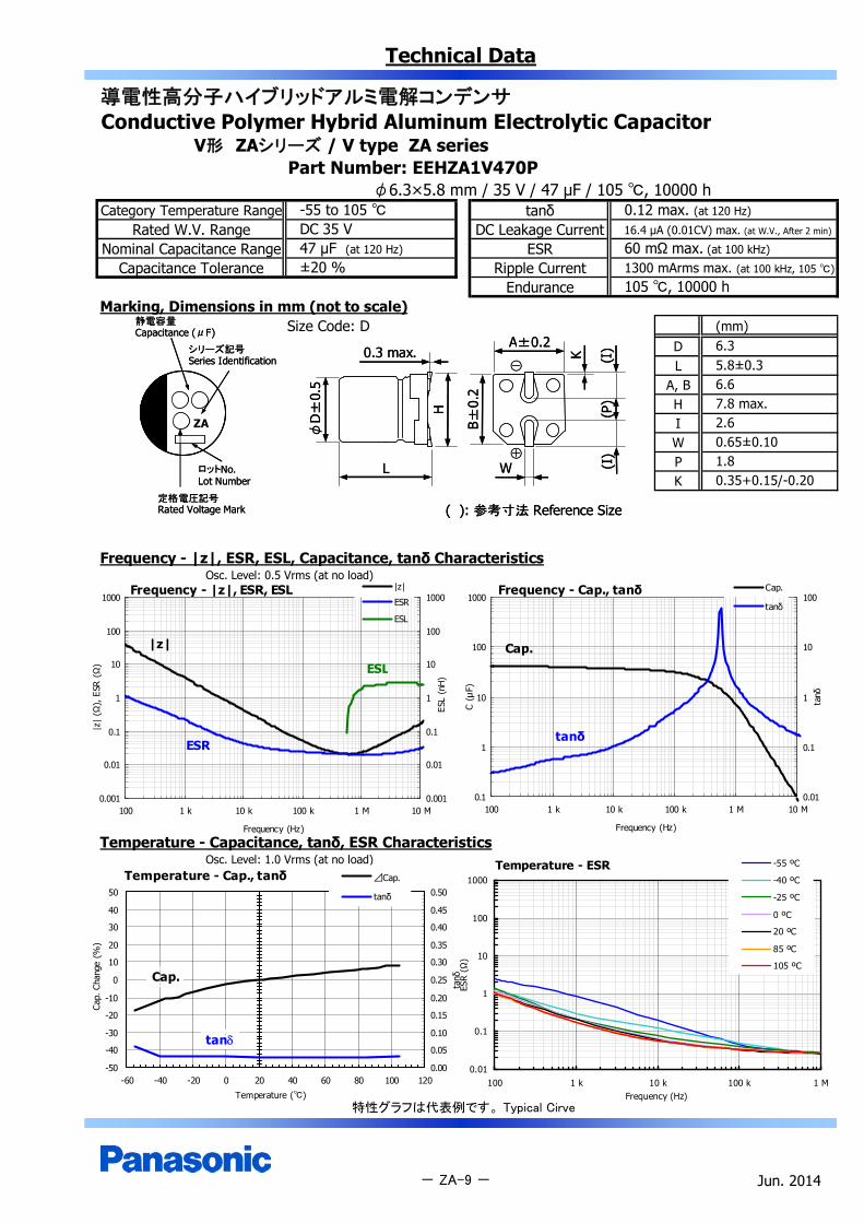
V形 ZAシリーズ / V type ZA seriesPart Number: EEHZA1V470P
φ6.3×5.8 mm / 35 V / 47 μF / 105 , 10000 hCategory Temperature Range tanδ
Rated W.V. Range DC Leakage CurrentNominal Capacitance Range ESR
Capacitance Tolerance Ripple CurrentEndurance
Marking, Dimensions in mm (not to scale)Size Code: D (mm)
DL
A, BH
ZA IWPK
Frequency - |z|, ESR, ESL, Capacitance, tanδ CharacteristicsOsc. Level: 0.5 Vrms (at no load)
Temperature - Capacitance, tanδ, ESR CharacteristicsOsc. Level: 1.0 Vrms (at no load)
特性グラフは代表例です。 Typical Cirve
Jun. 2014- ZA-9 -
105 , 10000 h±20 %
-55 to 105 DC 35 V47 μF (at 120 Hz)
0.12 max. (at 120 Hz)
16.4 µA (0.01CV) max. (at W.V., After 2 min)
60 mΩ max. (at 100 kHz)
1300 mArms max. (at 100 kHz, 105 )
2.60.65±0.101.80.35+0.15/-0.20
6.35.8±0.36.67.8 max.
Temperature - ESR
0.01
0.1
1
10
100
1000
100 1 k 10 k 100 k 1 MFrequency (Hz)
ESR
(Ω)
-55 ºC
-40 ºC
-25 ºC
0 ºC
20 ºC
85 ºC
105 ºC
Frequency - Cap., tanδ
0.1
1
10
100
1000
100 1 k 10 k 100 k 1 M 10 M
Frequency (Hz)
C (μ
F)
0.01
0.1
1
10
100
tanδ
Cap.
tanδ
Cap.
tanδ
Frequency - |z|, ESR, ESL
0.001
0.01
0.1
1
10
100
1000
100 1 k 10 k 100 k 1 M 10 M
Frequency (Hz)
|z|
(Ω),
ESR
(Ω
)
0.001
0.01
0.1
1
10
100
1000
ESL
(nH
)
|z|
ESR
ESL
|z|
ESR
ESL
Temperature - Cap., tanδ
-50
-40
-30
-20
-10
0
10
20
30
40
50
-60 -40 -20 0 20 40 60 80 100 120
Temperature ()
Cap.
Cha
nge
(%)
0.00
0.05
0.10
0.15
0.20
0.25
0.30
0.35
0.40
0.45
0.50
tanδ
⊿Cap.
tanδ
Cap.
tan
静電容量Capacitance (μF)
シリーズ記号Series Identification
定格電圧記号Rated Voltage Mark
ロットNo.Lot Number
静電容量Capacitance (μF)
シリーズ記号Series Identification
定格電圧記号Rated Voltage Mark
ロットNo.Lot Number
K
A±0.2
( ): 参考寸法 Reference Size
(I)
B±0.
2
0.3 max.
H
L
φD
±0.
5
W
(P)
(I)
⊕
⊖
K
A±0.2
( ): 参考寸法 Reference Size
(I)
B±0.
2
0.3 max.
H
L
φD
±0.
5
W
(P)
(I)
⊕
⊖
Technical Data
導電性高分子ハイブリッドアルミ電解コンデンサConductive Polymer Hybrid Aluminum Electrolytic Capacitor
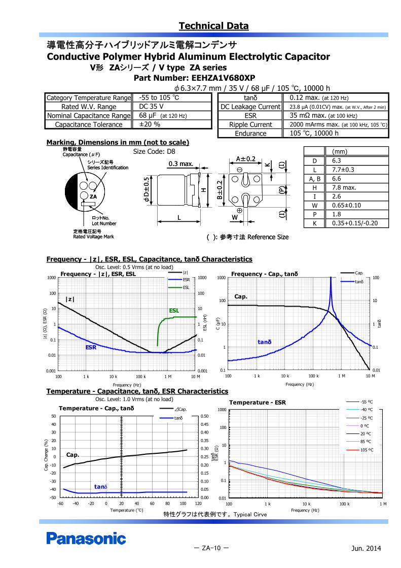
V形 ZAシリーズ / V type ZA seriesPart Number: EEHZA1V680XP
φ6.3×7.7 mm / 35 V / 68 μF / 105 , 10000 hCategory Temperature Range tanδ
Rated W.V. Range DC Leakage CurrentNominal Capacitance Range ESR
Capacitance Tolerance Ripple CurrentEndurance
Marking, Dimensions in mm (not to scale)Size Code: D8 (mm)
DL
A, BH
ZA IWPK
Frequency - |z|, ESR, ESL, Capacitance, tanδ CharacteristicsOsc. Level: 0.5 Vrms (at no load)
Temperature - Capacitance, tanδ, ESR CharacteristicsOsc. Level: 1.0 Vrms (at no load)
特性グラフは代表例です。 Typical Cirve
Jun. 2014- ZA-10 -
105 , 10000 h±20 %
-55 to 105 DC 35 V68 μF (at 120 Hz)
0.12 max. (at 120 Hz)
23.8 µA (0.01CV) max. (at W.V., After 2 min)
35 mΩ max. (at 100 kHz)
2000 mArms max. (at 100 kHz, 105 )
2.60.65±0.101.80.35+0.15/-0.20
6.37.7±0.36.67.8 max.
Temperature - Cap., tanδ
-50
-40
-30
-20
-10
0
10
20
30
40
50
-60 -40 -20 0 20 40 60 80 100 120
Temperature ()
Cap.
Cha
nge
(%)
0.00
0.05
0.10
0.15
0.20
0.25
0.30
0.35
0.40
0.45
0.50
tanδ
⊿Cap.
tanδ
Cap.
tan
Temperature - ESR
0.01
0.1
1
10
100
1000
100 1 k 10 k 100 k 1 MFrequency (Hz)
ESR
(Ω)
-55 ºC
-40 ºC
-25 ºC
0 ºC
20 ºC
85 ºC
105 ºC
Frequency - Cap., tanδ
0.1
1
10
100
1000
100 1 k 10 k 100 k 1 M 10 M
Frequency (Hz)
C (μ
F)
0.01
0.1
1
10
100
tanδ
Cap.
tanδ
Cap.
tanδ
Frequency - |z|, ESR, ESL
0.001
0.01
0.1
1
10
100
1000
100 1 k 10 k 100 k 1 M 10 M
Frequency (Hz)
|z|
(Ω),
ESR
(Ω
)
0.001
0.01
0.1
1
10
100
1000
ESL
(nH
)
|z|
ESR
ESL
|z|
ESR
ESL
静電容量Capacitance (μF)
シリーズ記号Series Identification
定格電圧記号Rated Voltage Mark
ロットNo.Lot Number
静電容量Capacitance (μF)
シリーズ記号Series Identification
定格電圧記号Rated Voltage Mark
ロットNo.Lot Number
K
A±0.2
( ): 参考寸法 Reference Size
(I)
B±0.
2
0.3 max.
H
L
φD
±0.
5
W
(P)
(I)
⊕
⊖
K
A±0.2
( ): 参考寸法 Reference Size
(I)
B±0.
2
0.3 max.
H
L
φD
±0.
5
W
(P)
(I)
⊕
⊖

Technical Data
導電性高分子ハイブリッドアルミ電解コンデンサConductive Polymer Hybrid Aluminum Electrolytic Capacitor
V形 ZAシリーズ / V type ZA seriesPart Number: EEHZA1V151P
φ8.0×10.2 mm / 35 V / 150 μF / 105 , 10000 hCategory Temperature Range tanδ
Rated W.V. Range DC Leakage CurrentNominal Capacitance Range ESR
Capacitance Tolerance Ripple CurrentEndurance
Marking, Dimensions in mm (not to scale)Size Code: F (mm)
DL
A, BH
ZA IWPK
Frequency - |z|, ESR, ESL, Capacitance, tanδ CharacteristicsOsc. Level: 0.5 Vrms (at no load)
Temperature - Capacitance, tanδ, ESR CharacteristicsOsc. Level: 1.0 Vrms (at no load)
特性グラフは代表例です。 Typical Cirve
Jun. 2014- ZA-11 -
105 , 10000 h±20 %
-55 to 105 DC 35 V150 μF (at 120 Hz)
0.12 max. (at 120 Hz)
52.5 µA (0.01CV) max. (at W.V., After 2 min)
27 mΩ max. (at 100 kHz)
2300 mArms max. (at 100 kHz, 105 )
3.40.9±0.23.10.7±0.2
8.010.2±0.38.310.0 max.
Temperature - ESR
0.01
0.1
1
10
100
1000
100 1 k 10 k 100 k 1 MFrequency (Hz)
ESR
(Ω)
-55 ºC
-40 ºC
-25 ºC
0 ºC
20 ºC
85 ºC
105 ºC
Frequency - Cap., tanδ
0.1
1
10
100
1000
100 1 k 10 k 100 k 1 M 10 M
Frequency (Hz)
C (μ
F)
0.01
0.1
1
10
100
tanδ
Cap.
tanδ
Cap.
tanδ
Frequency - |z|, ESR, ESL
0.001
0.01
0.1
1
10
100
1000
100 1 k 10 k 100 k 1 M 10 M
Frequency (Hz)
|z|
(Ω),
ESR
(Ω
)
0.001
0.01
0.1
1
10
100
1000
ESL
(nH
)
|z|
ESR
ESL
|z|
ESR
ESL
Temperature - Cap., tanδ
-50
-40
-30
-20
-10
0
10
20
30
40
50
-60 -40 -20 0 20 40 60 80 100 120
Temperature ()
Cap.
Cha
nge
(%)
0.00
0.05
0.10
0.15
0.20
0.25
0.30
0.35
0.40
0.45
0.50
tanδ
⊿Cap.
tanδ
Cap.
tan
静電容量Capacitance (μF)
シリーズ記号Series Identification
定格電圧記号Rated Voltage Mark
ロットNo.Lot Number
静電容量Capacitance (μF)
シリーズ記号Series Identification
定格電圧記号Rated Voltage Mark
ロットNo.Lot Number
K
A±0.2
( ): 参考寸法 Reference Size
(I)
B±0.
2
0.3 max.
H
L
φD
±0.
5
W
(P)
(I)
⊕
⊖
K
A±0.2
( ): 参考寸法 Reference Size
(I)
B±0.
2
0.3 max.
H
L
φD
±0.
5
W
(P)
(I)
⊕
⊖

Technical Data
導電性高分子ハイブリッドアルミ電解コンデンサConductive Polymer Hybrid Aluminum Electrolytic Capacitor
V形 ZAシリーズ / V type ZA seriesPart Number: EEHZA1V271P
φ10.0×10.2 mm / 35 V / 270 μF / 105 , 10000 hCategory Temperature Range tanδ
Rated W.V. Range DC Leakage CurrentNominal Capacitance Range ESR
Capacitance Tolerance Ripple CurrentEndurance
Marking, Dimensions in mm (not to scale)Size Code: G (mm)
DL
A, BH
ZA IWPK
Frequency - |z|, ESR, ESL, Capacitance, tanδ CharacteristicsOsc. Level: 0.5 Vrms (at no load)
Temperature - Capacitance, tanδ, ESR CharacteristicsOsc. Level: 1.0 Vrms (at no load)
特性グラフは代表例です。 Typical Cirve
Jun. 2014
10.010.2±0.310.312.0 max.
- ZA-12 -
3.50.9±0.24.60.7±0.2
105 , 10000 h±20 %
-55 to 105 DC 35 V270 μF (at 120 Hz)
0.12 max. (at 120 Hz)
94.5 µA (0.01CV) max. (at W.V., After 2 min)
20 mΩ max. (at 100 kHz)
2500 mArms max. (at 100 kHz, 105 )
Temperature - ESR
0.01
0.1
1
10
100
1000
100 1 k 10 k 100 k 1 MFrequency (Hz)
ESR
(Ω)
-55 ºC
-40 ºC
-25 ºC
0 ºC
20 ºC
85 ºC
105 ºC
Frequency - Cap., tanδ
0.1
1
10
100
1000
100 1 k 10 k 100 k 1 M 10 M
Frequency (Hz)
C (μ
F)
0.01
0.1
1
10
100
tanδ
Cap.
tanδ
Cap.
tanδ
Frequency - |z|, ESR, ESL
0.001
0.01
0.1
1
10
100
1000
100 1 k 10 k 100 k 1 M 10 M
Frequency (Hz)
|z|
(Ω),
ESR
(Ω
)
0.001
0.01
0.1
1
10
100
1000
ESL
(nH
)
|z|
ESR
ESL
|z|
ESR
ESL
Temperature - Cap., tanδ
-50
-40
-30
-20
-10
0
10
20
30
40
50
-60 -40 -20 0 20 40 60 80 100 120
Temperature ()
Cap.
Cha
nge
(%)
0.00
0.05
0.10
0.15
0.20
0.25
0.30
0.35
0.40
0.45
0.50
tanδ
⊿Cap.
tanδ
Cap.
tan
静電容量Capacitance (μF)
シリーズ記号Series Identification
定格電圧記号Rated Voltage Mark
ロットNo.Lot Number
静電容量Capacitance (μF)
シリーズ記号Series Identification
定格電圧記号Rated Voltage Mark
ロットNo.Lot Number
K
A±0.2
( ): 参考寸法 Reference Size
(I)
B±0.
2
0.3 max.
H
L
φD
±0.
5
W
(P)
(I)
⊕
⊖
K
A±0.2
( ): 参考寸法 Reference Size
(I)
B±0.
2
0.3 max.
H
L
φD
±0.
5
W
(P)
(I)
⊕
⊖

Technical Data
導電性高分子ハイブリッドアルミ電解コンデンサConductive Polymer Hybrid Aluminum Electrolytic Capacitor
V形 ZAシリーズ / V type ZA seriesPart Number: EEHZA1H100R
φ5.0×5.8 mm / 50 V / 10 μF / 105 , 10000 hCategory Temperature Range tanδ
Rated W.V. Range DC Leakage CurrentNominal Capacitance Range ESR
Capacitance Tolerance Ripple CurrentEndurance
Marking, Dimensions in mm (not to scale)Size Code: C (mm)
DL
A, BH
ZA IWPK
Frequency - |z|, ESR, ESL, Capacitance, tanδ CharacteristicsOsc. Level: 0.5 Vrms (at no load)
Temperature - Capacitance, tanδ, ESR CharacteristicsOsc. Level: 1.0 Vrms (at no load)
特性グラフは代表例です。 Typical Cirve
Jun. 2014- ZA-13 -
105 , 10000 h±20 %
-55 to 105 DC 50 V10 μF (at 120 Hz)
0.1 max. (at 120 Hz)
5 µA (0.01CV) max. (at W.V., After 2 min)
120 mΩ max. (at 100 kHz)
750 mArms max. (at 100 kHz, 105 )
2.20.65±0.101.50.35+0.15/-0.20
5.05.8±0.35.36.5 max.
Frequency - |z|, ESR, ESL
0.001
0.01
0.1
1
10
100
1000
100 1 k 10 k 100 k 1 M 10 M
Frequency (Hz)
|z|
(Ω),
ESR
(Ω)
0.001
0.01
0.1
1
10
100
1000
ESL
(nH)
|z|
ESR
ESL|z|
ESR
ESL
Frequency - Cap., tanδ
0.1
1
10
100
1000
100 1 k 10 k 100 k 1 M 10 M
Frequency (Hz)
C (μ
F)
0.01
0.1
1
10
100
tanδ
Cap.
tanδ
Cap.
tanδ
Temperature - Cap., tanδ
-50
-40
-30
-20
-10
0
10
20
30
40
50
-60 -40 -20 0 20 40 60 80 100 120
Temperature ()
Cap.
Cha
nge
(%)
0.00
0.05
0.10
0.15
0.20
0.25
0.30
0.35
0.40
0.45
0.50
tanδ
⊿Cap.
tanδ
Cap.
tan
Temperature - ESR
0.01
0.1
1
10
100
1000
100 1 k 10 k 100 k 1 MFrequency (Hz)
ESR
(Ω)
-55 ºC
-40 ºC
-25 ºC
0 ºC
20 ºC
85 ºC
105 ºC
静電容量Capacitance (μF)
シリーズ記号Series Identification
定格電圧記号Rated Voltage Mark
ロットNo.Lot Number
静電容量Capacitance (μF)
シリーズ記号Series Identification
定格電圧記号Rated Voltage Mark
ロットNo.Lot Number
K
A±0.2
( ): 参考寸法 Reference Size
(I)
B±0.
2
0.3 max.
H
L
φD
±0.
5
W
(P)
(I)
⊕
⊖
K
A±0.2
( ): 参考寸法 Reference Size
(I)
B±0.
2
0.3 max.
H
L
φD
±0.
5
W
(P)
(I)
⊕
⊖
Technical Data
導電性高分子ハイブリッドアルミ電解コンデンサConductive Polymer Hybrid Aluminum Electrolytic Capacitor
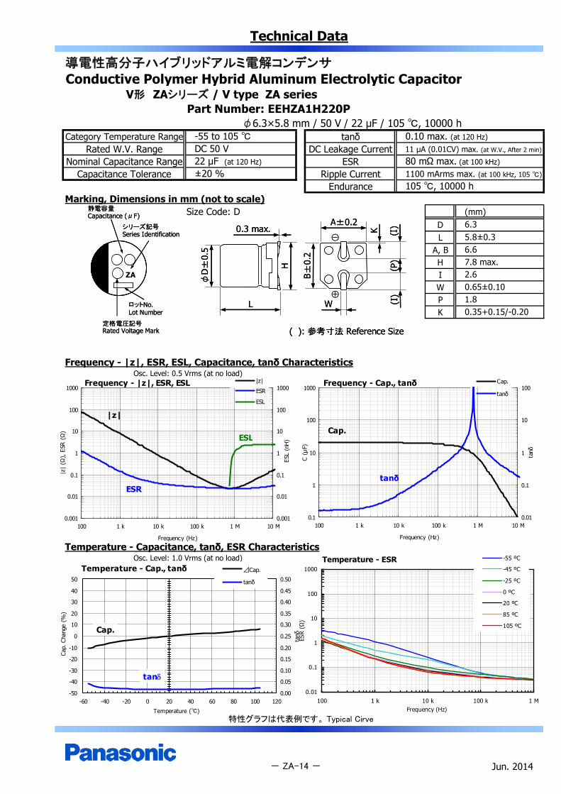
V形 ZAシリーズ / V type ZA seriesPart Number: EEHZA1H220P
φ6.3×5.8 mm / 50 V / 22 μF / 105 , 10000 hCategory Temperature Range tanδ
Rated W.V. Range DC Leakage CurrentNominal Capacitance Range ESR
Capacitance Tolerance Ripple CurrentEndurance
Marking, Dimensions in mm (not to scale)Size Code: D (mm)
DL
A, BH
ZA IWPK
Frequency - |z|, ESR, ESL, Capacitance, tanδ CharacteristicsOsc. Level: 0.5 Vrms (at no load)
Temperature - Capacitance, tanδ, ESR CharacteristicsOsc. Level: 1.0 Vrms (at no load)
特性グラフは代表例です。 Typical Cirve
Jun. 2014- ZA-14 -
105 , 10000 h±20 %
-55 to 105 DC 50 V22 μF (at 120 Hz)
0.10 max. (at 120 Hz)
11 µA (0.01CV) max. (at W.V., After 2 min)
80 mΩ max. (at 100 kHz)
1100 mArms max. (at 100 kHz, 105 )
2.60.65±0.101.80.35+0.15/-0.20
6.35.8±0.36.67.8 max.
Temperature - ESR
0.01
0.1
1
10
100
1000
100 1 k 10 k 100 k 1 MFrequency (Hz)
ESR
(Ω)
-55 ºC
-45 ºC
-25 ºC
0 ºC
20 ºC
85 ºC
105 ºC
Temperature - Cap., tanδ
-50
-40
-30
-20
-10
0
10
20
30
40
50
-60 -40 -20 0 20 40 60 80 100 120
Temperature ()
Cap.
Cha
nge
(%)
0.00
0.05
0.10
0.15
0.20
0.25
0.30
0.35
0.40
0.45
0.50
tanδ
⊿Cap.
tanδ
Cap.
tan
Frequency - Cap., tanδ
0.1
1
10
100
1000
100 1 k 10 k 100 k 1 M 10 M
Frequency (Hz)
C (μ
F)
0.01
0.1
1
10
100
tanδ
Cap.
tanδ
Cap.
tanδ
Frequency - |z|, ESR, ESL
0.001
0.01
0.1
1
10
100
1000
100 1 k 10 k 100 k 1 M 10 M
Frequency (Hz)
|z|
(Ω),
ESR
(Ω
)
0.001
0.01
0.1
1
10
100
1000
ESL
(nH
)
|z|
ESR
ESL
|z|
ESR
ESL
静電容量Capacitance (μF)
シリーズ記号Series Identification
定格電圧記号Rated Voltage Mark
ロットNo.Lot Number
静電容量Capacitance (μF)
シリーズ記号Series Identification
定格電圧記号Rated Voltage Mark
ロットNo.Lot Number
K
A±0.2
( ): 参考寸法 Reference Size
(I)
B±0.
2
0.3 max.
H
L
φD
±0.
5
W
(P)
(I)
⊕
⊖
K
A±0.2
( ): 参考寸法 Reference Size
(I)
B±0.
2
0.3 max.
H
L
φD
±0.
5
W
(P)
(I)
⊕
⊖
Technical Data
導電性高分子ハイブリッドアルミ電解コンデンサConductive Polymer Hybrid Aluminum Electrolytic Capacitor
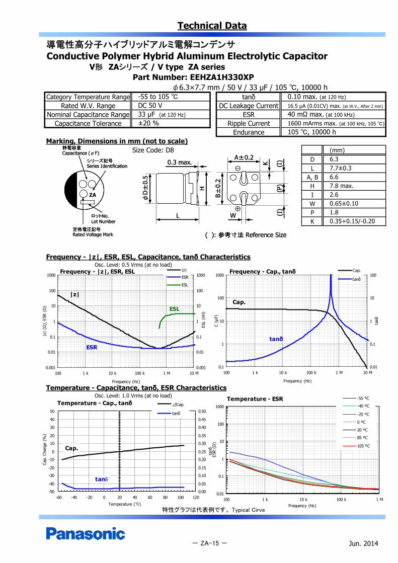
V形 ZAシリーズ / V type ZA seriesPart Number: EEHZA1H330XP
φ6.3×7.7 mm / 50 V / 33 μF / 105 , 10000 hCategory Temperature Range tanδ
Rated W.V. Range DC Leakage CurrentNominal Capacitance Range ESR
Capacitance Tolerance Ripple CurrentEndurance
Marking, Dimensions in mm (not to scale)Size Code: D8 (mm)
DL
A, BH
ZA IWPK
Frequency - |z|, ESR, ESL, Capacitance, tanδ CharacteristicsOsc. Level: 0.5 Vrms (at no load)
Temperature - Capacitance, tanδ, ESR CharacteristicsOsc. Level: 1.0 Vrms (at no load)
特性グラフは代表例です。 Typical Cirve
Jun. 2014- ZA-15 -
105 , 10000 h
0.10 max. (at 120 Hz)
16.5 µA (0.01CV) max. (at W.V., After 2 min)
40 mΩ max. (at 100 kHz)
1600 mArms max. (at 100 kHz, 105 )±20 %
-55 to 105 DC 50 V33 μF (at 120 Hz)
2.60.65±0.101.80.35+0.15/-0.20
6.37.7±0.36.67.8 max.
Frequency - Cap., tanδ
0.1
1
10
100
1000
100 1 k 10 k 100 k 1 M 10 M
Frequency (Hz)
C (μ
F)
0.01
0.1
1
10
100
tanδ
Cap.
tanδ
Cap.
tanδ
Temperature - ESR
0.01
0.1
1
10
100
1000
100 1 k 10 k 100 k 1 MFrequency (Hz)
ESR
(Ω)
-55 ºC
-40 ºC
-25 ºC
0 ºC
20 ºC
85 ºC
105 ºC
Frequency - |z|, ESR, ESL
0.001
0.01
0.1
1
10
100
1000
100 1 k 10 k 100 k 1 M 10 M
Frequency (Hz)
|z|
(Ω),
ESR
(Ω
)
0.001
0.01
0.1
1
10
100
1000
ESL
(nH
)
|z|
ESR
ESL
|z|
ESR
ESL
Temperature - Cap., tanδ
-50
-40
-30
-20
-10
0
10
20
30
40
50
-60 -40 -20 0 20 40 60 80 100 120
Temperature ()
Cap.
Cha
nge
(%)
0.00
0.05
0.10
0.15
0.20
0.25
0.30
0.35
0.40
0.45
0.50
tanδ
⊿Cap.
tanδ
Cap.
tan
静電容量Capacitance (μF)
シリーズ記号Series Identification
定格電圧記号Rated Voltage Mark
ロットNo.Lot Number
静電容量Capacitance (μF)
シリーズ記号Series Identification
定格電圧記号Rated Voltage Mark
ロットNo.Lot Number
K
A±0.2
( ): 参考寸法 Reference Size
(I)
B±0.
2
0.3 max.
H
L
φD
±0.
5
W
(P)
(I)
⊕
⊖
K
A±0.2
( ): 参考寸法 Reference Size
(I)
B±0.
2
0.3 max.
H
L
φD
±0.
5
W
(P)
(I)
⊕
⊖

Technical Data
導電性高分子ハイブリッドアルミ電解コンデンサConductive Polymer Hybrid Aluminum Electrolytic Capacitor
V形 ZAシリーズ / V type ZA seriesPart Number: EEHZA1H680P
φ8.0×10.2 mm / 50 V / 68 μF / 105 , 10000 hCategory Temperature Range tanδ
Rated W.V. Range DC Leakage CurrentNominal Capacitance Range ESR
Capacitance Tolerance Ripple CurrentEndurance
Marking, Dimensions in mm (not to scale)Size Code: F (mm)
DL
A, BH
ZA IWPK
Frequency - |z|, ESR, ESL, Capacitance, tanδ CharacteristicsOsc. Level: 0.5 Vrms (at no load)
Temperature - Capacitance, tanδ, ESR CharacteristicsOsc. Level: 1.0 Vrms (at no load)
特性グラフは代表例です。 Typical Cirve
Jun. 2014- ZA-16 -
105 , 10000 h±20 %
-55 to 105 DC 50 V68 μF (at 120 Hz)
0.1 max. (at 120 Hz)
34 µA (0.01CV) max. (at W.V., After 2 min)
30 mΩ max. (at 100 kHz)
1800 mArms max. (at 100 kHz, 105 )
3.40.9±0.23.10.7±0.2
8.010.2±0.38.310.0 max.
Frequency - |z|, ESR, ESL
0.001
0.01
0.1
1
10
100
1000
100 1 k 10 k 100 k 1 M 10 M
Frequency (Hz)
|z|
(Ω),
ESR
(Ω)
0.001
0.01
0.1
1
10
100
1000
ESL
(nH)
|z|
ESR
ESL
|z|
ESR
ESL
Frequency - Cap., tanδ
0.1
1
10
100
1000
100 1 k 10 k 100 k 1 M 10 M
Frequency (Hz)
C (μ
F)
0.01
0.1
1
10
100
tanδ
Cap.
tanδ
Cap.
tanδ
Temperature - Cap., tanδ
-50
-40
-30
-20
-10
0
10
20
30
40
50
-60 -40 -20 0 20 40 60 80 100 120
Temperature ()
Cap.
Cha
nge
(%)
0.00
0.05
0.10
0.15
0.20
0.25
0.30
0.35
0.40
0.45
0.50
tanδ
⊿Cap.
tanδ
Cap.
tan
Temperature - ESR
0.01
0.1
1
10
100
1000
100 1 k 10 k 100 k 1 MFrequency (Hz)
ESR
(Ω)
-55 ºC
-40 ºC
-25 ºC
0 ºC
20 ºC
85 ºC
105 ºC
静電容量Capacitance (μF)
シリーズ記号Series Identification
定格電圧記号Rated Voltage Mark
ロットNo.Lot Number
静電容量Capacitance (μF)
シリーズ記号Series Identification
定格電圧記号Rated Voltage Mark
ロットNo.Lot Number
K
A±0.2
( ): 参考寸法 Reference Size
(I)
B±0.
2
0.3 max.
H
L
φD
±0.
5
W
(P)
(I)
⊕
⊖
K
A±0.2
( ): 参考寸法 Reference Size
(I)
B±0.
2
0.3 max.
H
L
φD
±0.
5
W
(P)
(I)
⊕
⊖

Technical Data
導電性高分子ハイブリッドアルミ電解コンデンサConductive Polymer Hybrid Aluminum Electrolytic Capacitor
V形 ZAシリーズ / V type ZA seriesPart Number: EEHZA1H101P
φ10.0×10.2 mm / 50 V / 100 μF / 105 , 10000 hCategory Temperature Range tanδ
Rated W.V. Range DC Leakage CurrentNominal Capacitance Range ESR
Capacitance Tolerance Ripple CurrentEndurance
Marking, Dimensions in mm (not to scale)Size Code: G (mm)
DL
A, BH
ZA IWPK
Frequency - |z|, ESR, ESL, Capacitance, tanδ CharacteristicsOsc. Level: 0.5 Vrms (at no load)
Temperature - Capacitance, tanδ, ESR CharacteristicsOsc. Level: 1.0 Vrms (at no load)
特性グラフは代表例です。 Typical Cirve
Jun. 2014- ZA-17 -
105 , 10000 h±20 %
-55 to 105 DC 50 V100 μF (at 120 Hz)
0.1 max. (at 120 Hz)
50 µA (0.01CV) max. (at W.V., After 2 min)
28 mΩ max. (at 100 kHz)
2000 mArms max. (at 100 kHz, 105 )
3.50.9±0.24.60.7±0.2
10.010.2±0.310.312.0 max.
Frequency - Cap., tanδ
0.1
1
10
100
1000
100 1 k 10 k 100 k 1 M 10 M
Frequency (Hz)
C (μ
F)
0.01
0.1
1
10
100
tanδ
Cap.
tanδ
Cap.
tanδ
Temperature - Cap., tanδ
-50
-40
-30
-20
-10
0
10
20
30
40
50
-60 -40 -20 0 20 40 60 80 100 120
Temperature ()
Cap.
Cha
nge
(%)
0.00
0.05
0.10
0.15
0.20
0.25
0.30
0.35
0.40
0.45
0.50
tanδ
⊿Cap.
tanδ
Cap.
tan
Temperature - ESR
0.01
0.1
1
10
100
1000
100 1 k 10 k 100 k 1 MFrequency (Hz)
ESR
(Ω)
-55 ºC
-40 ºC
-25 ºC
0 ºC
20 ºC
85 ºC
105 ºC
Frequency - |z|, ESR, ESL
0.001
0.01
0.1
1
10
100
1000
100 1 k 10 k 100 k 1 M 10 M
Frequency (Hz)
|z|
(Ω),
ESR
(Ω
)
0.001
0.01
0.1
1
10
100
1000
ESL
(nH
)
|z|
ESR
ESL
|z|
ESR
ESL
静電容量Capacitance (μF)
シリーズ記号Series Identification
定格電圧記号Rated Voltage Mark
ロットNo.Lot Number
静電容量Capacitance (μF)
シリーズ記号Series Identification
定格電圧記号Rated Voltage Mark
ロットNo.Lot Number
K
A±0.2
( ): 参考寸法 Reference Size
(I)
B±0.
2
0.3 max.
H
L
φD
±0.
5
W
(P)
(I)
⊕
⊖
K
A±0.2
( ): 参考寸法 Reference Size
(I)
B±0.
2
0.3 max.
H
L
φD
±0.
5
W
(P)
(I)
⊕
⊖

Technical Data
導電性高分子ハイブリッドアルミ電解コンデンサConductive Polymer Hybrid Aluminum Electrolytic Capacitor
V形 ZAシリーズ / V type ZA seriesPart Number: EEHZA1J100P
φ6.3×5.8 mm / 63 V / 10 μF / 105 , 10000 hCategory Temperature Range tanδ
Rated W.V. Range DC Leakage CurrentNominal Capacitance Range ESR
Capacitance Tolerance Ripple CurrentEndurance
Marking, Dimensions in mm (not to scale)Size Code: D (mm)
DL
A, BH
ZA IWPK
Frequency - |z|, ESR, ESL, Capacitance, tanδ CharacteristicsOsc. Level: 0.5 Vrms (at no load)
Temperature - Capacitance, tanδ, ESR CharacteristicsOsc. Level: 1.0 Vrms (at no load)
特性グラフは代表例です。 Typical Cirve
Jun. 2014- ZA-18 -
105 , 10000 h±20 %
-55 to 105 DC 63 V10 μF (at 120 Hz)
0.08 max. (at 120 Hz)
6.3 µA (0.01CV) max. (at W.V., After 2 min)
120 mΩ max. (at 100 kHz)
1000 mArms max. (at 100 kHz, 105 )
2.60.65±0.101.80.35+0.15/-0.20
6.35.8±0.36.67.8 max.
Temperature - ESR
0.01
0.1
1
10
100
1000
100 1 k 10 k 100 k 1 MFrequency (Hz)
ESR
(Ω)
-55 ºC
-40 ºC
-25 ºC
0 ºC
20 ºC
85 ºC
105 ºC
Frequency - Cap., tanδ
0.1
1
10
100
1000
100 1 k 10 k 100 k 1 M 10 M
Frequency (Hz)
C (μ
F)
0.01
0.1
1
10
100
tanδ
Cap.
tanδ
Cap.
tanδ
Frequency - |z|, ESR, ESL
0.001
0.01
0.1
1
10
100
1000
100 1 k 10 k 100 k 1 M 10 M
Frequency (Hz)
|z|
(Ω),
ESR
(Ω
)
0.001
0.01
0.1
1
10
100
1000
ESL
(nH
)
|z|
ESR
ESL|z|
ESR
ESL
Temperature - Cap., tanδ
-50
-40
-30
-20
-10
0
10
20
30
40
50
-60 -40 -20 0 20 40 60 80 100 120
Temperature ()
Cap.
Cha
nge
(%)
0.00
0.05
0.10
0.15
0.20
0.25
0.30
0.35
0.40
0.45
0.50
tanδ
⊿Cap.
tanδ
Cap.
tan
静電容量Capacitance (μF)
シリーズ記号Series Identification
定格電圧記号Rated Voltage Mark
ロットNo.Lot Number
静電容量Capacitance (μF)
シリーズ記号Series Identification
定格電圧記号Rated Voltage Mark
ロットNo.Lot Number
K
A±0.2
( ): 参考寸法 Reference Size
(I)
B±0.
2
0.3 max.
H
L
φD
±0.
5
W
(P)
(I)
⊕
⊖
K
A±0.2
( ): 参考寸法 Reference Size
(I)
B±0.
2
0.3 max.
H
L
φD
±0.
5
W
(P)
(I)
⊕
⊖
Technical Data
導電性高分子ハイブリッドアルミ電解コンデンサConductive Polymer Hybrid Aluminum Electrolytic Capacitor
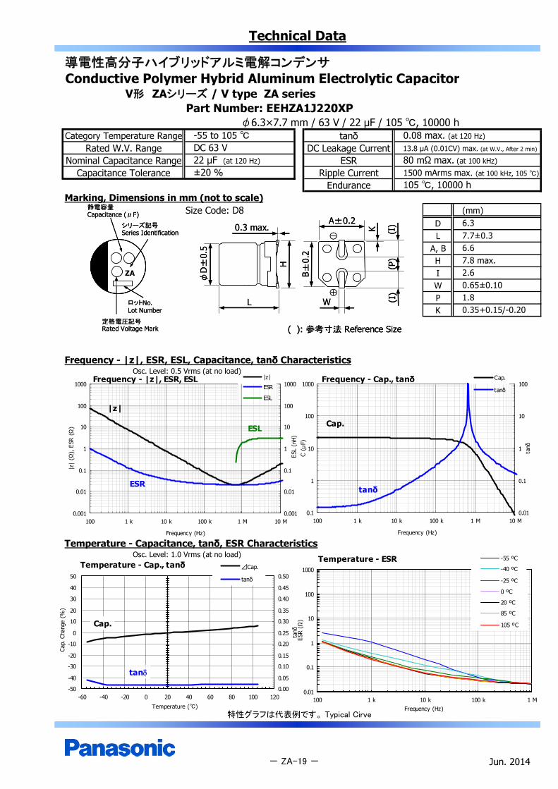
V形 ZAシリーズ / V type ZA seriesPart Number: EEHZA1J220XP
φ6.3×7.7 mm / 63 V / 22 μF / 105 , 10000 hCategory Temperature Range tanδ
Rated W.V. Range DC Leakage CurrentNominal Capacitance Range ESR
Capacitance Tolerance Ripple CurrentEndurance
Marking, Dimensions in mm (not to scale)Size Code: D8 (mm)
DL
A, BH
ZA IWPK
Frequency - |z|, ESR, ESL, Capacitance, tanδ CharacteristicsOsc. Level: 0.5 Vrms (at no load)
Temperature - Capacitance, tanδ, ESR CharacteristicsOsc. Level: 1.0 Vrms (at no load)
特性グラフは代表例です。 Typical Cirve
Jun. 2014- ZA-19 -
105 , 10000 h±20 %
-55 to 105 DC 63 V22 μF (at 120 Hz)
0.08 max. (at 120 Hz)
13.8 µA (0.01CV) max. (at W.V., After 2 min)
80 mΩ max. (at 100 kHz)
1500 mArms max. (at 100 kHz, 105 )
2.60.65±0.101.80.35+0.15/-0.20
6.37.7±0.36.67.8 max.
Frequency - Cap., tanδ
0.1
1
10
100
1000
100 1 k 10 k 100 k 1 M 10 M
Frequency (Hz)
C (μ
F)
0.01
0.1
1
10
100
tanδ
Cap.
tanδ
Cap.
tanδ
Frequency - |z|, ESR, ESL
0.001
0.01
0.1
1
10
100
1000
100 1 k 10 k 100 k 1 M 10 M
Frequency (Hz)
|z|
(Ω),
ESR
(Ω)
0.001
0.01
0.1
1
10
100
1000
ESL
(nH)
|z|
ESR
ESL
|z|
ESR
ESL
Temperature - Cap., tanδ
-50
-40
-30
-20
-10
0
10
20
30
40
50
-60 -40 -20 0 20 40 60 80 100 120
Temperature ()
Cap.
Cha
nge
(%)
0.00
0.05
0.10
0.15
0.20
0.25
0.30
0.35
0.40
0.45
0.50
tanδ
⊿Cap.
tanδ
Cap.
tan
Temperature - ESR
0.01
0.1
1
10
100
1000
100 1 k 10 k 100 k 1 MFrequency (Hz)
ESR
(Ω)
-55 ºC
-40 ºC
-25 ºC
0 ºC
20 ºC
85 ºC
105 ºC
静電容量Capacitance (μF)
シリーズ記号Series Identification
定格電圧記号Rated Voltage Mark
ロットNo.Lot Number
静電容量Capacitance (μF)
シリーズ記号Series Identification
定格電圧記号Rated Voltage Mark
ロットNo.Lot Number
K
A±0.2
( ): 参考寸法 Reference Size
(I)
B±0.
2
0.3 max.
H
L
φD
±0.
5
W
(P)
(I)
⊕
⊖
K
A±0.2
( ): 参考寸法 Reference Size
(I)
B±0.
2
0.3 max.
H
L
φD
±0.
5
W
(P)
(I)
⊕
⊖
Technical Data
導電性高分子ハイブリッドアルミ電解コンデンサConductive Polymer Hybrid Aluminum Electrolytic Capacitor
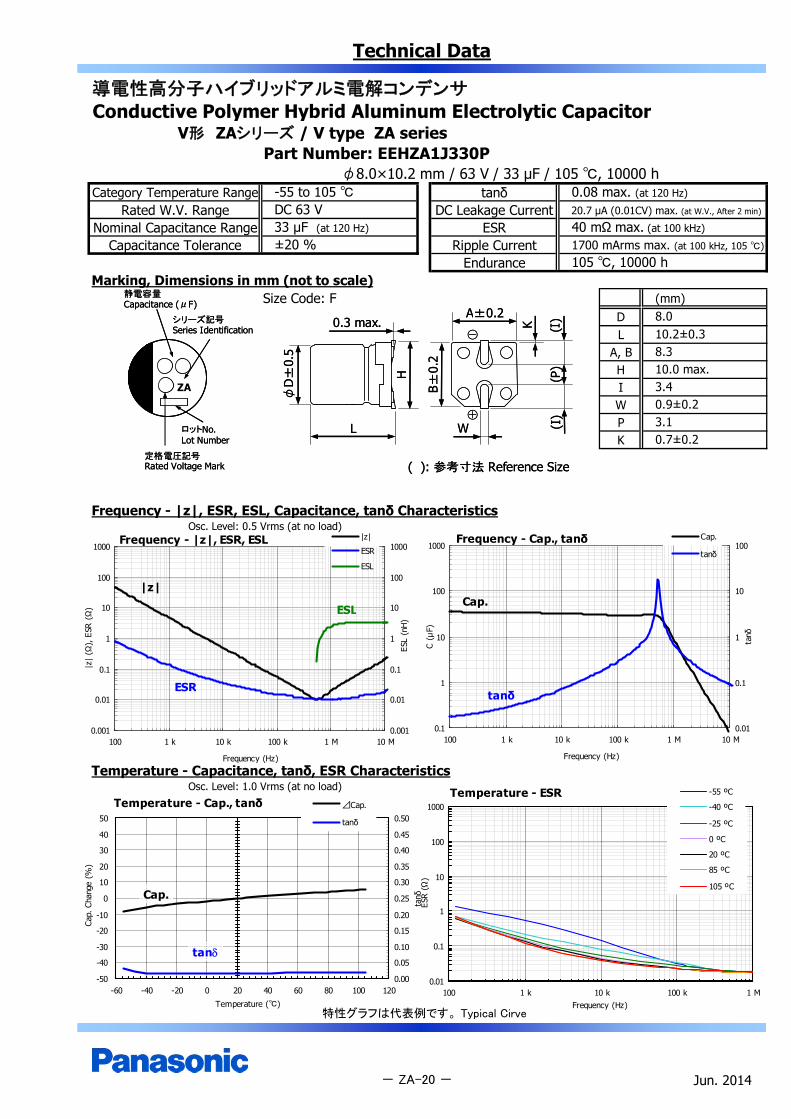
V形 ZAシリーズ / V type ZA seriesPart Number: EEHZA1J330P
φ8.0×10.2 mm / 63 V / 33 μF / 105 , 10000 hCategory Temperature Range tanδ
Rated W.V. Range DC Leakage CurrentNominal Capacitance Range ESR
Capacitance Tolerance Ripple CurrentEndurance
Marking, Dimensions in mm (not to scale)Size Code: F (mm)
DL
A, BH
ZA IWPK
Frequency - |z|, ESR, ESL, Capacitance, tanδ CharacteristicsOsc. Level: 0.5 Vrms (at no load)
Temperature - Capacitance, tanδ, ESR CharacteristicsOsc. Level: 1.0 Vrms (at no load)
特性グラフは代表例です。 Typical Cirve
Jun. 2014
8.010.2±0.38.310.0 max.
- ZA-20 -
3.40.9±0.23.10.7±0.2
105 , 10000 h±20 %
-55 to 105 DC 63 V33 μF (at 120 Hz)
0.08 max. (at 120 Hz)
20.7 µA (0.01CV) max. (at W.V., After 2 min)
40 mΩ max. (at 100 kHz)
1700 mArms max. (at 100 kHz, 105 )
Frequency - Cap., tanδ
0.1
1
10
100
1000
100 1 k 10 k 100 k 1 M 10 M
Frequency (Hz)
C (μ
F)
0.01
0.1
1
10
100
tanδ
Cap.
tanδ
Cap.
tanδ
Temperature - Cap., tanδ
-50
-40
-30
-20
-10
0
10
20
30
40
50
-60 -40 -20 0 20 40 60 80 100 120
Temperature ()
Cap.
Cha
nge
(%)
0.00
0.05
0.10
0.15
0.20
0.25
0.30
0.35
0.40
0.45
0.50
tanδ
⊿Cap.
tanδ
Cap.
tan
Temperature - ESR
0.01
0.1
1
10
100
1000
100 1 k 10 k 100 k 1 MFrequency (Hz)
ESR
(Ω)
-55 ºC
-40 ºC
-25 ºC
0 ºC
20 ºC
85 ºC
105 ºC
Frequency - |z|, ESR, ESL
0.001
0.01
0.1
1
10
100
1000
100 1 k 10 k 100 k 1 M 10 M
Frequency (Hz)
|z|
(Ω),
ESR
(Ω
)
0.001
0.01
0.1
1
10
100
1000
ESL
(nH
)
|z|
ESR
ESL
|z|
ESR
ESL
静電容量Capacitance (μF)
シリーズ記号Series Identification
定格電圧記号Rated Voltage Mark
ロットNo.Lot Number
静電容量Capacitance (μF)
シリーズ記号Series Identification
定格電圧記号Rated Voltage Mark
ロットNo.Lot Number
K
A±0.2
( ): 参考寸法 Reference Size
(I)
B±0.
2
0.3 max.
H
L
φD
±0.
5
W
(P)
(I)
⊕
⊖
K
A±0.2
( ): 参考寸法 Reference Size
(I)
B±0.
2
0.3 max.
H
L
φD
±0.
5
W
(P)
(I)
⊕
⊖

Technical Data
導電性高分子ハイブリッドアルミ電解コンデンサConductive Polymer Hybrid Aluminum Electrolytic Capacitor
V形 ZAシリーズ / V type ZA seriesPart Number: EEHZA1J560P
φ10.0×10.2 mm / 63 V / 56 μF / 105 , 10000 hCategory Temperature Range tanδ
Rated W.V. Range DC Leakage CurrentNominal Capacitance Range ESR
Capacitance Tolerance Ripple CurrentEndurance
Marking, Dimensions in mm (not to scale)Size Code: G (mm)
DL
A, BH
ZA IWPK
Frequency - |z|, ESR, ESL, Capacitance, tanδ CharacteristicsOsc. Level: 0.5 Vrms (at no load)
Temperature - Capacitance, tanδ, ESR CharacteristicsOsc. Level: 1.0 Vrms (at no load)
特性グラフは代表例です。 Typical Cirve
Jun. 2014- ZA-21 -
105 , 10000 h±20 %
-55 to 105 DC 63 V56 μF (at 120 Hz)
0.08 max. (at 120 Hz)
35.2 µA (0.01CV) max. (at W.V., After 2 min)
30 mΩ max. (at 100 kHz)
1800 mArms max. (at 100 kHz, 105 )
3.50.9±0.24.60.7±0.2
10.010.2±0.310.312.0 max.
Frequency - Cap., tanδ
0.1
1
10
100
1000
100 1 k 10 k 100 k 1 M 10 M
Frequency (Hz)
C (μ
F)
0.01
0.1
1
10
100
tanδ
Cap.
tanδ
Cap.
tanδ
Temperature - ESR
0.01
0.1
1
10
100
1000
100 1 k 10 k 100 k 1 MFrequency (Hz)
ESR
(Ω)
-55 ºC
-40 ºC
-25 ºC
0 ºC
20 ºC
85 ºC
105 ºC
C
Frequency - |z|, ESR, ESL
0.001
0.01
0.1
1
10
100
1000
100 1 k 10 k 100 k 1 M 10 M
Frequency (Hz)
|z|
(Ω),
ESR
(Ω
)
0.001
0.01
0.1
1
10
100
1000
ESL
(nH
)
|z|
ESR
ESL
|z|
ESR
ESL
Temperature - Cap., tanδ
-50
-40
-30
-20
-10
0
10
20
30
40
50
-60 -40 -20 0 20 40 60 80 100 120
Temperature ()
Cap.
Cha
nge
(%)
0.00
0.05
0.10
0.15
0.20
0.25
0.30
0.35
0.40
0.45
0.50
tanδ
⊿Cap.
tanδ
Cap.
tan
静電容量Capacitance (μF)
シリーズ記号Series Identification
定格電圧記号Rated Voltage Mark
ロットNo.Lot Number
静電容量Capacitance (μF)
シリーズ記号Series Identification
定格電圧記号Rated Voltage Mark
ロットNo.Lot Number
K
A±0.2
( ): 参考寸法 Reference Size
(I)
B±0.
2
0.3 max.
H
L
φD
±0.
5
W
(P)
(I)
⊕
⊖
K
A±0.2
( ): 参考寸法 Reference Size
(I)
B±0.
2
0.3 max.
H
L
φD
±0.
5
W
(P)
(I)
⊕
⊖

Technical Data
導電性高分子ハイブリッドアルミ電解コンデンサConductive Polymer Hybrid Aluminum Electrolytic Capacitor
V形 ZAシリーズ / V type ZA seriesPart Number: EEHZA1K220P
φ8.0×10.2 mm / 80 V / 22 μF / 105 , 10000 hCategory Temperature Range tanδ
Rated W.V. Range DC Leakage CurrentNominal Capacitance Range ESR
Capacitance Tolerance Ripple CurrentEndurance
Marking, Dimensions in mm (not to scale)Size Code: F (mm)
DL
A, BH
ZA IWPK
Frequency - |z|, ESR, ESL, Capacitance, tanδ CharacteristicsOsc. Level: 0.5 Vrms (at no load)
Temperature - Capacitance, tanδ, ESR CharacteristicsOsc. Level: 1.0 Vrms (at no load)
特性グラフは代表例です。 Typical Cirve
Jun. 2014- ZA-22 -
105 , 10000 h±20 %
-55 to 105 DC 80 V22 μF (at 120 Hz)
0.08 max. (at 120 Hz)
17.6 µA (0.01CV) max. (at W.V., After 2 min)
45 mΩ max. (at 100 kHz)
1550 mArms max. (at 100 kHz, 105 )
3.40.9±0.23.10.7±0.2
8.010.2±0.38.310.0 max.
Temperature - Cap., tanδ
-50
-40
-30
-20
-10
0
10
20
30
40
50
-60 -40 -20 0 20 40 60 80 100 120
Temperature ()
Cap.
Cha
nge
(%)
0.00
0.05
0.10
0.15
0.20
0.25
0.30
0.35
0.40
0.45
0.50
tanδ
⊿Cap.
tanδ
Cap.
tan
Temperature - ESR
0.01
0.1
1
10
100
1000
100 1 k 10 k 100 k 1 MFrequency (Hz)
ESR
(Ω)
-55 ºC
-40 ºC
-25 ºC
0 ºC
20 ºC
85 ºC
105 ºC
Frequency - |z|, ESR, ESL
0.001
0.01
0.1
1
10
100
1000
100 1 k 10 k 100 k 1 M 10 M
Frequency (Hz)
|z|
(Ω),
ESR
(Ω
)
0.001
0.01
0.1
1
10
100
1000
ESL
(nH
)
|z|
ESR
ESL|z|
ESR
ESL
Frequency - Cap., tanδ
0.1
1
10
100
1000
100 1 k 10 k 100 k 1 M 10 M
Frequency (Hz)
C (μ
F)
0.01
0.1
1
10
100
tanδ
Cap.
tanδ
Cap.
tanδ
静電容量Capacitance (μF)
シリーズ記号Series Identification
定格電圧記号Rated Voltage Mark
ロットNo.Lot Number
静電容量Capacitance (μF)
シリーズ記号Series Identification
定格電圧記号Rated Voltage Mark
ロットNo.Lot Number
K
A±0.2
( ): 参考寸法 Reference Size
(I)
B±0.
2
0.3 max.
H
L
φD
±0.
5
W
(P)
(I)
⊕
⊖
K
A±0.2
( ): 参考寸法 Reference Size
(I)
B±0.
2
0.3 max.
H
L
φD
±0.
5
W
(P)
(I)
⊕
⊖

Technical Data
導電性高分子ハイブリッドアルミ電解コンデンサConductive Polymer Hybrid Aluminum Electrolytic Capacitor
V形 ZAシリーズ / V type ZA seriesPart Number: EEHZA1K330P
φ10.0×10.2 mm / 80 V / 33 μF / 105 , 10000 hCategory Temperature Range tanδ
Rated W.V. Range DC Leakage CurrentNominal Capacitance Range ESR
Capacitance Tolerance Ripple CurrentEndurance
Marking, Dimensions in mm (not to scale)Size Code: G (mm)
DL
A, BH
ZA IWPK
Frequency - |z|, ESR, ESL, Capacitance, tanδ CharacteristicsOsc. Level: 0.5 Vrms (at no load)
Temperature - Capacitance, tanδ, ESR CharacteristicsOsc. Level: 1.0 Vrms (at no load)
特性グラフは代表例です。 Typical Cirve
Jun. 2014- ZA-23 -
105 , 10000 h±20 %
-55 to 105 DC 80 V33 μF (at 120 Hz)
0.08 max. (at 120 Hz)
26.4 µA (0.01CV) max. (at W.V., After 2 min)
36 mΩ max. (at 100 kHz)
1700 mArms max. (at 100 kHz, 105 )
3.50.9±0.24.60.7±0.2
10.010.2±0.310.312.0 max.
Temperature - Cap., tanδ
-50
-40
-30
-20
-10
0
10
20
30
40
50
-60 -40 -20 0 20 40 60 80 100 120
Temperature ()
Cap.
Cha
nge
(%)
0.00
0.05
0.10
0.15
0.20
0.25
0.30
0.35
0.40
0.45
0.50
tanδ
⊿Cap.
tanδ
Cap.
tan
Temperature - ESR
0.01
0.1
1
10
100
1000
100 1 k 10 k 100 k 1 MFrequency (Hz)
ESR
(Ω)
-55 ºC
-40 ºC
-25 ºC
0 ºC
20 ºC
85 ºC
105 ºC
Frequency - |z|, ESR, ESL
0.001
0.01
0.1
1
10
100
1000
100 1 k 10 k 100 k 1 M 10 M
Frequency (Hz)
|z|
(Ω),
ESR
(Ω)
0.001
0.01
0.1
1
10
100
1000
ESL
(nH)
|z|
ESR
ESL
|z|
ESR
ESL
Frequency - Cap., tanδ
0.1
1
10
100
1000
100 1 k 10 k 100 k 1 M 10 M
Frequency (Hz)
C (μ
F)
0.01
0.1
1
10
100
tanδ
Cap.
tanδ
Cap.
tanδ
静電容量Capacitance (μF)
シリーズ記号Series Identification
定格電圧記号Rated Voltage Mark
ロットNo.Lot Number
静電容量Capacitance (μF)
シリーズ記号Series Identification
定格電圧記号Rated Voltage Mark
ロットNo.Lot Number
K
A±0.2
( ): 参考寸法 Reference Size
(I)
B±0.
2
0.3 max.
H
L
φD
±0.
5
W
(P)
(I)
⊕
⊖
K
A±0.2
( ): 参考寸法 Reference Size
(I)
B±0.
2
0.3 max.
H
L
φD
±0.
5
W
(P)
(I)
⊕
⊖
Technical Data
導電性高分子ハイブリッドアルミ電解コンデンサConductive Polymer Hybrid Aluminum Electrolytic Capacitor
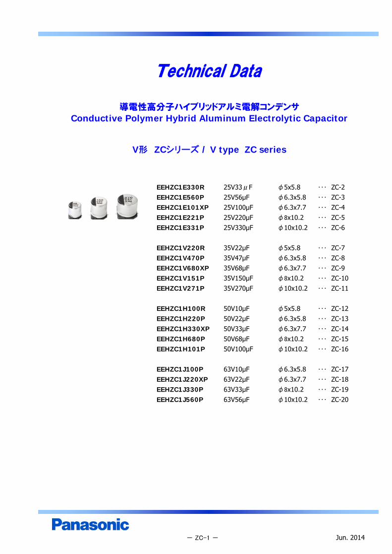
V形 ZCシリーズ / V type ZC series
EEHZC1E330R 25V33μF φ5x5.8 ・・・ ZC-2EEHZC1E560P 25V56μF φ6.3x5.8 ・・・ ZC-3EEHZC1E101XP 25V100μF φ6.3x7.7 ・・・ ZC-4EEHZC1E221P 25V220μF φ8x10.2 ・・・ ZC-5EEHZC1E331P 25V330μF φ10x10.2 ・・・ ZC-6
EEHZC1V220R 35V22μF φ5x5.8 ・・・ ZC-7EEHZC1V470P 35V47μF φ6.3x5.8 ・・・ ZC-8EEHZC1V680XP 35V68μF φ6.3x7.7 ・・・ ZC-9EEHZC1V151P 35V150μF φ8x10.2 ・・・ ZC-10EEHZC1V271P 35V270μF φ10x10.2 ・・・ ZC-11
EEHZC1H100R 50V10μF φ5x5.8 ・・・ ZC-12EEHZC1H220P 50V22μF φ6.3x5.8 ・・・ ZC-13EEHZC1H330XP 50V33μF φ6.3x7.7 ・・・ ZC-14EEHZC1H680P 50V68μF φ8x10.2 ・・・ ZC-15EEHZC1H101P 50V100μF φ10x10.2 ・・・ ZC-16
EEHZC1J100P 63V10μF φ6.3x5.8 ・・・ ZC-17EEHZC1J220XP 63V22μF φ6.3x7.7 ・・・ ZC-18EEHZC1J330P 63V33μF φ8x10.2 ・・・ ZC-19EEHZC1J560P 63V56μF φ10x10.2 ・・・ ZC-20
- ZC-1 - Jun. 2014

Technical Data
導電性高分子ハイブリッドアルミ電解コンデンサConductive Polymer Hybrid Aluminum Electrolytic Capacitor
V形 ZCシリーズ / V type ZC seriesPart Number: EEHZC1E330R
φ5.0×5.8 mm / 25 V / 33 μF / 125 , 4000 hCategory Temperature Range tanδ
Rated W.V. Range DC Leakage CurrentNominal Capacitance Range ESR
Capacitance Tolerance Ripple CurrentEndurance
Marking, Dimensions in mm (not to scale)Size Code: C (mm)
DL
A, BH
ZC IWPK
Frequency - |z|, ESR, ESL, Capacitance, tanδ CharacteristicsOsc. Level: 0.5 Vrms (at no load)
Temperature - Capacitance, tanδ, ESR CharacteristicsOsc. Level: 1.0 Vrms (at no load)
特性グラフは代表例です。 Typical Cirve
Jun. 2014
125 , 4000 h
0.14 max. (at 120 Hz)
8.2 µA (0.01CV) max. (at W.V., After 2 min)
80 mΩ max. (at 100 kHz)
550 mArms max. (at 100 kHz, 125 )±20 %
-55 to 125 DC 25 V33 μF (at 120 Hz)
1.50.35+0.15/-0.20
- ZC-2 -
5.05.8±0.35.36.5 max.2.20.65±0.10
Frequency - Cap., tanδ
0.1
1
10
100
1000
100 1 k 10 k 100 k 1 M 10 M
Frequency (Hz)
C (μ
F)
0.01
0.1
1
10
100
tanδ
Cap.
tanδ
Cap.
tanδ
Temperature - Cap., tanδ
-50
-40
-30
-20
-10
0
10
20
30
40
50
-60 -40 -20 0 20 40 60 80 100 120 140
Temperature ()
Cap.
Cha
nge
(%)
0.00
0.05
0.10
0.15
0.20
0.25
0.30
0.35
0.40
0.45
0.50
tanδ
⊿Cap.
tanδ
Temperature - ESR
0.01
0.1
1
10
100
1000
100 1 k 10 k 100 k 1 MFrequency (Hz)
ESR
(Ω)
-55 ºC
-40 ºC
-25 ºC
0 ºC
20 ºC
85 ºC
105 ºC
125 ºC
Frequency - |z|, ESR, ESL
0.001
0.01
0.1
1
10
100
1000
100 1 k 10 k 100 k 1 M 10 M
Frequency (Hz)
|z|
(Ω),
ESR
(Ω)
0.001
0.01
0.1
1
10
100
1000
ESL
(nH)
|z|
ESR
ESL
|z|
ESR
ESL
静電容量Capacitance (μF)
シリーズ記号Series Identification
定格電圧記号Rated Voltage Mark
ロットNo.Lot Number
静電容量Capacitance (μF)
シリーズ記号Series Identification
定格電圧記号Rated Voltage Mark
ロットNo.Lot Number
K
A±0.2
( ): 参考寸法 Reference Size
(I)
B±0.
2
0.3 max.
H
L
φD
±0.
5
W
(P)
(I)
⊕
⊖
K
A±0.2
( ): 参考寸法 Reference Size
(I)
B±0.
2
0.3 max.
H
L
φD
±0.
5
W
(P)
(I)
⊕
⊖

Technical Data
導電性高分子ハイブリッドアルミ電解コンデンサConductive Polymer Hybrid Aluminum Electrolytic Capacitor
V形 ZCシリーズ / V type ZC seriesPart Number: EEHZC1E560P
φ6.3×5.8 mm / 25 V / 56 μF / 125 , 4000 hCategory Temperature Range tanδ
Rated W.V. Range DC Leakage CurrentNominal Capacitance Range ESR
Capacitance Tolerance Ripple CurrentEndurance
Marking, Dimensions in mm (not to scale)Size Code: D (mm)
DL
A, BH
ZC IWPK
Frequency - |z|, ESR, ESL, Capacitance, tanδ CharacteristicsOsc. Level: 0.5 Vrms (at no load)
Temperature - Capacitance, tanδ, ESR CharacteristicsOsc. Level: 1.0 Vrms (at no load)
特性グラフは代表例です。 Typical Cirve
Jun. 2014- ZC-3 -
125 , 4000 h±20 %
-55 to 125 DC 25 V56 μF (at 120 Hz)
0.14 max. (at 120 Hz)
14 µA (0.01CV) max. (at W.V., After 2 min)
50 mΩ max. (at 100 kHz)
900 mArms max. (at 100 kHz, 125 )
1.80.35+0.15/-0.20
6.35.8±0.36.67.8 max.2.60.65±0.10
Frequency - Cap., tanδ
0.1
1
10
100
1000
100 1 k 10 k 100 k 1 M 10 M
Frequency (Hz)
C (μ
F)
0.01
0.1
1
10
100
tanδ
Cap.
tanδ
Cap.
tanδ
Temperature - ESR
0.01
0.1
1
10
100
1000
100 1 k 10 k 100 k 1 MFrequency (Hz)
ESR
(Ω)
-55 ºC
-40 ºC
-25 ºC
0 ºC
20 ºC
85 ºC
105 ºC
125 ºC
Frequency - |z|, ESR, ESL
0.001
0.01
0.1
1
10
100
1000
100 1 k 10 k 100 k 1 M 10 M
Frequency (Hz)
|z|
(Ω),
ESR
(Ω
)
0.001
0.01
0.1
1
10
100
1000
ESL
(nH
)
|z|
ESR
ESL
|z|
ESR
ESL
Temperature - Cap., tanδ
-50
-40
-30
-20
-10
0
10
20
30
40
50
-60 -40 -20 0 20 40 60 80 100 120 140
Temperature ()
Cap.
Cha
nge
(%)
0.00
0.05
0.10
0.15
0.20
0.25
0.30
0.35
0.40
0.45
0.50
tanδ
⊿Cap.
tanδ
静電容量Capacitance (μF)
シリーズ記号Series Identification
定格電圧記号Rated Voltage Mark
ロットNo.Lot Number
静電容量Capacitance (μF)
シリーズ記号Series Identification
定格電圧記号Rated Voltage Mark
ロットNo.Lot Number
K
A±0.2
( ): 参考寸法 Reference Size
(I)
B±0.
2
0.3 max.
H
L
φD
±0.
5
W
(P)
(I)
⊕
⊖
K
A±0.2
( ): 参考寸法 Reference Size
(I)
B±0.
2
0.3 max.
H
L
φD
±0.
5
W
(P)
(I)
⊕
⊖

Technical Data
導電性高分子ハイブリッドアルミ電解コンデンサConductive Polymer Hybrid Aluminum Electrolytic Capacitor
V形 ZCシリーズ / V type ZC seriesPart Number: EEHZC1E101XP
φ6.3×7.7 mm / 25 V / 100 μF / 125 , 4000 hCategory Temperature Range tanδ
Rated W.V. Range DC Leakage CurrentNominal Capacitance Range ESR
Capacitance Tolerance Ripple CurrentEndurance
Marking, Dimensions in mm (not to scale)Size Code: D8 (mm)
DL
A, BH
ZC IWPK
Frequency - |z|, ESR, ESL, Capacitance, tanδ CharacteristicsOsc. Level: 0.5 Vrms (at no load)
Temperature - Capacitance, tanδ, ESR CharacteristicsOsc. Level: 1.0 Vrms (at no load)
特性グラフは代表例です。 Typical Cirve
Jun. 2014- ZC-4 -
2.60.65±0.101.80.35+0.15/-0.20
6.35.8±0.36.67.8 max.
±20 %
-55 to 125 DC 25 V100 μF (at 120 Hz)
125 , 4000 h
0.12 max. (at 120 Hz)
25 µA (0.01CV) max. (at W.V., After 2 min)
30 mΩ max. (at 100 kHz)
1400 mArms max. (at 100 kHz, 125 )
Frequency - Cap., tanδ
0.1
1
10
100
1000
100 1 k 10 k 100 k 1 M 10 M
Frequency (Hz)
C (μ
F)
0.01
0.1
1
10
100
tanδ
Cap.
tanδ
Cap.
tanδ
Frequency - |z|, ESR, ESL
0.001
0.01
0.1
1
10
100
1000
100 1 k 10 k 100 k 1 M 10 M
Frequency (Hz)
|z|
(Ω),
ESR
(Ω)
0.001
0.01
0.1
1
10
100
1000
ESL
(nH)
|z|
ESR
ESL
|z|
ESR
ESL
Temperature - Cap., tanδ
-50
-40
-30
-20
-10
0
10
20
30
40
50
-60 -40 -20 0 20 40 60 80 100 120 140
Temperature ()
Cap.
Cha
nge
(%)
0.00
0.05
0.10
0.15
0.20
0.25
0.30
0.35
0.40
0.45
0.50
tanδ
⊿Cap.
tanδ
Temperature - ESR
0.01
0.1
1
10
100
1000
100 1 k 10 k 100 k 1 MFrequency (Hz)
ESR
(Ω)
-55 ºC
-40 ºC
-25 ºC
0 ºC
20 ºC
85 ºC
105 ºC
125 ºC
静電容量Capacitance (μF)
シリーズ記号Series Identification
定格電圧記号Rated Voltage Mark
ロットNo.Lot Number
静電容量Capacitance (μF)
シリーズ記号Series Identification
定格電圧記号Rated Voltage Mark
ロットNo.Lot Number
K
A±0.2
( ): 参考寸法 Reference Size
(I)
B±0.
2
0.3 max.
H
L
φD
±0.
5
W
(P)
(I)
⊕
⊖
K
A±0.2
( ): 参考寸法 Reference Size
(I)
B±0.
2
0.3 max.
H
L
φD
±0.
5
W
(P)
(I)
⊕
⊖
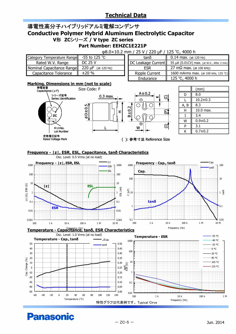
Technical Data
導電性高分子ハイブリッドアルミ電解コンデンサConductive Polymer Hybrid Aluminum Electrolytic Capacitor
V形 ZCシリーズ / V type ZC seriesPart Number: EEHZC1E221P
φ8.0×10.2 mm / 25 V / 220 μF / 125 , 4000 hCategory Temperature Range tanδ
Rated W.V. Range DC Leakage CurrentNominal Capacitance Range ESR
Capacitance Tolerance Ripple CurrentEndurance
Marking, Dimensions in mm (not to scale)Size Code: F (mm)
DL
A, BH
ZC IWPK
Frequency - |z|, ESR, ESL, Capacitance, tanδ CharacteristicsOsc. Level: 0.5 Vrms (at no load)
Temperature - Capacitance, tanδ, ESR CharacteristicsOsc. Level: 1.0 Vrms (at no load)
特性グラフは代表例です。 Typical Cirve
Jun. 2014- ZC-5 -
125 , 4000 h
0.14 max. (at 120 Hz)
55 µA (0.01CV) max. (at W.V., After 2 min)
27 mΩ max. (at 100 kHz)
1600 mArms max. (at 100 kHz, 125 )±20 %
-55 to 125 DC 25 V220 μF (at 120 Hz)
3.10.7±0.2
8.010.2±0.38.310.0 max.3.40.9±0.2
Temperature - ESR
0.01
0.1
1
10
100
1000
100 1 k 10 k 100 k 1 MFrequency (Hz)
ESR
(Ω)
-55 ºC
-40 ºC
-25 ºC
0 ºC
20 ºC
85 ºC
105 ºC
125 ºC
Frequency - |z|, ESR, ESL
0.001
0.01
0.1
1
10
100
1000
100 1 k 10 k 100 k 1 M 10 M
Frequency (Hz)
|z|
(Ω),
ESR
(Ω)
0.001
0.01
0.1
1
10
100
1000
ESL
(nH)
|z|
ESR
ESL
|z|
ESR
ESL
Frequency - Cap., tanδ
0.1
1
10
100
1000
100 1 k 10 k 100 k 1 M 10 M
Frequency (Hz)
C (μ
F)
0.01
0.1
1
10
100
tanδ
Cap.
tanδ
Cap.
tanδ
Temperature - Cap., tanδ
-50
-40
-30
-20
-10
0
10
20
30
40
50
-60 -40 -20 0 20 40 60 80 100 120 140
Temperature ()
Cap.
Cha
nge
(%)
0.00
0.05
0.10
0.15
0.20
0.25
0.30
0.35
0.40
0.45
0.50
tanδ
⊿Cap.
tanδ
静電容量Capacitance (μF)
シリーズ記号Series Identification
定格電圧記号Rated Voltage Mark
ロットNo.Lot Number
静電容量Capacitance (μF)
シリーズ記号Series Identification
定格電圧記号Rated Voltage Mark
ロットNo.Lot Number
K
A±0.2
( ): 参考寸法 Reference Size
(I)
B±0.
2
0.3 max.
H
L
φD
±0.
5
W
(P)
(I)
⊕
⊖
K
A±0.2
( ): 参考寸法 Reference Size
(I)
B±0.
2
0.3 max.
H
L
φD
±0.
5
W
(P)
(I)
⊕
⊖

Technical Data
導電性高分子ハイブリッドアルミ電解コンデンサConductive Polymer Hybrid Aluminum Electrolytic Capacitor
V形 ZCシリーズ / V type ZC seriesPart Number: EEHZC1E331P
φ10.0×10.2 mm / 25 V / 330 μF / 125 , 4000 hCategory Temperature Range tanδ
Rated W.V. Range DC Leakage CurrentNominal Capacitance Range ESR
Capacitance Tolerance Ripple CurrentEndurance
Marking, Dimensions in mm (not to scale)Size Code: G (mm)
DL
A, BH
ZC IWPK
Frequency - |z|, ESR, ESL, Capacitance, tanδ CharacteristicsOsc. Level: 0.5 Vrms (at no load)
Temperature - Capacitance, tanδ, ESR CharacteristicsOsc. Level: 1.0 Vrms (at no load)
特性グラフは代表例です。 Typical Cirve
Jun. 2014- ZC-6 -
3.50.9±0.24.60.7±0.2
10.010.2±0.310.312.0 max.
125 , 4000 h±20 %
-55 to 125 DC 25 V330 μF (at 120 Hz)
0.14 max. (at 120 Hz)
82.5 µA (0.01CV) max. (at W.V., After 2 min)
20 mΩ max. (at 100 kHz)
2000 mArms max. (at 100 kHz, 125 )
Frequency - Cap., tanδ
0.1
1
10
100
1000
100 1 k 10 k 100 k 1 M 10 M
Frequency (Hz)
C (μ
F)
0.01
0.1
1
10
100
tanδ
Cap.
tanδ
Cap.
tanδ
Temperature - ESR
0.01
0.1
1
10
100
1000
100 1 k 10 k 100 k 1 MFrequency (Hz)
ESR
(Ω)
-55 ºC
-40 ºC
-25 ºC
0 ºC
20 ºC
85 ºC
105 ºC
125 ºC
Frequency - |z|, ESR, ESL
0.001
0.01
0.1
1
10
100
1000
100 1 k 10 k 100 k 1 M 10 M
Frequency (Hz)
|z|
(Ω),
ESR
(Ω
)
0.001
0.01
0.1
1
10
100
1000
ESL
(nH
)
|z|
ESR
ESL
|z|
ESR
ESL
Temperature - Cap., tanδ
-50
-40
-30
-20
-10
0
10
20
30
40
50
-60 -40 -20 0 20 40 60 80 100 120 140
Temperature ()
Cap.
Cha
nge
(%)
0.00
0.05
0.10
0.15
0.20
0.25
0.30
0.35
0.40
0.45
0.50
tanδ
⊿Cap.
tanδ
Cap.
tan
静電容量Capacitance (μF)
シリーズ記号Series Identification
定格電圧記号Rated Voltage Mark
ロットNo.Lot Number
静電容量Capacitance (μF)
シリーズ記号Series Identification
定格電圧記号Rated Voltage Mark
ロットNo.Lot Number
K
A±0.2
( ): 参考寸法 Reference Size
(I)
B±0.
2
0.3 max.
H
L
φD
±0.
5
W
(P)
(I)
⊕
⊖
K
A±0.2
( ): 参考寸法 Reference Size
(I)
B±0.
2
0.3 max.
H
L
φD
±0.
5
W
(P)
(I)
⊕
⊖
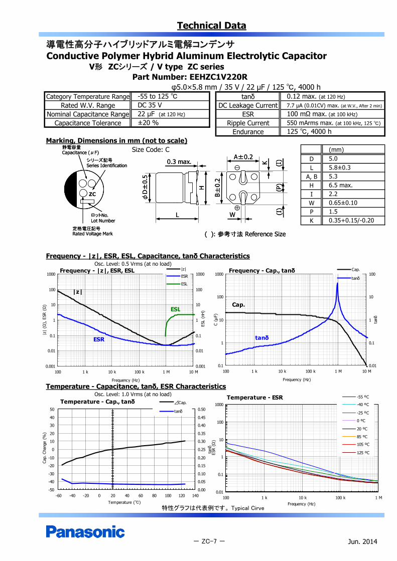
Technical Data
導電性高分子ハイブリッドアルミ電解コンデンサConductive Polymer Hybrid Aluminum Electrolytic Capacitor
V形 ZCシリーズ / V type ZC seriesPart Number: EEHZC1V220R
φ5.0×5.8 mm / 35 V / 22 μF / 125 , 4000 hCategory Temperature Range tanδ
Rated W.V. Range DC Leakage CurrentNominal Capacitance Range ESR
Capacitance Tolerance Ripple CurrentEndurance
Marking, Dimensions in mm (not to scale)Size Code: C (mm)
DL
A, BH
ZC IWPK
Frequency - |z|, ESR, ESL, Capacitance, tanδ CharacteristicsOsc. Level: 0.5 Vrms (at no load)
Temperature - Capacitance, tanδ, ESR CharacteristicsOsc. Level: 1.0 Vrms (at no load)
特性グラフは代表例です。 Typical Cirve
Jun. 2014- ZC-7 -
2.20.65±0.101.50.35+0.15/-0.20
5.05.8±0.35.36.5 max.
125 , 4000 h±20 %
-55 to 125 DC 35 V22 μF (at 120 Hz)
0.12 max. (at 120 Hz)
7.7 µA (0.01CV) max. (at W.V., After 2 min)
100 mΩ max. (at 100 kHz)
550 mArms max. (at 100 kHz, 125 )
Frequency - Cap., tanδ
0.1
1
10
100
1000
100 1 k 10 k 100 k 1 M 10 M
Frequency (Hz)
C (μ
F)
0.01
0.1
1
10
100
tanδ
Cap.
tanδ
Cap.
tanδ
Temperature - ESR
0.01
0.1
1
10
100
1000
100 1 k 10 k 100 k 1 MFrequency (Hz)
ESR
(Ω)
-55 ºC
-40 ºC
-25 ºC
0 ºC
20 ºC
85 ºC
105 ºC
125 ºC
Frequency - |z|, ESR, ESL
0.001
0.01
0.1
1
10
100
1000
100 1 k 10 k 100 k 1 M 10 M
Frequency (Hz)
|z|
(Ω),
ESR
(Ω
)
0.001
0.01
0.1
1
10
100
1000
ESL
(nH
)
|z|
ESR
ESL
|z|
ESR
ESL
Temperature - Cap., tanδ
-50
-40
-30
-20
-10
0
10
20
30
40
50
-60 -40 -20 0 20 40 60 80 100 120 140
Temperature ()
Cap.
Cha
nge
(%)
0.00
0.05
0.10
0.15
0.20
0.25
0.30
0.35
0.40
0.45
0.50
tanδ
⊿Cap.
tanδ
静電容量Capacitance (μF)
シリーズ記号Series Identification
定格電圧記号Rated Voltage Mark
ロットNo.Lot Number
静電容量Capacitance (μF)
シリーズ記号Series Identification
定格電圧記号Rated Voltage Mark
ロットNo.Lot Number
K
A±0.2
( ): 参考寸法 Reference Size
(I)
B±0.
2
0.3 max.
H
L
φD
±0.
5
W
(P)
(I)
⊕
⊖
K
A±0.2
( ): 参考寸法 Reference Size
(I)
B±0.
2
0.3 max.
H
L
φD
±0.
5
W
(P)
(I)
⊕
⊖

Technical Data
導電性高分子ハイブリッドアルミ電解コンデンサConductive Polymer Hybrid Aluminum Electrolytic Capacitor
V形 ZCシリーズ / V type ZC seriesPart Number: EEHZC1V470P
φ6.3×5.8 mm / 35 V / 47 μF / 125 , 4000 hCategory Temperature Range tanδ
Rated W.V. Range DC Leakage CurrentNominal Capacitance Range ESR
Capacitance Tolerance Ripple CurrentEndurance
Marking, Dimensions in mm (not to scale)Size Code: D (mm)
DL
A, BH
ZC IWPK
Frequency - |z|, ESR, ESL, Capacitance, tanδ CharacteristicsOsc. Level: 0.5 Vrms (at no load)
Temperature - Capacitance, tanδ, ESR CharacteristicsOsc. Level: 1.0 Vrms (at no load)
特性グラフは代表例です。 Typical Cirve
Jun. 2014- ZC-8 -
2.60.65±0.101.80.35+0.15/-0.20
6.35.8±0.36.67.8 max.
125 , 4000 h±20 %
-55 to 125 DC 35 V47 μF (at 120 Hz)
0.12 max. (at 120 Hz)
16.4 µA (0.01CV) max. (at W.V., After 2 min)
60 mΩ max. (at 100 kHz)
900 mArms max. (at 100 kHz, 125 )
Frequency - Cap., tanδ
0.1
1
10
100
1000
100 1 k 10 k 100 k 1 M 10 M
Frequency (Hz)
C (μ
F)
0.01
0.1
1
10
100
tanδ
Cap.
tanδ
Cap.
tanδ
Temperature - ESR
0.01
0.1
1
10
100
1000
100 1 k 10 k 100 k 1 MFrequency (Hz)
ESR
(Ω)
-55 ºC
-40 ºC
-25 ºC
0 ºC
20 ºC
85 ºC
105 ºC
125 ºC
Frequency - |z|, ESR, ESL
0.001
0.01
0.1
1
10
100
1000
100 1 k 10 k 100 k 1 M 10 M
Frequency (Hz)
|z|
(Ω),
ESR
(Ω
)
0.001
0.01
0.1
1
10
100
1000
ESL
(nH
)
|z|
ESR
ESL
|z|
ESR
ESL
Temperature - Cap., tanδ
-50
-40
-30
-20
-10
0
10
20
30
40
50
-60 -40 -20 0 20 40 60 80 100 120 140
Temperature ()
Cap.
Cha
nge
(%)
0.00
0.05
0.10
0.15
0.20
0.25
0.30
0.35
0.40
0.45
0.50
tanδ
⊿Cap.
tanδ
Cap.
tan
静電容量Capacitance (μF)
シリーズ記号Series Identification
定格電圧記号Rated Voltage Mark
ロットNo.Lot Number
静電容量Capacitance (μF)
シリーズ記号Series Identification
定格電圧記号Rated Voltage Mark
ロットNo.Lot Number
K
A±0.2
( ): 参考寸法 Reference Size
(I)
B±0.
2
0.3 max.
H
L
φD
±0.
5
W
(P)
(I)
⊕
⊖
K
A±0.2
( ): 参考寸法 Reference Size
(I)
B±0.
2
0.3 max.
H
L
φD
±0.
5
W
(P)
(I)
⊕
⊖

Technical Data
導電性高分子ハイブリッドアルミ電解コンデンサConductive Polymer Hybrid Aluminum Electrolytic Capacitor
V形 ZCシリーズ / V type ZC seriesPart Number: EEHZC1V680XP
φ6.3×7.7 mm / 35 V / 68 μF / 125 , 4000 hCategory Temperature Range tanδ
Rated W.V. Range DC Leakage CurrentNominal Capacitance Range ESR
Capacitance Tolerance Ripple CurrentEndurance
Marking, Dimensions in mm (not to scale)Size Code: D8 (mm)
DL
A, BH
ZC IWPK
Frequency - |z|, ESR, ESL, Capacitance, tanδ CharacteristicsOsc. Level: 0.5 Vrms (at no load)
Temperature - Capacitance, tanδ, ESR CharacteristicsOsc. Level: 1.0 Vrms (at no load)
特性グラフは代表例です。 Typical Cirve
Jun. 2014- ZC-9 -
2.60.65±0.101.80.35+0.15/-0.20
6.37.7±0.36.67.8 max.
±20 %
-55 to 125 DC 35 V68 μF (at 120 Hz)
125 , 4000 h
0.12 max. (at 120 Hz)
23.8 µA (0.01CV) max. (at W.V., After 2 min)
35 mΩ max. (at 100 kHz)
1400 mArms max. (at 100 kHz, 125 )
Frequency - Cap., tanδ
0.1
1
10
100
1000
100 1 k 10 k 100 k 1 M 10 M
Frequency (Hz)
C (μ
F)
0.01
0.1
1
10
100
tanδ
Cap.
tanδ
Cap.
tanδ
Temperature - Cap., tanδ
-50
-40
-30
-20
-10
0
10
20
30
40
50
-60 -40 -20 0 20 40 60 80 100 120 140
Temperature ()
Cap.
Cha
nge
(%)
0.00
0.05
0.10
0.15
0.20
0.25
0.30
0.35
0.40
0.45
0.50
tanδ
⊿Cap.
tanδ
Temperature - ESR
0.01
0.1
1
10
100
1000
100 1 k 10 k 100 k 1 MFrequency (Hz)
ESR
(Ω)
-55 ºC
-40 ºC
-25 ºC
0 ºC
20 ºC
85 ºC
105 ºC
125 ºC
Frequency - |z|, ESR, ESL
0.001
0.01
0.1
1
10
100
1000
100 1 k 10 k 100 k 1 M 10 M
Frequency (Hz)
|z|
(Ω),
ESR
(Ω
)
0.001
0.01
0.1
1
10
100
1000
ESL
(nH
)
|z|
ESR
ESL
|z|
ESR
ESL
静電容量Capacitance (μF)
シリーズ記号Series Identification
定格電圧記号Rated Voltage Mark
ロットNo.Lot Number
静電容量Capacitance (μF)
シリーズ記号Series Identification
定格電圧記号Rated Voltage Mark
ロットNo.Lot Number
K
A±0.2
( ): 参考寸法 Reference Size
(I)
B±0.
2
0.3 max.
H
L
φD
±0.
5
W
(P)
(I)
⊕
⊖
K
A±0.2
( ): 参考寸法 Reference Size
(I)
B±0.
2
0.3 max.
H
L
φD
±0.
5
W
(P)
(I)
⊕
⊖

Technical Data
導電性高分子ハイブリッドアルミ電解コンデンサConductive Polymer Hybrid Aluminum Electrolytic Capacitor
V形 ZCシリーズ / V type ZC seriesPart Number: EEHZC1V151P
φ8.0×10.2 mm / 35 V / 150 μF / 125 , 4000 hCategory Temperature Range tanδ
Rated W.V. Range DC Leakage CurrentNominal Capacitance Range ESR
Capacitance Tolerance Ripple CurrentEndurance
Marking, Dimensions in mm (not to scale)Size Code: F (mm)
DL
A, BH
ZC IWPK
Frequency - |z|, ESR, ESL, Capacitance, tanδ CharacteristicsOsc. Level: 0.5 Vrms (at no load)
Temperature - Capacitance, tanδ, ESR CharacteristicsOsc. Level: 1.0 Vrms (at no load)
特性グラフは代表例です。 Typical Cirve
Jun. 2014- ZC-10 -
3.40.9±0.23.10.7±0.2
8.010.2±0.38.310.0 max.
±20 %
-55 to 125 DC 35 V150 μF (at 120 Hz)
125 , 4000 h
0.12 max. (at 120 Hz)
52.5 µA (0.01CV) max. (at W.V., After 2 min)
27 mΩ max. (at 100 kHz)
1600 mArms max. (at 100 kHz, 125 )
Frequency - Cap., tanδ
0.1
1
10
100
1000
100 1 k 10 k 100 k 1 M 10 M
Frequency (Hz)
C (μ
F)
0.01
0.1
1
10
100
tanδ
Cap.
tanδ
Cap.
tanδ
Temperature - ESR
0.01
0.1
1
10
100
1000
100 1 k 10 k 100 k 1 MFrequency (Hz)
ESR
(Ω)
-55 ºC
-40 ºC
-25 ºC
0 ºC
20 ºC
85 ºC
105 ºC
125 ºC
Frequency - |z|, ESR, ESL
0.001
0.01
0.1
1
10
100
1000
100 1 k 10 k 100 k 1 M 10 M
Frequency (Hz)
|z|
(Ω),
ESR
(Ω
)
0.001
0.01
0.1
1
10
100
1000
ESL
(nH
)
|z|
ESR
ESL
|z|
ESR
ESL
Temperature - Cap., tanδ
-50
-40
-30
-20
-10
0
10
20
30
40
50
-60 -40 -20 0 20 40 60 80 100 120 140
Temperature ()
Cap.
Cha
nge
(%)
0.00
0.05
0.10
0.15
0.20
0.25
0.30
0.35
0.40
0.45
0.50
tanδ
⊿Cap.
tanδ
Cap.
tan
静電容量Capacitance (μF)
シリーズ記号Series Identification
定格電圧記号Rated Voltage Mark
ロットNo.Lot Number
静電容量Capacitance (μF)
シリーズ記号Series Identification
定格電圧記号Rated Voltage Mark
ロットNo.Lot Number
K
A±0.2
( ): 参考寸法 Reference Size
(I)
B±0.
2
0.3 max.
H
L
φD
±0.
5
W
(P)
(I)
⊕
⊖
K
A±0.2
( ): 参考寸法 Reference Size
(I)
B±0.
2
0.3 max.
H
L
φD
±0.
5
W
(P)
(I)
⊕
⊖

Technical Data
導電性高分子ハイブリッドアルミ電解コンデンサConductive Polymer Hybrid Aluminum Electrolytic Capacitor
V形 ZCシリーズ / V type ZC seriesPart Number: EEHZC1V271P
φ10.0×10.2 mm / 35 V / 270 μF / 125 , 4000 hCategory Temperature Range tanδ
Rated W.V. Range DC Leakage CurrentNominal Capacitance Range ESR
Capacitance Tolerance Ripple CurrentEndurance
Marking, Dimensions in mm (not to scale)Size Code: G (mm)
DL
A, BH
ZC IWPK
Frequency - |z|, ESR, ESL, Capacitance, tanδ CharacteristicsOsc. Level: 0.5 Vrms (at no load)
Temperature - Capacitance, tanδ, ESR CharacteristicsOsc. Level: 1.0 Vrms (at no load)
特性グラフは代表例です。 Typical Cirve
Jun. 2014- ZC-11 -
125 , 4000 h
0.12 max. (at 120 Hz)
94.5 µA (0.01CV) max. (at W.V., After 2 min)
20 mΩ max. (at 100 kHz)
2000 mArms max. (at 100 kHz, 125 )±20 %
-55 to 125 DC 35 V270 μF (at 120 Hz)
4.60.7±0.2
10.010.2±0.310.312.0 max.3.50.9±0.2
Frequency - Cap., tanδ
0.1
1
10
100
1000
100 1 k 10 k 100 k 1 M 10 M
Frequency (Hz)
C (μ
F)
0.01
0.1
1
10
100
tanδ
Cap.
tanδ
Cap.
tanδ
Temperature - ESR
0.01
0.1
1
10
100
1000
100 1 k 10 k 100 k 1 MFrequency (Hz)
ESR
(Ω)
-55 ºC
-40 ºC
-25 ºC
0 ºC
20 ºC
85 ºC
105 ºC
Frequency - |z|, ESR, ESL
0.001
0.01
0.1
1
10
100
1000
100 1 k 10 k 100 k 1 M 10 M
Frequency (Hz)
|z|
(Ω),
ESR
(Ω
)
0.001
0.01
0.1
1
10
100
1000
ESL
(nH
)
|z|
ESR
ESL
|z|
ESR
ESL
Temperature - Cap., tanδ
-50
-40
-30
-20
-10
0
10
20
30
40
50
-60 -40 -20 0 20 40 60 80 100 120 140
Temperature ()
Cap.
Cha
nge
(%)
0.00
0.05
0.10
0.15
0.20
0.25
0.30
0.35
0.40
0.45
0.50
tanδ
⊿Cap.
tanδ
静電容量Capacitance (μF)
シリーズ記号Series Identification
定格電圧記号Rated Voltage Mark
ロットNo.Lot Number
静電容量Capacitance (μF)
シリーズ記号Series Identification
定格電圧記号Rated Voltage Mark
ロットNo.Lot Number
K
A±0.2
( ): 参考寸法 Reference Size
(I)
B±0.
2
0.3 max.
H
L
φD
±0.
5
W
(P)
(I)
⊕
⊖
K
A±0.2
( ): 参考寸法 Reference Size
(I)
B±0.
2
0.3 max.
H
L
φD
±0.
5
W
(P)
(I)
⊕
⊖

Technical Data
導電性高分子ハイブリッドアルミ電解コンデンサConductive Polymer Hybrid Aluminum Electrolytic Capacitor
V形 ZCシリーズ / V type ZC seriesPart Number: EEHZC1H100R
φ5.0×5.8 mm / 50 V / 10 μF / 125 , 4000 hCategory Temperature Range tanδ
Rated W.V. Range DC Leakage CurrentNominal Capacitance Range ESR
Capacitance Tolerance Ripple CurrentEndurance
Marking, Dimensions in mm (not to scale)Size Code: C (mm)
DL
A, BH
ZC IWPK
Frequency - |z|, ESR, ESL, Capacitance, tanδ CharacteristicsOsc. Level: 0.5 Vrms (at no load)
Temperature - Capacitance, tanδ, ESR CharacteristicsOsc. Level: 1.0 Vrms (at no load)
特性グラフは代表例です。 Typical Cirve
Jun. 2014- ZC-12 -
2.20.65±0.101.50.35+0.15/-0.20
5.05.8±0.35.36.5 max.
±20 %
-55 to 125 DC 50 V10 μF (at 120 Hz)
125 , 4000 h
0.1 max. (at 120 Hz)
5 µA (0.01CV) max. (at W.V., After 2 min)
120 mΩ max. (at 100 kHz)
500 mArms max. (at 100 kHz, 125 )
Frequency - Cap., tanδ
0.1
1
10
100
1000
100 1 k 10 k 100 k 1 M 10 M
Frequency (Hz)
C (μ
F)
0.01
0.1
1
10
100
tanδ
Cap.
tanδ
Cap.
tanδ
Frequency - |z|, ESR, ESL
0.001
0.01
0.1
1
10
100
1000
100 1 k 10 k 100 k 1 M 10 M
Frequency (Hz)
|z|
(Ω),
ESR
(Ω)
0.001
0.01
0.1
1
10
100
1000
ESL
(nH)
|z|
ESR
ESL|z|
ESR
ESL
Temperature - ESR
0.01
0.1
1
10
100
1000
100 1 k 10 k 100 k 1 MFrequency (Hz)
ESR
(Ω)
-55 ºC
-40 ºC
-25 ºC
0 ºC
20 ºC
85 ºC
105 ºC
125 ºC
Temperature - Cap., tanδ
-50
-40
-30
-20
-10
0
10
20
30
40
50
-60 -40 -20 0 20 40 60 80 100 120 140
Temperature ()
Cap.
Cha
nge
(%)
0.00
0.05
0.10
0.15
0.20
0.25
0.30
0.35
0.40
0.45
0.50
tanδ
⊿Cap.
tanδ
Cap.
tan
静電容量Capacitance (μF)
シリーズ記号Series Identification
定格電圧記号Rated Voltage Mark
ロットNo.Lot Number
静電容量Capacitance (μF)
シリーズ記号Series Identification
定格電圧記号Rated Voltage Mark
ロットNo.Lot Number
K
A±0.2
( ): 参考寸法 Reference Size
(I)
B±0.
2
0.3 max.
H
L
φD
±0.
5
W
(P)
(I)
⊕
⊖
K
A±0.2
( ): 参考寸法 Reference Size
(I)
B±0.
2
0.3 max.
H
L
φD
±0.
5
W
(P)
(I)
⊕
⊖
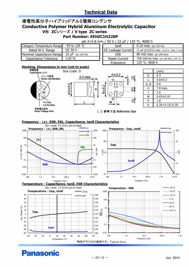
Technical Data
導電性高分子ハイブリッドアルミ電解コンデンサConductive Polymer Hybrid Aluminum Electrolytic Capacitor
V形 ZCシリーズ / V type ZC seriesPart Number: EEHZC1H220P
φ6.3×5.8 mm / 50 V / 22 μF / 125 , 4000 hCategory Temperature Range tanδ
Rated W.V. Range DC Leakage CurrentNominal Capacitance Range ESR
Capacitance Tolerance Ripple CurrentEndurance
Marking, Dimensions in mm (not to scale)Size Code: D (mm)
DL
A, BH
ZC IWPK
Frequency - |z|, ESR, ESL, Capacitance, tanδ CharacteristicsOsc. Level: 0.5 Vrms (at no load)
Temperature - Capacitance, tanδ, ESR CharacteristicsOsc. Level: 1.0 Vrms (at no load)
特性グラフは代表例です。 Typical Cirve
Jun. 2014- ZC-13 -
125 , 4000 h±20 %
-55 to 125 DC 50 V22 μF (at 120 Hz)
0.10 max. (at 120 Hz)
11 µA (0.01CV) max. (at W.V., After 2 min)
80 mΩ max. (at 100 kHz)
750 mArms max. (at 100 kHz, 125 )
1.80.35+0.15/-0.20
6.35.8±0.36.67.8 max.2.60.65±0.10
Temperature - ESR
0.01
0.1
1
10
100
1000
100 1 k 10 k 100 k 1 MFrequency (Hz)
ESR
(Ω)
-55 ºC
-45 ºC
-25 ºC
0 ºC
20 ºC
85 ºC
105 ºC
Temperature - Cap., tanδ
-50
-40
-30
-20
-10
0
10
20
30
40
50
-60 -40 -20 0 20 40 60 80 100 120
Temperature ()
Cap.
Cha
nge
(%)
0.00
0.05
0.10
0.15
0.20
0.25
0.30
0.35
0.40
0.45
0.50
tanδ
⊿Cap.
tanδ
Cap.
tan
Frequency - Cap., tanδ
0.1
1
10
100
1000
100 1 k 10 k 100 k 1 M 10 M
Frequency (Hz)
C (μ
F)
0.01
0.1
1
10
100
tanδ
Cap.
tanδ
Cap.
tanδ
Frequency - |z|, ESR, ESL
0.001
0.01
0.1
1
10
100
1000
100 1 k 10 k 100 k 1 M 10 M
Frequency (Hz)
|z|
(Ω),
ESR
(Ω
)
0.001
0.01
0.1
1
10
100
1000
ESL
(nH
)
|z|
ESR
ESL
|z|
ESR
ESL
静電容量Capacitance (μF)
シリーズ記号Series Identification
定格電圧記号Rated Voltage Mark
ロットNo.Lot Number
静電容量Capacitance (μF)
シリーズ記号Series Identification
定格電圧記号Rated Voltage Mark
ロットNo.Lot Number
K
A±0.2
( ): 参考寸法 Reference Size
(I)
B±0.
2
0.3 max.
H
L
φD
±0.
5
W
(P)
(I)
⊕
⊖
K
A±0.2
( ): 参考寸法 Reference Size
(I)
B±0.
2
0.3 max.
H
L
φD
±0.
5
W
(P)
(I)
⊕
⊖

Technical Data
導電性高分子ハイブリッドアルミ電解コンデンサConductive Polymer Hybrid Aluminum Electrolytic Capacitor
V形 ZCシリーズ / V type ZC seriesPart Number: EEHZC1H330XP
φ6.3×7.7 mm / 50 V / 33 μF / 125 , 4000 hCategory Temperature Range tanδ
Rated W.V. Range DC Leakage CurrentNominal Capacitance Range ESR
Capacitance Tolerance Ripple CurrentEndurance
Marking, Dimensions in mm (not to scale)Size Code: D8 (mm)
DL
A, BH
ZC IWPK
Frequency - |z|, ESR, ESL, Capacitance, tanδ CharacteristicsOsc. Level: 0.5 Vrms (at no load)
Temperature - Capacitance, tanδ, ESR CharacteristicsOsc. Level: 1.0 Vrms (at no load)
特性グラフは代表例です。 Typical Cirve
Jun. 2014- ZC-14 -
2.60.65±0.101.80.35+0.15/-0.20
6.37.7±0.36.67.8 max.
±20 %
-55 to 125 DC 50 V33 μF (at 120 Hz)
125 , 4000 h
0.10 max. (at 120 Hz)
16.5 µA (0.01CV) max. (at W.V., After 2 min)
40 mΩ max. (at 100 kHz)
1100 mArms max. (at 100 kHz, 125 )
Frequency - Cap., tanδ
0.1
1
10
100
1000
100 1 k 10 k 100 k 1 M 10 M
Frequency (Hz)
C (μ
F)
0.01
0.1
1
10
100
tanδ
Cap.
tanδ
Cap.
tanδ
Temperature - ESR
0.01
0.1
1
10
100
1000
100 1 k 10 k 100 k 1 MFrequency (Hz)
ESR
(Ω)
-55 ºC
-40 ºC
-25 ºC
0 ºC
20 ºC
85 ºC
105 ºC
125 ºC
Frequency - |z|, ESR, ESL
0.001
0.01
0.1
1
10
100
1000
100 1 k 10 k 100 k 1 M 10 M
Frequency (Hz)
|z|
(Ω),
ESR
(Ω
)
0.001
0.01
0.1
1
10
100
1000
ESL
(nH
)
|z|
ESR
ESL
|z|
ESR
ESL
Temperature - Cap., tanδ
-50
-40
-30
-20
-10
0
10
20
30
40
50
-60 -40 -20 0 20 40 60 80 100 120 140
Temperature ()
Cap.
Cha
nge
(%)
0.00
0.05
0.10
0.15
0.20
0.25
0.30
0.35
0.40
0.45
0.50
tanδ
⊿Cap.
tanδ
Cap.
tan
静電容量Capacitance (μF)
シリーズ記号Series Identification
定格電圧記号Rated Voltage Mark
ロットNo.Lot Number
静電容量Capacitance (μF)
シリーズ記号Series Identification
定格電圧記号Rated Voltage Mark
ロットNo.Lot Number
K
A±0.2
( ): 参考寸法 Reference Size
(I)
B±0.
2
0.3 max.
H
L
φD
±0.
5
W
(P)
(I)
⊕
⊖
K
A±0.2
( ): 参考寸法 Reference Size
(I)
B±0.
2
0.3 max.
H
L
φD
±0.
5
W
(P)
(I)
⊕
⊖

Technical Data
導電性高分子ハイブリッドアルミ電解コンデンサConductive Polymer Hybrid Aluminum Electrolytic Capacitor
V形 ZCシリーズ / V type ZC seriesPart Number: EEHZC1H680P
φ8.0×10.2 mm / 50 V / 68 μF / 125 , 4000 hCategory Temperature Range tanδ
Rated W.V. Range DC Leakage CurrentNominal Capacitance Range ESR
Capacitance Tolerance Ripple CurrentEndurance
Marking, Dimensions in mm (not to scale)Size Code: F (mm)
DL
A, BH
ZC IWPK
Frequency - |z|, ESR, ESL, Capacitance, tanδ CharacteristicsOsc. Level: 0.5 Vrms (at no load)
Temperature - Capacitance, tanδ, ESR CharacteristicsOsc. Level: 1.0 Vrms (at no load)
特性グラフは代表例です。 Typical Cirve
Jun. 2014- ZC-15 -
125 , 4000 h±20 %
-55 to 125 DC 50 V68 μF (at 120 Hz)
0.1 max. (at 120 Hz)
34 µA (0.01CV) max. (at W.V., After 2 min)
30 mΩ max. (at 100 kHz)
1250 mArms max. (at 100 kHz, 125 )
3.10.7±0.2
8.010.2±0.38.310.0 max.3.40.9±0.2
Frequency - |z|, ESR, ESL
0.001
0.01
0.1
1
10
100
1000
100 1 k 10 k 100 k 1 M 10 M
Frequency (Hz)
|z|
(Ω),
ESR
(Ω)
0.001
0.01
0.1
1
10
100
1000
ESL
(nH)
|z|
ESR
ESL
|z|
ESR
ESL
Frequency - Cap., tanδ
0.1
1
10
100
1000
100 1 k 10 k 100 k 1 M 10 M
Frequency (Hz)
C (μ
F)
0.01
0.1
1
10
100
tanδ
Cap.
tanδ
Cap.
tanδ
Temperature - Cap., tanδ
-50
-40
-30
-20
-10
0
10
20
30
40
50
-60 -40 -20 0 20 40 60 80 100 120 140
Temperature ()
Cap.
Cha
nge
(%)
0.00
0.05
0.10
0.15
0.20
0.25
0.30
0.35
0.40
0.45
0.50
tanδ
⊿Cap.
tanδ
Temperature - ESR
0.01
0.1
1
10
100
1000
100 1 k 10 k 100 k 1 MFrequency (Hz)
ESR
(Ω)
-55 ºC
-40 ºC
-25 ºC
0 ºC
20 ºC
85 ºC
105 ºC
125 ºC
静電容量Capacitance (μF)
シリーズ記号Series Identification
定格電圧記号Rated Voltage Mark
ロットNo.Lot Number
静電容量Capacitance (μF)
シリーズ記号Series Identification
定格電圧記号Rated Voltage Mark
ロットNo.Lot Number
K
A±0.2
( ): 参考寸法 Reference Size
(I)
B±0.
2
0.3 max.
H
L
φD
±0.
5
W
(P)
(I)
⊕
⊖
K
A±0.2
( ): 参考寸法 Reference Size
(I)
B±0.
2
0.3 max.
H
L
φD
±0.
5
W
(P)
(I)
⊕
⊖

Technical Data
導電性高分子ハイブリッドアルミ電解コンデンサConductive Polymer Hybrid Aluminum Electrolytic Capacitor
V形 ZCシリーズ / V type ZC seriesPart Number: EEHZC1H101P
φ10.0×10.2 mm / 50 V / 100 μF / 125 , 4000 hCategory Temperature Range tanδ
Rated W.V. Range DC Leakage CurrentNominal Capacitance Range ESR
Capacitance Tolerance Ripple CurrentEndurance
Marking, Dimensions in mm (not to scale)Size Code: G (mm)
DL
A, BH
ZC IWPK
Frequency - |z|, ESR, ESL, Capacitance, tanδ CharacteristicsOsc. Level: 0.5 Vrms (at no load)
Temperature - Capacitance, tanδ, ESR CharacteristicsOsc. Level: 1.0 Vrms (at no load)
特性グラフは代表例です。 Typical Cirve
Jun. 2014- ZC-16 -
3.50.9±0.24.60.7±0.2
10.010.2±0.310.312.0 max.
±20 %
-55 to 125 DC 50 V100 μF (at 120 Hz)
125 , 4000 h
0.1 max. (at 120 Hz)
50 µA (0.01CV) max. (at W.V., After 2 min)
28 mΩ max. (at 100 kHz)
1600 mArms max. (at 100 kHz, 105 )
Frequency - Cap., tanδ
0.1
1
10
100
1000
100 1 k 10 k 100 k 1 M 10 M
Frequency (Hz)
C (μ
F)
0.01
0.1
1
10
100
tanδ
Cap.
tanδ
Cap.
tanδ
Temperature - ESR
0.01
0.1
1
10
100
1000
100 1 k 10 k 100 k 1 MFrequency (Hz)
ESR
(Ω)
-55 ºC
-40 ºC
-25 ºC
0 ºC
20 ºC
85 ºC
105 ºC
125 ºC
Temperature - Cap., tanδ
-50
-40
-30
-20
-10
0
10
20
30
40
50
-60 -40 -20 0 20 40 60 80 100 120 140
Temperature ()
Cap.
Cha
nge
(%)
0.00
0.05
0.10
0.15
0.20
0.25
0.30
0.35
0.40
0.45
0.50
tanδ
⊿Cap.
tanδ
Frequency - |z|, ESR, ESL
0.001
0.01
0.1
1
10
100
1000
100 1 k 10 k 100 k 1 M 10 M
Frequency (Hz)
|z|
(Ω),
ESR
(Ω
)
0.001
0.01
0.1
1
10
100
1000
ESL
(nH
)
|z|
ESR
ESL
|z|
ESR
ESL
静電容量Capacitance (μF)
シリーズ記号Series Identification
定格電圧記号Rated Voltage Mark
ロットNo.Lot Number
静電容量Capacitance (μF)
シリーズ記号Series Identification
定格電圧記号Rated Voltage Mark
ロットNo.Lot Number
K
A±0.2
( ): 参考寸法 Reference Size
(I)
B±0.
2
0.3 max.
H
L
φD
±0.
5
W
(P)
(I)
⊕
⊖
K
A±0.2
( ): 参考寸法 Reference Size
(I)
B±0.
2
0.3 max.
H
L
φD
±0.
5
W
(P)
(I)
⊕
⊖
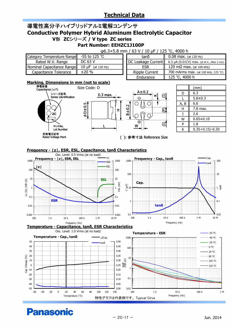
Technical Data
導電性高分子ハイブリッドアルミ電解コンデンサConductive Polymer Hybrid Aluminum Electrolytic Capacitor
V形 ZCシリーズ / V type ZC seriesPart Number: EEHZC1J100P
φ6.3×5.8 mm / 63 V / 10 μF / 125 , 4000 hCategory Temperature Range tanδ
Rated W.V. Range DC Leakage CurrentNominal Capacitance Range ESR
Capacitance Tolerance Ripple CurrentEndurance
Marking, Dimensions in mm (not to scale)Size Code: D (mm)
DL
A, BH
ZC IWPK
Frequency - |z|, ESR, ESL, Capacitance, tanδ CharacteristicsOsc. Level: 0.5 Vrms (at no load)
Temperature - Capacitance, tanδ, ESR CharacteristicsOsc. Level: 1.0 Vrms (at no load)
特性グラフは代表例です。 Typical Cirve
Jun. 2014- ZC-17 -
2.60.65±0.101.80.35+0.15/-0.20
6.35.8±0.36.67.8 max.
±20 %
-55 to 125 DC 63 V10 μF (at 120 Hz)
125 , 4000 h
0.08 max. (at 120 Hz)
6.3 µA (0.01CV) max. (at W.V., After 2 min)
120 mΩ max. (at 100 kHz)
700 mArms max. (at 100 kHz, 125 )
Frequency - Cap., tanδ
0.1
1
10
100
1000
100 1 k 10 k 100 k 1 M 10 M
Frequency (Hz)
C (μ
F)
0.01
0.1
1
10
100
tanδ
Cap.
tanδ
Cap.
tanδ
Temperature - Cap., tanδ
-50
-40
-30
-20
-10
0
10
20
30
40
50
-60 -40 -20 0 20 40 60 80 100 120 140
Temperature ()
Cap.
Cha
nge
(%)
0.00
0.05
0.10
0.15
0.20
0.25
0.30
0.35
0.40
0.45
0.50
tanδ
⊿Cap.
tanδ
Temperature - ESR
0.01
0.1
1
10
100
1000
100 1 k 10 k 100 k 1 MFrequency (Hz)
ESR
(Ω)
-55 ºC
-40 ºC
-25 ºC
0 ºC
20 ºC
85 ºC
105 ºC
125 ºC
Frequency - |z|, ESR, ESL
0.001
0.01
0.1
1
10
100
1000
100 1 k 10 k 100 k 1 M 10 M
Frequency (Hz)
|z|
(Ω),
ESR
(Ω
)
0.001
0.01
0.1
1
10
100
1000
ESL
(nH
)
|z|
ESR
ESL|z|
ESR
ESL
静電容量Capacitance (μF)
シリーズ記号Series Identification
定格電圧記号Rated Voltage Mark
ロットNo.Lot Number
静電容量Capacitance (μF)
シリーズ記号Series Identification
定格電圧記号Rated Voltage Mark
ロットNo.Lot Number
K
A±0.2
( ): 参考寸法 Reference Size
(I)
B±0.
2
0.3 max.
H
L
φD
±0.
5
W
(P)
(I)
⊕
⊖
K
A±0.2
( ): 参考寸法 Reference Size
(I)
B±0.
2
0.3 max.
H
L
φD
±0.
5
W
(P)
(I)
⊕
⊖

Technical Data
導電性高分子ハイブリッドアルミ電解コンデンサConductive Polymer Hybrid Aluminum Electrolytic Capacitor
V形 ZCシリーズ / V type ZC seriesPart Number: EEHZC1J220XP
φ6.3×7.7 mm / 63 V / 22 μF / 125 , 4000 hCategory Temperature Range tanδ
Rated W.V. Range DC Leakage CurrentNominal Capacitance Range ESR
Capacitance Tolerance Ripple CurrentEndurance
Marking, Dimensions in mm (not to scale)Size Code: D8 (mm)
DL
A, BH
ZC IWPK
Frequency - |z|, ESR, ESL, Capacitance, tanδ CharacteristicsOsc. Level: 0.5 Vrms (at no load)
Temperature - Capacitance, tanδ, ESR CharacteristicsOsc. Level: 1.0 Vrms (at no load)
特性グラフは代表例です。 Typical Cirve
Jun. 2014- ZC-18 -
2.60.65±0.101.80.35+0.15/-0.20
6.37.7±0.36.67.8 max.
±20 %
-55 to 125 DC 63 V22 μF (at 120 Hz)
125 , 4000 h
0.08 max. (at 120 Hz)
13.8 µA (0.01CV) max. (at W.V., After 2 min)
80 mΩ max. (at 100 kHz)
900 mArms max. (at 100 kHz, 125 )
Temperature - Cap., tanδ
-50
-40
-30
-20
-10
0
10
20
30
40
50
-60 -40 -20 0 20 40 60 80 100 120 140
Temperature ()
Cap.
Cha
nge
(%)
0.00
0.05
0.10
0.15
0.20
0.25
0.30
0.35
0.40
0.45
0.50
tanδ
⊿Cap.
tanδ
Temperature - ESR
0.01
0.1
1
10
100
1000
100 1 k 10 k 100 k 1 MFrequency (Hz)
ESR
(Ω)
-55 ºC
-40 ºC
-25 ºC
0 ºC
20 ºC
85 ºC
105 ºC
125 ºC
Frequency - |z|, ESR, ESL
0.001
0.01
0.1
1
10
100
1000
100 1 k 10 k 100 k 1 M 10 M
Frequency (Hz)
|z|
(Ω),
ESR
(Ω)
0.001
0.01
0.1
1
10
100
1000
ESL
(nH)
|z|
ESR
ESL
|z|
ESR
ESL
Frequency - Cap., tanδ
0.1
1
10
100
1000
100 1 k 10 k 100 k 1 M 10 M
Frequency (Hz)
C (μ
F)
0.01
0.1
1
10
100
tanδ
Cap.
tanδ
Cap.
tanδ
静電容量Capacitance (μF)
シリーズ記号Series Identification
定格電圧記号Rated Voltage Mark
ロットNo.Lot Number
静電容量Capacitance (μF)
シリーズ記号Series Identification
定格電圧記号Rated Voltage Mark
ロットNo.Lot Number
K
A±0.2
( ): 参考寸法 Reference Size
(I)
B±0.
2
0.3 max.
H
L
φD
±0.
5
W
(P)
(I)
⊕
⊖
K
A±0.2
( ): 参考寸法 Reference Size
(I)
B±0.
2
0.3 max.
H
L
φD
±0.
5
W
(P)
(I)
⊕
⊖

Technical Data
導電性高分子ハイブリッドアルミ電解コンデンサConductive Polymer Hybrid Aluminum Electrolytic Capacitor
V形 ZCシリーズ / V type ZC seriesPart Number: EEHZC1J330P
φ8.0×10.2 mm / 63 V / 33 μF / 125 , 4000 hCategory Temperature Range tanδ
Rated W.V. Range DC Leakage CurrentNominal Capacitance Range ESR
Capacitance Tolerance Ripple CurrentEndurance
Marking, Dimensions in mm (not to scale)Size Code: F (mm)
DL
A, BH
ZC IWPK
Frequency - |z|, ESR, ESL, Capacitance, tanδ CharacteristicsOsc. Level: 0.5 Vrms (at no load)
Temperature - Capacitance, tanδ, ESR CharacteristicsOsc. Level: 1.0 Vrms (at no load)
特性グラフは代表例です。 Typical Cirve
Jun. 2014- ZC-19 -
125 , 4000 h
0.08 max. (at 120 Hz)
20.7 µA (0.01CV) max. (at W.V., After 2 min)
40 mΩ max. (at 100 kHz)
1100 mArms max. (at 100 kHz, 125 )±20 %
-55 to 125 DC 63 V33 μF (at 120 Hz)
3.10.7±0.2
8.010.2±0.38.310.0 max.3.40.9±0.2
Frequency - Cap., tanδ
0.1
1
10
100
1000
100 1 k 10 k 100 k 1 M 10 M
Frequency (Hz)
C (μ
F)
0.01
0.1
1
10
100
tanδ
Cap.
tanδ
Cap.
tanδ
Temperature - Cap., tanδ
-50
-40
-30
-20
-10
0
10
20
30
40
50
-60 -40 -20 0 20 40 60 80 100 120 140
Temperature ()
Cap.
Cha
nge
(%)
0.00
0.05
0.10
0.15
0.20
0.25
0.30
0.35
0.40
0.45
0.50
tanδ
⊿Cap.
tanδ
Temperature - ESR
0.01
0.1
1
10
100
1000
100 1 k 10 k 100 k 1 MFrequency (Hz)
ESR
(Ω)
-55 ºC
-40 ºC
-25 ºC
0 ºC
20 ºC
85 ºC
105 ºC
125 ºC
Frequency - |z|, ESR, ESL
0.001
0.01
0.1
1
10
100
1000
100 1 k 10 k 100 k 1 M 10 M
Frequency (Hz)
|z|
(Ω),
ESR
(Ω
)
0.001
0.01
0.1
1
10
100
1000
ESL
(nH
)
|z|
ESR
ESL
|z|
ESR
ESL
静電容量Capacitance (μF)
シリーズ記号Series Identification
定格電圧記号Rated Voltage Mark
ロットNo.Lot Number
静電容量Capacitance (μF)
シリーズ記号Series Identification
定格電圧記号Rated Voltage Mark
ロットNo.Lot Number
K
A±0.2
( ): 参考寸法 Reference Size
(I)
B±0.
2
0.3 max.
H
L
φD
±0.
5
W
(P)
(I)
⊕
⊖
K
A±0.2
( ): 参考寸法 Reference Size
(I)
B±0.
2
0.3 max.
H
L
φD
±0.
5
W
(P)
(I)
⊕
⊖

Technical Data
導電性高分子ハイブリッドアルミ電解コンデンサConductive Polymer Hybrid Aluminum Electrolytic Capacitor
V形 ZCシリーズ / V type ZC seriesPart Number: EEHZC1J560P
φ10.0×10.2 mm / 63 V / 56 μF / 125 , 4000 hCategory Temperature Range tanδ
Rated W.V. Range DC Leakage CurrentNominal Capacitance Range ESR
Capacitance Tolerance Ripple CurrentEndurance
Marking, Dimensions in mm (not to scale)Size Code: G (mm)
DL
A, BH
ZC IWPK
Frequency - |z|, ESR, ESL, Capacitance, tanδ CharacteristicsOsc. Level: 0.5 Vrms (at no load)
Temperature - Capacitance, tanδ, ESR CharacteristicsOsc. Level: 1.0 Vrms (at no load)
特性グラフは代表例です。 Typical Cirve
Jun. 2014- ZC-20 -
3.50.9±0.24.60.7±0.2
10.010.2±0.310.312.0 max.
±20 %
-55 to 125 DC 63 V56 μF (at 120 Hz)
125 , 4000 h
0.08 max. (at 120 Hz)
35.2 µA (0.01CV) max. (at W.V., After 2 min)
30 mΩ max. (at 100 kHz)
1400 mArms max. (at 100 kHz, 125 )
Frequency - Cap., tanδ
0.1
1
10
100
1000
100 1 k 10 k 100 k 1 M 10 M
Frequency (Hz)
C (μ
F)
0.01
0.1
1
10
100
tanδ
Cap.
tanδ
Cap.
tanδ
Temperature - Cap., tanδ
-50
-40
-30
-20
-10
0
10
20
30
40
50
-60 -40 -20 0 20 40 60 80 100 120 140
Temperature ()
Cap.
Cha
nge
(%)
0.00
0.05
0.10
0.15
0.20
0.25
0.30
0.35
0.40
0.45
0.50
tanδ
⊿Cap.
tanδ
Temperature - ESR
0.01
0.1
1
10
100
1000
100 1 k 10 k 100 k 1 MFrequency (Hz)
ESR
(Ω)
-55 ºC
-40 ºC
-25 ºC
0 ºC
20 ºC
85 ºC
105 ºC
125 ºC
Frequency - |z|, ESR, ESL
0.001
0.01
0.1
1
10
100
1000
100 1 k 10 k 100 k 1 M 10 M
Frequency (Hz)
|z|
(Ω),
ESR
(Ω
)
0.001
0.01
0.1
1
10
100
1000
ESL
(nH
)
|z|
ESR
ESL
|z|
ESR
ESL
静電容量Capacitance (μF)
シリーズ記号Series Identification
定格電圧記号Rated Voltage Mark
ロットNo.Lot Number
静電容量Capacitance (μF)
シリーズ記号Series Identification
定格電圧記号Rated Voltage Mark
ロットNo.Lot Number
K
A±0.2
( ): 参考寸法 Reference Size
(I)
B±0.
2
0.3 max.
H
L
φD
±0.
5
W
(P)
(I)
⊕
⊖
K
A±0.2
( ): 参考寸法 Reference Size
(I)
B±0.
2
0.3 max.
H
L
φD
±0.
5
W
(P)
(I)
⊕
⊖
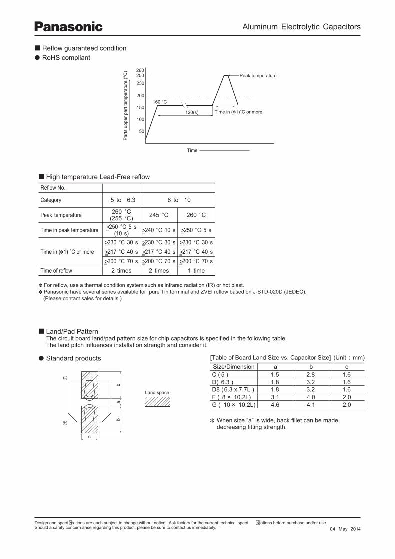
Aluminum Electrolytic Capacitors
Design and speci cations are each subject to change without notice. Ask factory for the current technical speci cations before purchase and/or use.Should a safety concern arise regarding this product, please be sure to contact us immediately.
230
200
150
100
50
Time
Par
ts u
pper
par
t tem
pera
ture
(°C
)
160 °C
120(s) Time in ( 1)°C or more
Peak temperature250260
Refl ow No.
Category 5 to 6.3 8 to 10
Peak temperature 260 °C(255 °C) 245 °C 260 °C
Time in peak temperature >250 °C 5 s(10 s) >240 °C 10 s >250 °C 5 s
Time in ( 1) °C or more>230 °C 30 s >230 °C 30 s >230 °C 30 s>217 °C 40 s >217 °C 40 s >217 °C 40 s>200 °C 70 s >200 °C 70 s >200 °C 70 s
Time of refl ow 2 times 2 times 1 time
RoHS compliant
For refl ow, use a thermal condition system such as infrared radiation (IR) or hot blast. Panasonic have several series available for pure Tin terminal and ZVEI refl ow based on J-STD-020D (JEDEC).
(Please contact sales for details.)
04 May. 2014
===
=
=
=
=
=
=
=
=
=
ab
b
c
Land space
+
–
Land/Pad PatternThe circuit board land/pad pattern size for chip capacitors is specifi ed in the following table.The land pitch infl uences installation strength and consider it.
[Table of Board Land Size vs. Capacitor Size]Size/Dimension a b cC ( 5 ) 1.5 2.8 1.6D( 6.3 ) 1.8 3.2 1.6
F ( 8 × 10.2L) 3.1 4.0 2.0G ( 10 × 10.2L) 4.6 4.1 2.0
(Unit : mm) Standard products
When size “a” is wide, back fi llet can be made, decreasing fi tting strength.
6.3 x 7.7L ) D8 ( 1.8 3.2 1.6
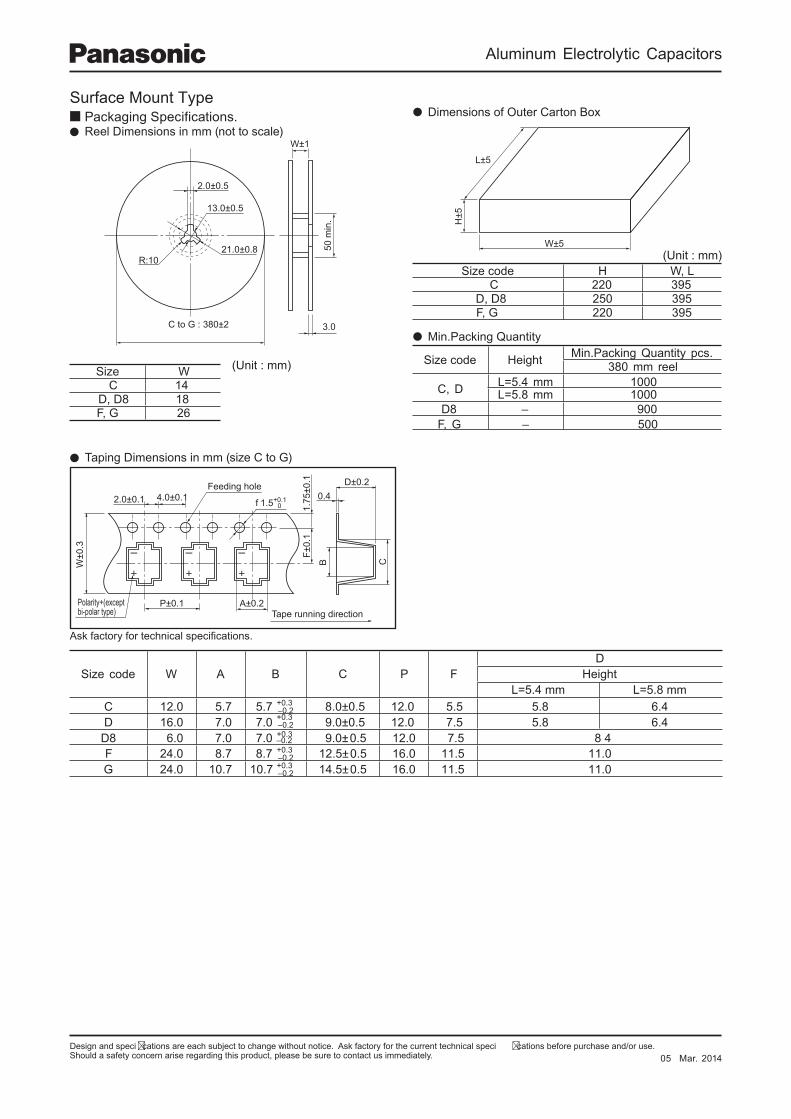
Design and speci cations are each subject to change without notice. Ask factory for the current technical speci cations before purchase and/or use.Should a safety concern arise regarding this product, please be sure to contact us immediately.
Aluminum Electrolytic Capacitors
W±0
.3
F±0.
11.
75±0
.1
A±0.2
B
P±0.1
2.0±0.1 4.0±0.1 0.4D±0.2
C
f 1.5+0.10
Tape running direction
Feeding hole
Polarity+(exceptbi-polar type)
W±5
H±5
L±5
W±1
50 m
in.
2.0±0.5
13.0±0.5
21.0±0.8R:10
3.0 C to G : 380±2
Packaging Spec i ca tions. Reel Dimensions in mm (not to scale)
Surface Mount Type
Ask factory for technical specifi cations.
Size code W A B C P FD
HeightL=5.4 mm L=5.8 mm
C 12.0 5.7 5.7 8.0±0.5 12.0 5.5 5.8 6.4D 16.0 7.0 7.0 9.0±0.5 12.0 7.5 5.8 6.4
48 5.7 0.215.0±0.9 0.7 0.7 0.68D0.115.110.615.0±5.217.8 7.8 0.42F0.115.110.615.0±5.417.017.010.42G
+0.3–0.2+0.3–0.2+0.3
+0.3–0.2+0.3–0.2
Taping Dimensions in mm (size C to G)
(Unit : mm)Size W C 14
D, D8 18F, G 26
Size code Height Min.Packing Quantity pcs.380 mm reel
C, D L=5.4 mm 1000L=5.8 mm 1000
D8 – 900F, G – 500
Min.Packing Quantity
Size code H W, L C 220 395
D, D8 250 395F, G 220 395
(Unit : mm)
Dimensions of Outer Carton Box
05 Mar. 2014
–0.2
Aluminum Electrolytic Capacitors
Design and specifi cations are each subject to change without notice. Ask factory for the current technical specifi cations before purchase and/or use.Should a safety concern arise regarding this product, please be sure to contact us immediately.
Notices Applicable laws and regulations
This product satisfies the requirements of the RoHS Directive (2011/65/EU) (related to the specified hazardous
substances contained in electrical and electronic equipment).
The ozone-depleting chemicals regulated by the Montreal Protocol are not intentionally used in the materials used in
our manufacturing processes.
PBBs(Poly-Brominated Biphenyls)/PBDEs (Poly-Brominated Diphenyl ethers)
The above specifi ed brominated fl ame retardants are not intentionally used.
The materials used in this product are all referred to as existing chemicals by the Law Concerning Examination and
Regulation of Manufacture and Handling of Chemical Substances.
When exporting this product, observe the export procedures specifi ed in export control laws such as the Foreign
Exchange and Foreign Trade Control Law.
Limited applications This product is intended to be used for general-purpose standard applications for general electronic equipment
(such as AV equipment, household appliances, business or office equipment, information or communications
equipment, etc.)
If this product is being examined for possible use in applications where higher reliability or safety is required, in
cases where a malfunction of this product may endanger life or property, then the delivery specifi cations meeting
the application requirements must be agreed to and exchanged.
Items to be observed
(1) The purpose of these specifi cations is to ensure the quality of components as individual components.
Before use, check and evaluate their operation when mounted on your products.
(2) Do not use our components outside of the corresponding specifi cations.
When using this capacitor in a prod uct where safety is crit i cal
We take great care in the quality of this product. However, performance may deteriorate and short-circuiting
or open-circuiting may occur if it will be used in transportation equipment (e.g. trains, cars, traffi c lights),
medical equipment, airborne equipment, aerospace equipment, electric heating appliances, combustion/
gas equipment, rotating equipment, disaster/crime prevention equipment, or other equipment where a
defect in this component may cause the loss of human life or other signifi cant damage. Ensure that the
target equipment has a failsafe design and is provided with the following systems to guarantee adequate
safety.
(1) * Ensure the safety of the whole system by installing a protection circuit and a protection device.
(2) Redundant circuits, etc. to maintain the safety of the entire system so that a single independent failure
will not lead to unsafe conditions.
Conditions of use
This product is intended to be used in electronic equipment for general-purpose standard applications and is
not designed for use in any special environments.
When this capacitor is used in a special environment or under special conditions, its performance may be
affected. Before use, verify the performance and reliability of the capacitor.
03 May. 2014
Aluminum Electrolytic Capacitors
Design and specifi cations are each subject to change without notice. Ask factory for the current technical specifi cations before purchase and/or use.Should a safety concern arise regarding this product, please be sure to contact us immediately.
Application Guidelines
1. Circuit design
Verify the usage and fitting environments and make sure to observe the rated performance specified in thecorresponding catalog or specifi cations.
1.1 Operating temperature and frequency
Variations in temperature and frequency can affect the electrical characteristics of capacitors. Design circuits allowing for these variations.
(1) At high temperatures leakage current increases. (2) At low temperatures the capacitance decreases and an increase in the tangent of the loss angle and impedance.(3) As frequency increases, capacitance decreases and the tangent of the loss angle increases, while the capacitive portion of impedance decreases till the resonant frequency is reached.(4) At low frequency there is temperature rise caused by ripple currents accompanying the increase in equivalent series resistance.
1.2 Operating temperature and life expectancy
(1) The capacitor life is affected by usage temperature. In general, the capacitor life is approximately doubled when the temperature decreases by 10 °C. Reduce the usage temperature as much as possible.
(2) The use of capacitors beyond the upper category temperatures may cause rapid deterioration in the characteristics and break down may occur. The temperature referred to here includes the ambient temperature(within equipment), including heat produced by heat generating devices (power transistors, resistors, etc.), self-heating due to ripple currents, etc. Take these factors into consideration when checking the temperature of capacitors. Do not place any heat generating devices, etc. on the back of capacitors.
(3) The life acceleration can be calculated with the following equation:T1–T2
10L2 = L1×2
L1 : Life at a temperature T1 °C (h)L2 : Life at a temperature T2 °C (h)T1 : Category upper limit temperature + heat generation due to ripple currents (°C)T2 : Ambient temperature to calculate the life + heat generation due to ripple currents (°C)
1.3 Common application conditions to avoid
If the loads shown below are applied to a capacitor, then its characteristics may degrade rapidly or it may short-circuit. Rapid heat or gas generation may occur, which leads to the activation of the pressure valve. Electrolytes will then leak from the sealing section. In the worst case, an explosion or ignition may occur.When the capacitor breaks down, combustible materials (electrolytes, element fi xing materials, etc.) may fl ow externally in all directions.
(1) PolarityAluminum electrolytic capacitors have polarities.Do not apply a reversed or alternating-current voltage.If the polarity is reversed, then short-circuiting may occur in the initial state or the pressure valve may be activated, leading to capacitor breakdown.Check the polarity when using a polar capacitor.If the polarity is unstable or unclear in a circuit, then use bipolar capacitors. However, bipolar capacitors cannot be used in alternating current circuits.
(2) Applied voltageDo not apply an excessive voltage (voltage exceeding the rating).The peak direct current voltage superposed with a ripple voltage (alternating current component) must be equal to or less than the rated voltage. A surge voltage exceeding the rated voltage is allowed and specifi ed. However, the allowable conditions are limited and the specifi cations do not guarantee the application of such a surge voltage for a long time.
(3) Ripple currentDo not allow an excessive current (current exceeding the rated ripple current) to pass.If an excessive ripple current passes through, then the amount of internally generated heat will grow, the capacitor life will be reduced, or the pressure valve will be activated, leading to breakdown.Even if the current is equivalent to or less than the allowable level, a reversed voltage may be applied when a direct current bias voltage is low. Use capacitors so that a reversed voltage is not applied.
03 May. 2014
Aluminum Electrolytic Capacitors
Design and specifi cations are each subject to change without notice. Ask factory for the current technical specifi cations before purchase and/or use.Should a safety concern arise regarding this product, please be sure to contact us immediately.
(4) Charging/discharging applicationsStandard capacitors are not suitable for use in repeating charge/discharge applications. For charge/discharge applications, consult us with your actual application condition.For rush current, please to nor exceed 100 A.
(5) ON-OFF circuitDo not use capacitors in circuit where ON-OFF switching is repeated more than 10000 times/per day.In case of applying to the theses ON-OFF circuit, consult with us about circuit condition and so on.
(6) Series/parallel connection[Parallel connection]If capacitors are connected in parallel, then the balance of currents between these capacitors may be disrupted and an excessive ripple current may pass through only part of these capacitors.Wire your circuits such that excessive ripple current does not pass through the capacitors.
[Series connection]If capacitors are connected in series, then the balance of voltages between these capacitors may be disrupted and excessive voltage may be applied. Add a bleeder resistor in parallel with each capacitor. By taking leak currents into consideration the balance of voltages will not be disrupted.
(7) Electrical isolation of the capacitorsIsolate capacitors completely in a circuit in the following cases.Between the housing and cathode and anode terminals and between circuit traces.
(8) Capacitor sleeveExterior sleeves or lamination covering capacitors are for indication purposes only and do not guarantee electrical insulation.
1.4 Capacitor mounting considerations
For aluminum electrolytic capacitors, conductive electrolysis whose main solvent is combustible organic solvent and combustible electrolytic paper is used.If the electrolysis leaks onto a printed circuit board, then it may corrode or short-circuit the traces, leading to smoke or fi re. Check the following points when designing products.
(1) Double-sided circuit boardIf capacitors are used in double-sided boards, then do not lay wiring traces immediately below the capacitors.If the sealed part of a capacitor adheres to the surface of a through-hole printed circuit board, then the solder may be absorbed into the gap during dip soldering and the anode and cathode terminals may be short-circuited.
(2) Circuit board hole positioningSolder may protrude from the through-holes or holes for post-mounted component leads and damage the capacitor exterior sleeves. Be mindful of the hole positions.
(3) Circuit board hole spacingMake holes for capacitors with a gap equivalent to that of capacitor leads (terminals) during design. Otherwise, there will be stress on the capacitor leads when they are inserted into these holes, leading to current leaks,short-circuiting, or electrolysis leakage.
(4) Surface-mount typesFor surface-mount type capacitors, design land traces with reference to the recommended board land sizesdescribed in the delivery specifi cations, etc.
(5) Capacitors equipped with pressure valvesProvide a space above the pressure valve so that it can operate properly.For capacitors equipped with a pressure valve (as per the shape and dimensional descriptions of each series),provide a space as follows. If the space is smaller than the requirements, then the pressure valve may not operate properly, leading to an explosion.
Product diameter Space 06.3 to 016 mm 2 mm or more 018 to 035 mm 3 mm or more 040 mm or more 5 mm or more
(6) Clearance for seal mounted pressure relief ventsWhen the pressure valve section of a capacitor faces the printed wiring, provide a degassing hole aligned with the pressure valve position for proper operation of the valve.
(7) Wiring near the pressure relief vent.Considerations must be taken in designing circuits so that there are no traces, particularly for high-voltage or large-current wiring, above the pressure valve sections. When a pressure valve is activated, combustible high-temperature gas exceeding 100°C will be released. Gas may condense or the wiring covers may melt and secondary accidents may occur.
(8) Circuit board patterns under the capacitor.If electrolysis leaks, then the circuit traces may short-circuit and tracking or migration may occur.
03 May. 2014
Aluminum Electrolytic Capacitors
Design and specifi cations are each subject to change without notice. Ask factory for the current technical specifi cations before purchase and/or use.Should a safety concern arise regarding this product, please be sure to contact us immediately.
2. Mounting
2.1 Considerations before using
(1) Do not reuse capacitors that have been installed and energized.(2) Capacitors may generate transient recovery voltages. In this case, discharge them using a resistor of approx. 1 kΩ.(3) Capacitors stored for a long time may have a larger current leak.
In this case, dispose the voltage using a resistor of approx. 1 kΩ.(4) Do not drop capacitors onto a fl oor, etc.
Do not use dropped capacitors because they may be damaged mechanically or electrically.(5) Do not use corrupted capacitors.
If a capacitor s seal is deteriorated, then its performance will be degraded, life reduced, and/or the electrolytewill leak.
2.2 Capacitor insertion
(1) Check the capacitor ratings (capacitance and voltage) before mounting.(2) Check the capacitor polarity before mounting.(3) Check the capacitor lead and hole intervals and land size before mounting.
If these intervals are different, then stress will be applied to the inside of the capacitor through its leads when theyare inserted into the board holes, leading to short-circuiting or other failures.
(4) When an automatic mounter is used, the force to clinch and fi x capacitor leads must not be excessive.When capacitor leads are clinched and fi xed onto a circuit board, the leads may be pulled and a large force applied to the capacitor if there are missing cogs or the gap between the clinching section and the circuit board is too small. If this is the case, then the capacitor may break down.For surface-mount type capacitors, if the mounting pressure is excessive, then current leaks may increase,short-circuiting may occur, or the capacitor may break down and come off.
2.3 Manual soldering
(1) Solder capacitors under the soldering conditions (temperature and time) as described in the specifi cations or at350 °C for three seconds or less.
(2) If the capacitor lead terminals must be pre-processed in order to align the gaps between the terminals and holes, place them before soldering to prevent stress from being applied to the capacitor body.
(3) If it is necessary to manually remove soldered capacitors, repair them after the solder has suffi ciently melted toprevent stress from being applied to the capacitor terminals.
(4) Do not touch the capacitor body with the soldering iron tip. Otherwise, a hole may occur on the capacitor exterior sleeve. The sleeve may break or become damaged.
2.4 Flow soldering
(1) Do not immerse the capacitor body in a solder bath. The capacitor’s inner pressure could increase and the capacitorwill break down.
(2) Solder capacitors under the soldering conditions (temperature and time) described in the specifi cations.(3) When soldering, do not allow other components to fall or touch the capacitors.
When soldering, if resistors, ceramic capacitors, or other components (with a high heat conductance) fall and their lead terminals or metallic sections touch the capacitor, then local thermal stress can occur causing the capacitor’s exterior sleeve to break down. This phenomenon is identical to short-circuiting.
(4) Prevent fl ux from adhering to anything other than the terminals.
2.5 Refl ow soldering for chip capacitors
(1) Surface-mount type capacitor are exclusively for refl ow soldering. When refl ow solder is used an ambient heat condition system such as the simultaneous use of infrared and hot-air is recommended. This system cannot be used for fl ow or dip soldering.
(2) Soldering capacitors under the soldering conditions (pre-heating, soldering temperature and time) described in thespecifi cations.
(3) Refl ow-solder only once.If you need to apply refl ow soldering twice, then make sure to contact us.
(4) Do not reuse the installed surface-mount type capacitors.(5) The crack on top marking might be occurred by refl ow heat stress.
But please acknowledge that it does not infl uence the reliability of the product.(6) VPS (Vapor Phase Soldering) refl ow can cause signifi cant characteristics change and/ or mounting failure due to
deformation by acute temperature rise. VPS is acceptable provided that the process does not exceed recommended refl ow profi le and temperature rise is less than 3degC/sec. Please contact Panasonic for detailed conditions.
2.6 Other soldering considerations
If the chip capacitor temperature becomes very high due to pre-heating or hardening of the fi xing resin, then thecapacitor exterior sleeve may shrink or crack. If capacitors are passed through a heat-curing furnace, then the ambient temperature must be 150°C or less and the duration must be two minutes or less.
2.7 Capacitor handling after soldering
(1) Do not tilt, bring down, or twist the capacitors soldered to the printed circuit board; otherwise a torque will be generatedwith the capacitor circumference as the fulcrum. As a result, a large force will be applied to the inside of the ele-ment through the terminals and the capacitor may break down.
(2) Do not hold the capacitors soldered to the printed circuit board to carry the board; otherwise the board s entireweight will be applied to the inside of the element through the terminals and the capacitor may break down.
(3) Do not hit the capacitors soldered to the printed circuit board with foreign objects. When stacking printed circuitboards, do not hit the capacitors with circuit boards or other components (terminals, etc.)
03 May. 2014
Aluminum Electrolytic Capacitors
Design and specifi cations are each subject to change without notice. Ask factory for the current technical specifi cations before purchase and/or use.Should a safety concern arise regarding this product, please be sure to contact us immediately.
2.8 Circuit board cleaning
(1) Apply the following conditions to fl ux cleaning after soldering
Temperature: 60°C or less, duration: Five minutes or less (Ultrasonic waves may be used.)
However, rinse suffi ciently and dry the boards (at 100°C for 20 minutes or less).
[Applicable solvents]
Pine Alpha ST-100S
Clean-thru 750H, 750L, or 710M
Aqua Cleaner 210SEP
Sunelec B-12
DK Beclear CW-5790
Techno Cleaner 219
Cold Cleaner P3-375
Telpen Cleaner EC-7R
Techno Care FRW-17, FRW-1, or FRV-1
Isopropyl alcohol (IPA)
Remarks
1 : If you wish to use solvents other than the above or Deionized water, please contact us.
2 : Please do not use ozone-depleting chemicals in order to protect the environment.
3 : Depending on the cleaning method, the marking on a capacitor may be erased or blurred.
(2) Avoid using the following solvent groups unless specifi cally allowed for in the specifi cation
(a) Halogen solvents: Corrode the inside capacitors.
The solvent may enter (diffuse) inside the capacitor, decompose and cause a reaction. Then, the released chlorine
ions may react with the aluminum and corrode it.
For capacitors for which we guarantee cleaning, use solvents under the cleaning conditions (temperature, time,
etc.) described in the specifi cations.
(b) Alkaline solvents: Corrode (melt) aluminum housings.
(c) Petroleum solvents: Deteriorate sealing rubber.
(d) Xylene solvents: Deteriorate sealing rubber.
(e) Acetone: Erases indications.
(3) Be sure to dry the printed circuit boards immediately after cleaning so that the solvent does not remain between the
capacitor’s sealed section and the circuit board.
(4) Manage the contamination of solvents (conductance, PH, specifi c gravity, amount of water, etc.)
If the solvent is contaminated, then the chlorine concentration will become high and the inside capacitor may be
corroded. Control the fl ux concentration against the solvent to 2 %wt or less.
2.9 Mounting adhesives and coating agents
(1) If bond or coating agents are used to fi x capacitors or prevent moisture, then solvents contained in these materials
may corrode the capacitors. Select solvents other than halogen compounds. Do not use chloroprene-derived
polymers.
Also, if the bond and coating material containing organic solvents, such as xylene and toluene, are used, resin of
the top plate of a snap-in terminal type capacitor will be dissolved.
In this case please select part number without the top plate.
(2) If fi xing or coating agents are used for capacitors, then check the following points.
(a) Do not allow fl ux residue or contaminants to remain between the capacitor’s sealed section and the circuit board.
(b) Harden and dry bond or coating agents so that the solvents do not remain. Do not completely block the sealed
section of a capacitor. (At least 1/3 of the sealed section must be exposed.)
2.10 Fumigation process
When electronic equipment incorporating aluminum electrolytic capacitors is exported, wooden packing materials may
be fumigated using halogen compounds such as bromomethane. If drying after the fumigation process is insuffi cient,
halogen remaining in the packing materials may be released, enter and corrode the capacitors.
If the fumigation process is carried out, then check carefully for remaining halogen after processing and drying.
Make sure not to apply the fumigation process to completely packed electronic equipment.
3. Precautions for using capacitors
3.1 Environmental Conditions
Capacitors should not be stored or used in the following environments.
(1) Exposure to temperatures above the upper category or below the lower category temperature of the capacitor.
(2) Direct contact with water, salt water, or oil.
(3) High humidity conditions where water could condense on the capacitor.
(4) Exposure to toxic gases such as hydrogen sulfi de, sulfuric acid, nitric acid, chlorine, Chlorine compound, Bromine,
Bromine compound or ammonia.
(5) Exposure to ozone, radiation, or ultraviolet rays.
(6) Vibration and shock conditions exceeding specifi ed requirements.
03 May. 2014
Aluminum Electrolytic Capacitors
Design and specifi cations are each subject to change without notice. Ask factory for the current technical specifi cations before purchase and/or use.Should a safety concern arise regarding this product, please be sure to contact us immediately.
3.2 Electrical Precautions(1) Do not touch the capacitor terminals directly.
If you touch the capacitor terminals, you will receive an electric shock. Do not touch the exposed aluminum sectionsof a capacitor, such as the pressure valve sections because they are not insulated.
(2) Do not short-circuit the capacitor terminals.Do not spill conductive solutions such as acidic or alkaline solutions on the capacitors. Otherwise, short-circuitingwill occur. The circuit will malfunction and the capacitors break down.
(3) A low-molecular-weight-siloxane which is included in a silicon material shall causes abnormal electrical characteristics.
4. Precautions for checks and maintenance
(1) Periodically check the capacitors used in industrial equipment. When checking and maintaining capacitors, turn off the equipment and discharge the capacitors beforehand. In this case, do not apply stress to the capacitor lead terminals, etc.
(2) Periodically check the following items.(a) Signifi cant appearance abnormalities (deformation, electrolysis leakage, etc.)(b) Electrical characteristics (described in the corresponding catalog or delivery specifi cations)If any abnormalities are found, then replace the capacitors or take appropriate actions.
5. Emergency procedures
(1) Capacitors of a certain size or larger are equipped with a pressure valve to release excessive pressure.If the capacitor pressure valve is activated and gas becomes visible when using equipment, then turn off theequipment or unplug it. If the power is not turned off, then the short-circuited capacitors may damage the circuit or thegas may become liquefi ed and cause a short-circuit. In the worst case, secondary disasters such as equipmentdamage may occur.Gases released from the capacitor s pressure valve is not fume but liquefi ed electrolysis.
(2) When a pressure valve is activated, a high-temperature gas exceeding 100 °C will be released. Do not place your faceclose to the capacitor. If the gas gets into your eyes or you inhale it, then immediately wash your eyes with water or gargle. If the gas comesin contact with your skin, then wash it with soap.
6. Long Term Storage
(1) Leakage current of a capacitor increases with long storage times. The aluminum oxide fi lm deteriorates as a function of temperature and time.If used without reconditioning, an abnormally high current will be required to restore the oxide fi lm.This surge current could cause the circuit or the capacitor to fail.Storage period is one year. When storage period is over 12 months, a capacitor should be reconditioned by applying the rated voltage in series with a 1000 Ω current limiting resistor for a time period of 30 minutes.For storage condition, keep room temperature (5 °C to 35 °C) and humidity (45% to 85%) where direct sunshine doesn’t reach.
(2) Environmental Conditions(a) Exposure to temperatures above the upper category or below the lower category temperature of the capacitor.(b) Direct contact with water, salt water, or oil(c) High humidity conditions where water could condense on the capacitor.(d) Exposure to toxic gases such as hydrogen sulfi de, sulfuric acid, nitric acid, chlorine, Chlorine compound, Bromine,
Bromine compound or ammonia.(e) Exposure to ozone, radiation, or ultraviolet rays.(f) Vibration and shock conditions exceeding specifi ed requirements.
7. Discarding
When discarding capacitors, use either of the following procedures.(1) Make holes on the capacitor or break it up completely.
Then burn it at a temperature of 800°C or higher.If capacitors are burnt as is, then they may explode.
(2) If you do not burn them, then ask professional waste disposer.
The precautions in using aluminum electrolytic capacitors follow the Precautionary Guidelines for the Use of Fixed Aluminum Electrolytic Capacitors for Electronic equipment, RCR-2367B issued by EIAJ in March 2002.Please refer to the above guidelines for details.
03 May. 2014

.
Please contact Factory
1. The electronic components contained in this catalog a re designed and produced for use in home electric appliances, office eq uipment, info rmation equipment, communications equipment, and other general purpose electronic devices.
Before use of any of these components for equipment that requires a high degree of safety, such as medical instruments, aeros pace equipment, disaster-prevention equipment, security equipment, vehicles (automobile, train, vessel),
please be sure to contact our sales representative. evitcetorp a llatsni ot erus eb ,eb thgim ti noitacilppa fo tros tahw rettam on ,ytefas fo eerged hgih a gniriuqer tnempiuqe rof stnenopmoc eseht fo eno gniylppa nehW .2
circuit or redundancy arrangement to enhance the safety of your equipment. In addition, please carry out the safety test on your own responsibility. .ecnavda ni su htiw snoitacfiiceps eht no tnemeerga nettirw a ekam ot erus eb ,rof desu eb thgim yeht tnempiuqe fo tros tahw rettam on ,stcudorp ruo gnisu nehW .3
4. Technical info rmation contained in this catalog is intended to convey examples of typical pe rformances and/or applications and is not intended to make any .sthgir hcus rednu esnecil yna tnarg ron seitrap driht yna ro ynapmoc ruo fo sthgir detaler rehto yna ro sthgir ytreporp lautcelletni eht ot tcepser htiw ytnarraw
5. In order to export product s in thi s catalog, the expor ter may be subject to the export license requirement under the Foreign Exchange and Foreign Trade Law of Japan.
6. No ozone-depleting substances (ODSs) under the Montreal Protocol are used in the manufacturing p rocesses of Automotive & Ind ustrial Systems Company, Panasonic Corporation.
CAUTION AND WARNING
The information in this catalog is valid as of Jun. 2014.