electrical level 2
TRANSCRIPT

Electrical Level 2
Conductor Terminations and Splices 26208-14

ObjectivesWhen trainees have completed this lesson, they should
be able to do the following:
1. Describe how to make a good conductor termination.
2. Prepare cable ends for terminations and splices and
connect using lugs or connectors.
3. Train cable at termination points.
4. Understand the National Electrical Code® (NEC®)
requirements for making cable terminations and splices.
5. Demonstrate crimping techniques.
6. Select the proper lug or connector for the job.
Conductor Terminations and Splices 26208-14
Performance Tasks
1. Terminate conductors using selected crimp-type
and mechanical-type terminals and connectors.
2. Terminate conductors on a terminal strip.
3. Insulate selected types of wire splices and/or
install a motor connection kit.
Conductor Terminations and Splices 26208-14
1.0.0 – 2.0.0
Conductor Terminations and Splices 26208-14
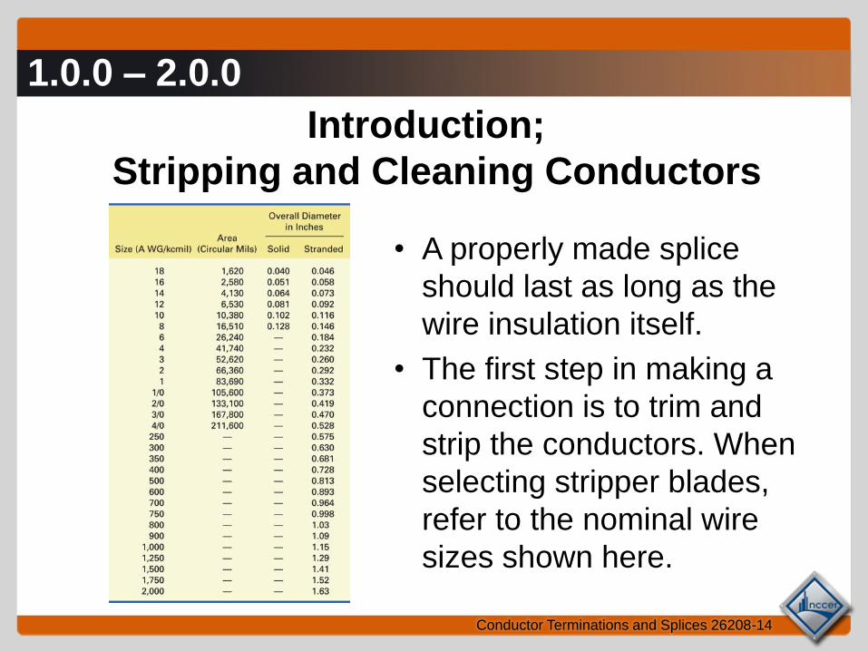
Introduction;
Stripping and Cleaning Conductors
• A properly made splice
should last as long as the
wire insulation itself.
• The first step in making a
connection is to trim and
strip the conductors. When
selecting stripper blades,
refer to the nominal wire
sizes shown here.

2.1.0
Conductor Terminations and Splices 26208-14
Stripping Small Conductors
• The wire strippers shown here can be used to strip
wires from No. 22 through No. 10 AWG.
• Match the conductor size to the correct knife groove,
then insert the conductor and squeeze the tool handles.
The length of the stripped conductor is determined by
the amount extending beyond the blades.
2.1.0
Conductor Terminations and Splices 26208-14
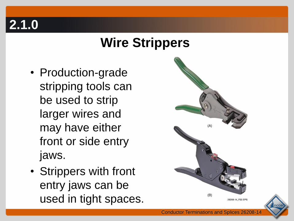
Wire Strippers
• Production-grade
stripping tools can
be used to strip
larger wires and
may have either
front or side entry
jaws.
• Strippers with front
entry jaws can be
used in tight spaces.
2.2.0
Conductor Terminations and Splices 26208-14
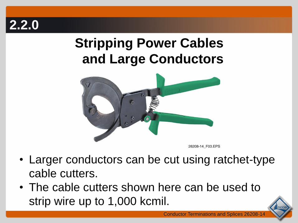
Stripping Power Cables
and Large Conductors
• Larger conductors can be cut using ratchet-type
cable cutters.
• The cable cutters shown here can be used to
strip wire up to 1,000 kcmil.
2.2.0
Conductor Terminations and Splices 26208-14
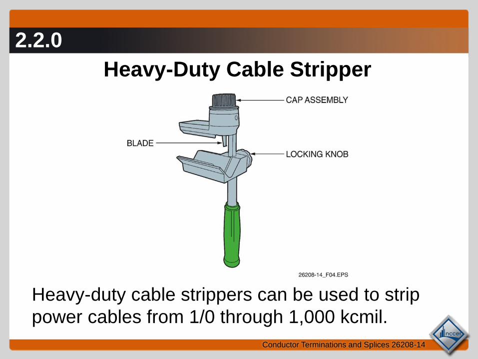
Heavy-Duty Cable Stripper
Heavy-duty cable strippers can be used to strip
power cables from 1/0 through 1,000 kcmil.

2.2.0
Conductor Terminations and Splices 26208-14
Types of Cable Stripping
• Strippers can be used to strip
the end insulation or to make
window cuts.
• Follow the manufacturer’s
instructions to avoid personal
injury or conductor damage.

2.2.0
Conductor Terminations and Splices 26208-14
Round Cable Slitting and Ringing Tool
• This tool can be used to strip single- or multi-
conductor cable.
• It can make both square (circumferential) cuts
or lengthwise (longitudinal) cuts.
2.3.0
Conductor Terminations and Splices 26208-14
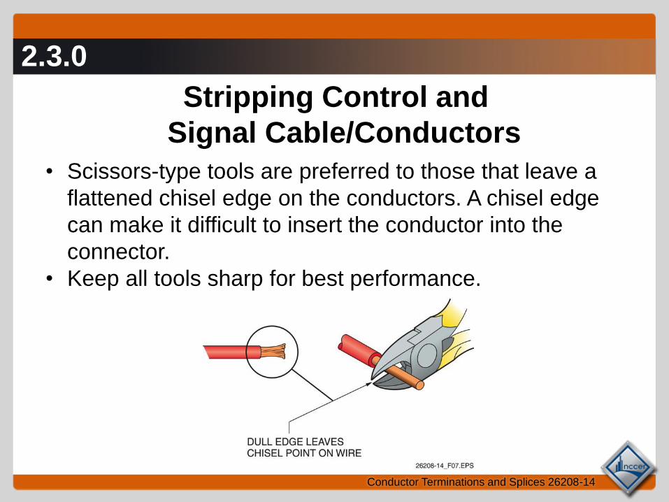
Stripping Control and
Signal Cable/Conductors
• Scissors-type tools are preferred to those that leave a
flattened chisel edge on the conductors. A chisel edge
can make it difficult to insert the conductor into the
connector.
• Keep all tools sharp for best performance.
2.3.0
Conductor Terminations and Splices 26208-14
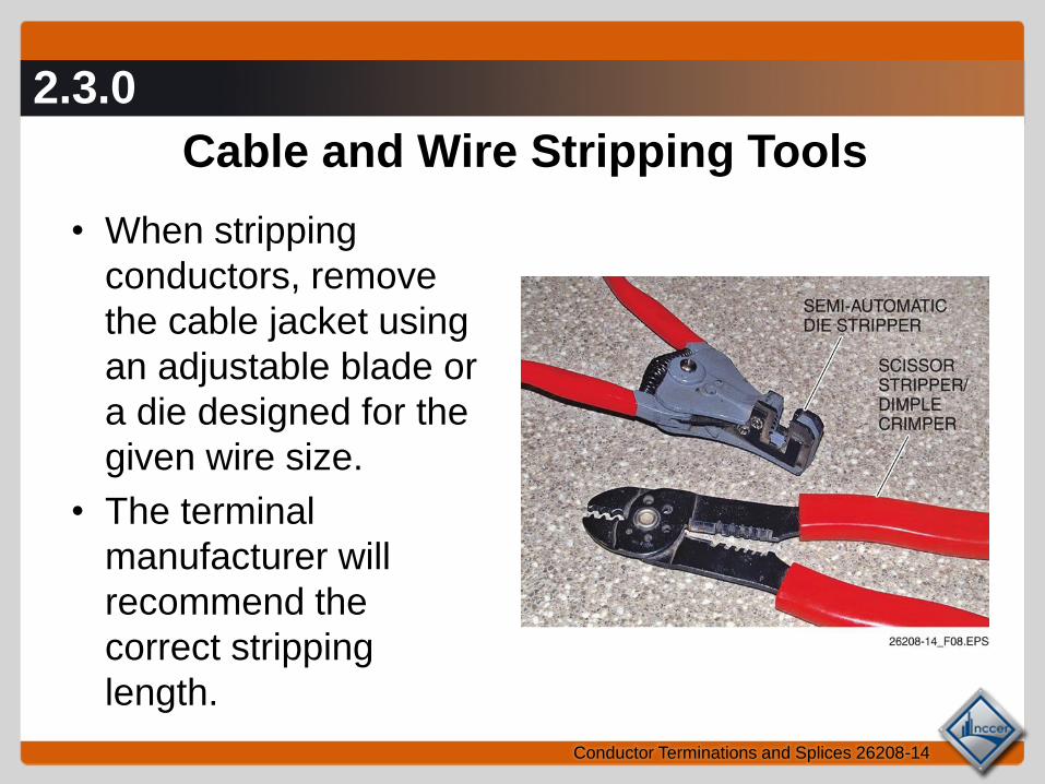
Cable and Wire Stripping Tools
• When stripping
conductors, remove
the cable jacket using
an adjustable blade or
a die designed for the
given wire size.
• The terminal
manufacturer will
recommend the
correct stripping
length.

2.3.0
Conductor Terminations and Splices 26208-14
Proper Stripping Length

3.0.0 – 3.1.0
Conductor Terminations and Splices 26208-14
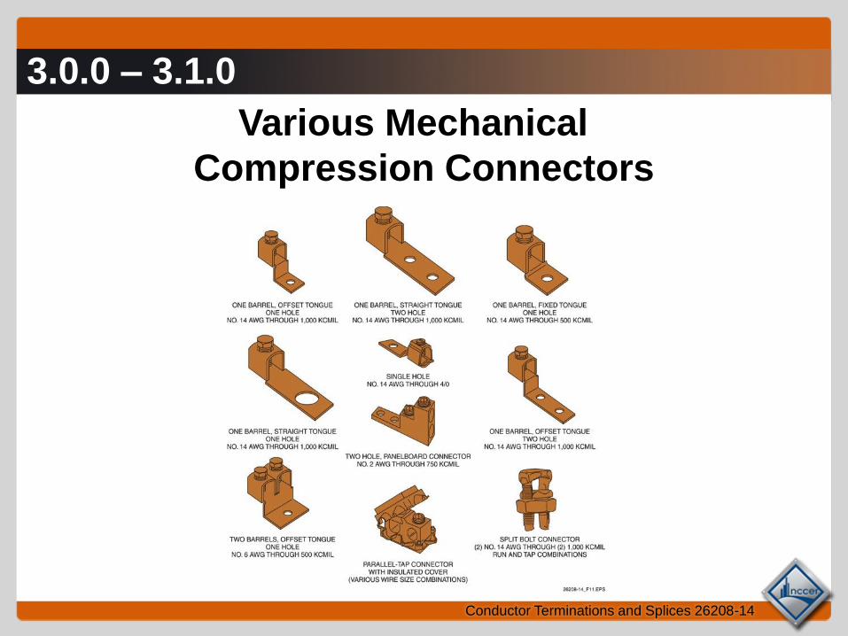
Wire Connections Under 600 Volts • Crimp-on wire lugs are
available in various sizes
to accommodate wire
sizes No. 22 AWG and
larger. They are normally
color coded for ease of
identification.
• A variety of mechanical
compression connectors
are also available. These
include various screw-on
lugs and split-bolt
connectors.
3.0.0 – 3.1.0
Conductor Terminations and Splices 26208-14
Various Mechanical
Compression Connectors
3.2.0
Conductor Terminations and Splices 26208-14
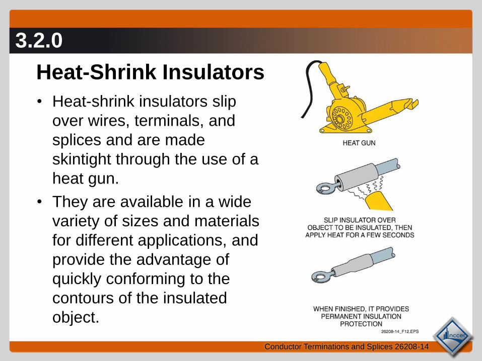
Heat-Shrink Insulators
• Heat-shrink insulators slip
over wires, terminals, and
splices and are made
skintight through the use of a
heat gun.
• They are available in a wide
variety of sizes and materials
for different applications, and
provide the advantage of
quickly conforming to the
contours of the insulated
object.
3.2.0
Conductor Terminations and Splices 26208-14
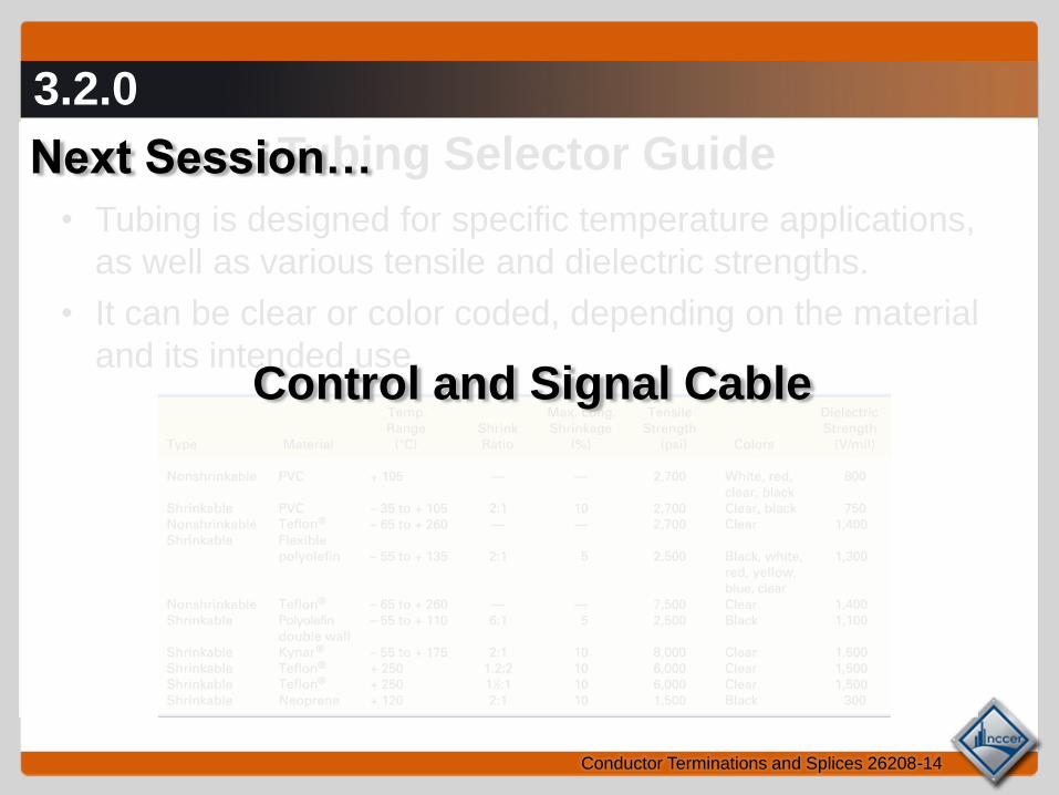
Tubing Selector Guide
• Tubing is designed for specific temperature applications,
as well as various tensile and dielectric strengths.
• It can be clear or color coded, depending on the material
and its intended use.
Next Session…
Control and Signal Cable
4.0.0 – 4.2.0
Conductor Terminations and Splices 26208-14
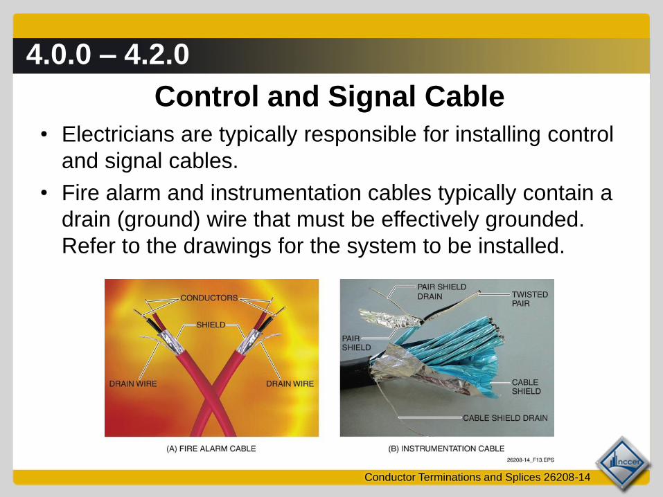
Control and Signal Cable
• Electricians are typically responsible for installing control
and signal cables.
• Fire alarm and instrumentation cables typically contain a
drain (ground) wire that must be effectively grounded.
Refer to the drawings for the system to be installed.
5.0.0 – 5.1.0
Conductor Terminations and Splices 26208-14
Low-Voltage Connectors and Terminals
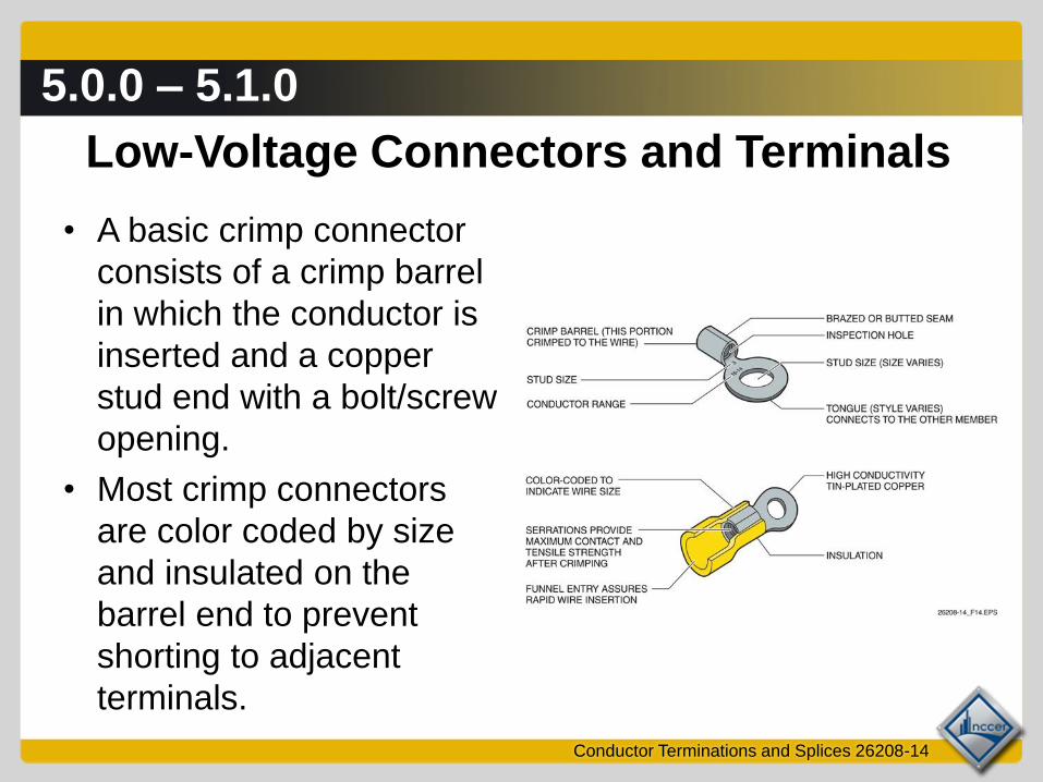
• A basic crimp connector
consists of a crimp barrel
in which the conductor is
inserted and a copper
stud end with a bolt/screw
opening.
• Most crimp connectors
are color coded by size
and insulated on the
barrel end to prevent
shorting to adjacent
terminals.
5.0.0 – 5.1.0
Conductor Terminations and Splices 26208-14
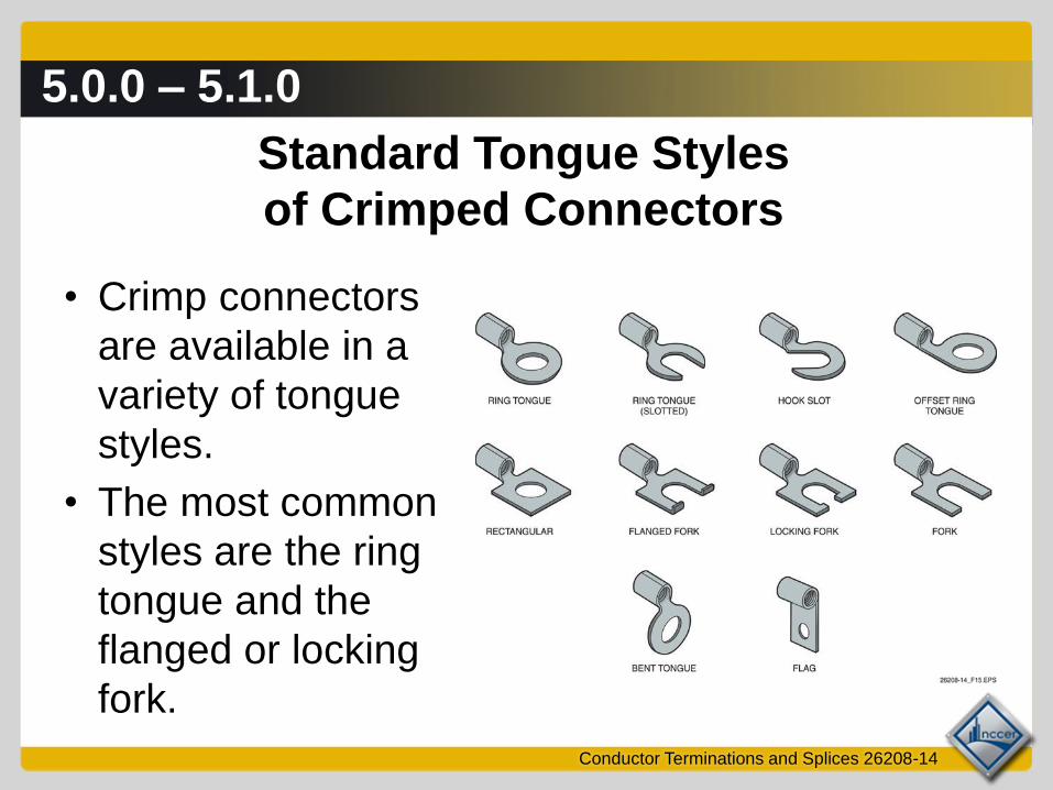
Standard Tongue Styles
of Crimped Connectors
• Crimp connectors
are available in a
variety of tongue
styles.
• The most common
styles are the ring
tongue and the
flanged or locking
fork.

5.2.0
Conductor Terminations and Splices 26208-14
Color Codes
• Color codes may vary by manufacturer, but certain
color standards have become common.
• Typical crimp connector color codes are shown
here.

6.0.0 – 6.2.0
Conductor Terminations and Splices 26208-14
Guidelines for Installing Connectors
• Review the project
drawings and
specifications before
making any line
connections.
• Always use the correct tool
for the connector and the
wire size. Failure to do so
can result in damaged
conductors and poorly
made connections.

6.0.0 – 6.2.0
Conductor Terminations and Splices 26208-14
Hand Crimpers
Pliers-type hand crimpers are used with smaller wires or
when only a few connections are required.

6.0.0 – 6.2.0
Conductor Terminations and Splices 26208-14
Leveraged Crimping Tool
• A leveraged tool provides a
mechanical advantage
through the use of a ratchet
control.
• This type of tool multiplies
the crimping force for a
better connection and has
interchangeable dies for use
with various terminal sizes.

6.0.0 – 6.2.0
Conductor Terminations and Splices 26208-14
Crimping Tools Used
to Crimp Large Connectors
• The tools used to crimp large
connectors supply crimping
forces of about 12 tons of
compression at 10,000
pounds per square inch (psi).
• These tools are available in
hand-operated, hydraulic,
battery-operated, and corded
types.

6.0.0 – 6.2.0
Conductor Terminations and Splices 26208-14
Battery-Operated Crimping Tool

6.0.0 – 6.2.0
Conductor Terminations and Splices 26208-14
Corded Crimping Tool

6.0.0 – 6.2.0
Conductor Terminations and Splices 26208-14
Universal Crimping Tool
Universal crimping tools offer an advantage in that they
can fit a variety of terminations without the need for
separate dies.
6.0.0 – 6.2.0
Conductor Terminations and Splices 26208-14
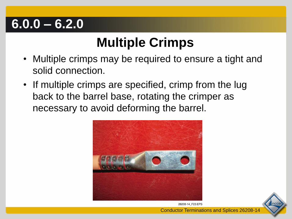
Multiple Crimps
• Multiple crimps may be required to ensure a tight and
solid connection.
• If multiple crimps are specified, crimp from the lug
back to the barrel base, rotating the crimper as
necessary to avoid deforming the barrel.

6.0.0 – 6.2.0
Conductor Terminations and Splices 26208-14
Recommended Tightening Torques
for Various Bolt Sizes • After the conductor has
been crimped in the
connector, the connector
must be bolted to the
required torque to ensure a
good electrical connection
at the termination.
• Common torque values are
shown here.
Performance Task
Trainees practice terminating conductors using selected crimp-
type and mechanical-type terminals and connectors.
6.3.0
Conductor Terminations and Splices 26208-14
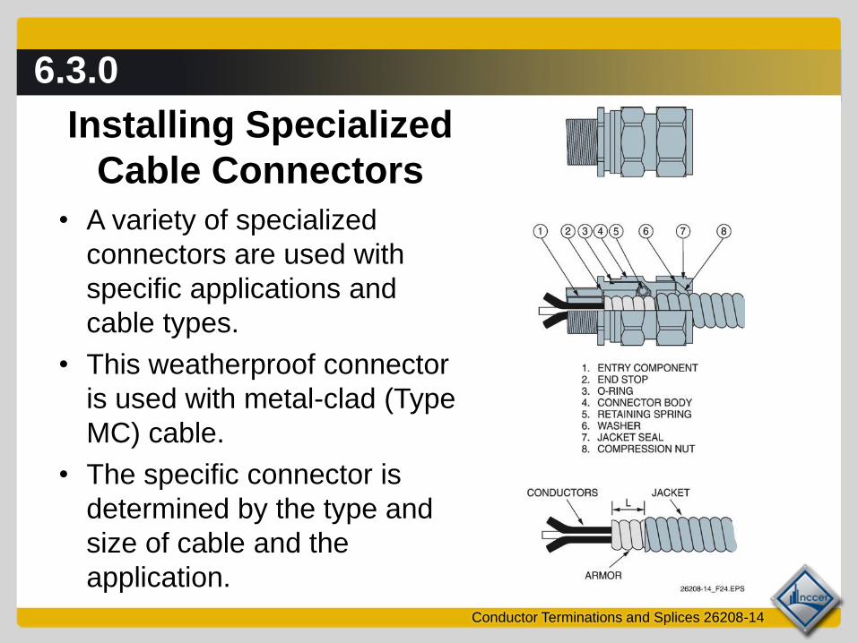
Installing Specialized
Cable Connectors
• A variety of specialized
connectors are used with
specific applications and
cable types.
• This weatherproof connector
is used with metal-clad (Type
MC) cable.
• The specific connector is
determined by the type and
size of cable and the
application.
6.4.0 – 6.4.4
Conductor Terminations and Splices 26208-14
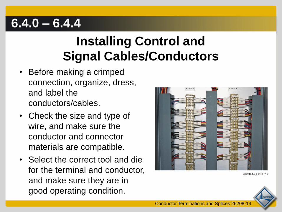
Installing Control and
Signal Cables/Conductors • Before making a crimped
connection, organize, dress,
and label the
conductors/cables.
• Check the size and type of
wire, and make sure the
conductor and connector
materials are compatible.
• Select the correct tool and die
for the terminal and conductor,
and make sure they are in
good operating condition.
6.4.0 – 6.4.4
Conductor Terminations and Splices 26208-14
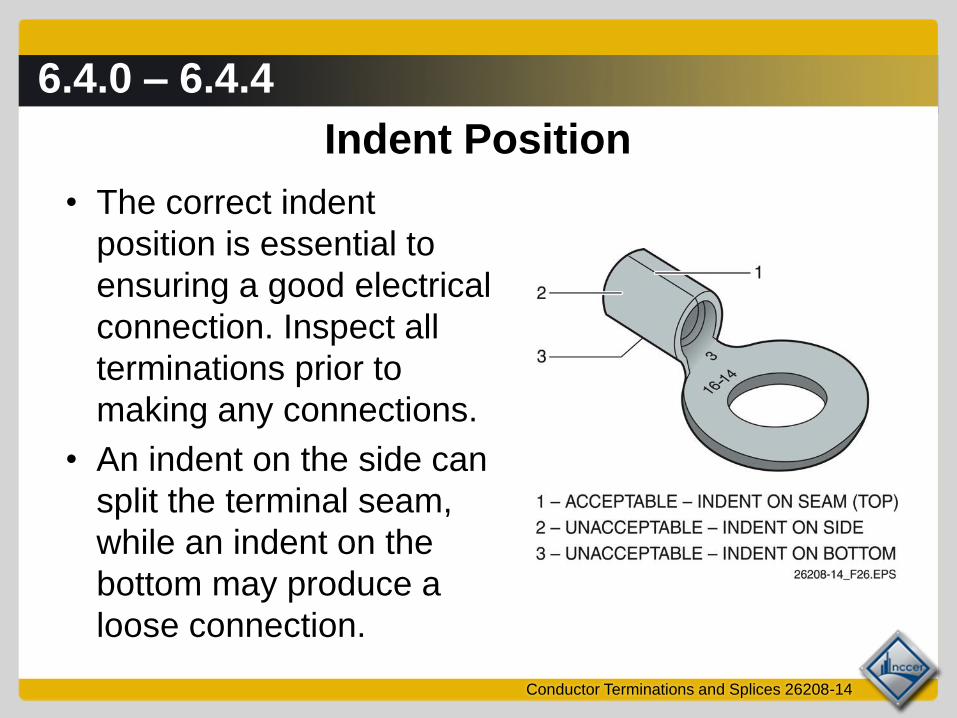
Indent Position
• The correct indent
position is essential to
ensuring a good electrical
connection. Inspect all
terminations prior to
making any connections.
• An indent on the side can
split the terminal seam,
while an indent on the
bottom may produce a
loose connection.

6.4.0 – 6.4.4
Conductor Terminations and Splices 26208-14
Crimp Centering
• The conductor must be
properly centered in the
crimp indent.
• A crimp over the belled
mouth will compress the
insulation and result in
poor or no continuity.
• A crimp over the
inspection hole reduces
both continuity and
holding capacity.
6.4.0 – 6.4.4
Conductor Terminations and Splices 26208-14
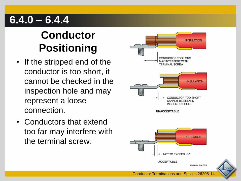
Conductor
Positioning
• If the stripped end of the
conductor is too short, it
cannot be checked in the
inspection hole and may
represent a loose
connection.
• Conductors that extend
too far may interfere with
the terminal screw.

6.4.0 – 6.4.4
Conductor Terminations and Splices 26208-14
Terminal Blocks
• Terminal blocks are available with a variety of connection
types.
• Clamp-type, spring-loaded, and screw-type terminal
blocks are common.

6.4.0 – 6.4.4
Conductor Terminations and Splices 26208-14
Routing Cabling
• When multiple cables
are installed, tie them
neatly to a support
without blocking access
to other terminal blocks.
• Take care to avoid
routing cable over sharp
edges or at tight angles.
• To minimize interference,
avoid wire crossovers
whenever possible.

6.4.0 – 6.4.4
Conductor Terminations and Splices 26208-14
Terminal Bend Radius
Do not bend terminals more
than 30 degrees above or
below the termination point.
Performance TaskTrainees practice terminating
conductors on a terminal strip.
7.0.0
Conductor Terminations and Splices 26208-14
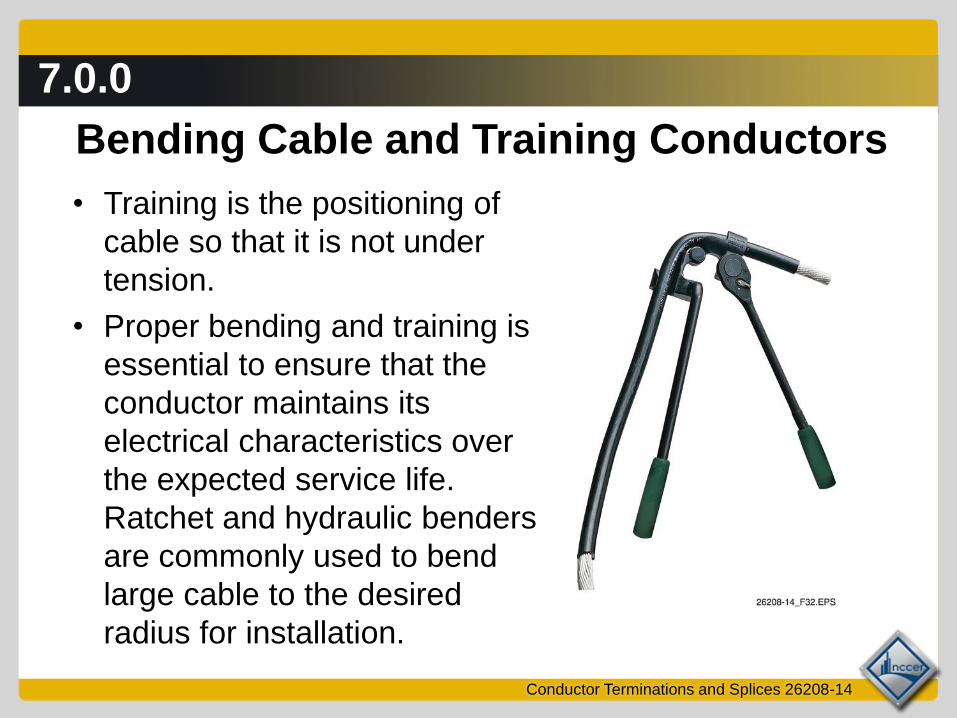
Bending Cable and Training Conductors
• Training is the positioning of
cable so that it is not under
tension.
• Proper bending and training is
essential to ensure that the
conductor maintains its
electrical characteristics over
the expected service life.
Ratchet and hydraulic benders
are commonly used to bend
large cable to the desired
radius for installation.
7.0.0
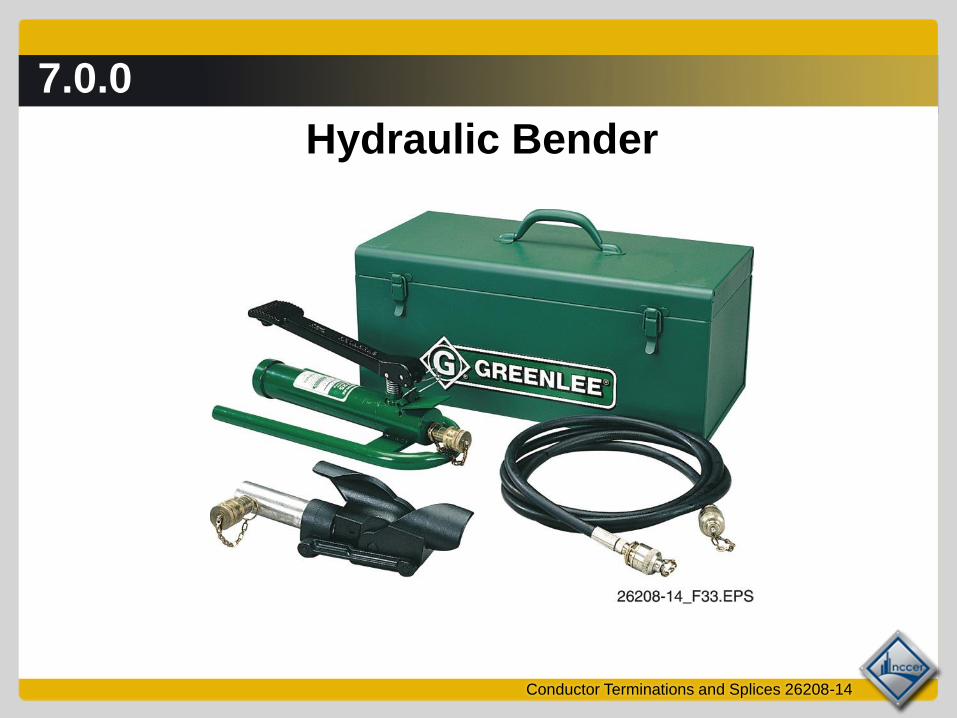
Conductor Terminations and Splices 26208-14
Hydraulic Bender
7.0.0
Conductor Terminations and Splices 26208-14
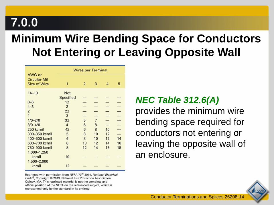
Minimum Wire Bending Space for Conductors
Not Entering or Leaving Opposite Wall
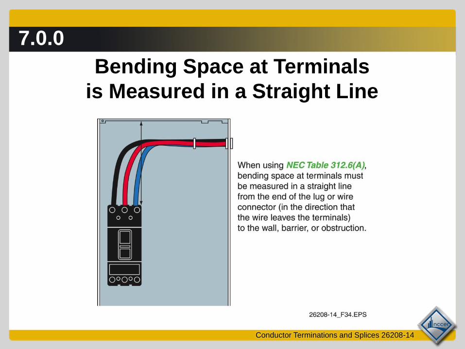
NEC Table 312.6(A)
provides the minimum wire
bending space required for
conductors not entering or
leaving the opposite wall of
an enclosure.
7.0.0
Conductor Terminations and Splices 26208-14
Bending Space at Terminals
is Measured in a Straight Line

7.0.0
Conductor Terminations and Splices 26208-14
Conductors Entering an Enclosure
Opposite the Conductor Terminals

7.0.0
Conductor Terminations and Splices 26208-14
Minimum Wire Bending Space for Conductors
Entering or Leaving Opposite Wall
NEC Table 312.6(B)
provides the minimum
wire bending space
required for conductors
entering or leaving the
opposite wall of an
enclosure.
8.0.0 – 8.1.3
Conductor Terminations and Splices 26208-14
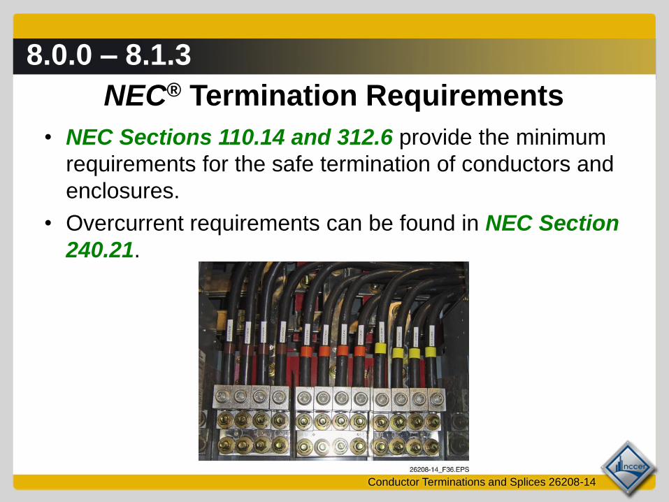
NEC® Termination Requirements
• NEC Sections 110.14 and 312.6 provide the minimum
requirements for the safe termination of conductors and
enclosures.
• Overcurrent requirements can be found in NEC Section
240.21.

8.0.0 – 8.1.3
Conductor Terminations and Splices 26208-14
MCC Fed Directly from a
Transformer Secondary Next Session…
Taping Electrical Joints

9.0.0
Conductor Terminations and Splices 26208-14
Taping Electrical Joints

9.0.0
Conductor Terminations and Splices 26208-14
Typical Method of Taping a Split-Bolt Connector

9.0.0
Conductor Terminations and Splices 26208-14
Motor Connection Kits
• Motor connection kits are available to insulate bolted
splice connections.
• These kits eliminate the need for taping and the use of
filler tape or putty.
9.0.0
Motor Connection Kits
Installed on Splices
Conductor Terminations and Splices 26208-14
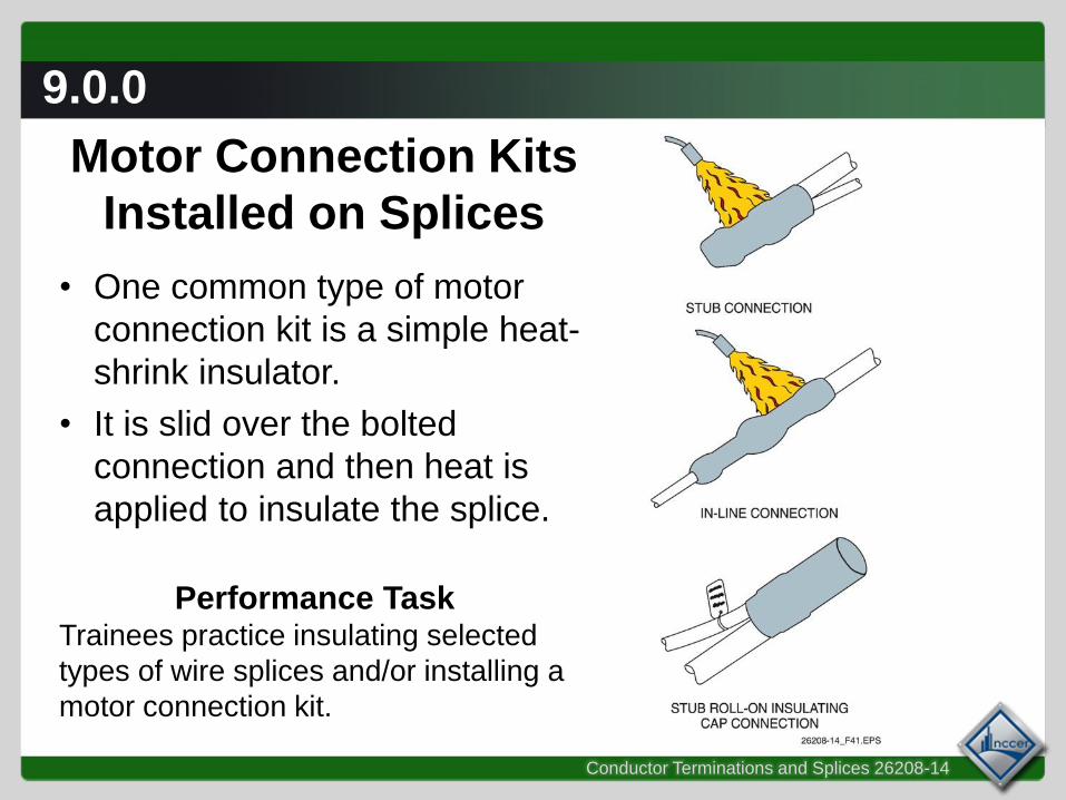
• One common type of motor
connection kit is a simple heat-
shrink insulator.
• It is slid over the bolted
connection and then heat is
applied to insulate the splice.
Performance TaskTrainees practice insulating selected
types of wire splices and/or installing a
motor connection kit.
Wrap Up
– Write important things learned during class
– Write questions you have about the material
– Write thought you had about the material
Conductor Terminations and Splices 26208-14

Next Session…
MODULE EXAM
Review the complete module to prepare
for the module exam. Complete the Module
Review as a study aid.
Conductor Terminations and Splices 26208-14