electrical installation f1is/f2is, f1i/f2i, flfm1is, … f… · atesteo gmbh electrical...
TRANSCRIPT

Electrical Installation F1iS/F2iS, F1i/F2i, FLFM1iS, FLFM1eS
Version 2016 / 07
Stator All-In-One

ATESTEO GmbH
Electrical Installation F1iS/F2iS, F1i/F2i, FLFM1iS, FLFM1eS 2/72
Electrical Installation F1iS/F2iS, F1i/F2i, FLFM1iS, FLFM1eS
ATESTEO GmbH
Konrad-Zuse-Str. 3
52477 Alsdorf
T +49 (0) 2404 9870-0
F +49 (0) 2404 9870-59
www.atesteo.com

ATESTEO GmbH
Electrical Installation F1iS/F2iS, F1i/F2i, FLFM1iS, FLFM1eS 3/72
Dear customer,
before leaving our company every unit is tested by extensive function
and quality examinations, which guarantee that the system complies
with the stated specifications. Nevertheless should there be any
problem, please contact us.
Before shipping a system, the serial numbers of each component of
your configuration is registered by our company, so that an individual
and short-term support can be guaranteed. It is understood that we will
inform you about innovations and modifications of the system.
Guarantee
ATESTEO takes over the Guarantee for the legislative prescribed time.
All the reparations will be done in this time without calculation
executed. Any damage, which is caused by equipment usage, cannot be
as guarantee case valid.

ATESTEO GmbH
Electrical Installation F1iS/F2iS, F1i/F2i, FLFM1iS, FLFM1eS 4/72
F1iS / F2iS
F1i / F2i
FLFM1iS
FLFM1eS

ATESTEO GmbH
Electrical Installation F1iS/F2iS, F1i/F2i, FLFM1iS, FLFM1eS 5/72
Content
1 Description ...................................................................................................................................... 7
2 Safety Instructions .......................................................................................................................... 8
3 Introduction ..................................................................................................................................... 9
3.1 One-channel telemetry (FM) F1i/F2i .............................................................................................. 10
3.2 Dual -Telemetry DT (FM/ FM) F1i/F2i ............................................................................................ 11
1 Electrical Installation .................................................................................................................... 13
3.1 Mains Supply .................................................................................................................................. 13
3.2 Earthing .......................................................................................................................................... 13
3.3 Connecting the Evaluation Unit / Torquemeter with a Data Acquisition System ........................... 13
3.4 Accident Prevention ....................................................................................................................... 14
4 First Installation ............................................................................................................................ 15
4.1 First Installation FiS/F2iS ............................................................................................................... 15
4.1.3 Changing the Torquemeter ............................................................................................................. 15
4.2 Terminal Setting ............................................................................................................................. 19
4.2.3 Terra Term Setup ............................................................................................................................ 19
4.3 Setting up the Calibration Parameters ........................................................................................... 21
5 Configuration ................................................................................................................................. 23
5.1 Software TCUConfig ...................................................................................................................... 23
5.1.3 Setup Inductive Power Supply ........................................................................................................ 25
5.1.4 Torque zero adjustment .................................................................................................................. 25
5.1.5 Setup the calibration parameters .................................................................................................... 25
5.1.6 Setup Analog Output ....................................................................................................................... 26
5.1.7 Setup Current Output ...................................................................................................................... 26
5.1.8 Setup Filter ...................................................................................................................................... 27
5.1.9 Setup Alarm .................................................................................................................................... 27
5.1.10 Setup CAN Interface ....................................................................................................................... 28
5.2 Terminal Program .......................................................................................................................... 31
5.3 Main Menu ..................................................................................................................................... 31
5.3.1 Filter Settings .................................................................................................................................. 32
5.3.2 Alarm Settings ................................................................................................................................. 33
5.3.3 Output Settings ............................................................................................................................... 34
5.3.4 Torquemeter settings ...................................................................................................................... 36
5.3.5 Read parameters ............................................................................................................................ 38
5.3.6 Selftest ............................................................................................................................................ 39
5.3.7 Analog setup ................................................................................................................................... 40
5.3.8 CAN setup ....................................................................................................................................... 41
6 Use of the Control signal / status ................................................................................................ 47
6.1 Selftest ........................................................................................................................................... 47
6.2 Zero calibration .............................................................................................................................. 48
6.3 Test signal ...................................................................................................................................... 48

ATESTEO GmbH
Electrical Installation F1iS/F2iS, F1i/F2i, FLFM1iS, FLFM1eS 6/72
7 LED status ..................................................................................................................................... 49
7.1 Green LED ..................................................................................................................................... 49
7.2 Red LED ......................................................................................................................................... 49
8 Digital Interface ............................................................................................................................. 50
8.1 Alarm Md/N .................................................................................................................................... 50
8.2 Alarm IR ......................................................................................................................................... 50
8.3 Reset Alarm ................................................................................................................................... 50
9 Plug connection ............................................................................................................................ 51
9.1 Plug connection F1iS/F2iS, FLFM1iS, FLFM1eS .......................................................................... 51
9.2 Plug connection F1i/F2i ................................................................................................................. 53
9.3 Electrical specifications .................................................................................................................. 55
9.3.3 RS422 Outputs................................................................................................................................ 55
9.3.4 Alarm Outputs ................................................................................................................................. 55
9.3.5 Control Input .................................................................................................................................... 56
9.3.6 Analog Outputs A/B ........................................................................................................................ 56
9.3.7 Analog Output C.............................................................................................................................. 57
9.3.8 Current Output ................................................................................................................................ 57
9.3.9 RS232 ............................................................................................................................................. 57
9.3.10 CAN ................................................................................................................................................. 58
10 General references ....................................................................................................................... 59
10.1 Overvoltage protection ................................................................................................................... 59
10.2 Torquemeter without Test Signal ................................................................................................... 59
10.3 Hotline ............................................................................................................................................ 59
10.4 Flash update .................................................................................................................................. 60
11 Calibration of the Torquemeter ................................................................................................... 61
12 Recommendations for resetting the zero point of a ATESTEO Torque measuring flange ... 67
12.1 Thermal influences ......................................................................................................................... 67
12.2 Hysteresis-caused influences ........................................................................................................ 67
12.3 Aging .............................................................................................................................................. 67
12.4 Lateral force influence .................................................................................................................... 67
12.5 General .......................................................................................................................................... 68
13 EC Manufacturer’s Declaration: .................................................................................................. 69

ATESTEO GmbH
Electrical Installation F1iS/F2iS, F1i/F2i, FLFM1iS, FLFM1eS 7/72
1 Description
The iS torque measurement systems are representing a further development of the new generation of
torquemeters with integrated evaluation unit. With the exception of a 24VDC power supply, no external
components are required for operation.
High-end temperature compensation guarantees very good stability and repeatability of the output signals.
The standard model is equipped with an inductive one track speed measurement system.
For your convenience the torquemeters of the iS series are interchangeable with the same stator.
Specifications
Power Supply 24V DC max. 1A
Sample Rate Torque 1000 Samples / Second
Sample Rate Speed f > 1000 Hz 1000 Samples / Second
Sample Rate Speed f < 1000 Hz f / 2 Samples / Second
Lowest Frequency, which can be
measured
5Hz
(the output for frequencies <5Hz is 0Hz)
Analog Output Range selectable 0..5V, 0..10V, -5..+5V, -10..+10V
Analog Output Signal Resolution 16 bit
Analog Output Impedance 50 Ohm
Optional Current Output (Torque) selectable 4..20mA, 0..20mA
Filter Torque: 1st-order IIR-Filter with 6 fixed cut-off
frequencies
Speed: Moving Averager with adjustable filter depth
CAN Interface CAN2B
Identifier free adjustable
max. 1MBaud
max. 1000 messages/channel/second
Serial port RS232, 19200 Baud, 8 Data Bit, No Parity Bit,
1 Stop Bit, No Protocol
Frequency outputs RS422
Torque
Inductive speed sensor
Magnetic speed sensor (optional)

ATESTEO GmbH
Electrical Installation F1iS/F2iS, F1i/F2i, FLFM1iS, FLFM1eS 8/72
2 Safety Instructions
Before setting-up operation, maintenance or additional handling of the measurement system, it
is important to review the following:
Review any safety procedures including the operation manual.
Check that all protective devices are installed and functioning properly.
Note on additional standards:
Low Voltage Directive 73/23/EWG, Electromagnetic Compatibility
Directive 89/336/EWG and the harmonized standards
DIN EN 292-1 Safety of machinery
DIN EN 292-2 Safety of machinery
Maintenance and inspections on the electrical equipment are to be executed by trained
personal. Non-designated use and modifications of the measurement system will make the
EG-Conformity declaration invalid.

ATESTEO GmbH
Electrical Installation F1iS/F2iS, F1i/F2i, FLFM1iS, FLFM1eS 9/72
3 Introduction
In this manual you will find all steps which are necessary to start-up the ATESTEO torque and speed
measurement system.
This manual is usable for the following types of torque meters:
Torquemeter F1iS
Torquemeter F2iS
Torquemeter F1i
Torquemeter F2i
Torquemeter FLFM1iS
Torquemeter FLFM1eS
All measurement systems work contactless and are maintenance-free. The data transmission is realized by a
frequency modulated infrared transmitter. The power of the rotating electronic module works inductive.

ATESTEO GmbH
Electrical Installation F1iS/F2iS, F1i/F2i, FLFM1iS, FLFM1eS 10/72
3.1 One-channel telemetry (FM) F1i/F2i
Features:
frequency output proportional to torque 60 kHz 20 kHz
analogue output [V] proportional to torque with 1000 readings/s
frequency output proportional to speed
analogue output [V] proportional to speed
shunt – calibration
Zero adjustment automatically via remote control
serial Interface RS232
CAN 2B interface

ATESTEO GmbH
Electrical Installation F1iS/F2iS, F1i/F2i, FLFM1iS, FLFM1eS 11/72
T
D
(temperature values)
16 bit
EEPROM
D D
F
F
A A
+V
IR-TRANSMISSION 1
IR-TRANSMISSION 2
+V
3.2 Dual -Telemetry DT (FM/ FM) F1i/F2i
The overall system is created to integrate a second amplifier and a second IR-telemetry during the
production of the torque meter. This second amplifier amplifies the signal from the strain gage bridge with a
very high accuracy. The result is a second range of highly precise measurement of small torques.
Consequently, the often necessary replacement of the torque sensor for the highly precise measurement of
less torques can be dropped. This second measuring system also includes a temperature compensation and
a shunt calibration as in the first one.(see illustration).
To exploit the total measuring preciseness of the minor measuring range one must
consider, to stop and unload the power train after each measuring cycle, which takes place
under a high torque load. Afterwards the systems needs to be reset to "0" otherwise the
hysteresis figures, recorded in the spring body, would overlap
the more sensitive second measuring channel.
With the Dual –Telemetry system (FM/FM) it is possible to measure with one torquemeter high and small
torques with a high accuracy.

ATESTEO GmbH
Electrical Installation F1iS/F2iS, F1i/F2i, FLFM1iS, FLFM1eS 12/72
Features:
2 x frequency output proportional to torque 60 kHz 20 kHz
frequency output proportional to speed
analogue output [V] proportional to torque with 1000 readings/s
analogue output [V] proportional to speed
shunt – calibration
Zero adjustment automatically via remote control
System-parameter via RS232.
CAN 2B interface

ATESTEO GmbH
Electrical Installation F1iS/F2iS, F1i/F2i, FLFM1iS, FLFM1eS 13/72
1 Electrical Installation
The parts delivered are dependant upon customer specific orders. If you have ordered a complete
measurement system, all electrical and software parameters are pre-installed.
3.1 Mains Supply
The purchased ATESTEO measuring systems F1iS/F2iS, F1i/F2i, FLFM1iS, FLFM1iS,
FLFM1eS have to be powered with DC voltage of 24-30V / 1A. The power input depends
on the sensor system. The power consumption lies between 4 and 10 watts. The power
supply must be protected with a 1AT fuse against overcurrent.
3.2 Earthing
The housing of the evaluation unit has an earth connection. The internal ground is separated from that earth.
The torque meter must be connected to the earth of the test bench for proper working. The shielding of the
connecting cables is connected to the connectors at both ends.
3.3 Connecting the Evaluation Unit / Torquemeter with a Data Acquisition System
To keep the EMV – Norm EN61000-6-4 / VDE 0839 parts 6-4, the following procedure to handle the
connecting cable is recommended.
Please use shielded servo cable with 4x 2x 0.14mm² (twisted pair) + 4x 0,5mm² wire for the connection to
X750 and shielded servo cable with 8x 2x 0.25mm² wire (twisted pair) for the connection to X 751/752.
The shielding of the cable must be connected to the connectors on both ends.

ATESTEO GmbH
Electrical Installation F1iS/F2iS, F1i/F2i, FLFM1iS, FLFM1eS 14/72
The following grounding scheme is recommended:
The shielding must be connected on both sides (torquemeter and measuring rack).
3.4 Accident Prevention
The usage of the equipment assumes keeping the general safety regulations in mind!
Test bench
Stator
Power 24V
Receiver
RS422
Central
Frame Ground
Measuring rack
Connect shielding
shielding
Frame Ground

ATESTEO GmbH
Electrical Installation F1iS/F2iS, F1i/F2i, FLFM1iS, FLFM1eS 15/72
4 First Installation
4.1 First Installation FiS/F2iS
ATTENTION!!!
If you have purchased a complete torque measurement system consisting of a torquemeter and a
corresponding stator, you may skip the following articles. Otherwise the following adjustments of the
default settings are absolutely necessary to properly run the system!
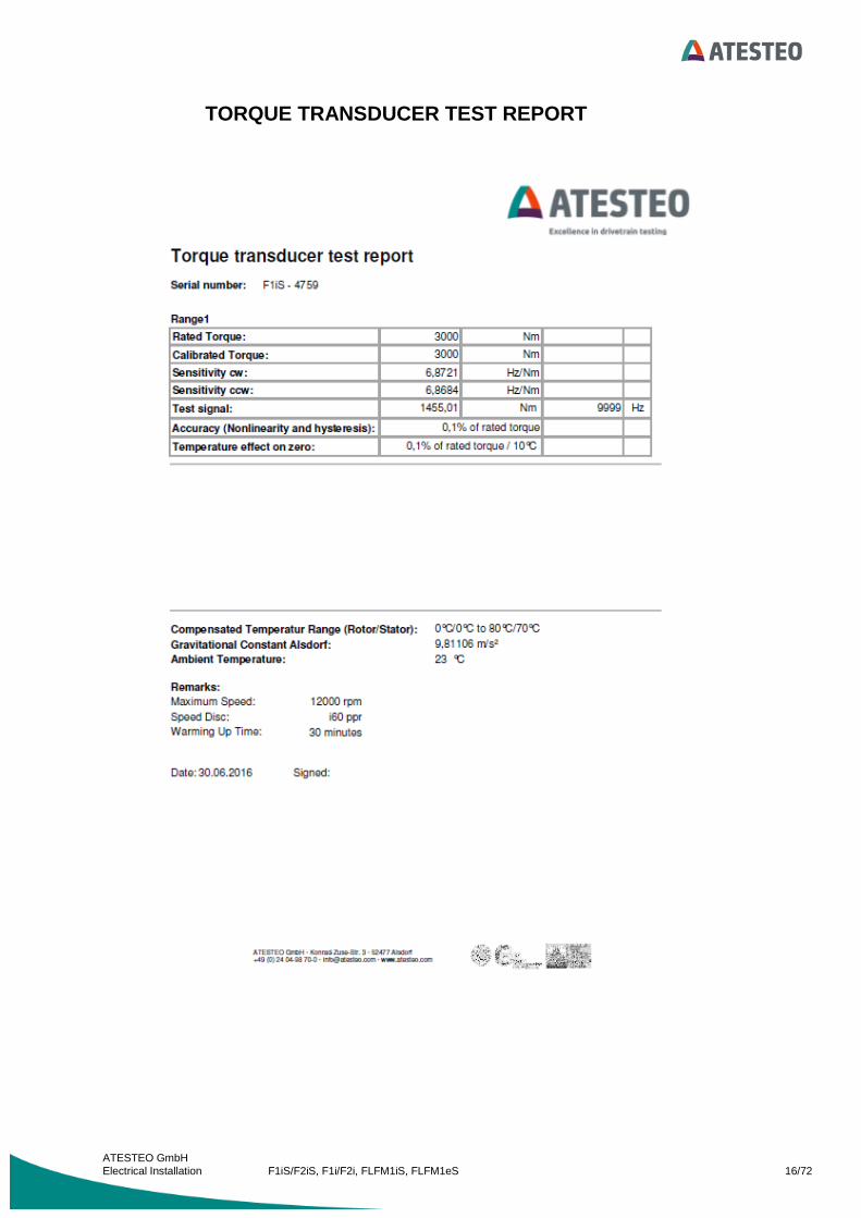
4.1.3 Changing the Torquemeter
For your convenience the torquemeters of the F1iS series are interchangeable with the same stator. All you
need is to enter the parameters supported by the 'Torque Transducer Test Report' which is delivered with the
new torquemeter.
ATESTEO GmbH
Electrical Installation F1iS/F2iS, F1i/F2i, FLFM1iS, FLFM1eS 16/72
TORQUE TRANSDUCER TEST REPORT

ATESTEO GmbH
Electrical Installation F1iS/F2iS, F1i/F2i, FLFM1iS, FLFM1eS 17/72
First Installation F1i/F2i
With every torque meter you get a torque transducer test report.
These parameters must be saved via the RS232 interface into the stator.
The electronic unit for measuring and transmission of torque is placed in the measuring flange. The unit is
supplied by a reference voltage of 10VDC. For a good voltage stability, the input voltage should be about
15V. The shunt calibration switch is closed at an input voltage above 17V. In normal operation mode the
frequency of the infrared data stream is 60 kHz 20 kHz.
ATESTEO GmbH
Electrical Installation F1iS/F2iS, F1i/F2i, FLFM1iS, FLFM1eS 18/72
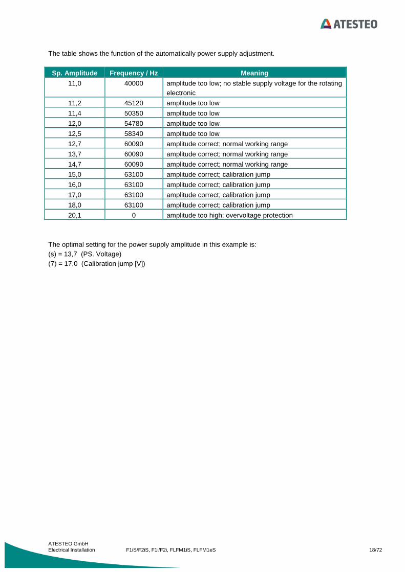
The table shows the function of the automatically power supply adjustment.
Sp. Amplitude Frequency / Hz Meaning
11,0 40000 amplitude too low; no stable supply voltage for the rotating
electronic
11,2 45120 amplitude too low
11,4 50350 amplitude too low
12,0 54780 amplitude too low
12,5 58340 amplitude too low
12,7 60090 amplitude correct; normal working range
13,7 60090 amplitude correct; normal working range
14,7 60090 amplitude correct; normal working range
15,0 63100 amplitude correct; calibration jump
16,0 63100 amplitude correct; calibration jump
17,0 63100 amplitude correct; calibration jump
18,0 63100 amplitude correct; calibration jump
20,1 0 amplitude too high; overvoltage protection
The optimal setting for the power supply amplitude in this example is:
(s) = 13,7 (PS. Voltage)
(7) = 17,0 (Calibration jump [V])

ATESTEO GmbH
Electrical Installation F1iS/F2iS, F1i/F2i, FLFM1iS, FLFM1eS 19/72
4.2 Terminal Setting
4.2.3 Terra Term Setup
This program is a freeware and you can find it on the delivered CD.
Font setup:
Terminal setup:

ATESTEO GmbH
Electrical Installation F1iS/F2iS, F1i/F2i, FLFM1iS, FLFM1eS 20/72
Serial port setup:

ATESTEO GmbH
Electrical Installation F1iS/F2iS, F1i/F2i, FLFM1iS, FLFM1eS 21/72
4.3 Setting up the Calibration Parameters
Connect the Torquemeter F1iS/F2iS, F1i/F2i, FLFM1iS oder FLFM1eS to the serial interface (RS232 19200
Baud, 8bit, no parity, no protocol).
To activate the serial interface press the key '#', then press 'T' to enter the torquemeter setup menu.
With the terminal program you can set up the parameters for the connected torquemeter. Take the
parameters (1, 2, 3, b) from the torque transducer test report and fill in the properties as shown.
TORQUE TRANSDUCER TEST REPORT
P/N: 4831 Serial number S/N : F1iS - 1721
Range1
Rated Torque 500 Nm Calibrated Torque 500 Nm
Sensitivity clockwise 38.9442 Hz/Nm related to calibrated torque
Sensitivity anticlockwise 38.9365 Hz/Nm
Calibration Jump 255.75 Nm 9960 Hz
Sensitivity clockwise = Sensitivity+
Sensitivity anticlockwise = Sensitivity-

ATESTEO GmbH
Electrical Installation F1iS/F2iS, F1i/F2i, FLFM1iS, FLFM1eS 22/72
After these steps the frequency Md1 must be about 60000 Hz.
With each new installation (Torquemeter/Stator) it is recommended to adjust the inductive power supply. The
amplitude of the inductive power supply can be automatically set up by pressing 'y'.
Press 'y' for automatic inductive power
supply adjustment.

ATESTEO GmbH
Electrical Installation F1iS/F2iS, F1i/F2i, FLFM1iS, FLFM1eS 23/72
5 Configuration
5.1 Software TCUConfig
Connect the Torquemeter to the serial interface. Install the program TCUConfig on your PC and start the
program.
The TCUConfig program scans all ports after you press Search. Select the port which is connected to the
torquemeter. It is also possible to work offline with the setup program. In this case you can store a parameter
list for later use.
If you have some Bluetooth interfaces or other measurement equipment at the serial port it can be that the
Search routine doesn’t work and the program hang up. In this case select only the used serial port.

ATESTEO GmbH
Electrical Installation F1iS/F2iS, F1i/F2i, FLFM1iS, FLFM1eS 24/72
After selecting the right port an overview of all settings is shown.

ATESTEO GmbH
Electrical Installation F1iS/F2iS, F1i/F2i, FLFM1iS, FLFM1eS 25/72
5.1.3 Setup Inductive Power Supply
Service – Setup Inductive Power Supply
The stator searches for the right settings of the inductive power supply. If everything is o.k. the frequency of
the torque signal is about 60000 Hz. In the menu “Service Setup inductive Power Supply” it is possible to
activate this operation by hand.
5.1.4 Torque zero adjustment
With a right click on the torque value it is possible to show the frequency and to set the torque to 0 Nm.
Please use torque = 0 only if you 100% sure, that the torquemeter is free of torque.
5.1.5 Setup the calibration parameters
Fill in the form showed above with the parameters from the Torque Transducer Test Report. These
parameters are very important to get the right physical values at the analogue output, the display and the
CAN Interface.

ATESTEO GmbH
Electrical Installation F1iS/F2iS, F1i/F2i, FLFM1iS, FLFM1eS 26/72
5.1.6 Setup Analog Output
The torquemeters F1iS/F2iS, F1i/F2i, FLFM1iS, FLFM1eS include up to three (A/B/C) analogue outputs.
Here it is possible to select different signals for the analog outputs. You can get your F1iS / F2iS with a lot of
options. Whichever is the installed option the menu shows different choices for the analog output.
For Out1 / Out2 it is possible to select between:
Torque 1 Filter A
Torque 1 Filter B
Speed
It is not possible to show the same channel on both outputs.
The output range can be selected between:
-10V to 10V
-5V to 5V
0 to 5V
0 to 10V
For circuit details and sample circuits please refer to chapter „Electrical specifications“.
5.1.7 Setup Current Output
The current output can be switched on or off in this edit menu. Moreover, it is possible to select between 0-
20mA and 4-20 mA. If the current output was used, then the analog output A isn’t available anymore.

ATESTEO GmbH
Electrical Installation F1iS/F2iS, F1i/F2i, FLFM1iS, FLFM1eS 27/72
5.1.8 Setup Filter
Filters, which are used here, acting on analogue and CAN outputs, but not on frequency outputs.
For the torque signals the both filters are available. So one filter can be use for the automation system and
the other for the measuring equipment. The filter A und B for the torque signal are IIR Filter and the filter for
the speed signals are moving average filter.
5.1.9 Setup Alarm
Here it is possible to setup the alarm limits for the speed signal and the torque signal.
For circuit details and sample circuits please refer to chapter „Electrical specifications“.

ATESTEO GmbH
Electrical Installation F1iS/F2iS, F1i/F2i, FLFM1iS, FLFM1eS 28/72
5.1.10 Setup CAN Interface

ATESTEO GmbH
Electrical Installation F1iS/F2iS, F1i/F2i, FLFM1iS, FLFM1eS 29/72
Please select the right parameter which corresponds with your measuring equipment.
You can choose here which signals at CAN-BUS have to be displayed and with witch data rates.
The value of the output data depends on the selected format and the measured value. When the data format
'long' is selected, the measured values are multiplied by a certain factor to retain decimal places. Thus the
received data must be divided by that factor by the acquisition system to get back the measured data.
Measured Value: float Measured Value: long (x factor) Unit
Speed inductive Speed inductive x 10 rpm
Speed magnetic\optical Speed magnetic \optical x 10 rpm
Torque Torque x 1000 Nm
Torque Min/Max (int) Torque Min/Max (int) x 10 Nm
Speed Min/Max (int) Speed Min/Max (int) x 10 rpm
Temperature Stator Temperature Stator x 1000 °C
Status (long) Status
Alarm (long) Alarm
This table shows the possible data which can be sent by the CAN interface. Every CAN message consists of
an identifier and two different measured values. For each pair of measured values you can select a separate
data transmit interval.

ATESTEO GmbH
Electrical Installation F1iS/F2iS, F1i/F2i, FLFM1iS, FLFM1eS 30/72
As the example above the following message will be send:
Long 0 1 100 values / s
Integer 0 1 2 3
Byte 0 1 2 3 4 5 6 7
Speed Max/Min Torque Max/Min Identifier ID 0x109
ATESTEO GmbH
Electrical Installation F1iS/F2iS, F1i/F2i, FLFM1iS, FLFM1eS 31/72
5.2 Terminal Program
If the program “TCUConfig” is not more available, you can conduct all the settings using the Terminal
Program.
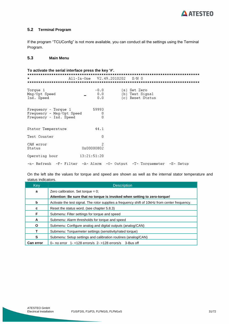
5.3 Main Menu
To activate the serial interface press the key '#'.
On the left site the values for torque and speed are shown as well as the internal stator temperature and
status indicators.
Key Description
a Zero calibration. Set torque = 0;
Attention: Be sure that no torque is invoked when setting to zero-torque!
b Activate the test signal. The rotor supplies a frequency shift of 10kHz from center frequency.
c Reset the status word. (see chapter 5.8.3)
F Submenu: Filter settings for torque and speed
A Submenu: Alarm thresholds for torque and speed
O Submenu: Configure analog and digital outputs (analog/CAN)
T Submenu: Torquemeter settings (sensitivity/rated torque)
S Submenu: Setup settings and calibration routines (analog/CAN)
Can error 0– no error 1- <128 errors/s 2- >128 errors/s 3-Bus off

ATESTEO GmbH
Electrical Installation F1iS/F2iS, F1i/F2i, FLFM1iS, FLFM1eS 32/72
5.3.1 Filter Settings
Different digital filters can be activated in stator.
Two independent IIR filters are dedicated to the torque channel with 6 different cut-
off frequencies.
One moving average filter is provided for F1i/F2i, F1iS/F2iS installed speed sensor.
(The magnetic speed sensor as shown in the picture below is optionally available).
Key Description
1 Cut-off frequency (-3dB) of filter A for torque measurement Filter settings: -0- off -1- 250Hz -2- 150Hz -3- 100Hz -4- 50Hz -5- 10Hz -6- 1Hz
2 Cut-off frequency (-3dB) of filter B for torque measurement.
(Filter settings see above)
3 Moving-average filter depth for the inductive speed sensor (standard).
-0- off
4 Moving-average filter depth for the magnetic speed sensor (optional).

ATESTEO GmbH
Electrical Installation F1iS/F2iS, F1i/F2i, FLFM1iS, FLFM1eS 33/72
5.3.2 Alarm Settings
It is important to take care of the maximum safe operating conditions specified for the torquemeter. Not only
to prevent the rotor from damage due to hazardous operating states but also to protect the test bench
against demolition.
Alarm thresholds can be set for the maximum approvable torque and speed. The alarm signal is provided
through open collector outputs at the 16 pole connector X752 and as CAN messages.
For circuit details and sample circuits please refer to chapter „Electrical specifications“.
Key Description
'1' Alarm threshold max. torque
'2' Alarm threshold min. torque
'3' Alarm threshold max. speed (inductive and magnetic)
'4' Alarm threshold min. speed (inductive and magnetic)

ATESTEO GmbH
Electrical Installation F1iS/F2iS, F1i/F2i, FLFM1iS, FLFM1eS 34/72
5.3.3 Output Settings
The measured values of torque and speed can be outputted as analog signals and as CAN messages
simultaneously. It is possible to choose between the different filter types to set up each output channel
individually.
Three analog outputs are available.
Channels A and B are selectable for torque and speed output with different voltage output ranges defined.
Analog output A can be switched to a current loop whereby it is no longer available as calibrated voltage
output. Hence the current output takes its place.
Channel C provides the internal stator temperature or status information about the stator. An output voltage
level of 4.9V represents a faultless operation whereas a voltage of 0.1V is representing an error and the
torquemeter has to be checked.
If the outputted voltage drops below 0.1V a line break occurred.
Voltage analog output C Description
<0.1V Cable break. Check electrical connection
0.1V Error! Check the status word by software to determine the error
condition.
4.9V No error.
The CAN message configuration is simply performed by entering an identifier and a transmit interval for the
referred signal. A minimum time interval of 1ms can be chosen. The number of totally transmitted data per
second is limited by the bus speed of CAN, so the current set data rate is calculated and displayed as
'Current Message rate'. The predetermined maximum message rate can neither be crossed nor altered. For
the CAN bus settings refer to chapter “CAN”.
If the mounted speed sensor is not in selecton, it can be activated with the “TCUConfig” software, Menu
„Service“ „Setup Speed Sensor“ or in Terminal „output settings“ „x“.
For circuit details and sample circuits please refer to chapter „Electrical specifications“.
Key Description

ATESTEO GmbH
Electrical Installation F1iS/F2iS, F1i/F2i, FLFM1iS, FLFM1eS 35/72
'a', 'b' Select signal for analog output A/B
-0- Md1 Filter A
-1- Md1 Filter B
-2- N mag Filter (optional)
-3- N ind Filter
'1'..'7' CAN message identifier
'f'..'l' CAN transmit interval
'x' Installed speed sensors.
Current
Message
rate
Maximum configurable message rates
1Mbps 6500msg/s
500kbps 3700msg/s
250kbps 1850msg/s
125kbps 1000msg/s
100kbps 800msg/s
10kbps 76msg/s

ATESTEO GmbH
Electrical Installation F1iS/F2iS, F1i/F2i, FLFM1iS, FLFM1eS 36/72
5.3.4 Torquemeter settings
To adapt a torquemeter to an evaluation unit the calibration parameters obtained from the 'Torque
Transducer Test Report' must be correctly filled out in the 'Torquemeter Settings' menu. The frequency
registered as 'Zero Output' is acquired when performing a zero calibration [ (a) Set Zero) ].

ATESTEO GmbH
Electrical Installation F1iS/F2iS, F1i/F2i, FLFM1iS, FLFM1eS 37/72
Key Description
'b' Serial number. The Serial number from the enclosed torquemeter is shown.
'1' Sensitivity + characteristic value: torquemeter torque clockwise (pos)
'2' Sensitivity - characteristic value: torquemeter torque anticlockwise (neg)
'3' Rated Torque
'x' Number of pulses per revolution of the inductive speed sensor (fixed by
mechanical design of the torquemeter)
'z' Impulses per revolution (speed measuring system)
'm' Maximum speed
Full scale value of analog output
'7' Zero Output (Zero frequency)
This value is automatically acquired when performing a zero calibration
'9' Calibration Jump [V]
Necessary inductive power supply amplitude to engage the test signal.
This parameter is calculated automatically and must not be altered by the user!
'0' Calibration Jump [Hz]
Test signal frequency shift in Hz.
This parameter is calculated automatically and must not be altered by the user!
'p' PS. on/off
Turn inductive power supply on/off.
's' PS. Voltage
Voltage amplitude of the inductive power supply.
'y' PS. Auto voltage
Automatically setup the inductive power supply.
The following parameters are assigned
(s) PS. Voltage
(7) Zero Output
(9) Calibration Jump [V]
(0) Calibration Jump [Hz]
'a' Zero calibration. Set torque = 0; Attention: Be sure that no torque is invoked
when setting to zero-torque!
'r' Read parameters stored into the rotor electronics.
'S' Perform selftest of the measuring system

ATESTEO GmbH
Electrical Installation F1iS/F2iS, F1i/F2i, FLFM1iS, FLFM1eS 38/72
5.3.5 Read parameters
The calibration parameters can be obtained from the 'Torque Transducer Test Report' as well as read out of
the torquemeter electronics itself. After the transfer procedure is performed the user is prompted to setup the
evaluation unit with the read values.
After pressing the key 'Y’, the parameters received from the torquemeter will be stored into the evaluation
unit (Staror).

ATESTEO GmbH
Electrical Installation F1iS/F2iS, F1i/F2i, FLFM1iS, FLFM1eS 39/72
5.3.6 Selftest
The selftest can be used to perform a test routine verifying the rudimentary functions of the measurement
system. The following settings will be checked:
inductive power supply settings
Comparing the saved serial number with the received serial number. If the serial numbers are
different, then the new values for the sensitivity will be saved automatically.
Stability test of the inductive power supply.
If an error occurs it is indicated by the status word supplied by the evaluation unit.

ATESTEO GmbH
Electrical Installation F1iS/F2iS, F1i/F2i, FLFM1iS, FLFM1eS 40/72
5.3.7 Analog setup
To adapt the analog outputs of the evaluation unit to a data acquisition system it is possible to adjust the
voltage offset and the voltage output range. The current loop output range is selectable between 0..20mA
and 4..20mA.
Note: The analog outputs are pre-calibrated during the production process of the evaluation unit. It is
not recommended to recalibrate the analog outputs by untrained personal.
For circuit details and sample circuits please refer to chapter „Electrical specifications“.
'A'..'C' Calibration of the analogue outputs. The calibration parameters were determined by
ATESTEO and have been saved into the unit. No calibration is needed!
'1'..'3' It is possible to set a offset voltage for each analog output.
'5', '6' Here it is possible to set a offset voltage for each analogue output.
'9' Attention: If activated the voltage output of channel A is not scaled!
'0' Select the output range of the current loop output.
'I' Calibration of the current loop output. The calibration parameters were determined by
ATESTEO and have been saved into the unit. No calibration is needed!
‘4’ (for
F1i/F2i) The Input Control is used to switch between the two channels of a dual range torquemeter

ATESTEO GmbH
Electrical Installation F1iS/F2iS, F1i/F2i, FLFM1iS, FLFM1eS 41/72
5.3.8 CAN setup
The CAN bus setup enables the user to adapt the torquemeter CAN interface to an existing CAN topology
supported by the customer. It is not only possible to alter system parameters such as speed and identifier
length but also to choose between different byte orders and message formats. For circuit details and sample
circuits please refer to chapter „Electrical specifications“.

ATESTEO GmbH
Electrical Installation F1iS/F2iS, F1i/F2i, FLFM1iS, FLFM1eS 42/72
Key Description
'1' If activated, the defined messages will be transmitted (activate data transmission)
'2' CAN bus speed
-1000- 1Mbps
-500- 500kbps
-250- 250kbps
-125- 125kbps
-100- 100kbps
-10- 10kbps
'3' Length of the message identifiers
-11- 11 bit
-29- 29 bit
'4' Numeric format transmitted in a message
-long- 32bit signed integer
-float- 32bit IEEE754 floating point value
'5' Byte order inside a CAN message
-Intel- The data transfer begins with the least significant byte.
-Motorola- The data transfer begins with the most significant byte.
'6' The CAN identifier dedicated to the command messages the stator receives to be
externally controlled.

ATESTEO GmbH
Electrical Installation F1iS/F2iS, F1i/F2i, FLFM1iS, FLFM1eS 43/72
With the following messages it is possible to control the evaluation unit:
Note: The values must be sent as "long" even if "float" is selected as numeric data format. The right identifier
length (11 or 29 Bit) must be set.
Identifier: 11Bit / 29Bit
Long 0 1
Integer 0 1 2 3
Byte 0 1 2 3 4 5 6 7
0 2000 CAN message transmission start
0 2001 CAN message transmission stop
0 1201
Zero calibration.
Attention: Be sure that no
torque is invoked when setting
to zero-torque!
0 1202 Activate test signal
0 1203 Deactivate test signal
0 1211 Reset status
0 1212 Read status
0 1213 Read serial number of
torquemeter
0 1214 Perform selftest
Reply from torquemeter (rx-identifier + 1)
Long 0 1
Integer 0 1 2 3
Byte 0 1 2 3 4 5 6 7
Last command X
Read serial number:
Reply from torquemeter (rx-identifier + 1)
Long 0 1
Integer 0 1 2 3
Byte 0 1 2 3 4 5 6 7
Last command Serial number

ATESTEO GmbH
Electrical Installation F1iS/F2iS, F1i/F2i, FLFM1iS, FLFM1eS 44/72
Read status:
Reply from torquemeter (rx-identifier + 1)
Long 0 1
Integer 0 1 2 3
Byte 0 1 2 3 4 5 6 7
Last command Status
Status 32 Bit (format long)
ST
Bit 7
ST
Bit 6
ST
Bit 5
ST
Bit 4
ST
Bit 3
ST
Bit 2
ST
Bit 1
ST
Bit 0
Selfte
st active
Sele
ctio
n 1
Sele
ctio
n 0
Err
or
1
Err
or
0
Overf
low
Zero
po
int re
set
Test sig
na
l
15 14 13 12 11 10 9 8 7 6 5 4 3 2 1 0
Sim
ula
tion
Ala
rm IR
Ala
rm N
min
Ala
rm N
max
Ala
rm M
d m
in
Ala
rm M
d m
ax
31 30 29 28 27 26 25 24 23 22 21 20 19 18 17 16
Alarm 32 Bit (format long)
Ala
rm IR
Ala
rm N
min
Ala
rm N
max
Ala
rm M
d m
in
Ala
rm M
d m
ax
15 14 13 12 11 10 9 8 7 6 5 4 3 2 1 0
(Upper 16 Bits not used. Read out as zeroes)

ATESTEO GmbH
Electrical Installation F1iS/F2iS, F1i/F2i, FLFM1iS, FLFM1eS 45/72
Min/Max (format int)
Speed Minimum Speed Maximum
31 16 15 0
Torque Minimum Torque Maximum
63 48 47 32
After the zero point calibration procedure the status bit ‘zero point reset’ is set. It can only be cleared by
resetting the status word. With the help of the error code it is possible to check whether the command is
accomplished successfully or not.
Error 0/1:
Error 1 Error 0
0 1 Zero point reset not possible
1 0 No calibration jump
Selection 0/1:
Selection 1 Selection 0
0 0 Md1 / N1
0 1 Md2 / N1
1 0 Md1 / Md2

ATESTEO GmbH
Electrical Installation F1iS/F2iS, F1i/F2i, FLFM1iS, FLFM1eS 46/72
ST bits:
ST
Bit7
ST
Bit6
ST
Bit5
ST
Bit4
ST
Bit3
ST
Bit2
ST
Bit1
ST
Bit0
1 SP + 0,5V
Md1 not stable
1 SP + 0,5V
Md1 not stable
1 SP CAL
No calibration jump
1 Selftest not active
1 Found new values for
inductive power supply
1 Same serial number
different sensitivity
1 Can’t read
sensitivity
1 New torquemeter installed
New sensitivity saved

ATESTEO GmbH
Electrical Installation F1iS/F2iS, F1i/F2i, FLFM1iS, FLFM1eS 47/72
6 Use of the Control signal / status
The input, Control can be used to release the selftest, to reset the zero point and to engage the test signal. If
Analog out C is set to status it provides the status information about the stator. An output voltage level of
4.9V represents a faultless operation whereas a voltage of 0.1V is representing an error and the torquemeter
has to be checked.
If the outputted voltage drops below 0.1V a line break occurred.
For circuit details and sample circuits please refer to chapter „Electrical specifications“.
6.1 Selftest
no yes Analog output C =
4.9V
Test torquemeter
Analog output C = 0.1V
Control = 24V
set for 3 seconds
Test of the inductive power supply
Test of the torquemeter (shunt calibration)
All tests
O.K.
Analog output C =
0.1V

ATESTEO GmbH
Electrical Installation F1iS/F2iS, F1i/F2i, FLFM1iS, FLFM1eS 48/72
6.2 Zero calibration
Set Control for 5 seconds. With the falling edge of the input signal the zero point is calibrated.
6.3 Test signal
Set Control for 7 seconds. After 7 seconds the test signal will be engaged as long as the signal has a voltage
level of 24V. By setting Control=0V the test signal will be disabled.
ATESTEO GmbH
Electrical Installation F1iS/F2iS, F1i/F2i, FLFM1iS, FLFM1eS 49/72
7 LED status
7.1 Green LED
In normal mode the green LED is blinking with a frequency of 1 Hz indicating the evaluation unit is powered
up. LED ist blinking faster during the start-up phase when the supply voltage is automatically adjusted (Auto
Setup = 0).
7.2 Red LED
As long as the evaluation unit operates faultlessly the red LED is not lighting. If an error occurs (e.g. alarm
threshold exceeded) the LED lights continuously. If the rotor sends no signal, or the automatic search for the
power-supply amplitude is engaged, or the data transfer between stator and rotor is in progress the red LED
is blinking.

ATESTEO GmbH
Electrical Installation F1iS/F2iS, F1i/F2i, FLFM1iS, FLFM1eS 50/72
8 Digital Interface
8.1 Alarm Md/N
If the alarm thresholds have been exceeded due to overload or over-speed the open collector outputs "Alarm
Md" and "Alarm N" are set. The digital outputs are open-collector types, so that the measured output signal
is inverted. The maximum collector-emitter voltage is maximum rated with 36V (50mA).
For circuit details and sample circuit please refer to chapter „Electrical specifications“.
8.2 Alarm IR
If the data transmission between the rotor and the stator can no longer be guaranteed faultless, the output
"Alarm IR" is set. The degree of failure is observed by monitoring the intensity of infrared-light being
transmitted. The threshold is factory calibrated and cannot be altered.
For circuit details and sample circuit please refer to chapter „Electrical specifications“.
8.3 Reset Alarm
If alarm thresholds are exceeded the corresponding digital output is set. With the help of the input "Reset
Alarm" it is possible to reset the alarms being displayed. The status bits are also cleared when using this
feature. Apply a voltage >4V to trigger the reset function. The maximum input voltage is rated with 30V.
For circuit details and sample circuit please refer to chapter „Electrical specifications“.

ATESTEO GmbH
Electrical Installation F1iS/F2iS, F1i/F2i, FLFM1iS, FLFM1eS 51/72
9 Plug connection
9.1 Plug connection F1iS/F2iS, FLFM1iS, FLFM1eS
X750
12 polig female
Conivers
combined
power-supply
measurement signals
RS422
Md – Torque
N - Speed
1 N inductive -
2 N inductive +
3 N2+ (magnetic/optional)
4 N2- (magnetic/optional)
5 N1+ (magnetic/optional)
6 N1- (magnetic/optional)
7 Mdf1-
8 Mdf1+
9 Control
10 VCC 24V
11 GND (24V)
12 GND (24V)
X 751/752
16 pole male
Conivers
combinated
anlog/digital
measurement Signals
Md – Torque
N - Speed
1 TXD RS232
2 RXD RS232
3 Ground
4 Ground
5 CANH
6 CANL
7 MD I out
8 Analogout B
9 Analogout C
10 Analogout A
11 Alarm Md
12 Ground
13 Alarm N
14 Alarm IR
15 Reset Alarm (in)
16 DT2 (in)

ATESTEO GmbH
Electrical Installation F1iS/F2iS, F1i/F2i, FLFM1iS, FLFM1eS 52/72
Connecting Cable F1iS / F2iS, FLFM1iS, FLFM1eS
12 pole Conivers Plug Female
1 RS422 N inductive- twisted pair 0.14mm²
white
2 RS422 N inductive+ brown
3 RS422 N2+ twisted pair 0.14mm²
grey
4 RS422 N2- pink
5 RS422 N1+ twisted pair 0.14mm²
blue
6 RS422 N1- red
7 RS422 Mdf1- twisted pair 0.14mm²
yellow
8 RS422 Mdf1+ green
9 Control 0.5mm² white
10 U in 24V 2A 0.5mm² green
11 GND 0.5mm² yellow
12 GND 0.5mm² brown
LI-2YC11Y 250V si/gr 4x0.5+4x2x0.14
16 pole Conivers Plug Male
1 RS232 TXD twisted pair 0.25mm²
white
2 RS232 RXD brown
3 GND twisted pair 0.25mm²
green
4 GND yellow
5 CANH twisted pair 0.25mm²
grey
6 CANL pink
7 MD I out twisted pair 0.25mm²
blue
8 Analogout B red
9 Analogout C twisted pair 0.25mm²
black
10 Analogout A violet
11 Alarm Md twisted pair 0.25mm²
grey/pink
12 GND red/blue
13 Alarm N twisted pair 0.25mm²
white/green
14 Alarm IR grown/green
15 Reset Alarm twisted pair 0.25mm²
white/yellow
16 DT2 in yellow/brown
LIYCY 250V 8x2x0.25
ATESTEO GmbH
Electrical Installation F1iS/F2iS, F1i/F2i, FLFM1iS, FLFM1eS 53/72
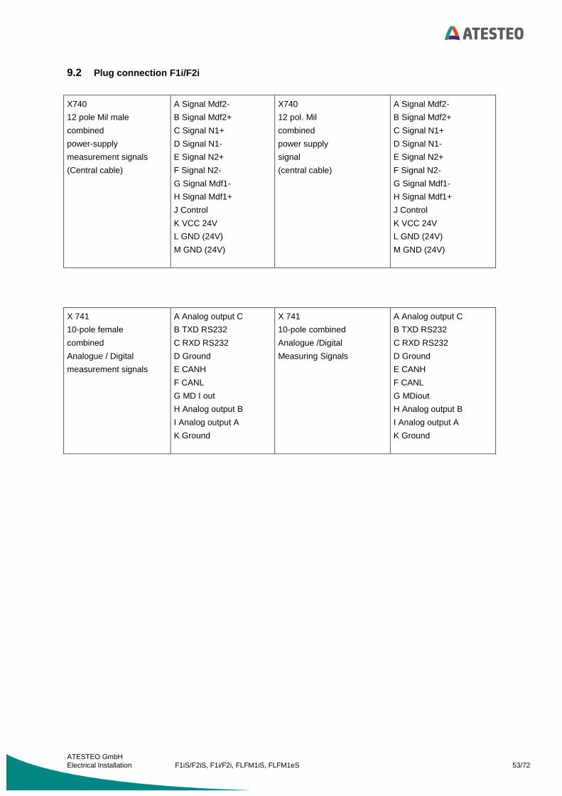
9.2 Plug connection F1i/F2i
X740
12 pole Mil male
combined
power-supply
measurement signals
(Central cable)
A Signal Mdf2-
B Signal Mdf2+
C Signal N1+
D Signal N1-
E Signal N2+
F Signal N2-
G Signal Mdf1-
H Signal Mdf1+
J Control
K VCC 24V
L GND (24V)
M GND (24V)
X740
12 pol. Mil
combined
power supply
signal
(central cable)
A Signal Mdf2-
B Signal Mdf2+
C Signal N1+
D Signal N1-
E Signal N2+
F Signal N2-
G Signal Mdf1-
H Signal Mdf1+
J Control
K VCC 24V
L GND (24V)
M GND (24V)
X 741
10-pole female
combined
Analogue / Digital
measurement signals
A Analog output C
B TXD RS232
C RXD RS232
D Ground
E CANH
F CANL
G MD I out
H Analog output B
I Analog output A
K Ground
X 741
10-pole combined
Analogue /Digital
Measuring Signals
A Analog output C
B TXD RS232
C RXD RS232
D Ground
E CANH
F CANL
G MDiout
H Analog output B
I Analog output A
K Ground

ATESTEO GmbH
Electrical Installation F1iS/F2iS, F1i/F2i, FLFM1iS, FLFM1eS 54/72
12 pole Mil male connector cable (Connector female)
A RS422 Mdf2- white
B RS422 Mdf2+ brown
C RS422 N1+ grey
D RS422 N1- pink
E RS422 N2+ blue
F RS422 N2- red
G RS422 Mdf1- yellow
H RS422 Mdf1+ green
J Control white 0,5
K U in 24V 2A green 0,5
L GND yellow 0,5
M GND brown 0,5
10 pole Mil female connector cable (Connector male)
A Analogout C white 0,5
B RS232 TXD blue
C RS232 RXD red
D GND brown 0,5
E CANH yellow
F CANL green
G MD I out yellow 0,5
H Analogout B pink
I Analogout A white
K GND grey brown
All colours are for Kerpenkabel LI-2YC11Y 250V si/gr 4x0,5+4x2x0,14
same colour mark drilled pairs 0,14

ATESTEO GmbH
Electrical Installation F1iS/F2iS, F1i/F2i, FLFM1iS, FLFM1eS 55/72
9.3 Electrical specifications
9.3.3 RS422 Outputs
9.3.4 Alarm Outputs

ATESTEO GmbH
Electrical Installation F1iS/F2iS, F1i/F2i, FLFM1iS, FLFM1eS 56/72
Alarm Reset Input
9.3.5 Control Input
9.3.6 Analog Outputs A/B

ATESTEO GmbH
Electrical Installation F1iS/F2iS, F1i/F2i, FLFM1iS, FLFM1eS 57/72
9.3.7 Analog Output C
9.3.8 Current Output
9.3.9 RS232
ATESTEO GmbH
Electrical Installation F1iS/F2iS, F1i/F2i, FLFM1iS, FLFM1eS 58/72
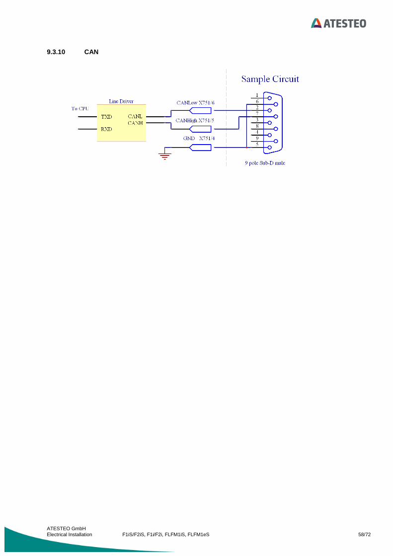
9.3.10 CAN

ATESTEO GmbH
Electrical Installation F1iS/F2iS, F1i/F2i, FLFM1iS, FLFM1eS 59/72
10 General references
10.1 Overvoltage protection
To avoid destructions the sending electronic on the rotating side will be switched off at overvoltage. The
analog output of the torque-signal shows undefined values. If this is the case, so the amplitude of the supply
voltage must be reduced. Sometimes it can happen, that the torquemeter must be turned "OFF“ for several
seconds to deactivate the overvoltage protection. All outputs are short-circuit-protected.
10.2 Torquemeter without Test Signal
In some cases it is possible, that the torque flange supports no test signal. Please refer to your calibration
sheet to see the right values.
10.3 Hotline
At any troubles, call our hotline workdays from 8:00h to 17:00h +49 (0)2404 9870-583/584
or you can reach us by email [email protected]

ATESTEO GmbH
Electrical Installation F1iS/F2iS, F1i/F2i, FLFM1iS, FLFM1eS 60/72
10.4 Flash update
A microcontroller with an internal Flash-ROM is used, so that a firmware update can easily be performed by
a special upload-software via a RS232 serial connection.
Flash update: 1. Turn off the unit (switch off power supply).
2. Connect the stator via RS232 with the PC.
3. Run the Flash-programmer software and enter settings as below.
4. Set Device Type=MB91F364 and choose by pressing the button 'Browse' the firmware file.
5. Press button 'Automatic Mode’ and turn on the converter in less than 2 seconds.
6. If the firmware is installed properly the programmer software prompts “ALL OK”.
7. Turn off the unit.
8. Turn on the unit.
The firmware update has been installed correctly.

ATESTEO GmbH
Electrical Installation F1iS/F2iS, F1i/F2i, FLFM1iS, FLFM1eS 61/72
11 Calibration of the Torquemeter
The following procedure will be recommended by means of an example.
Preparation:
The Torquemeter is mounted at the machine and without torque. The machine is blocked.
The inductive power supply must be checked. If the voltage is to low, it can be that the measuring
error becomes higher.
The connection from the lever arm to the torquemeter must be absolute planar.
Use the same screws as for the real testing.
The screws have to be screw on with the specify torque with a torque spanner.

ATESTEO GmbH
Electrical Installation F1iS/F2iS, F1i/F2i, FLFM1iS, FLFM1eS 62/72
Calibration
Pos. To do Remarks Frequency
0 Torquemeter without lever arm. Write down the zero torque
frequency
59998 Hz
1 Mount calibration lever arms. Use a balance weight to set the
frequency to frequency of
pos.0.
60000 Hz ->
59998 Hz
2 Preload torquemeter clockwise
(positive) with rated torque
Duration about 2 minutes 80000 Hz
3 Unload torquemeter
3 Mount calibration lever arms for
anticlockwise torque
4 Preload torquemeter anticlockwise
(negative) with rated torque
Duration about 2 minutes
5 Unload torquemeter
5 Mounting of the calibration lever arms
for clockwise torque
6 Load torquemeter clockwise with rated
torque
Reading of the measuring
value after one minute.
Max value P1.
P1=80000 Hz
7 Relieve torquemeter Reading of the measuring
value after one minute.
Zero value1 N1.
N1=60008 Hz
Mounting of the calibration lever arms
for anticlockwise torque.
Set the frequency to N1 with
the balance weight.
60008 Hz
8 Load torquemeter anticlockwise
(negative) with rated torque
Reading of the measuring
value after one minute.
Min value P2
P2=40000 Hz
9 Relieve torquemeter Reading of the measuring
value after one minute.
Zero value1 N2
N2=59992 Hz
Mounting of the calibration lever arms
for clockwise torque.
Calculate the zero torque to
calculate the sensitivity and the
error curve
N0 = (N1+N2)/2
N0=60000 Hz

ATESTEO GmbH
Electrical Installation F1iS/F2iS, F1i/F2i, FLFM1iS, FLFM1eS 63/72
With that the adjustment is finished and the sensitivity values can be calculated.
Zero point
2
120
NNN
; 60000
2
59992600080
HzHzN
Sensitivity1 (positive)
Mdnenn
NPS
011
;
Nm
Hz
Nm
HzHzS 000.20
1000
60000800001
Sensitivity2 (negative)
Mdnenn
NPS
021
;
Nm
Hz
Nm
HzHzS 000.20
1000
60000400001
The torquemeter has to be setup with the new sensitivity values.
Calibration Torquemeter (example rated Torque 1000 Nm)
-1500
-1000
-500
0
500
1000
1500
1 2 3 4 5 6 7 8 9 10 11 12 13 14 15 16 17 18 19 20 21 22 23 24 25 26 27 28 29
Dre
hm
om
en
t/N
m
Drehmoment
Nullpunkt1 N1
Nullpunkt2 N2
Minwert P2
Maxwert P1

ATESTEO GmbH
Electrical Installation F1iS/F2iS, F1i/F2i, FLFM1iS, FLFM1eS 64/72
With the help of the following procedure the error graph will be determined and the calibration will be
checked.
Calibration Torquemeter (example rated Torque 1000 Nm)
-1500
-1000
-500
0
500
1000
1500
1 2 3 4 5 6 7 8 9 10 11 12 13 14 15 16 17 18 19 20 21 22 23 24 25 26 27 28 29
Dre
hm
om
en
t/N
m
Drehmoment
Nullpunkt1 N1
Nullpunkt2 N2
Minwert P2
Maxwert P1

ATESTEO GmbH
Electrical Installation F1iS/F2iS, F1i/F2i, FLFM1iS, FLFM1eS 65/72
Pos. To do Remarks Frequency/Hz Torque /Nm
Check out, that position 1-9 is
done
Set the zero point with
the help of the balance
weight. (From Pos.09)
69992 -0,4
10 Load torque clockwise =
200Nm
(rated torque/ 5)
Read of the value after
one minute
63991 199,55
11 Load torque clockwise =
400Nm
(rated torque/ 5)
Read of the value after
one minute
67992 399,6
12 –
19
Load torque clockwise
600 Nm
800 Nm
1000 Nm
800 Nm
600 Nm
400 Nm
200 Nm
0 Nm
Read of after every
one minute
71994
75997
80000
76003
72004
68007
64008
60008
599,7
799,85
1000
800,15
600,2
400,35
200,4
0,4
19 Mounting of the calibration
lever arms for anticlockwise
Set the frequency to
the last value with the
balance weight.
60008 0,4
20 Load torque anticlockwise =
-200Nm
(- rated torque / 5)
Read of the value after
one minute
56008 -199,6
21 –
29
Load torque anticlockwise -
--400 Nm
-600 Nm
-800 Nm
-1000 Nm
-800 Nm
-600 Nm
-400 Nm
-200 Nm
0 Nm
Read of after every
one minute
52007
48004
44002
40000
43996
47996
51993
55992
59991
-399,65
-599,82
-799,9
-1000
-800,2
-600,2
-400,35
-200,4
-0,45

ATESTEO GmbH
Electrical Installation F1iS/F2iS, F1i/F2i, FLFM1iS, FLFM1eS 66/72
The result is the following error graph:
This error graph is the linearity/ hysteresis graph of the torquemeter.
In this example it is a torquemeter with an accuracy class of 0, 05.
Hysteresis tips
The hysteresis is a typical material property. Older torquemeter have better hysteresis characteristics than
the newer ones. The main reason for the hysteresis is a static torque. The amplitude of the hysteresis
depends on the maximum torque. If we halve the maximum torque in the example above the hysteresis will
also be halve. In this case ±0.02% of rated torque. If you use a torquemeter only clockwise or anticlockwise
the hysteresis can be neglected. For the best accuracy it is import and to inspect the read measuring task
and set the torque to zero at the right time.
Fehlerkurve
-0.1
-0.08
-0.06
-0.04
-0.02
0
0.02
0.04
0.06
0.08
0.1
-1100 -600 -100 400 900
Drehmoment / Nm
Feh
ler
/ %
v.E
.

ATESTEO GmbH
Electrical Installation F1iS/F2iS, F1i/F2i, FLFM1iS, FLFM1eS 67/72
12 Recommendations for resetting the zero point of a ATESTEO Torque measuring flange
With each measuring element, from a flexible spring element that is measured by its elastic deformation,
there will always be a zero drift even if no load is applied.
Related to DMS based Torque measuring systems, zero-drifts in a load-free condition can be caused by the
following circumstances:
12.1 Thermal influences
Despite of a complex temperature compensation a zero-drift related to high temperature fluctuations can
always be observed. Due to various temperature influences interacting permanently with the torquemeter,
another reason for exiguous zero-drifts is given.
The temperature stability defined in the technical specifications, e.g. 0.1%/10ºK is determined by the allowed
temperature drift of ±0.1% of the rated torque per 10º Kelvin difference.
12.2 Hysteresis-caused influences
If a sensor during a test is mostly loaded in one direction it can indicate a drift after the test is terminated.
This drift cannot to be traced back to a temperature compensation problem but to the natural hysteresis of
the sensor and strain gauges.
The change of the zero value depends on the torque applied or on the test duration. In any case, the value of
the zero-drift variation will not be larger than the linearity and hysteresis specified in the technical data for the
sensor.
12.3 Aging
If a strain gauge based sensor is dynamically loaded for a long period of time a zero-drift can occur. This
value depends on the cycle count and the strain amplitude. This zero-drift will affect the sensitivity of the
sensor.
Even though this is a natural effect for strain gauge sensors, ATESTEO torque sensors drift is very low due
to a low sensitivity at nominal torque.
12.4 Lateral force influence
Considering that each torque sensor is part of a powertrain, every component linked to the sensor generates
a lateral force. This load will be influenced by the size and installation of the components. This lateral force
will be added to the measuring signal. If the installation is performed as specified in the technical
specifications, this influence will be extremely small.

ATESTEO GmbH
Electrical Installation F1iS/F2iS, F1i/F2i, FLFM1iS, FLFM1eS 68/72
12.5 General
All the above mentioned items that influence the zero-drift are still in the range of calibration
tolerance, as long as the sensor is properly maintained and handled and no transportation damages
occurred to the sensor or strain gauges.
Due to the fact that all the above mentioned zero-drifts can happen in different situations at the same time it
is very difficult to suggest a general zero-reset procedure.
After considering all the information acquired through our experience and customers feedback we can
suggest and comment different scenarios for a proper zero-reset of the torque sensor.
A zero-reset is only allowed if the torque is zero.
If a great zero shift (>10 Hz) is observed during the mounting of the torquemeter please check the adapter flange due to the mechanical properties. A lower zero-shift can be reset.
The test bench engineer has to decide, whether the accuracy request of the actual test requires a reset of the zero point. Generally it is possible to improve the accuracy by resetting the zero torque after the warming-up period of the test stand and before starting the measurement.
If the zero shift is grater than 2% of the rated torque, the torquemeter must be checked. These tests (recalibration and other tests) have to be done by ATESTEO to find out the reason for the malfunction.
A zero shift of 0.05% of the rated torque per month has no influence to the accuracy of the system.

ATESTEO GmbH
Electrical Installation F1iS/F2iS, F1i/F2i, FLFM1iS, FLFM1eS 69/72
13 EC Manufacturer’s Declaration:

ATESTEO GmbH
Electrical Installation F1iS/F2iS, F1i/F2i, FLFM1iS, FLFM1eS 70/72

ATESTEO GmbH
Electrical Installation F1iS/F2iS, F1i/F2i, FLFM1iS, FLFM1eS 71/72

ATESTEO GmbH
Electrical Installation F1iS/F2iS, F1i/F2i, FLFM1iS, FLFM1eS 72/72
Sie möchten mehr über unsere Produkte, Lösungen und Services aus den Bereichen Messsysteme,
Fahrzeugausrüstung und Aktuatoren erfahren? Dann rufen Sie uns einfach an unter +49 (0) 2404 9870570
oder mailen Sie uns an [email protected]. Ihr persönlicher ATESTEO Ansprechpartner ist gern für
Sie da.
Want to learn more about our products, solutions and services in the fields of measurement systems, vehicle
equipment and actuators? Then please call us under +49 (0) 2404 9870 570 or email us at
[email protected]. Your personal ATESTEO contact is always at your disposal.
ATESTEO GmbH
Konrad-Zuse-Str. 3
52477 Alsdorf
T +49 (0) 2404 9870-0
F +49 (0) 2404 9870-59
www.atesteo.com