electric steam humidifier sk300-xl series - … · remove packing wooden crate and skids prior to...
TRANSCRIPT

Electric Steam Humidifier
SK300-XL Series
INSTALLATION INSTRUCTIONS
Read and save these instructions
SK300-XL-IOM – Rev.: 131125

SK300-XL Steam Humidifier
1
Safety
ELECTRICITY
All work concerned with electrical installation MUST only be performed by skilled and qualified technical personnel (e.g. electrician or technician with appropriate training). The customer is always responsible for ensuring the suitability of the technical personnel.
Please observe the local regulations concerning the provision of electrical installations.
HEALTH & SAFETY
NEP has considered aspects of the design of their humidification systems to reduce as far as possible the risk of Legionnaires’ disease and other similar conditions but it is important that users are also aware of their responsibilities.
To prevent the growth of Legionella, users are required to:
Avoid water temperature that favors the growth of Legionella (20-45˚C [68 to 113˚F]).
Avoid water stagnation.
Clean and disinfect the humidification system.
Have a competent person carry out a risk assessment of the water system supplying the humidifier to ensure the water supply is of an acceptable quality
CORRECT USE Neptronic® systems and products are designed only for humidification use.
Any other application is not considered use for the intended purpose. The manufacturer cannot be made liable for any damage resulting from incorrect use.
ACCESS NEVER LEAVE SK300-XL CABINET KEYS IN THE DOORS AS UNAUTHORIZED ACCESS TO LIVE ELECTRICAL PARTS MAY BE GAINED – ALWAYS STORE KEYS CENTRALLY WITH NOMINATED RESPONSIBLE PERSON.
WATER Neptronic® systems are designed to be used with mains, reverse osmosis, demineralized or partially softened water. On no account attempt to introduce any other fluid or chemical into the system without first consulting NEP or its authorized distributor.
Water supply must not exceed the max pressure of 70 psig (480 kPa), or pressure limits laid out in the Specification and Installation Instructions, and should comply with local regulations.

SK300-XL Steam Humidifier
2
Foreword Foreword
This installation and operation manual has been developed to facilitate the installation and the operation of the SK300-XL series electric steam humidifier. The strict application of these instructions will ensure the conformity of the installation and operation to the manufacturer's recommendations.
The application of these instructions is one of the conditions of the warranty.
The application of these instructions does not ensure at any time conformity with the rules in force of the country of destination.
This product has been declared to conform to applicable Canadian and American standards and bear the CSA c&us marking.
Copyright ©2013: All rights reserved, this document cannot be reproduced totally or partially by any means whether, electronic, mechanical, photocopy, recording or other, without prior written authorization of National Environmental Products Ltd.
Manufacturer Presentation
National Environmental Products Ltd (NEP) is the owner of the Neptronic® brand
NEP develops, manufactures and services a complete line of:
Electric Steam humidifiers for Residential application,
Gas fired Steam humidifiers for Commercial application,
Steam to Steam and Direct Injection Steam humidifiers for Commercial application,
Actuators to regulate air dampers or valves,
Electric heaters,
Humidistats, thermostats and other control peripherals used to control HVAC equipment,
For more information about our products, visit our web site at www.neptronic.com
Each Neptronic® product benefits from over 25 years of experience of our qualified staff. From the inspiration to realization, innovation has been the standard in design. As the result of this dedication, NEP Ltd. owns several patents, notably the Anti Foaming Electronic Controller (AFEC).
Manufacturing is conducted on the premises of our modern 7 000m2 (80,000 sq.ft) facility in Montreal, Canada.
Our quality system is built on the ISO 9001 model.
Our vision ''Customer for Life'' is realized by listening to customer needs and by supplying products, which exceed expectations in quality, functionality and durability.
National Environmental Products Ltd. Toll free in North America: 1 800 361-2308 Tel.: (1) (514) 333-1433 Fax: (1) (514) 333-3163 Customer service Fax: (514) 333-1091
Business hours: from Monday to Friday, 8:00am to 5:00pm (Eastern time)

SK300-XL Steam Humidifier
3
Table of content Safety .................................................................................................................................................... 1
Foreword ............................................................................................................................................... 2
Table of content ................................................................................................................................... 3
Technical Specifications ..................................................................................................................... 4
Dimensions & Weights ........................................................................................................................ 5
Installation Overview ........................................................................................................................... 7
Stage 1 – Unit Positioning and Mounting .......................................................................................... 8
Stage 2 – Steam Distribution Installation .......................................................................................... 9
Stage 3 – Water Supply Installation ................................................................................................. 12
Stage 4 – Water Drain Connection ................................................................................................... 13
Stage 6 –Electrical Control Connections ......................................................................................... 15
Humidity signal set-up ...................................................................................................................... 19
Initial verification & Start up ............................................................................................................. 21
Commissioning – Operation description ......................................................................................... 22
Operation display ............................................................................................................................... 23
List of alarms ...................................................................................................................................... 24
Programming mode ........................................................................................................................... 25
Wiring diagram ................................................................................................................................... 27
General conditions of sales & warranty .......................................................................................... 28

SK300-XL Steam Humidifier
4
Technical Specifications
3D opened view (Fig.1)
Model Steam cap.
(lb/h) [kg/h]
Power(kW)
Current (A) Nb of
outlets
Multi-Steam header diam.
(in) [mm] 208V /
3ph 480V /
3ph 600V /
3ph
SK330M 90
[41] 30 83.4
see standard SK300 IOM
1 3’’
[76]
SK340M 120 [56]
40 111.0 see standard SK300 IOM
1 3’’
[76]
SK370M 210 [95]
70 n/a 84 70 1 3’’
[76]
SK380M 240
[108] 80 n/a 96 81 2
3’’ [76]
SK390M 270
[122] 90 n/a 109 91 2
3’’ [76]
Notes: Maximum static duct pressure is 5” w.c. (1.25 kPa). For higher static duct pressures please consult NEP or its authorized distributor.

SK300-XL Steam Humidifier
5
Dimensions & Weights
Front view (Fig. 2)
Back view
(Fig. 3)
General Dimension & Weight
Model Dimensions in inches [mm] Weight in lb [kg]
A B C Empty Full of water
SK330M SK340M SK370M SK380M SK390M
48.1 [1221]
33 [838]
25 [635]
320 [145]
444 [200]
Water Inlet, Steam and main Drain outlets Dimensions
Model No of Steam Outlets
Dimensions in inches [mm] Steam Outlet Diam.
D E Drain OutletDiam
Water Inlet Diam
F G
SK330M SK340M SK370M
1 Ø3” [76]
18.2 [462]
n/a Ø3/4”[20]
ؽ” NPT
15.1[383]
7.5 [190]
SK380M SK390M 2 Ø3”
[76] 18.2 [462]
9 [230]
Ø3/4”[20]
ؽ” NPT
15.1[383]
7.5 [190]
Note: Drain outlet and water supply inlet are located on the right hand side of the humidifier. Left hand side location of any of is available upon request.
Electrical inlets and Pan drain outlet Dimensions
Model Dimensions in inches [mm]
Electrical KO Diam. H I J Pan Drain
Outlet Diam. K L
SK330M SK340M SK370M SK380M SK390M
Ø7/8 & 1-3/8’’ [22 & 35]
26.4 [670]
22.4 [569]
2.2 [55]
Ø1/2’’ [13]
19.2[488]
1.0 [25]
A
B
C
DE
FG
KL
H I
J
Power supply inlet
Electrical controls inlet
SK300-XL Steam Humidifier
6
Handling & Unpacking
Lifting or handling MUST only be carried out by trained and qualified personnel. Ensure that the lifting operation has been properly planned, risk assessed and that all equipment has been checked by a skilled and competent Health & Safety representative and effective control measures put in place.
It is the customer’s responsibility to ensure that operators are trained in handling heavy goods and to enforce the relevant lifting regulations.
Refer to Dimensions & Weight section for system dry weights. Handling and
Lifting The SK300-XL Steam Humidifier MUST always be handled and lifted with care and should remain in its original packaging for as long as possible prior to installation
The SK300-XL Steam Humidifier package may be carried using a forklift from the underside. Caution should be exercised to ensure balanced load before lifting.
Lifting sling angle should be greater than 30˚ to the horizontal.
Unpacking SK300-XL Steam Humidifier is shipped on a wooden crate.
Remove packing wooden crate and skids prior to installation.
List of accessories
supplied
Standard enclosure 2 sets of keys. 2 adjustable steam hose collars per
steam outlet.
The present Installation Instructions.
Wiring diagram affixed onto the interior of the electrical compartment door.
!

SK300-XL Steam Humidifier
7
Installation Overview
All installation work must comply with local regulations.
All work related to the installation of the SK300-XL Steam Humidifier MUST only be performed by skilled and qualified technical personnel (e.g. qualified gas installer, fitters, electricians, plumbers or technicians with appropriate training). The customer is responsible for ensuring their suitability.
For the installation of the SK300-XL Steam Humidifier and associated components there should be no special tooling requirements above that of a fitter’s toolkit.
Installation method statement
Stage1: Unit Positioning and Mounting
Stage 2: Steam Distribution Installation
Stage 3: Water Supply Installation
Stage 4: Water Drain Connection
Stage 5: Electrical Supply and Installation
Stage 6: Electrical Control Connections
(Fig. 4)
!
Stage 5
Stage 2
Stage 1 Watersupply
Stage 4
Stage 3
Stage 6
SK 300-XL

SK300-XL Steam Humidifier
8
Stage 1 – Unit Positioning and Mounting General
considerations
Any installation work MUST be carried out by suitably qualified personnel.
The following considerations should be taken into account before deciding on the location for the SK300-XL Steam Humidifier:
Plan a location easy to access in order to permit an easy inspection and servicing of the humidifier.
Do not install humidifier where failure of the appliance could cause damage to the building structure or to costly equipment.
Location area should be well ventilated, ambient temperature should not exceed 86˚F (30˚C).
Positioning the Humidifier
The humidifier must be installed to ensure the steam hose length is kept to the shortest possible length. For flexible steam hose: the total steam line length should not exceed 16
feet (5 meters). For longer distances use insulated hard piping. For insulated hard piping: the total steam line length should not exceed 50
feet (15 m). For longer steam line runs, consult factory. Observe the minimum access distances as shown in figure 5.
(Fig. 5) Standard enclosure
dimensions in bracket are in mm
Minimum Clearances
Minimum clearances are :
Top: 20’’(510mm) minimum Electrical panel side: 24’’ (600mm) minimum Front: 30’’ (800mm) minimum
The humidifier is designed to be installed directly on the floor. Provide a level, solid foundation for the humidifier. Ensure that the floor beneath the humidifier is water proof to withstand any water spillage during servicing or if a problem occurs. The humidifier is provided with adjustable legs in order to ensure proper level.
!
30'’ [800]
minimum
20'’ [510]minimum
24'’ [600]minimum

SK300-XL Steam Humidifier
9
Stage 2 – Steam Distribution Installation Fundamental Design
Concepts
1. Maximum steam velocity in a pipe should not exceed 40 feet/sec (12m/s) velocity. Velocities above this will generate noise.
2. Minimum steam pipe gradient should be 7˚ i.e. 5’’ (125mm) rise in 40’’ (1m) run.
3. The lowest point of any steam hose or rigid pipe must be the humidifier. A steam separator (S trap) should be installed higher than the static pressure of the system by at least 2’’ (50mm).
4. Total length of the flexible steam hose should not exceed 16 feet (5 m) or insulated rigid piping should not exceed 50 feet (15 m).
5. Whenever possible use rigid copper piping, flexible steam hose can be used for short runs or for interconnecting between rigid pipe runs, ensure that there is no kink in the flexible hose. When using rigid copper pipe, insulation should be used to diminish condensation build up.
(Fig. 6)
dimensions in bracket are in mm
(Fig. 7) dimensions in bracket are in mm
(Fig. 8)
6. Connection pipe sizes between SK300-XL and steam distributor in the duct should be 4 ¼’’ (108mm) up to 528lb/h (240kg/h)
7. All Humidifiers above 220lb/h (100kg/h) capacity should use Multi-Steam.
!
Min. 7°
Correct Installation
SK300-XL humidifierwith Multisteam.
Static pressure+ 2'’ (50)
Min. 7°
Correct InstallationSK300-XL humidifier with 2 SAMB E2 manifolds
Static pressure+ 2'’ (50)
Incorrect Installation

SK300-XL Steam Humidifier
10
Stage 2 – Steam Distribution Installation
Selection of Multi-Steam
1. For all Multi-Steam units use the Neptronic® Humidisoft program to size the unit.
2. Where two Multi-Steam units are required, duties in excess of 528lb/h (240kg/h) make your selection using the following rules:
Divide the air volume flow in half. Divide the AHU / air Duct width in half. Height of the duct must remain at 100% its height. This will size Multi-Steam units so that they can be placed side by side.
3. For installation of Multi-Steam units please refer to Neptronic® Multi-Steam Installation Instructions
Horizontal duct (Fig. 9)
dimensions in bracket are in mm
Vertical duct (Fig. 10)
dimensions in bracket are in mm
ؽ'’ (15)Static pressure+ 2'’ (50)
Min
. 50
mm
Min. 2'’ (50)
Min. 2'’ (50)
Mounting bracket must be level horizontally
Steam supply hose or
rigid pipe to Humidifier
Header must be pitched toward condensate drain
Condensate drain pipe to steam trap
Air duct
Rod, bolt, nut and
washer assembly
Static pressure+ 2'’ (50)
Min. 10º
Steam supply hose or
rigid pipe to Humidifier
Header must be pitched toward condensate drain
Air ductRod, bolt, nut and
washer assembly
Air
flow
Air
flow
SK300-XL Steam Humidifier
11
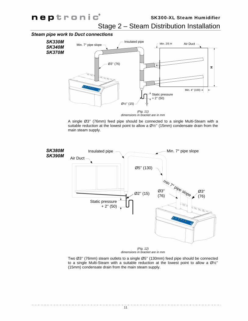
Stage 2 – Steam Distribution Installation Steam pipe work to Duct connections
SK330M SK340M SK370M
(Fig. 11)
dimensions in bracket are in mm
A single Ø3’’ (76mm) feed pipe should be connected to a single Multi-Steam with a suitable reduction at the lowest point to allow a ؽ’’ (15mm) condensate drain from the main steam supply.
SK380M SK390M
(Fig. 12)
dimensions in bracket are in mm
Two Ø3’’ (76mm) steam outlets to a single Ø5’’ (130mm) feed pipe should be connected to a single Multi-Steam with a suitable reduction at the lowest point to allow a ؽ’’ (15mm) condensate drain from the main steam supply.
Ø3'’ (76)
ؽ'’ (15)
Min. 7° pipe slope
Min. 4'’ (100)
Insulated pipe
H
Air Duct
Static pressure+ 2'’ (50)
Min. 2/5 H
min 7° pipe slopeØ3'’(76)
Ø5'’ (130)
Ø2'’ (15)
Min. 7° pipe slope
Static pressure+ 2'’ (50)
Insulated pipe
Air Duct
Ø3'’(76)

SK300-XL Steam Humidifier
12
Stage 3 – Water Supply Installation
Water supply installation should conform to local codes and regulations.
Any installation work must be carried out by suitably qualified personnel.
Water inlet Specifications
Neptronic® SK300-XL Humidifier is designed to be used with mains, reverse osmosis, de-ionized and de-mineralized water.
Maximum water supply pressure: 10 to 70psig (70 to 480kPa)
Minimum water temperature: 49˚F (+4˚C)
Maximum water temperature: 104˚F (+40˚C)
Model Wa�er inlet
Connection size SK330MSK340M SK370M SK380M SK390M
1/2’’ NPT Male
Water supply line Installation
To facilitate servicing, a shut off valve (not supplied) should be installed in the water line, within 40’’ (1m) of the humidifier.
(Fig. 13)
!
SK300-XL
Water Inlet connection
¼ turn Shut off Valve
4 ¾’’(120)
Flexible Hose
Feed Water supply line
GasketGasket

SK300-XL Steam Humidifier
13
Stage 4 – Water Drain Connection
Water Drain installation should conform to local codes and regulations.
Any installation work must be carried out by suitably qualified personnel.
Water Drain Specification
Water Drain temperature: 140˚F (+60˚C)
Model Water Drain Outlet
Connection size Pan Drain Outlet Connection size
SK330MSK340M SK370M SK380M SK390M
3/4’’ (20mm)
1/2’’ (15mm)
Water Drain Installation
Water drain outlet connection should be connected to drain pipe of sufficient size. We recommend the use of standard copper hydraulic pipes.
Minimum water drain pipe gradient should be ¼’’ (1.5mm) in 40’’ (1m) horizontal run.
No drain trap is required.
(Fig. 14)
!
SK300-XL
4 ¾’’ (120)
Ø 1½'’ (38)minimum
Ø 3/4’’ (20mm)

SK300-XL Steam Humidifier
14
Stage 5 –Electrical Supply and Installation Electrical Power
Supply The SK300-XL Steam Humidifier requires a 120, 208 or 240V single phase supply.
Model Voltage (V) Current (A)
SK330M 208 – 3ph 84
SK340M 208 – 3ph 111
SK370M 480 – 3ph 84
600 – 3ph 70
SK380M 480 – 3ph 96
600 – 3ph 81
SK390M 480 – 3ph 109
600 – 3ph 91
All incoming power supplies MUST be externally fused for over current protection.
The electrical supply should also be isolated for the purpose of emergency and servicing. A disconnect switch should typically be installed within one meter of the humidifier.
The isolator must have a contact separation of at least 1/8’’ (3mm).
Electrical connection
All work related to electrical installation MUST only be performed by skilled and qualified technical personnel (e.g. electrician or technicians with appropriate training).
Please observe local codes and regulations concerning the provision of electrical installations.
WARNING. Risk of electric Shock. Ensure that the electrical supply is isolated before beginning any installation.
WARNING: RISK OF FIRE. Do not interchanges the power terminal block designated L1, L2 and L3 with Low voltage terminal block designated 1, 2 and 3.
The installation engineer must ensure the following:
Use of copper power conductor only.
Size of the power conductors are suitable for the maximum current supplied.
Incoming power cable is secured via suitably sized cable gland.
Each terminal connection is secured firmly with a cable ferrule.
The ground conductor should be equipped with ring terminal and should be connected directly to the electrical panel on the indicated location.
Humidifier cabinet has an uninterrupted or unbroken electrical ground.
(Fig. 15)
!
L1
L3
L2
Electrical panel SK300-XL

SK300-XL Steam Humidifier
15
Stage 6 –Electrical Control Connections Humidifier Interlocks
Neptronic® SK300-XL Steam Humidifier has one interlock entry:
(Fig. 16)
High level humidistat contact should be wired in series with P.D. Switch contact and humidistat signal between terminals TB1 & 2 In case of opening of any on this contact. Operation of humidifier will stop and Alarm message will be displayed.
Humidifier Control with
humidity controller
Neptronic® SK300-XL modulating Steam Humidifier can be installed in conjunction with Neptronic® HRO and SHC humidity controller.
(Fig. 17)
5 V
dc
Low voltage control terminal block
High limit humidistat
Differential pressure switch
5 Vdc
12
2
1
345
Fuse
humidistat
24VA
C
Pressure Differentialswitch
High limit
1 432F
876 9
Control terminalblock wiring
HRO20
1614 1513
MO
D
%R
H
CO
M
SK300

SK300-XL Steam Humidifier
16
Stage 6 –Electrical Control Connections Humidifier
Control with humidity
controller and room or duct
sensor
Neptronic® SK300-XL Steam Humidifier can be controlled with Neptronic® HRO20 or HRO20 + SHR10 or SHC80 humidity sensors.
(Fig. 18)
Humidifier Control with
humidity sensors
Neptronic® SK300-XL Steam Humidifier can be installed in conjunction with Neptronic® SHR10 or SHC80 humidity sensors.
(Fig. 18)
humidistat
High limit
1 432F
876 9
Control terminalblock wiring
HRO20
SK300
24 VAC
1614
1513
12
M O D
% R H
COM
Pressure Differentialswitch
+SHR10
orSHC80
24 VAC
3 % R H
COM
%RH input
1
875
432F
6 9
1
3
2
COMMON
0-10 VDC OUTPUT
24 VAC OR VDC
SHR10or
SHC80
SK300 Humidifier
To Term. #3
To Term. #F
To Term. #6

SK300-XL Steam Humidifier
17
Stage 6 –Electrical Control Connections VAV System Neptronic® SK300-XL modulating Steam Humidifier can be installed in conjunction
with a VAV system, in this case Neptronic® SHC Duct humidity sensor will act as a Hi level Duct Humidity sensor. Humidity will be controlled by Neptronic® SHR or SHC Room or Duct humidity controller.
(Fig. 19)
Dry Contacts 2 volt free contacts are provided :
Operation (fan) contacts: One normally connected to common and one normally open contact
These contacts should be used to switch a low voltage control, up to 24Vac or Vdc, with a switching current of no more than 3 A.
(Fig. 20)
1
875
432F
6 9
SK300 Humidifier
To Term. #3
To Term. #F
To Term. #4
1
3
2
COMMON
0-10 VDC OUTPUT
24 VAC OR VDC
SHC80
1
3
2
COMMON
0-10 VDC OUTPUT
24 VAC OR VDC
SHR10or
SHC80
To Term. #F
To Term. #3
To Term. #6
Note: when SHC80 is used as Hi limitDuct sensor, control signal jumpershould be placed on 0-10 Vdc onModulating PCB (see section 8.2.4 ofinstallation instructions)
1
875
432F
6 9
Common
Normally Open
Normally Closed

SK300-XL Steam Humidifier
18
Stage 6 –Electrical Control Connections Controls
placement Typical humidifier control system should include along with the humidifier: A wall or return duct humidistat A high limit duct humidistat, An air proving switch. Placement of these devices is critical to proper operation of the overall system. The return duct humidistat must always be located before any outside air intake,
in order to ensure accurate sensing of the air from the humidified space. Alternatively a room humidistat can be used. The room humidistat should be
located on an inside wall or column. It should not be be near any discharge air from supply ducts or sources of heat or cold.
The airflow switch must be positioned to accurately open on a loss of air flow, to prevent the humidifier from running when there is no air to absorb humidity.
The high limit humidistat must be positioned far enough - 6’ minimum (1.8m) - downstream of the steam dispersion manifold(s) to prevent it from getting wet, but still allows it to accurately prevent over humidification of the duct that could result in condensation.
(Fig. 19)
Return SHC80Humidity sensor
air
air
air air
Or room HRO20humidistat
High limit humidistat
High limit SHC80 forVAV application only
6' minimum(1.8m)
Air flow switch
Steam dispersionmanifold

SK300-XL Steam Humidifier
19
Humidity signal set-up Terminal Block Modulating Printed Circuit Board
Humidity signal 0-10 Vdc
(Illus. 37)
(Illus. 40)
Humidity signal 2-10 Vdc
(Illus. 38)
(Illus. 41)
Humidity signal 4-20 mA
(Illus. 39)
(Illus. 42)
1
875
432F
6 9 0-10 Vcc+-
Pressure DifferentialSwitch
High limitHumidistat
5 Vdc
PC
B970819
RE
V. C
Jumper on0-10V
Extra jumper
TOP PCBMODULATING
CONTROLINPUT
HUMIDITYINPUT
4-20mA0-10V2-10V
4-20mA2-10V0-10V
1
875
432F
6 9 2-10 Vcc+-
Pressure DifferentialSwitch
High limitHumidistat
5 Vdc
PC
B970819
RE
V. C
Jumper on2-10V
Extra jumper
TOP PCBMODULATING
CONTROLINPUT
HUMIDITYINPUT
4-20mA0-10V2-10V
4-20mA2-10V0-10V
1
875
432F
6 9 4-20 mA+-
Pressure DifferentialSwitch
High limitHumidistat
5 Vdc
Jumpers on4-20mA & 2-10V
PC
B970819
RE
V. C
TOP PCBMODULATING
CONTROLINPUT
HUMIDITYINPUT
4-20mA0-10V2-10V
4-20mA2-10V0-10V

SK300-XL Steam Humidifier
20
Control Signal set-up Terminal Block Modulating Printed Circuit Board
Control signal 0-10 Vdc
(Illus. 43)
(Illus. 46)
Control signal 2-10 Vdc
(Illus. 44)
(Illus. 47)
Control signal 4-20 mA
(Illus. 45)
(Illus. 48)
1
875
432F
6 9
0-10 Vcc+-
Pressure DifferentialSwitch
High limitHumidistat
5 Vdc
PC
B970819
RE
V. C
Jumper on0-10V
Extra jumper
TOP PCBMODULATING
CONTROLINPUT
HUMIDITYINPUT
4-20mA0-10V2-10V
4-20mA2-10V0-10V
1
875
432F
6 9
2-10 Vcc+-
Pressure DifferentialSwitch
High limitHumidistat
5 Vdc
PC
B970819
RE
V. C
Jumper on2-10V
Extra jumper
TOP PCBMODULATING
CONTROLINPUT
HUMIDITYINPUT
4-20mA0-10V2-10V
4-20mA2-10V0-10V
1
875
432F
6 9
4-20 mA+-
Pressure DifferentialSwitch
High limitHumidistat
5 Vdc
Jumpers on4-20mA & 2-10V
PC
B970
819R
EV
. C
TOP PCBMODULATING
CONTROLINPUT
HUMIDITYINPUT
4-20mA0-10V2-10V
4-20mA2-10V0-10V
SK300-XL Steam Humidifier
21
Initial verification & Start up
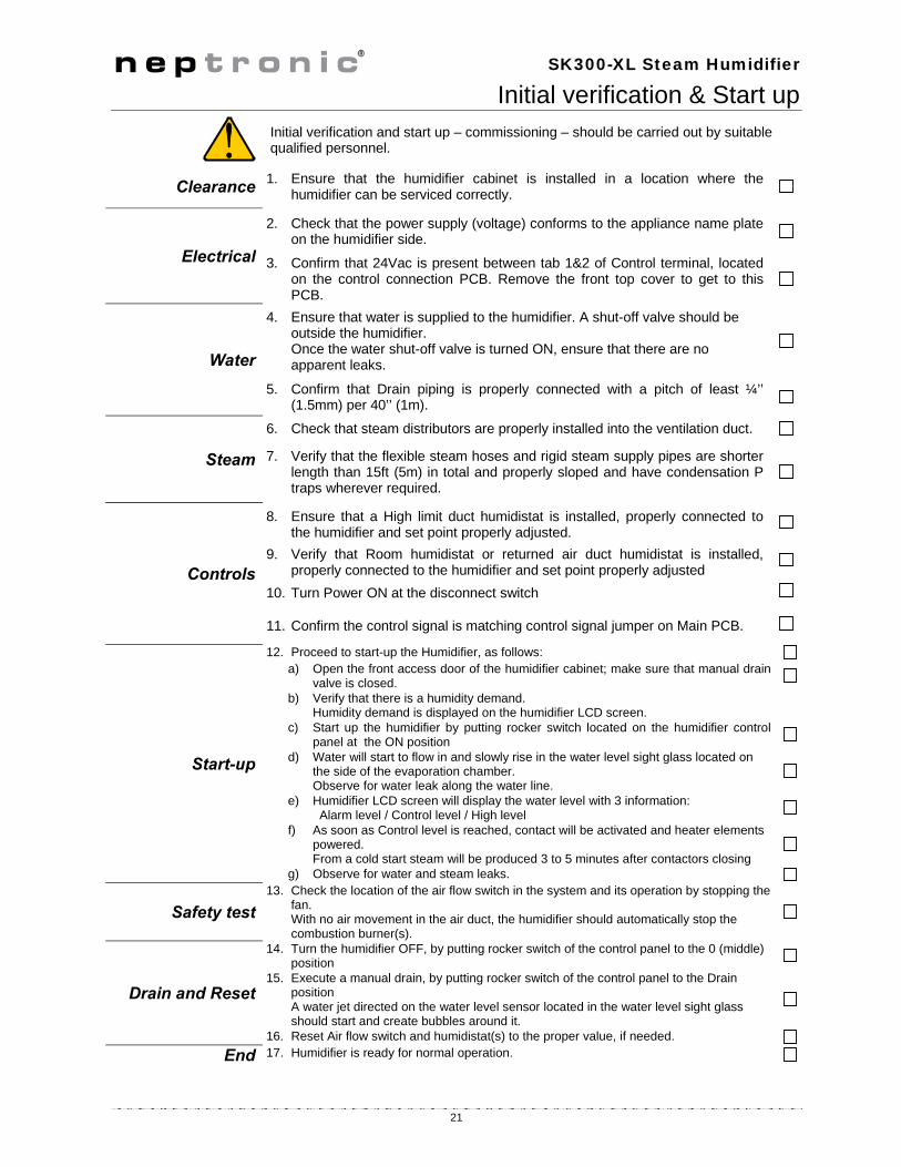
Initial verification and start up – commissioning – should be carried out by suitable qualified personnel.
Clearance 1. Ensure that the humidifier cabinet is installed in a location where the humidifier can be serviced correctly.
Electrical
2. Check that the power supply (voltage) conforms to the appliance name plate on the humidifier side.
3. Confirm that 24Vac is present between tab 1&2 of Control terminal, located on the control connection PCB. Remove the front top cover to get to this PCB.
Water
4. Ensure that water is supplied to the humidifier. A shut-off valve should be outside the humidifier. Once the water shut-off valve is turned ON, ensure that there are no apparent leaks.
5. Confirm that Drain piping is properly connected with a pitch of least ¼’’ (1.5mm) per 40’’ (1m).
Steam
6. Check that steam distributors are properly installed into the ventilation duct.
7. Verify that the flexible steam hoses and rigid steam supply pipes are shorter length than 15ft (5m) in total and properly sloped and have condensation P traps wherever required.
Controls
8. Ensure that a High limit duct humidistat is installed, properly connected to the humidifier and set point properly adjusted.
9. Verify that Room humidistat or returned air duct humidistat is installed, properly connected to the humidifier and set point properly adjusted
10. Turn Power ON at the disconnect switch
11. Confirm the control signal is matching control signal jumper on Main PCB.
Start-up
12. Proceed to start-up the Humidifier, as follows: a) Open the front access door of the humidifier cabinet; make sure that manual drain
valve is closed. b) Verify that there is a humidity demand.
Humidity demand is displayed on the humidifier LCD screen.
c) Start up the humidifier by putting rocker switch located on the humidifier control panel at the ON position
d) Water will start to flow in and slowly rise in the water level sight glass located on the side of the evaporation chamber. Observe for water leak along the water line.
e) Humidifier LCD screen will display the water level with 3 information: Alarm level / Control level / High level
f) As soon as Control level is reached, contact will be activated and heater elements powered. From a cold start steam will be produced 3 to 5 minutes after contactors closing
g) Observe for water and steam leaks.
Safety test 13. Check the location of the air flow switch in the system and its operation by stopping the
fan. With no air movement in the air duct, the humidifier should automatically stop the combustion burner(s).
Drain and Reset
14. Turn the humidifier OFF, by putting rocker switch of the control panel to the 0 (middle) position
15. Execute a manual drain, by putting rocker switch of the control panel to the Drain position A water jet directed on the water level sensor located in the water level sight glass should start and create bubbles around it.
16. Reset Air flow switch and humidistat(s) to the proper value, if needed.
End 17. Humidifier is ready for normal operation.
!

SK300-XL Steam Humidifier
22
Commissioning – Operation description Control Panel
Description Control panel of Neptronic® SK300-XL Steam humidifier is equipped with a user friendly LCD display and extensive access to status, alarms, and set-up menus.
1 Alphanumeric Display: Indicates all operation parameters and the error messages.
2
Push button , and
button gives access into program mode.
Up and Down button: Used to increase or decrease the controlled parameters of the humidifier.
3
''POWER'' indicator
O The humidifier is powered by electricity and the switch is at the AUTO position.
O The humidifier is disconnected from the power supply.
4
"CHECK" indicator
O The "CHECK" indication is normally off. It will go on as a warning against abnormal conditions of operation. For details consult the Alphanumeric Display (see section 9.1.3 Diagnostic mode).
O blinking
Maintenance is required. The Running hours have exceeded the Service hours. (see section 12 – Service).
O No abnormal conditions of operation.
5 "FILL" indicator
O Indication that the water supply (fill) valve is open.
O Indication that the water supply (fill) valve is closed.
6
"STEAM" indicator
O ON/OFF model, the STEAM indicator lights when the contactor is closed and steam is being generated.
O blinking
Modulating model, the STEAM indicator blinks ON and OFF in proportion to the percentage of steam output the humidifier is generating. (The proportion is displayed on the alphanumeric display (1)). For 100% the indicator will be lit with no blink.
O There is no steam being produced.
7
Switch "AUTO/OFF/DRAIN"
AUTO Position AUTO (I): Humidifier will generate steam based on demand from the humidistat.
OFF Position OFF (O): Humidifier will shut off.
DRAIN Position DRAIN: Humidifier will stop operating and the evaporation chamber will drain the water out. This will be done tipically at regular service.
8
Indicator "DRAIN"
O Drain valve is opened, whether as a result of an automatic drain cycle or because the front panel switch is manually set to DRAIN.
O Drain valve is closed.
SK390Rev. 3.5
12345678

SK300-XL Steam Humidifier
23
Operation display
Description display modes ''OFF'' Mode
When the rocker switch is in the ''OFF'' position, the display shows the model of the humidifier and the program version number.
(Illus. 52)
Scroll Mode
When the rocker switch is in the auto position, the display scrolls the following information every 6 seconds:
Display Description Comment
Display Space and Duct Relative Humidity readings.
Only on modulating humidifiers (suffix M). If no High limit Duct sensor is installed second line is left blank
Quantity of steam produced by the humidifier
I.e.: The actual output of the humidifier at that moment is 30 lb/hr.
A L A R ML E V E L
Low water level. Below this water level, the humidifier shuts off and the water supply valve is activated until sufficient level is reached.
C O N T R O LL E V E L
Water level is controlled The water supply valve is activated below this level.
H I G HL E V E L
Water at maximum level. The water supply valve is automatically deactivated.
NEP 3.6SK390M
RH 25%DCT 68%
lb /hr30

SK300-XL Steam Humidifier
24
List of alarms When the following conditions occur, the diagnostic messages override the scrolling information:
Display Description Comment
N OD E M A N D
No demand
Modulating humidifier: No analog signal to the humidifier. On/Off humidifier: Humidity level has exceeded the set point of the humidistat or humidity level has exceeded the set point on the high limit humidistat or airflow is not detected by the air pressure switch.
Safety open Humidity level has exceeded the set point on the high limit humidistat or airflow is not detected by the air pressure switch (modulating humidifier only).
D R A I NC Y C L E
Drain cycle The humidifier is in the automatic drain mode.
C O N T A C TD E L A Y
Contact delay 15 second delay for the power contactor to be activated.
O V E RH E A T E D
Overheated The temperature inside the container has exceeded the boiling temperature. The humidifier has automatically shut off.
P R O B ED E F E C T E D
Defected probe The water level sensor is not operational. The humidifier has automatically shut off.
N OL E V E L
No water Water has not reached the level probe
F O A M I N GC Y C L E
Drain foam AFEC (Anti Foam Energy Conservation) detects foam. The humidifier drains for a few minutes and returns to normal operation.
D R N / P R O BB L O C K
Drain or probe block The humidifier drains but the water level does not decrease, the humidifier has automatically shut off.
VerifyRH Sens
Verify RH sensor Signal from either SHR10 or SHC80 used as space sensor is lower than 0.49 Vdc to terminal # 6 of humidifier.There might be a connection problem or a defective sensor.
VerifyDCT Sens
Verify Duct sensor Signal from SHC80 used as Hi limit duct sensor is lower than 0.49 Vdc to terminal # 4 of humidifier.There might be a connection problem or a defective sensor.
SAFETYOPEN

SK300-XL Steam Humidifier
25
Programming mode To enter into programming mode, please push button at any time, to advance the program function to the next programming step in the menu push the same button twice.
Unless other instructions, you can make a selection by using & buttons on control panel.
Step Display Description Comment
01
Set point RH origin
Out: Output set point to HRO20 Int: Internal. Value : from 00 to 100% Default: Out 30%
To enable set point to humidifier display
Press the button to reach step 5, the RUNNING message will appear.
Press and hold the TEST button located on Main Pc board inside electrical compartment for 10 seconds.
Release the TEST button then press the RESET button on the same main pc board. Set point is now displayed on the humidifier display.
If Output is selected, the set point is sent from the humidifier to the humidistat HRO20. If SHR10 or SHC80 is connected with humidifier, please select Internal, this will allow you to set up RH set point directly from Humidifier. To switch between Output and Internal Set point:
Press and hold the TEST button located on Main Pc board inside electrical compartment until the change of the value.
02 optional
Set point VAV allows Hi limit Duct humidity control OFF: Duct humidity control disable. 65%: High limit Duct humidity set point value. Default: OFF
If Set point VAV is disabling, no humidity signal from the VAV Duct will be considered. If a Set point VAV value is set, the humidity output will be controlled by both space and High limit duct humidity signal. To allow Set point VAV value: Press and hold the TEST button located on Main Pc board inside electrical compartment until OFF is disappeared. You can then select the VAV Set point value desired by
using & buttons on control panel. Note: This Step will appear only if Internal has been selected at step 01
03 optional
Prop Band allows the set up of proportional band. From 3 to 9% Default: 3%
Proportional band can be set from 3% to 9% of the humidity set points values (Space and High limit duct).
Select the appropriate value by using & buttons on control panel. Note: This Step will appear only if Internal has been selected at step 01
04 D R A I N8 H R S
Drain frequency. From 1 to 24 hours Default: 4 Hrs
Choose the initiation of a drain cycle for 1 to 24 hours. In general, harder the water is, more often the drain cycle should be. Drain cycle setting does not affect the AFEC system.
05 R U N N I N G0 6 4 5 H R S
Number of running hours Information only, no possible set up.
The humidifier has operated 645 hours since the last service.
After service, press simultaneously & buttons for 15 seconds to reset the number of hours of operation to zero. This procedure will stop the CHECK indicator from flashing.
06 S E R V I C E1 0 0 0 H R S
Hour span between servicing. From 400 to 1500 hours. Default: 1000 Hrs
You can set the number of hours of operation before the humidifier will call for service (blinking of CHECK light every 4 seconds) from 400 to 1500 hours. In general, harder the water is, lower the number of hours of operation before service should be.
07 L O C K O N8 0 % P W R
Output Span. From 00 to 100%. Default: 100%
This option is available only on modulating model. i.e.: In this case, the humidifier will deliver 80% of its maximum rated output when at full demand.
Note: Any changes made in the Program Mode are saved into a non-volatile memory.
When the humidifier is anywhere in the Menu Driven Program Mode, the normal operation of the humidifier is halted.
To resume normal operation, exit the menu program mode by pressing the button until the alphanumeric display is clear. (This happens after step 7)
SETPOINTOUT 30%
SETPOINTVAV OFF
PROPBAND3%

SK300-XL Steam Humidifier
26
Control PC Board Main Printed circuit board designated is common to all SK300-XL series humidifier, ON/OFF or modulating; this pc board is equipped with an advanced microprocessor which controls all the humidifier functions. The Printed circuit board which is directly connected onto the main pc board is installed only on modulating model (suffix M). Staging PC Board (HEC002SK) is controlling the 2 on/off stages (Contactor 2 and Contator3)
Main p.c. board There are 3 water level L.E.D.’s in the upper right hand
side. They indicate the relative water height as sensed by the water level sensor. o If HI is illuminated: water supply valve shuts off, o If LO is off: An evaporation chamber filling is ordered,
water supply valve opens. o If LA is off: No water is detected by the water level
sensor, the power to the elements is shot off. The 3 status L.E.D.’s at the center left side operate as
follows: o FILL indicates that the water supply valve is feeding
water. o DRAIN indicates the drain valve empties the
container. o CONT indicates that power is supplied to the
elements and the humidifier is producing steam. TEST button should be used when commissioning the
humidifier; this will initiate a pre-programmed start-up cycle. The start up cycle cleans the supply water and the evaporation chamber (see section 11 – start-up). This button enable also the set point control of the humidistat to humidifier display (see section 9.2 –Programming) (this is available only on Modulating model).
RESET button enable the bypass of start up sequence.
(Illus. 53)
Modulating p.c. board The 3 jumpers at the center of the p.c. board (Control Input) are used for proper selection of the incoming
control signal. See section Control signal set-up The 3 jumpers at the bottom of the p.c. board (Humidity Input) are used for proper selection of the
incoming humidity signal. See section Humidity signal set up.
Staging p.c. board This PCB does not require any set-up, it is connected to the contactor 2 and contactor 3 controlling the 2 on/off stages.
PC
B970819
RE
V. C
TOP PCBMODULATING
CONTROLINPUT
HUMIDITYINPUT
4-20mA0-10V2-10V
4-20mA2-10V0-10V

SK300-XL Steam Humidifier
27
Wiring diagram
Heatingelement
PC
B9
7081
9R
EV
. C
Display terminalFlat cable to display PCB
AUTO
OFF
DRAIN
FILLDRAIN
STEAM
CHECKPOWER ON
High temp limit switch(Klixon)
Drain pump
Fill valve #1
Level sensor
Level sensor PCB
L1 L3 4321F 6
Terminal connection
SSR
Heating element
4-20 mA2-10 Vdc0-10 Vdc
No 3 - 4-20 mAcommoncommon
No 4 + 4-20 mA2-10 Vdc0-10 Vdc
No 6 RH%
Red
Red
Gre
en
Bla
ck
Bla
ck
Bla
ck
Gre
en
Grey
Red
Mar
ine
Black
Black
BlackBlack
Red
Red
Blue
BlueYellow
Red
PurpleBlackWhite
Orange
RedMarineYellow
Brown
Red
Purple
Pur
ple
Mar
ine
Red
Mar
ine
Control Signal
Whi
teB
lack
Ora
nge
Pur
ple
Purple
Purple
Blu
e
Black
BlackContactor stage 1
Rocker switch
Modulating PCB
To high limit switch and differential pressure switch No 1 & 2
No F 24 Vac Input for modulating control(s)
Fuse
Con
trol
Pan
el
LED
Red
Purple
Purple
Red
7 8 9
Wh
ite
Bla
ck
Ora
nge
No 7 Alarm Normally close
No 8 Alarm Normally open
No 9 Alarm common
Whi
te
L2
Transformer
24 Vac
TOP PCBMODULATING
CONTROLINPUT
HUMIDITYINPUT
4-20mA0-10V2-10V
4-20mA2-10V0-10V
Black
Black
Black
Black
Purple
Black
Black
Red
Fill valve #2
Brown
X-10
0
INP
UT
CO
M
AC
IN
A16 A17 A19A18
GN
D2
4 VA
CC
OM
Relay
Q1
NW
HE
C0
02SK
Q2
-SS
R+
SS
R
Black
Purple
Black
Black
Contactor stage 3
Contactor stage 2
Red
Red
Black
Black
Black
Yellow
Marine
Marine
Purple
Red
Red
Red
Red
Purple
Heatingelement
7
89
4
56
31
2
Fuses
Fuses
Fuses

SK300-XL Steam Humidifier
28
General conditions of sales & warranty
1. General
Unless otherwise arranged, in writing, the acceptance of the Order Confirmation by the purchaser includes acceptance of the "General Conditions of Sale and Warranty" of National Environmental Products, Ltd hereafter referred to as NEP.
2. Incoterms The international rules for interpretation of trade terms "Incoterms" as defined by the ICC Incoterms publication no. 460 from 1990, shall apply to the commercial terms used herein.
3. Confirmation of Order NEP shall not be deemed to have accepted an order until written "Order Confirmation" from NEP is issued to the purchaser. It is the responsibility of the purchaser to verify that all information concerning his/her order is correct and to notify NEP In writing, of any discrepancy prior to the order being shipped. In the event of a change or correction to an existing order, a second "Order Confirmation" will be issued by NEP.
4. Price Our prices are net, Ex-works Montreal in U.S. Currency, unless stated otherwise. Minimum orders shall be $50.00 minimum. Shipping and Handling charges are $5.00 minimum per order unless the shipment is billed to the purchaser's account or shipped freight collect. NEP reserves the right to adjust accepted prices in the event of alterations in rates of exchange, variations in costs of materials, changes in wages, interference on the part of the Government or similar conditions over which NEP has no control.
5. Payments terms Major credit cards, C.O.D., Prepayment. For open account, invoices are payable within 30 days from the date of invoice without no deduction, unless specify otherwise. An interest charge of 2% per month will be included on all overdue payments. No new order will be process if invoices are not paid within 45 days.
6. Transfer of ownership The goods shall remain the property of NEP until the full payment for the goods has been received by NEP.
7. Delivery terms Shipments are Ex-works 400 Lebeau, Montreal, Quebec, H4N 1R6, CANADA unless notified otherwise. Unless special instructions, the order will be delivery in the way which NEP deems best without guaranteeing this to be the cheapest way of transport. For International Order, a written designation naming the freight forwarding agent is required and will remain in effect until notified otherwise. Any discrepancy, damage or breakage should be reported in writing both to NEP and to the Carrier within 5 working days from the receipt date.
8. Risk From the moment of delivery, the purchaser shall bear all risks for the goods and NEP shall not be responsible for loss and damage incurred during transportation.
9. Delivery time Delivery time is stated approximately and depends on the product ordered, please allow a minimum of:
2 weeks for processing North American order. 6 weeks for processing International order.
We will make every effort to adhere to our delivery promises, but will not accept order or contract cancellation or any liability for any direct or indirect losses that may arise for any reason whatsoever as a result of our failure to adhere to such promises.
10. Return of good
Goods received by the purchaser cannot be returned unless a completed "R.M.A. Form" (Return Material Authorization Form) has been issued by NEP's Customer Service. Any returned goods must be sent to NEP 400 Lebeau, Montreal, Quebec, H4N 1R6, CANADA, unless stated otherwise by the R.M.A. Form, accompanied with the completed "R.M.A. Form", the R.M.A. number shall be prominently displayed on the shipping box. Unauthorized returns will be refused. Any returned goods must be sent freight prepaid. Any goods that come to us freight collect will be refused and returned to sender unless previously agreed to by us in writing on the "R.M.A. Form". Goods returned for credit shall be in condition for resale in the original box and properly packaged. Units, accessories or components that have been installed are not returnable and not refundable. Credit is subject to an overhead charge of 30% of the invoice plus shipping & handling if returned within 30 days of the invoice date and 50% from 30 to 60 days. Credit may only be applied against existing or future purchases. Non standard product (SK units with special feature), Multisteam manifolds and any DI unit are not returnable and not refundable.
11. Warranty Provided that the terms of payment are observed, the purchaser is offered a warranty of 24 months from the original purchase date of delivery for any NEP's standard product, provided the equipment has been properly installed and operated in accordance with NEP instructions. The warranty covers faulty manufacture, design and/or defective materials and is limited to the equipment and components. The warranty shall cease to be valid in the event of misapplication, incorrect installation, improper maintenance or any other incorrect uses or misuse of the product. For the SK series, the warranty furthermore ceases to be valid if the user disconnects or removes any electronic or mechanical components prior disconnecting the input power. NEP assumes no responsibility for repairs made on equipment, unless performed by NEP's authorized personnel. The defective product or component shall be returned in accordance with the paragraph 10 (Returns of goods) as described in this document. NEP agrees under the warranty to repair or replace (at the discretion of NEP) such standard product or component, which upon examination by NEP are found to be defective. Product or component replaced or repaired under warranty will be sent back to the purchaser, standard freight paid by NEP Expenses in connection with travelling time, dismantling and mounting shall not be paid by NEP Guarantee for products or components sold but not manufactured by NEP, is only given to the same extent as given to NEP, however, not exceeding the normal NEP warranty. Parts used for repairs are warranted for the balance of the term of the warranty on the original humidifier or 90 days, whichever is longer. Any repair made, after the original warranty period; at the NEP facilities are warranted for 1 month from the date of repair.
12. Proper law and jurisdiction This contract is and shall be deemed to have been made in the province of Quebec, CANADA, and shall in all respects, be governed by the province of Quebec laws.

Neptronic®
Head office: 400 Blvd Lebeau, Montreal, Qc, H4N 1R6, CANADA Tel.: (1) 514 333-1433 Fax: (1) 514 333-3163 Customer service Fax: (1) 514 333-1091
Toll free: 1 800 361-2308
Business hours: from Monday to Friday, 8:00am to 5:00pm (Eastern Time)
Toll free US: 1 800 883-7943
www.neptronic.com ©2013