electric motors and generators chapter 23
TRANSCRIPT

Storey: Electrical & Electronic Systems © Pearson Education Limited 2004 OHT 23.‹#›
Electric Motors and Generators
▪ Introduction
▪ A Simple AC Generator
▪ A Simple DC Generator
▪ DC Generators or Dynamos
▪ AC Generators or Alternators
▪ DC Motors
▪ AC Motors
▪ Universal Motors
▪ Electrical Machines – A Summary
Chapter 23

Storey: Electrical & Electronic Systems © Pearson Education Limited 2004 OHT 23.‹#›
Introduction
▪ In this lecture we consider various forms of rotating
electrical machines
▪ These can be divided into:
– generators – which convert mechanical energy into
electrical energy
– motors – which convert electrical energy into
mechanical energy
▪ Both types operate through the interaction between a
magnetic field and a set of windings
23.1

Storey: Electrical & Electronic Systems © Pearson Education Limited 2004 OHT 23.‹#›
A Simple AC Generator
▪ We noted earlier that Faraday’s law dictates that if a
coil of N turns experiences a change in magnetic
flux, then the induced voltage V is given by
▪ If a coil of area A rotates with respect to a field B,
and if at a particular time it is at an angle to the
field, then the flux linking the coil is BAcos, and the
rate of change of flux is given by
23.2
t
ΦNV
d
d=
( )
coscos
d
d
d
sind===
ttBA
dt
dΦ

Storey: Electrical & Electronic Systems © Pearson Education Limited 2004 OHT 23.‹#›
▪ Thus for the arrangement shown below
t
ΦNV
d
d=
( )
cos
d
sind
d
dNBA
tNBA
t
ΦNV ===

Storey: Electrical & Electronic Systems © Pearson Education Limited 2004 OHT 23.‹#›
▪ Therefore this arrangement produces a sinusoidal
output as shown below

Storey: Electrical & Electronic Systems © Pearson Education Limited 2004 OHT 23.‹#›
▪ Wires connected to
the rotating coil
would get twisted
▪ Therefore we use
circular slip rings
with sliding
contacts called
brushes

Storey: Electrical & Electronic Systems © Pearson Education Limited 2004 OHT 23.‹#›
A Simple DC Generator
▪ The alternating signal from the earlier AC generator
could be converted to DC using a rectifier
▪ A more efficient approach is to replace the two slip
rings with a single split slip ring called a commutator
– this is arranged so that connections to the coil are
reversed as the voltage from the coil changes polarity
– hence the voltage across the brushes is of a single
polarity
– adding additional coils produces a more constant output
23.3

Storey: Electrical & Electronic Systems © Pearson Education Limited 2004 OHT 23.‹#›
▪ Use of a commutator

Storey: Electrical & Electronic Systems © Pearson Education Limited 2004 OHT 23.‹#›
▪ A simple generator with two coils

Storey: Electrical & Electronic Systems © Pearson Education Limited 2004 OHT 23.‹#›
▪ The ripple can be further reduced by the use of a
cylindrical iron core and by shaping the pole pieces
– this produces an
approximately
uniform field in the
narrow air gap
– the arrangement
of coils and core
is known as the
armature

Storey: Electrical & Electronic Systems © Pearson Education Limited 2004 OHT 23.‹#›
DC Generators or Dynamos
▪ Practical DC generators or dynamos can take a
number of forms depending on how the magnetic
field is produced
– can use a permanent magnet
– more often it is generated electrically using field coils
▪ current in the field coils can come from an external supply
– this is known as a separately excited generator
▪ but usually the field coils are driven from the generator output
– this is called a self-excited generator
– often use multiple poles held in place by a steel tube
called the stator
23.4

Storey: Electrical & Electronic Systems © Pearson Education Limited 2004 OHT 23.‹#›
▪ A four-pole DC generator
Storey: Electrical & Electronic Systems © Pearson Education Limited 2004 OHT 23.‹#›
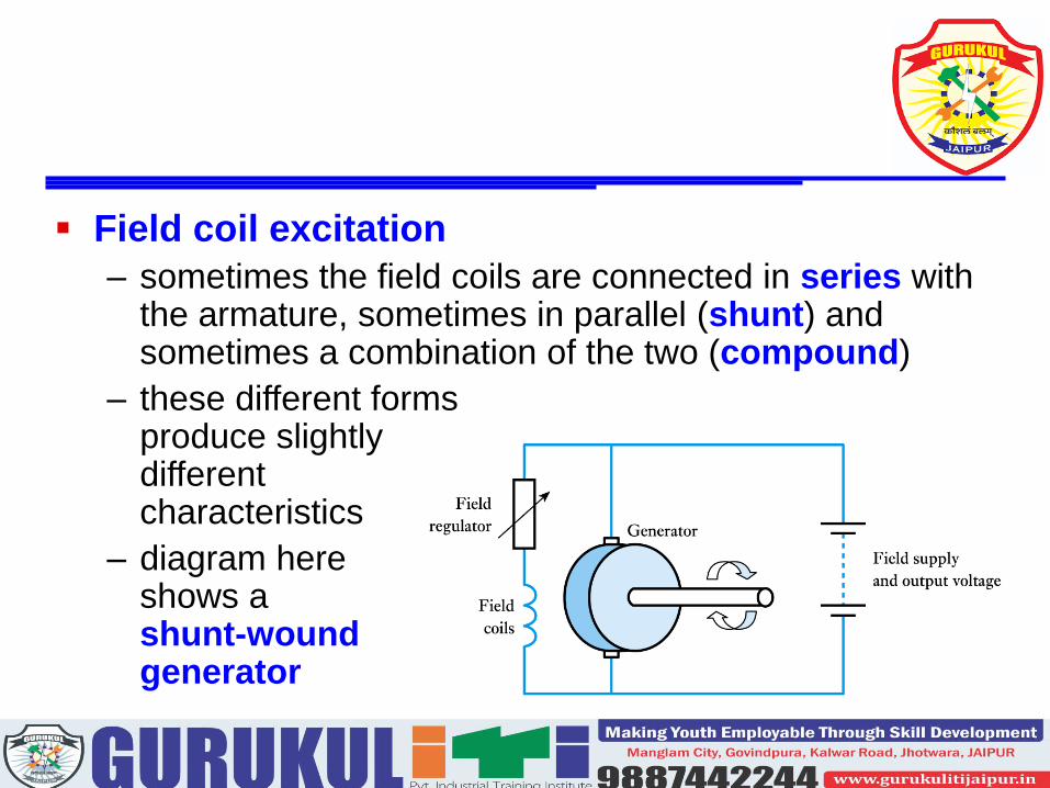
▪ Field coil excitation
– sometimes the field coils are connected in series with the armature, sometimes in parallel (shunt) and sometimes a combination of the two (compound)
– these different formsproduce slightlydifferentcharacteristics
– diagram hereshows ashunt-woundgenerator

Storey: Electrical & Electronic Systems © Pearson Education Limited 2004 OHT 23.‹#›
▪ DC generator characteristics
– vary slightly between forms
– examples shown here are for a shunt-wound generator

Storey: Electrical & Electronic Systems © Pearson Education Limited 2004 OHT 23.‹#›
AC Generators or Alternators
▪ Alternators do not require commutation
– this allows a simpler construction
– the field coils are made to rotate while the armature
windings are stationary
▪ Note: the armature windings are those that produce the output
– thus the large heavy armature windings are in the
stator
– the lighter field coils are mounted on the rotor and
direct current is fed to these by a set of slip rings
23.5

Storey: Electrical & Electronic Systems © Pearson Education Limited 2004 OHT 23.‹#›
▪ A four-pole alternator

Storey: Electrical & Electronic Systems © Pearson Education Limited 2004 OHT 23.‹#›
▪ As with DC generators multiple poles and sets of windings are used to improve efficiency
– sometimes three sets of armature windingsare spaced 120 apart around the stator to forma three-phase generator
▪ The e.m.f. produced is in sync with rotation of the rotor so this is a synchronous generator
– if the generator has a single set of poles the output frequency is equal to the rotation frequency
– if additional pole-pairs are used the frequency is increased accordingly

Storey: Electrical & Electronic Systems © Pearson Education Limited 2004 OHT 23.‹#›
Example – see Example 23.2 from course text
A four-pole alternator is required to operate at 60 Hz. What is the required rotation speed?
A four-pole alternator has two pole pairs. Therefore the output frequency is twice the rotation speed. Therefore to operate at 60Hz, the required speed must be 60/2 = 30Hz. This is equivalent to 30 60 = 1800 rpm.

Storey: Electrical & Electronic Systems © Pearson Education Limited 2004 OHT 23.‹#›
DC Motors
▪ When current flows in a conductor it produces a
magnetic field about it - as shown in (a) below
– when the current-carrying conductor is within an
externally generated magnetic field, the fields interact
and a force is exerted on the conductor - as in (b)
23.6

Storey: Electrical & Electronic Systems © Pearson Education Limited 2004 OHT 23.‹#›
▪ Therefore if a conductor lies within a magnetic field:
– motion of the conductor produces an electric current
– an electric current in the conductor will generate motion
▪ The reciprocal nature of this relationship means that,
for example, the DC generator above will function as a
DC motor
– although machines designed as motors are more
efficient in this role
▪ Thus the four-pole DC generator shown earlier could
equally well be a four-pole DC motor

Storey: Electrical & Electronic Systems © Pearson Education Limited 2004 OHT 23.‹#›
▪ DC motor characteristics
– many forms – each with slightly different characteristics
– again can be permanent magnet, or series-wound,
shunt-wound or compound wound
– figure below shows a shunt-wound DC motor

Storey: Electrical & Electronic Systems © Pearson Education Limited 2004 OHT 23.‹#›
AC Motors
▪ AC motors can be divided into two main forms:
– synchronous motors
– induction motors
▪ High-power versions of either type invariably operate
from a three-phase supply, but single-phase
versions of each are also widely used – particularly
in a domestic setting
23.7

Storey: Electrical & Electronic Systems © Pearson Education Limited 2004 OHT 23.‹#›
▪ Synchronous motors
– just as a DC generator can be used as a DC motor, so
AC generators (or alternators) can be used as
synchronous AC motors
– three phase motors use three sets of stator coils
▪ the rotating magnetic field drags the rotor around with it
– single phase motors require some starting mechanism
– torque is only produced when the rotor is in sync with
the rotating magnetic field
▪ not self-starting – may be configured as an induction motor
until its gets up to speed, then becomes a synchronous motor

Storey: Electrical & Electronic Systems © Pearson Education Limited 2004 OHT 23.‹#›
▪ Induction motors
– these are perhaps the most important form of AC motor
– rather than use slip rings to pass current to the field
coils in the rotor, current is induced in the rotor by
transformer action
– the stator is similar to that in a synchronous motor
– the rotor is simply a set of parallel conductors shorted
together at either end by two conducting rings

Storey: Electrical & Electronic Systems © Pearson Education Limited 2004 OHT 23.‹#›
▪ A squirrel-cage induction motor

Storey: Electrical & Electronic Systems © Pearson Education Limited 2004 OHT 23.‹#›
▪ In a three-phase induction motor the three phases produce a rotating magnetic field (as in a three-phase synchronous motor)
– a stationary conductor will see a varying magnetic field and this will induce a current
– current is induced in the field coils in the same way that current is induced in the secondary of a transformer
– this current turns the rotor into an electromagnet which is dragged around by the rotating magnetic field
– the rotor always goes slightly slower than the magnetic field – this is the slip of the motor
Storey: Electrical & Electronic Systems © Pearson Education Limited 2004 OHT 23.‹#›
▪ In single-phase induction motors other techniques
must be used to produce the rotating magnetic field
– various techniques are used leading to various forms
of motor such as
▪ capacitor motors
▪ shaded-pole motors
– such motors are inexpensive and are widely used in
domestic applications

Storey: Electrical & Electronic Systems © Pearson Education Limited 2004 OHT 23.‹#›
Universal Motors
▪ While most motors operate from either AC or DC,
some can operate from either
▪ These are universal motors and resemble series-
wound DC motors, but are designed for both AC and
DC operation
– typically operate at high speed (usually > 10,000 rpm)
– offer high power-to-weight ratio
– ideal for portable equipment such as hand drills and
vacuum cleaners
23.8

Storey: Electrical & Electronic Systems © Pearson Education Limited 2004 OHT 23.‹#›
Electrical Machines – A Summary
▪ Power generation is dominated by AC machines
– range from automotive alternators to the synchronous
generators used in power stations
– efficiency increases with size (up to 98%)
▪ Both DC and AC motors are used
– high-power motors are usually AC, three-phase
– domestic applications often use single-phase induction
motors
– DC motors are useful in control applications
23.9

Storey: Electrical & Electronic Systems © Pearson Education Limited 2004 OHT 23.‹#›
Key Points
▪ Electrical machines include both generators and motors
▪ Motors can usually function as generators, and vice versa
▪ Electrical machines can be divided into AC and DC forms
▪ The rotation of a coil in a uniform magnetic field produces a sinusoidal e.m.f. This is the basis of an AC generator
▪ A commutator can be used to produce a DC generator
▪ The magnetic field in an electrical machine is normally produced electrically using field coils
▪ DC motors are often similar in form to DC generators
▪ Some forms of AC generator can also be used as motors
▪ The most widely used form of AC motor is the induction motor