electric actuators · sluggish performance of pneumatic actuators or the unreliability of typical...
TRANSCRIPT

ELECTRIC ACTUATORS
HAR
OLD
BECK
.CO
M
DSG-200
MADE IN THE USA
SINCE 1936
AN ISO 9001 COMPANY
IMPROVING INDUSTRIAL CONTROL SINCE 1936

THE HISTORY OFM A K I N G B E C K A C T U A T O R S
Since 1936
1936
1936 - 1942
Where it all began. Harold
Hill basement.
Later that same year, a bigger basement became necessary. The
W. Mt Airy Ave, Philadelphia, PA.
1942

1970 - Present
1945
Newtown, PA.
And yet more space was
T O D A Y
S T I L L S E R V I N G I N D U S T R YStill Made in the U.S.A.
4

5
TABLE OF CONTENTSIntroduction ............................................................................................... 7 Process Control Improvement .........................................................................................8
Rotary ActuatorsAvailable in a range of torque outputs from 15 to 8,000 lb-ft. Linkage kits, pedestals and valve hardware are available for easy field mounting to final control elements.
Model Group 11 ................................................................................................................ 11 Damper and quarter-turn valve actuators Model Group 22 ................................................................................................................25 High torque damper actuators Model Group 31 ................................................................................................................33 Compact actuators for low torque damper and valve applications Model Group 57 ................................................................................................................41 AC/DC powered quarter-turn valve actuators Model Group 75 ................................................................................................................47 Special purpose actuators for windbox dampers and small valve applications
where heat, space and access is an issue.
Linear ActuatorsAvailable with a range of stroke options from 5/16" to 18", custom hardware is available for easy field mounting to final control elements.
Model Group 14 ................................................................................................................57 Providing up to 4,000 lbs. of thrust, these actuators incorporate a unique
design feature that ensures tight shut-off at the end of travel—commonly used on globe valve applications
Model Group 29 ................................................................................................................65 Providing up to 6,100 lbs. of thrust, these actuators incorporate a unique
design feature that ensures tight shut-off at the end of travel—even in hazardous locations
Model Group 42 ................................................................................................................73 Long stroke actuators providing up to 1,000 lbs. of thrust, ideally suited for
burner air register type applications
Specialty Applications ............................................................................. 82Beck electric actuators are available to improve the efficiency of almost any process; including multi-rev drives, burner tilt units, fluid couplings, magnetic couplings, material flow gates and pump handle valves.
Accessories / Services ............................................................................ 84Beck offers a wide range of accessories and services to meet all of your actuation needs; including installation assistance, various options, linkage kits, hazardous location ratings, site surveys and spare parts planning. Beck also offers remotely located electronics for extreme application sites, remote indication and/or control stations and a back-up power option.

6

7
INTRODUCTIONBeck's reliability, unique design and expert assistance will help you meet your process control objectives.
INDUSTRY’S CHOICE FOR PRODUCT AND SERVICE EXCELLENCE
Uniquely designed Beck electric actuators offer constant, precise control without the performance and maintenance limitations of typical actuators. Unlike pneumatic and conventional electric actuators, Beck actuators can withstand continuous duty modulation without degradation of performance. Our unique electric actuators combine the positioning necessary for optimum control with the reliability to keep the process running. • Unique, no-burnout motor allows continuous
modulation • Easy drop-in installation • Factory calibrated smart digital control
electronics • Virtually maintenance-free • Three year warranty Beck has an electric actuator for most industrial control applications and, with over 80 years of industrial actuation experience, we have the know-how to ensure an excellent solution to your actuator needs.
Industries Served Beck actuators provide precise, reliable positioning of valves, dampers, fluid couplings and other final control elements. Below is a list of just some of the industries that depend on Beck actuators: • Wood products • Electric power • Cement and lime • Pulp and paper • Water and wastewater treatment • Glass • Minerals • Chemical/petrochemical • Steel • Refineries • Aluminum and other metals • Food and beverage For more detailed information regarding our industrial applications, visit our website: http://www.haroldbeck.com/industries.htm
ScanforVideo

8
PROCESS CONTROL IMPROVEMENTEngineered to the High Performance Standards of Today’s Sophisticated Control Instrumentation To fully utilize the power and performance capabilit ies of today’s process control instrumentation, the final control element must be positioned quickly, precisely and consistently. Beck electric actuators provide instantaneous response with the precision and repeatability necessary to fully utilize control system capabilities. As the emphasis in industry continues to focus on improved quality and efficiency, and as environmental pressures continue to expand, the need for improved process control performance will also continue to broaden. Industry will continue to make large capital investments in state-of-the-art instrumentation and advanced control technologies. However,
real performance improvements will only be realized if the final control element is up to the task. Frequently, the inconsistent and sluggish performance of pneumatic actuators or the unreliability of typical electric actuators is the limiting factor in the performance of the control loop. Therefore, when it is necessary to improve process control performance, the first step is to improve final control element performance. Beck actuators maximize final control element performance, providing responsive, repeatable actuation. Beck's unique design—incorporating a no-burnout motor, efficient spur gearing and accurate, durable electronics—enables the Beck actuator to start and stop instantly, virtually eliminating dead time and overshoot regardless of load or process conditions.
Figure 1-1Pneumatic actuator response to a 2% ramping demand
Figure 1-2Beck actuator response to a 2% ramping demand
DEMAND AND POSITION vs. TIME52.5
52
51.5
51
50.5
50
49.5
49
48.50 20 40 60 80 100 120
PER
CEN
T O
F SP
AN
TIME, seconds
POSITIONDEMAND
DEMAND AND POSITION vs. TIME52.5
52
51.5
51
50.5
50
49.5
49
48.50 20 40 60 80 100 120
PER
CEN
T O
F SP
AN
TIME, seconds
POSITION
DEMAND
9
More Consistent and Precise than Pneumatics Beck actuators eliminate the performance bottlenecks created by inconsistent and nonlinear pneumatic actuator performance, which typically varies as a function of frictional and dynamic load, process conditions, the condition of the valve or damper and the performance of actuator accessories such as I/P transducers, regulators and positioners. Unlike pneumatic actuators, Beck actuators provide consistent and repeatable positioning. Figure 1-1 shows the response of a pneumatic diaphragm valve actuator to a 2% ramping demand signal representative of a control signal modulating the valve. The response demonstrates actuator dead time and overshoot often referred to as “stick and slip.” It is not unusual for stick to completely prevent actuator response to the small demand changes typical of continuous process control. Figure 1-2 shows the response of a Beck electric actuator to the same demand. The Beck actuator tracks the demand closely, eliminating dead time and the significant overshoot associated with the pneumatic actuator. This type of performance gain in the actuator could be the difference between an uncontrollable flow loop and a tightly controlled one. Throughout this brochure, the phrase “continuous operation” refers to the actuator’s ability to operate continuously when required for accurate process control, especially during start-up, load changes and process upsets. However, excessive modulation due to process noise, electrical control signal noise, or control signal aliasing will shorten the life of the actuator as well as the valve or damper. For this reason, the control loop should be properly analyzed and tuned to avoid excessive or unwarranted modulation.
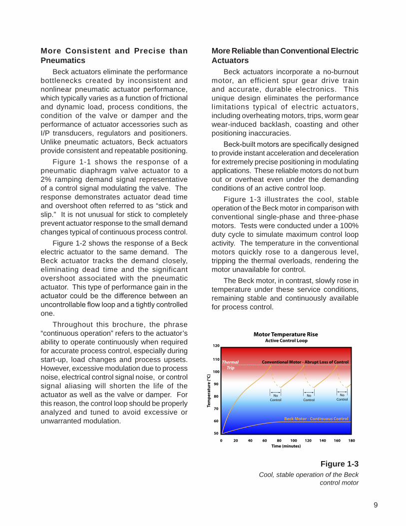
More Reliable than Conventional Electric Actuators Beck actuators incorporate a no-burnout motor, an efficient spur gear drive train and accurate, durable electronics. This unique design eliminates the performance limitations typical of electric actuators, including overheating motors, trips, worm gear wear-induced backlash, coasting and other positioning inaccuracies. Beck-built motors are specifically designed to provide instant acceleration and deceleration for extremely precise positioning in modulating applications. These reliable motors do not burn out or overheat even under the demanding conditions of an active control loop. Figure 1-3 illustrates the cool, stable operation of the Beck motor in comparison with conventional single-phase and three-phase motors. Tests were conducted under a 100% duty cycle to simulate maximum control loop activity. The temperature in the conventional motors quickly rose to a dangerous level, tripping the thermal overloads, rendering the motor unavailable for control. The Beck motor, in contrast, slowly rose in temperature under these service conditions, remaining stable and continuously available for process control.
Figure 1-3Cool, stable operation of the Beck
control motor
Thermal Trip
Time (minutes)
Tem
pera
ture
(°C)
0
50
60
70
80
90
100
110
120
20 40 60 80 100 120 140 160 180
Motor Temperature Rise Active Control Loop
Conventional Motor - Abrupt Loss of Control
NoControl
NoControl
NoControl

10
11
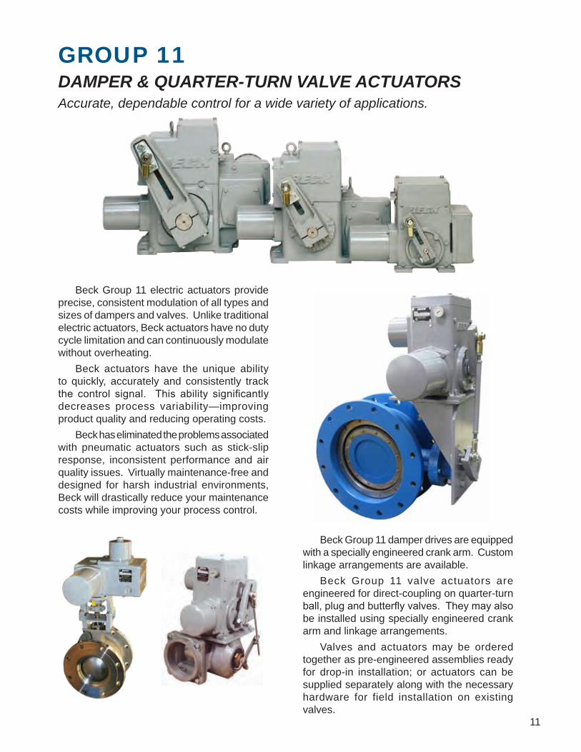
GROUP 11DAMPER & QUARTER-TURN VALVE ACTUATORSAccurate, dependable control for a wide variety of applications.
Beck Group 11 electric actuators provide precise, consistent modulation of all types and sizes of dampers and valves. Unlike traditional electric actuators, Beck actuators have no duty cycle limitation and can continuously modulate without overheating. Beck actuators have the unique ability to quickly, accurately and consistently track the control signal. This ability significantly decreases process variability—improving product quality and reducing operating costs. Beck has eliminated the problems associated with pneumatic actuators such as stick-slip response, inconsistent performance and air quality issues. Virtually maintenance-free and designed for harsh industrial environments, Beck will drastically reduce your maintenance costs while improving your process control.
Beck Group 11 damper drives are equipped with a specially engineered crank arm. Custom linkage arrangements are available. Beck Group 11 valve actuators are engineered for direct-coupling on quarter-turn ball, plug and butterfly valves. They may also be installed using specially engineered crank arm and linkage arrangements. Valves and actuators may be ordered together as pre-engineered assemblies ready for drop-in installation; or actuators can be supplied separately along with the necessary hardware for field installation on existing valves.
12
FEATURES
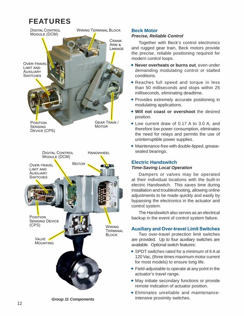
Group 11 Components
Beck MotorPrecise, Reliable Control Together with Beck’s control electronics and rugged gear train, Beck motors provide the precise, reliable positioning required for modern control loops.• Never overheats or burns out, even under
demanding modulating control or stalled conditions.
• Reaches full speed and torque in less than 50 milliseconds and stops within 25 milliseconds, eliminating deadtime.
• Provides extremely accurate positioning in modulating applications.
• Will not coast or overshoot the desired position.
• Low current draw of 0.17 A to 3.0 A, and therefore low power consumption, eliminates the need for relays and permits the use of uninterruptible power supplies.
• Maintenance-free with double-lipped, grease-sealed bearings.
Electric HandswitchTime-Saving Local Operation Dampers or valves may be operated at their individual locations with the built-in electric Handswitch. This saves time during installation and troubleshooting, allowing online adjustments to be made quickly and easily by bypassing the electronics in the actuator and control system. The Handswitch also serves as an electrical backup in the event of control system failure.
Auxiliary and Over-travel Limit Switches Two over-travel protection limit switches are provided. Up to four auxiliary switches are available. Optional switch features:• SPDT switches rated for a minimum of 6 A at
120 Vac, (three times maximum motor current for most models) to ensure long life.
• Field-adjustable to operate at any point in the actuator’s travel range.
• May initiate secondary functions or provide remote indication of actuator position.
• Eliminates unreliable and maintenance- intensive proximity switches.
Position Sensing Device (CPS)
Digital Control Module (DCM)
Over-travel Limit and Auxiliary Switches
Wiring Terminal Block
Crank Arm &Linkage
Gear Train /Motor
Position Sensing Device (CPS)
Over-travel Limit and Auxiliary Switches
Wiring TerminalBlock
Digital Control Module (DCM)
Motor
Handwheel
ValveMounting

13
Drive TrainPower and Durability to Maximize Control Availability Beck’s durable gear train maintains accurate, consistent control element positioning even under the demanding conditions of an active control loop.• Gear trains employ a unique, all spur gear
construction of heat-treated alloy steels and ductile iron.
• Efficient, wide-face spur gearing essentially eliminates wear-induced backlash and positioning inaccuracies.
• Durable design provides up to 4 days of protection against intermittent or extended accidental stalls.
• Integral self-locking mechanism ensures that drives hold a minimum of 200% of rated torque with the motor de-energized.
Manual HandwheelConvenient Manual Control Without Declutch An easy-to-turn, spoke-free Handwheel is incorporated into the Group 11 design to allow manual operation during installation or power outages.• Handwheel can be used to move valves and
dampers to any position smoothly and easily under full load conditions.
• Mechanical stops in housing prevent manual overtravel.
• The motor operates at 72 or 120 RPM, so the Handwheel poses no safety hazard.
HousingSuperior Protection and ConvenientAccess to Components Beck actuators feature a cast aluminum body with individual compartments to protect components from moisture and dirt, and allow easy access for installation and calibration.• Precision-machined aluminum alloy castings
with corrosion-resistant poly-urethane paint provide a rugged, dust-tight, weatherproof Type 4X enclosure. Models approved for use in Hazardous classified locations are available—contact a Beck Sales or Application Engineer for details.
• Individual compartments protect all major components: Motor, DCM, CPS, gear train and installation wiring terminal board.
• Each compartment can be accessed without exposing other components.
• Gasketed, precision-machined covers provide extra protection for harsh indoor and outdoor environments.
• Output and Handwheel shafts are also sealed with weatherproof, double-lip seals.
Mounting VersatilityBeck Actuators can be Mounted in any Orientation for Greater Installation Flexibility Beck actuators are configured and lubricated in such a way that they may be mounted in any convenient position. This flexibility allows actuators to be installed in hard-to-fit locations. If housing compartments are accessible, there are no mounting orientation limits.
Mounting ArrangementsDirect-Coupled Configurations A factory machined coupling is used to connect the actuator directly to the valve. This configuration is compact in design and is ideal for applications where a constant torque is desired over the full 90º range of travel.Crank Arm / Linkage Configurations Valve / actuator assemblies may be specified with crank arm and linkage mounting arrangement. This design allows 100º actuator travel, thus providing variable torque distribution and increased seating effectiveness.• With linkage characterization, high seating
torques can be obtained for certain valve types.
• Standard bracket and linkage mounting hardware is available for most popular valve types.
• Custom mountings are easily handled allowing Beck actuators to be economically mounted to virtually any rotary valve.
• Link-Assist™ computer program helps you specify the ideal arrangement for your application (see Appendix).

14
CONTROL OPTIONS & SAMPLE WIRING DIAGRAMS
Modulating Option 9Digital Position Control withContactless Position SensingThe Beck DCM positions the actuator in proportion to an input current or voltage signal, and the CPS provides integral feedback for the DCM. A 4–20 mA position feedback signal is available for remote indication. Foundation Fieldbus is also available.The DCM may be used to provide pre-determined positioning of the actuator upon loss of input control signal.
Modulating Option 8Analog Position Control withContactless Position SensingThe Beck ESR positions the actuator in proportion to an input current or voltage signal, and the CPS provides integral feedback for the ESR and isolated feedback for remote position indication (also available without external feedback).The ESR may be used to provide pre-determined positioning of the actuator upon loss of input control signal.
Modulating Option 7Analog Position Control withPotentiometer Position SensingThe Beck ESR positions the actuator in proportion to an input current or voltage signal. A film potentiometer is used in place of the CPS for position sensing and internal feedback to the ESR.An optional auxiliary potentiometer, requiring external power, may be added for remote position indication or control. The ESR may be used to provide predetermined positioning of the drive upon loss of input control signal.
Modulating Option 6Direct AC Control withContactless Position SensingControl option 6 features clockwise / counterclockwise control from a remote automatic controller or manual switches.The CPS provides a feedback signal for remote position indication.If the available 120 / 240 Vac control voltage is not able to supply enough current to operate a actuator, a Relay Board must be added to the control compartment.
HANDSWITCH
AUTO
CCW
CW
AUTO
ALARM
J1
POSITIONFEEDBACK
4-20 MA800 MAX.
J2
CCW
CW
F N
E
D M
V
U
MOTOROVER-TRAVEL
LIMITS
B
A
C
NEUTRAL
120 VACLINE
DEMANDINPUT
SIGNAL
AA
BB
CPS
DCM
EE
DD
JA
BLU
BLU
BLU
BLU
BLK
BLK
BLK
BLK
RED
BRN
GRN
ORG
GRY
WHT
WH
T
VIO
OR
GYE
LG
RN G
RN
GR
N
GR
N
BLK
BLK
RED
RED RED
YEL
YEL
YEL
( )
( )
( )
( )
2 157
913
11543
1
31
R+
Diagrams are functional—customer wiring may vary. Certified wiring diagrams can be provided for the actuator you select.

15
Modulating Option 5Direct AC Control withPotentiometer Position SensingActuated in clockwise or counterclockwise from a remote location or manual switches, this configuration includes a 1000 ohm film potentiometer for remote feedback. An optional auxiliary 1000 ohm potentiometer can be added as an additional remote position indication.If the available 120 / 240 Vac control voltage is not able to supply enough current to operate a actuator, a Relay Board must be added to the control compartment.
Multi-Position Option 4Direct AC Control with Cam-OperatedSwitches to Stop Actuator TravelOption 4 incorporates adjustable cam-operated switches to stop the actuator in 6 positions (two end-of-travel, four intermediate positions), or 3 positions (one intermediate position). 4-position and 5-position control can also be attained using a different number of switches.Standard end-of-travel switches have extra contacts that can be used for external signaling or interlocking.Configuration shown: BASIC 3-position.
Open / Close Option 3Direct AC ControlFor simple open / close operation, Option 3 includes two limit switches, which stop the actuator at each end of travel and may also be used for external signaling.
Other operating voltages availableAll of the options described on this page and the previous page are also available for 208, 240, 380, 415, 480 & 575 Vac operation instead of 120 Vac operation.
Auxiliary Switch TerminalsAuxiliary switches may be added for control or annunciation functions. Switches are rated at 6 A 120 Vac. They may be factory-set or field-adjusted to operate at any point in the actuator’s travel.
16
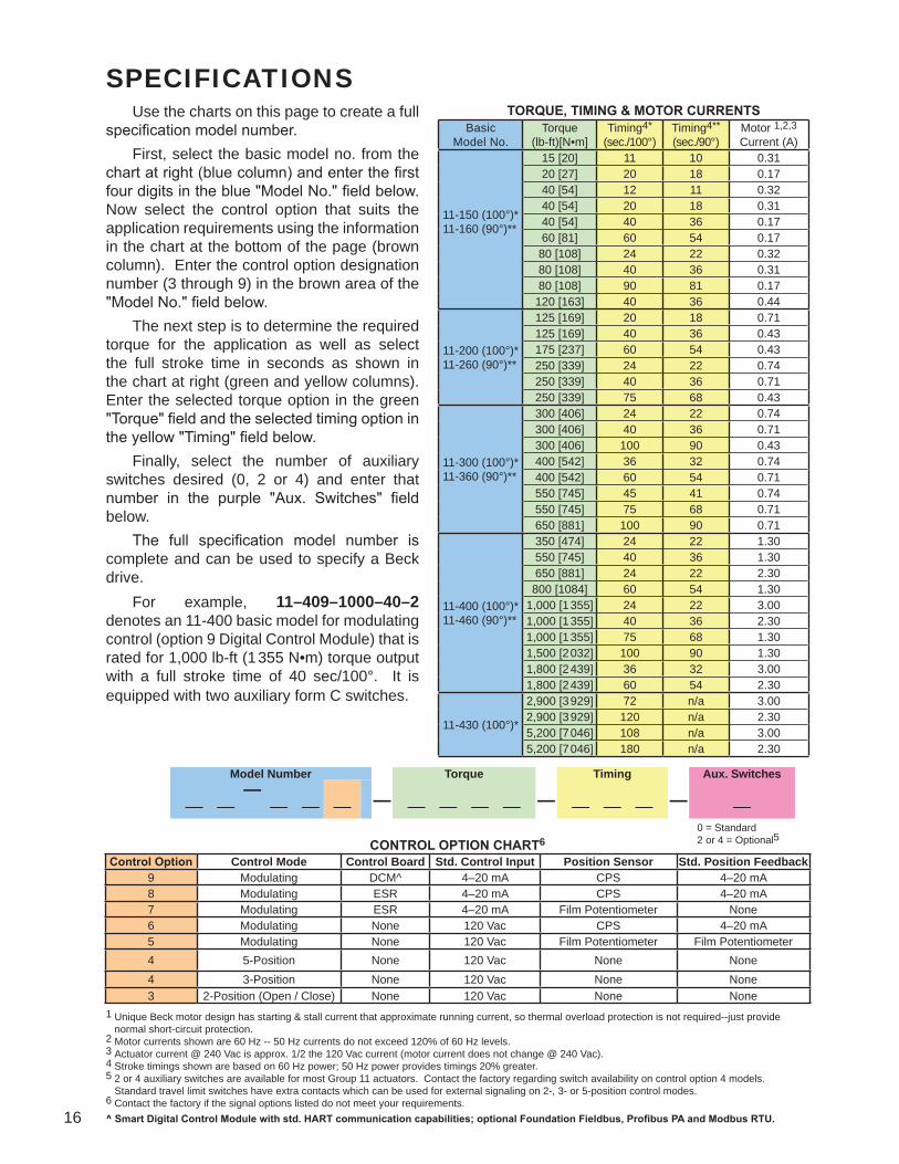
SPECIFICATIONSTORQUE, TIMING & MOTOR CURRENTS
1 Unique Beck motor design has starting & stall current that approximate running current, so thermal overload protection is not required--just provide normal short-circuit protection.2 Motor currents shown are 60 Hz -- 50 Hz currents do not exceed 120% of 60 Hz levels.3 Actuator current @ 240 Vac is approx. 1/2 the 120 Vac current (motor current does not change @ 240 Vac).4 Stroke timings shown are based on 60 Hz power; 50 Hz power provides timings 20% greater.5 2 or 4 auxiliary switches are available for most Group 11 actuators. Contact the factory regarding switch availability on control option 4 models. Standard travel limit switches have extra contacts which can be used for external signaling on 2-, 3- or 5-position control modes.6 Contact the factory if the signal options listed do not meet your requirements.^ Smart Digital Control Module with std. HART communication capabilities; optional Foundation Fieldbus, Profibus PA and Modbus RTU.
0 = Standard2 or 4 = Optional5
Use the charts on this page to create a full specification model number. First, select the basic model no. from the chart at right (blue column) and enter the first four digits in the blue "Model No." field below. Now select the control option that suits the application requirements using the information in the chart at the bottom of the page (brown column). Enter the control option designation number (3 through 9) in the brown area of the "Model No." field below. The next step is to determine the required torque for the application as well as select the full stroke time in seconds as shown in the chart at right (green and yellow columns). Enter the selected torque option in the green "Torque" field and the selected timing option in the yellow "Timing" field below. Finally, select the number of auxiliary switches desired (0, 2 or 4) and enter that number in the purple "Aux. Switches" field below. The full specification model number is complete and can be used to specify a Beck drive. For example, 11–409–1000–40–2 denotes an 11-400 basic model for modulating control (option 9 Digital Control Module) that is rated for 1,000 lb-ft (1 355 N•m) torque output with a full stroke time of 40 sec/100°. It is equipped with two auxiliary form C switches.
BasicModel No.
Torque(lb-ft)[N•m]
Timing4* (sec./100°)
Timing4** (sec./90°)
Motor 1,2,3Current (A)
11-150 (100°)* 11-160 (90°)**
15 [20] 11 10 0.3120 [27] 20 18 0.1740 [54] 12 11 0.3240 [54] 20 18 0.3140 [54] 40 36 0.1760 [81] 60 54 0.1780 [108] 24 22 0.3280 [108] 40 36 0.3180 [108] 90 81 0.17120 [163] 40 36 0.44
11-200 (100°)* 11-260 (90°)**
125 [169] 20 18 0.71125 [169] 40 36 0.43175 [237] 60 54 0.43250 [339] 24 22 0.74250 [339] 40 36 0.71250 [339] 75 68 0.43
11-300 (100°)* 11-360 (90°)**
300 [406] 24 22 0.74300 [406] 40 36 0.71300 [406] 100 90 0.43400 [542] 36 32 0.74400 [542] 60 54 0.71550 [745] 45 41 0.74550 [745] 75 68 0.71650 [881] 100 90 0.71
11-400 (100°)* 11-460 (90°)**
350 [474] 24 22 1.30550 [745] 40 36 1.30650 [881] 24 22 2.30800 [1084] 60 54 1.30
1,000 [1 355] 24 22 3.001,000 [1 355] 40 36 2.301,000 [1 355] 75 68 1.301,500 [2 032] 100 90 1.301,800 [2 439] 36 32 3.001,800 [2 439] 60 54 2.30
11-430 (100°)*
2,900 [3 929] 72 n/a 3.002,900 [3 929] 120 n/a 2.305,200 [7 046] 108 n/a 3.005,200 [7 046] 180 n/a 2.30
Model Number Torque Timing Aux. Switches— — — —— — — — — — — — — — — — —
CONTROL OPTION CHART6
Control Option Control Mode Control Board Std. Control Input Position Sensor Std. Position Feedback9 Modulating DCM^ 4–20 mA CPS 4–20 mA8 Modulating ESR 4–20 mA CPS 4–20 mA7 Modulating ESR 4–20 mA Film Potentiometer None6 Modulating None 120 Vac CPS 4–20 mA5 Modulating None 120 Vac Film Potentiometer Film Potentiometer4 5-Position None 120 Vac None None4 3-Position None 120 Vac None None3 2-Position (Open / Close) None 120 Vac None None

17
Input Power 120 Vac, single-phase 50 or 60 Hz 208, 240, 380, 415, 480, 575 Vac, 50 or 60 Hz—requires optional integral transformerOperating Conditions –40º to 85ºC (–40º to 185ºF) –50º to 85ºC (–58º to 185ºF); optional for 11-200/-300-400 models 0 to 100% relative humidityIsolation Demand Input and Position Feedback signals are isolated from the ground and the ac power line.Action on Loss of Power Stays in place.Control Types Modulating with Digital Control Module (DCM) Modulating with analog electronics (ESR) Modulating direct ac motor control 3 or 5 position control 2 position (open/close) controlInput and Feedback Signals Depends upon the actuator control option. See page 16.Available Communication Protocols (control option 9) HART® (standard). Options: Foundation Fieldbus, Profibus PA and Modbus RTU.Minimum Step Size (Modulating Control) DCM -- 0.10% (0.15% typical) (configurable) ESR -- 0.10% (0.15% typical) Direct AC -- 0.1° (function of control system capabilities)Stall Protection (protects actuator and driven elements under stall conditions) DCM -- Time to stall is configurable from 30 to 300 seconds. Other control types -- Optional Stall Protection Module is available.Action on Loss of Input Signal (Power On) Stays in place or, with some options, is field configurable to move to any preset position.Overtravel Limit Switches (Dedicated) Two Form C switches provide overtravel protection.Auxiliary Switches (Non-Dedicated) Up to four 6A, 120 Vac switches available. Switches are cam-operated and field-adjustable.Handswitch Permits local electrical operation independent of the controller signal. Standard on all units. An optional
auxiliary contact can be used to indicate that the Handswitch is in "AUTO" mode or to sound an alarm if it is taken out of "AUTO". A locking Handswitch is also available.
Enclosure Precision-machined, aluminum alloy castings painted with corrosion-resistant polyurethane paint provide
a rugged, dust-tight, weatherproof enclosure. Type 4X; IP68, 3 meters/48 hours. NOTE: Internal water damage is not covered by warranty.
Standards CSA Labeled (US & Canada); CE Compliant NOTE: For standards not specifically listed, please call Beck for more information at 215-968-4600.
Hazardous Locations (Optional) Class I, Div. 2, Groups A, B, C & D; Class II, Div. 1, Groups E, F & G; Class II, Div. 2, Groups F & G;
Class III, Div. 1 & 2. NOTE: May not be available with all options & models. If these ratings do not meet your requirements, call Beck at 215-968-4600.
Mounting Orientation Any orientation—no limitations.

18
OUTLINE DIMENSION DRAWINGS
Crank Arm
68
10
42
0
10
86
42
0
6 7/8"(175 mm)
4"(102 mm)
34
COVER, DIGITALCONTROL MODULE(ALLOW 4" (102 mm)
FOR REMOVAL)COVER,
TERMINAL BLOCKEXTERNAL WIRING
COVER, POSITIONSENSING DEVICES
4 1/2"(114 mm)
4 1/2"(114 mm)
4"(102 mm)
11 5/8" (295 mm)(ALLOW 6" (152 mm)
FOR REMOVAL)
HANDSWITCH
CRANK ARMSCREW
R
ADJUSTABLE RADIUS "R" 1 1/2" (38 mm) TO 5 1/8" (130 mm)
L
6"(152 mm)
ROD END BOLT
ROD END
WASHERS (2)
WEDGE
ROD ENDLOCK NUT
4 1/4"(108 mm)
1" N.P.T.CONDUIT,
POWERCONNECTION
2 3/16"(56 mm)
1" N.P.T.CONDUIT,SIGNALCONNECTION
HANDWHEEL
GEAR MODULE /MOTOR ASSEMBLY
1/2"(13 mm)
13/32" (10 mm) DIA.(4) HOLES
1/2" (13 mm)
7"(178 mm)
1 3/4" (45 mm)2 1/4" (57 mm)
LINKAGE CL 12 7/8" (327 mm) MAX.(ALLOW 4" (102 mm)
FOR REMOVAL)
3 9/16" (90 mm)
RL
T
13 1/2"(343 mm)
11 1/16"(281 mm)
3/4" (19 mm) OR 1 1/2" (38 mm) DIA.
1 15/32(37 mm)
COVER, DIGITALCONTROL MODULE(ALLOW 4" (102 mm)
FOR REMOVAL
6 7/8"(175 mm)
13 1/4"(337 mm)
3 1/4"(83 mm)
MOUNTING HOLES3/8-16 UNC-2B x 1/2" (13 mm) DEEP
(4) HOLES EQUALLY SPACEDON A 5" (127 mm) DIA. B.C.
11 5/8" (295 mm)(ALLOW 6" (152 mm)
FOR REMOVAL)
45°
COVER, POSITIONSENSING DEVICES
HANDSWITCH
COVER,TERMINAL BLOCK
EXTERNAL WIRING
HANDWHEEL
9 3/8" (238 mm) MAX.(ALLOW 4" (102 mm)
FOR REMOVAL)
3 7/8" (98 mm)
+.001" (.03 mm)–.000
7 1/2"(191 mm)1" N.P.T.
CONDUIT,SIGNAL
CONNECTION
1" N.P.T.CONDUIT,
POWERCONNECTION
2 3/16"(56 mm)
2 7/16"(62 mm)
GEAR MODULE /MOTOR ASSEMBLY
4 7/16" (113 mm)
Actuators may be mounted in any orientation.All dimensions are subject to change. Request certified dimensional drawings for the actuators you select.
Model 11-150
Model 11-160

19
Crank Arm
10
10
2
2
4
4
6
6
8
8
0
0
COVER,TERMINAL BLOCK
EXTERNAL WIRING
COVER,DIGITAL
CONTROLMODULE
COVER,POSITIONSENSINGDEVICES
HANDSWITCH
GEAR MODULEASSEMBLY
34°
5 1/2"(140 mm)6 3/8"
(162 mm)6 3/8"
(162 mm)
5 1/2"(140 mm)
12 3/4"(324 mm)
12 1/4" (311 mm)(ALLOW 6 " (152 mm)
FOR REMOVAL)
11/16" (17 mm) DIA.(4) HOLES
AUX. SWITCH RATING:10A 240 Vac
1" N.P.T.CODUIT,POWER
CONNECTION
6 7/32"(158 mm)
4 25/32"(121 mm)
1" N.P.T.CONDUIT,SIGNALCONNECTION
NAMEPLATE
MOTOR
T
18"(457 mm)
15 5/8"(397 mm)
L
R
6"(153 mm)
5 5/8"(143 mm)
6 1/2"(165 mm)
3/4"(19 mm)
3/4"(19 mm)
7/8"(22 mm)
4 1/4"(108 mm)
11 3/8" (290 mm) MAX.(ALLOW 3" (76 mm)
FOR REMOVAL)4 3/4"(121 mm)
LINKAGE CL
9 1/4"(235 mm)
R
L
ADJUSTABLE RADIUS "R"3 1/2" (89 mm) TO 8" (203 mm) ROD END
CRANKARM
SCREW (2)
NUT PLATE
CLAMP PLATE
CRANK PIN / STUD
ROD END LOCK NUT
CRANK PIN SCREW
CRANK ARM SCREW (2)
Model 11-260/-360
Model 11-200/-300
NAMEPLATE1” N.P.T. CONDUITSIGNALCONNECTION
1” N.P.T. CONDUITPOWER CONNECTION
9 21/32”[245]
10”[254]
AUX. SWITCH RATING:10A 240 Vac
HANDWHEEL
GEAR MODULE ASSEMBLY
SEETABLE,
P.15
2 1/8”[54]
4 7/16”[113]
Ø1.956 +.004–.000
[Ø49.682 ]+.102–.000
7 3/8”[187]
8 1/8” [206] MAX.(ALLOW 3” [76] FOR REMOVAL)
DIMENSION DEPENDENTON VALVE
SIZE
DIMENSION DEPENDENTON VALVE
SIZE
COVER, DIGITALCONTROLMODULE
COVER, POSITIONSENSING DEVICES
MOUNTING HOLES1/2-13 UNC-2B x 3/4” [19] DEEP (4) HOLES
EQUALLY SPACEDON A 5” [127] DIA. B.C.
COVER, TERMINAL BLOCKEXTERNAL WIRING
HANDSWITCH
45º
12 1/4”[311]
(ALLOW 6” [152] FOR REMOVAL)
12 3/4”[324]
5 5/8”[143]
18”[457]
20
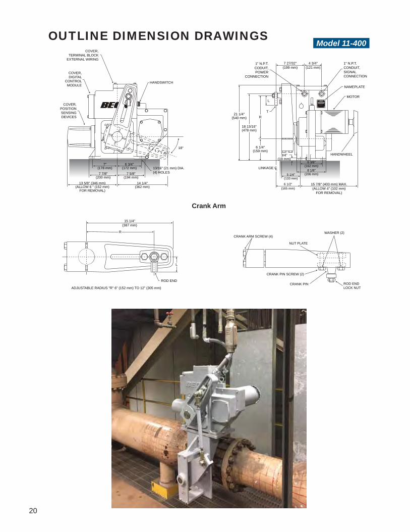
OUTLINE DIMENSION DRAWINGS
Crank Arm
COVER,TERMINAL BLOCK
EXTERNAL WIRING
COVER,DIGITAL
CONTROLMODULE
COVER,POSITIONSENSINGDEVICES
HANDSWITCH
18°
7"(178 mm)
6 3/4"(172 mm)
7 7/8"(200 mm)
7 5/8"(194 mm)
14 1/4"(362 mm)
13 5/8" (346 mm)(ALLOW 6 " (152 mm)
FOR REMOVAL)
13/16" (21 mm) DIA.(4) HOLES
AUX. SWITCH RATING:10A 240 Vac
1" N.P.T.CODUIT,POWER
CONNECTION
7 27/32"(199 mm)
4 3/4"(121 mm)
1" N.P.T.CONDUIT,SIGNALCONNECTION
NAMEPLATE
MOTOR
T21 1/4"
(540 mm)
18 13/16"(478 mm)
6 1/4"(159 mm)
L
R
5 1/4"(133 mm)
6 3/8"(162 mm)
8 1/8"(206 mm)
15 7/8" (403 mm) MAX.(ALLOW 4" (102 mm)
FOR REMOVAL)
6 1/2"(165 mm)
LINKAGE CL
3/4"(19 mm)
HANDWHEEL
15 1/4"(387 mm)
R
L
ROD END
ADJUSTABLE RADIUS "R" 6" (152 mm) TO 12" (305 mm)
CRANK ARM SCREW (4)WASHER (2)
NUT PLATE
CRANK PIN SCREW (2)
CRANK PIN ROD ENDLOCK NUT
Model 11-400

21
Mechanical Specifications
Crank Arm & Rod End Supplied as Standard Beck
ActuatorModel
NumberApprox. Wt.(lbs) [kgs]*
Output ShaftDiameter(in) [mm]
Crank ArmPart
Number
Crank Arm Radius "R" (adjustable)(in) [mm]**
Rod End Length "L" Dimension(in) [mm]
Rod End Internal
Thread "T" (in) [mm]
MaximumOverhung
Load(lbs) [kgs]
11-150 (50)[23]
(.75)[19] 10-3491-05 (1.5 - 5.125)
[38 - 130](2.125)
[54](1/2-20 x 1.1875)
[1/2-20 x 30](750)[340]
11-200 (120)[54]
(1.5)[38] 14-7330-40 (3.5 - 8)
[89 - 203](2.125)
[54](1/2-20 x 1.1875)
[1/2-20 x 30](3,000)[1 361]
11-300 (125)[57]
(1.75)[44] 14-8010-34 (3.5 - 8)
[89 - 203](2.5)[64]
(5/8-18 x 1.5)[5/8-18 x 38]
(4,500)[2 041]
11-400 (270)[122]
(2.75)[70] 14-8018-02 (6 - 12)
[152 - 305](2.875)
[73](3/4-16 x 1.75)[3/4-16 x 44]
(9,000)[4 082]
*Approx. weights are the same for the 11-160, -260, -360 & -460 and their counterparts in the table above.**Longer or shorter crank arms allowing for a greater or lesser radius are available as an option.
Model 11-460
Actuators may be mounted in any orientation.All dimensions are subject to change. Request certified dimensional drawings for the actuators you select.
COVER,POSITIONSENSINGDEVICES
HANDSWITCH
MOUNTING HOLES5/8-11 UNC-2B x 1.63" (41.4 mm) DEEP(4) HOLES EQUALLY SPACEDON A 9.75" (248 mm) DIA. B.C.
21 1/4"(540 mm)
6 1/4"(159 mm)
13 5/8" (346 mm)(ALLOW 6" (152 mm)
FOR REMOVAL)
14 1/4"(362 mm)
COVER,TERMINAL BLOCK
EXTERNAL WIRING
COVER,DIGITAL
CONTROLMODULE
HANDWHEEL
GEAR MODULEASSEMBLY
2 3/4" (69.85 mm) DIA.+.001" (.03 mm)–.000
3 3/4"(95 mm)
7 3/4"(197 mm)
13 3/8" (340 mm) MAX.(ALLOW 4" (102 mm)
FOR REMOVAL)
OPTIONALTRANSFORMERENCLOSURE W/
SOME POWEROPTIONS
AUX.
SW
ITC
H R
ATIN
G:
10A
240
Vac
1" N.P.T.CONDUIT,
SIGNALCONNECTION
12 9/16"(319 mm)
1" N.P.T.CONDUIT,POWERCONNECTION
4 3/4"(121 mm)
NAMEPLATE
2 19/32(66 mm)
11 5/8” max.(295 mm max.)
DIMENSIONDEPENDENT
ON VALVE SIZE
DIMENSIONDEPENDENT
ON VALVE SIZE
OPTIONALTRANSFORMERENCLOSURE W/
SOME POWEROPTIONS
22
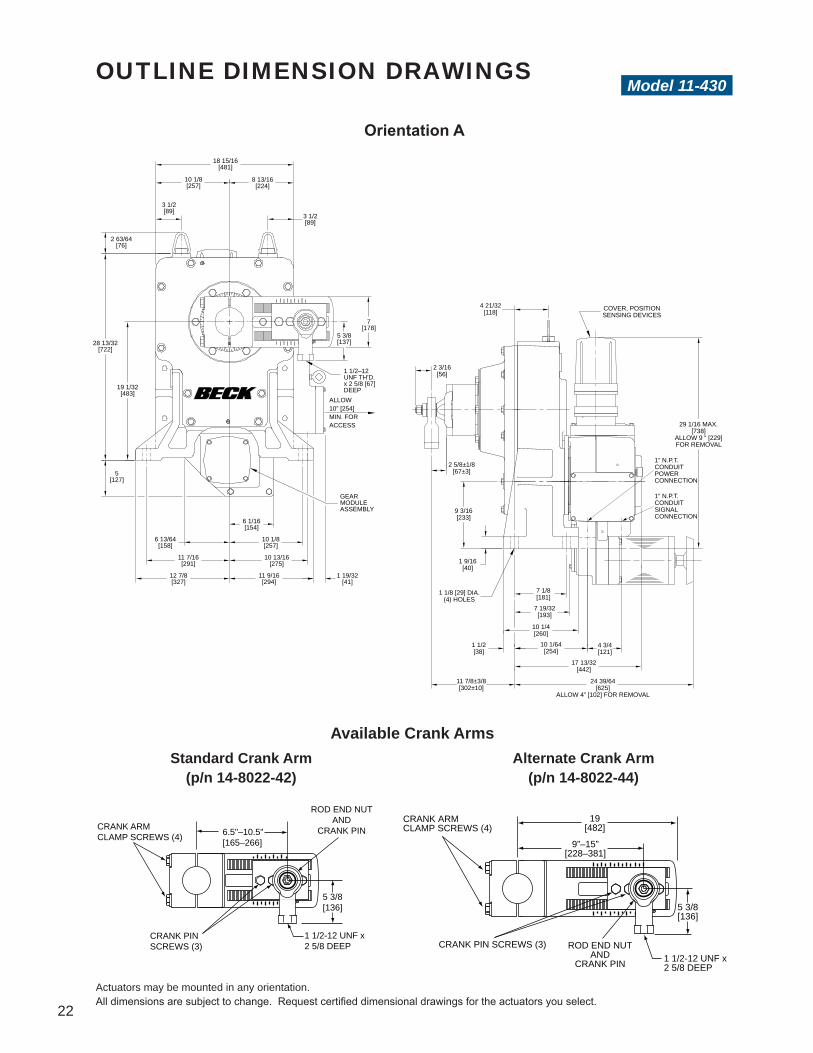
Orientation A
CRANK ARM CLAMP SCREWS (4) 6.5"–10.5"
[165–266]
CRANK PIN SCREWS (3)
ROD END NUTAND
CRANK PIN
1 1/2-12 UNF x2 5/8 DEEP
5 3/8[136]
CRANK ARM CLAMP SCREWS (4)
CRANK PIN SCREWS (3) ROD END NUTAND
CRANK PIN
9”–15”[228–381]
19[482]
5 3/8[136]
1 1/2-12 UNF x2 5/8 DEEP
Available Crank ArmsStandard Crank Arm
(p/n 14-8022-42)Alternate Crank Arm
(p/n 14-8022-44)
18 15/16[481]
10 1/8[257]
8 13/16[224]
2 63/64[76]
3 1/2[89]
3 1/2[89]
28 13/32[722]
7[178]
5 3/8[137]
19 1/32[483]
1 1/2–12 UNF TH’D. x 2 5/8 [67]DEEP
5[127]
ALLOW 10” [254]MIN. FOR ACCESS
GEAR MODULEASSEMBLY
6 13/64[158]
6 1/16[154]
11 7/16[291]
12 7/8[327]
10 1/8[257]
10 13/16[275]
11 9/16[294]
1 19/32[41]
4 21/32[118] COVER, POSITION
SENSING DEVICES
2 3/16[56]
2 5/8±1/8[67±3]
9 3/16[233]
1 9/16[40]
1 1/2[38]
11 7/8±3/8[302±10]
7 1/8[181]
7 19/32[193]
10 1/4[260]
10 1/64[254]
4 3/4[121]
17 13/32[442]
24 39/64[625]
ALLOW 4” [102] FOR REMOVAL
1” N.P.T. CONDUITSIGNALCONNECTION
29 1/16 MAX.[738]
ALLOW 9 “ [229]FOR REMOVAL
1 1/8 [29] DIA.(4) HOLES
1” N.P.T. CONDUITPOWERCONNECTION
Model 11-430OUTLINE DIMENSION DRAWINGS
Actuators may be mounted in any orientation.All dimensions are subject to change. Request certified dimensional drawings for the actuators you select.

23
Orientation B
Approx.Wt.
(lb) [kg]
Output Shaft Dia.(in) [mm]
Max.Overhung
Load(lb) [kg]
790[358]
3 15/16[100]
20,000[9 072]
Crank Arm14-8022-42
or15,000[6 804]
Crank Arm14-8022-44
18 15/16[481]
10 1/8[257]
8 13/16[224]
3 1/2[89]
3 1/2[89]
2 63/64[76]
28 13/32[722]
19 1/32[483]
7[178]
GEARMODULEASSY.
7/8[22]
10 1/8[257]
11 9/16[294]
11 7/16[291]
12 7/8[327]
21 5/8[549]
ALLOW 9” [229] FOR REMOVAL
1” N.P.T. CONDUITPOWER CONNECTION
4 21/32[118]
ALLOW 10” [254]MIN. FOR ACCESS
COVER, TERMINAL BLOCKEXTERNAL WIRING
1” N.P.T. CONDUITSIGNAL CONNECTION
24 1/8[613]
21 3/4[553]
2 3/16[56]
2 5/8±1/8[67±3]
9 3/16[233]
1 9/16[40]
1 1/2[38]
11 7/8±3/8[302±10]
7 1/8[181]
10 1/4[260]
10 1/64[254]
17 13/32[442]
24 39/64[625]
4 3/4[121]

24

25
GROUP 22HIGH TORQUE DAMPER ACTUATORSHigh torque capability in a compact, modular design featuring advanced digital electronics and traditional Beck reliability.
Group 22 damper actuators offer excellent performance in a maintenance-free design, plus the added flexibility and features provided by microprocessor-based electronics.
Ideally suited for large fan damper applications, model 22-309, 22-409 and 22-809 actuators are capable of modulating both static and dynamic loads up to 8,000 lb-ft (10 839 N•m) of torque, even in the harshest of environments. Group 22 installation is simple due to a compact, weatherproof body design which houses all the components, including the advanced control module.

26
Gear TrainProven Durability Beck Group 22 actuators utilize a high-efficiency gear train designed for long life and minimal wear. The precision-cut spur gears are fabricated from heat-treated alloy steel and ductile iron.
Self-Locking Mechanism (SLM)Back-driving Protection A Self-Locking Mechanism is an integral part of the Group 22 actuator system. The SLM is a coupling that transmits motor torque to the gear train in either direction, but instantly locks in place when the motor is de-energized; thus preventing back-driving by dynamic loads.
FEATURESManual HandwheelConvenient Local Operation A manual Handwheel (and Handcrank on model 22-809 drives) is standard on all Group 22 models for use during installation and testing, or during power outages. This Handwheel does not require a declutch mechanism for operation and turns at a safe, slow speed.
Adjustable Crank ArmEasy Installation and Set up For ease of installation on any application, the Group 22 crank arm can be easily positioned to start anywhere in the full 360° rotation of the output shaft. To further facilitate proper installation and set up, the crank arm radius is easily adjustable through a wide range of values.
Group 22 Damper Actuator Component Locations (Model 22-309 shown)
Digital Control Module (DCM)
Contactless PositionSensor (CPS)
Handswitch
Motor
Handwheel
Wiring Terminal
Block
27
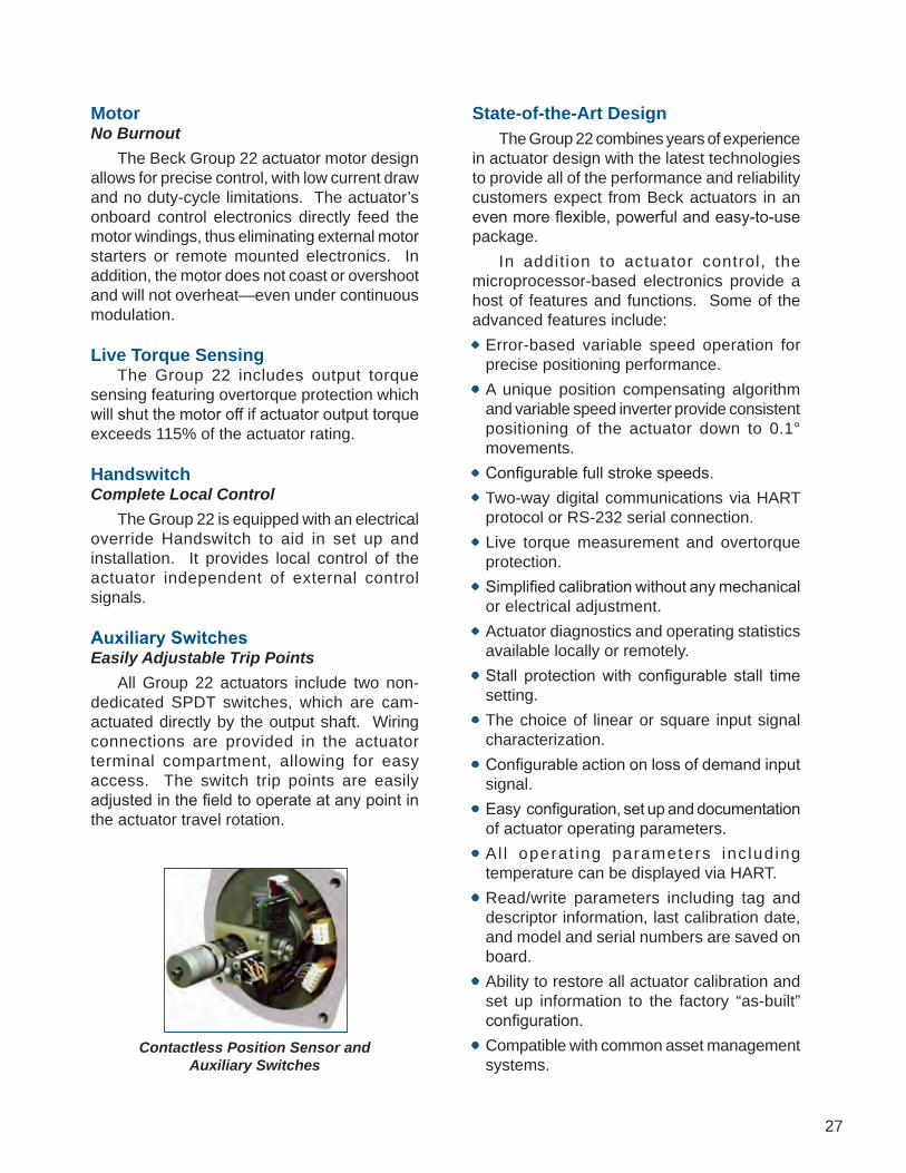
MotorNo Burnout The Beck Group 22 actuator motor design allows for precise control, with low current draw and no duty-cycle limitations. The actuator’s onboard control electronics directly feed the motor windings, thus eliminating external motor starters or remote mounted electronics. In addition, the motor does not coast or overshoot and will not overheat—even under continuous modulation.
Live Torque Sensing The Group 22 includes output torque sensing featuring overtorque protection which will shut the motor off if actuator output torque exceeds 115% of the actuator rating.
HandswitchComplete Local Control The Group 22 is equipped with an electrical override Handswitch to aid in set up and installation. It provides local control of the actuator independent of external control signals.
Auxiliary SwitchesEasily Adjustable Trip Points All Group 22 actuators include two non-dedicated SPDT switches, which are cam-actuated directly by the output shaft. Wiring connections are provided in the actuator terminal compartment, allowing for easy access. The switch trip points are easily adjusted in the field to operate at any point in the actuator travel rotation.
Contactless Position Sensor and Auxiliary Switches
State-of-the-Art Design The Group 22 combines years of experience in actuator design with the latest technologies to provide all of the performance and reliability customers expect from Beck actuators in an even more flexible, powerful and easy-to-use package. In addition to actuator control, the microprocessor-based electronics provide a host of features and functions. Some of the advanced features include:• Error-based variable speed operation for
precise positioning performance.• A unique position compensating algorithm
and variable speed inverter provide consistent positioning of the actuator down to 0.1° movements.
• Configurable full stroke speeds.• Two-way digital communications via HART
protocol or RS-232 serial connection.• Live torque measurement and overtorque
protection.• Simplified calibration without any mechanical
or electrical adjustment.• Actuator diagnostics and operating statistics
available locally or remotely.• Stall protection with configurable stall time
setting.• The choice of linear or square input signal
characterization.• Configurable action on loss of demand input
signal.• Easy configuration, set up and documentation
of actuator operating parameters.• Al l operat ing parameters inc luding
temperature can be displayed via HART.• Read/write parameters including tag and
descriptor information, last calibration date, and model and serial numbers are saved on board.
• Ability to restore all actuator calibration and set up information to the factory “as-built” configuration.
• Compatible with common asset management systems.

28
CONTROL OPTIONS & SAMPLE WIRING DIAGRAMSDiagrams are functional—customer wiring may vary. Certified wiring diagrams can be provided for the actuator you select.
Modulating Option 9Digital Position Control withContactless Position Sensing The Beck DCM positions the actuator in proportion to an input current or voltage signal, and the CPS provides integral feedback for the DCM. A 4–20 mA position feedback signal is available for remote indication. The DCM may be used to provide pre-determined positioning of the actuator upon loss of input control signal.
22-300
22-400 22-800

29
Actuator Current Rating in Amps (listed by operating voltage)* / Torque & Timing
Model No.
Operating Voltage (Volts AC) OutputTorque,
lb-ft [N•m]
Timing(configurable)
sec./100º1-phase 3-phase
120 240 208 240 380 416 480 57522-309 6.0 3.0 3.5 3.0 1.9 1.7 1.5 1.3 3,000 [4 065] 30–300
22-409 N/A N/A 4.0 3.5 2.2 2.0 1.7 1.44,000 [5 420] 15–3002,500 [3 387] 10–1802,000 [2 710] 08–150
22-809 N/A N/A 6.9 6.0 3.8 3.5 3.0 2.5 8,000 [10 839] 15–300 *Operating voltage tolerance is +10% to –15%. All models may be operated at 60 Hz or 50 Hz frequency. Standard operating voltage configurations are highlighted. Non-standard operating voltages for the 22-309 & 22-409 are available with an optional transformer.
SPECIFICATIONS
Weight 22-309, 22-409—540 lbs [245 kgs]; 22-809—1,250 lbs [567 kgs]Operating Conditions –40° to 85° C. (–40° to 185° F.); 0 to 99% relative humidityDemand Input Signal Range 4–20 mA, 1–5 VdcCommunication Protocol HART® Foundation™ technology (standard). Available options: Foundation Fieldbus, Profibus PA Minimum Step 0.1° typicalLinearity ±1% of span, max. independent errorHysteresis 0.25% of span at any pointDemand Input Signal Characterization Linear: Actuator output shaft moves proportionally to the input signal. Square: Actuator output shaft moves proportionally to the square of the input signal.Position Feedback Signal 4–20 mAIsolation Demand input and position Feedback signals are isolated from ground and the ac power line. Signal buffering provides 24 Vdc isolation between the Demand and Feedback signals.Overtorque Protection If actuator output torque exceeds 115% of actuator rating, the motor will shut off (feature can be enabled / disabled).Action on Loss of Input Signal (Power On) Stays in place or runs to any preset position (configurable).Stall Protection (protects actuator and driven elements under stall conditions) If the motor tries to run in one direction for more than 300 seconds (configurable from 30–300), motor will shut off.Over-travel Protection Switches (Dedicated) Two Form C, one for CW and one for CCW limit of output shaft travel. Standard switch setting allows 100° of travel.Auxiliary Switches (Non-dedicated) Two Form C, rated for 1 A, 250 Vac—cam operated and field adjustable.Handswitch Permits local electrical operation, independent of Demand input signal.Handwheel (and Handcrank on the 22-809) Provides manual operation without electrical power.Enclosure Precision-machined, aluminum alloy castings painted with corrosion-resistant polyurethane paint provide a rugged, dust-tight, weatherproof enclosure. Type 4, 4X; IP66.Standards UL Listed; CE Compliant Note: For standards not specifically listed, please call Beck for more information at 215-968-4600.Mounting Orientation Upright, as depicted in outline dimension drawings.

30
OUTLINE DIMENSION DRAWINGS
Front ViewRear View
Side View
ModelNo.
Torque,lb-ft
[N•m]
Timingsec./100º
Approx. Weight,
lbs[kgs]
OutputShaft
Diameter,in [mm]
Max. Overhung
Load,lbs [kgs]
22-309 3,000[4 065] 30–300 540
[245]3.5[89]
15,000[6 804]
22-409 4,000[5 420] 15–300 540
[245]3.5[89]
15,000[6 804]
ModelNo.
Torque,lb-ft
[N•m]
Timingsec./100º
Approx. Weight,
lbs[kgs]
OutputShaft
Diameter,in [mm]
Max. Overhung
Load,lbs [kgs]
22-409 2,500[3 387] 10–180 540
[245]3.5[89]
15,000[6 804]
22-409 2,000[2 710] 08–150 540
[245]3.5[89]
15,000[6 804]
18 7/8[480]
1[25]
27 7/16[697] 5 3/8
[137]
1 1/2-12 UNF THREADx 2 5/8 [67] DEEP
16 1/16[408]
17[432]
3 5 /16[84]
5 5/8[144]
Ø 1 [25] THRU(4) PLACES
21°
HART®
COMM. PORT
COVER, TERMINAL BLOCKSEXTERNAL WIRING
COVER, POSITIONSENSING DEVICES
HART®
COMMUNICATIONPORT
HANDSWITCH
COVER, ELECTRONICCOMPARTMENT
3 7/8[98]
10[254]
2 3/16[56]
DATA PLATE
7[178]
17 7/8 [454]ALLOW 5” [127] FOR REMOVAL
18 11/16 [475]ALLOW 5” [127] FOR REMOVAL
4 1/4[108]
10 7/8[276]
9[229]
15/16[24]
5/16[8]
1” N.P.T. CONDUITINPUT POWER
1” N.P.T. CONDUITAUXILIARY SWITCHESAND ALARMS
5 1/8[130]
8[203]
13 3/8[340]
21 15/16[557]
#10 GROUNDSCREW
1” N.P.T. CONDUITINPUT & FEEDBACKSIGNALS
Model 22-309/-409
STANDARD CRANK ARM
SHORTER CRANK ARM OPTION
CRANK ARM SCREWS (4)
CRANK PIN SCREWS (3)
ROD END NUTAND
CRANK PIN9”–15”
[229–381]
CRANK ARM WASHERS (4)
5 3/8[137]
1 1/2-12 UNF x2 5/8 DEEP
CRANK ARM SCREWS (4) 6.5"–10"
[165–254]
CRANK PIN SCREWS (3)
ROD END NUTAND
CRANK PIN
1 1/2-12 UNF x2 5/8 DEEP
5 3/8[137]
Mechanical Specifications

31
Front View Rear View
Side View
STANDARD CRANK ARM
All dimensions are subject to change.Request certified dimensional drawings for the drives you select.
19 1/4[489]
3/4[19]
1 1/2[38]
5 3/8[137]
32 11/16[830]
32°
1 1/2–12 UNF THREADx 2 5/8 [67] DEEP
1 1/8 [29] DIA. THRU(4) PLACES
19 5/16[491]
20 1/2[521]
4 1/16[103]
7 9/16[192]
1 1/2[38]
COVER, ELECTRONICSCOMPARTMENT
HANDSWITCH
COVER, POSITIONSENSING DEVICES
COVERS, TERMINAL BLOCKSEXTERNAL WIRING
DATA PLATE4 5/8 R.[117 R.]
1” N.P.T. CONDUITINPUT AND FEEDBACKSIGNALS
3 5/8[92]
25 3/16[640]
16 1/32[407]
13 9/32[337]7 21/32
[194]
1” N.P.T. CONDUITAUXILIARY SWITCHESAND ALARMS
1” N.P.T. CONDUITINPUT POWER
27 3/16 [691]ALLOW 5” [127] FOR REMOVAL
3 7/16[87]
22 11/16 [576]ALLOW 5” [127] FOR REMOVAL
16 1/2[419]
13 3/4[349]
#10 GROUNDSCREW
8 3/8[213]
5 7/16[138]
1 3/8[35]
12 1/8[308]
CRANK ARMSCREWS (6)
CRANK PINSCREWS (3)
10"–15"[254–381]
ROD END NUTAND
CRANK PIN
1 1/2-12 UNF x2 5/8 [67] DEEP
5 3/8[137]
Mechanical Specifications
ModelNumber
Torque,lb-ft
[N•m]Timing
sec./100º
Approx. Weight,lbs [kgs]
OutputShaft
Diameter,in [mm]
Max. Overhung
Load,lbs [kgs]
22-809 8,000[10 839] 15–300 1,250
[567](4.75)[121]
(30,000)[13 608]
Model 22-809

32

33
The Group 31 incorporates the same type of motor used in Beck’s Group 11 and Group 14 drives, which provides millisecond response to signal commands in a modulating control loop. This no-burnout, non-coasting motor is capable of more than 60 starts per minute during process upsets and will remain cool and stable during operation for unparalleled online performance.
GROUP 31COMPACT ACTUATORS FOR LOW TORQUE DAMPER AND VALVE APPLICATIONS High reliability and responsiveness in a small package.
The Group 31 actuator is designed for coupling to small quarter-turn ball and butterfly valves. Its compact in-line design consists of an output section housing the drive train and motor, and a control module section containing the electronics. Together, these two sections provide an enclosure designed to meet Type 4 specifications for protection against corrosion, dust and moisture. A design that meets Type 7 specifications is also available.

34
FEATURESMotor and Drive TrainUnequaled Availability Beck’s Group 31 rotary actuators incorporate an exclusive no-burnout motor, so that online dependability of valves is ensured. Heat-treated alloy steel and ductile iron hypocycloidal gearing transmits torque smoothly and powerfully to the output shaft. The Beck-built control motor provides millisecond response to signal commands in a modulating control loop—eliminating the coasting and overshooting problems typical of outdated electric actuators. The motor stator of the Group 31 actuator is molded into the centerpiece, providing stable delivery of torque without overheating and without burning out.
Mechanical StopsProtection from Overtravel Damage Rugged mechanical stops are furnished as a standard component of the valve mounting assembly. These stops prevent over-travel damage to valves and limit drive travel during manual cycling to maintain proper orientation of the drive output shaft with respect to switches and controls. A built-in position indicator shows the valve position.
Manual HandwheelConvenient Local Operation A manual Handwheel is standard on all Group 31 models for use during installation and testing, or during power outages. This Handwheel does not require a declutch mechanism for operation and does not rotate during automatic operation.
Electronic Control ModuleAccurate Position Control Group 31 Analog Modulating actuators include a single electronic control module which receives a 4–20 mA or 1–5 Vdc input signal and provides a 4–20 mA or 1–5 Vdc feedback for position control and indication.• Electronic module has a deadband of 1.0% of
span with sensitivity of 25% of deadband.• The input signal span is nominally adjustable
from 50% to 125% of the 4 V span, with the zero adjustable up to 120% of span, providing flexibility for split range operation.
Group 31 Rotary Actuator Components
Limit & Auxiliary Switches Four cam-operated switches are included as part of the control module. Two switches open the motor circuit and function as end-of-travel limit switches, and two auxiliary switches are for external signaling as required by the user. The switch cams are driven directly by the actuator’s output shaft for accurate control.
WiringTerminalBoard
Position Sensing and Feedback Device
ManualHandwheel
Gear Trainand Motor
Housing
Travel Limitand Auxiliary
Switches
ElectronicControlModule

35
Electric HandswitchConvenient Local Operation Included in the Analog Modulating models is an integral electric Handswitch, which permits safe, local operation at the valve’s individual location. This feature saves time during installation and allows adjustments to be made quickly and easily.
Large Terminal BlockEasy Field Wiring The upper board on the Group 31 actuator provides wiring terminals for field connection. This board is easily accessible to minimize time needed for installation wiring and testing.
Position Feedback Beck Group 31 actuators equipped with feedback capability use a film potentiometer incorporated into the control module. All modulating models feature electronic position indication. Direct AC models allow controllers to monitor drive position as the controller output directly positions the drive. Analog control modulating models provide electronic signal receiver circuitry, which compares the position indication to the control loop demand signal and provides automatic control.
Dual Feedback Capability A l l models incorporat ing the f i lm potentiometer have dual feedback capability, permitting user choice of 2-wire or 4-wire field connection.• 2-wire systems for 4–20 mA feedback, as
follows. Either: 300 ohm max. load resistance, which requires
less than 35 Vdc external power supply. or: Up to 800 ohm max. load resistance, which
requires greater than 36 Vdc external power supply.
• 4-wire systems utilizing 120 Vac power supplied to the actuator.
Either: 4–20 mA feedback, 500 ohm max. load resistance. or: 1–5 Vdc feedback, 12,000 ohm min. load resistance. Connections for feedback selection are made in the field and need not be specified on order.
Low Power Consumption for Use with Uninterruptible Power Supplies The uniquely low power draw of Beck Group 31 actuators permits the use of various standard uninterruptible power supplies for operation during loss of AC power. Beck Sales Engineers can provide you with specifications on UPS equipment recommended for Beck drives.
Direct-Coupled Configurations The Group 31 actuator may be coupled directly to the valve by the use of a factory machined, heat-treated coupling. This configuration is compact in design. A factory designed yoke between the actuator and the valve provides rigidity and accessibility to mounting hardware.
Crank Arm / Linkage Configurations For appl icat ions requir ing l inkage connection, Beck Group 31 actuators can be furnished with a machined crank arm and mounting bracket. Beck hex linkage kits may be used to simplify final connections.
Factory Mounted Assemblies The relationship of valve, actuator and mounting / coupling configuration can be of critical importance in ensuring a successful installation. For this reason, Beck provides Group 31 actuators and valves together—factory mounted and tested for simple drop-in installation. These fully integrated, unitized assemblies are pre-engineered to match the mechanical and electronic requirements of your system.

36
CONTROL OPTIONS & SAMPLE WIRING DIAGRAMS
Option 3, ModulatingAnalog Position Control with DrivePowered Position Feedback Signal Customer must supply two wires to power the drive: One 120 Vac line (terminal 1), and one neutral (terminal 2). Customer must supply two wires for analog control: Connect to terminal 11 (-) and to terminal 12 (+). Customer may supply two additional wires to monitor the analog position feedback signal: Connect to terminal 13 (-) and to terminal 14 (+). The drive’s feedback circuit power supply is derived from the 120 Vac line, therefore the feedback signal must be wired to a "4-wire" type, non-powered analog input.
Analog Position Control with LoopPowered Position Feedback Signal Customer must supply two wires to power the drive: One 120 Vac line (terminal 1), and one neutral (terminal 2). Customer must supply two wires for the analog input control signal: Connect to terminal 11 (-) and to terminal 12 (+). The loop powered position feedback signal must be connected to a “2-wire” type analog input that provides a dc voltage over the signal wires (a dc voltage power supply must be wired in series with the signal wiring). If the dc supply is 24 to 35 volts, connect to terminal 14 (-) and to terminal 15 (+). If the dc power supply is 36 to 45 volts, reverse polarity and connect to terminal 14 (+) and to terminal 15 (-).
Option 2, ModulatingDirect AC Control with Loop Powered Position Feedback Signal Customer must supply three wires to directly control the drive motor direction: One 120 Vac line to run Forward (terminal 10), one 120 Vac line to run Reverse (terminal 9), and one neutral (terminal 2). Customer may supply two additional wires to monitor a loop powered position feedback signal. The loop powered position feedback signal must be connected to a “2-wire” type analog input that provides a dc voltage over the signal wires (a dc voltage power supply must be wired in series with the signal wiring). If the dc supply is 24 to 35 volts, connect to terminal 14 (-) and to terminal 15 (+). If the dc supply is 36 to 45 volts, reverse polarity and connect to terminal 14 (+) and to terminal 15 (-).
Diagrams are functional—customer wiring may vary. Certified wiring diagrams can be provided for the drive you select.

37
Option 2, Modulating (con't)Direct AC Control with Drive Powered Position Feedback Signal Customer must supply three wires to directly control the drive motor direction: One 120 Vac line to run Forward (terminal 10), one 120 Vac line to run Reverse (terminal 9), and one neutral (terminal 2). Customer may supply two additional wires to monitor the analog position feedback signal: Connect to terminal 13 (-) and to terminal 14 (+). If position feedback monitoring is desired, a 120 Vac line must be connected to terminal 1. The drive’s feedback circuit power supply is derived from this 120 Vac line, therefore the feedback signal must be wired to a “4-wire” type, non-powered analog input.
Option 1, Open/Close Direct AC Control Customer must supply three wires to directly control the drive motor direction: One 120 Vac line to run Forward (terminal 10), one 120 Vac line to run Reverse (terminal 9), and one neutral (terminal 2).
38
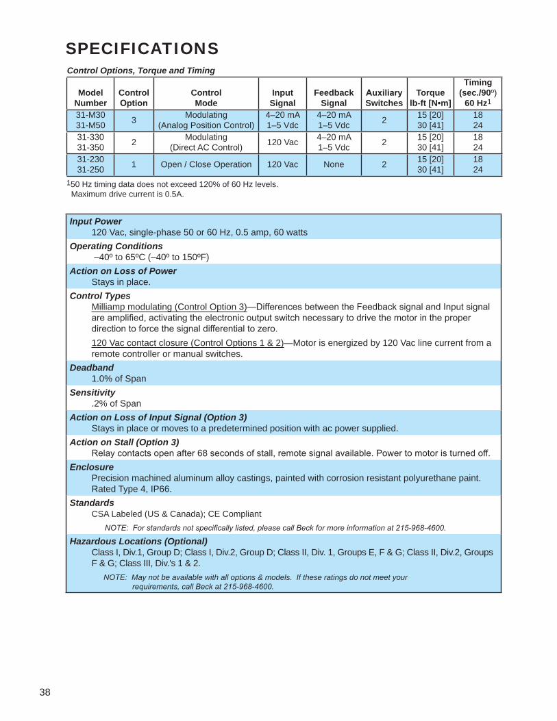
SPECIFICATIONSControl Options, Torque and Timing
ModelNumber
ControlOption
ControlMode
InputSignal
FeedbackSignal
AuxiliarySwitches
Torquelb-ft [N•m]
Timing(sec./90º)
60 Hz1
31-M3031-M50 3 Modulating
(Analog Position Control)4–20 mA1–5 Vdc
4–20 mA1–5 Vdc 2 15 [20]
30 [41]1824
31-33031-350 2 Modulating
(Direct AC Control) 120 Vac 4–20 mA1–5 Vdc 2 15 [20]
30 [41]1824
31-23031-250 1 Open / Close Operation 120 Vac None 2 15 [20]
30 [41]1824
150 Hz timing data does not exceed 120% of 60 Hz levels. Maximum drive current is 0.5A.
Input Power 120 Vac, single-phase 50 or 60 Hz, 0.5 amp, 60 wattsOperating Conditions –40º to 65ºC (–40º to 150ºF)Action on Loss of Power Stays in place.Control Types Milliamp modulating (Control Option 3)—Differences between the Feedback signal and Input signal
are amplified, activating the electronic output switch necessary to drive the motor in the proper direction to force the signal differential to zero.
120 Vac contact closure (Control Options 1 & 2)—Motor is energized by 120 Vac line current from a remote controller or manual switches.
Deadband 1.0% of SpanSensitivity .2% of SpanAction on Loss of Input Signal (Option 3) Stays in place or moves to a predetermined position with ac power supplied.Action on Stall (Option 3) Relay contacts open after 68 seconds of stall, remote signal available. Power to motor is turned off.Enclosure Precision machined aluminum alloy castings, painted with corrosion resistant polyurethane paint.
Rated Type 4, IP66.Standards CSA Labeled (US & Canada); CE Compliant NOTE: For standards not specifically listed, please call Beck for more information at 215-968-4600.
Hazardous Locations (Optional) Class I, Div.1, Group D; Class I, Div.2, Group D; Class II, Div. 1, Groups E, F & G; Class II, Div.2, Groups
F & G; Class III, Div.'s 1 & 2. NOTE: May not be available with all options & models. If these ratings do not meet your requirements, call Beck at 215-968-4600.

39
Basic Actuator Mounting Option AYoke Mounting with coupling
connection and mechanical stop
Mounting Option BBracket mounting with crank arm assembly and mechanical stop
Mounting Option CBasic actuator with crank arm
assembly and mechanical stop
Mounting Option DBasic actuator with mechanical stop
*STANDARD BRACKET CAN BE SUPPLIED WITHOUT HOLES OR HOLE PATTERN SHOWN.
Mechanical Specifications
1 5/32[29]
2 1/32[52]
14 29/32 [379]7 1/16 [179] CLEARANCE
REQUIRED FORCOVER REMOVAL
6 45/64[170]
DIA..9800[24.892]
.7500[19.050]
DIA.
CONTROL CALIBRATION
17°
17°
HANDWHEEL
ACCESS
33 15/32
3 5/8
SPACED ON 3 3/8 [86] B.C.TYP. (3) PLACES HOLES EQUALLY3/8-16 UNC-2B x 7/8 [22] DEEPMOUNTING HOLES
3/4" N.P.T. SIGNALWIRE CONDUIT
ENTRANCE
ENTRANCEWIRE CONDUIT
3/4" N.P.T. POWER
3 3/16[81]
4 5/16[110]
[76][88]
[92]
1 7/8
31/32
3 3/4
4 7/8
[25]
[48]
[95]
[124]
CRANK ARM RADIUS1 1/2- 5 1/8
ADJUSTABLE
5/16-24 THREADx .750 [19] DEEP
P
NEP0
0NE
S
SED
OCL
DE O CL
RADIUS
*11/32 [9] DIA. HOLETHRU, TYP. (4) PLACES(FOR 5/16 BOLTS)
1 3/8[35]
[38]-[130]
[144]5 11/16
4 1/2 [114]
1 1/2 [38]*
2 1/4 [57]3 [76]*
Beck Drive Model Approx. Wt. lbs [kg] Max. Overhung Load lbs [kg]Group 31 36 [16] 500 [227]
Drives may be mounted in any orientation.All dimensions are subject to change. Request certified dimensional drawings for the drives you select.
C (LINKAGENOT INCLUDED)L
2 7/16
6 1/2
4[165]
[102]
5 1/8[130]
[62]
3 1/4*[83]
9/16*[14]
3 15/32 [88] REF.
4 5/16[110]REF.
BOLT HOLE PATTERN AND SHAFTTHROUGH HOLE DIMENSION MUSTBE SPECIFIED PER APPLICATION
USE 5/16 [8] MAX. MATERIALTHICKNESS FOR MOUNTING BRACKET. 1 1/8 [29] DIA.CLEARANCE HOLE REQUIRED FOR SHAFT.
C (LINKAGE NOT INCLUDED)L
2 7/16[62]
USE 5/16 [8] MAX. MATERIAL THICKNESS FOR MOUNTING BRACKET. 1 1/8 [29] DIA. CLEARANCE HOLE REQUIRED FOR SHAFT.
1 [25]
OUTLINE DIMENSION DRAWINGS

40
41
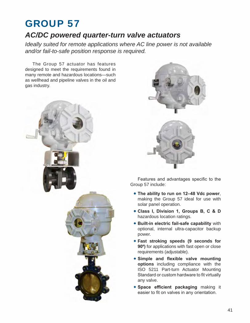
Features and advantages specific to the Group 57 include:
• The ability to run on 12–48 Vdc power, making the Group 57 ideal for use with solar panel operation.
• Class I, Division 1, Groups B, C & D hazardous location ratings.
• Built-in electric fail-safe capability with optional, internal ultra-capacitor backup power.
• Fast stroking speeds (9 seconds for 90⁰) for applications with fast open or close requirements (adjustable).
• Simple and flexible valve mounting options including compliance with the ISO 5211 Part-turn Actuator Mounting Standard or custom hardware to fit virtually any valve.
• Space efficient packaging making it easier to fit on valves in any orientation.
GROUP 57AC/DC powered quarter-turn valve actuators Ideally suited for remote applications where AC line power is not available and/or fail-to-safe position response is required.
The Group 57 actuator has features designed to meet the requirements found in many remote and hazardous locations—such as wellhead and pipeline valves in the oil and gas industry.

42
FEATURESBeck MotorCompact, Reliable Control & Uniquely Fast The compact Beck motor provides powerful, reliable performance.• Never overheats or burns out, even under
demanding modulating control or stalled conditions.
• Starts and stops instantaneously—eliminating deadtime.
• Travels 90 degrees in 9 seconds.• Provides extremely accurate positioning in
modulating applications.• Will not coast or overshoot the desired
position.• Low power draw eliminates the need for
relays. Very efficient when used with the optional, internal backup power supply.
• Maintenance-free with double-lipped, grease-sealed bearings.
Lockable, Electric HandswitchTime-Saving Local Operation Valves may be operated at their individual locations with the built-in, lockable, electric Handswitch. This saves t ime during installation and troubleshooting, allowing online adjustments to be made quickly and easily by bypassing the electronics in the actuator and control system. The Handswitch also serves as an electrical backup in the event of control system failure. The Handswitch may also be locked in the AUTO position to prevent local operation.
Over-travel Limit Switches & Auxiliary Switches Two over-travel protection limit switches are provided and up to four additional auxiliary switches are available as an option. Switch features include:• Rated for a minimum of 6 A at 120 Vac to
ensure long life.• Field-adjustable to operate at any point in the
actuator’s travel range.• May initiate secondary functions or provide
remote indication of actuator position. • Eliminates unreliable and maintenance-
intensive proximity switches.
Group 57 Actuator Component Locations
Handswitch forManual Operation(Power Required)
1" N.P.T. ConduitEntrances(4 Places)
Hand Crank forManual Operation(Power Not Required)
Threaded FrontCover (Terminals,Optional ViewingWindow forFeedback Display)Nameplate
Output Shaft
Lugs for Easy Cover Removal
Threaded Top Cover(Motor, DCM, Switches)

43
Feedback Display (optional)Actuator position at a glance The feedback display is an illuminated, numerical readout showing the actuator's position as a percentage of full travel. The display is viewed through a tempered glass window in the terminal compartment. Three LEDs are visible through the window. Two configurable LEDs light at either end of actuator travel—a red LED and a green LED. A yellow LED lights when the actuator is moving toward either end of travel.
Drive TrainPower and Durability that Maximize Reliability and Minimize Maintenance Beck’s durable gear train maintains accurate, consistent valve positioning even under the demanding conditions of an active control loop.• Gear trains are constructed of heat-treated
alloy steels and ductile iron.• Efficient gearing essentially eliminates
wear-induced backlash and positioning inaccuracies.
• Durable design provides up to 4 days of protection against intermittent or extended accidental stalls.
• Integral self-locking mechanism ensures that actuators hold a minimum of 200% of rated torque with the motor de-energized.
Hand crankManual Control Without Declutch An easy-to-turn Hand crank is incorporated into the Group 57 design to allow manual operation during installation or power outages.• The hand crank can be used to move valves
to any position smoothly and easily under full load conditions.
• Mechanical stops prevent manual overtravel.
HousingSuperior Protection and ConvenientAccess to Components Beck actuators feature a cast aluminum body with compartments to protect components from moisture and dirt, and allow easy access for installation and calibration.• Precision-machined aluminum alloy castings
with corrosion-resistant poly-urethane paint provide a rugged, dust-tight, weatherproof Type 4X enclosure.
• Specifically designed for use in Hazardous classified locations—Class I, Division 1, Groups B, C & D.
• The top compartment protects the motor, electronics and switches. A separate, sealed compartment protects the terminals and display.
• Gasketed, precision-machined, threaded covers provide extra protection for harsh environments.
• Output and hand crank shafts use double-lip seals to ensure lifelong protection from harsh environments.
Mounting VersatilityCan be Mounted in any Orientation for Greater Installation Flexibility Group 57 actuators are lubricated in such a way that they may be mounted in any convenient position. This flexibility allows actuators to be installed in hard-to-fit locations. Mounting orientation is limited only by the accessibility of the housing compartments.

44
SAMPLE WIRING DIAGRAM & SPECIFICATIONS
DEMANDANALOG
S1
S2
S3
S4
UNUSED
UNUSED
UNUSED
TRAVELLIMITS
DO NOTCONNECT
STATUS OUTPUTRELAY 3
HANDSWITCH AUTOINDICATION28VDC MAX100MA MAX
STATUS OUTPUTRELAY 2
STATUS OUTPUTRELAY 1 (ALARM STATUS)
POSITIONFEEDBACK
TORQUESENSING
(OPTIONAL)
OUTPUT SHAFTPOSITION SENSOR
DIGITAL COM
STOPCCW
CWCOM
STOPCCW
CW
NEUT
PICUNUSED
MOTOR
DCM
AC NEUTRAL OR DC (+)
AC LINE OR DC (–)
DRYCONTACTCONTROLOVERRIDE
INPUTS
PULSED VACCONTROLOVERRIDE
INPUTS
DIGITAL BUS (+)DIGITAL BUS (–)
REFER TO ACTUATORNAMEPLATE FORVOLTAGE RATING
AUXILIARYSWITCHES
(+)(–)
(+)(–)
STOP
CCWCW
CCW
CW
AUTO
AUTO
HANDSWITCH
36
5
7
9
11
4
6
8
10
41
3837
15
141312
4039
272625
242322
2120
35
343332
31302928
191817
16
3
2
1
}
}
G G
Power 12–30 Vdc (standard). Optional variants: Extended range DC (12–48 Vdc); AC transformers (120, 208, 240, 380,
415, 480, 575 Vac).Torque Output 120 lb-ft (162.7 N•m).Stroke Timing 9 seconds per 90⁰ (configurable for slower speeds).Positioning Resolution (Minimum Step Size) 0.1° typical. Configurable from 0.1° to 2.25°.Weight Approximately 59 lbs. (27 kgs.).Certifications Ordinary & Hazardous Locations available: Class I, Division 1, Groups B, C & D and Class II, Division 1, Groups
E,F & G. Enclosure ratings: Type 4X; IP66/IP68 at 3 meters for 48 hours.Environmental Temperature Rating -50ºC to 85ºC (-58⁰F to 185⁰F) (may vary depending on options).Control Input 4–20 mA signal or ac/dc pulses.Communication Interfaces HART and Modbus RTU (standard); Modbus TCP (optional)Configuration Options Local pushbuttons, RS-232 Serial command port, Device Description (DD) based HART tools, Modbus.Modulation Duty 100% continuous duty with no limitations.Mounting Orientations Actuator may be mounted in any orientation without restrictions.Manual Operation Hand crank (no power required) and Handswitch (power required).Switches and Relays (2) cam-operated over-travel protection switches (standard); up to (4) Form C auxiliary, cam-operated switches
(optional); (1) SS alarm; (2) programmable SS SPST relays (standard) or (2) mechanical DPDT relays (optional); status relay (standard).
Wiring and Termination Easy access, screw-type terminals accept up to 12 AWG wire.Hard Stops Internal, fixed (standard); external adjustable hard stops (optional).Status Indications Configurable LEDs (red, green and yellow) visible through optional terminal compartment window; digital numeric LED position display available (only if ordered with optional terminal compartment window).External Position Feedback Signal 4–20 mA or 1–5 Vdc signal (standard).Backup Power Supply (Optional) An internal backup supply utilizing ultra-capacitors to provide “go-to-position” response upon power loss;
maximum operating temperature limitations apply.Valve Mounting Hardware (Optional) ISO 5211 compatible hardware or custom hardware.
45
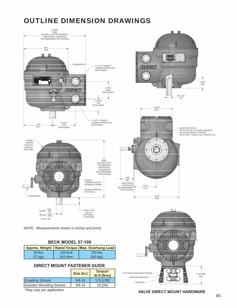
OUTLINE DIMENSION DRAWINGS15 9/32”
[388](ALLOW 2” [51] FOR REMOVAL,
ADDITIONAL CLEARANCERECOMMENDED FOR ACCESS)
Ø11”[279]
1” N.P.T. CONDUITPOWER CONNECTIONBOTH SIDES
1” N.P.T. CONDUITPOWER CONNECTIONBOTH SIDES
HANDSWITCH
4 5/16”[109]
BOTH SIDES
5 19/32”[142]
BOTH SIDES7 1/8”[181]
2 21/32”[76]
BOTH SIDES
2 9/32”[58]
Ø1 1/16”[27]
MOUNTING HOLES3/8-16 UNC-2B X 5/18 MIN. [16] DEEP(8) HOLES EQUALLY SPACEDON A 5.000 ± .015 [127.00 ± 0.38] DIA. B.C.
7 29/32”[201]
11 1/8”[282]
5 9/16”[141]
(ADDITIONAL CLEARANCE
RECOMMENDED FOR ACCESS)
3 3/8”[86]
1 23/32” ± 1/8”[44 ± 3]
(OPTIONAL:2 19/32” [66])
SHAFT DIA.
+.001-.000+.025-.000
Ø1.500”
38.100
COVER,TERMINAL BLOCKEXTERNAL WIRING
VIEWING WINDOW(OPTIONAL)
COVER,DIGITAL
CONTROL MODULE,
SWITCHES
HANDWHEEL
14”[356]
(ALLOW 6” [152] FOR REMOVAL,
ADDITIONAL CLEARANCE
RECOMMENDED FOR ACCESS)
4 7/16” MIN.[113]
ACTUATOR MOUNTING SCREWS
MOUNTING BRACKET
COUPLING
VALVE DIRECT MOUNT HARDWARE
BECK MODEL 57-109Approx. Weight Rated Torque Max. Overhung Load
59 lbs.27 kgs.
120 lb-ft163 N•m
750 lbs.340 kgs.
DIRECT MOUNT FASTENER GUIDESize (in.) Torque*
lb-ft [N•m]Coupling Screws 5/8-18 170 [230]Actuator Mounting Screws 3/8-16 25 [34]*May vary per application.
NOTE: Measurements shown in inches and [mm].
46

47
GROUP 75COMPACT ROTARY ACTUATOR Mounting flexibility combined with a highly compact design make this actuator ideal for all types of small rotary valve and Windbox damper applications.
Scanfor G75Video
The Beck Group 75 actuator has an evolutionary design that combines the performance, reliability and control advantages of Beck actuators with an extremely efficient and flexible form factor. The design is smaller and lighter than the Group 11 and more robust than the Group 31. It also incorporates technologies that allow for an optional low temperature version rated for –50°C (–58°F) or a high temperature version rated for 120°C (248°F)—exceeding Beck's standard rating of 85°C (185°F) for the Group 11 and 65°C (150°F) for the Group 31. The high temperature capabilities and efficient, flexible packaging make the Group 75 ideal for space restricted, hot environments typical of boiler windbox applications. It is also well-suited for small rotary valve applications in tight spaces. This actuator shares electronics and
firmware with existing Beck products. This interchangeability of
electronics keeps critical spare parts common with existing Beck
actuators. It also means that all the latest configuration, setup and diagnostic
features are available as well.

48
Beck MotorPrecise, Reliable Control Together with Beck's control electronics and rugged gear train, Beck motors provide the precise, reliable positioning required for modern control loops.• Never overheats or burns out—even under
demanding modulating control or stalled conditions.
• Reaches full speed and torque in less than 50 milliseconds and stops within 25 milliseconds; eliminating deadtime.
• Provides extremely accurate positioning in modulating applications.
• Will not coast or overshoot the desired position.
• Low current draw (0.16 A to 0.40 A) and low power consumption permit the use of uninterruptible power supplies; also eliminates the need for relays.
• Maintenance-free with double-lipped grease-sealed bearings.
FEATURESElectric HandswitchTime-Saving Local Operation Dampers or valves may be operated at their individual locations with the built-in electric Handswitch. This saves time during installation and troubleshooting, allowing online adjustments to be made quickly and easily bypassing the electronics in the actuator and control system. The Handswitch also serves as an electrical backup in the event of control system failure.
Auxiliary and Over-travel Limit Switches Two over-travel protection limit switches are provided. Up to four auxiliary switches are available. Switch features:• SPDT switches rated for a minimum of 6 A at
120 Vac, (three times maximum motor current for most models) to ensure long life.
• Field-adjustable to operate at any point in the actuator's travel range.
• May initiate secondary functions or provide remote indication of actuator position.
• Eliminates unreliable and maintenance-intensive proximity switches.
Position Sensing Device - Film Potentiometer
Switches
HandwheelHandswitch
Wiring Terminal Block(opposite side)
Motor Housingand Gear Train
Digital ControlModule (DCM)
Model 75-109 Components
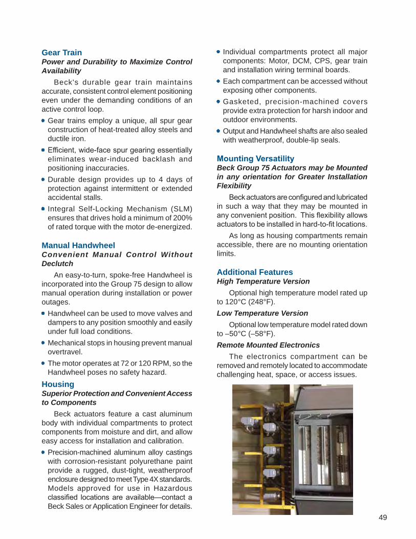
49
Gear TrainPower and Durability to Maximize Control Availability Beck's durable gear train maintains accurate, consistent control element positioning even under the demanding conditions of an active control loop.• Gear trains employ a unique, all spur gear
construction of heat-treated alloy steels and ductile iron.
• Efficient, wide-face spur gearing essentially eliminates wear-induced backlash and positioning inaccuracies.
• Durable design provides up to 4 days of protection against intermittent or extended accidental stalls.
• Integral Self-Locking Mechanism (SLM) ensures that drives hold a minimum of 200% of rated torque with the motor de-energized.
Manual HandwheelConvenient Manual Control Without Declutch An easy-to-turn, spoke-free Handwheel is incorporated into the Group 75 design to allow manual operation during installation or power outages.• Handwheel can be used to move valves and
dampers to any position smoothly and easily under full load conditions.
• Mechanical stops in housing prevent manual overtravel.
• The motor operates at 72 or 120 RPM, so the Handwheel poses no safety hazard.
HousingSuperior Protection and Convenient Access to Components Beck actuators feature a cast aluminum body with individual compartments to protect components from moisture and dirt, and allow easy access for installation and calibration.• Precision-machined aluminum alloy castings
with corrosion-resistant polyurethane paint provide a rugged, dust-tight, weatherproof enclosure designed to meet Type 4X standards. Models approved for use in Hazardous classified locations are available—contact a Beck Sales or Application Engineer for details.
• Individual compartments protect all major components: Motor, DCM, CPS, gear train and installation wiring terminal boards.
• Each compartment can be accessed without exposing other components.
• Gasketed, precision-machined covers provide extra protection for harsh indoor and outdoor environments.
• Output and Handwheel shafts are also sealed with weatherproof, double-lip seals.
Mounting VersatilityBeck Group 75 Actuators may be Mounted in any orientation for Greater Installation Flexibility Beck actuators are configured and lubricated in such a way that they may be mounted in any convenient position. This flexibility allows actuators to be installed in hard-to-fit locations. As long as housing compartments remain accessible, there are no mounting orientation limits.
Additional FeaturesHigh Temperature Version Optional high temperature model rated up to 120°C (248°F).Low Temperature Version Optional low temperature model rated down to –50°C (–58°F).Remote Mounted Electronics The electronics compartment can be removed and remotely located to accommodate challenging heat, space, or access issues.

50
CONTROL OPTIONS & SAMPLE WIRING DIAGRAMSDiagrams are functional—customer wiring may vary. Certified wiring diagrams can be provided for the drive you select.
Option 6, Modulating Direct AC Control with Contactless Position Sensor (CPS) Customer must supply three wires to directly control the drive motor direction: One 120 Vac line to run CW (terminal 12), one 120 Vac line to run CCW (terminal 16), and one neutral (terminal 2). Customer must supply two additional wires to power the “2-wire” type CPS (see your specific wiring diagram or the typical wiring diagram below).
Option 9, Modulating Digital Position Control with Potentiometer Position Sensing The Beck DCM positions the drive in proportion to an input current or voltage signal, and the Film Potentiometer provides integral feedback for the DCM. A 4–20 mA position feedback signal is available for remote indication. Foundation Fieldbus is also available. The DCM may be used to provide pre-determined positioning of the drive upon loss of input control signal.

51
Option 5, Modulating Direct AC Control with Potentiometer Position Sensing Customer must supply three wires to directly control the drive motor direction: One 120 Vac line to run CW (terminal 12), one 120 Vac line to run CCW (terminal 16), and one neutral (terminal 2). The position feedback potentiometer connections are available at terminals 32 (CW), 33 (wiper), and 34 (CCW).
Option 3, Open / Close Direct AC Control Customer must supply three wires to directly control the drive motor direction: One 120 Vac line to run CW (terminal 12), one 120 Vac line to run CCW (terminal 16), and one neutral (terminal 2).
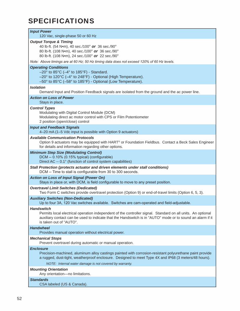
52
SPECIFICATIONSInput Power 120 Vac, single-phase 50 or 60 HzOutput Torque & Timing 40 lb-ft. (54 N•m), 40 sec./100° or 36 sec./90° 80 lb-ft. (108 N•m), 40 sec./100° or 36 sec./90° 80 lb-ft. (108 N•m), 24 sec./100° or 22 sec./90°Note: Above timings are at 60 Hz; 50 Hz timing data does not exceed 120% of 60 Hz levels.
Operating Conditions –20° to 85°C (–4° to 185°F) - Standard. –20° to 120°C (–4° to 248°F) - Optional (High Temperature). –50° to 85°C (–58° to 185°F) - Optional (Low Temperature).Isolation Demand Input and Position Feedback signals are isolated from the ground and the ac power line.Action on Loss of Power Stays in place.Control Types Modulating with Digital Control Module (DCM) Modulating direct ac motor control with CPS or Film Potentiometer 2 position (open/close) controlInput and Feedback Signals 4–20 mA (1–5 Vdc input is possible with Option 9 actuators)Available Communication Protocols Option 9 actuators may be equipped with HART® or Foundation Fieldbus. Contact a Beck Sales Engineer
for details and information regarding other options.Minimum Step Size (Modulating Control) DCM -- 0.10% (0.15% typical) (configurable) Direct AC -- 0.1° (function of control system capabilities)Stall Protection (protects actuator and driven elements under stall conditions) DCM -- Time to stall is configurable from 30 to 300 seconds.Action on Loss of Input Signal (Power On) Stays in place or, with DCM, is field configurable to move to any preset position.Overtravel Limit Switches (Dedicated) Two Form C switches provide overtravel protection (Option 9) or end-of-travel limits (Option 6, 5, 3).Auxiliary Switches (Non-Dedicated) Up to four 3A, 120 Vac switches available. Switches are cam-operated and field-adjustable.Handswitch Permits local electrical operation independent of the controller signal. Standard on all units. An optional
auxiliary contact can be used to indicate that the Handswitch is in "AUTO" mode or to sound an alarm if it is taken out of "AUTO".
Handwheel Provides manual operation without electrical power.Mechanical Stops Prevent overtravel during automatic or manual operation.Enclosure Precision-machined, aluminum alloy castings painted with corrosion-resistant polyurethane paint provide
a rugged, dust-tight, weatherproof enclosure. Designed to meet Type 4X and IP68 (3 meters/48 hours). NOTE: Internal water damage is not covered by warranty.
Mounting Orientation Any orientation—no limitations.Standards CSA labeled (US & Canada).

53
OUTLINE DIMENSION DRAWINGS
Actuators may be mounted in any orientation.All dimensions are subject to change. Request certified dimensional drawings for the actuators you select.
FRONT VIEW
1 25/32[45]
1/2[13]
MOUNTING HOLES3/8-16 UNC-2B X 1/2 [13] DEEP
(4) HOLES, EACH SIDE
MOUNTING PLATE(OPTIONAL)
CRANK ARM(OPTIONAL)
MOUNTING HOLES3/8-16 UNC-2B X 1/2 [13] DEEP
(3) HOLES
NAMEPLATE
4 3/4[120]
4 7/8[124]
4 15/32[114]
4 3/16[106]
6 9/32[160]
9 3/32[231]
3/4[19]
2 13/16[71]
4 3/4[120]
SIDE VIEWS
2 5/8[67]
3 3/16[81]
3/16[5]
12 13/16 [326](ALLOW 6" [152] FOR REMOVAL)
1" N.P.T.CONDUIT POWER
CONNECTION
1" N.P.T. CONDUITSIGNAL CONNECTION
HANDSWITCH
MOUNTING HOLES3/8-16 UNC-2B X 1/2 [13] DEEP
(4) HOLES, EACH SIDE LINKAGE CL
6 1/2 [165](2) PLACES
3 [76](2) PLACES
BOTH SIDES
1 3/16 [30](2) PLACESBOTH SIDES
29/32 [23](2) PLACESBOTH SIDES
3 1/2 [89](2) PLACES
BOTH SIDES
HANDWHEEL
LINKAGE CL
COVER,TERMINAL BLOCKEXTERNAL WIRING
COVER, POSITIONSENSING DEVICES
11 1/16 [281](ALLOW 7” [178] FOR REMOVAL)
10 1/8 [257](ALLOW 4” [102] FOR REMOVAL)
CDIM.
Model 75-109

54
OUTLINE DIMENSION DRAWINGS
FRONT VIEW REAR VIEW
1 25/32[45]
1/2[13]
MOUNTING HOLES3/8-16 UNC-2B X 1/2 [13] DEEP
(4) HOLES, EACH SIDE
MOUNTING PLATE(OPTIONAL)
CRANK ARM(OPTIONAL)
MOUNTING HOLES3/8-16 UNC-2B X 1/2 [13] DEEP
(3) HOLES
NAMEPLATE
4 3/4[120]
4 15/32[114]
4 3/16[106]
6 9/32[160]
9 3/32[231]
3/4[19]
2 13/16[71]
4 3/4[120]
LINKAGE CL
MOUNTING HOLES3/8-16 UNC-2B x 1/2 [13] DEEP
(4) HOLES, BOTH SIDES
COVER,TERMINAL BLOCK
EXTERNAL WIRING
3[76]
BOTH SIDES
3 1/2[89]
BOTH SIDES
9 21/32[245]
(ALLOW 1” [25] FOR REMOVAL)
1 3/16[30]BOTH SIDES
HANDSWITCH
29/32[23]BOTH SIDES
LINKAGE CL
10 1/8 [257](ALLOW 4" [102] FOR REMOVAL)
11 1/16 [281](ALLOW 7" [178] FOR REMOVAL)
"C"
COVER, POSITIONSENSING DEVICES
HANDWHEEL
2 1/8[54]
1 1/6[27]
4 29/32[125]
3/4" N.P.T CONDUITSIGNAL CONNECTION
3/4" N.P.T CONDUITPOWER CONNECTION
Model 75-106/-105/-103
SIDE VIEWS

55
OPTIONAL CRANK ARM DETAIL (Crank Arm 10-3491-05 shown)
CRANK ARMSCREW
R
L
T
R2
ROD END SCREW
ROD END
WASHERS (2)
WEDGE
ROD ENDLOCK NUT
BOTTOM MOUNTING LOCATIONS
MOUNTING HOLES3/8-16 UNC-2B x 1/2 [13] DEEP
(4) HOLES((3) PLACES—BOTTOM & 2 SIDES)
1 3/4 [44](2) PLACES
1 3/4 [44](2) PLACES
1 3/16 [30](2) PLACES
3 [76](2) PLACES
4 [102](2) PLACES
4 [102](2) PLACES
7 [178](2) PLACES
3/8 [10](2) PLACES
1/2 [13]EACH CORNER
1/2 [13]EACH CORNER
MOUNTING HOLESØ 13/32 [10](2) PLACES
MOUNTING HOLESØ 13/32 [10](2) PLACES
WITH OPTIONALMOUNTING PLATE
Model 75
Drives may be mounted in any orientation.All dimensions are subject to change. Request certified dimensional drawings for the drives you select.
MODEL INFORMATIONMax.
Torque(lb-ft)[N•m]
Optional Crank Arms and Rod Ends OutputShaft Dia.(in)[mm]
Approx.Weight
(lbs)[kgs]
MaximumOverhung
Load(lbs)[kgs]
Crank ArmPart No.
Crank ArmRadius (adj.)"R" (in)[mm]
Crank ArmRadius "R2"
(in)[mm]
Linkage Center toFront Mtg. Bosses
“C” (in)[mm]
Rod EndLength "L"
(in)[mm]
Rod EndInternal Thread
"T" (in)[mm]80
[108] 10-3491-05 1 1/2–5 1/8[38–130]
6 3/32[155]
1 27/32–1 7/8[47–48]
2 1/8[54]
1/2-20 x 1 3/16 [30]
3/4[19]
46[21]
750[340]
80[108] 10-3491-52 1 1/2–4
[38–102]4 11/16[119]
1 21/32–1 15/16[42–49]
2 1/8[54]
1/2-20 x 1 3/16 [30]
3/4[19]
46[21]
750[340]
40[54] 10-3492-02 1 1/2–5 1/8
[38–130]5 11/16[144]
1 11/32–1 3/4[34–44]
1 3/8[35]
5/16-24 x3/4 [19]
3/4[19]
46[21]
500[227]
RECOMMENDED SCREW TORQUESScrew Size
(in)Torque
(lb-ft)[N•m]Crank Arm
Part No.Crank Arm
Screw Size (in)Torque
(lb-ft)[N•m]Rod End
Screw Size (in)Torque
(lb-ft)[N•m]Rod End LockNut Size (in)
Torque(lb-ft)[N•m]
Cover Screw 1/4-20 6 [8] 10-3491-05 1/2-13 75 [102] 1/2-13 35 [47] 1/2-13 55 [75]
Motor Screw 1/4-20 6 [8] 10-3491-52 3/8-24 50 [68] 1/2-13 35 [47] 1/2-13 55 [75]
Mounting PlateScrew (optional) 3/8-16 20 [27] 10-3492-02 5/16-24 20 [27] 5/16-24 20 [27] 5/16-24 20 [27]
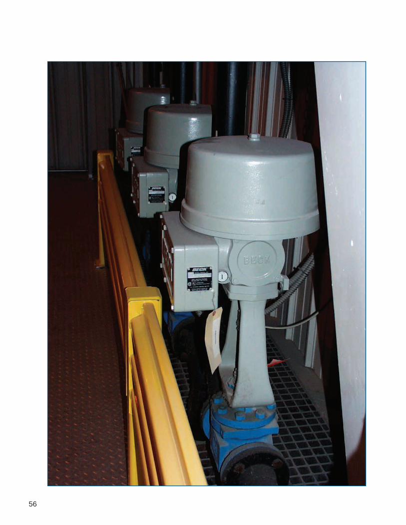
56
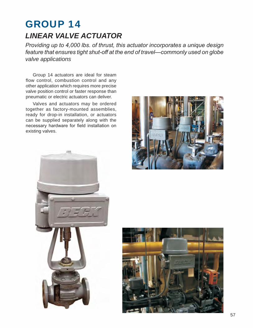
57
GROUP 14LINEAR VALVE ACTUATOR Providing up to 4,000 lbs. of thrust, this actuator incorporates a unique design feature that ensures tight shut-off at the end of travel—commonly used on globe valve applications
Group 14 actuators are ideal for steam flow control, combustion control and any other application which requires more precise valve position control or faster response than pneumatic or electric actuators can deliver. Valves and actuators may be ordered together as factory-mounted assemblies, ready for drop-in installation, or actuators can be supplied separately along with the necessary hardware for field installation on existing valves.

58
Position Sensing Device (CPS)
FEATURES
Switches
Digital ControlModule (DCM) and Wiring Terminal Board
Tight Seater™Coupling
Model 14 Components
Handwheel
Beck Actuator MotorPrecise, Reliable Control Together with Beck’s control electronics and rugged gear train, Beck motors provide the precise, reliable positioning required for modern control loops.• Never overheats or burns out, even under
demanding modulating control or stalled conditions.
• Reaches full speed and torque in less than 50 milliseconds and stops within 25 milliseconds, eliminating deadtime.
• Provides extremely accurate positioning in modulating applications.
• Will not coast or overshoot the desired position.
• Low current draw of 0.33 A to 1.5 A, and therefore low power consumption, eliminates the need for relays and permits the use of uninterruptible power supplies.
Electric HandswitchTime-Saving Local Operation Valves may be operated at their individual locations with the built-in electric Handswitch. This saves time during installation and troubleshooting, allowing online adjustments to be made quickly and easily by bypassing the electronics in the actuator and control system. The Handswitch also serves as an electrical backup in the event of control system failure.
Auxiliary and Over-travelLimit Switches Two dedicated over-travel protection limit switches (RET, EXT) and two form C auxiliary switches (S1, S2) are provided. Two additional auxiliary switches (S3, S4) are optionally available.• SPDT switches rated for a minimum of 6 A at
120 Vac, (three times maximum motor current for most models) to ensure long life.
• Field-adjustable to operate at any point in the actuator’s travel range.
• May initiate secondary functions or provide remote indication of actuator position.
• Eliminates unreliable and maintenance- intensive proximity switches.
Drive TrainPower and Durability toMaximize Control Availability Beck’s durable gear train maintains accurate, consistent control element positioning even under the demanding conditions of an active control loop.• Gear trains use an all spur gear construction
of heat-treated alloy steels and ductile iron.• Efficient, wide-face spur gearing essentially
eliminates wear-induced backlash and positioning inaccuracies.
Motor Housingand Gear Train

59
Factory Mounted Assemblies Beck will supply Group 14 actuators mounted to valves, fully tested and ready for simple drop in installation. Group 14 actuators are generally furnished with a standard cast yoke for globe valves with boss sizes up to 3 3/4” [95 mm]. When the Group 14 actuator is installed on valves with boss sizes exceeding 3 3/4” [95 mm], special yokes are built to provide sturdy, deformation-free assemblies.
Tight-Seater™ The unique Tight-Seater™ coupling incorporated into every unit provides positive seating of the valve plug for tight shutoff. This device compresses the plug into the seat of the valve until the actuator reaches its end of travel, for a seating force at least equal to the rated thrust of the valve. A patented self-locking mechanism holds the output shaft in position even when the motor is de-energized.
One-Step Valve Travel Adjustment Beck’s unique Calibar index allows fast and easy travel adjustment because position feedback devices and over-travel limit switches are all adjusted at the same time. Intermediate auxiliary switches are automatically adjusted to the same percentage of full travel.
TIGHT-SEATERCOUPLING
TM
DIRECTION OFCOMPRESSION
VALVE STEM CONNECTION (MOVEABLE COUPLING TO
COMPRESS DISKS)
ACTUATOR OUTPUT SHAFTCONNECTION
TIGHT-SEATER HOUSING
LINEAR THRUST DISKS(NUMBER OF DISKSVARIES WITH RATEDTHRUST OF VALVE)
THREADED RING TO CONTAIN MOVEABLECOUPLING
• Integral self-locking mechanism ensures that drives hold a minimum of 200% of rated torque with the motor de-energized.
Manual HandwheelConvenient Manual Control Without Declutch An easy-to-turn, spoke-free Handwheel allows manual operation during installation or power outages.• Moves valves to any position smoothly and
easily, even under full load conditions.• Mechanical stops in housing prevent manual
overtravel.• The motor operates at 60 or 72 RPM, so the
Handwheel poses no safety hazard.
HousingSuperior Protection and ConvenientAccess to Components Beck actuators feature a cast aluminum body with individual compartments to protect components from moisture and dirt, and allow easy access for installation and calibration.• Precision-machined aluminum alloy castings
with corrosion-resistant poly-urethane paint provide a rugged, dust-tight, weatherproof enclosure.
• Individual compartments protect all major components.
• Each compartment can be accessed without exposing other components.
• Gasketed, precision-machined covers provide extra protection for harsh indoor and outdoor environments.
• Output and Handwheel shafts are also sealed with weatherproof, double-lip seals.
Mounting VersatilityBeck Actuators can be Mounted in anyOrientation for Greater Installation Flexibility Beck actuators are configured and lubricated in such a way that they may be mounted in any convenient position. This flexibility allows actuators to be installed in hard-to-fit locations.
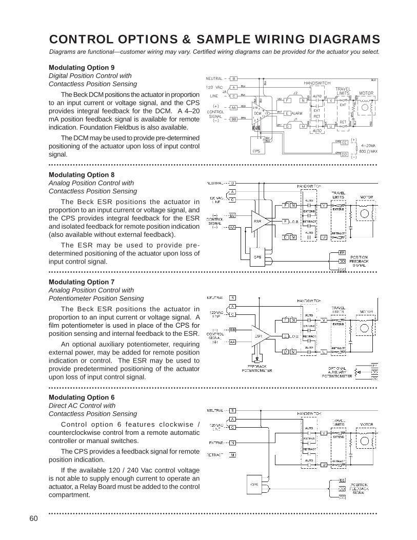
60
CONTROL OPTIONS & SAMPLE WIRING DIAGRAMSDiagrams are functional—customer wiring may vary. Certified wiring diagrams can be provided for the actuator you select.
Modulating Option 9Digital Position Control withContactless Position Sensing The Beck DCM positions the actuator in proportion to an input current or voltage signal, and the CPS provides integral feedback for the DCM. A 4–20 mA position feedback signal is available for remote indication. Foundation Fieldbus is also available. The DCM may be used to provide pre-determined positioning of the actuator upon loss of input control signal.
Modulating Option 8Analog Position Control withContactless Position Sensing The Beck ESR positions the actuator in proportion to an input current or voltage signal, and the CPS provides integral feedback for the ESR and isolated feedback for remote position indication (also available without external feedback). The ESR may be used to provide pre-determined positioning of the actuator upon loss of input control signal.
Modulating Option 7Analog Position Control withPotentiometer Position Sensing The Beck ESR positions the actuator in proportion to an input current or voltage signal. A film potentiometer is used in place of the CPS for position sensing and internal feedback to the ESR. An optional auxiliary potentiometer, requiring external power, may be added for remote position indication or control. The ESR may be used to provide predetermined positioning of the actuator upon loss of input control signal.
Modulating Option 6Direct AC Control withContactless Position Sensing Control opt ion 6 features clockwise / counterclockwise control from a remote automatic controller or manual switches. The CPS provides a feedback signal for remote position indication. If the available 120 / 240 Vac control voltage is not able to supply enough current to operate an actuator, a Relay Board must be added to the control compartment.

61
Modulating Option 5Direct AC Control withPotentiometer Position Sensing Actuated in clockwise or counterclockwise from a remote location or manual switches, this configuration includes a 1000 ohm film potentiometer for remote feedback. An optional auxiliary 1000 ohm potentiometer can be added as an additional remote position indication. If the available 120 / 240 Vac control voltage is not able to supply enough current to operate an actuator, a Relay Board must be added to the control compartment.
Multi-Position Option 4Direct AC Control with Cam-OperatedSwitches to Stop Drive Travel Option 4 incorporates adjustable cam-operated switches to stop the actuator in 6 positions (two end-of-travel, four intermediate positions), or 3 positions (one intermediate position). 4-position and 5-position control can also be attained using a different number of switches. Standard end-of-travel switches have extra contacts that can be used for external signaling or interlocking. Configuration shown: BASIC 3-position.
Open / Close Option 3Direct AC Control For simple open / close operation, Option 3 includes two limit switches, which stop the actuator at each end of travel and may also be used for external signaling.
Other operating voltages available All of the options described on this page and the previous page are available for 240 Vac operation instead of 120 Vac operation.
Auxiliary Switch Terminals Auxiliary switches may be added for control or annunciation functions. Switches are rated at 6 A 120 Vac. They may be factory-set or field-adjusted to operate at any point in the drive’s travel.
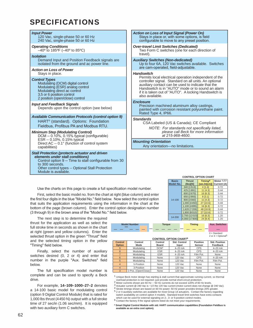
62
SPECIFICATIONS
1 Unique Beck motor design has starting & stall current that approximate running current, so thermal overload protection is not required--just provide normal short-circuit protection.2 Motor currents shown are 60 Hz -- 50 Hz currents do not exceed 120% of 60 Hz levels.3 Actuator current @ 240 Vac is ~1/2 the 120 Vac current (motor current does not change @ 240 Vac).4 Stroke timings shown are based on 60 Hz power; 50 Hz power provides timings 20% greater.5 2 or 4 auxiliary switches are available for most Group 14 actuators. Contact the factory regarding switch availability on control option 4 models. Standard travel limit switches have extra contacts which can be used for external signaling on 2-, 3- or 5-position control modes.6 Contact the factory if the signal options listed do not meet your requirements.
* Smart Digital Control Module with std. HART communication capabilities (Foundation Fieldbus is available as an extra cost option).
Use the charts on this page to create a full specification model number. First, select the basic model no. from the chart at right (blue column) and enter the first four digits in the blue "Model No." field below. Now select the control option that suits the application requirements using the information in the chart at the bottom of the page (brown column). Enter the control option designation number (3 through 9) in the brown area of the "Model No." field below. The next step is to determine the required thrust for the application as well as select the full stroke time in seconds as shown in the chart at right (green and yellow columns). Enter the selected thrust option in the green "Thrust" field and the selected timing option in the yellow "Timing" field below. Finally, select the number of auxiliary switches desired (0, 2 or 4) and enter that number in the purple "Aux. Switches" field below. The full specification model number is complete and can be used to specify a Beck drive. For example, 14–109–1000–27–2 denotes a 14-100 basic model for modulating control (option 9 Digital Control Module) that is rated for 1,000 lbs thrust (4 450 N) output with a full stroke time of 27 sec/in (1.06 sec/mm). It is equipped with two auxiliary form C switches.
0 = Standard2 or 4 = Optional5
BasicModel No.
Thrust(lbs)[N]
Timing4 (sec./in[cm])
Motor 1,2,3Current (A)
14-100
340 [1 513] 4 [1.6] 0.72425 [1 891] 11 [4.3] 0.44600 [2 670] 16 [6.3] 0.44650 [2 893] 8 [3.1] 0.72800 [3 560] 11 [4.3] 0.72
1,000 [4 450] 27 [10.6] 0.441,100 [4 895] 16 [6.3] 0.721,620 [7 209] 48 [18.9] 0.441,800 [8 010] 27 [10.6] 0.72
14-200 2,700 [12 015] 16 [6.3] 1.204,000 [17 800] 24 [9.4] 1.20
Model Number Torque Timing Aux. Switches— — — —— — — — — — — — — — — — —
CONTROL OPTION CHART6
ControlOption
ControlMode
ControlBoard
Std. ControlInput
PositionSensor
Std. PositionFeedback
9 Modulating DCM* 4–20 mA CPS 4–20 mA8 Modulating ESR 4–20 mA CPS 4–20 mA7 Modulating ESR 4–20 mA Film Pot. None6 Modulating None 120 Vac CPS 4–20 mA5 Modulating None 120 Vac Film Pot. Film Pot.4 5-Position None 120 Vac None None4 3-Position None 120 Vac None None3 2-Pos. (Open/Close) None 120 Vac None None
CONTROL OPTION CHART
Input Power 120 Vac, single-phase 50 or 60 Hz 240 Vac, single-phase 50 or 60 HzOperating Conditions –40º to 185ºF (–40º to 85ºC)Isolation
Demand Input and Position Feedback signals are isolated from the ground and ac power line.
Action on Loss of Power Stays in place.Control Types Modulating (DCM) digital control Modulating (ESR) analog control Modulating direct ac control 3,5 or 6 position control 2 position (open/close) controlInput and Feedback Signals Depends upon the control option (see below)
Available Communication Protocols (control option 9) HART® (standard). Options: Foundation
Fieldbus, Profibus PA and Modbus RTU.Minimum Step (Modulating Control) DCM -- 0.10%, 0.15% typical (configurable) ESR -- 0.10%, 0.15% typical Direct AC -- 0.1° (function of control system
capabilities)Stall Protection (protects actuator and driven elements under stall conditions) Control option 9 -- Time to stall configurable from 30
to 300 seconds. Other control types -- Optional Stall Protection
Module is available.
Action on Loss of Input Signal (Power On) Stays in place or, with some options, is field
configurable to move to any preset position.Over-travel Limit Switches (Dedicated) Two Form C switches (one for each direction of
travel).Auxiliary Switches (Non-dedicated) Up to four 6A, 120 Vac switches available. Switches
are cam-operated, field-adjustable.Handswitch Permits local electrical operation independent of the
controller signal. Standard on all units. An optional auxiliary contact can be used to indicate that the Handswitch is in "AUTO" mode or to sound an alarm if it is taken out of "AUTO". A locking Handswitch is also available.
Enclosure Precision machined aluminum alloy castings,
painted with corrosion resistant polyurethane paint. Rated Type 4, IP66.
Standards CSA Labeled (US & Canada); CE Compliant NOTE: For standards not specifically listed, please call Beck for more information at 215-968-4600.Mounting Orientation Any orientation—no limitations.
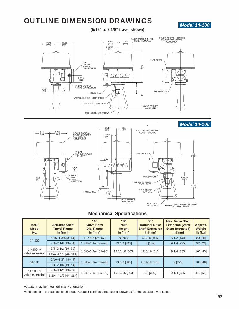
63
(5/16” to 2 1/8” travel shown)
Mechanical Specifications
10
234
HANDSWITCH
NAME PLATE
"A"
COVER, POSITION SENSINGDEVICES AND STROKE
ADJUSTMENTALLOW 8" [203] MIN. FOR
COVER REMOVAL
VALVE BONNETMATCH LINE
1" N.P.T. CONDUITPOWER CONNECTION
1" N.P.T. CONDUITSIGNAL CONNECTION
5/16-18 SOC. SET SCREW
TIGHT-SEATER COUPLING
VARIABLE LENGTH STOP UPPER
HANDWHEEL
"C"
"B"
7 1/2[191]
9 7/32[234]
3 9/16[91]
3 1/2[89]
7[178]
8 1/8[206]
7 3/4[197]
2 15/32[63]
16[406]
1
0
2
3
4
1 3/8 - 3 3/4 [35 - 95] VALVEBOSS DIA. RANGE
5/16-18 SOC.SET SCREW
NAME PLATE
VALVE BONNETMATCH LINE
HANDWHEELTIGHT-SEATER
COUPLING
VARIABLE LENGTHSTOP UPPER
HANDSWITCH
1" N.P.T. CONDUIT POWER CONNECTION
1" N.P.T. CONDUITSIGNAL CONNECTION
COVER, POSITIONSENSING DEVICES AND STROKEADJUSTMENT
7"[178]
3 1/2[89]
3 9/16[90]
9 7/32[234]
7 1/2[191] 2 15/32
[63]
7 3/4[197] ALLOW 8" [203] MIN. FOR
COVER REMOVAL
9 1/4[235]
16[406]
13 1/2[343]
6 11/16[170]
5 1/16[129]
BeckModel
No.
Actuator ShaftTravel Range
in [mm]
"A"Valve BossDia. Range
in [mm]
"B"Yoke
Heightin [mm]
"C"Nominal Drive
Shaft Extensionin [mm]
Max. Valve StemExtension (ValveStem Retracted)
in [mm]
Approx.Weightlb [kg]
14-1005/16–1 3/4 [8–44] 1–2 5/8 [25–67] 8 [203] 4 3/16 [106] 5 1/2 [140] 80 [36]
3/4–2 1/8 [19–54] 1 3/8–3 3/4 [35–95] 13 1/2 [343] 6 [152] 9 1/4 [235] 92 [42]
14-100 w/ valve extension
3/4–3 1/2 [19–89]1 3/8–3 3/4 [35–95] 19 13/16 [503] 12 5/16 [313] 9 1/4 [235] 100 [45]
1 3/4–4 1/2 [44–114]
14-2005/16–1 3/4 [8–44]
1 3/8–3 3/4 [35–95] 13 1/2 [343] 6 11/16 [170] 9 [229] 105 [48]3/4–2 1/8 [19–54]
14-200 w/ valve extension
3/4–3 1/2 [19–89]1 3/8–3 3/4 [35–95] 19 13/16 [503] 13 [330] 9 1/4 [235] 113 [51]
1 3/4–4 1/2 [44–114]
Actuator may be mounted in any orientation.All dimensions are subject to change. Request certified dimensional drawings for the actuators you select.
Model 14-100
Model 14-200
OUTLINE DIMENSION DRAWINGS
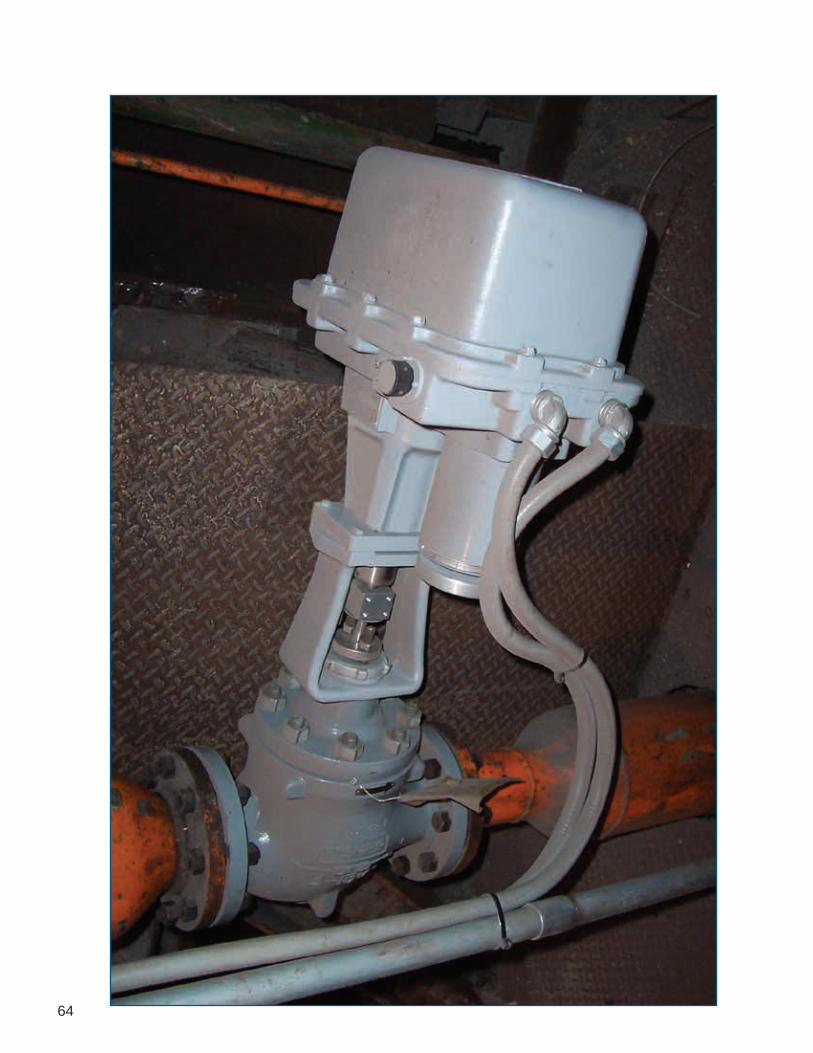
64

65
GROUP 29LINEAR VALVE ACTUATOR Providing up to 6,100 lbs. of thrust, this actuator incorporates a unique design feature that ensures tight shut-off at the end of travel—even in hazardous locations
Ideally suited for process control applications in even the harshest environments, the Group 29 handles valve thrust requirements up to 6,100 lbs. (27 134 N) and is easily mounted on most valves. A ball screw design combined with a new control algorithm and the traditional Beck motor design ensure repeatable modulation as precise as 0.1% of span. The Group 29 is designed for simple installation on almost any globe valve. The design incorporates a rugged, weatherproof body rated for hazardous locations to ensure safe operation in almost any plant environment. Valves and actuators may be ordered together as factory-mounted assemblies, ready for drop-in installation, or actuators can be supplied separately along with the necessary hardware for field installation on existing valves.

66
FEATURES
Digital Control Module (DCM)
Auxiliary Switches Wiring Terminals
Model 29 Components
Beck Actuator Motor The Group 29 utilizes a low current draw, continuous duty motor design. The drive's onboard control electronics (DCM) directly feed the motor windings, thus eliminating external motor starters and controls completely. In addition, the motor will not coast or overshoot and will not overheat—even under continuous modulation.
Electric Handswitch Similar to all Beck actuators, the Group 29 is equipped with an electrical override Handswitch to aid in setup and installation of the actuator independent of external control signals.
Auxiliary Switches Two non-dedicated Form C and Form A switches are standard. These switches are cam-operated and easily adjusted in the field. Wiring connections are provided in the actuator terminal compartment to allow easy access.
Gear Train The Group 29 utilizes a high efficiency gear train designed for high performance, long life and minimum wear. It consists of a combination of precision-cut alloy steel and ductile iron spur gears and a precision ball screw.
Handswitch
Motor Housing
Handwheel
AdjustableMechanical Stop
Position SensingDevice (CPS)
Over-travelLimit Switches

67
Handwheel Group 29 actuators can be manually operated, without power, by a Handwheel attached directly to the motor shaft.
Self-Locking Mechanism (SLM) The SLM is a coupling that transmits motor torque to the gear train, but instantly locks in place when the motor is de-energized; thus preventing back-driving due to dynamic valve load.
Tight-Seater™ This unique device ensures that the valve is positively seated at the closed position.
Housing Beck actuators feature a cast aluminum body with individual compartments to protect components from moisture and dirt, and allow easy access for installation and calibration.• Precision-machined aluminum alloy castings
with corrosion-resistant polyurethane paint provide a rugged, dust-tight, weatherproof Type 4X enclosure.
• Class I, Division 1 and Class II, Division 1 & 2 rated versions are available.
• Gasketed covers provide extra protection for harsh environments.
• Output and Handwheel shafts are sealed with weatherproof, double-lip seals.
Mounting Versatility Beck actuators are configured and lubricated in such a way that they may be mounted in any convenient position. This flexibility allows actuators to be installed in hard-to-fit locations. As long as housing compartments remain accessible, there are no mounting orientation restrictions.
Control & Operating Features In addition to controlling the precise modulation of the actuator, the advanced Digital Control Module (DCM) provides a host of features and functions, including:• Compatibility with common asset management
systems.• Two-way digital communications.• Simple calibration and setup without any
mechanical or electrical adjustments.• Linear, square or 20-segment custom input
signal characterization.• Actuator diagnostics and operating statistics
available locally or remotely.• Configurable action on loss of Demand input
signal.• Stall protection with configurable stall time
setting.

68
CONTROL OPTIONS & SAMPLE WIRING DIAGRAMS
Modulating Option 9Digital Position Control withContactless Position Sensing The Beck DCM positions the actuator in proportion to an input current or voltage signal, and the CPS provides integral feedback for the DCM. A 4–20 mA position feedback signal is available for remote indication. The DCM may be used to provide pre-determined positioning of the actuator upon loss of input control signal.
Open / Close Option 3Direct AC Control For simple open / close operation, Option 3 includes two limit switches, which stop the actuator at each end of travel and may also be used for external signaling.
Diagrams are functional—customer wiring may vary. Certified wiring diagrams can be provided for the actuator you select.

69
SPECIFICATIONSControl Options
Control Option Control Mode Control Input
RangesPosition Sensor
Position Feedback
Aux. Switches (Cust. Use)
9 Modulating (DCM) 4–20 mA, 1–5 Vdc,Digital (fieldbus) CPS 4–20 mA,
Digital (fieldbus) 4
3 2-position (open/close) 120 Vac None None 4
Output Thrust and Timing
Model No. Thrust (lbs.) [N]
Stroke Timing* (sec./in.)[sec./cm]
Min. Stroke Length (in.)[mm]
Max. Stroke Length (in.)[mm]
29-100 1000 [4450] 10 [3.9] 0.50 [13] 2 [51]29-250 1700 [7565] 10 [3.9] 0.50 [13] 2 [51]29-250 2100 [9345] 12.4 [4.9] 0.50 [13] 2 [51]29-250 2700 [12015] 15 [5.9] 0.50 [13] 2 [51]29-600 2100 [9345] 9.4 [3.7] 0.75 [19] 4 [102]29-600 2600 [11570] 11.6 [4.6] 0.75 [19] 4 [102]29-600 3200 [14240] 14 [5.5] 0.75 [19] 4 [102]29-600 4100 [18245] 9.4 [3.7] 0.75 [19] 4 [102]29-600 5000 [22250] 11.6 [4.6] 0.75 [19] 4 [102]29-600 6100 [27145] 14 [5.5] 0.75 [19] 4 [102]
*Timings based on 60Hz power; 50Hz timing = 1.2 x 60Hz timing
Input Power 120 Vac, single-phase 50 or 60 Hz; 240 Vac, single-phase 50 or 60 HzMaximum Current and Power 29-100 -- 0.65A, 78W @ 120 Vac; 0.33A, 78W @ 240 Vac 29-250 -- 1.4A, 170W @ 120 Vac; 0.70A, 170W @ 240 Vac 29-600 -- 2.2A, 260W @ 120 Vac; 1.1A, 260W @ 240 VacOperating Conditions –40º to 185ºF (–40º to 85ºC)Isolation Demand Input and Position Feedback signals are isolated from the ground and the ac power line.Action on Loss of Power Stays in place.Control Types (see chart above) Option 9, Modulating with Digital Control Module (DCM) & Option 3, 2 position (open/close) controlInput and Feedback Signals 4–20 mA, 1–5 Vdc (Option 9 actuators only)Available Communication Protocols (control option 9) HART® (standard). Options: Foundation Fieldbus, Profibus PA and Modbus RTU.Minimum Step (Modulating Control) 0.10% configurable (0.15% default setting)Stall Protection (protects drive and driven elements under stall conditions) Time to stall is configurable from 30 to 300 seconds (option 9 drives).Action on Loss of Input Signal (Power On) Stays in place or, with option 9 drives, is field configurable to move to any preset position.Over-thrust Protection If actuator output thrust exceeds 150% (configurable to 70%) of the drive rating, the motor will shut off (feature can be enabled /
disabled)Over-travel Limit Switches (Dedicated) Two Form C switches (one for each direction of travel) provide over-travel protection.Auxiliary Switches (Non-dedicated) Two Form C and two Form A, rated for 1A, 250 Vac. Switches are field-adjustable.Handswitch Permits local electrical operation independent of the controller signal. Standard on all units. A provided auxiliary contact
can be used to indicate that the Handswitch is in "AUTO" mode or to sound an alarm if it is taken out of "AUTO". A locking Handswitch is also available.
Enclosure Precision-machined, aluminum alloy castings painted with corrosion-resistant polyurethane paint provide a rugged, dust-tight,
weatherproof enclosure. Type 4, 4X; IP66.Standards CSA Labeled (US & Canada); CE Compliant NOTE: For standards not specifically listed, please call Beck for more information at 215-968-4600.Hazardous Locations (Optional) Class I, Div. 1, Groups C & D; Class I, Div. 2, Groups C & D; Class II, Div. 1, Groups E, F & G; Class II, Div. 2, Groups F & G;
Class III, Div. 1 & 2. NOTE: May not be available with all options & models. If ratings do not meet your requirements, call Beck at 215-968-4600.

70
Typical mounting feature will vary per application.*
Typical mounting feature will vary per application.*
ACTUATOR STEM TRAVEL RANGE = 1/2"–2" [13–51 mm]; APPROX. WEIGHT = 94 lbs [43 kgs]
ACTUATOR STEM TRAVEL RANGE = 1/2"–2" [13–51 mm]; APPROX. WEIGHT = 152 lbs [69 kgs]
OUTLINE DIMENSION DRAWINGSModel 29-100
Model 29-250
VALVE BONNETMATCH LINE
5 3/16"[132]
9 1/16"[230]
COVERWIRING TERMINALSPOSITION SENSING DEVICEDIGITAL CONTROL MODULESTROKE ADJUSTMENT
HANDSWITCH
NAMEPLATE
#10-32 EXTERNALGROUND SCREW
ALLOW 6 1/4" [159] MIN. FORCOVER REMOVAL
4 7/8"[124]
EXTENDEDDIMENSION
8 3/4"[222]
5 3/16"[132]
6 5/32"[156]
16 9/32"[414]
VALVE STEM COUPLING
3/4-16 UNF THREAD X 11/16 [17] DEEP(ADAPTOR BUSHINGS FOR SMALLERTHREADS)
8 13/32"[214]
5/8"[16]
2 7/8"[73]
HANDWHEEL
1" N.P.T. CONDUITSIGNAL CONNECTION
1" N.P.T. CONDUITPOWER CONNECTION
INTEGRALTIGHTSEATER
6 1/2"165
13"330
NAMEPLATE
#10-32 EXTERNALGROUND SCREW HANDSWITCH
COVERWIRING TERMINALSPOSITION SENSING DEVICEDIGITAL CONTROL MODULESTROKE ADJUSTMENT 3/4"
192 7/8"
73
10 3/8"264
1" N.P.T.CONDUITSIGNALCONNECTION
1" N.P.T.CONDUIT
POWERCONNECTION
HANDWHEEL
ALLOW 6 3/4" MIN. FOR
COVER REMOVAL171
7 1/8"181
6 1/8"156
5 1/8"
EXTENDEDDIMENSION
130
8 3/4"222
18 3/4"476
INTEGRALTIGHTSEATER
VALVE STEM COUPLING
3/4"-16 UNF THREAD X 11/16" [17] DEEP(ADAPTOR BUSHINGS FOR SMALLERTHREADS)
VALVE BONNETMATCH LINE
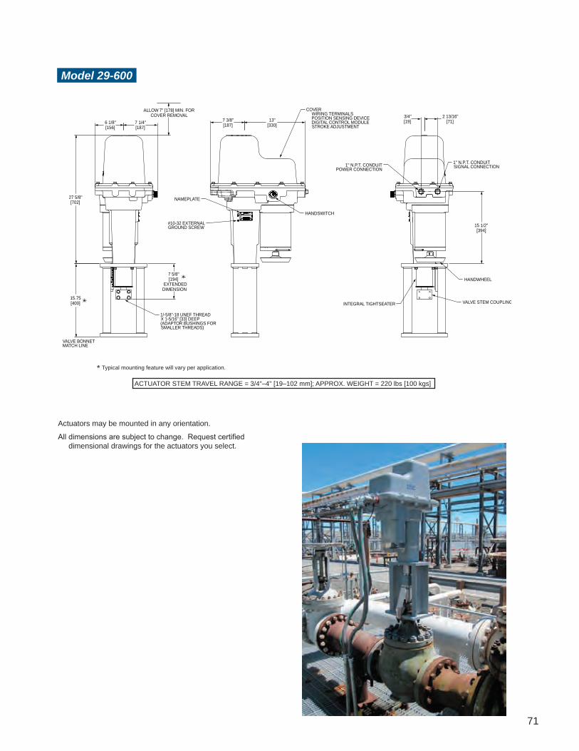
71
Typical mounting feature will vary per application.*
ACTUATOR STEM TRAVEL RANGE = 3/4"–4" [19–102 mm]; APPROX. WEIGHT = 220 lbs [100 kgs]
Actuators may be mounted in any orientation.
All dimensions are subject to change. Request certified dimensional drawings for the actuators you select.
Model 29-600
7 3/8"[187]
13"[330]
NAMEPLATE
#10-32 EXTERNALGROUND SCREW
COVERWIRING TERMINALSPOSITION SENSING DEVICEDIGITAL CONTROL MODULESTROKE ADJUSTMENT
HANDSWITCH
2 13/16"[71]
3/4"[19]
15 1/2"[394]
1" N.P.T. CONDUITPOWER CONNECTION
1" N.P.T. CONDUITSIGNAL CONNECTION
HANDWHEEL
INTEGRAL TIGHTSEATER VALVE STEM COUPLING
ALLOW 7" [178] MIN. FORCOVER REMOVAL
7 1/4"[187]
6 1/8"[156]
27 5/8"[702]
15.75[400]
7 5/8"[194]
EXTENDEDDIMENSION
VALVE BONNETMATCH LINE
1/-5/8"-18 UNEF THREADX 1-5/16" [33] DEEP(ADAPTOR BUSHINGS FORSMALLER THREADS)

72

73
Ideal ly sui ted for harsh industr ia l environments, the Group 42 handles long stroke applications requiring up to 1,000 lbs. of thrust (4450 N). The design employs a highly efficient ball screw coupled with a time-proven Beck motor and offers consistent, repeatable positioning as precise as 0.1% of span. Like all Beck actuators, the Group 42 incorporates a heavy-duty, weather-proof, cast aluminum body.
May be mounted in any orientation.
GROUP 42LINEAR ACTUATOR Long-stroke actuator providing up to 1,000 lbs. of thrust, ideally suited for burner air register type applications
Designed for long linear stroke applications, the Group 42 offers simplicity, flexibility and an easy-to-use package. Ideally suited for burner air register type applications, the Group 42 is flexible and can be used on many long linear stroke applications. The Group 42 is available with digital modulating control utilizing the Beck Digital Control Module (DCM) allowing all the advanced features, such as HART® capability, offered by microprocessor-based electronics. The Group 42 is also available with modulating analog control or direct AC control.
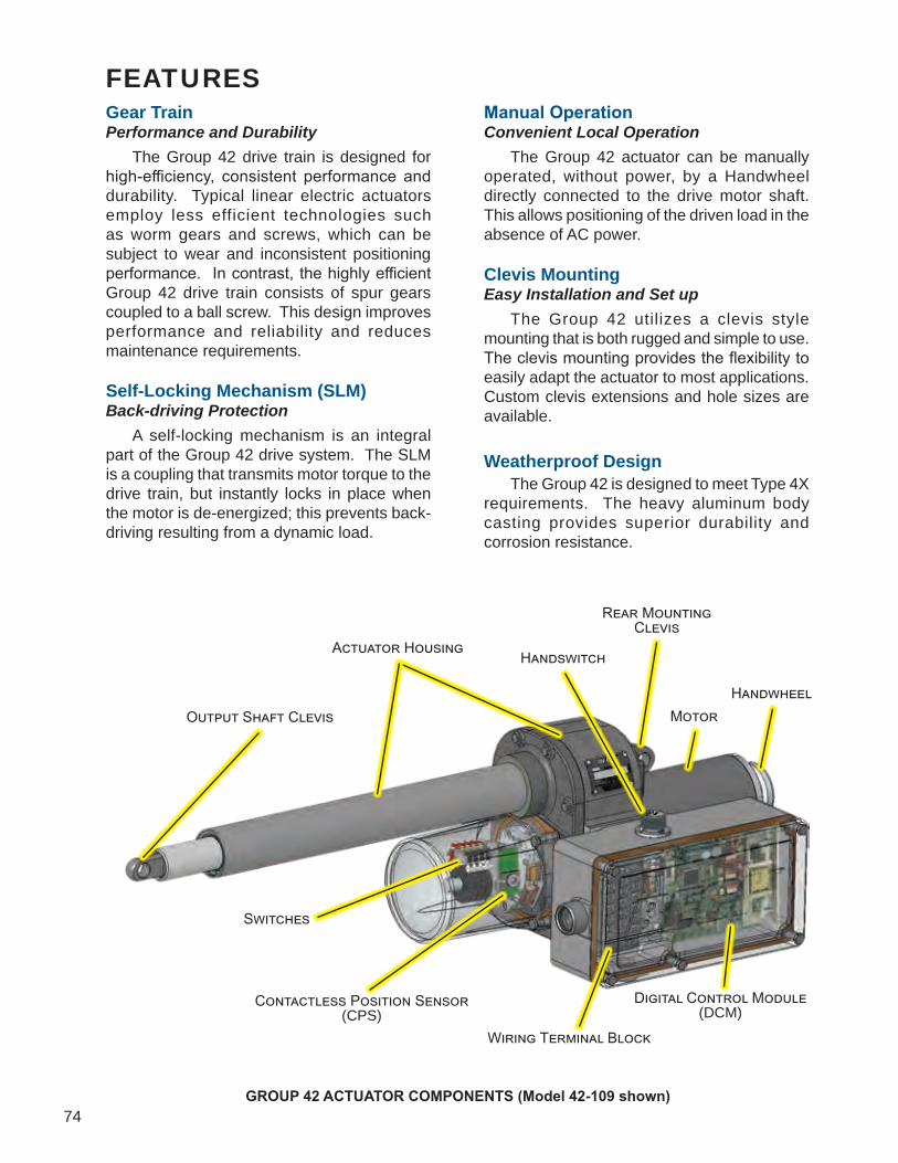
74
FEATURES
Wiring Terminal Block
Digital Control Module(DCM)
Switches
Contactless Position Sensor (CPS)
HandwheelMotor
Rear MountingClevis
HandswitchActuator Housing
Output Shaft Clevis
Gear TrainPerformance and Durability The Group 42 drive train is designed for high-efficiency, consistent performance and durability. Typical linear electric actuators employ less efficient technologies such as worm gears and screws, which can be subject to wear and inconsistent positioning performance. In contrast, the highly efficient Group 42 drive train consists of spur gears coupled to a ball screw. This design improves performance and reliability and reduces maintenance requirements.
Self-Locking Mechanism (SLM)Back-driving Protection A self-locking mechanism is an integral part of the Group 42 drive system. The SLM is a coupling that transmits motor torque to the drive train, but instantly locks in place when the motor is de-energized; this prevents back-driving resulting from a dynamic load.
Manual OperationConvenient Local Operation The Group 42 actuator can be manually operated, without power, by a Handwheel directly connected to the drive motor shaft. This allows positioning of the driven load in the absence of AC power.
Clevis MountingEasy Installation and Set up The Group 42 utilizes a clevis style mounting that is both rugged and simple to use. The clevis mounting provides the flexibility to easily adapt the actuator to most applications. Custom clevis extensions and hole sizes are available.
Weatherproof Design The Group 42 is designed to meet Type 4X requirements. The heavy aluminum body casting provides superior durability and corrosion resistance.
GROUP 42 ACTUATOR COMPONENTS (Model 42-109 shown)

75
MotorNo Burnout Beck actuators utilize a low current draw, continuous duty motor design. This motor ensures the actuator will not coast or overshoot and will not overheat—even under continuous modulation. The net result is consistent, repeatable positioning with no duty limitations.
Thrust Sensing Live output thrust sensing and protection is standard on Option 9 versions of the Group 42.
HandswitchComplete Local Control The Group 42 is equipped with an override manual Handswitch to aid in the setup and installation of the actuator independent of external control signals.
Auxiliary SwitchesEasily Adjustable Trip Points Up to two optional non-dedicated Form C switches are available. These switches are cam-operated and easily adjusted in the field. Wiring connections are provided in the actuator terminal compartment to allow easy access.
Control & Operating Features Group 42 actuators are available in several different control configurations including:Control Option 9: 4-20 mA modulating with a Digital Control Module (DCM), Contactless Position Sensor (CPS) and thrust sensing. This version includes both HART communications capabilities and local setup/diagnostic interface for simple calibration, setup and diagnostic capabilities.Control Option 7: 4-20 mA modulating with analog electronics and position feedback. This version has time-proven analog electronics on-board for simple, reliable no frills positioning and feedback of the actuator.Control Option 5: 120 Vac pulsed option. This version allows direct AC control of the actuator’s motor for either PAT type modulation or simple multi-position control.
42-107
42-109
Control Option 3: For simple open/close operation. Includes 2 limit switches which stop the actuator at each end of travel and may also be used for external signaling.
All Group 42 actuators are capable of providing consistently excellent modulating or multi-position control. They also provide easy access, installation and setup. Depending on the control option selected, the Group 42 can reliably position with steps as small as 0.1% of stroke. Actuators equipped with the DCM provide the best positioning performance and the most operating features. DCM equipped actuators include the following features: • Live thrust measurement and over-thrust
protection.• Two-way digital communications via HART
protocol.• Simple calibration and setup without electrical
or mechanical adjustments.• Actuator diagnostic capabilities.• Configurable action on loss of demand signal.• Stall protection with configurable stall time
setting.• Operating variables including thrust, position,
and actuator temperature are available via HART.
• The ability to restore all actuator calibration and setup parameters to factory “as-built” settings.

76
CONTROL OPTIONS & SAMPLE WIRING DIAGRAMS
Modulating Option 7Analog Position Control with Loop Powered Position Feedback Signal Customer must supply two wires to power the actuator: One 120 Vac line (terminal 1), and one neutral (terminal 2). Customer must supply two wires for the analog input control signal: Connect to terminal 11 (-) and to terminal 12 (+). The loop powered position feedback signal must be connected to a “2-wire” type analog input that provides a dc voltage over the signal wires (a dc voltage power supply must be wired in series with the signal wiring). If the dc supply is 24 to 35 volts, connect to terminal 14 (-) and to terminal 15 (+). If the dc power supply is 36 to 45 volts, reverse polarity and connect to terminal 14 (+) and to terminal 15 (-).
Analog Position Control with Actuator Powered Position Feedback Signal Customer must supply two wires to power the actuator: One 120 Vac line (terminal 1), and one neutral (terminal 2). Customer must supply two wires for analog control: Connect to terminal 11 (-) and to terminal 12 (+). Customer may supply two additional wires to monitor the analog position feedback signal: Connect to terminal 13 (-) and to terminal 14 (+). The actuator’s feedback circuit power supply is derived from the 120 Vac line, therefore the feedback signal must be wired to a "4-wire" type, non-powered analog input.
Diagrams are functional—customer wiring may vary. Certified wiring diagrams can be provided for the actuator you select.
Modulating Option 9Digital Position Control with Contactless Position Sensing The Beck DCM positions the actuator in proportion to an input current or voltage signal, and the CPS provides integral feedback for the DCM. A 4–20 mA position feedback signal is available for remote indication. The DCM may be used to provide pre-determined positioning of the actuator upon loss of input control signal.

77
Modulating Option 5Direct AC Control with Actuator Powered Position Feedback Signal Customer must supply three wires to directly control the actuator motor direction: One 120 Vac line to run Extend (terminal 10), one 120 Vac line to run Retract (terminal 9), and one neutral (terminal 2). Customer may supply two additional wires to monitor the analog position feedback signal: Connect to terminal 13 (-) and to terminal 14 (+). If position feedback monitoring is desired, a 120 Vac line must be connected to terminal 1. The actuator’s feedback circuit power supply is derived from this 120 Vac line, therefore the feedback signal must be wired to a “4-wire” type, non-powered analog input.
Direct AC Control with Loop Powered Position Feedback Signal Customer must supply three wires to directly control the actuator motor direction: One 120 Vac line to run Extend (terminal 10), one 120 Vac line to run Retract (terminal 9), and one neutral (terminal 2). Customer may supply two additional wires to monitor a loop powered position feedback signal. The loop powered position feedback signal must be connected to a “2-wire” type analog input that provides a dc voltage over the signal wires (a dc voltage power supply must be wired in series with the signal wiring). If the dc supply is 24 to 35 volts, connect to terminal 14 (-) and to terminal 15 (+). If the dc supply is 36 to 45 volts, reverse polarity and connect to terminal 14 (+) and to terminal 15 (-).
Option 3, Open/Close Direct AC Control Customer must supply three wires to directly control the actuator motor direction: One 120 Vac line to run Extend (terminal 10), one 120 Vac line to run Retract (terminal 9), and one neutral (terminal 2).

78
SPECIFICATIONSMODEL 42-109
Output Thrust and Timing 1,000 lbs. (4 450 N), 4.2 sec./in. (1.65 sec./cm)Stroke Range 5 to 18 inches (127 to 457 mm)Actuator Power 120 Vac, single-phase, 50 or 60 Hz, 1.3 A 240 Vac, single-phase, 50 or 60 Hz, .63 A—optional 208, 380, 415, 480, 575 Vac, 50 or 60 Hz—requires optional transformerWeight Approx. 75–89 lbs. (34 to 40 kg), depending on selected optionsOperating Conditions –40° to 85° C. (–40° to 185° F.); 0 to 99% relative humidityAvailable Communication Protocols HART® (standard). Options: Foundation Fieldbus, Profibus PA and Modbus RTU.
Demand Input Signal Range 4–20 mA, 1–5 VdcMinimum Step 0.1% of spanDemand Input Signal Characterization Linear: Actuator output shaft moves proportionally to the input signal Square: Actuator output shaft moves proportionally to the square of the input signal Custom: 20 segment configurable curve fitPosition Feedback Signal 4–20 mAIsolation Demand input and position Feedback signals are isolated from ground and the ac power line. Signal buffering provides 24 Vdc isolation between the Demand and Feedback signalsAction on Loss of Input Signal (Power On) Stays in place or runs to any preset position (configurable)Over-thrust Protection If actuator output thrust exceeds 150% (configurable to 70%) of the actuator rating, the motor will shut off (feature
can be enabled / disabled)Stall Protection If the motor tries to run in one direction for more than 300 seconds (configurable from 30 to 300 seconds), the motor will shut offOver-travel Protection Switches (Dedicated) Two Form C (Retract and Extend) provide over-travel protectionAuxiliary Switches (Non-dedicated) Two Form C, rated for 1 A, 250 VacHandswitch Permits local electrical operation, independent of Demand input signalHandwheel Provides manual operation without electrical powerApprovals CSA Labeled (US & Canada); CE Compliant NOTE: For standards not specifically listed, please call Beck for more information at 215-968-4600.Enclosure Precision-machined aluminum alloy, painted with corrosion-resistant polyurethane paint,to provide a rugged, dust-tight, weatherproof enclosure designed to meet Type 4, 4X; IP66.Mounting Orientation Can be mounted in any orientationHazardous Locations (Optional) Class II, Div. 1, Groups E, F & G; Class II, Div. 2, Groups F & G; Class III, Div. 1 & 2. NOTE: May not be available with all options & models. If these ratings do not meet your requirements, call Beck at 215-968-4600.

79
MODEL 42-107 & 42-105Output Thrust and Timing 1,000 lbs. (4 450 N), 4.2 sec./in. (1.65 sec./cm)Stroke Range 5 to 18 inches (127 to 457 mm)Actuator Power 120 Vac, single-phase, 50 or 60 Hz, 1.3 AWeight Approx. 64–69 lbs. (29 to 31 kg), depending on selected optionsOperating Conditions –40° to 85° C. (–40° to 185° F.); 0 to 99% relative humidityControl Options 1) Modulating analog control (Option 7); 2) Direct ac control (Option 5)Demand Input Signal (Option 7) 4–20 mA, 1–5 VdcDeadband 1.0% of spanMinimum Step .25% of spanPosition Feedback Signal 4–20 mA, 1–5 Vdc Feedback may be configured as a two wire transmitter or as a four wire active signal source. Two wire systems require a customer supplied external power supply. Four wire systems require 120 Vac supply to the drive.Isolation Demand input and position Feedback signals are isolated from ground and the ac power line. Signal buffering provides 24 Vdc isolation between the Demand and Feedback signals.Action on Loss of Power Stays in placeAction on Loss of Demand Input Signal (Option 7) Stays in place or moves to predetermined position with ac power suppliedStall Protection (Option 7) If the motor tries to run in one direction for more than approx. 2 minutes, it will shut offStall Relay Contacts (Option 7) Form A, 10 volt-amps at 120 Vac or dcAction on Stall (Option 7) Motor power is turned off when relay contacts open (after 136 seconds of stall) -- remote signal availableOver-travel Limit Switches (Dedicated) Two Form C (Retract and Extend), field adjustableAuxiliary Switches (Non-dedicated) Two Form C, rated for 1 A, 250 Vac, field adjustableHandswitch (Option 7) Permits local electrical operation, independent of Demand input signalHandwheel Provides manual operation without electrical powerApprovals CSA Labeled (US & Canada); CE Compliant NOTE: For standards not specifically listed, please call Beck for more information at 215-968-4600.Enclosure Precision-machined aluminum alloy, painted with corrosion-resistant polyurethane paint,to provide a rugged, dust-tight, weatherproof enclosure designed to meet Type 4, 4X; IP66.Mounting Orientation Can be mounted in any orientationHazardous Locations (Optional) Class II, Div. 1, Groups E, F & G; Class II, Div. 2, Groups F & G; Class III, Div. 1 & 2. NOTE: May not be available with all options & models. If these ratings do not meet your requirements, call Beck at 215-968-4600.

80
Drive Travel "L" dim. fullyretracted in. [mm]
"L" dim. fullyextended in. [mm]
Approx. Wt.(120 V) lb. [kg]
Approx. Wt.(240 V) lb. [kg]Max. in. [mm] Min. in. [mm]
8 [203] 5 [127] 18 19/32 [472] 26 19/32 [675] 75 [34] 84 [38]12 [305] 7 [178] 22 19/32 [574] 34 19/32 [879] 77 [35] 86 [39]18 [457] 11 [279] 28 19/32 [726] 46 19/32 [1 183] 80 [36] 89 [40]
Model 42-109OUTLINE DIMENSION DRAWINGS
Drives may be mounted in any orientation.All dimensions are subject to change. Request certified dimensional drawings for the drives you select.
FRONT VIEW REAR VIEW
SIDE VIEWNote:Front mounting clevis rotates 360°.Custom rear clevis extensions are available.
Front & Rear Clevis Hole Diameter Options
Ø.504±.003 [12.80±.076]Ø.754±.003 [19.15±.076]Ø.879±.003 [22.33±.076]
[87]
8" [203]Allow 3 3/4" for removal
of optional transformer cover

81
SIDE VIEW
FRONT VIEW REAR VIEW
Drive Travel "L" dim. fullyretracted in. [mm]
"L" dim. fullyextended in. [mm]
Approx. Wt.(120 V) lb. [kg]Max. in. [mm] Min. in. [mm]
8 [203] 5 [127] 18 19/32 [472] 26 19/32 [675] 64 [29]12 [305] 7 [178] 22 19/32 [574] 34 19/32 [879] 66 [30]18 [457] 11 [279] 28 19/32 [726] 46 19/32 [1 183] 69 [31]
Model 42-107/-105
Drives may be mounted in any orientation.All dimensions are subject to change. Request certified dimensional drawings for the drives you select.
DIA.
FOR REMOVAL
"L" DIMENSION
REAR CLEVISHOLE DIAMETER
FRONT CLEVISHOLE DIAMETER
FOR REMOVAL
3/4"
3/4" N.P.T. CONDUITPOWER CONNECTION
Note:Front mounting clevis rotates 360°.Custom rear clevis extensions are available.
3/4"
Front & Rear Clevis Hole Diameter Options
Ø.504±.003 [12.80±.076]Ø.754±.003 [19.15±.076]Ø.879±.003 [22.33±.076]

82
Burner Tilts The Beck 11-430 Electric Actuator provides up to 5,200 lb-ft [7 046 N•m] of torque for modulation of large dynamic loads such as multiple burner tilt arrays and large dampers. All of the flexibility, convenience, and reliability that distinguish Beck actuators are included in the 11-430 high torque actuator. To produce the 11-430, a Beck 11-400 actuator is mated with a large, durable gear reduction unit that increases the output torque by a factor of 3:1. The output shaft and crank arm have been designed to conservatively deliver this greater torque. The actuator is available with four different torque/timing options. See page 16 for details.
Variable Speed Couplings Beck Group 11 actuators are ideal for use with variable speed applications such as fluid drives and magnetic couplings. They provide exceptional stability and repeatability under live loads.
Hazardous Location Actuators Most Beck actuators are available rated for use in hazardous locations, allowing for utilization in refineries on heaters and gas valves, as well as other hazardous areas. Contact Beck's Sales Dept. or visit http://www.haroldbeck.com for more details.
SPECIALTY APPLICATIONSWhatever the application, there is a Beck actuator available to improve efficiency and reliability.

83
Pump Handle Valves B e c k G r o u p 11 actuators with fulcrum lever mountings provide accura te modu la t ing control of large linear globe valves. These virtually maintenance-f r e e a s s e m b l i e s reliably eliminate stick/sl ip and performance inconsistencies typical of pneumatic actuators. The fulcrum lever assembly accommoda tes h i gh thrusts while maintaining long-term reliability and precision. In addition, Group 11 actuators are available with hazardous location ratings.
Gate Dampers A mul t i - revo lu t ion Group 11 actuator is a v a i l a b l e f o r t h o s e applications in which a gravity-type gate must be raised or lowered in response to signal changes. Often used to regulate differential pressure by controlling balancing dampers on the hot exhaust side of furnaces, Beck actuators provide high accuracy and quick response even when continuously modulating. This results in greater fuel economy and longer refractory life.

84
Our experience shows proper installation to be among the most important factors in achieving long-term, maintenance-free service from your Beck actuator. To ensure a trouble-free installation, we will work directly with you through each step—from actuator selection to final installation. We can assist you with each of the following: • Actuator Selection. To specify the proper torque/thrust and timing. • Mounting Base Design. Design a long-lasting installation that protects the actuator and driven
equipment, and provides proper access clearances. Customized pedestals and adaptor plates are available.
• Linkage Design. Provide you with detailed linkage dimensions and linkage selection. • Retrofit Kits. Update your actuator to include the latest advances.
INSTALLATION ASSISTANCE
Old pneumatic actuator Beck replacement actuator
ACCESSORIES AND SERVICESBeck offers a wide range of accessories, services and unparalleled customer support to ensure complete satisfaction
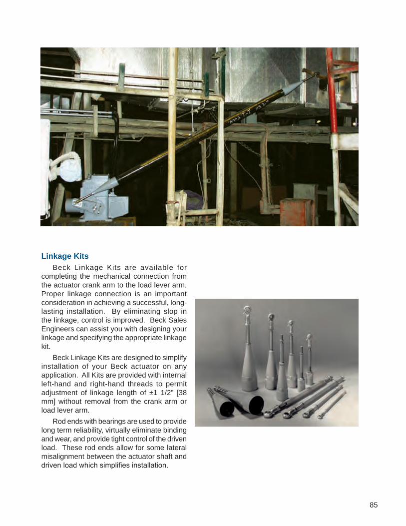
85
Linkage Kits Beck Linkage Kits are available for completing the mechanical connection from the actuator crank arm to the load lever arm. Proper linkage connection is an important consideration in achieving a successful, long-lasting installation. By eliminating slop in the linkage, control is improved. Beck Sales Engineers can assist you with designing your linkage and specifying the appropriate linkage kit. Beck Linkage Kits are designed to simplify installation of your Beck actuator on any application. All Kits are provided with internal left-hand and right-hand threads to permit adjustment of linkage length of ±1 1/2” [38 mm] without removal from the crank arm or load lever arm. Rod ends with bearings are used to provide long term reliability, virtually eliminate binding and wear, and provide tight control of the driven load. These rod ends allow for some lateral misalignment between the actuator shaft and driven load which simplifies installation.

86
Link-Assist™ The Link-Assist™ computer program optimizes the configuration for the load’s torque characteristics with the minimum actuator size to give you the best performance at the lowest possible cost. Link-Assist™ is available for the proper selection of the rotary actuator torque rating and linkage system for your valves and dampers. Beck Group 11 actuators may be specified to travel 100 degrees—regardless of full travel of the driven equipment—for enhanced control of damper or valve position. This feature also allows full flexibility in arranging the actuator’s torque to be distributed for the best mechanical advantage relative to the driven load. Full 100° actuator travel also provides the highest position resolution attainable using the full travel of the CPS feedback device. To take advantage of Beck’s Link-Assist™ program, provide the following information to your Beck Sales or Application Engineer: • Load torque characteristics, including maximum torque and load arm angular position • Load lever radius (and range, if adjustable) • Load lever shaft rotation range • Approximate load shaft to drive shaft center distance • Any space limitations, mechanical interferences or mounting conditions. You will receive the following data for your review: • Load shaft torque profile • Linkage length • Load and actuator crank arm radii • Load and actuator crank arm angular rotation range • Link force • Recommended Beck actuator and linkage kit • Data sheets to help collect and record the data are available by calling the factory or visiting our
website: http://www.haroldbeck.com/support/linkage_link-assist.htm
ScanforVideo

87
HAROLD BECK AND SONS, INC. June 29, 2007Newtown, PA 18940 Contact: BECK Sales Engineer 215-968-4600
YOUR Facility Information References: YOUR Desired Reference Info
LINK-ASSIST DATA SHEET
Note: Diagram is not drawn to scale - for reference only
BECK CONTROL DRIVE DATA LINKAGE DATA sehcni 00.42 :)H( .tesffO latnoziroH 904-11 :rebmuN ledoM
Rated Torque: 1800 lb-ft Vertical Offset....... (V): 36.00 inches sehcni 31.44 :)A( htgneL kniL gnitcennoC
BECK CRANK ARM DATA LOAD LEVER ARM DATARequired Rotation: 100 degrees Required Rotation: 90 degrees Start Position...: 1 degrees Start Position...: 10 degrees Radius (C): 8.99 inches Radius (L): 10.00 inches
CONTROL DRIVE LOAD LOAD LOAD LEVER/ CRANK ARM LEVER ARM LEVER CRANK ARM LINK ROTATION ROTATION TORQUE TORQUE RATIO FORCE Degrees degrees lb-ft lbs -------- -------- ------ ------------ ------ 0.0 0.0 2163 1.20 2792 10.0 8.5 2085 1.16 2572 20.0 17.2 2033 1.13 2449 30.0 26.2 1998 1.11 2403 40.0 35.2 1975 1.10 2429 50.0 44.4 1960 1.09 2531 60.0 53.6 1951 1.08 2726 70.0 62.8 1951 1.08 3053 80.0 72.0 1962 1.09 3592 90.0 81.1 1994 1.11 4533 100.0 90.0 2088 1.16 6420
2:39:00 PM
Note:SAMPLE LINK-ASSIST REPORT
SAMPLE LINK-ASSIST DATA SHEET

88
ROD END SUPPLIEDON BECK ACTUATOR
ROD END SUPPLIEDWITH LINKAGE KIT
LINKAGELENGTH
“A”
Hex Linkage Kit Specifications
Hex Linkage Assembly
“C”
“D”
“W”
Angle ofmisalignment
Linkage Rod End Data
Rod End Detail
Hex Linkage Kits When well-defined, short lengths are required, Hex Linkage Kits can be used. The table below provides information for specifying Hex Linkage Kits.
Hex Linkage Kits include: • Load lever rod end (the actuator rod end is
supplied with the Beck actuator) • Hex Linkage • Threaded Stud (2) • Jam Nuts (4)
The customer must supply the bolt for the load lever rod end. Use a bolt that results in the minimum clearance in the rod end. See dimension “D” in the bottommost table below.
Model Hex Size
Linkage LengthRange "A", in [mm] Linkage Kit
Part No.
Approx.Weight,lbs [kgs]Min. Max.
31-___ 7/16
9 [229] 12 [305] 14-7990-22 .5 [.23]12 [305] 15 [381] 14-7990-24 .5 [.23]15 [381] 18 [457] 14-7990-26 .75 [.34]18 [457] 21 [533] 14-7990-10 1 [.45]
11-15_ 5/8
9 [229] 11.5 [292] 14-8300-22 1 [.45]10.5 [267] 14.5 [368] 14-8300-32 1 [.45]14.5 [368 18.5 [470] 14-8300-04 1 [.45]18 [457] 22 [559] 14-8300-06 2 [.91]22 [559] 26 [660] 14-8300-16 2 [.91]
11-20_ 5/8
9 [229] 11.5 [292] 14-8300-22 1 [.45]10.5 [267] 14.5 [368] 14-8300-32 1 [.45]14.5 [368] 18.5 [470] 14-8300-04 1 [.45]18 [457] 22 [559] 14-8300-06 2 [.91]22 [559] 26 [660] 14-8300-16 2 [.91]
11-30_ 1
13.5 [343] 18 [457] 14-8860-24 2 [.91]17.5 [445] 22 [559] 14-8860-08 3 [1.36]22 [559] 26.5 [673] 14-8860-02 4 [1.81]
26.5 [673] 31 [787] 14-8860-04 5 [2.27]
11-40_ 1
13.5 [343] 17.5 [445] 15-0110-26 3 [1.36]18 [457] 22 [559] 15-0110-20 4 [1.81]22 [559] 26 [660] 15-0110-03 5 [2.27]26 [660] 30 [762] 15-0110-22 6 [2.72]29 [737] 33 [838] 15-0110-02 6 [2.72]
Model 31-___ 11-15_ 11-20_ 11-30_ 11-40_ 11-43_ 22-___Thread Size 5/16-24 1/2-20 1/2-20 5/8-18 3/4-16 1 1/2-12 1 1/2-12
Dim. "C", in. [mm] .437 [11.1] .625 [15.875] .625 [15.875] .750 [19.05] .875 [22.225] 1.312 [33.324] 1.312 [33.324]Dim. "D", in. [mm] .3125 [7.938] .500 [12.7] .500 [12.7] .625 [15.875] .750 [19.05] 1.500 [38.1] 1.500 [38.1]Dim. "W", in. [mm] .437 [11.1] .750 [19.05] .750 [19.05] .875 [22.225] 1.000 [25.4] 2.000 [50.8] 2.000 [50.8]
Angle θ 14º 12º 12º 16º 14º 6.5º 6.5º
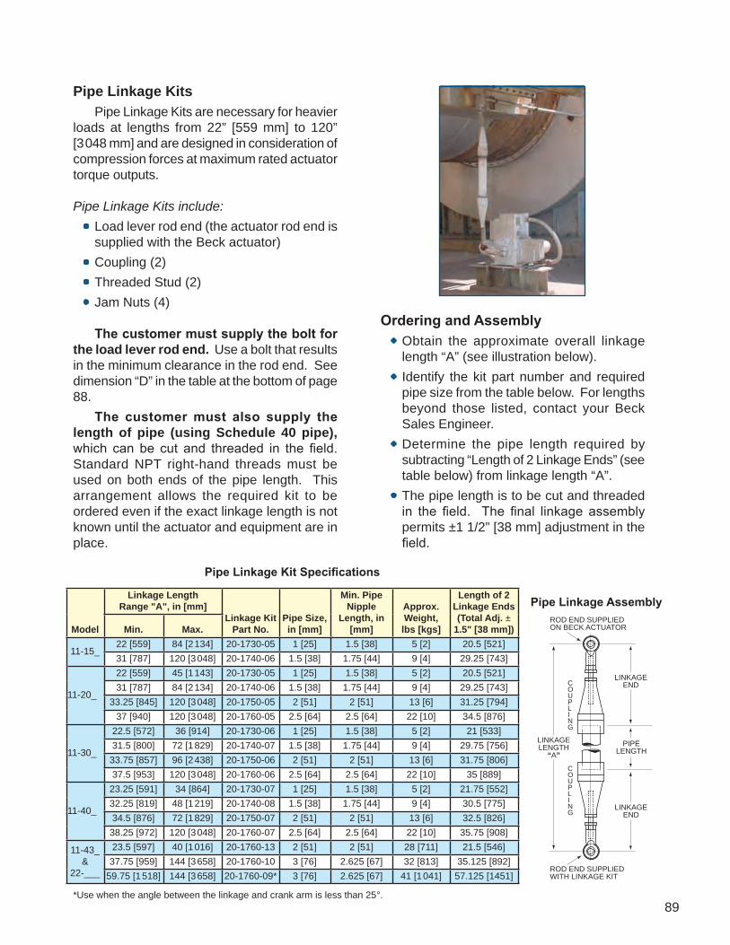
89
Pipe Linkage Kit Specifications
ROD END SUPPLIEDON BECK ACTUATOR
ROD END SUPPLIEDWITH LINKAGE KIT
COUPLING
COUPLING
PIPELENGTH
LINKAGELENGTH
“A”
LINKAGEEND
LINKAGEEND
Pipe Linkage Assembly
Pipe Linkage Kits Pipe Linkage Kits are necessary for heavier loads at lengths from 22” [559 mm] to 120” [3 048 mm] and are designed in consideration of compression forces at maximum rated actuator torque outputs.
Pipe Linkage Kits include: • Load lever rod end (the actuator rod end is
supplied with the Beck actuator) • Coupling (2) • Threaded Stud (2) • Jam Nuts (4)
The customer must supply the bolt for the load lever rod end. Use a bolt that results in the minimum clearance in the rod end. See dimension “D” in the table at the bottom of page 88. The customer must also supply the length of pipe (using Schedule 40 pipe), which can be cut and threaded in the field. Standard NPT right-hand threads must be used on both ends of the pipe length. This arrangement allows the required kit to be ordered even if the exact linkage length is not known until the actuator and equipment are in place.
Ordering and Assembly • Obtain the approximate overall linkage
length “A” (see illustration below). • Identify the kit part number and required
pipe size from the table below. For lengths beyond those listed, contact your Beck Sales Engineer.
• Determine the pipe length required by subtracting “Length of 2 Linkage Ends” (see table below) from linkage length “A”.
• The pipe length is to be cut and threaded in the field. The final linkage assembly permits ±1 1/2” [38 mm] adjustment in the field.
*Use when the angle between the linkage and crank arm is less than 25°.
Model
Linkage LengthRange "A", in [mm]
Linkage KitPart No.
Pipe Size, in [mm]
Min. Pipe Nipple
Length, in [mm]
Approx.Weight,lbs [kgs]
Length of 2 Linkage Ends (Total Adj. ±
1.5" [38 mm])Min. Max.
11-15_22 [559] 84 [2 134] 20-1730-05 1 [25] 1.5 [38] 5 [2] 20.5 [521]31 [787] 120 [3 048] 20-1740-06 1.5 [38] 1.75 [44] 9 [4] 29.25 [743]
11-20_
22 [559] 45 [1 143] 20-1730-05 1 [25] 1.5 [38] 5 [2] 20.5 [521]31 [787] 84 [2 134] 20-1740-06 1.5 [38] 1.75 [44] 9 [4] 29.25 [743]
33.25 [845] 120 [3 048] 20-1750-05 2 [51] 2 [51] 13 [6] 31.25 [794]37 [940] 120 [3 048] 20-1760-05 2.5 [64] 2.5 [64] 22 [10] 34.5 [876]
11-30_
22.5 [572] 36 [914] 20-1730-06 1 [25] 1.5 [38] 5 [2] 21 [533]31.5 [800] 72 [1 829] 20-1740-07 1.5 [38] 1.75 [44] 9 [4] 29.75 [756]33.75 [857] 96 [2 438] 20-1750-06 2 [51] 2 [51] 13 [6] 31.75 [806]37.5 [953] 120 [3 048] 20-1760-06 2.5 [64] 2.5 [64] 22 [10] 35 [889]
11-40_
23.25 [591] 34 [864] 20-1730-07 1 [25] 1.5 [38] 5 [2] 21.75 [552]32.25 [819] 48 [1 219] 20-1740-08 1.5 [38] 1.75 [44] 9 [4] 30.5 [775]34.5 [876] 72 [1 829] 20-1750-07 2 [51] 2 [51] 13 [6] 32.5 [826]
38.25 [972] 120 [3 048] 20-1760-07 2.5 [64] 2.5 [64] 22 [10] 35.75 [908]
11-43_&
22-___
23.5 [597] 40 [1 016] 20-1760-13 2 [51] 2 [51] 28 [711] 21.5 [546]37.75 [959] 144 [3 658] 20-1760-10 3 [76] 2.625 [67] 32 [813] 35.125 [892]
59.75 [1 518] 144 [3 658] 20-1760-09* 3 [76] 2.625 [67] 41 [1 041] 57.125 [1451]

90
Hazardous Location Ratings Most Beck actuators are available CSA listed and CE compliant for use in hazardous locations.
Specialized Applications Packages Most Beck actuators are available with specialized setups for highly corrosive environments or high vibration applications.
Backup Power Supply The Beck Backup Power Unit (BPU)provides short-duration, backup power for Beck actuators. It is designed to provide power for fail-to-position actuator response or to maintain normal actuator operation for a short period. The BPU is available for ordinary and hazardous locations. A unit with an additional bank of ultra-capacitors is also available.
Fully charged, the unit will provide backup power for a time dependent upon the power draw required by the actuator motor. Approximate times for the duration of output power (based on wattage) are:
WattsSeconds
Single Bank
DoubleBank
34(1 N•m, 72 RPM motor) 109 218
62 58 11687
(3 N•m, 72 RPM motor) 44 88
101 37 74137 26 52
OPTIONS After the unit has been fully discharged, it will take approximately 30 minutes to be completely recharged (~60 minutes for the optional, dual capacitor bank unit).
Remotely Mounted Digital Control Module (DCM) Most Beck actuators equipped with digital control are available with the option to remotely mount the DCM. The separate enclosure which houses the DCM may be positioned at any convenient distance from the actuator and is available with or without a Handswitch. This option is ideal for actuators located in extreme environments.
DCM with Feedback Display Actuators equipped with this feature have a display window built into the DCM compartment cover. This window reveals an LED display showing the position of the actuator based on Feedback loop current (displayed as a percentage of travel within a tenth of a degree). Also visible through the window are LEDs that light green and red (respectively) at adjustable positions of travel (as a percentage of total travel).

91
Remote Indication Station with or without Control An indication station with a stainless steel enclosure is available which could be mounted at the actuator site or at a remote location. An indication station with manual or auto/manual control is also available.
Handswitch Options Beck Handswitches are available with an auxiliary contact for remote indication. Locking Handswitches are also available.
DPDT Override Available to provide a control system emergency override relay.
Crank Arm Options For applications where the standard crank arm will not suffice, extra long or shorter crank arms may be equipped as an option on some Beck actuator models.
SST Hardware Stainless steel hardware is available for applications in high humidity or particularly wet environments.
Epoxy Paint For environments where the Beck actuator will come into regular contact with grease, oil, etc., a tough, long-lasting epoxy paint is available for added protection.
Torque / Thrust Sensing Most option 9 Beck actuators are capable of measuring actuator torque or thrust output. Depending on the model, this may be an extra cost option. This capability provides several features, including:• A live display of the torque / thrust output.• The ability to store peak torque / thrust
values.• Ten-segment peak torque / thrust profile for
actuator output trending and final control element diagnostics.
• A high torque / thrust alarm that alerts the user when the torque / thrust output exceeds a set value (normally set at 105% of the actuator rating).
• Overtorque / overthrust protection that will shut off power to the motor if the torque / thrust exceeds a specified percentage of the actuator rating (e.g., 150% for Group 11 drives). This value is configurable.
480 Volt Power Option (Group 11) Typical electric actuators are less efficient than Beck actuators and require 480 Volt, 3-phase power. Due to this requirement, retrofitting a Beck actuator often necessitates new 120 Volt, 1-phase power wires be run to the site. To eliminate this expense and simplify the retrofit, Beck offers an optional 480 Volt power feature for all Group 11 models. This option includes a transformer, power terminations and fusing integral to the actuator body. Beck Group 11 actuators are also available with 208, 240, 380, 415 & 575 V options.

92
Mounting Pedestals Standard and custom retrofit pedestals are available, including designs for a number of common pneumatic actuators such as the Bailey AC and UP series and Hagan cylinders.
Adaptor Plates Transition from first generation Beck mechanisms and old L & N and Honeywell electric actuators are made easily with pre-drilled, fabricated plates.
Thermal Barriers Micarta insulation kits are available for all Beck actuators to mitigate heat conduction from the mounting plate.
ACCESSORIES
Application Reviews By sharing your needs with a Beck Factory Sales Engineer, you can take advantage of the best application advice for the type of control you need. This review will yield a better understanding of the versatility of Beck actuators for your installations, as well as complete details on options and accessories to make the process as effective as possible.
Specification Writing Beck provides specification writ ing assistance in order to help you specify and order the right actuators for your applications. Beck Factory Sales Engineers will work with you to make it easier for you to obtain the proper equipment and give you confidence that no details are overlooked.
Product Demonstrations Beck Factory Sales Engineers can demonstrate virtually any actuator feature by bringing an actuator to your location. To arrange to see a Beck actuator in your plant or office, contact the Beck’s Sales Department.
FACTORY SUPPORT & SERVICES

93
Site Surveys Beck Factory Sales Engineers are available to discuss your process control requirements. A visit to your location is often the best way to gain a thorough understanding of your needs in order to meet them most accurately and completely. Beck’s analysis at the job site can help ensure that specifications are accurate—particulary for complex applications.
Valve Specification Assistance If you are planning to order valves, Beck Application Engineers will assist you in specifying the right valve for the application. Beck will factory-mount our actuator to the valve and ship it to you fully calibrated and ready for simple drop-in installation.
Spares Planning Service Beck Spares Planning Service is offered to assist you in stocking key spare parts. We will recommend the minimum number of parts that you should have in stock for the Beck actuators you have in service—providing for fast and efficient replacement on critical units.
Troubleshooting Assistance Because Beck actuators are constructed with no-burnout motors, sealed electronics and powerful gear trains, they require no periodic maintenance. In the event that a problem does occur, you can refer to detailed instruction manuals, complete with troubleshooting guide, to determine the corrective procedure. This, combined with free on-call phone assistance, will resolve almost any problem and will get you back online quickly.
Factory Repair Factory repair of drives or subassemblies is available for both normal and emergency service. To assure prompt processing, contact the factory to receive a Returned Material Authorization (RMA) number. If a repair estimation is desired, please send the name and phone number of your contact for service authorization. It is helpful to include a description of the work desired with the shipment or, in the event of a problem, the malfunction being experienced.
Training Services Beck’s technical personnel can provide training services at your plant location. Training topics will include mechanical and electrical installation, diagnostics and troubleshooting, maintenance, and repair.
94

95

HARO
LDBECK.CO
MHAROLD BECK & SONS, INC11 TERRY DRIVE • NEWTOWN, PA 18940 • USAPHONE: 215-968-4600 • FAX: [email protected] • HaroldBeck.com
INDUSTRIES SERVED INCLUDE:ELECTRIC POWER • STEEL & ALUMINUM • WATER & WASTEWATER • PULP & PAPER
CEMENT & LIME • CHEMICAL & PETROCHEMICAL • GLASS • OIL & GAS2/19