elastic wave propagation in media with parallel …santos/research/fracture_references/... ·...
TRANSCRIPT

Geophysical Prospecting 36,571-590,1988
ELASTIC WAVE PROPAGATION IN MEDIA WITH PARALLEL FRACTURES AND ALIGNED CRACKS'
M . SCHOENBERG2 and J . D O U M A 3
ABSTRACT SCHOENBERG, M. and DOUMA, J. 1988. Elastic wave propagation in media with parallel frac- tures and aligned cracks. Geophysical Prospecting 36,571-590.
A model of parallel slip interfaces simulates the behaviour of a fracture system composed of large, closely spaced, aligned joints. The model admits any fracture system anisotropy : triclinic (the most general), monoclinic, orthorhombic or transversely isotropic, and this is specified by the form of the 3 x 3 fracture system compliance matrix. The fracture system may be embedded in an anisotropic elastic background with no restrictions on the type of anisotropy. To compute the long wavelength equivalent moduli of the fractured medium requires at most the inversion of two 3 x 3 matrices. When the fractures are assumed on average to have rotational symmetry (transversely isotropic fracture system behaviour) and the background is assumed isotropic, the resulting equivalent medium is transversely iso- tropic and the effect of the additional compliance of the fracture system may be specified by two parameters (in addition to the two isotropic parameters of the isotropic background). Dilute systems of flat aligned microcracks in an isotropic background yield an equivalent medium of the same form as that of the isotropic medium with large joints, i.e. there are two additional parameters due to the presence of the microcracks which play roles in the stress- strain relations of the equivalent medium identical to those played by the parameters due to the presence of large joints. Thus, knowledge of the total of four parameters describing the anisotropy of such a fractured medium tells nothing of the size or concentration of the aligned fractures but does contain information as to the overall excess compliance due to the fracture system and its orientation. As the aligned microcracks, which were assumed to be ellipsoidal, with very small aspect ratio are allowed to become non-flat, i.e. have a growing aspect ratio, the moduli of the equivalent medium begin to diverge from the standard form of the moduli for flat cracks. The divergence is faster for higher crack densities but only becomes significant for microcracks of aspect ratios approaching 0.3.
Presented in part at the 49th EAEG meeting, Belgrade, June 1987; revision accepted Feb- ruary 1988. Schlumberger-Doll Research, Ridgefield, CT 06877-4108, USA. Institute for Earth Sciences, Department of Geophysics, PB 80021, 3508 TA Utrecht, The Netherlands.
571
512 M . SCHOENBERG AND J . DOUMA
INTRODUCTION It is now clear that there are many regions of the subsurface (some say everywhere) showing azimuthal velocity anisotropy and this has been attributed to the presence of aligned vertical microcracks that arise because of tectonic stresses (see e.g. Crampin 1985; Crampin and Atkinson 1985; Willis, Rethford and Bielanski 1986; Crampin and Bush 1986). That this Crampin model is the actual mechanism causing the azimuthal velocity anisotropy is difficult to say as drilling and coring in such a region distort the stress field locally and perhaps distort and close the cracks that existed in the undeformed rock. A set of robust parameters is needed to give (1) the orientation of the cracks and/or fractures in the subsurface, and (2) a measure of crack density times strength which could be called excess compliance due to the presence of cracks. Such a parameter set could be a valuable indicator of overall stress orientation, and the orientation and strength of the anisotropic part of the permeability tensor. Crack orientation, when cracks are vertical, can be simply determined by the splitting of vertically propagating shear waves. This occurs because of the azimuthal anisotropy induced by microcracks and fractures. The polarization of the faster propagating shear wave according to current theory is parallel to the fractures; the polarization of the slower propagating shear wave is perpendicular to the fractures.
We compare theories that predict elastic anisotropy due to the presence of filled or empty ellipsoidal inclusions with one another and with a theory that predicts elastic anisotropy due to long (compared to wavelength) parallel joints or fractures. For inclusions with small aspect ratios (almost flat cracks), all the models agree with one another and in fact they are indistinguishable from the fracture model. The fracture model is exactly derivable as the limiting case of wave propagation through a region composed of alternating elastic layers. The results for anisotropic layers are reviewed in Section I and the derivation of the fracture model in its most general form and for special cases is presented in detail in Section 11. In Section 111, the simplest anisotropy attributable to ' transversely isotropic ' fractures in an isotropic background is compared in detail with the anisotropy due to systems of aligned flat microcracks. In both the anisotropy is characterized by two, positive, dimensionless parameters that play the same roles in the stress-strain relations. The first depends on the tangential compliance of the joints or cracks and the second depends on the normal compliance. From a phenomenological point of view the behaviour of such systems of aligned flat cracks or parallel joints can be reduced to two numbers which, with the isotropic background moduli, determine the five elastic moduli of a transversely isotropic elastic medium. From the elastic moduli themselves nothing more specific concerning crack density, individual crack compliance or crack size can be found.
However, in Section IV it will be shown that for the ellipsoidal inclusions, as the aspect ratio becomes large (up to l.O), the moduli derivable from the theory of ellipsoidal inclusions (Nishizawa 1982) deviate from those obtainable from the flat crack or joint theories. This occurs at aspect ratios of about 0.3 for gas- or liquid- filled inclusions at the highest values of crack density of such inclusions for which the theory is thought to be valid.

ELASTIC WAVE P R O P A G A T I O N 573
I . ELASTIC M O D U L I O F STRATIFIED M E D I A Consider a stratified medium made up of perfectly bonded homogeneous, but not necessarily isotropic, layers. Let the x3-axis be perpendicular to the layering and assume that there are n different constituent layers, arranged so that in each suff- ciently large interval one finds the same proportion of each medium. The simplest arrangement that satisfies this requirement is a periodic sequence of layers. Each anisotropic constituent has a relative thickness hi i = 1, . . . , n so that hl + . . . + h, = 1, a density p i , and an elastic modulus tensor cpqrsi, relating stress opqi with
strain E , , ~ . In condensed notation, for which subscripts 11 + 1, 22 -+ 2, 33 -+ 3, 23 + 4, 31 + 5 and 12 -+ 6, the stress-strain relation may be written
. - cJ1
cJ2
cJ3
cJ4
cJ5
06-
where
and
The elastic moduli for the homogeneous, anisotropic medium equivalent, in the long wavelength (or quasistatic) limit, to a layered medium composed of anisotropic con- stituent layers, can be expressed in terms of thickness-weighted averages of functions of the moduli of the constituents. The long wavelength assumption on stress is that all stress components acting on surfaces parallel to the layering are the same in all layers, i.e. 033i = c~~~ = c3 , ~ ~ 2 3 ~ = 04i = o4 and 013i E oSi = 0 5 . The long wave- length kinematic assumption is that over many layers, the layers move together (so that derivatives of in-plane displacements with respect to in-plane coordinates, x1 and x2, are the same) implying that all strain components lying in the plane of the layering are the same in all layers, i.e. c l l i = = cZi = e2 and 2~~~~ = &gi = & 6 . The other stress and strain components, cll i = oli , oZzi o Z i , o lZi = usi,
esi, may vary from layer to layer. In each layer, such a component may be taken as its average value across the thickness of that layer.
A concise way to pose the problem of finding the effective moduli, even when the constituent layers are anisotropic, is through a matrix formulation which dis- tinguishes components that are constant over many layers from the other com- ponents which can vary from layer to layer. Following the procedure first outlined
= el,
c g i , 2~~~~ = zqi and 2~~~~

514 M . SCHOENBERG AND J. DOUMA
by Helbig and Schoenberg (1987) for general anisotropic layers, define the following vectors
Sli = bZi , Ezi = , layer dependent [::I [::I and
S, = [I:], E, = [!:I, layer independent
which allow the stress-strain relations in any layer to be rewritten as
Sii = MiE, + PiE2i,
S2 = PTE, + Ni E,, .
with superscript T denoting the matrix transpose. Mi and Ni are symmetrical matrices. Then premultiplying (3b) by N; gives
Nlr1S2 = Nr'PTE, + ( 5 )
Sli = MiE, + Pi(NlF1S2 - Nr1PTE1). (6)
and solving this for E,i and substituting into (3a) yields
n
Now let the thickness-weighted average over all the constituent layers, 1 hi(.i), be denoted as ( . ). Then taking first, the thickness-weighted average of (6), and second, the thickness-weighted average of (5 ) and premultiplying this second result by (N-')-' gives
i = l
(S,) = [(M) - (PN-'PT)]E, + (PN-')S,,
S, = (N-')-'(N-'PT)E1 + (NP1)-'(E2). (74
(7b) Finally substituting the expression for S, from (7b) into (7a) allows us to write the elastic moduli for the media equivalent to the stratified medium in the long wave- length limit, in matrix form as
(S,) = Me E, + Pe(E2) 9
S2 = P,TE, + Ne(E2) 9
(84
(8b) with
N, = (N-')-', Pe = (PN-')N,,
Me = (M) - (PN-'PT) + (PN-')N,(N-'PT). (9)

ELASTIC WAVE PROPAGATION 575
If the ith constituent is transversely isotropic with the x,-axis, the axis of sym- metry, then, from the expressions for Mi , Ni and Pi in (4), we have
cl l ; -2c66; :], C l l i
0 c66;
[rgl : 1, Pi= "13' ~ 1 3 ~ 0 "1 0 I Ni = 0 c~~~ 0 c44; 0 0 0
Note that when the ith constituent layer is isotropic, c44i = c66i = pi, c l l i = c,,~ = ,Ii + 2pi and cl3; = ,Ii where ,Ii and pi are Lamb parameters. If all the constituent layers are transversely isotropic, the equivalent homogeneous medium is trans- versely isotropic and from (9) the moduli are given by
0 0
cl, cl, -2c6, 0 1 cl , cll -2(c66) 1, 0 = c11 - XC,,) C l 1
1 0 0 c66 1 1 O 0 (C6.5)
c l l - 2 c 6 6 cll
C i i = ( C i i ) - <c:3/c33) + (c13/C33>~/(1/~33>,
identical to the results of Backus (1962). Note that the combination rules (9) are commutative in layer order. If, instead of
considering the relative thickness hi of each constituent, the combination operation is thought of as the folding together of a total thickness Hi of each constituent, albeit divided into fine layers, then the combination rules (9) are also associative (Schoenberg and Muir 1988). Thus, if there are three constituents of total thickness H , , H , and H , , the properties of the combined medium of thickness H , + H , + H , can be determined by first finding the properties of the medium equivalent to con- stituent 3 mixed with constituent 1, and then stirring in amount H , of constituent 2. The resulting equivalent medium is independent of the order of combination.
11. GENERAL MODEL F O R LONG T H I N PARALLEL FRACTURES The behaviour of long parallel fractures or joints in an otherwise homogeneous anisotropic background medium may be modelled as a set of thin constituent layers, not necessarily isotropic, embedded in the background. The above derived formal-

576 M . S C H O E N B E R G AND J . ' D O U M A
ism is used and the fractures are modelled by taking the limit as the thickness and the elastic moduli of the embedded thin layers go to zero together. The formalism enables us to identify the effect of even the most anisotropic fractures on the most anisotropic background, and to see the variation in anisotropic behaviour permitted by sets of large parallel fractures. The fracture behaviour is at its simplest if the material inside the fracture is assumed to be transversely isotropic; the assumption of full isotropy implies no further simplification. This type of fracture behaviour is discussed and compared with the behaviour of dilute concentrations of aligned inclusions that may be assumed to model a medium with internal cracks where the cracks have a preferred orientation.
For now, the material inside the fracture is allowed to have arbitrary anisotropy. The fracture-filling material is assumed to be soft by letting the moduli of the frac- ture layer, Cjkl be much smaller than a typical non-zero background modulus, say c~~~ (the effect of a hard fracture-filling material would tend to vanish as the fracture widths approached zero). In particular, the moduli are assumed to be of the order of the volume ratio of the fractures h,, i.e. C j k J / C 3 3 * = O(h,). Here h, may be thought of as the total fracture thickness in an interval of width H divided by H . The interval width H must satisfy two criteria. It must be sufficiently large so that the fractured medium has the same total thickness of fractures h, H in any interval of thickness H . Yet H must be much smaller than the smallest wavelength of interest for the frac- tured medium to be replaced by a long wavelength equivalent homogeneous medium. The assumption on the CjkJ means that, in the limit, as.h, + 0 the c j k J may be replaced by h , z j k and, from (9) as h , + 0,
Ne = (N-')-' = [(l - hf)Nb' + h, Ny']-' +(Nbl + R-')-' = Nb(I + N-'Nb)-' (12)
pe + (pb Nb 'lNe > Me Mb - pb Nb lpb' + (Pb Nb l)Ne(Nb lpb'), ( p ) --* P b 2
where I is the 3 x 3 identity matrix. The fracture parameters enter only through R, a symmetrical 3 x 3 submatrix of the full 6 x 6 modulus matrix, so that in general there are at most six fracture parameters, the six independent components of m. To see why this must be so, consider (3b) for the fracture medium, which gives the components of the stress traction across the fracture. They are
S, = hf( pT[ + .[:::I). Since the fractures are soft, strain components in the fracture layers are large and can be approximated by - Au3/h, H , - Au,/h, H and - AuJh, H where h, H is the total fracture width in an interval of width H and Aui are the com- ponents of the total slip displacement across all the fractures in that interval of width H . The other strain components in the fracture layers are constrained by the long wavelength assumption to be the same as the corresponding components in the

ELASTIC W A V E PROPAGATION 511
background medium and thus are not large. Then, in the limit as h, + 0,
AU3/hf H = h, P; cZ + R Auz/h,H +N Auz/H . (14)
" = [ 3f] = [ (- [.:] [ Au,/h, A) [:I:::] In subsequent development the 'fracture system compliance matrix' Z = m-' will be used instead of m as small slip or vanishing of some components of the fracture system slip-strain will cause m to be very large or undefined, while causing Z merely to have some small or zero components. Thus (14) becomes
Define the vector on the left, the slip-displacement vector of the fractures in width H divided by H, as the 'fracture system slip-strain.' Then Z gives the fracture system slip-strain as a linear function of the traction on any x3 =constant surface (Schoenberg, 1980). Note that it is perfectly acceptable that some of the components of N, + 0 as h, + 0 and for others to remain finite. This is accounted for in the evaluation of the term h,Nj', which approaches Z, occuring in the first equation of (12) for N,.
Rewriting the first equation of (12) as
N, = Nb(1 ZNb)- ', (16)
enables us to write the matrices of the changes from the background moduli due to the fractures, from (12), as
AN = Nb[(I + ZNb)-l - I],
AP = (Pb Nb ')AN, AM = (Pb Nb ')AN(N, 'Pr). (17)
When Z is so small that all terms of ZNb 6 1, we see that N, w Nb - NbZNb and
As an aside, note that had we begun with a compliance formulation, writing strain as an elastic compliance matrix times stress, i.e. c j = s j k (Tk , the strain-stress relations could be written analogously with (3) as
AN % -NbZNb.
E, = AiSli + CiSz, Ezi = CTSli + BiSz ,
then the matrices of the changes from the background compliances due to the pre- sence of the fractures are AA = 0, AC = 0 and AB = Z.
From the associativity of the process of combining layers, even when there are many types of parallel fractures in the medium, it is the overall compliance of all of them that can be combined to form an 'effective fracture behaviour' which is the average of the different types of fractures weighted by the respective fracture density.

578 M . SCHOENBERG A N D J. D O U M A
t
t 1
+ x
b)
FIG. 1. A schematic of a fracture (a) with monoclinic behaviour and (b) with orthorhombic behaviour. In both cases the ridges cause the tangential traction and tangential slip not to be parallel unless they are either parallel or perpendicular to the ridge axis. In (a), additionally, closure or opening of the fracture will cause tangential slip in the x,-direction and vice versa but is uncoupled from tangential motion in the x,-direction.
In general, from (15), all three components of the fracture system slip-strain are coupled to all three components of the traction across the fractures. This is the case of triclinic fracture system anisotropy. For this most general behaviour, six param- eters are needed to fully describe fracture behaviour within an otherwise homoge- neous medium, the six independent components of the fracture compliance matrix Z. However, there are three symmetry classes that apply to fracture systems that reduce the number of independent fracture system parameters.
The monoclinic fracture system. Let the fracture system be invariant under reflec- tion about a plane containing the x3-axis, say the x I - x ~ plane, implying that Z has the form
This shows that fracture slip in the x,-direction is uncoupled from normal slip and tangential slip in the x,-direction. The x,-tangential slip is not uncoupled from normal slip. Tangential fracture displacement and the tangential component of the stress traction are not colinear. Such fracture system behaviour need not be due to the anisotropy of the infilling material, but could be due to slight micro-corrugation of the fracture surfaces, which then must have its peaks and troughs slightly offset, top to bottom, to couple normal and tangential components. This is shown by the schematic diagram in Fig. la.
ELASTIC WAVE PROPAGATION 519
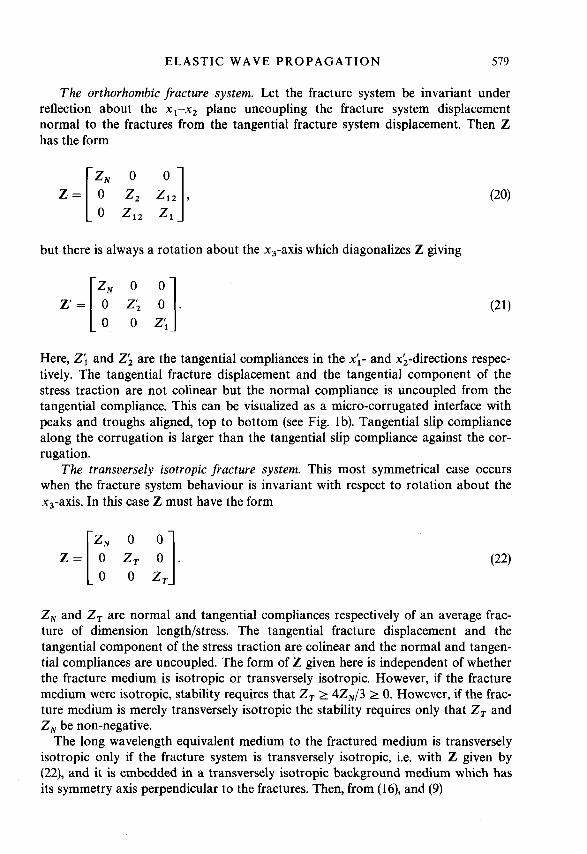
The orthorhombic fracture system. Let the fracture system be invariant under reflection about the x1-x2 plane uncoupling the fracture system displacement normal to the fractures from the tangential fracture system displacement. Then Z has the form
Z =
but there is always a rotation about the x,-axis which diagonalizes Z giving
-zN 0 z; O q. 0 0 z;
Here, Z; and 2; are the tangential compliances in the xi- and xi-directions respec- tively. The tangential fracture displacement and the tangential component of the stress traction are not colinear but the normal compliance is uncoupled from the tangential compliance. This can be visualized as a micro-corrugated interface with peaks and troughs aligned, top to bottom (see Fig. lb). Tangential slip compliance along the corrugation is larger than the tangential slip compliance against the cor- rugation.
The transversely isotropic fracture system. This most symmetrical case occurs when the fracture system behaviour is invariant with respect to rotation about the x,-axis. In this case Z must have the form
Z , and Z , are normal and tangential compliances respectively of an average frac- ture of dimension length/stress. The tangential fracture displacement and the tangential component of the stress traction are colinear and the normal and tangen- tial compliances are uncoupled. The form of Z given here is independent of whether the fracture medium is isotropic or transversely isotropic. However, if the fracture medium were isotropic, stability requires that Z , 2 4zN/3 2 0. However, if the frac- ture medium is merely transversely isotropic the stability requires only that Z , and Z , be non-negative.
The long wavelength equivalent medium to the fractured medium is transversely isotropic only if the fracture system is transversely isotropic, i.e. with Z given by (22), and it is embedded in a transversely isotropic background medium which has its symmetry axis perpendicular to the fractures. Then, from (16), and (9)

580 M . SCHOENBERG A N D J . D O U M A
(23)
c11 0
where
E , E c ~ ~ ~ Z N , ET E ~ 4 4 ~ 2 T .
E , and ET are dimensionless compliances that give the fracture system compliances relative to the background medium compliances, normal and tangential to the frac- ture system respectively. The modulus matrix depends on seven parameters, the five of the background plus the normal and tangential fracture system compliances. When the background medium is isotropic, the resulting medium is still transversely isotropic, but now depends on four parameters, pb , & , E, and ET. The moduli are
matrices of the changes from the isotropic moduli due to the presence of the frac- given by (23) with C l l b = C3sb = 1, + 2&, C 1 3 b = & and C44b = C6(jb = pb. The
tures are
AN= -
This is the very simple model for the behaviour of large joints in an isotropic back- ground. These results agree with those of Morland (1974) and have been used to describe reflectivity from a jointed half-space by Schoenberg (1983).
ELASTIC WAVE P R O P A G A T I O N 58 1
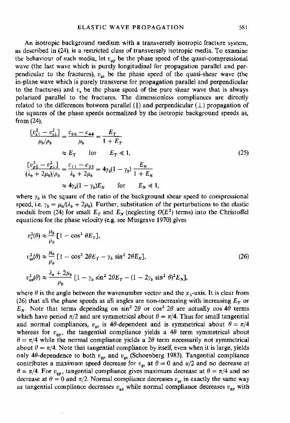
An isotropic background medium with a transversely isotropic fracture system, as described in (24), is a restricted class of transversely isotropic media. To examine the behaviour of such media, let uqp be the phase speed of the quasi-compressional wave (the fast wave which is purely longitudinal for propagation parallel and per- pendicular to the fractures), uqs be the phase speed of the quasi-shear wave (the in-plane wave which is purely transverse for propagation parallel and perpendicular to the fractures) and U , be the phase speed of the pure shear wave that is always polarized parallel to the fractures. The dimensionless compliances are directly related to the differences between parallel ( 1 1 ) and perpendicular (I) propagation of the squares of the phase speeds normalized by the isotropic background speeds as, from (24),
Cuz11 - u,?ll - c66 - c44 E T
pb/Pb pb 1 + ET - -
W 4 ~ b ( l - yb)EN for E , 4 1, where Y b is the square of the ratio of the background shear speed to compressional speed, i.e. Y b = pb/(& + 2&). Further, substitution of the perturbations to the elastic moduli from (24) for small ET and E , (neglecting O(E’) terms) into the Christoffel equations for the phase velocity (e.g. see Musgrave 1970) gives
U : ( 8 ) % lb [1 - cos’ BE,], P b
where 8 is the angle between the wavenumber vector and the x3-axis. It is clear from (26) that all the phase speeds at all angles are non-increasing with increasing ET or E, . Note that terms depending on sin’ 28 or cos’ 2 8 are actually cos 48 terms which have period 7c/2 and are symmetrical about 8 = 44. Thus for small tangential and normal compliances, uqs is 48-dependent and is symmetrical about 8 = n/4 whereas for uqp, the tangential compliance yields a 48 term symmetrical about 8 = 744 while the normal compliance yields a 28 term necessarily not symmetrical about 8 = n/4. Note that tangential compliance by itself, even when it is large, yields only 48-dependence to both uqp and ugs (Schoenberg 1983). Tangential compliance contributes a maximum speed decrease for uqs at 8 = 0 and 742 and no decrease at 8 = n/4. For u q p , tangential compliance gives maximum decrease at 8 = 7114 and no decrease at 8 = 0 and 4 2 . Normal compliance decreases uqs in exactly the same way as tangential compliance decreases uqp while normal compliance decreases uqp with

582 M . S C H O E N B E R G A N D J . D O U M A
maximum decrease at 8 = 0 and minimum decrease at 0 = 4 2 . The pure shear wave is uncoupled (in the Christoffel equations) from the other two waves. Its greatest speed decrease is at 8 = 0 and there is no decrease at 8 = 4 2 .
This is a simplified picture due to the assumptions of (1) small fracture compli- ance relative to the compliance of the unfractured medium, ( 2 ) isotropy for the unfractured medium, and (3) transverse isotropy for the behaviour of the fracture system. None the less, (26) indicates the qualitative effects of the presence of large aligned fractures (and, as will be seen below, also of the presence of aligned microcracks) on wave speeds in much more general circumstances.
Equations (24), and the resulting ( 2 6 ) , can be compared with the formulation of Thomsen (1986). His three dimensionless anisotropy parameters for weak transverse isotropy, Y T h , &Th and 6 T h (the subscript Th refers to Thomsen’s parameters) along with the shear and compressional wave speed along the symmetry axis of the medium are derivable from the elastic moduli. The three dimensionless parameters express, in general, the deviation of the weakly transverse isotropy from full iso- tropy. For a fractured medium, the three parameters can be expressed in terms of E T and ENas
Thus, the three are not independent for a fractured medium and, until the assumption of microcrack flatness is relaxed, the anisotropy depends only on two parameters, E T and E,.
111. JOINTS A N D MICROCRACKS The anisotropy described by the changes of the moduli from an isotropic back- ground, (24), defines a restricted class of transversely isotropic media. Hudson (1981) pointed out that “although the geometry ofjoints is rather different from that of circular cracks . . . under certain conditions, the results are very similar.” To see this, we shall examine results from Hudson (1981) and Thomsen (1988) to show that under simple conditions of dilute concentration of very flat microcracks (those where one of the ellipsoidal semiaxes is much less than the other two) in an isotropic background, we can always find joint compliances that give identical values for all the anisotropic elastic moduli. This implies that a seismic experiment giving esti- mates of the moduli for a Crampin model (azimuthal anisotropy due to the presence of a vertical system of aligned microcracks in an isotropic background which cause the medium to be transversely isotropic with a horizontal axis of symmetry) does not distinguish very well between various types of crack systems. Refinements in the theory of scattering due to flat microcracks will not help in inverting for the crack system’s characteristic properties, such as crack size, crack density or the contents of the cracks. Only properties that systems of cracks have in common with those of systems of large vertical joints (such as orientation, excess compliance, relative tangential to normal compliance) have a chance of being determined, but in many instances these could be very informative.

ELASTIC WAVE PROPAGATION 583
Hudson (1981) gives the general form of the 6 x 6 change of moduli matrix for an isotropic background medium permeated with aligned flat ellipsoidal microcracks to lowest order in wavenumber times mean crack radius U. For ease of comparison we can express Hudson's matrix (denoted by subscript H) using our formulation of three 3 x 3 matrices, giving
where e is the crack density which is equal to the crack number density (number of cracks per unit volume) times u3. Note that crack porosity, which is crack number density times the mean crack volume is given by $c = 47cea/3 where CI is the (very small) mean aspect ratio of the flat ellipsoidal inclusions. The terms U , , and U 3 , appearing in (28) arise in the derivation of the scattered field from a single small crack. Essentially Uij is the integral over the face of the crack of the ith component of the displacement discontinuity due to unit stress Q~~ imposed infinitely far from the crack in the f x3-directions.
Comparing (24) and (28) shows that both flat microcracks and large joints in the same isotropic background give exactly the same moduli if, assuming a dilute con- centration of inclusions, we let
eUl l =- E T % E T for E , Q 1, e - = - % E , for E , Q 1. 1 + E T Yb ' + E h '
Thomsen (1988) points out that the derivations for dilute concentrations of flat aligned microcracks are valid for e only as large as about 0.05. However, even if second-order terms in e are included (Crampin 1984), the slip-joint model still con- forms to the microcrack model except that there are additional terms proportional to e2 on the left-hand sides of (29).
Hudson (1981) gives results for U I 1 and if,, for three examples which we will write in terms of E , and E, . Example 1 is for fluid-filled cracks under the assump- tions that (a) the tangential component of the traction on the internal crack surfaces is zero (no shear stress) and (b) the crack is so thin that the normal displacement discontinuity across the crack is zero (only tangential displacement discontinuity
584 M . SCHOENBERG A N D J . D O U M A
across the crack). Then
e , E , = 0. 1 6
ET = 3[3 - 2Ybl
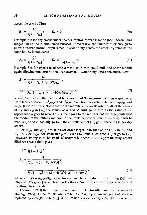
Example 2 is for dry cracks under the assumption of zero traction (both normal and tangential) on the internal crack surfaces. These cracks are assumed thick enough to allow non-zero normal displacement discontinuity across the crack. ET remains the same but E , is non-zero :
Example 3 is for cracks filled with a weak solid with small bulk and shear moduli again allowing non-zero normal displacement discontinuity across the crack. Now
where p‘ and K‘ are the shear and bulk moduli of the inclusion medium respectively. Here terms of order a, t12p,,/,d and a2&/K‘ have been neglected relative to tl&/p’ and tl&,/d (Hudson 1 9 8 1 ) . Note that for the moduli of the weak solid to affect the values of ET and E , in (32), the values of p’ and K’ must go to zero as the value of the aspect ratio a goes to zero. This is analogous to the requirement for large joints that the moduli of the infilling material in the joints be proportional to h, as h, tends to zero. As p’ and K‘ actually go to 0, the compliances of ( 3 2 ) go to those of ( 3 1 ) for dry cracks.
For d / p b and PI/&, not small (of order larger than that of CI as a --t 0), E , and E T - + O . For d/&, not small but $ / f i b - + O as for fluid-filled cracks, ( 3 2 ) go to (30). However, letting d/&, be small, of order a but with p’ = 0, approximating cracks filled with weak fluid, gives
where K b = (3 - 4Yb)pL,/3Yb is the background bulk modulus. Substituting (33 ) into ( 2 6 ) and (27) gives ( 3 ) of Thomsen ( 1 9 8 8 ) for his three anisotropy parameters and resulting phase speeds.
Thomsen ( 1 9 8 8 ) then presented modified results [his ( 4 ) ] based on the work of Hoenig ( 1 9 7 9 ) . These results are similar to (33 ) ; ET is unchanged but d / K b is replaced by (K’ /k&) / [ l - ( d / K b ) ] in E , . When K ‘ / K b u is 0 ( 1 ) , d / K b < 1 , there is no
ELASTIC WAVE PROPAGATION 585
difference between the two sets of results. In the stiff fluid limit, when d / K b (and hence J C ' / ~ ~ also) is O(1), E, is O(a) and hence tends to zero in both (32) and (33). Thus there is no significant difference between the two sets of results.
Further results are derived by Thomsen (1988) for when the background uncracked medium has equant (non-directional) porosity 4 p , i.e. porosity in which the pore space has no dimension significantly larger or smaller than any other and so the pore space can be modelled by spherical pores. His results, again in terms of the dimensionless compliances, ET and E,, are that E, is unchanged due to the presence of equant porosity but E,, from [derived by substituting (A34b) into (A16a) Thomsen (1988)l becomes
K' 1 -
(34) 4 Kb(1 + 4,/43
Ie. E, = - 4Yb
+ - ICfhb ICf/Icb " 4Yb + 3nayb(1 - Yb) + 4 p / 4 c
3Yb(1 - Yb)
As 4,,+0, E, of (34) goes to Thomsen's (1988) modified result for E , with no equant porosity, that is, (33) with K'/Kb replaced by (K'/Kb)/[l - (d/Kb)]. This may be seen as even when +,,/4, is 0(1) or less, the second term within the brackets of the denominator of (34) dominates the first term due to the presence of the small U, the aspect ratio, in the denominator of that second term. When cjP/4, is large (which it is in typical sedimentary rocks), so that multiplication by a gives a term of order unity, the two bracketed terms are of the same order of magnitude. Then in the weak fluid limit, d / K b < 1, the right-hand fraction of (34) tends to unity and E, tends to the value given for it in (31). For a stiff fluid when d/q, --+ 1, the presence of the 1 - d / K b term implies that E , becomes small.
IV. NON-FLAT ELLIPSOIDAL INCLUSIONS For all the models discussed so far, an underlying assumption has been that the cracks are flat, i.e. that they can be modelled by ellipsoids with aspect ratio a 4 1. These models have all been shown to be identical in behaviour with the medium with large joints (itself an extreme case of aspect ratio --+ 0). Nishizawa (1982) calcu- lated the anisotropy due to small concentrations of aligned rotationally-symmetrical ellipsoidal inclusions of any aspect ratio, even including prolate spheroidal inclu- sions which have an aspect ratio greater than unity. As this is an iterative method using only small increments in crack density at each step, Nishizawa claimed that the method is valid even for large concentrations of inclusions.
Following Nishizawa (1982), the effects of a given crack density e of ellipsoids are calculated in an iterative way. First the moduli for an isotropic background medium with a crack density of e/n is calculated, with n the total number of iterations. Then the moduli for this new ' anisotropic background medium' with

586 M . SCHOENBERG AND J . DOUMA
additional crack density e/n is calculated giving the moduli for the original medium with crack density 2e/n. This is repeated another n - 2 times eventually giving the moduli for the original medium with crack density e, the desired result. Results can be checked by repeating the calculation with larger values of n until no change due to increasing n occurs. The resulting medium is transversely isotropic and we denote the changes in the elastic moduli due to Nishizawa’s procedure by AcC cz - cijb . To see how well these moduli, and thus the Nishizawa model, can be approximated by the model of large joints in an isotropic background, we construct D2, defined to be one-fifth of the sum of the squares of the differences between the dimensionless moduli changes (over the five independent elastic moduli) from the Nishizawa pro- cedure, AcC/cijb, i j = 11, 33, 13, 44, 66 and the dimensionless moduli changes from the joint model, Ac$/cijb, ij = 11, 33, 13, 44, 66, from (24). The root mean square of the differences of the five elastic moduli D satisfies
The values of E, and E, that minimize D2, in terms of the Nishizawa moduli CC = cijb + AcC , are given by
These values of E, and E, give the elastic moduli of the joint model that best fit those of the Nishizawa’s ellipsoids model in a least-squares sense. Also note that these values of E, and EN are independent of c“, so that the last term of (35) gives a minimum value to D2 below which no combination of E, and E , can cause the value of D2 to fall. However, as the aspect ratio a + 0 for any small value of e, Ac& and D approach zero. This becomes clear when we calculate the c; over a wide range of aspect ratio (from 10-3 to 1) for gas-filled ellipsoidal inclusions. In a homo- geneous isotropic background, with yb = 113 (Poisson’s ratio = 1/4), the gas is assumed to have a vanishing shear modulus and a bulk modulus equal to 0.0128 x pb. For this model, Fig. 2 shows D as a function of a while e is held constant at
three values, 0.001 0.01 and 0.05. D is very small for small values of a and only exceeds 0.05 (which we consider the point where meaningful difference between the joint model and the ellipsoid model begins) for e = 0.05 when a > 0.316 for which crack porosity 6, > 0.066. The same calculations have been carried out for empty

ELASTIC WAVE P R O P A G A T I O N 587
Log (X
FIG. 2. The root mean square difference D (in %) between the five elastic moduli computed according to Nishizawa (1982) and those five moduli computed from values of E , and E , which minimize D as functions of aspect ratio GI holding e (the crack number density x the mean crack radius cubed) constant. The curve (-) is for e = 0.001, (----) for e = 0.01 and (-.-.-.- ) for e = 0.05. The background medium has a Poisson’s ratio of 1/4 and the ellipsoids are filled with gas assumed to have vanishing shear modulus and a bulk modulus equal to 0.0128-the shear modulus of the background medium.
(dry) inclusions and for liquid-filled inclusions (vanishing shear modulus and bulk modulus equal to 0.0385 x pb) giving almost the same results for D. The values of D become smaller with the shrinking of the acoustic contrast between the background medium and the material filling the inclusions. The high contrast between the back- ground and the inclusion medium shown here may be thought of as a worst case for matching with the jointed model.
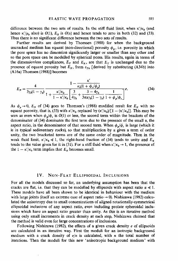
Figure 3 shows D as a function of a for the same gas-filled inclusions while crack porosity 4 (equal to 47me/3) is held constant for four values of porosity, 4 = 0.01, 0.03, 0.05 and 0.07. To avoid values of e larger than 0.05, an approximate upper limit for single scattering theory, each curve starts at the aspect ratio corresponding to e = 0.05, i.e. at astart = 34/(4x x 0.05). Each curve continues to larger aspect ratios for which the values of e necessary to maintain constant porosity shrink accordingly. D increases with increasing aspect ratio whether crack density is held constant or whether porosity is held constant. For these gas-filled inclusions, a porosity of at least 0.05 is required for D to exceed 5% and that occurs for 4 = 0.05 at aspect ratio a = 0.44 (see Fig. 3).
588 M . SCHOENBERG AND J . DOUMA
/
0 .05 , ' .--
0 1 1 -2 - 1 0
Log a
FIG. 3. As for Fig. 2 except here D is shown as a function of aspect ratio GI holding crack porosity 4 constant. The curve (-) is for 4 = 0.01, (--------) for 4 = 0.03, (----) for 4 = 0.05 and (-.-.-.- ) for 4 = 0.07.
DISCUSSION A N D CONCLUSIONS
The behaviour of parallel linear-slip interfaces has been used to model the long wavelength propagation characteristics of a medium with a set of large parallel joints or fractures much larger than the largest wavelength but spaced much closer than the smallest wavelength. This model gives geometrical insight into the mecha- nical properties of such a fractured medium by letting us visualize the action of the planes of weakness in a solid. In addition, we have shown that the linear-slip inter- face model exactly describes the behaviour of systems of aligned flat microcracks according to Hudson (1981). However, as the aspect ratio of the microcracks grows, i.e. the microcracks become less flat, the results of Nishizawa's (1982) iterative method to compute moduli for a solid with aligned ellipsoidal inclusions deviate increasingly from the linear-slip interface model. But this linear-slip interface model is a good approximation even for aspect ratios as large as 0.3 when e = 0.05 (which is about as large a value of e as one can assume and still hope that single scattering theory is valid).
All possible types of fracture system anisotropy : triclinic, monoclinic, orthorhom- bic or transversely isotropic, and all anisotropic elastic backgrounds are included in the model. To compute the elastic moduli of the equivalent medium, once the frac- ture system compliance matrix is given, requires at most the inversion of two 3 x 3 matrices.

ELASTIC WAVE P R O P A G A T I O N 589
Azimuthal anisotropy has been assumed to be caused by aligned sets of vertical fractures and microcracks. It has been shown that large joints are indistinguishable from dilute systems of flat microcracks. Assuming rotationally isotropic fractures (which is suspect, but perhaps a good first approximation) means that azimuthal anisotropy may be characterized by three scalar quantities, the orientation of the normal to the system and the two compliances, 2, and 2,. A good approximation to a vertically cracked earth, for which conventional transverse isotropy is often an order of magnitude larger than the azimuthal anisotropy, might be a transversely isotropic (with vertical axis) background with a rotationally isotropic vertical frac- ture system. Such a model allows for the additional compliance due to the presence of fractures or cracks in a physically meaningful way even when the underlying fracture mechanism is not fully understood. The values of 2, and 2, , dimensionless with respect to the appropriate background modulus, quantify in the simplest way the azimuthal anisotropy. In many situations it has been shown that the normal compliance can be very small. Assuming that 2, vanishes leaves only one parameter quantifying azimuthal anisotropy but this is a key parameter as it still allows for shear-wave splitting for shear waves propagating parallel to the fractures.
ACKNOWLEDGEMENT We thank Schlumberger-Doll Research for their hospitality to one of the authors (J.D.) during the autumn of 1986.
REFERENCES BACKUS, G.E. 1962. Long-wave anisotropy produced by horizontal layering. Journal of Geo-
physical Research 66,44274440. CRAMPIN, S . 1984. Effective anisotropic elastic constants for wave propagation through
cracked solids. Geophysical Journal of the Royal Astronomical Society 76, 135-145. CRAMPIN, S. 1985. Evidence for aligned cracks in the Earth’s crust. First Break 3, (3), 12-15. CRAMPIN, S. and ATKINSON, B.K. 1985. Microcracks in the Earth’s crust. First Break 3, (3),
CRAMPIN, S. and BUSH, I. 1986. Shear waves revealed, extensive-dilatancy anisotropy con-
HELBIG, K. and SCHOENBERG, M. 1987. Anomalous polarization of elastic waves in trans-
HOENIG, A. 1979. Elastic moduli of a non-randomly cracked body. International Journal of
HUDSON, J.A. 1981. Wave speeds and attenuation of elastic waves in material containing
MORLAND, L.W. 1974. Elastic response of regularly jointed media. Geophysical Journal of the
MUSGRAVE, M.J.P. 1970. Crystal Acoustics, 84-86. Holden-Day, Inc. NISHIZAWA, 0. 1982. Seismic velocity in a medium containing oriented cracks-transversely
16-20.
firmed. 56th S.E.G. meeting, Houston, Expanded Abstracts, 481484.
versely isotropic media. Journal of the Acoustical Society of America 81, 1235-1245.
Solids and Structures 15, 137-154.
cracks. Geophysical Journal of the Royal Astronomical Society 64, 133-150.
Royal Astronomical Society 37,435446.
isotropic case. Journal of the Physics of the Earth 30, 331-347.

590 M. SCHOENBERG AND J. DOUMA
SCHOENBERG, M. 1980. Elastic wave behavior across linear slip interfaces. Journal of the
SCHOENBERG, M. 1983. Reflection of elastic waves from periodically stratified media with
SCHOENBERG, M. and MUIR, F. 1988. Group theoretic methods for finely layered media. Geo-
THOMSEN, L. 1986. Weak elastic anisotropy. Geophysics 51, 1954-1966. THOMSEN, L. 1988. Elastic anisotropy due to aligned cracks. Geophysical Journal of the Royal
Astronomical Society (submitted). WILLIS, H.A., RETHFORD, G.L. and BIELANSKI, E. 1986. Azimuthal anisotropy, occurrence and
effect on shear-wave data quality. 56th S.E.G. meeting, Houston, Expanded Abstracts, 479481.
Acoustical Society of America 68, 15161521.
interfacial slip. Geophysical Prospecting 31, 265-292.
physics (submitted).